Embed Size (px)
Citation preview
1
River Valley High School Page 1 of 16 Year 6 H2 Physics 9749Preliminary Examinations 2018
RIVER VALLEY HIGH SCHOOLYEAR 6 PRELIMINARY EXAMINATIONS
H2 PHYSICS 9749 / 1 PAPER 1
19 SEPTEMBER 2018
1 HOUR
CANDIDATE NAME
CENTRE NUMBER
S INDEX NUMBER
CLASS 6
INSTRUCTIONS TO CANDIDATES
DO NOT OPEN THIS BOOKLET UNTIL YOU ARE TOLD TO DO SO.
Read these notes carefully. Write your name, centre number, index number and class above. There are thirty questions in this paper. Answer all questions. For each question, there are four possible answers, A, B, C and D. Choose the one you consider correct and record your choice in soft pencil on the separate Answer Sheet. Read the instructions on the Answer Sheet very carefully. Each correct answer will score one mark. A mark will not be deducted for a wrong answer. Any rough working should be done on the Question Paper. The use of an approved scientific calculator is expected where appropriate. The total number of marks for this paper is 30. ____________________________________________________________________________
This Question Paper consists of 15 printed pages and 1 blank page.
2
River Valley High School Page 2 of 16 Year 6 H2 Physics 9749Preliminary Examinations 2018
Data speed of light in free space, c = 3.00 × 10⁸ m s–1
permeability of free space, μ0 = 4π × 10–7 H m–1
permittivity of free space, ε0 = 8.85 × 10⁻¹² F m–1
= (1/(36π )) × 10–9 F m–1
elementary charge, e = 1.60 × 10⁻¹⁹ C
the Planck constant, h = 6.63 × 10⁻³⁴ J s
unified atomic mass constant, u = 1.66 × 10⁻²⁷ kg
rest mass of electron, me = 9.11 × 10⁻³¹ kg
rest mass of proton, mp = 1.67 × 10⁻²⁷ kg
molar gas constant, R = 8.31 J K–1 mol–1
the Avogadro constant, NA = 6.02 × 10²³ mol–1
the Boltzmann constant, k = 1.38 × 10⁻²³ J K–1
gravitational constant, G = 6.67 × 10⁻¹¹ N m2 kg–2
acceleration of free fall, g = 9.81 m s–2

3
River Valley High School Page 3 of 16 Year 6 H2 Physics 9749Preliminary Examinations 2018
Formulae
uniformly accelerated motion 221 atuts +=
2 2 2v u as= +
work done on / by a gas W p V= Δ
hydrostatic pressure p ghρ=
gravitational potential φ = − GM / r temperature T / K = T / °C + 273.15
pressure of an ideal gas ><= 2
31
cV
Nmp
mean translational kinetic energy of an ideal gas molecule kTE23=
displacement of particle in s.h.m., x = x0 sin ωt velocity of particle in s.h.m., v = v0 cos ωt = )( 22
0 xx −± ω electric current, I = Anvq resistors in series, 1 2R R R= + + K resistors in parallel, 1 21/ 1/ 1/R R R= + + K
electric potential, r
QV
04πε=
alternating current/voltage, x = x0 sin ωt
magnetic flux density due to a long straight wire, d
Bπ
μ2
0I=
magnetic flux density due to a flat circular coil, r
NB
20 Iμ=
magnetic flux density due to a long solenoid, InB 0μ=
radioactive decay, x = x0 exp (−λt)
decay constant,
2
1
2lnt
=λ

4
River Valley High School Page 4 of 16 Year 6 H2 Physics 9749Preliminary Examinations 2018
For each question there are four possible answers, A, B, C and D. Choose the one you consider to be correct.
1 The speed v of a liquid leaving a tube depends on the change in pressure ΔP and the density ρ of the liquid. The speed is given by the equation
n
ρ
Pkv
Δ=
where k is a constant that has no units. What is the value of n?
A
2
1 B 1 C
2
3 D 2
2 Ball A is launched up the slope from the bottom of a smooth inclined plane with an initial
speed v. At the same time that ball A is launched, ball B is released from rest at the top of the inclined plane. The two balls meet at the mid-point of the inclined plane after two seconds.
Given that the mass of ball A is twice that of ball B, what is the speed v?
A 4.9 m s–1
B 9.8 m s–1
C 17 m s–1
D 20 m s–1
3 A ball is thrown vertically upwards. It reaches its maximum height of motion and comes
back to the original point where it was launched.
Given that air resistance to the motion of the ball is not negligible, which of the following statements about the ball is correct?
A The ball is accelerating at − 9.81 m s−2 throughout its motion.
B The ball is decelerating at a decreasing rate when it is moving upwards.
C The ball is decelerating at an increasing rate when it is moving upwards.
D The ball is accelerating at an increasing rate when it is moving downwards.
ball A
ball B
30o
v

5
River Valley High School Page 5 of 16 Year 6 H2 Physics 9749Preliminary Examinations 2018
4 A ball of weight W moves along a smooth horizontal surface until it falls off the edge at time T.
Given that air resistance is not negligible, which of the following graphs shows the variation with time t of the resultant vertical force F acting on the ball as it moves from P to Q?
A
B
C
D
P
Q
T 0 t
F
− W
T 0 t
F
W
T 0 t
F
W
T 0 t
F
− W

6
River Valley High School Page 6 of 16 Year 6 H2 Physics 9749Preliminary Examinations 2018
5 A man’s 2.0 m long fishing pole makes an angle of 30° with the horizontal. What is the moment exerted by the fish about the man’s hand at P?
A 75 N m
B 77 N m
C 110 N m
D 290 N m
6 A 3.50 g balloon is filled with helium (density = 0.180 kg m–3) to a volume of 5.00 m3 and is
then connected to the top of a table via a light spring of constant k = 100 N m–1. The balloon causes the spring to stretch. What is the extension of the spring when the balloon is in equilibrium given that the density of air is 1.29 kg m–3?
A 0.055 m
B 0.201 m
C 0.544 m
D 0.632 m
30° 45°
150 N
2.0 m
P

7
River Valley High School Page 7 of 16 Year 6 H2 Physics 9749Preliminary Examinations 2018
7 A mini rocket of mass 90 kg requires 28 kW of useful power in order to travel horizontally at a constant speed. The driving force on the rocket is given as 760 N. What is the useful power required by the rocket to travel vertically at the same constant speed?
A 28 kW
B 33 kW
C 61 kW
D 68 kW
8 The closed cylinder shown in the figure below has a freely moving piston separating
chambers 1 and 2. Chamber 1 contains 20 mg of nitrogen gas and chamber 2 contains 45 mg of helium gas. The relative molecular mass of nitrogen is 28 and that of helium is 4. When both pressure and thermal equilibrium are established between chamber 1 and 2, what is the ratio of L1 / L2?
A 0.063 B 0.44 C 2.3 D 16
9 A fixed mass of an ideal gas undergoes the changes represented by XYZX below.
Which one of the following sets could describe this set of changes?
XY YZ ZX
A isothermal expansion
adiabatic compression
pressure reduction at constant volume
B
adiabatic expansion
isothermal compression
compression at constant pressure
C
isothermal expansion
adiabatic compression
compression at constant pressure
D
adiabatic expansion
isothermal compression
pressure reduction at constant volume
volume
pressure
chamber 1 chamber 2
L1 L2
X Z
Y

8
River Valley High School Page 8 of 16 Year 6 H2 Physics 9749Preliminary Examinations 2018
10 A drone is performing a stunt for its audience on the ground by flying in a vertical circle. Which diagram shows the resultant acceleration a acting on the drone at the instant where its velocity is v and is speeding up?
A
B
C
D
11 A spacecraft orbiting a planet in uniform circular motion has an antenna detached gently
from it. Neglecting air resistance, which statement best describes the motion of this detached antenna?
A It will move off in a straight line away from the planet.
B It will take a parabolic path into the planet.
C It will continue to orbit in uniform circular motion.
D It will drop straight down into the planet.
12 A satellite of mass 80 kg moves from a point where its gravitational potential energy due
to Earth is −4800 MJ, to another point where its gravitational potential energy is −1600 MJ. In which direction does the satellite move and what is the change in gravitational potential between these two points?
A closer to the Earth and a decrease of 40 MJ kg−1 of potential
B closer to the Earth and a decrease of 3200 MJ kg−1 of potential
C further from the Earth and an increase of 40 MJ kg−1 of potential
D further from the Earth and an increase of 3200 MJ kg−1 of potential
V
a
V
a
V a
V
a

9
River Valley High School Page 9 of 16 Year 6 H2 Physics 9749Preliminary Examinations 2018
13 A particle executes simple harmonic motion about a point. Its maximum speed is 6.0 m s–1 and its maximum acceleration is 2.0 m s–2. What is the amplitude of its motion and its period?
amplitude / m period / s A 0.33 0.35
B 0.33 18
C 18 0.33
D 18 19
14 An oscillating system has a natural period of 1.0 s. A periodic force of 2.0 Hz is then applied
to the system, reaching a steady state. What is the time interval between successive instances where the magnitude of the displacement is at a maximum?
A 0.25 s
B 0.50 s
C 0.75 s
D 1.0 s
15 Diagram 1 shows a ripple tank experiment in which plane waves are diffracted through a
narrow slit in a metal sheet. Diagram 2 shows the same tank with a slit of greater width. In each case, the pattern of the waves incident on the slit and the emergent pattern are shown.
Which action would cause the waves in diagram 2 to be diffracted more and so produce an emergent pattern closer to that shown in diagram 1?
A decreasing the density of the liquid
B decreasing the frequency of vibration of the bar
C decreasing the speed of the waves by making the water in the tank shallower
D increasing the amplitude of vibration of the bar

10
River Valley High School Page 10 of 16 Year 6 H2 Physics 9749Preliminary Examinations 2018
16 A standing sound wave is set up between a loudspeaker and a wall. A microphone is connected to a cathode-ray oscilloscope (c.r.o.) and is moved along a line directly between the loudspeaker and the wall. The amplitude of the trace on the c.r.o. rises to a maximum when the microphone is at a position X, falls to a minimum and then rises once again to a maximum at a position Y. The distance between X and Y is 33.4 cm. The speed of sound in air is 334 m s–1. Which diagram represents the c.r.o. trace of the sound received by the microphone at X?
A B
C D
17 There is a current flowing from P to R in
the resistor network shown. The potential difference (p.d.) between P and Q is 3 V. The p.d. between Q and R is 6 V. The p.d. between P and S is 5 V. Which row in the table is correct?
p.d. between Q and S p.d. between S and R
A 2 V 4 V
B 2 V 10 V
C 3 V 4 V
D 3 V 10 V

11
River Valley High School Page 11 of 16 Year 6 H2 Physics 9749Preliminary Examinations 2018
18 A uniform copper rod of cross-sectional area 8.0 × 10⁻⁶ m2 has 8.5 × 1028 conduction
electrons per cubic metre. A current flows through the rod when a potential difference is applied across it. Given that the drift velocity of electrons in the rod is 2.3 × 10⁻⁵ m s−1, what is the current in the rod?
A 0.25 A
B 0.40 A
C 2.5 A
D 4.0 A
19 An oil drop of charge q and mass m is suspended at the midpoint of parallel charged plates
X and Y. The drop is at a distance d from plate Y. Plate X is earthed while Y is held at a potential of V with a total charge of QY.
What is the expression for the potential V?
A mgd
q
B 2mgd
q
C mg
q
D 04
YQ
dπε
d
V
X
Y
q

12
River Valley High School Page 12 of 16 Year 6 H2 Physics 9749Preliminary Examinations 2018
20 The simplified interaction between a pair of atoms can be represented by an equation
relating the electric potential energy of the atoms,
12 6
A BU
r r= −
where U is the electric potential energy of the atoms, r is the separation between them and A and B are constants. The variation of U with r is as shown below.
Which of the following statements is correct?
A The atoms experience no interatomic forces at the separation of r0.
B The atoms experience the strongest forces of attraction as r decreases from r0.
C To separate the atoms, the atoms must decrease electric potential energy by a magnitude of U0.
D As the separation between the atoms increases from r0, the magnitude of net force acting on the atoms increases then decreases.
21 The diagram shows a network of 7 resistors, each with resistance R.
What is the resistance between points X and Y?
A
2
3R B
3
5R C
7
11R D
11
15R
U0
U
rr0

13
River Valley High School Page 13 of 16 Year 6 H2 Physics 9749Preliminary Examinations 2018
22 Two cells of e.m.f. E1 and E2 have internal resistances R and zero respectively. The cells are connected to resistors of resistances 3R, 2R and R, as shown below.
If the galvanometer shows no deflection, what is the ratio 2
1
E
E?
A 0.60 B 1.0 C 1.7 D 2.0
23 Two parallel wires P and Q are placed a distance x from each other. P carries a current of
I vertically down into the paper while Q carries twice the current of P vertically out of the paper.
A third current-carrying wire R is placed along the dotted line, parallel to wires P and Q, and experiences no net force from wires P and Q. Which of the following is a possible combination of the position of wire R, and the direction and magnitude of current in R?
position of R direction of current in R magnitude of current in R
A x to the left of P out of paper 2 I
B 0.5x to the left of P into paper I
C 2x to the left of P out of paper I
D x to the right of Q out of paper I
QP
x
×
E1
3R 2R
E2
R
R
R

14
River Valley High School Page 14 of 16 Year 6 H2 Physics 9749Preliminary Examinations 2018
24 The diagram shows a long horizontal wire carrying a steady current. A source fires a beam of electrons towards the wire at an angle of 45°.
As the beam approaches the wire, the electrons experience an electromagnetic force from the field of the current. What is the initial direction of this force?
A in a direction parallel to the wire
B in a vertical direction towards the wire
C in a direction at 90° to the original path towards the wire
D in a direction at 90° to the original path away from the wire
25 An aluminium disc of diameter d rotates about its centre. A point on the rim moves at a
constant speed v. It is placed in a uniform magnetic field B perpendicular to its surface. A steady electromotive force (e.m.f.) E is generated between the centre O and the rim at P.
What is the expression for the e.m.f E generated?
A Bdv
4
B Bdv
2
C Bdv
D Bv
26 A half-wave rectified sinusoidal alternating current has r.m.s. current of I.
Which expression is correct for the peak current I0?
A I√2
B I2
C √2 I D 2 I
current
source
P
O d
v

15
River Valley High School Page 15 of 16 Year 6 H2 Physics 9749Preliminary Examinations 2018
27 The velocity of a proton is twice the velocity of an electron. Assuming the mass of a proton is approximately 2000 times larger than the mass of an electron, what is the ratio of the de Broglie wavelength of the proton to that of the electron?
A 2.5 ×10⁴ B 0.50 C 2.0 D 4000
28 A metal plate with work function energy of 2.6 eV, is illuminated with electromagnetic
radiation of wavelength 80 nm. What is the maximum velocity of emitted photoelectrons?
A 1.5 × 10⁶ m s–1
B 2.1 × 10⁶ m s–1
C 2.5 × 10⁶ m s–1
D 6.7 × 10⁷ m s–1
29 Nuclear decay is both spontaneous and random in nature.
Which row gives the correct experimental evidence for these properties?
spontaneous nature of decay random nature of decay
A the decay rate is not affected by pressure
the decay rate is not affected by temperature
B the decay rate is not affected by temperature
the rate at which radiation is received at a counter fluctuates
C the rate at which radiation is received at a counter fluctuates
the decay rate is not affected by temperature
D the decay rate is not affected by temperature
the decay rate is not affected by pressure
30 Uranium decays to form lead by a series of alpha and beta emissions.
For each decay of uranium to lead , how many α−particles and β−particles are
emitted? α−particles β−particles A 6 2
B 6 8
C 8 4
D 8 6
END OF PAPER

16
River Valley High School Page 16 of 16 Year 6 H2 Physics 9749Preliminary Examinations 2018
BLANK PAGE
River Valley High School Pg 1 of 6 Year 6 H2 Physics 9749Preliminary Examination I 2018
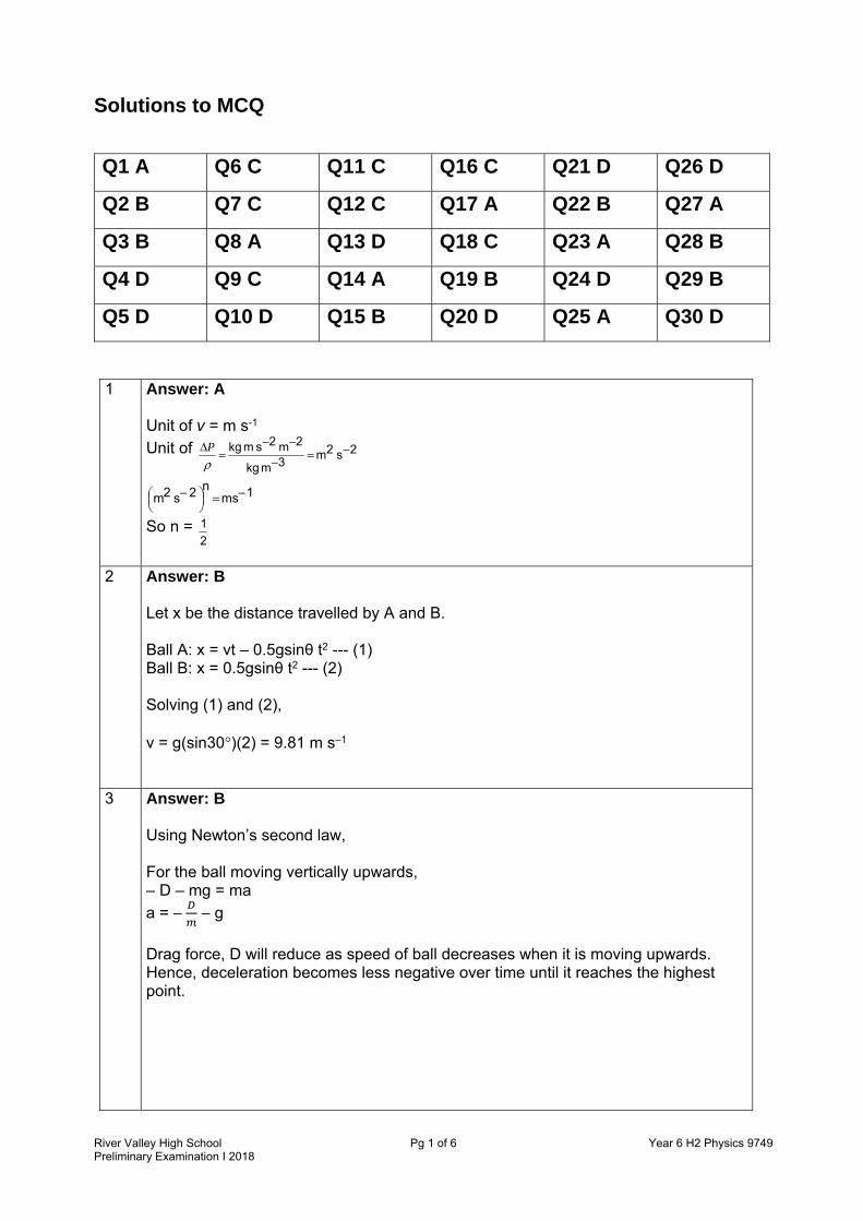
Solutions to MCQ
Q1 A Q6 C Q11 C Q16 C Q21 D Q26 D
Q2 B Q7 C Q12 C Q17 A Q22 B Q27 A
Q3 B Q8 A Q13 D Q18 C Q23 A Q28 B
Q4 D Q9 C Q14 A Q19 B Q24 D Q29 B
Q5 D Q10 D Q15 B Q20 D Q25 A Q30 D
1 Answer: A
Unit of v = m s-1
Unit of 2s2m3mkg
2m2smkg −=−
−−=Δ
ρP
1msn2s2m −=
−
So n = 2
1
2 Answer: B
Let x be the distance travelled by A and B. Ball A: x = vt – 0.5gsinθ t2 --- (1) Ball B: x = 0.5gsinθ t2 --- (2) Solving (1) and (2), v = g(sin30°)(2) = 9.81 m s–1
3 Answer: B
Using Newton’s second law, For the ball moving vertically upwards, – D – mg = ma
a = − − g
Drag force, D will reduce as speed of ball decreases when it is moving upwards. Hence, deceleration becomes less negative over time until it reaches the highest point.

River Valley High School Pg 2 of 6 Year 6 H2 Physics 9749Preliminary Examination I 2018
4 Answer: D There is no vertical resultant force when the ball is still on the surface since the normal contact force balances the weight of the ball. When the ball is in mid-air, drag force opposes the motion of the ball which decreases the vertical resultant force.
5 Answer: D Moment provided by fish = force × perpendicular distance of line of action from the pivot, P = 150 × 2.0 sin75° = 289.8 N m
6 Answer: C Since the balloon is in equilibrium, upthrust on balloon = weight of balloon and helium + force by spring = + + (1.29)(5.0) = (0.180)(5.0) + ( 3.51000) + (100)
x = 0.544 m
7 Answer: C When rocket is moving horizontally at constant speed, Thrust force F = Drag force P = Fv 28000 = 760v v = 36.84 m s–1 When rocket is moving vertically at constant speed, Thrust force F = Drag force + Weight of rocket = 760 + (90)(9.81) = 1642.9 N P = Fv = (1642.9)(36.84) = 60.5 kW
8 Answer: A When both chambers are in pressure and thermal equilibrium, = = = = ; = = =
where A is the cross-sectional area of the cylinder. Hence the ratio of the lengths is equal to the ratio of the number of mol of gases = 20 × 102845 × 104 = 0.063

River Valley High School Pg 3 of 6 Year 6 H2 Physics 9749Preliminary Examination I 2018
9 Answer: C
10 Answer: D The vertical component of the acceleration is the centripetal acceleration which is present since the particle is performing circular motion. The horizontal component of the acceleration causes the speed of the object to increase.
11 Answer: C The antenna will have the same speed as the space-craft and is still bound in orbit. There is still gravitational force acting on it which causes it to move in circular motion.
12 Answer: C Since gravitational potential energy of satellite becomes less negative, there is an increase in potential energy and the satellite is moved further from the Earth.
( )
1
1600Incre
4ase in
800
80
gravitation
al po
tentia
40 MJ kg
l
−
− − −=
=
13 Answer: D
Since v = ωx0 = 6.0 m s–1 and |a| = ω2x0 = 2.0 m s–2, ω = |a| / v = 2.0 / 6.0 = 0.333 rad s–1; T = 2π / ω = 18.9 s x0 = v / ω = 6.0 / 0.333 = 18.0 m
14 Answer: A An oscillating system will have the same frequency as that of the periodic force applied to it. Thus the system will have a frequency of 2.0 Hz after being subjected to the force (Period = 1/2.0 = 0.50 s The time taken for it to go from one maximum displacement to the next is half a period (0.50 / 2 = 0.25 s)
15 Answer: B decrease f, λ increases so more diffraction distractor C: student mixed up v = fλ decrease v, f constant, λ will decrease so less diffraction. distractor D: student may mistake larger amplitude for larger λ distractor A: decrease density, decrease speed of waves in water, same as C.
ZX is a compression at constant pressure. An adiabatic compression will be accompanied by an increase in temperature of the system while adiabatic expansion will be accompanied by a decrease in temperature of the system. If XY is an isothermal expansion, then process YZ will be moving from a point of lower temperature to higher temperature, which is true, since there is a compression.
River Valley High School Pg 4 of 6 Year 6 H2 Physics 9749Preliminary Examination I 2018
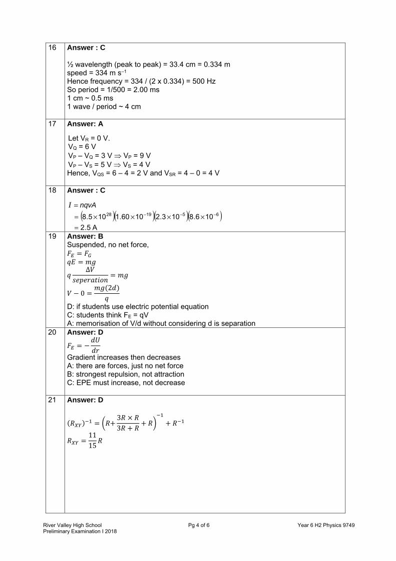
16 Answer : C ½ wavelength (peak to peak) = 33.4 cm = 0.334 m speed = 334 m s–1 Hence frequency = 334 / (2 x 0.334) = 500 Hz So period = 1/500 = 2.00 ms 1 cm ~ 0.5 ms 1 wave / period ~ 4 cm
17 Answer: A
Let VR = 0 V. VQ = 6 V VP – VQ = 3 V VP = 9 V VP – VS = 5 V VS = 4 V Hence, VQS = 6 – 4 = 2 V and VSR = 4 – 0 = 4 V
18 Answer : C
nqvA=I ( )( )( )( )
A5.2
106.8103.21060.1105.8 651928
=××××= −−−
19 Answer: B Suspended, no net force, = = ∆ = − 0 = (2 )
D: if students use electric potential equation C: students think FE = qV A: memorisation of V/d without considering d is separation
20 Answer: D = −
Gradient increases then decreases A: there are forces, just no net force B: strongest repulsion, not attraction C: EPE must increase, not decrease
21 Answer: D ( ) = + 3 ×3 + + + = 1115

River Valley High School Pg 5 of 6 Year 6 H2 Physics 9749Preliminary Examination I 2018
22 Answer: B
At null point, 12 233 E
RRRRE
++=
Hence 0.12
1 =EE
23 Answer: A = 2
onR = = 2
For F due to P = F due to Q: =
Therefore = (does not depend on IR nor direction of current)
Since IQ is twice IP, =
So position must be x to the left of P so that = 0.5
24 Answer: D
In a direction at 90° to the original path away from the wire
25 Answer: A = = 2= 2 = = 2 = 2 = 4
26 Answer: D 2 I = 2
current
B • • • • • • • B • • • • • • • B • • • • • • •
sourceIF
Irms
Irms
2
2Irms
2
4Irms
2

River Valley High School Pg 6 of 6 Year 6 H2 Physics 9749Preliminary Examination I 2018
27 Answer: A
Using KE = = , → ∝ .
= = 2.5 × 10
28 Answer: B
Using = + , , (6.63 × 10 )(3 × 10 )(80 × 10 ) = (2.6)(1.6 × 10 ) + 12 (9.11 × 10 ) = 2.1 × 10 m s–1
29 Answer: B
30 Answer: D

1
River Valley High School Page 1 of 26 Year 6 H2 Physics 9749Preliminary Examinations 2018
RIVER VALLEY HIGH SCHOOLYEAR 6 PRELIMINARY EXAMINATIONS
H2 PHYSICS 9749 / 2 PAPER 2
10 SEPTEMBER 2018
2 HOURS CANDIDATE NAME
CENTRE NUMBER
S INDEX NUMBER
CLASS 6
INSTRUCTIONS TO CANDIDATES
DO NOT OPEN THIS BOOKLET UNTIL YOU ARE TOLD TO DO SO. Read these notes carefully. Write your name, centre number, index number and class in the spaces at the top of this page and on all work you hand in. Write in dark blue or black pen on both sides of the paper. You may use an HB pencil for any diagrams or graphs. Do not use staples, paper clips, glue or correction fluid. The use of an approved scientific calculator is expected whereappropriate. Candidates answer on the Question Paper. No Additional Materials are required. Answer all questions. The number of marks is given in brackets [ ] at the end of each question or part question.
FOR EXAMINERS’ USE
Paper 2
1 / 52 / 103 / 104 / 125 / 86 / 97 / 88 / 18
Deduction
Paper 2 / 80
This document consists of 26 printed pages.

2
River Valley High School Page 2 of 26 Year 6 H2 Physics 9749Preliminary Examinations 2018
Data speed of light in free space, c = 3.00 × 10⁸ m s–1
permeability of free space, μ0 = 4π × 10–7 H m–1
permittivity of free space, ε0 = 8.85 × 10⁻¹² F m–1
= (1/(36π )) × 10–9 F m–1
elementary charge, e = 1.60 × 10⁻¹⁹ C
the Planck constant, h = 6.63 × 10⁻³⁴ J s
unified atomic mass constant, u = 1.66 × 10⁻²⁷ kg
rest mass of electron, me = 9.11 × 10⁻³¹ kg
rest mass of proton, mp = 1.67 × 10⁻²⁷ kg
molar gas constant, R = 8.31 J K–1 mol–1
the Avogadro constant, NA = 6.02 × 10²³ mol–1
the Boltzmann constant, k = 1.38 × 10⁻²³ J K–1
gravitational constant, G = 6.67 × 10⁻¹¹ N m2 kg–2
acceleration of free fall, g = 9.81 m s–2

3
River Valley High School Page 3 of 26 Year 6 H2 Physics 9749Preliminary Examinations 2018
Formulae uniformly accelerated motion 2
21 atuts +=
2 2 2v u as= +
work done on / by a gas W p V= Δ
hydrostatic pressure p ghρ=
gravitational potential φ = − GM / r temperature T / K = T / °C + 273.15
pressure of an ideal gas ><= 2
31
cV
Nmp
mean translational kinetic energy of an ideal gas molecule kTE23=
displacement of particle in s.h.m., x = x0 sin ωt velocity of particle in s.h.m., v = v0 cos ωt = )( 22
0 xx −± ω electric current, I = Anvq resistors in series, 1 2R R R= + + K resistors in parallel, 1 21/ 1/ 1/R R R= + + K
electric potential, r
QV
04πε=
alternating current/voltage, x = x0 sin ωt
magnetic flux density due to a long straight wire, d
Bπ
μ2
0 I=
magnetic flux density due to a flat circular coil, r
NB
20 Iμ=
magnetic flux density due to a long solenoid, InB 0μ=
radioactive decay, x = x0 exp (−λt)
decay constant,
2
1
2lnt
=λ

4
River Valley High School Page 4 of 26 Year 6 H2 Physics 9749Preliminary Examinations 2018
1 A student sets up the circuit shown in Fig. 1.1 in order to determine the resistivity of a piece of wire.
Fig. 1.1
(a) The following readings were obtained:
Reading of voltmeter, V
Reading of ammeter, I
Length of Wire, L
Diameter of Wire, d
1.50 ± 0.01 V 0.82 ± 0.01 A 63.2 ± 0.1 cm 0.48 ± 0.02 mm
(i) Show that the resistivity is given by ρ =
Vπd
4IL .
[1]
(ii) Hence or otherwise, calculate the resistivity of the wire together with its associated uncertainty.
resistivity = ……………………… Ω m [4]

5
River Valley High School Page 5 of 26 Year 6 H2 Physics 9749Preliminary Examinations 2018
2 (a) State the two conditions necessary for a system to be in equilibrium. 1 ……………………………………………………………………………………….…… ……………………………………………………………………………………….…….. 2 ……………………………………………………………………………………….…… ………………………………………………………………………………….……... [2]
(b) A rigid buoy is connected via an elastic rope of elastic constant 500 N m−1 vertically to the sea bed. When rope is vertical and buoy is in equilibrium, the rope has an extension of 1.80 m. Horizontal currents in the sea water travelling in the direction of left to right then cause the buoy to be displaced so that the elastic rope makes an angle of θ with the seabed. The elastic rope also extends further by 0.70 m.
(i) Sketch a free body diagram of all the forces acting on the buoy when it is
subjected to the sea currents on Fig. 2.1. Label the angle θ and forces clearly.
Fig. 2.1 [2]
(ii) Determine the magnitude of the force exerted by the elastic rope on the buoy when there are currents acting on it.
force = ……………………… N [1]
seabed
buoy

6
River Valley High School Page 6 of 26 Year 6 H2 Physics 9749Preliminary Examinations 2018
(iii) Determine the resultant of the weight and upthrust acting on the buoy. Show your working clearly
force = ……………………… N [2]
(iv) Hence, determine the magnitude of the force exerted by the currents on the
buoy.
force = ……………………… N [1]
(c) Using your values in (b), determine the angle θ.
angle = ………………………° [2]
7
River Valley High School Page 7 of 26 Year 6 H2 Physics 9749Preliminary Examinations 2018
3 (a) (i) Define gravitational potential at a point in a gravitational field.
………………………………………………………………………………………. ………………………………………………………………………………………. …………………………………………………………………………………. [1]
(ii) Explain why gravitational potential is always negative.
………………………………………………………………………………………. ………………………………………………………………………………………. ………………………………………………………………………………………. ………………………………………………………………………………………. …………………………………………………………………………………. [2]
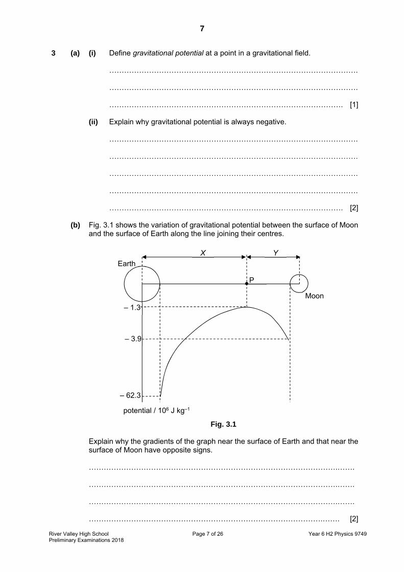
(b) Fig. 3.1 shows the variation of gravitational potential between the surface of Moon
and the surface of Earth along the line joining their centres.
Fig. 3.1
Explain why the gradients of the graph near the surface of Earth and that near the
surface of Moon have opposite signs. ……………………………………………………………………………………….……. ……………………………………………………………………………………….……. ……………………………………………………………………………………….……. ………………………………………………………………………………….……. [2]
P
X
Moon
Earth
– 62.3
potential / 106 J kg–1
– 3.9
– 1.3
Y

8
River Valley High School Page 8 of 26 Year 6 H2 Physics 9749Preliminary Examinations 2018
(c) Two moons A and B move in circular orbits about a planet, as illustrated in Fig. 3.2.
Fig. 3.2 Moon A has an orbital radius rA of 1.3 × 10⁸ m, linear speed vA and orbital period TA.
Moon B has an orbital radius rB of 2.2 × 10¹⁰ m, linear speed vB and orbital period TB.
(i) Determine the ratio A
B
v
v
ratio = ……………………… [2]

9
River Valley High School Page 9 of 26 Year 6 H2 Physics 9749Preliminary Examinations 2018
(ii) Show that A
B
T
T = 4.5 × 10⁻⁴.
[1]
(iii) The planet spins about its own axis with angular speed 1.7 × 10⁻⁴ rad s–1.
Moon A is always above the same point on the planet’s surface. Determine the orbital period TB of moon B.
TB = ……………………… s [2]
10
River Valley High School Page 10 of 26 Year 6 H2 Physics 9749Preliminary Examinations 2018
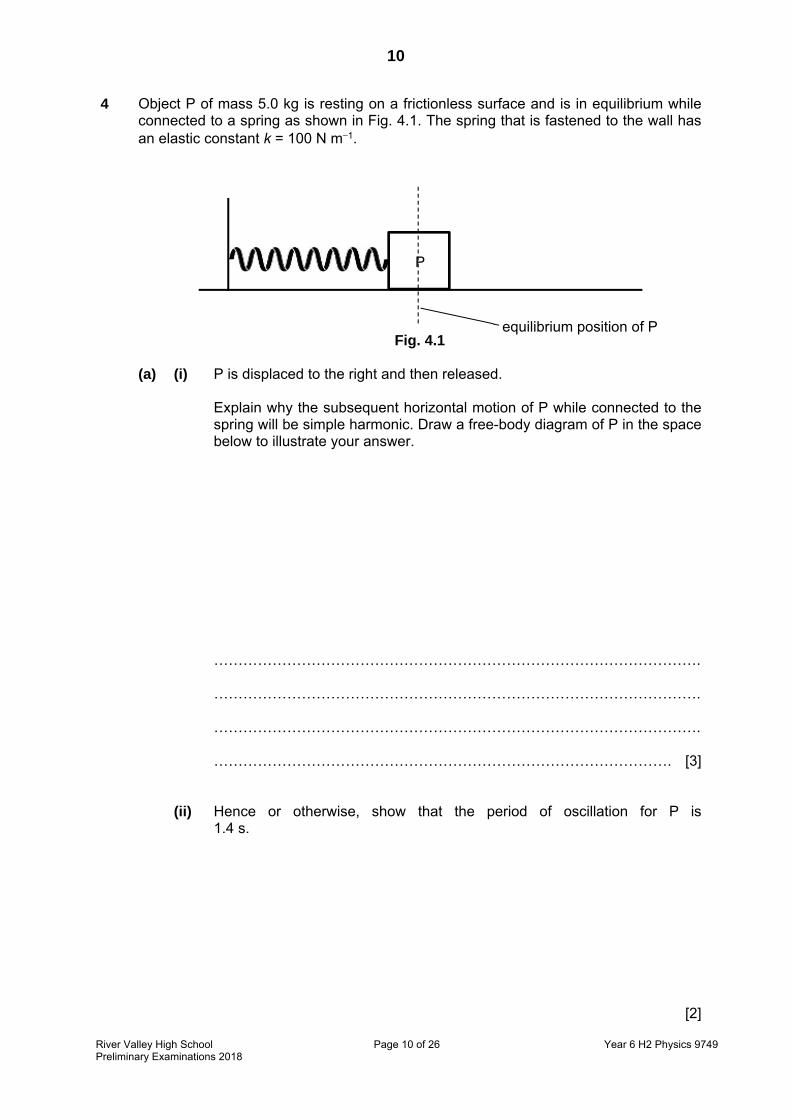
4 Object P of mass 5.0 kg is resting on a frictionless surface and is in equilibrium while connected to a spring as shown in Fig. 4.1. The spring that is fastened to the wall has an elastic constant k = 100 N m−1.
Fig. 4.1
(a) (i) P is displaced to the right and then released. Explain why the subsequent horizontal motion of P while connected to the spring will be simple harmonic. Draw a free-body diagram of P in the space below to illustrate your answer.
………………………………………………………………………………………. ………………………………………………………………………………………. ………………………………………………………………………………………. …………………………………………………………………………………. [3]
(ii) Hence or otherwise, show that the period of oscillation for P is 1.4 s.
[2]
P
equilibrium position of P

11
River Valley High School Page 11 of 26 Year 6 H2 Physics 9749Preliminary Examinations 2018
(b) A second object Q of mass 3.0 kg is slowly pushed against P, compressing the spring by 0.20 m as shown in Fig. 4.2.
Fig. 4.2
The system is then released, and both objects start moving to the right on the frictionless surface.
Fig. 4.3
(i) When P reaches the equilibrium point, Q loses contact with it and moves to the right with speed v. Determine speed v.
v = ……………………… m s−1 [2] (ii) Determine the amplitude of the oscillatory motion of P after it loses contact
with Q
amplitude = ……………………… m [1]
P Q
compression of spring = 0.20 m
equilibrium position of P
P Q
equilibrium position of P
v

12
River Valley High School Page 12 of 26 Year 6 H2 Physics 9749Preliminary Examinations 2018
(iii) Hence, determine the distance that P and Q are apart when the spring is fully stretched for the first time.
distance = ……………………… m [2]
(c) While P is oscillating about the equilibrium point, object R is dropped on it just when P is at its amplitude. R sticks to P and then moves along with P for the subsequent motion.
Fig. 4.4. Explain how the subsequent frequency and amplitude of the motion will be different.
……………………………………………………………………………………….……. ……………………………………………………………………………………….……. ……………………………………………………………………………………….……. ………………………………………………………………………………….……. [2]
P
equilibrium position of P amplitude of P
R

13
River Valley High School Page 13 of 26 Year 6 H2 Physics 9749Preliminary Examinations 2018
5 (a) Distinguish between electromotive force (e.m.f.) and potential difference (p.d.) using energy considerations.
……………………………………………………………………………………….……. ……………………………………………………………………………………….……. ……………………………………………………………………………………….……. ………………………………………………………………………………….……. [2]
(b) In order to determine the internal resistance r of a 12.00 V battery, a student sets up the circuit shown in Fig. 5.1. The variable resistor CD has a maximum resistance of 1000 Ω.
Fig. 5.1
It is found that when the sliding contact of the variable resistor is placed at C, the digital voltmeter reading is 11.99 V. When the sliding contact is moved down from C to D, the digital voltmeter reading drops from 11.99 V to 11.00 V.
(i) State the potential difference across the internal resistance of the battery
when the sliding contact of the variable resistor is placed at C.
potential difference = ……………………… V [1]
12.00 V

14
River Valley High School Page 14 of 26 Year 6 H2 Physics 9749Preliminary Examinations 2018
(ii) Explain why the presence of internal resistance in the battery reduces its output power.
………………………………………………………………………………………. ………………………………………………………………………………………. …………………………………………………………………………………. [1]
(c) (i) Using the results of (b)(i), show that R = 1199 r where R is the resistance of
the voltmeter and r is the internal resistance.
[1] (ii) Hence or otherwise, determine R and r.
R = ……………………… Ω
r = ……………………… Ω [3]

15
River Valley High School Page 15 of 26 Year 6 H2 Physics 9749Preliminary Examinations 2018
6 In a cathode ray oscilloscope, an electron beam is fired from rest, with an accelerating voltage of 1.0 kV and strikes a fluorescent screen that is 14.0 cm from the end of the vertical deflection plates as shown in Fig. 6.1. Depending on the potential difference between the horizontal and vertical deflection plates, the beam can be manipulated to draw waveforms on the screen.
Fig. 6.1 (not to scale)
An alternating voltage is applied across the vertical deflection plates. The time-base is set at 5.0 ms per division and the vertical scale of the display is set at 5.0 V per division. The waveform on the screen is shown in Fig. 6.2.
Fig. 6.2 (not to scale)
(a) Calculate the speed of the electrons just before they enter the region between the
vertical deflection plates.
speed = ……………………… m s–1 [2]
vertical deflection plates
horizontal deflection plates
fluorescent screen
undeflected electron beam
source of electron beam
6.0 cm 14.0 cm
4.0 cm

16
River Valley High School Page 16 of 26 Year 6 H2 Physics 9749Preliminary Examinations 2018
(b) Show that the time taken for an electron in the beam to travel between the vertical deflection plates is 3.2 ns.
[1]
(c) The actual applied voltage to the vertical deflection plates is 20 times that of the reading on the screen. Determine the maximum vertical deflection of the electron beam when it reaches the fluorescent screen.
maximum vertical deflection = ……………………… m [4]
(d) Describe and explain how the waveform in Fig. 6.2 would be different if the electron beam was replaced with a proton beam.
……………………………………………………………………………………….…….. ……………………………………………………………………………………….…….. ……………………………………………………………………………………….…….. ………………………………………………………………………………….…….. [2]

17
River Valley High School Page 17 of 26 Year 6 H2 Physics 9749Preliminary Examinations 2018
7 (a) In order to light up a set of lamps, each having a resistance of 20 Ω, a student sets up a circuit as shown in Fig. 7.1.
Fig. 7.1
(i) Determine the effective resistance of the circuit.
effective resistance = ……………………… Ω [1]
(ii) State and explain the relative brightness of the lamps.
………………………………………………………………………………………. ………………………………………………………………………………………. ………………………………………………………………………………………. …………………………………………………………………………………. [2]
M
N
O
P Q
S
e.m.f. E

18
River Valley High School Page 18 of 26 Year 6 H2 Physics 9749Preliminary Examinations 2018
(b) In another circuit shown in Fig. 7.2, a uniform wire AB of length 80.0 cm and resistance 1.5 Ω is connected in series with a resistor of 5.0 Ω and a cell of e.m.f. 9.0 V with internal resistance 1.0 Ω.
Fig. 7.2
(i) Calculate the potential difference across wire AB.
potential difference = ……………………… V [2]

19
River Valley High School Page 19 of 26 Year 6 H2 Physics 9749Preliminary Examinations 2018
(ii) A cell C of e.m.f. 1.5 V and internal resistance 0.80 Ω is connected to the circuit in Fig. 7.2, as shown in Fig. 7.3. The movable contact D can be connected to any point along wire AB.
Fig. 7.3 Calculate the length of AD when there is zero current in the galvanometer.
length = ……………………… m [2]
(iii) Explain what would happen to the length of AD when there is zero current in
the galvanometer, if the 5.0 Ω resistor in Fig. 7.3 is replaced by a 3.0 Ω resistor.
………………………………………………………………………………………. ………………………………………………………………………………………. ………………………………………………………………………………………. …………………………………………………………………………………. [1]

20
River Valley High School Page 20 of 26 Year 6 H2 Physics 9749Preliminary Examinations 2018
8 Read the following article and then answer the questions that follow.
Analysis of braking of a vehicle Modern vehicles are provided with different types of brakes. In cars, the foot brake is the most important in respect of control and safety of a vehicle while the hand brake is used as a reserve brake. One of the principal braking parameters of a vehicle is the deceleration a. This criterion should satisfy the following condition
a ≥[0.10 + 0.85 (φ − 0.20)] g where φ is the coefficient of cohesion and g is the acceleration due to gravity. The values of the deceleration of braking calculated according to the formula depend on the physical features of the wheel and road friction. In reference books for experts’ examination of traffic accidents as well as in scientific references on dynamics of vehicles, the provided value of coefficient of cohesion of tyres with dry asphalt is φ = 0.80. The value of the coefficient of cohesion equal to 0.80 may be applicable only to old cars and tyres produced about the year 1980. For the present-day cars, the maximum coefficient of cohesion φ is between 1.00 to 1.20, if braking takes place on dry asphalt. The anti-lock brake system (ABS) is required to ensure distribution of braking forces between the wheels to prevent the wheels from locking and therefore causing the car to skid. The majority of modern vehicles are equipped with ABS, and their real braking distance is close to the theoretically calculated one based on the maximum values of the coefficient of cohesion. So, the deceleration of such vehicles may be close to g = 9.81 m s–2. For vehicles without ABS, the deceleration will be smaller.
(a) (i) Calculate the minimum deceleration of present-day cars with ABS while
braking on dry asphalt.
minimum deceleration = ……………………….. m s–2 [1]
(ii) Assuming a car experiences constant deceleration during braking, calculate
the maximum braking distance for a present-day car travelling at 50 km/h.
braking distance = ……………………….. m [2]

21
River Valley High School Page 21 of 26 Year 6 H2 Physics 9749Preliminary Examinations 2018
(iii) State and explain whether the braking distance of a vehicle will change while braking on wet asphalt.
………………………………………………………………………………………. …………………………………………………………………………………. [1]
(iv) Suggest two disadvantages of modern vehicles that have very large deceleration when braking if travelling on an expressway.
………………………………………………………………………………………. ……………………………………………………………………………………….
………………………………………………………………………………………. …………………………………………………………………………………. [2]
(b) A car has two important braking devices and they function independently. The foot brake is operated by foot and the hand brake is operated by hand. When a car has a brake test, two sets of measurements are made:
1. The maximum braking force on the wheels produced by operating the foot brake.
2. The maximum braking force produced by operating the hand brake. Typical data for a car of mass 900 kg are as follows.
Description Maximum braking
force / N
Foot brake 6700
Hand brake 2000
In order to determine whether or not the brakes are satisfactory, the data are applied to a chart (called a nomogram) like the one shown in Fig. 8.1. This chart has three vertical lines marked with scales.

22
River Valley High School Page 22 of 26 Year 6 H2 Physics 9749Preliminary Examinations 2018
braking efficiency and stopping distance from 20 m s–1
Fig. 8.1
The central vertical line is for the maximum braking force. The left line is for the mass of the car. The right line is for the braking efficiency and also for the stopping distance from an initial speed of 20 m s–1. The braking efficiency E is defined by the equation
E= deceleration of car
acceleration of free fall ×100
As an example of the use of this chart for the car of mass 900 kg, the figures in the table show a maximum braking force for the foot brake of 6700 N. The point A corresponding to the mass and the point B corresponding to the braking force are joined to give a straight sloping line. This line is extended to cut the braking efficiency scale at the point C, and shows that in this particular case the stopping distance S from a speed of 20 m s–1 is about 27 m.
Mass of car M / kg
Maximum braking force
F / N
Braking efficiency %
Stopping distance from a speed
of 20 m s−1 S / m
23
River Valley High School Page 23 of 26 Year 6 H2 Physics 9749Preliminary Examinations 2018
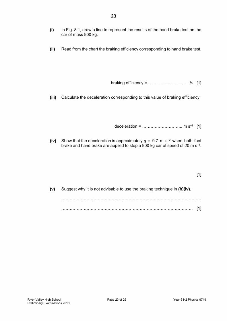
(i) In Fig. 8.1, draw a line to represent the results of the hand brake test on the car of mass 900 kg.
(ii) Read from the chart the braking efficiency corresponding to hand brake test.
braking efficiency = ……………………….. % [1]
(iii) Calculate the deceleration corresponding to this value of braking efficiency.
deceleration = ……………………….. m s–2 [1]
(iv) Show that the deceleration is approximately g = 9.7 m s–2 when both foot brake and hand brake are applied to stop a 900 kg car of speed of 20 m s–1.
[1]
(v) Suggest why it is not advisable to use the braking technique in (b)(iv).
………………………………………………………………………………………. …………………………………………………………………………………. [1]

24
River Valley High School Page 24 of 26 Year 6 H2 Physics 9749Preliminary Examinations 2018
(c) Now consider a car of mass 1300 kg. The data for maximum braking force and stopping distance from 20 m s–1 are given in Fig. 8.2.
F / N s / m
3000 88.0
4000 66.0
5000 54.0
6000 45.0
7000
8000 32.5
10000 27.0
12000 23.0
Fig. 8.2
(i) Use Fig. 8.1 to determine the stopping distance when F = 7000 N. Show your construction on Fig. 8.1.
stopping distance = ……………………….. m [1]
(ii) On Fig. 8.3, plot the point corresponding to F = 7000 N and draw the line of best fit for all the points. [1]

25
River Valley High School Page 25 of 26 Year 6 H2 Physics 9749Preliminary Examinations 2018
Fig. 8.3
F / kN 0 2 4 6 8 10 12 14
10
0
20
30
40
50
60
70
80
90
s / m

26
River Valley High School Page 26 of 26 Year 6 H2 Physics 9749Preliminary Examinations 2018
(iii) Use Fig. 8.3 to determine the work done when the maximum braking force is 9000 N. State any assumptions made in your calculations.
work done = ……………………….. J
………………………………………………………………………………………. …………………………………………………………………………………. [2]
(d) (i) A passenger of mass 70 kg was not wearing a seat belt and was sleeping at the front seat of a car. The car of mass 1300 kg was travelling at 20 m s−1 when a maximum braking force of 12000 N was applied on it. Using Fig. 8.1 and the equation for braking efficiency, determine the minimum force that the passenger would have to apply to prevent himself from flying off the seat. Show your working clearly.
force = ……………………….. N [3]
(ii) Suggest whether the passenger would be able to prevent himself from flying off the seat.
……………………………………………………………………………………….
………………………………………………………………………………………. …………………………………………………………………………………. [1]
END OF PAPER

PRELIMINARY EXAMINATIONS 2018
H2 PHYSICS 9749/2 MARKSCHEME
1 (a)
IVR = and
ALR ρ= , hence
AL
IV ρ=
4ILπVd
ILVAρ
2
==
(b)
632.082.04)1048.0(50.1
4
232
×××××==
−ππρILVd
Ω×= −71023.5 m
dd
LL
II
VV Δ+Δ+Δ+Δ=Δ 2
ρρ
1037.048.002.02
2.631.0
82.001.0
50.101.0 =+++=
71023.51037.01037.0 −××==Δ ρρ Ω×≈×= −− 77 105.01054.0 m
Hence, ( ) Ω100.55.2 7−×±=ρ m
2 (a) Conditions for equilibrium:
1. The net/resultant force acting on the body must be zero.
= 0F -- Translational Equilibrium
2. The net/resultant torque about any point must be zero.
= 0τ -- Rotational Equilibrium
No marks awarded if only equations are given.
(b) (i)
Fig. 2.1 Correct directions (components of the forces should be in all 4 directions) and θ Correct labelling for the forces identified
seabed
buoy
tension
upthrust
weight
force by currents
θ

Approximate length in both vertical and horizontal directions are the same, both marks awarded. If not, deduct 1.
(ii) F = kx = 500 × 2.5 = 1250 N
(iii) When the buoy was initially at equilibrium, the resultant of the weight and upthrust is equal to the tension by the rope; T + W = U → U – W = T Fresultant = kx = 500 × 1.8 = 900 N
(iv) The tension by the rope in (b)(ii) is equal in magnitude to the resultant of the force by currents, weight and upthrust Force by currents = √1250 − 900 = 867.5 N = 868 N ( 3 s.f.)
(c) θ = tan−1 (900/867.5)
= 46.1° (3 s.f.) If a different θ is labelled in previous diagram, e.c.f.
3 (a) (i) Gravitational potential at a point is defined as work done per unit mass by an external agent to move a test mass from infinity to that point in the gravitational field (without a change in kinetic energy)
(ii) Gravitational potential at infinity is defined as zero and since gravitational force is attractive,
work done by external agent to move an object from infinity to a point in the gravitational field is negative, so potential is negative
(b) The gradient of the potential–displacement graph gives the gravitational field strength, which is a vector, thus, the sign indicates the direction of the gravitational field strength
Near the earth, the net gravitational field strength is directed towards the earth due to its larger influence than the moon while near the moon, the net gravitational field strength is directed towards the moon due to its larger influence. Hence, their sign are opposite
(c) (i) 1. Since the gravitational force the planet exert on moon A and B provides the centripetal force for them to rotate about the planet, = ( together with statement for B1)

= 1
Since GMP are constant, vA
2 α 1/r,
vA / vB = (rB / rA)1/2
= (2.2 × 10¹⁰/ 1.3 × 10⁸)1/2
= 13 (13.0)
Fractions not accepted
2. v = 2πr / T
v ∝ r / T
TA / TB = (rA / rB) × (vB / vA)
= (1.3 × 10⁸ / 2.2 × 1010) × (1 / 13)
= 4.5 (4.54) × 10–4
(ii) T = 2π / 1.7 ×10–4 = 3.70 × 10⁴ s
TB = 3.70 × 10⁴ / 4.54 × 10–4
= 8.1 × 10⁷ s

4 (a) (i) ma = − kx a = − (k / m) x Since the resultant force on P is the elastic force by the spring, the acceleration on P is directly proportional to the displacement of P from the equilibrium position. Or tension is directly proportional to displacement from equilibrium position and is the resultant force (Second B1 mark) The negative sign also shows that the direction of acceleration is always directed towards the equilibrium position.
(ii) = = 2
= 2 5100
= 1.405 s = 1.4 (2 s.f.)
(b) (i) Loss in elastic potential energy = Gain in kinetic energy
12 = 12 ( + ) 12 (100)(0.2) = 12 (5.0 + 3.0) = 0.707
tension
normal reaction force
weight

(ii) Gain in elastic potential energy = Loss in kinetic energy 12 = 12 12 (100)( ) = 12 (5.0)(0.707) = 0.158 OR = 0.7071 = 21.405 = 0.158
(iii) Distance travelled by Q in quarter of a period = 0.707 × 0.25(1.405) = 0.2484 m Distance apart = 0.2484 – 0.1581 = 0.0903 m = 0.090 m (2 s.f.)
(c) The frequency will be lower since period will be longer according to = 2
Amplitude will be same since maximum elastic potential energy of system remains the same.
5 (a) E.m.f. is the amount of energy transferred from non-electrical forms to electrical energy per unit charge as it passes through a complete circuit while p.d. is the amount of electrical energy converted to other forms per unit charge delivered between 2 points.
(b) (i) 0.01 V (ii) Internal resistance reduces the terminal potential difference of the
battery. Since the output power is proportional to its terminal p.d., the presence of internal resistance reduces the output power of the battery. OR There is some power loss due to power dissipated due to the internal resistance.
(c) (i) 12.00 = I1 (r +R) where I1 r = 0.01 V and I1 R = 11.99 V
Hence R = 1199 r,
(ii) Also 12.00 = I2 (r + R + 1000) where I2 R = 11.00 V Using R = 1199 r, Hence I2 (1199 r) = 11.00 V I2 r = 0.009174 V 1000 I2 = 12.00 – 11.00 - 0.009174 = 0.9908 V I2 = 9.908 x 10⁻⁴ A

From 12.00 = 9.908 x 10⁻⁴ (r + 1199 r + 1000) r = 9.26 Ω And R = 11100 Ω
6 (a) Loss in EPE of the E- field = Gain in KE of the electron = 12 = = ( . × )( )( . × ) = 1.8742 × 10 m s–1 = 1.87 × 10 m s–1
(b) constant horizontal velocity as no horizontal accelerating forces (for
vertical plates) (similar to projectile motion where horizontal velocity is usually constant).
time taken = . ×. × = 3.20 ns (3 sf) = 3.2 ns (2 sf)
Must show substitution and +1 sf to get M1 Allow e.c.f.
(c) Actual p.d. across plates = 5.0 × 20 = 100 V
Electric field strength = = . × = 2500 N C–1
Vertical acceleration = = ( . × )( ). × = 4.390770 × 10 m s–2
Vertical velocity upon exiting vertical deflection plates = + = (4.39 × 10 )(3.2 × 10 ) = 1.405 × 10 m s–1
Time taken for rest of 14 cm = ×. × = 7.470 × 10 s
Vertical displacement for first 6.0 cm
= = (4.390770 × 10 )(3.2 × 10 ) = 2.248 × 10 m
Vertical displacement for next 14.0 cm = = (1.405 × 10 )(7.470 × 10 ) = 1.0495 × 10 m Distance between vertical divisions = 1.0495 × 10 + 2.248 × 10 = 1.274 × 10 m = 1.3 × 10 m

(d) • smaller amplitude / deflection • because same charge, same force, but larger mass (1000x), so
deflection would be smaller OR • waveform is compressed horizontally • because same charge, same force, but larger mass (1000x), so the
applied voltage will not be sufficient to deflect the electron beam to the extreme ends.
OR • waveform is inverted / reflected about the x-axis (timebase axis) and y-
axis (voltage gain axis) • because opposite charge, deflection will be in the opposite direction
7 (a) (i) Since the 4 branches have the same p.d., they are in parallel arrangement. 1 = 120 + 140 + 120 + 140
= 6.66 Ω
(ii) Consider power delivered to each of the lamps,
=
For M and P, =
Consider lamps N, O, Q and S individually,
= ( . )
Therefore M and P are brightest, N, O, Q and S are less bright (quarter brightness)
(b) (i) Using potential divider rule, 1.51.0 + 5.0 + 1.5 9.0 = = 1.8 V
(ii) 0 A in galvanometer: = 1.5 V
Using potential divider rule,
1.51.8 = 0.800
= 0.67 m
(iii) When the 5.0 Ω resistor is replaced by a 3.0 Ω resistor, the p.d. across wire AB will be larger than 1.8 V and hence the balance length of AD will be shorter than in (b)(ii).

8 (a) (i) ax = 0.1 + 0.85(1.0 – 0.2) .g = 7.65 = 7.7 m s−2 (ii) Using = + 2 ,
0 = + 2(−7.65) = 12.61 = 12.6
(ii) The minimum deceleration will decrease as wet surfaces reduce the
frictional force acting on the tyre. Hence, the braking distance will increase.
(iv) • Driver and passagers may experience discomfort in travelling in
the vehicle. • Tailgating vehicles may not brake in time and may result in
collision. • Tyre will wear out faster.
(b) (i)
(ii) 22 % , [or 22.5%]

(iii) 22 = (deceleration/9.81) x 100
deceleration = 2.16 m s-2
or
F = ma
2000 = 900 a
a = 2.22 m s-2
(iv) Using F = ma,
6700+2000 = (900)a
a = 9.67 m s-2 = 9.7 m s-2
(v) Not advisable.
• The driver needs to use both his hands to control the steering wheel when braking at high speed. Hence, he should not use his hand to activate the handbrake.
• The car may skid as the car is not designed for both foot brake and hand brake to be used at the same time.
(c) (i) 38.0 m [allow 37.0 m to 39.0 m] (ii) Point plotted correctly with best fit line drawn (iii) Explain that work done is product of force and displacement
coordinates in the graph. The coordinate is (9000, 29) Work done = 9000 x 29 = 2.61 x 10⁵ J [to present answer in standard form] Assumption: the braking force is constant throughout the deceleration.
(d) (i) Using Fig. 8.1, the braking efficiency is 87.5% for braking force of
12000 N. [allow 85% to 90%] Hence, the deceleration of car = 0.875 x 9.81 = 8.58 m s-2 Force = ma = (70)(8.58) = 600 N
(ii) v = u + at ,
0 = 20 + (-8.58)t t = 2.3 s

The reaction time for the passengers could be longer than 2.3 s as he was sleeping and would not be able to react quickly when the car was braking.
OR
The force to restrain the passage could be too large at 600N.

1
River Valley High School Page 1 of 26 Year 6 H2 Physics 9749Preliminary Examinations 2018
RIVER VALLEY HIGH SCHOOLYEAR 6 PRELIMINARY EXAMINATIONS
H2 PHYSICS 9749 / 3 PAPER 3
14 SEPTEMBER 2018
2 HOURS
CANDIDATE NAME
CENTRE NUMBER
S INDEX NUMBER
CLASS 6
INSTRUCTIONS TO CANDIDATES
DO NOT OPEN THIS BOOKLET UNTIL YOU ARE TOLD TO DO SO.
Read these notes carefully. Write your name, centre number, index number and class in thespaces at the top of this page and on all work you hand in. Candidates answer on the Question Paper. Write in dark blue or black pen on both sides of the paper. You may use an HB pencil for any diagrams or graphs. Do not use staples, paper clips, glue or correction fluid. The use of an approved scientific calculator is expected, where appropriate. Section A Answer all questions. Section B Answer one question only. You are advised to spend one and half hours on Section A and half an hour on Section B. The number of marks is given in brackets [ ] at the end of each question or part question.
This document consists of 25 printed pages and 1 blank page.
FOR EXAMINERS’ USE Section A – do all questions
1 / 62 / 163 / 64 / 105 / 126 / 10
Section B – do ONE question only
7 / 208 / 20
Deduction
TOTAL / 80

2
River Valley High School Page 2 of 26 Year 6 H2 Physics 9749Preliminary Examinations 2018
Data speed of light in free space, c = 3.00 × 10⁸ m s–1
permeability of free space, μ0 = 4π × 10–7 H m–1
permittivity of free space, ε0 = 8.85 × 10⁻¹² F m–1
= (1/(36π )) × 10–9 F m–1
elementary charge, e = 1.60 × 10⁻¹⁹ C
the Planck constant, h = 6.63 × 10⁻³⁴ J s
unified atomic mass constant, u = 1.66 × 10⁻²⁷ kg
rest mass of electron, me = 9.11 × 10⁻³¹ kg
rest mass of proton, mp = 1.67 × 10⁻²⁷ kg
molar gas constant, R = 8.31 J K–1 mol–1
the Avogadro constant, NA = 6.02 × 10²³ mol–1
the Boltzmann constant, k = 1.38 × 10⁻²³ J K–1
gravitational constant, G = 6.67 × 10⁻¹¹ N m2 kg–2
acceleration of free fall, g = 9.81 m s–2

3
River Valley High School Page 3 of 26 Year 6 H2 Physics 9749Preliminary Examinations 2018
Formulae
uniformly accelerated motion 221 atuts +=
2 2 2v u as= +
work done on / by a gas W p V= Δ hydrostatic pressure p ghρ= gravitational potential φ = − GM / r temperature T / K = T / °C + 273.15
pressure of an ideal gas ><= 2
31
cV
Nmp
mean translational kinetic energy of an ideal gas molecule kTE23=
displacement of particle in s.h.m., x = x0 sin ωt velocity of particle in s.h.m., v = v0 cos ωt = )( 22
0 xx −± ω electric current, I = Anvq resistors in series, 1 2R R R= + + K resistors in parallel, 1 21/ 1/ 1/R R R= + + K
electric potential, r
QV
04πε=
alternating current/voltage, x = x0 sin ωt
magnetic flux density due to a long straight wire, d
Bπ
μ2
0I=
magnetic flux density due to a flat circular coil, r
NB
20 Iμ=
magnetic flux density due to a long solenoid, InB 0μ=
radioactive decay, x = x0 exp (−λt) decay constant,
2
1
2lnt
=λ

4
River Valley High School Page 4 of 26 Year 6 H2 Physics 9749Preliminary Examinations 2018
Section A
Answer all the questions in this Section in the spaces provided.
1 (a) An object of mass m is accelerated by a constant resultant force from rest to a speed v. By considering the work done on it, with reference to equations of motion, derive an expression for its kinetic energy Ek.
[3] (b) A car of mass 820 kg is travelling at constant speed along a horizontal road. The engine
of the car provides 37 kW and a constant drag force of 1.2 kN acts on the car throughout its motion.
(i) Show that the work done in overcoming the drag force during a time of 11 s is 410 kJ.
[1] (ii) Calculate the maximum speed that the car can travel at if the engine provides half
the original power. Show your working clearly.
maximum speed = ……………………… m s−1 [2]

5
River Valley High School Page 5 of 26 Year 6 H2 Physics 9749Preliminary Examinations 2018
2 (a) The first law of thermodynamics states that the increase in internal energy of a closed system is the sum of the heat supplied and work done on the system. Explain what is meant by
(i) internal energy,
……………………………………………………………………………………………… ……………………………………………………………………………………………… ……………………………………………………………………………………………… ……………………………………………………………………………………….. [1] (ii) closed system,
……………………………………………………………………………………………… ……………………………………………………………………………………….. [1] (iii) heat.
……………………………………………………………………………………………… ……………………………………………………………………………………….. [1] (b) (i) An ideal gas occupies a volume V at a pressure p and a temperature of T inside
an insulated container as shown in Fig. 2.1. It is held in place by a frictionless piston. The other section of the container contains a vacuum. Using the first law of thermodynamics, explain why the temperature of the gas remains constant when the piston is no longer held in place and the gas is allowed to expand to occupy the entire volume of the container.
Fig. 2.1
……………………………………………………………………………………………… ……………………………………………………………………………………………… ……………………………………………………………………………………………… ……………………………………………………………………………………….. [3]
vacuum, volume 2V
pressure p, volume V
moveable piston, initially held in place
insulated container

6
River Valley High School Page 6 of 26 Year 6 H2 Physics 9749Preliminary Examinations 2018
(ii) Hence or otherwise, determine the ratio of the initial pressure to the final pressure of the gas.
ratio = ……………………… [2] (c) In 1816, Robert Stirling patented the Stirling engine which operates by cyclic compression
and expansion of air or other gas at different temperatures, such that there is a net conversion of thermal energy to mechanical work. Figure 2.2 shows the cycle of changes that a gas undergoes in the Stirling engine.
Fig. 2.2 Fig. 2.3 shows the processes that are involved in the cycle of changes.
section of cycle
description heat supplied
A → B increase of volume at constant temperature
B → C decrease of pressure at constant volume
C → D decrease of volume at constant temperature
D → A increase of pressure at constant volume
Fig. 2.3
(i) Complete the table in Fig. 2.3 by writing ‘to’ or ‘from’. [2]
pressure
volume
A
B
C
D
V 2V
3T
T

7
River Valley High School Page 7 of 26 Year 6 H2 Physics 9749Preliminary Examinations 2018
(ii) Determine, in terms of n, R and T, the change in internal energy for n mol of a monatomic ideal gas for the change D → A.
[1] (iii) The work done on the gas for a change in volume at constant temperature can be
given by the expression W = n R T lnVinitial
Vfinal.
Hence or otherwise, derive an expression for the net heat transferred to the gas during one cycle in terms of n, R and T. Explain your working clearly.
[3] (iv) The efficiency of the Stirling engine shown is determined by the net work done by
the system divided by the heat transferred to the system. Using your working in (c)(i) to (iii), determine the efficiency.
efficiency = …………………… [2]

8
River Valley High School Page 8 of 26 Year 6 H2 Physics 9749Preliminary Examinations 2018
3 A 0.050 kg mass is attached to one end of an elastic string of unstretched length 0.50 m. The other end of the string is attached to a fixed support. The force constant of the elastic string is 40 N m–1. The mass is rotated steadily on a smooth table in a horizontal circle of radius 0.70 m as shown in Fig. 3.1.
Fig. 3.1
Fig. 3.2 shows the side view of the string and mass.
(a) On Fig. 3.2, draw and identify the forces acting on the mass. [2] (b) Calculate the linear speed of the mass.
linear speed = ……………………… m s–1 [2] (c) The mass is now rotated at a speed v in a vertical plane of radius r. Derive an expression,
in terms of r, for the minimum speed at the highest point of the circular path at which the string just becomes slack.
[2]
table top
side view
Fig. 3.2
fixed support
0.70 m
plan view

9
River Valley High School Page 9 of 26 Year 6 H2 Physics 9749Preliminary Examinations 2018
4 A cyclotron uses a magnetic field to maintain alpha particles in nearly circular paths. Electromagnets with ferrous cores provide the required strong magnetic field as shown in Fig. 4.1.
Fig. 4.1
The ions, originating from a source at the centre, released from rest, move within two D-shaped hollow electrode chambers called dees, separated by a very narrow gap. Each time the ions pass into the gap between the dees, they are subjected to a potential difference applied between the dees, subsequently increasing the radius of curvature of their path. After many revolutions, the ions acquire high speeds and reach the outer edge of the cyclotron.
(a) State what is meant by a magnetic field. ………..……………………………………………………………………………………………. …………………………………..…………………………………………………………... [1] (b) On Fig. 4.1, draw arrows to indicate the direction of magnetic flux density provided by the
electromagnets. [1]
electromagnet with ferrous core
electromagnet with ferrous core
gap where potential difference is applied
hollow electrode chambers
alpha particle released at source from rest
alternating current source to provide changing p.d.
particle’s path (anti-clockwise)
target at exit of cyclotron

10
River Valley High School Page 10 of 26 Year 6 H2 Physics 9749Preliminary Examinations 2018
(c) (i) By considering the path taken by the alpha particles and forces acting on them in the cyclotron, derive an expression for the radius of curvature r of the path. Express your answer in terms of mass of ions, charge, linear speed v, and magnetic flux density B. Charge should be in terms of elementary charge e and mass in terms of unified atomic mass constant u. Show your working clearly.
[2] (ii) Hence, explain why the radius increases each time after the ions pass between the
dees.
……………………………………………………………………………………………… ……………………………………………………………………………………………… ……………………………………………………………………………………….. [1] (d) The magnetic flux density in the dees provided by the electromagnets is equivalent to
that at the centre of a solenoid of length 0.39 m, 3100 turns, and a current of 200 A flowing in it. Show that the magnetic flux density in the dees is 2.0 T.
[1]

11
River Valley High School Page 11 of 26 Year 6 H2 Physics 9749Preliminary Examinations 2018
(e) The potential difference between dees varies periodically as shown in Fig. 4.2.
Fig. 4.2
The alpha particles reach an energy of 16 MeV after accelerating within the cyclotron for a duration of 0.52 ms and exiting the cyclotron at a radius of 0.29 m. Determine the potential difference between the dees at each crossing.
potential difference = ……………………… V [4]
time / s
potential difference / V

12
River Valley High School Page 12 of 26 Year 6 H2 Physics 9749Preliminary Examinations 2018
5 (a) In order to investigate the photoelectric effect, a student set up the apparatus illustrated in Fig. 5.1.
Fig. 5.1
The wavelength of the radiation incident on the zinc plate was varied. For two values of
wavelength λ, the stopping voltage Vs required just to prevent electrons reaching the gauze was measured. The results are shown in Fig. 5.2.
Fig. 5.2 (i) Define work function energy. ……………………………………………………………………………………………… ……………………………………………………………………………………….. [1] (ii) Calculate the maximum speed of a photoelectron emitted from the metal surface
by radiation of 380 nm.
maximum speed = ……………………… m s–1 [2]
gauze
zinc plate
radiation
0
0.25
0.50
0.75
1.00
Vs / V
350 400 450 500 550 λ / nm

13
River Valley High School Page 13 of 26 Year 6 H2 Physics 9749Preliminary Examinations 2018
(iii) Calculate the work function energy of the metal surface.
work function energy = ……………………… eV [2] (iv) Suggest why it is not possible to deduce the threshold wavelength of this metal
surface directly from Fig. 5.2, without further calculations.
……………………………………………………………………………………………… ……………………………………………………………………………………….. [1] (b) In order to investigate the X-ray spectrum of a particular target metal, the student uses
an X-ray tube where high energy electrons are fired on the target metal. Fig 5.3 shows a sketch of the X-ray spectrum produced for the target metal. The tube voltage is 100 kV.
Fig. 5.3 The energy required to remove an electron from the various shells of the target metal atom is shown in Fig. 5.4.
type of shell energy / 10−15 J
K 1.4
L 0.27
M 0.12
Fig. 5.4
intensity
photon energy 0 0

14
River Valley High School Page 14 of 26 Year 6 H2 Physics 9749Preliminary Examinations 2018
(i) Given that the two sets of peaks in Fig. 5.3 correspond to the K and L spectrum lines, label Kα and Lβ. [1]
(ii) On Fig. 5.3, sketch a spectrum for X-ray from the tube if the tube voltage is halved. [1] (iii) Calculate the energy of the X-ray photon of longest wavelength in the K-spectrum
of the target metal.
energy = ……………………… eV [2] (iv) Explain the formation of Kβ spectrum lines. ……………………………………………………………………………………………… ……………………………………………………………………………………………… ……………………………………………………………………………………………… ……………………………………………………………………………………….. [2]

15
River Valley High School Page 15 of 26 Year 6 H2 Physics 9749Preliminary Examinations 2018
6 The table shows the half-life of various radioactive nuclides.
nuclide Po84
197 Rn86
220 Ra88
222 Pa91
234
half-life / s 60 52 38 70
The variation of the number of nuclei with time for one of these radioactive nuclides is shown in Fig. 6.1.
Fig. 6.1
(a) (i) Using Fig. 6.1, determine which is the decaying radioactive nuclide. Show your
working clearly.
decaying radioactive nuclide = ……………………… [3]
number of nuclei / 1020

16
River Valley High School Page 16 of 26 Year 6 H2 Physics 9749Preliminary Examinations 2018
(ii) Hence, calculate the initial activity of the radioactive nuclide.
initial activity = ……………………… Bq [2] The decaying radioactive nuclide emits an alpha particle as it decays into a stable daughter
nuclide Y.
(b) By plotting 3 points on Fig. 6.1, sketch a graph of the variation of number of daughter nuclide Y with time. Show your working clearly.
[2] (c) Write a complete nuclear equation for the decay process.
[1] (d) Given that linear momentum is conserved in this decay, show that the ratio
initial kinetic energy of -particle
initial kinetic energy of daughter nucleus Y = ¼ A – 1 where A is the nucleon number of the
decaying radioactive nuclide.
[2]

17
River Valley High School Page 17 of 26 Year 6 H2 Physics 9749Preliminary Examinations 2018
Section B
Answer one question in this section in the spaces provided.
7 (a) A glass tube, open at both ends, has fine dust sprinkled along its length. A sound source is placed near one open end of the tube, as shown in Fig. 7.1.
Fig. 7.1 (i) On Fig. 7.1, sketch the form of the stationary wave set up in the tube and mark,
with the letter A, the position(s) of any displacement antinode(s) of the stationary wave. [2]
(ii) The distance between six heaps, as shown in Fig. 7.1, is 39.0 cm.
Show that the wavelength of the stationary wave is 15.6 cm.
[1] (iii) The frequency at which these heaps are formed is 2.14 kHz.
Calculate the speed of sound in the tube.
speed = ……………………… m s–1 [2] (iv) State the fundamental frequency at which a stationary wave can be set up in the
tube.
fundamental frequency = ……………………… Hz [3]
glass tube

18
River Valley High School Page 18 of 26 Year 6 H2 Physics 9749Preliminary Examinations 2018
(v) State and explain the change, if any, to the dust heaps if the right open end of the tube is blocked with a lid, keeping the frequency at 2.14 kHz.
…………………………………………………………………………………………….. ………………………………………………………………………………………. [2] (b) Fig. 7.2 shows an arrangement used to determine the speed of microwaves in the
laboratory.
Fig. 7.2
A stationary wave is formed between the metal plate and the transmitter. As the detector is moved along a line between the transmitter and the point M, it registers a series of high intensity signals. The positions of these high intensity signals are marked by crosses on an axis as shown in in Fig. 7.3.
Fig. 7.3
(i) State the phase difference between points A and B. phase difference = ……………………… rad [1] (ii) The transmitter emits microwaves of frequency 10 GHz.
Use Fig. 7.3 to deduce an experimental approximation for the speed of the microwaves.
speed of microwaves = ……………………… m s–1 [2]
A B

19
River Valley High School Page 19 of 26 Year 6 H2 Physics 9749Preliminary Examinations 2018
(iii) The detector is now fixed at a position of high intensity. If the metal plate is moved away from transmitter at a speed of 1.0 cm s–1 while the detector is kept stationary, determine the frequency of the high intensity signals registered on the detector.
frequency = ……………………. Hz [2] The metal plate is now removed from the arrangement and a sheet of hardboard is
inserted between the detector and the transmitter without either of these being moved as shown in Fig. 7.4. The hardboard is a soft boundary that partially reflects microwaves.
When the hardboard is inserted, the intensity of the wave drops to 1
16th of its original
value.
Fig. 7.4
(iv) Calculate the ratio of amplitude of detected wave after hardboard insertion
amplitude of detected wave before hardboard insertion.
ratio = ……………………… [2]
hardboard (partial reflector)

20
River Valley High School Page 20 of 26 Year 6 H2 Physics 9749Preliminary Examinations 2018
The metal plate is now placed back in original position as shown in Fig. 7.5.
Fig. 7.5
(v) Fig. 7.6 shows the variation of intensity with position as the detector is moved
between the transmitter and M at a particular frequency before the hardboard is inserted. Sketch on Fig. 7.6 the variation of intensity with position as the detector is moved between the hardboard and M after the hardboard is inserted.
Fig. 7.6
[3]
hardboard (partial reflector)
point M hardboard
intensity / arbitrary units
original intensity

21
River Valley High School Page 21 of 26 Year 6 H2 Physics 9749Preliminary Examinations 2018
8 A typical three-phase generator in turbines use for power generation consists of a rotating electromagnet surrounded by three sets of stationary wire coils AA’, BB’, CC’, with angles of 120˚ between them, wrapped around metal cores to generate electricity, as shown in Fig. 8.1.
Fig. 8.1 Each set of coils (AA’, BB’, CC’) is a solenoid that consists of wires tightly wound around a rigid metal core as shown in Fig. 8.2.
Fig. 8.2 The electromagnet shown in Fig. 8.1 can rotate about the axis perpendicular to the plane of the page, and is connected to turbine blades that rotate the electromagnet at a constant rate such that electricity can be generated in the coils.
(a) State Faraday’s law of electromagnetic induction.
……………………………………………………………………………………………………... ……………………………………………………………………………………………………... ……………………………………………………………………………………………….. [2]
wire coil
metal core
wire coil wrapped around a metal core
rotating electromagnet
C’
A
B
A’
B’ C
three phase output

22
River Valley High School Page 22 of 26 Year 6 H2 Physics 9749Preliminary Examinations 2018
(b) (i) Ignoring coils B and C, explain why the rotation of the electromagnet causes a sinusoidal e.m.f. to be induced in coil A.
……………………………………………………………………………………………… ………………………………………………………………………………………………
……………………………………………………………………………………………… ……………………………………………………………………………………………… ………………………………………………………………………………………… [3] (ii)
Fig. 8.3
At a particular instant, at time t = 0 s, the magnet is aligned with the set of coils labelled AA’ as shown in Fig. 8.3. Set AA’ has a total of 500 turns with a diameter 0.10 m. The electromagnet generates an effective uniform magnetic flux density of 0.80 T at the position of the coils when its axis aligns with that of the coils. Calculate the magnetic flux linkage of the coils at this instant. Give an appropriate unit.
magnetic flux linkage = ……………………………. [3]
A
three phase output
B’
C’ B
C
A’

23
River Valley High School Page 23 of 26 Year 6 H2 Physics 9749Preliminary Examinations 2018
(iii) The variation with time of magnetic flux linkage of the coil is as shown in Fig. 8.4. The flux linkage varies sinusoidally with time.
Fig. 8.4
When operating optimally, the magnet makes 1800 revolutions per minute.
Write an expression for the magnetic flux linkage in the coil as a function of time t as shown in Fig. 8.4.
[1] (iv) Hence, show that the maximum induced e.m.f. in the coil is 590 V.
[2]
0 t / s
T 2T

24
River Valley High School Page 24 of 26 Year 6 H2 Physics 9749Preliminary Examinations 2018
(v) On Fig. 8.5, sketch the corresponding graph of the variation with time of induced e.m.f. in the coil AA’. Explain, with reference to Fig. 8.4, the position of maximum induced e.m.f. in your graph.
Fig. 8.5
……………………………………………………………………………………………… ……………………………………………………………………………………………… ……………………………………………………………………………………………… ………………………………………………………………………………………… [3] (c) Two additional sets of wire coils BB’ and CC’ complete the three-phase generator as
shown in Fig. 8.3. As the electromagnet rotates anti-clockwise, the induced e.m.f. in coils
AA’, BB’ and CC’ are 2
3
π rad out of phase with each another.
On Fig. 8.5, sketch additional graphs to show how the induced e.m.f. in coils BB’ and CC’ vary with time. Label your sketches clearly.
[2]
e.m.f. / V
t / s 0
T 2T

25
River Valley High School Page 25 of 26 Year 6 H2 Physics 9749Preliminary Examinations 2018
(d) The output of the generator is connected to the input of an ideal transformer as shown in Fig. 8.6.
Fig. 8.6
The peak input current is measured to be 20 A. The transformer has 30 turns on its primary coil and 12000 turns on its secondary coil. The secondary coil circuit is connected to transmission cables used for power transmission to homes more than 20 km away.
(i) Explain what is meant by an ideal transformer. ……………………………………………………………………………………………… ………………………………………………………………………………………… [1] (ii) Determine the r.m.s. current in the secondary coil.
r.m.s. current = ……………………… A [2] (iii) Hence, or otherwise, suggest why the e.m.f. generated is stepped up to high
voltages for long distance transmission. ……………………………………………………………………………………………… ……………………………………………………………………………………………… ………………………………………………………………………………………… [1]
END OF PAPER
transformer input
30 turns 12000 turns
to transmission cables

26
River Valley High School Page 26 of 26 Year 6 H2 Physics 9749Preliminary Examinations 2018
BLANK PAGE

1
River Valley High School Page 1 of 10 Year 6 H2 Physics 9749Preliminary Examinations 2018
Section A
Answer all the questions in this Section in the spaces provided.
1 (a) Work done on object = Fs Net force = ma So net work done on object = mas Equation of motion: v2 = u2 + 2as For u = 0, s = v2/2a = m((v2 - u2)/2) = ½ mv2 (since u = 0) Work done = gain in kinetic energy So KE = ½ mv2
(b) (i) Work done = power x time
= (37000)(11) = 407 kJ (3 sf) [need to show calculated raw value of 407] = 410 kJ (2 sf)(shown)
(ii) Using P = Fv, and driving force = resistive forces at maximum speed.
(37000/2) = 1200v v = 15.4 m s-1 [Cannot assume the car travels for 11 seconds]
2 (a) (i) Internal energy of a system is the sum of the random distribution of kinetic
and potential energies associated with the molecules of the system
(ii) There is no exchange of materials with the environment.
(iii) Flow (transfer) of thermal energy (OR thermal energy in transit).
(b) (i) W = 0 since the gas is expanding into a vacuum and Q = 0 since container is insulated, therefore change in U = 0 Since U is proportional to T, change in T = 0
(ii) P1/ P2 = V2 / V1 ratio = 3
(c) (i) A to B & D to A: Heat supplied to B to C & C to D: Heat supplied from

2
River Valley High School Page 2 of 10 Year 6 H2 Physics 9749Preliminary Examinations 2018
(ii) ΔU = 3 2nRΔT ΔU = 3 2nR(2T) = 3
(iii) → = = = (3 ) 2
→ = = 2
For the other two process, the net heat supplied to system sums to be zero, so they can be excluded from calculations. = 3 2 2 = 2 2 = 1.38
(iv) =
= 2 2(3 2 + 3)
= 0.273 3 (a)
Side view of forces acting on the mass.
(b) Tension provides centripetal force for circular motion:
kxr
mv =2
= (40) (0.70-0.50) = 8.0 N
050.0
)70.0)(0.8(=v = 10.6 m s-1 = 11 m s-1
[
Weight, mg
Normal reaction, N
Tension, T
To centre of circle

3
River Valley High School Page 3 of 10 Year 6 H2 Physics 9749Preliminary Examinations 2018
(c)
Consider the object moving in a circular path in a vertical plane. For circular motion of the object,
r
mvmgT
2
=+ where T and m are the tension in the string and the mass of the
object respectively.
To just become slack, the tension in the string just drops to zero [alternative M1]. Hence =
rgvmin =
(or √9.81 or 3.13√ )
4 (a) region of space where a magnetic pole (or magnet), moving charged
particle or current-carrying conductor will experience a magnetic force
(b)
electromagnet with ferrous core
electromagnet with ferrous core
gap where potential difference is applied
hollow electrode chambers
alpha particle released at source
alternating current source to provide changing p.d.
mg
T

4
River Valley High School Page 4 of 10 Year 6 H2 Physics 9749Preliminary Examinations 2018
(c) (i) Magnetic force provides for centripetal force for particles to move in a circular path: = =
Mass of alpha particle = 4u Charge of alpha particle = +2e
r= 4uv
2eB= 2uv
eB
Correct substitution of both mass and charge in terms of u and e
(ii) Only dependent variable is velocity as B, u and e are constant. Each time ions pass between, they are accelerated by the electric field due to potential difference between the dees. OR gains kinetic energy from potential difference (from electric potential energy) The velocity increases, therefore radius increases.
(d) Magnetic flux density at centre of solenoid is given by = = (4 × 10 ) . (200) = 1.998 T = 2.0 T (shown)

5
River Valley High School Page 5 of 10 Year 6 H2 Physics 9749Preliminary Examinations 2018
(e) Magnetic force provides for centripetal force for particles to move in a circular path: = = = 2 = 2 (4)(1.66 × 10 )2(1.6 × 10 )(2.0) = 6.519 × 10 s Every complete circle/cycle, the particle is accelerated twice Total number of times accelerated = 0.52×10⁻³ / 6.519×10–8 × 2 = 15954 times Energy gained per acceleration across dees
= × . ×
= 1.6047×10⁻¹⁶ J Energy gained = charge x potential difference
p.d. = . ×( )( . × )
= 501.5 V = 500 V (2 sf)
5 (a) (i) Work function is defined as the minimum energy required to eject an
electron from the surface of a metal.
(ii) Using loss in EPE = gain in Ek, 0.5mv2 = eVs 0.5(9.11 x 10⁻³¹)v2 = (1.6 x 10⁻¹⁹)(1) v = 5.93 x 10⁵ m s-1
(iii) ℎ = + ℎ380 ×10 = + (1.6 × 10 )(1) = 2.27
(iv) Cannot be read off directly, as the stopping voltage and the wavelength do not have a linear relationship (OR they have an inverse relationship with x-intercept is not shown in the diagram)

6
River Valley High School Page 6 of 10 Year 6 H2 Physics 9749Preliminary Examinations 2018
(b) (i)
(ii)
• Lower intensity (than before, at all parts of new graph) • Half of original maximum photon energy • Same characteristic lines.
(iii) Energy = (1.4 - 0.27) x 10-15 = 1.13 x 10⁻¹⁵ J = 7062 eV
(iv) Accelerated (or high energy) incident electron ‘collides’ with an electron from the innermost shell kicking it out of the K-shell. The atom is excited due to the vacancy in the K-shell. An electron from the M-shell transits to the vacancy in the K-shell, emitting a photon.
Kα Lβ
Intensity
Photon energy 0 0

7
River Valley High School Page 7 of 10 Year 6 H2 Physics 9749Preliminary Examinations 2018
6 (a) (i) C0 = 65 s−1 C = C0 e−λt = C0 e−(ln 2 / t
½) t
When t = 46 s, C = 35 s−1 35 = 65 e−(ln 2 / t
½)(46) t½ = 51.5 s
B1 for reading values correctly from graph, A1 for 52 s When t = 110 s, C = 15 s−1 15 = 65 e−(ln 2 / t
½)(110) t½ = 52.0 s
B1 for repeated reading and/or average. So a student who reads t = 51 s from the graph at ½ C0 = 32.5 s−1 will score 3 marks (losing last B1 mark) The decaying radioactive nuclide is Rn86
220 . A0
(ii) (b) At t = 120 s, C = 14 s−1 so count rate of Y = 65 – 14 = 51 s−1
B1 (can be for other points but with same concept)
t = 0 , count rate of Y = 0 t = t½ , count rate of Y = ½ C0 B1 for both points plotted with smooth exponential curve drawn throughd
(c) Rn86
220 2
4 + Y84
216 (ecf allowed)
(d) linear momentum is conserved 0 = (A – 4)u vY + 4u vα M1 (A – 4)u vY = 4u vα (A – 4) vY / 4 = vα
ratio initial kinetic energy of -particle
initial kinetic energy of daughter nucleus Y =
1/2 (4u) v2
1/2 (A - 4)u vY2 =
(4) ((A – 4) vY / 4)2
(A - 4) vY2
= (4) (A – 4)2
(A - 4)(4) = ¼ (A – 4) = ¼ A – 1

8
River Valley High School Page 8 of 10 Year 6 H2 Physics 9749Preliminary Examinations 2018
Section B
Answer one question in this section in the spaces provided.
7 (a) (i) displacement antinodes at where there are no heaps correct shape
(ii) 2.5λ = 39 cm
(iii) v = fλ v = 2.14 × 103 × 15.6 × 10-2 = 334 m s-1 A1
(iv) length of tube = 3. 5 × 15.6 × 10-2 = 54.6 cm L = ½ λ so λ = 109.2 cm f = v/λ = 305.7 = 306 Hz (3 s.f.)
(v) clearly defined heaps of dust are no longer observed fundamental mode for a closed pipe of 54.6 cm requires 153 Hz (OR the fundamental frequency required would be different)
(b) (i) π rad
(ii) 1.5 wavelengths = 18.6 – 14.4 = 4.2 (length across 4 points) wavelength = 2.8 cm speed = 2.8 × 10⁸ m s–1
(iii) metal plate moving away at 1.0 cm s–1 for every half-wavelength moved away, a high intensity signal is registered f = 1.0 / (½ × 2.8) = 0.71 Hz
(iv) intensity ∝ amplitude2 0.25 (¼ not accepted)
(v) ¼ A + ¼ A = ½ A so maximum intensity = 0.25 × original intensity max is now less than original, 0.25 I no change in positions of nodes or antinodes

9
River Valley High School Page 9 of 10 Year 6 H2 Physics 9749Preliminary Examinations 2018
8 (a) the e.m.f. induced in a conductor is directly proportional to the rate of change of magnetic flux linkage (or the rate of cutting of magnetic flux)
(b) (i) As the magnet rotates, the magnetic flux density of the magnet changes orientation (or alignment with coil or change in direction of magnetic field) which causes a change in magnetic flux linkage with the coil. With a constant rotational rate/speed/frequency, the magnetic flux linkage with the coil will vary sinusoidally with time (with cosωt), By Faraday’s law, the induced e.m.f. in the coil, which is the rate of change of magnetic flux linkage, will also vary sinusoidally with time (with –sinωt).
(ii) Φ = NBA = 500(0.80)(π(0.05) ) = π = 3.14159 Wb (or Wb turns) Correct substitution – C1 Correct answer – A1 Correct units – B1
(iii) = NBAcos 2π t
=3.14cos t
=3.1 cos(60πt) or 3.1 cos(190 t)
(iv) = Φ = NBAωsinωt max =NBAω = π 2π = 592 V
(v)
Correct +ve sine curve with at least two cycles drawn Labelled maximum induced emf of value in (iv) of 590 V (allow ecf) Maximum induced emf is where the rate of change of magnetic flux linkage is greatest, which is where gradient is steepest on the graph in Fig. 8.4
e.m.f. / V
t / s 0
T 2T
590
–590

10
River Valley High School Page 10 of 10 Year 6 H2 Physics 9749Preliminary Examinations 2018
(c)
Two additional sinusoids that are roughly 1/3 of a cycle displaced from each other, and are of equal frequency and amplitude as each other Correct labelling of A, B and C (allow labelling as AA’, BB’, CC’) (Allow e.c.f. if original A graph is wrongly drawn as –ve sine)
(d) (i) Power transfer from primary coil to secondary coil is 100% efficient (or no loss in power when transferring from primary to secondary) Or no hysteresis, etc.
(ii) Since transformer is ideal, == (590) = 236000 V (peak)
peak power at primary coil = (20)(590) = 11800 W peak current at secondary coil = 11800 / 236000 = 0.050 A r.m.s current in secondary coil = 0.050/√2 = 0.03545 = 0.035 A OR = = = (20) = 0.050 A
r.m.s current in secondary coil = 0.050/√2 = 0.03545 = 0.035 A
(iii) Long distance transmission the resistance of the cables become significant A low current allows for low power dissipation (loss) in the transmission cables
END OF PAPER
e.m.f. / V
t / s 0
T 2T
590
–590
A C B