Embed Size (px)
Citation preview
1
L
\
YIELDING OF A SENSITIVE CLAY AT LOW
CONFINING PRESSURES
AUTHOR: Vincenzo Silves tri
TITLE OF THESIS: Yie1ding of a Sensitive Clay at Low Confining
Pressures
DEPARTMENT: Civil Engineering and App1ied Mechanics
DEGREE: Master of Engineering
SUMMARY
The aim of this study is the ana1ysis of comp1ex deformations in
a sensitive clay subjected to composite stress fields. The yie1ding
of this clay is investigated at 10w confining pressures, where it is
be1ieved that the soi1 response is marked1y inf1uenced by the nature
of the interpartic1e bonding forces. The physica1 mechanisms govern-
ing the behaviour of this clay are examined and discussed in view of
experimenta1 findings.
It is shown that this clay behaves as a britt1e mate rial in the
10w confining pressure range, not obeying a frictiona1 strength cri-
terion. Extrapolation of strength theories used for remou1ded c1ays
to the assessment of this undisturbed sensitive clay cannot be done.
It is a1so shown that the behaviour of this clay is dependent upon
the intermediate principal stress.
This study constitutes the first phase of a continuing investi-
1 \
1\ gation of bond effects on natura1 clay soi1 behaviour.
o
YIELDING OF A SENSITIVE CLAY AT LOW
CONFINING PRESSURES
by
Vincenzo Silvestri
A thesis submitted to the Faculty of Graduat.e Studies
and Researeh in partial fulfilment of the
requirements for the degree of
Master of Engineering
July, 1969
Department of Civil Engineering and Applied Mechanies
McGill University
Montreal, Canada
cv Vincenzo Silvestri 1970
- i -
ABSTRACT
The aim of this study is the analysis of complex deformations in
a sensitive clay subjected to composite stress fields. The yielding
of this clay is investigated at low confining pressures, where it is
believed that the soil respon5e i5 markedly influenced by the nature
of the interparticle bonding forces. The physical mechanisms govern-
ing the behaviour of this clay are examined and discussed in view of
experimental findings.
It is shown that this clay behaves as a brittle material in the
low confining pressure range, not obeying a frictional strength cri-
terion. Extrapolation of strength theories used for remoulded clays
to the assessment of this undisturbed sensitive clay cannot be done.
It is also shown that the behaviour of this clay is dependent upon the
intermediate principal stress.
This study constitutes the first phase of a continuing investiga-
tion of bond effects on natural clay soil behaviour.
Il
- 11 -
ACKNOWLEDGEMENTS
The author wishes to express his gratitude to Dr. R. N. Yong for
his guidance and encouragement during the course of the work. He is
indebted to Dr. E. McKyes for his advice and cooperation in the optical
study program, to Dr. R. L. Sloane for his aid in the X-ray diffraction
analysis, and to Mr. B. Cockayne for technical help. In addition,
thanks are due to Miss N. E. Boyce for the typing of this thesis.
The author wishes to acknowledge the financial assistance provided
by the National Research Council of Canada.
This study is part of the cooperative investigation on stability
of natural clays being undertaken between various Eastern Canadian
universities.
The samples of Leda clay were obtained through the cooperation of
Dr. P. LaRochelle, Professor of Civil Engineering, Laval University,
Quebec, to whom the author is most grateful.
- iii -
, TABLE OF CONTENTS
ABSTRACT i
ACKNOWLEDGEMENTS ii
TABLE OF CONTENTS iii
LIST OF FIGURES v
NOTATIONS viii
CHAPTER l INTRODUCTION 1
1.1 The General Problem............................ 1
1.2 Aim and Scope of the Present Study............. 2
CHAPTER II PRESENT STATE OF KNOWLEDGE 5
2.1 Mechanism of Shearing Resistance............... 5
2.2 Yie1ding of Sensitive C1ays.................... 8
2.3 Failure .. tt ••••• tt ••••••••••••••• tt tt. tt. tt •••• 15
2.4 Questions Arising in the Analysis of Leda Clay. 20
CHAPTER III LABORATORY INVESTIGATION 22
3.1 Experimentation................................ 22
3.2 Materia1 Characteristics................. .•. •.• 23
3.3 Testing ·Technique ...•.. tt ••• tt tt ••••• tt ••• tt tt. 26
3.3.a. Triaxia1 Test Programme................ 26
3.3.b. Optica1 Studies. .•••• •••.•.••• •••. .•••• 27
CHAPTER IV EXPERIMENTAL RESULTS 28
4.1 Faiiure........................................ 28
4.2 Stresses and S trains. . • • • • • • • . • • • • • • . . • . • . • • • • • 31
- iv -
4.3 Yield Surfaces................................. 33
4.4 Yielding Analysis.. .••... ••.•.••........• .•..•. 33
4.5 Results of Optical Studies..................... 41
CHAPTER V DISCUSSION OF RESULTS 49
5.1 Yield Behaviour................................ 49
5 • 2 Fa i 1 u re . . . . . . . • . . . . . . • . • • . . . . . . • • . . • . . . . • . . . . . • 52
5.3 Comparison and Analysis of Related Work........ 53
5.4 Field Correlation.............................. 59
CHAPTER VI CONCLUSIONS 61
6.1 Conclusions.................................... 61
6.2 Suggestions for Further Research............... 62
APPENDIX A TEST RESULTS 64
APPENDIX B PRINCIPAL STRESS SPACE METHOD 70
APPENDIX C GEOLOGICAL HISTORY OF LEDA CLAY 75
APPENDIX D OPTICAL METHOD 80
LIST OF REFERENCES 83
1
- v -
ill! QE. FIGURES
Title
Figure 2.1 Schematic Clay Structures (Yong and
Warkentin, 1966) 7
Figure 2.2 Influence of Structure on Stress-Strain
Relationships 11
Figure 2.3 Physical, Stress and Strain Spaces 13
Figure 2.4 Stress and Strain Increment Vectors on Octa-
hedral Planes (McKyes, 1969) 14
Figure 2.5 Mohr-Coulomb Envelopes and Experimental Test
Results 17
Figure 2.6 Mohr-Coulomb Failure Envelopes 18
Figure 2.7 The Influence of Structure on the Strength
Behaviour of Clays (Kenney, 1968) 19
Figure 3.1 Loading Apparatus 24
Figure 4.1 Mohr-Coulomb Plot for the Drained Triaxial Tests 29
Figure 4.2 Failure Stresses Plotted on a Reduced Octahedral
Plane 30
Figure 4.3 Typical Stress-Strain Diagram 32
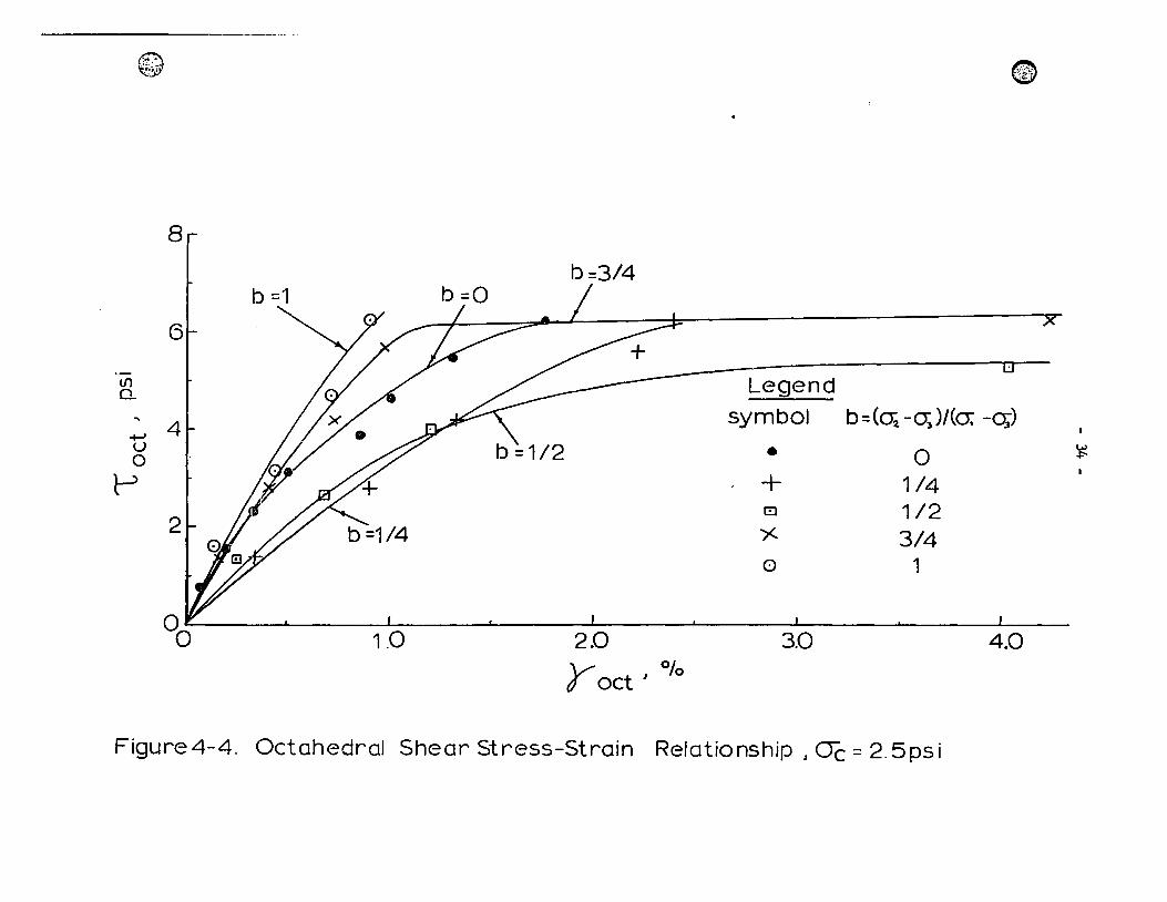
Figure 4.4 Octahedral Shear Stress-Strain Relationship,
<Je = 2.5 psi 34
- vi -
Title
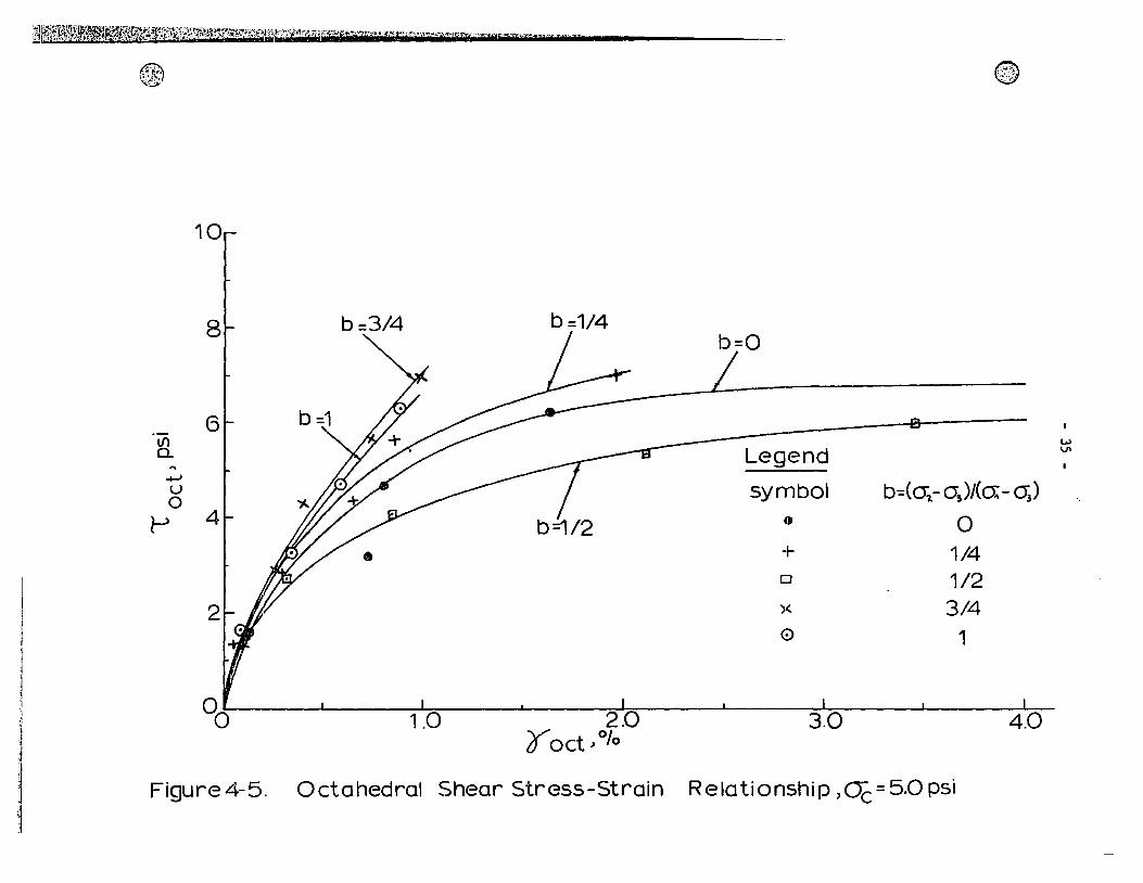
Figure 4.5 Octahedral Shear Stress-Strain Relationship,
Œe =5.0psi 35
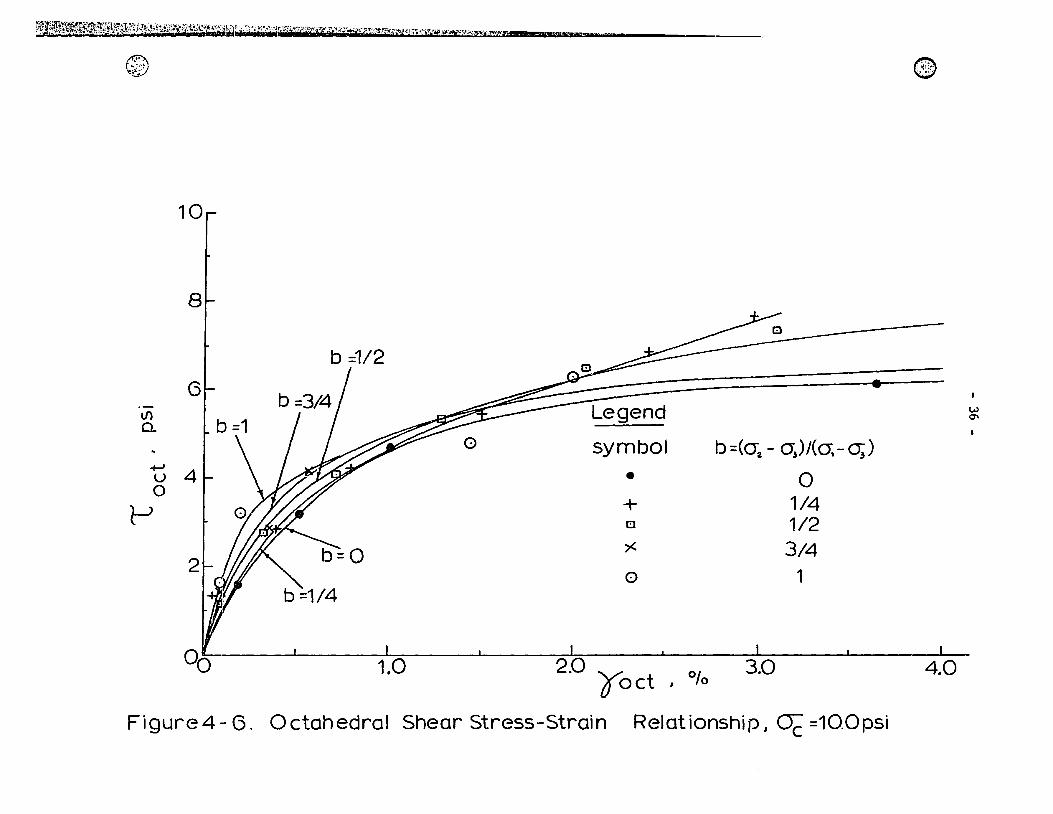
Figure 4.6 Octahedral Shear Stress-Strain Relationship,
cre = 10.0 psi 36
Figure 4.7 Successive Yield Stresses Plotted on Reduced
OGtahedral Planes 37
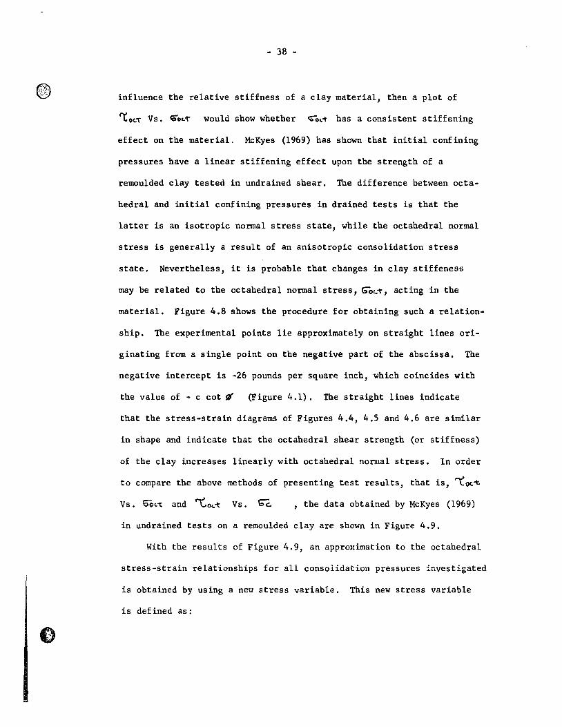
Figure 4.8 Octahedral Shear Stresses at Equa1 Strains vs.
Octahedral Normal Stresses for Drained Tests 39
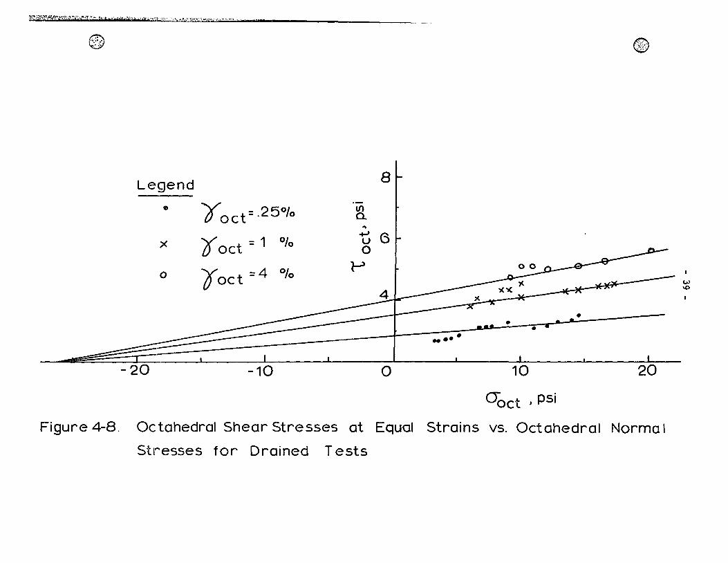
Figure 4.9 Octahedra1 Shear Stresses at Equal Strains vs.
Consolidation Pressures for Undrained Tests
(McKyes, 1969) 40
Figure 4.10 Reduced Stress-Strain Relationship 42
Figure 4.11 e - log P Curve 44
Figure 4.12 Microphotographs of Thin Sections Taken from
Natura1 Clay Samples 45
Figure 4.13 Microphotographs of Thin Sections Taken from
Consolidated Clay Samp1es 46
Figure 4.14 Microphotographs of Thin Sections Taken from
Failed Clay Samples 47
Figure 5.1 Mohr-Cou10mb Plot for the Consolidated Drained
Triaxia1 Tests (Con10n, 1966) 55
Figure 5.2 Failure Stresses and Stress Paths 57
- vii -
Title Page
Figure 5.3 Limiting Circles of von Mises Behaviour
(McKyes, 1969) 58
Figure B-l Geometry of Principal Stress Space 71
Figure B-2 Common Reduced Right Section 74
Figure C-l Clay Structures (Lambe, 1953) 78
Figure C-2 Schematic Picture of Clay Network 79
Figure D-l Interference Co1our Interpretation 82
b
c
c'
e
s
v
(1
(2 (3
(oct O'oct
° Oc
°1 CJ2 Œ3
Œoct Œ~ flJ ~'
_,.i .•
- viii -
NOTATIONS
cohesion intercept with respect to drained conditions
cohesion intercept with respect to effective conditions
void ratio
first stress invariant = 01 + 0"2 +Œ3 pressure
shear strength
volume
increment
strain in the major principal stress direction
strain in the intermediate principal stress direction
strain in the minor principal stress direction
normal octahedral strain
octahedral shearing strain
normal total stress
consolidation pressure
major principal stress
intermediate principal stress
minor principal stress
normal octahedral stress
effective normal stress
angle of internal friction under drained conditions
angle of internal friction with respect to effective
parameters
® ,)::i
(0" """1, ..
\::
"t'oct l:'*
psi
t/m2
t/ft2
TSF
- ix -
shear stress
octahedral shear stress
reduced octahedral shear stress
pounds per square inch
tons per square meter
tons per square foot
tons per square foot
- l -
INTRODUCTION
1.1 ~ General problem
In the study of sail mechanics it is evident that greater atten-
tian must be paid ta the problem of sail behaviour. One of the reasons
for this development is the increasing knowledge of the influence of
physico-chemical factors in governing the response of the sail.
Another reason is the need ta better understand the behaviour of clays
subjected ta external constraints.
When studying clay behaviour, it is necessary ta differentiate
between undisturbed and remoulded soils. Undisturbed clays generally
display greater structural influences than others because of the
arrangement of the sail particles and the nature of the interparticle
forces. Many undisturbed clays can be regarded as possessing strong
interparticle bonds arising from cementing agents, such as carbonates
and oxides, whereas completely remoulded clays lack these bonds and
exhibit different mechanical properties. The magnitude of structural
effects on the strength of an undisturbed clay is reflected in part by
its sensitivity, that is, the ratio of undisturbed ta remoulded
strength.
Leda clay of Eastern Canada has a strong, brittle structure which,
when disturbed, loses virtually aIl rigidity and the clay flows like a
- 2 -
viscous liquide The ability to lose strength on remoulding can be
partly explained by the open, bonded cardhouse structure of the clay,
and partly by its geological history (Crawford, 1963). More detailed
information regarding Leda clay is presented in Appendix C. The
unusual features displayed by the clay, namely, its compressibility
and high sensitivity, concern the engineer since they confront him
with specifie problems of slope stability, settlement predictions and
foundation design.
Slope failures in sensitive Leda clay are often catastrophic and
occur with sudden movemcnts (Eden, 1956; Bilodeau, 1956). Investiga-
tion of these slides has indicated that the clay is usually character-
ized by low friction angles, high cohesion, and low in-situ stresses.
These phenomena have suggested the inadequacy of the classical strength
theories in interpreting the behaviour of sensitive clays. Also, the
stage has not been reached when the shear strength of a soil can be
expressed in terms of physico-chemical properties of the soi1 parti-
cles and the pore fluide The c1assical strength theories of soil
mechanics cannot be used to estimate, with reasonab1e accuracy, the
minimum strength requirements. A1though they have been used, with
sorne success, for remoulded soi1s, the extent to which they can be
applied to undisturbed sensitive clays is in doubt (Crawford, 1963).
1.2 ~ ~ Scope of the Present Study
Recently, a program was begun by severa1 Eastern Canadian
universities to perform a detai1ed ana1ysis of tae response behaviour
& ..... ' ~
- 3 -
of Leda clay. The present study is part of this cooperative investi-
gation undertaken to assess fundamental properties of natural so1ls
and to interpret the soil response in view of the above properties.
The aim of this investigation is to study the behaviour of a
sensitive clay subjected to complex stress states and under low con-
fining pressure conditions. This study includes the influence of the
intermediate principal stress on the yielding of such a material, in
view of the scarcity of conclusive data on the behaviour of undisturbed
natural clays.
Investigation of the behaviour of Leda clay, under conditions
similar to those existing in the field, allows one to obtain rational
strength parameters. For example, in large slope failures, plane
strain conditions often prevail, whereas in small landslides, complex
stress states exist, and the ability to reproduce in-situ conditions
allows one to obtain meaningful results.
The apparat uS used to determine the strength parameters in this
study was designed to reproduce general field conditions, that is, it
provided three principal stresses that could be varied independently
of each other.
In this study, confining pressures ranging from 2.5 to 10 psi are
used. Since these pressures are well below the preconsolidation pres-
sure of the tested soil, it is possible ta study the influence of the
interparticle bonds on the yielding of the ciay and to simulate low
confining pressure conditions of landslide situations. Undisturbed
clay samples were obtained from a site where a slope failure had
- 4 -
occurred, through the cooperation of Dr. P. LaRochelle, Professor of
Civil Engineering, Laval University, Quebec.
The data are presented on principal stress space where a direct
comparison may be made between the experimental results and sorne of
the classical strength theories.
A complementary research program performed in this investigation
involves the study of clay fabric by means of a polarizing microscope
and subsequent interpretation of interference colours obtained.
Undisturbed, consolidated and failed clay specimens are used, and
changes in clay fabric are related to changes in mechanical proper-
ties.
The intent of this study is to increase the present knowledge of
the properties of sensitive clays and provide further insight into
the contribution of natural bonds to the behaviour of sensitive clays.
- 5 -
CHAPTERll
PRESENT ~ OF KNOWLEDGE
Unlike otber materials, tbe strengtb and deformation of cohesive
soils cannot be defined in terms of simple properties such as yield
strengtb and elastic modulus. The nature of tbe clay-water system
renders it difficult to estahlish a unique strengtb criterion. Since
clay soils are not ideal materials and their bebaviour is neitber
elastic nor plastic, it is difficult to apply conventional theories
of mechanics to analyze the sbear strength of a soil.
2.1 Mechanism of Shearing Resistance
In spite of tbe advancement in tbe knowledge of soil physics, it
is impossible to exactly describe tbe mechanisms that resist shear in
an undisturbed clay specimen.
An understanding of the shearing bebaviour of natural clays
requires: ·(a) knowledge of the way in which clay particles interact,
(b) information about the role of water and diffused ions in governing
the nature and distribution of interparticle forces, and (c) knowledge
of possible cementation (or natural) bonds.
A fundamental appreciation of the physico-cbemical properties is
of utmost importance for a better understanding of the deformation and
strength characteristics of clay soils.
®'" ",f.:.:.,' .'
- 6 -
Investigations of this problem by Lambe (1953, 1958) and Rosenquist
(1959, 1962) have clarified the influence of physico-chemical factors
upon the mechanical behaviour of clays. Canadian clays in particular
have been studied by Crawford (1960, 1963), Penner (1963), and Quigley
and Thompson (1966). These authors agree on the fact that the sensi-
tivity of Leda clay de pends upon the brittle, bonded cardhouse struc-
ture of the clay. However, no one has yet subjected this clay to
complex stress states; therefore, it has been impossible to obtain the
complete yield response under varying intermediate principai stress.
The arrangement of clay particles and the interactions among the
solid and liquid phases determine the response behaviour of a clay
soil, that is, the response of the soil to an external set of con-
straints. This geometrical arrangement of mineral particles, called
fabric, together with the associated interparticle forces is generally
defined as the structure of the soil (Yong and Warkentin, 1966). The
concept that clay platelets are surrounded by double water and ion
layers has been accepted by most researchers in the field of soil
mechanics. These adsorbed and partially bound layers primarily serve
to transfer and distribute the electrical forces between the clay
particles, and the nature of the interstitial fluid is of primary
importance to this role.
During shear, interparticle bonds are broken, and particles become
semi-oriented and any force resisting this movement contributes to the
shear strength of remoulded clay (Figure ?l).
The physical mechanisms governing the behaviour of clay soils are:

Structural Bonding \
- 7 -
(0) Undisturbed
Clay Particle
Potential Failure
Plane
Q) c o
~ ~ ~j ----o~-~r__\ --- ~---__ ~CEl~~c=:.? ____ c:::;s. ___ _
o c:::::::::::r "' c ;;) ~ ~ c - c:::::::J ::) ~
Developed Failure
(b) After Sheoring Plane
Figure 2-1. Schematic Clay structures (Yong and WorkentinJ 1966)
- 8 -
1. sliding resistance between particles, and
2. interlocking between particles
However, in a clay-water system, the interaction of clay particles is
such that there is a minimum of actual physical contact between par-
ticles (Yong and Warkentin, 1966). It is believed that the water film
surrounding the clay plate lets yields plastically when the particles
are pushed together with Little or no deformation of the actual par-
ticles. In the light of these concepts, sliding resistance can no ~'
;,1' "
>~
longer be accepted as resulting from particle contact; rather, a more
satisfactory concept of shearing resistance must be developed in such
a way as to take into account the phenomena Just described.
In addition, under low pressures, the shear strength of sensitive
clays is almost totally composed of cohesion. Cohesion may be regarded
as the integral adhesion, because it represents the attraction between
particles in "contact".
The above phenomena govern the response of undisturbed clays. That
is, they determine the yielding and failure behaviour of sensitive
clays subjected to applied external constraints.
2.2 Yielding of Sensitive elays
When investigating yielding and failure of sensitive clays, it is
necessary to differentiate between these two terms. For example, the
failure of brittle mate rials occurs as a fracture with resulting dis-
continuous areas of deformation. Thus "fracture" can be identified
- 9 -
with "failure", while yield is used to describe the onset of irrecover-
able, uniform deformations.
When a'material is subjected to increasing loads, the resulting
stress will eventually become high enough to cause the solid to yield
and, finally, to fail. In most metals, if the state of stress is
uniaxial, it is often easy to specify a unique yield point. However,
if a complex stress field is acting, what combination of .these stresses
will cause yield? It is known, for example, that in most metals a
hydrostatic stress, that is, equal stresses in all directions, will not
cause yie1ding, even for very large values of the confining pressure.
The criteria for deciding which combinat ion of multiaxial stress will
cause yie1ding are called yie1d criteria.
For most metals, a stress-strain re1ationship is characterized by
an initial e1astic stage, followed by irrecoverable plastic deforma-
tions at higher stresses. On1y when there is a sharp "break" in the
stress-strain curve can yie1d be easi1y defined.
On the other hand, cohesive soils are characterized by nonlinear
stress-strain curves. C1ays undergo irrecoverable deformations at
very low stress 1eve1s, and thus their stress-strain re1ationships may
be regarded to represent a succession of yie1d points. Further, in
clay soi1s, where interparticle forces control the soil response, the
stress-strain curves are genera1ly time-dependent. Thus an analytical
description of yie1d or failure of a cohesive soil must take al1 these
factors into account.
Considering the deformation characteristics of sensitive c1ays,
it has been proposed by Go1dstein and Ter-Stepanian (1957) that
~ ~
- 10 -
interparticle forces be divided into two groups, one producing brittle
bonds which permit elastic deformations and then fail, and the other
forming viscous bonds, which break under stress, and reform as the
shearing process continues.
As was previously noted, there are indications that at the con-
tacts between particles of certain c1ays there are strong cemented bonds
(Lambe, 1960; Quig1ey and Thompson, 1966). These bonds act as if they
were britt1e materials, perhaps crysta11ine in nature, and cause sensi-
tive clays to be characterized by high shear strengths at 10w strains.
The maximum shear strength occurs when the bond strength is fully mobi-
1ized and this develops at 10w strains because of the brittle nature of
the cementing agents. Beyond the maximum strength further breakdown of
the cementation bonds occurs with increasing strains. Figure 2.2 illu-
strates the stress-strain response of a sensitive clay and of a
remou1ded or unbonded clay.
A mechanistic understanding of the reasons for the behaviour of a
sensitive clay can be deve10ped by inspection of the nature of the clay-
water interaction. The bonded clay is re1atively stiffer up to point A,
where a structural breakdown occurs and large deformation starts to
develop. As the stress leve1 is increased, partial or total breakdown
of the bonds occur because of the internal complexities of the soil
structure, causing bending, tension, and shear stress. When the soil
structure is subjected to a shear stress, failure of the cementation
bonds is most likely to occur due to the tensile stress resulting
from: (a) bending at the contact points, (b) diagonal tension due to
shear stress, and (c) direct tension due to local dilatations (Conlon,

- 11 -
Sensitive Clay
\ Remoulded Clay
Strain
Figure 2-2. Influence of Structure on Stress-Strain
Relationships
- 12 -
1966). Thus the shear strength of a soi1 structure deve10ped in this
way may not be adequate1y defined by c1assical frictiona1 shear
fai1ure theories.
Remou1ded c1ays, on the other hand, behave different1y. There is
no concentrated breakdown of bonds, rather a progressive breaking
occurs, and these bonds can be identified as the viscous bonds that
break under stress and reform continuous1y as partic1es more relative
to each other.
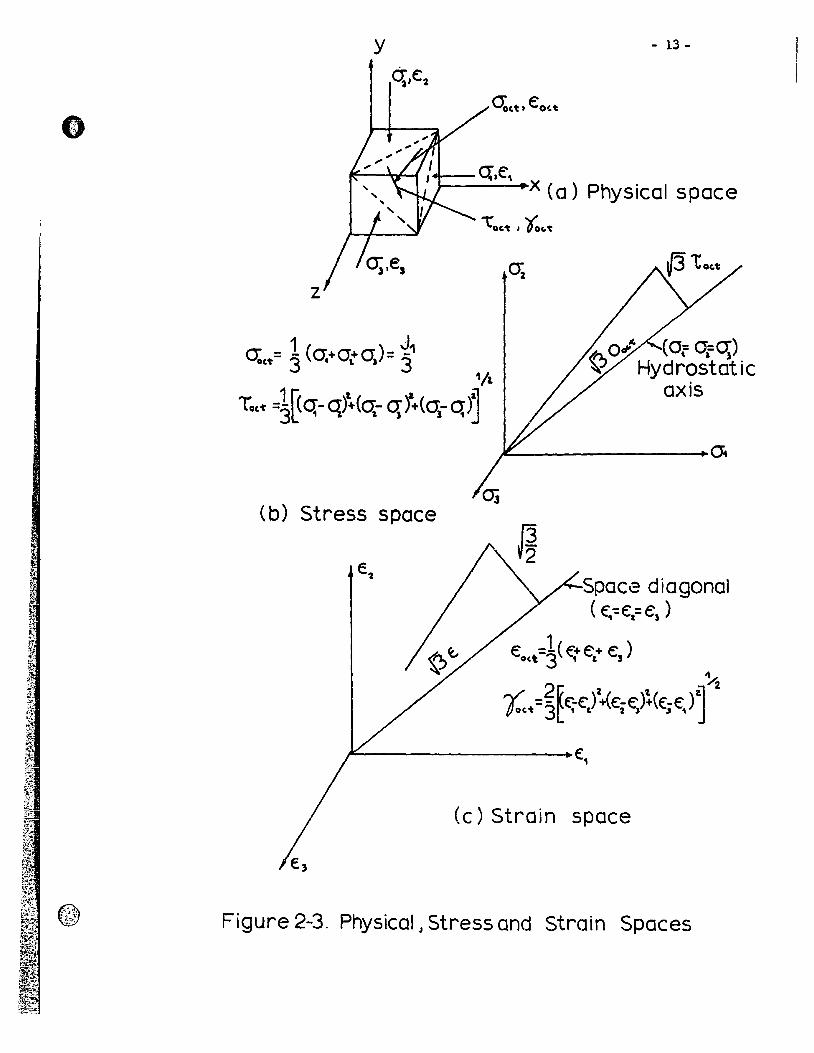
As discussed in Chapter l, it is desirab1e to investigate the
influence of the intermediate principal stress on the yie1d behaviour
of Leda clay. lt was mentioned that the c1earest way of summarizing
the resu1ts was to show yie1d and fai1ure surfaces in principal stress
spaces. To i11ustrate these spaces, schematic diagrams showing the
re1ationships between stresses and strains in physica1 and stress-
strain spaces are shown in Figure 2.3.
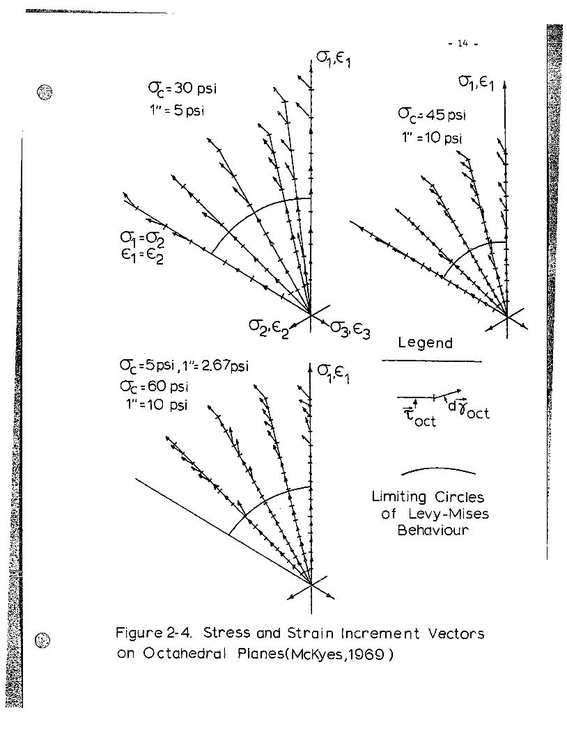
Little is known about tbe behaviour of sensitive c1ays at 10w
stress 1eve1s. McKyes (1969) has shown that, for remou1ded kao1inite,
the von Mises criterion cou1d we11 represent the yie1d behaviour of
the materia1, at 1east up to a certain octahedra1 shearing strain. The
experimenta1 resu1ts obtained by McKyes (1969) are shown in Figure 2.4.
At tbe present time the comp1ex deformation characteristics of
natura1 c1ays subjected to 10w stress 1eve1s are not weIl understood.
In sensitive c1ays interpartic1e bonds may al10w the shear strength
in tension to be equa1 to that in compression, at 1east for 10w
strains and, perhaps, at 10w confining pressures (Con10n, 1966;
Townsend, 1966). lt is weLl known that most sensitive c1ays are
y - 13-
4&---q,e" x (0) Physical space
z
(b) Stress space
Space diagonal ( €'.-=E:1= e, )
€o,t =~ ( ~+ e,+ e, ) ~
t.. =~~e;-E:.l'+k;t;)~(E:;€) J • jIt:-----------..€1
(c) Strain space
Figure 2-3. Physical J Stress and Strain Spaces
@,.{': . ' .•. ' . ..
q-::30 psi
1" = 5 psi
0(=5pSi, 1": 2.67psi
O"c-::60 psi 1" = 10 psi
- 14 -
Q1'€1
cre.:: 45 psi
1" = 10 psi
Legend
+ I~ "t d Ooct oct
~
Limiting Circles of Levy-Mises
Behaviour
Figure 2-4. Stress and Strain Increment Vectors on Octahedrol Planes(McKyes,1969)
- 15 -
relatively stiff and are characterized by brittle behaviour (Crawford,
1963).
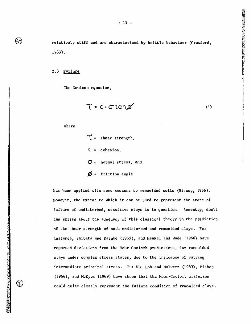
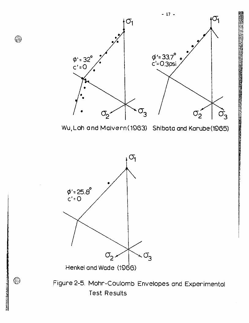
2.3 Failure
The Coulomb equation,
l = c+utan% (1)
where
~= shear strength,
C = cohesion,
(j= normal stress, and
r6= friction angle
has been applied with sorne success to remoulded soils (Bishop, 1966).
However, the extent to which it can be used to represent the state of
failure of undisturbed, sensitive clays is in question. Recently, doubt
has arisen about the adequacy of this classical theory in the prediction
of the shear strength of both undisturbed and remoulded clays. For
instance, Shibata and Karube (1965), and Henkel and Wade (1966) have
reported deviations from the Mohr-Coulomb predictions, for remoulded
clays under complex stress states, due to the influence of varying
intermediate principal stress. But Wu, Loh and Malvern (1963), Bishop
(1966), and McKyes (1969) have shown that the Mohr-Coulomb criterion
could quite closely represent the failure condition of remoulded clays.
- 16 -
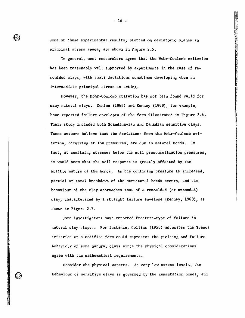
Sorne of these experimental results, plotted on deviatoric planes in
principal stress space, are shown in Figure 2.5.
In general, most researchers agree that the Mohr-Coulornb criterion
has been reasonably well supported by experiments in the case of re-
moulded clays, with small deviations sometirnes developing when an
intermediate principal stress is acting.
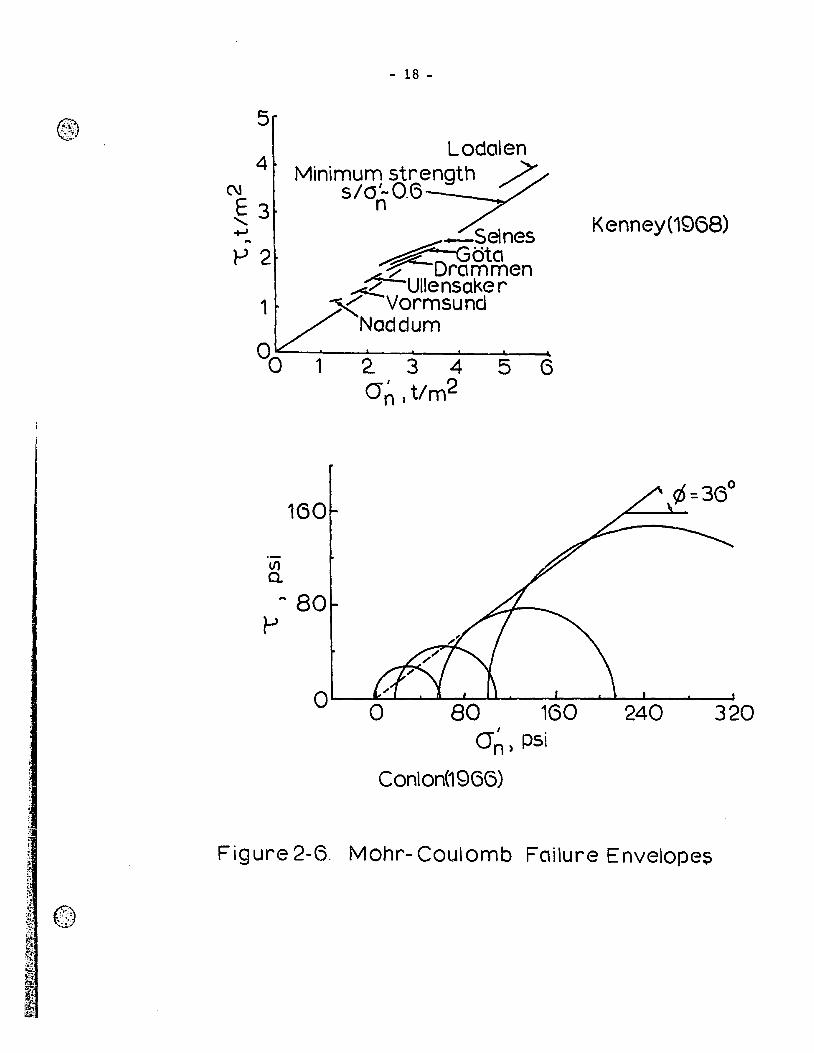
However, the Mohr-Coulomb criterion has not been found valid for
many natural clays. Conlon (1966) and Kenney (1968), for example,
have reported failure envelopes of the forro illustrated in Figure 2.6.
Their study included both Scandinavian and Canadian sensitive clays.
These authors believe that the deviations from the Mohr-Coulomb cri-
terion, occurring at low pressures, are due to natural bonds. In
fact, at confining stresses below the soil preconsolidation pressures,
it would seem that the soil response is greatly affected by the
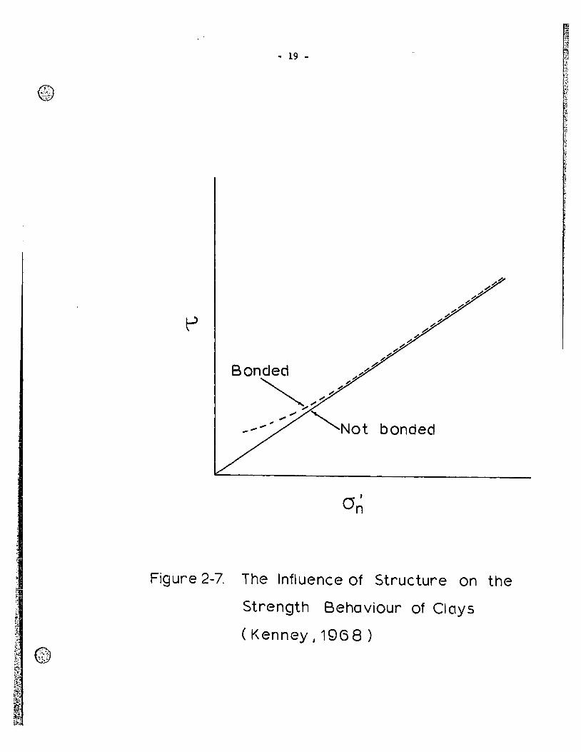
brittle nature of the bonds. As the confining pressure is increased,
partial or total breakdown of the structural bonds occurs, and the
behaviour of the clay approaches that of a remoulded (or unbonded)
clay, characterized by a straight failure envelope (Kenney, 1968), as
shown in Figure 2.7.
Sorne investigators have reported fracture-type of failure in
natural clay slopes. For instance, Collins (1956) advocates the Tresca
1 criterion or a modified forro could represent the yi.elding and failure
behaviour of sorne natural elays sinee the physical considerations
agree with the mathematical requirements.
Consider the physical aspects. At very low stress levels, the
® .. ........ '.
behaviour of sensitive clays is governed by the cementation bonds, and
(/)' = 320 •
c'=o •
- 17 -
r:/J '= 33.70
0
c'=0.3psi
0""3
WU,Loh and Malvern(1963) Shibataand Karube(1965)
1J'=25.BO
c': 0
Henkel and Wade (1966)
Figure 2-5. Mohr-Coulomb Envelopes and Experimental
Test Results
- 18 -
5 LOdalen
4 Minimum strength ~ N 5/0'-0.6 E 3 " -t-J ~
l-'2
1
°0
tI) a.
1
160
~ 80 l-'
n
_Seines ~G"t ~Dra~~en .,;t Ulle nsake r X Vormsund
Naddum
2. 3 4 5 (3 1 2 an) t/m
1 •
an) PSI
Conlon(19GG)
Kenney(19GS)
ç6:: 36°
Figure 2-6. Mohr- Coulomb Failure Envelopes
- 19 -
Figure 2-7. The Influence of Structure on the
Strength Behaviour of Clays
( Kenney ,1968 )
- 20 -
the clay behaves as a brittle material. Also, at confining pressures
below the soil preconsolidation pressure, the frictional resistance of the
clay is very small, and the shearing resistance is almost exclusively com-
posed of cohesion. According to Schmertmann and Hall (1961), the cohesion
component of peak strength in clays develops to its maximum value at very
low compressive strains, while the friction component requires a much
greater strain to reach its maximum value. Since sensitive clays fail at
very low strains, usually of the order of one to two percent, and if the
shear strength reaches a value close to the cohesion value, the clay will
suddenly fail. In addition, as cohesion arises mainly from brittle bonds
in the case of undisturbed Leda clays, the strength of these soils may be
the same both in compression and "extension" tests. However, once the bonds
are broken, the behaviour of these soils may be different and the failure
stresses may or may not correspond to the Mohr-Coulomb requirements.
Knowledge of the strength and deformation characteristics of
undisturbed clays is of utmost importance at low stress and strain
levels because these are the conditions which prevail in field problems
for which limited strains are allowed.
2.4 Questions Arising in ~ Analysis of Leda Clay Behaviour
Leda clay confronts the engineer with specifie, important prob-
lems of soil mechanics. Slope stability analyses, for example, are
among the most difficult problems occurring in this clay. In order
to apply any strength theory, one must first know if a specifie the ory
will provide accurate field predictions, and secondly, if the the ory
- 21 -
is va1id for the most genera1 conditions. Since genera1 stress condi-
tions require three unequa1 principal stresses acting at a point in the
materia1, then one shou1d use an experimenta1 device that wou1d satisfy
genera1 stress conditions, i.e. three principal stresses shou1d be
app1ied to clay specimens.
Then, experimenta1 yie1d and fai1ure surfaces cou1d be represented
in principal stress space and compared to c1assica1 strength theories.
A1so, by investigating the behaviour of Leda clay unàer conditions
of low confining pressures, yie1d and fai1ure surfaces are determined
for this range of pressures, where the influence of the original bonds
has the most effect upon the response of the soi1.
Other important factors that affect the behaviour of Leda clay
are its original structure and its changes in structure due to applied
stresses. A direct observation of the fabric of Leda clay a1lows the
assessment of mechanica1 properties. A1so, fai1ure planes may be
investigated, and the appearance of the fai1ure zone renders it
possible to determine the mode of fai1ure and the distribution of
stresses prior to and during fai1ure. In fact, a clay samp1e with a
single thin straight failure zone is characterized by a re1ative1y
uniform stress state (Yong and Warkentin, 1966).
Further, since the deformations in the three principal strain
directions cou1d be derived, the effect of the various stress combina-
tionson the generation of these strains cou1d be determined and corre-
1ated with the physica1 mechanisms invo1ved in the shear resistance of
Leda clay.
- 22 -
CHAPTER ru
LABORATORY INVESTIGATION
A series of triaxia1 tests invo1ving the application of three
variable principal stresses was performed on a sensitive Leda clay.
The object was to relate the response behaviour of the clay under a
comp1ex stress field to its physica1 characteristics, such as struc-
tura1 bonding and sensitivity. The presence of the intermediate
principal stress al10ws fai1ure and yie1d surfaces to be determined
for complex stress states. In addition, since a11 tests were performed
at 10w confining pressures, the shape of these surfaces cou1d be asso-
ciated with the physico-chemica1 properties of the soi1 in this impor-
tant range of stresses.
3.1 Experimentation
In most soil mechanics prob1ems, rea1istic solutions in terms of
stress and deformation characteristics have been difficu1t if not
impossible to obtain, even when idea1 behaviour was assumed. To improve
solutions, experimenta1 techniques must be deve10ped in such a way as
to obtain realistic prf!dictions of the response properties of the soil
and of the stress distribution within the materia1.
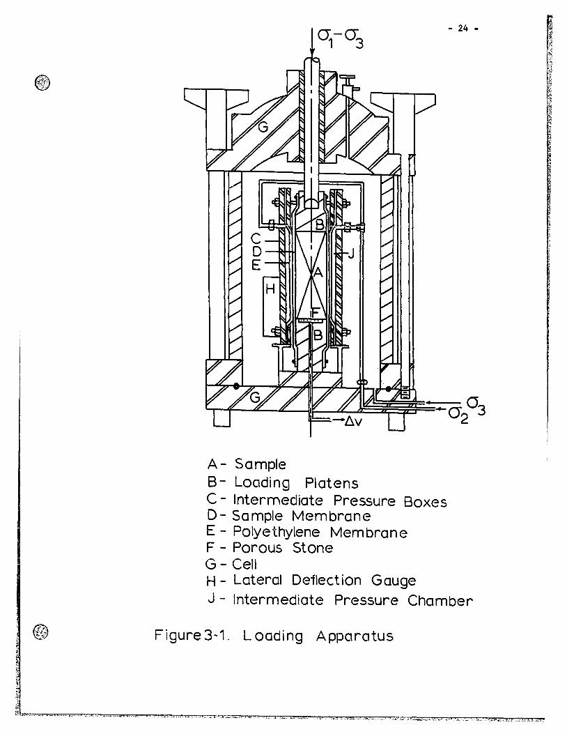
The triaxia1 10ading apparatus used in this study a110wed the
intermediate principal stress to be app1ied to a prismatic clay speci-
men in a manner simi1ar to that of Shibata and Karube (1965). Figure
- 23 -
3.1 presents a detailed view of the characteristics of the triaxial
cell assembly. The device included dial gauges to measure deforma-
tions in the major and minor principal stress directions. This cell
was used by McKyes (1969) to investigate the behaviour of remoulded
kaolinite under states of complex stresses.
The major principal stress was applied by means of a loading
frame, piston and top and bottom lucite caps. The intermediate prin-
cipal stress was applied by a pair of rubber membranes covered by thin
polyethylene sheets and encased in brass boxes. The membranes were
filled up with water and the polyethylene sheets were lubricated to
avoid any friction between the specimen and the membranes. Both the
cell pressure (or minor principal stress) and the intermediate prin-
cipal stress were maintained by self-compensating mercury pressure
systems (Bishop and Henkel, 1962).
It is necessary to mention that aIl tests were performed under
drained conditions, and that volume changes were recorded in order to
derive the strains in the intermediate principal stress direction.
By inspecting the clay samples after failure, it was found that
the sides, on which the intermediate principal stress was acting,
remained plane, indicating a uniform stress distribution throughout
the specimen.
3.2 Material Characteristics
The soil used in this study was a gray Leda clay from a deposit
near Quebec City, Quebec. Soil samples were taken in a recently
;...~
A- Semple B- Loading Platens C - Intermediate Pressure Boxes D- Sample Membrane E - Polyethylene Membrane F - Porous Stone G - Ceii H - Lateral Deflection Gauge
- 24 -
J - Intermediate Pressure Chamber
Figure 3 .. 1. L oading Apparatus
~L_ '""0_- "_0 ...... ....... ... ... . .............. " ..... , ..... • __ ... '''' .'o ... A • . =,."...~'-' ._ ... "'0 ........ lI. .• ~ ........... 0 .00 ..... ..5 ......... __ .. ....... _ ........... C1'3 .,1. ... _ ... 0 •...• .'._ ....... , ... oC _:.', ... j>, •. ~~." ...... c ... o: '.C .. ,> ....... !
- 25 -
failed embankment at a depth of 10 feet, 5 feet below the failure zone.
Undisturbed sampl~s of the clay were obtained through the cooperation
of Dr. P. LaRochelle, Professor of Civil Engineering, Laval University,
Quebec.
Presented in this section are the results of mineralogical and
standard engineering tests performed on this soil.
An X-ray diffraction study of the mineralogical content of this
clay revealed the presence of illite, chlorite and kaolinite, and of
lesser amounts of interstratified mica-like clays and vermiculite.
Non-clay mineraIs identified in the 2-micron fraction included feld-
spar (plagioclase) and quartz, and smaller amounts of amphibole.
The results of standard soil mechanies tests are summarized
below:
Natural water content
Apparent preconsolidation
pressure
Liquid limit
Plastic limit
Specifie gravit y
Gradation (~ finer by weight)
Silt size
- 0.06 mm
Clay size
- 2 micron
- 1 micron
64'f, .:!: 0.5'f,
1.6 TSF
2.80
100'f,
79'f,
60'f,
€;J,":.,:. ,-: .'&
'.
- 26 -
Sensitivity 80
Liquidity index 1.8
This clay is a good example of the type outlined in Chapter l,
which occurs widely across Canada, and confronts the engineer with
specifie problems in the Interpretation of slope stability and in
foundation design.
3.3 Testing Technique
3.3.a Triaxial ~ Programme
From 12 in. x 12 in. x 12 in. undisturbed clay blocks, specimens
measuring 4 in. x 2 in. x 1 1/2 in. were tri~~ed and installed in the
triaxial cell described in Section 3.1.
After installation in the apparatus, each specimen was consoli-
dated at a chosen confining pressure of either 2.5, 5.0 or 10.0 pounds
per square inch. At the end of the consolidation period, small loading
Increments were applied to the sample until failure occurred. The
ratio b ~cri~~-~)was constant for each test, and varied between
zero and one in the study. That is, cr~ varied between cr) and ~ ~
where a;:).. 0; ~ 0; This allowed the complete range of the inter-
mediate principal stress to be covered. Also, when observed on a prin-
cipal stress space, each lcading pa th appeared as a straight line
radiating from the hydrostatic axis.
The applied stresses chosen were such as to determine the yield
and failure envelopes of the soil over the entire l:ange of the inter-
- 27 -
mediate principal stresses. These stress surfaces could then be com-
pared to those obeying ideal behaviours, such as Mohr-Coulomb, von
Mises and Tresca criteria.
l.l.b Optical Studies
In order to investigate the fabric of undisturbed, conso1idated
end feiled cley semples, an optical method for the direct observation
of interference colours from clay thin sections was employed in this
study. This method was applied by Yong and Japp (1968) to study clay
fabric changes in relation to known app1ied pressures and by McKyes
(1969) to investi.gate the shape and thickness of fai1ure zones in
samples of remoulded kao1inite.
This technique, which is detailed in Appendix D, has the advan-
tages that it is possible to distinguish co10urs a litt1e easier than
1ight intensities without the use of a photometer. Lafeber (1968) has
pointed out that the photometrie method cou1d only be app1ied to an
elementary particle configuration, such as parallel orientation.
Thin sections of Leda clay were obtained from samp1es in which the
soil moisture had been exchanged with Carbowax 1000 in the manner des-
cribed by Mitchell (1956), and Yong and Leitch (1967). Microphoto-
graphs of these sections were then taken and interpreted in view of
the interference colour technique, as described in Appendix D.
- 28 -
CHAPTER IV
a EXPERIMENTAL RESULTS
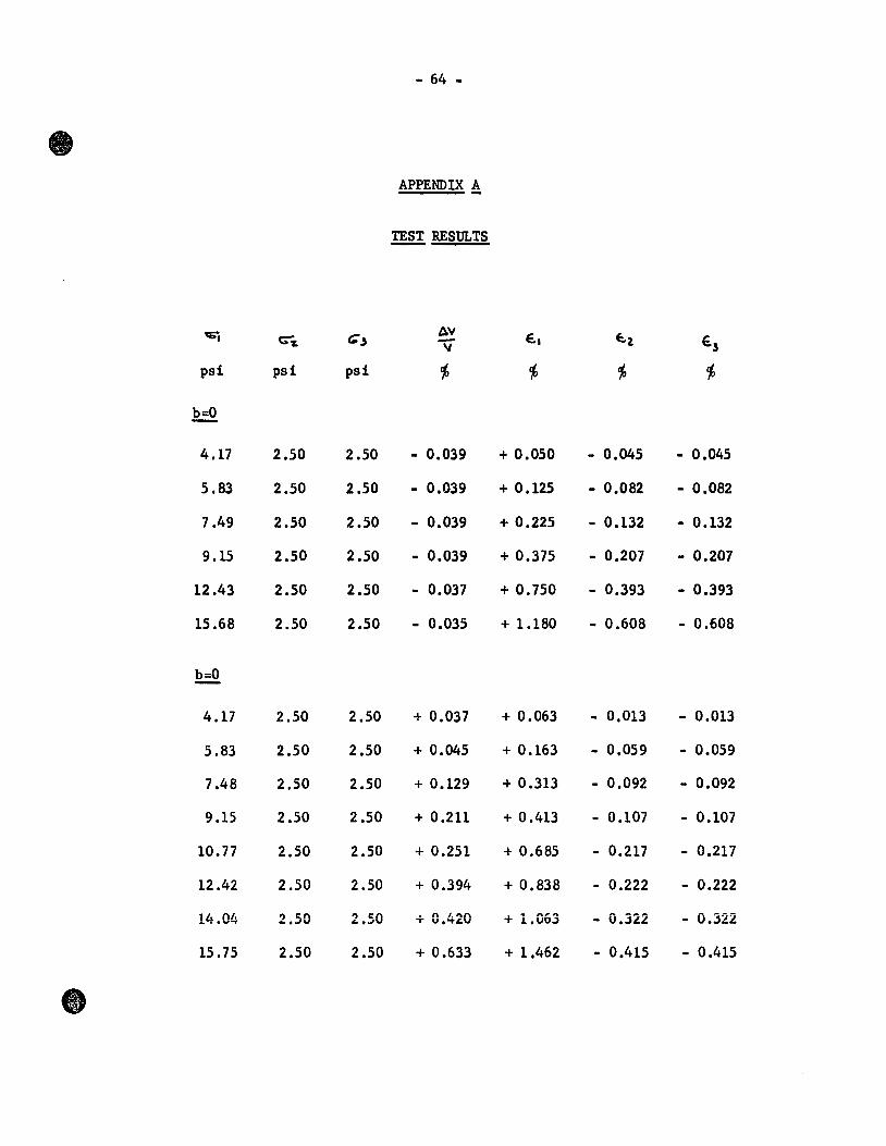
Appendix A presents the test data obtained in this study.
4.1 Failure
The object in this section is to determine whether the Mohr-
Coulomb failure criterion adequately describes the rupture behaviour
of the sensitive bonded clay used in this study.
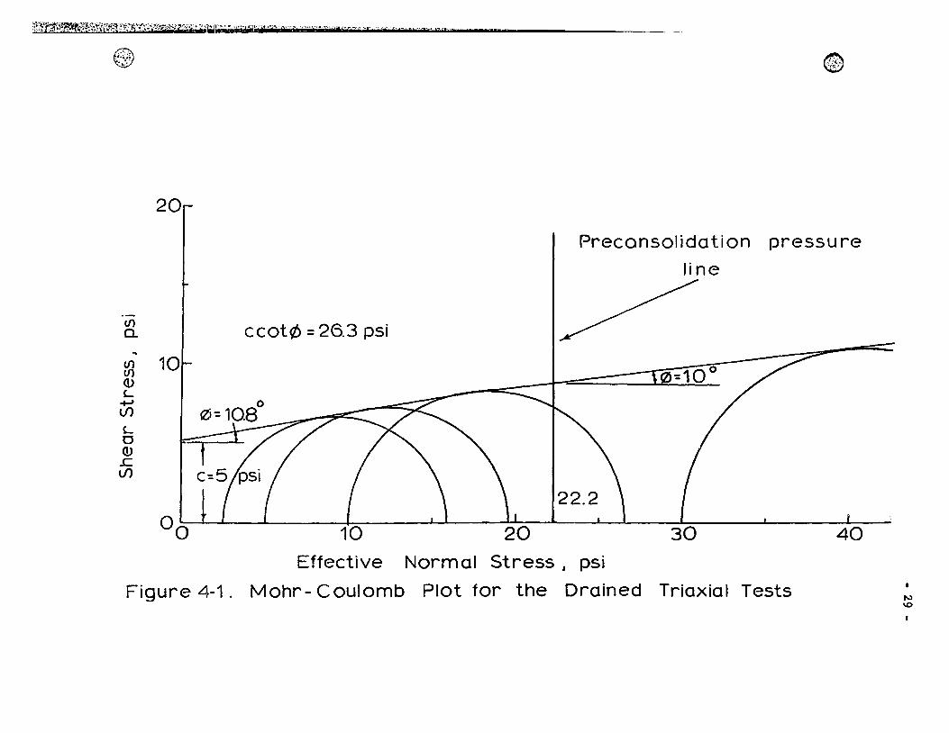
The results of standard triaxial tests performed on prismatic
clay samples are shown in Figure 4.1 on a Mohr diagram. In aIl cases,
including those of varying intermediate principal stress, failure was
characterized by the appearance of distinct slip zones in the samples
and sudden 1055 of bearing capacity. The inclination angle of the
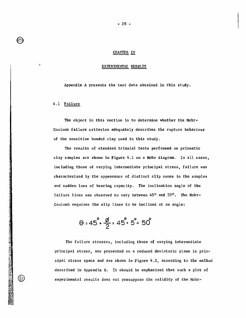
failure lines was observed to vary between 45 0 and 550 • The Mohr-
Coulomb requires the slip lines to be inclined at an angle:
o 0 0 0 0
9 = 45 + "2 ~ 45 + 5 = 50
The failure stresses, including those of varying intermediate
principal stress, are presented on a reduced deviatoric plane in prin-
cipal stress space and are shown in Figure 4.2, according to the method
described in Appendix B. It should be emphasized that such a plot of
experimental results does not presuppose the validity of the Mohr-
~tr~~~~r~~1i\~ti{c~~1!}:~J'\~{;;·~'·}1;:;:~it";"'~~I;;J! '''.' .. ~i·<·t i"k"" , .... ~'.:r ... :o\ " ""~l' •• -., -ia ~~,..~. -. ~~~~~ •. ; .. :U~·_·~"1."'_'''''~' ___ '~''A __ ' __ ~ ___ ._,_.
@)"" .... ,.},,-~ .~.
(/) 0..
(/) (/) (l) L
-+-' lf)
L 0 ID .c lf)
20
10
0 0
ccot(t> = 26.3 psi
20
@',i h
-;-:'~'\.:-~ ~,,":;l'
Preconsolidation pressure
line
-=10 0
40 Effective Normal Stress ~ psi
Figure 4-1. Mohr- Coulomb Plot for the Drained Triaxial Tests N \0
- 30 -
von Mises 01
\
\ \
c=5 psi \ ~ , \
JZf=10.8° , \ \ ~ \ \ , , \ , ,
\ \ , Stress path ,
\ \
0;= °2 ,
\ \ , , '\ ~ ~ \ \ , , \ ,
',,\
Legend symbol Oë
• 2.5psi + 5.0 )( 10.0
Figure 4-2. Failure Stresses Plotted on a
Reduced Octahedral Plane
- 31 -
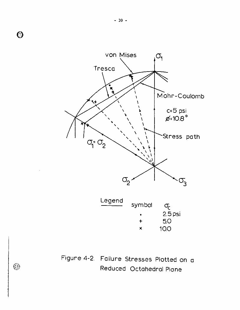
Coulomb criterion for various stress combinat ions but is merely a
convenient metbod for comparing test results witb classical tbeories
(McKyes, 1969).
Figure 4.2 sbows all tbe failure stress combinations on a common
deviatoric plane in principal stress space, togetber witb tbe Mobr-
Coulomb, Tresca, and von Mises failure surfaces. It is clear tbat tbe
Mobr-Coulomb p~edictions based on axially symmetrical strengtb tests
do not comprise a valid failure criterion. The test results sbow
deviations from tbe Mobr-Coulomb criterion similar to tbose obtained
by Sbibata and Karube (1965) for a remoulded clay.
4.2 Stresses ~ Strains
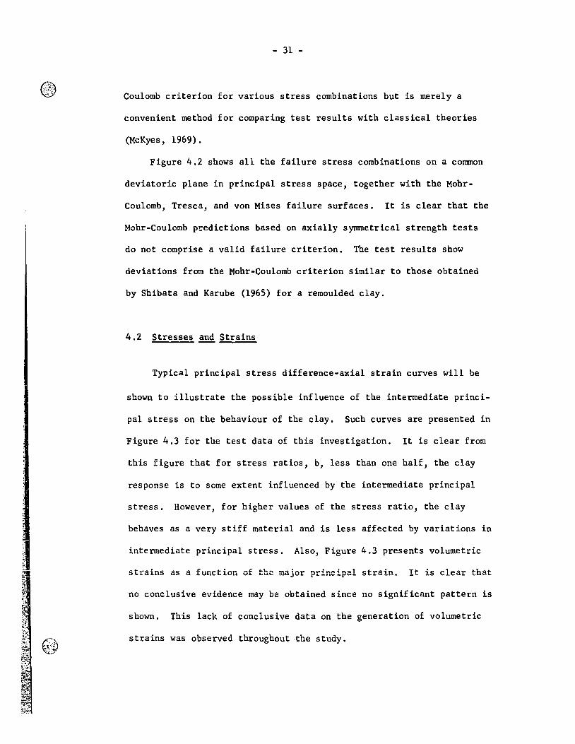
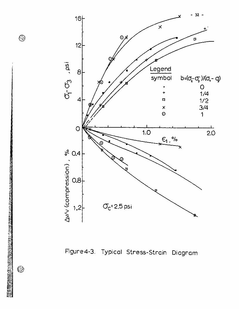
Typical principal stress difference-axial strain curves will be
sbown to illustrate tbe possible influence of tbe intermediate princi-
pal stress on tbe bebaviour of tbe clay. Sucb curves are presented in
Figure 4.3 for the test data of tbis investigation. It is clear from
tbis figure tbat for stress ratios, b, less tban one balf, tbe clay
response is to sorne extent influenced by tbe intermediate principal
stress. However, for higber values of tbe stress ratio, tbe clay
bebaves as a very stiff mate rial and is less affected by variations in
intermediate principal stress. Also, Figure 4.3 presents volumetric
strains as a function of the major principal strain. It is clear tbat
no conclusive evidence may be obtained since no significélnt pattern is
sbown. Tbis lack of conclusive data on tbe generation of volumetric
strains was observed tbrougbout ·tbe study.
16
12
(/) Q.
B ..
~ f
0 4
o
~ 0.4
......... c o CI)
~ 0.8 L Cl.
E o u -
- 32 -
Legend
symbol b=(a-Π)/(0 - q) ~ 3 1
• 0 + 1/4 t:l 1/2 x 3/4 0 1
1.0 2.0
o-c=2.5 psi
Figure4-3. Typical Stress-Strain Diagram
- 33 -
The relationships between octahedral shearing stresses and
strains, for all stress combinations, will be presented because:
(a) yield surfaces are directly derived from these curves, and (b) they
show the influence of the intermediate principal stress upon the yield
loci. These diagrams are shown in Figures 4.4, 4.5 and 4.6. Each dia-
gram shows that there is not a unique relationship for each respective
consolidation pressure; rather, considerable difference betwe~n the
curves occurs, depending on the stress ratio, b. In general, for higher
stress ratios, the clay shows a larger stiffness.
4.3 Yield Surfaces
The purpose of this section ia to de termine whether the yield
behaviour of Leda clay can be easily described by one of the existing
theories, such as the Mohr-Coulomb concept, tbe Tresca condition, or
the von Mises criterion.
Figure 4.7 shows successive yield stress surfaces on a common
reduced octahedral plane in principal str~ss space based on equal
octahedral strains, together with the Mohr-Coulomb, extended von Mises,
and extended Tresca theoretical surfaces, as described in Appendix B.
It is clear from this figure that no classical theory can adequately
describe the behaviour of Leda clay.
4.4 Yielding Analysis
Since it 18 well established that consolidation pressures
® @
8 1
b=3/4
r b, =1 b=O __ L
"'" rY / 6
(/) Legend Q.
-+-' 4 symbol b=(o; -~)/(a: -0;)
u • w 0 0 .p-
l-' + 1/4
2 [!J 1/2 )<. 3/4 0 1
O_Y~~~~~ 1
V- 01 3.0 tJ oct 1 10 4.0
Figure4-4. ()ctahedral Shear Stress-Strain Relationship J OC = 2.5psi
®;.~., ;, .. ;t~
-;;~ ; ,
(/) a. .. ~
u 0
~
10
8 b=3/4 b=1/4 b=O
6 Legend
symbol 4 ft
• -1-
0
)<
0
A '<[9
b=(Œ1.- ~)/(a:. - ~)
0 1/4 1/2 3/4
1
0' , , , , o 1.0 2.0 3.0 4.0
~/ .. oct) 0/0
Figure4-5. Octahedral Shear Stress-Strain Relationship)0(;=5.0psi
w V1
~i~1~~~~~~~~~3~:I~~i~~!· ... ~f;fi~;:;;J1l~~~it'li~tiliJ';~i,~;~~.~~·~~"'~"Jré·-{fflf.'?~Ew)({rr;~,.?; ... :,",tf!j?1;~(·~~i'Ç·\~1F!1~:::ir."'1i-\~~:~H':_\1i.r::~~w='1
~ l~)' ~
li) 0..
+-' u 0
t-Y
10
8
b =1/2 1
G
l b :1 Drfj
2~ ///;/ "-..., - \.;1
B~ ~
Legend
symbol b::(cr~ - ~)/(a,-o;)
• 0 + 1/4 t:l 1/2 )( 3/4 0 1
~.'.> ~
00 1.0 2.0 y; 01 3.0 4.0 o oct, 0
Figure 4 - G. Octahedral Shear Stress-Strain Relationship J CYc" =10.0psi
w 0-
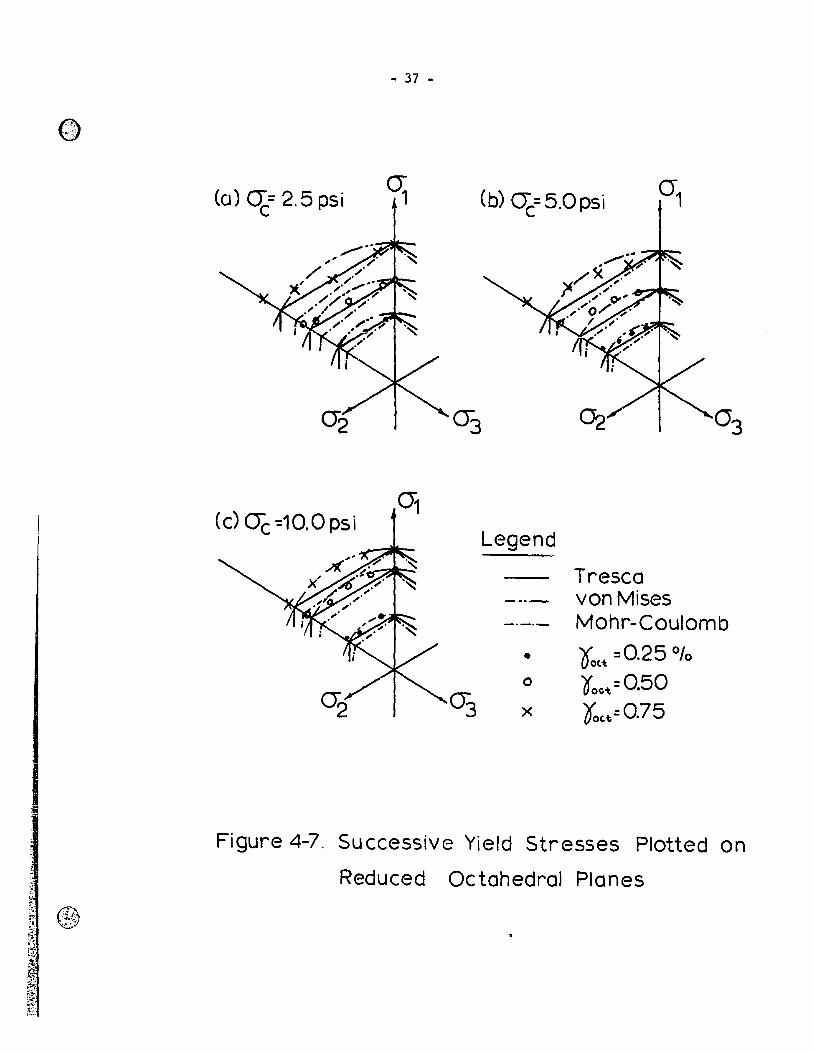
- 37 -
(0) q= 2.5 psi (b) Œc=5.0pSi
(c) Oè -=10.0 psi Legend
-Tresca
-.-- von Mises ----- Mohr-Coulomb
• 0: =0.25 010 ott 0 ooç-t=O.50
03 x Oc,tt=O.75
Figure 4-7. Successive Yield Stresses Plotted on
Reduced Octahedral Planes
- 38 -
influence the relative stiffness of a clay material, then a plot of
'1: 0"1" Vs. 6'01.1" would show whether ~oc.'t has a consistent stiffening
effect on the material. McKyes (1969) has shown that initial confining
pressures have a linear stiffening effect upon the strength of a
remoulded clay tested in undrained shear. The difference between octa
hedral and initial confining pressures in drained tests is that the
latter is an isotropic normal stress state, while the octahedral normal
stress is generally a result of an anisotropic consolidation stress
state. Nevertheless, it is probable that changes in clay stiffeness
may be related to the octahedral normal stress, ~O~~, acting in the
material. Figure 4.8 shows the procedure for obtaining such a relation
ship. The experimental points lie approximately on straight lines ori
ginating from a single point on the negative part of the abscissa. The
negative intercept is -26 pounds per squarp. inch, which coincides with
the value of - c cot tif (Figure 4.1). The straight Hnes indicate
that the stress-strain diagrams of Figures 4.4, 4.5 and 4.6 are similar
in shape and indicate that the octahedral shear strength (or stiffness)
of the clay increases linearly with octahedral normal stress. In order
to compare the above methods of presenting test results, that is, ~O'~
Vs. 601."'(; and "l.oc.-t Vs. bG ,the data obtained by McKyes (1969)
in undrained tests on a remoulded clay are shown in Figure 4.9.
With the results of Figure 4.9, an apprmcimation to the octahedral
stress-strain relationships for a11 consolidation pressures investigated
is obtained by using a new stress variable. This new stress variable
is defined as:
~l'",~~p.x~t:'!;r~~~l'::'·i1h"'.;r ,'!'-......... '.' -, ,.. '{ "':~~:.lt:_~L...:.:_,: .... ::>::~~.")·1m .... _t:.~."'"'7~~",-'_~·<~~"':.l.''''' ......... _ .... _____ _
e·· -t .. l'.s· •• <
Le~;Jend
• Yoct=·25%
x 0' oct = 1 %
0 ooct =4 0/0
-10
8
tIl a. .. "06 0
P
o
~)(
• • _ ... 10
Œoct J psi
_. ~ )( )f~
•
.tm\ ~
20
Figure 4-8. Octahedral Shear Stresses at Equal Strains vs. Octahedral Norma 1
Str'esses for Drained Tests
c...> \0
,~i1-t·-f:i~W{t;:f~!4;~~Î:~;~'!.t:~,~~·::~"..r)t~';O;·\f:'··~'·Y:"'1~ç:'<"." ·~"·If'·;'O<'~)';t5' .. · ... • " ... ,,' f ~." ••• ~ ... :, "," " ~.''" ......
t.?\ t~ @
40
30 -(oct ft~ psi
20r ~._. ~ ~ ooct ... _n. 0
1 10
1 1 O~~ n-0.1 010 -~
0 0 ~
0 -20 -10 0 10 20 30 40 50 GO
OC., psi
Figure 4-9. Octahedral Shear Stresses at Equal Strains vs. Consolidation
Pressures for Undrained Tests (McKyes J 1969)
- 41 -
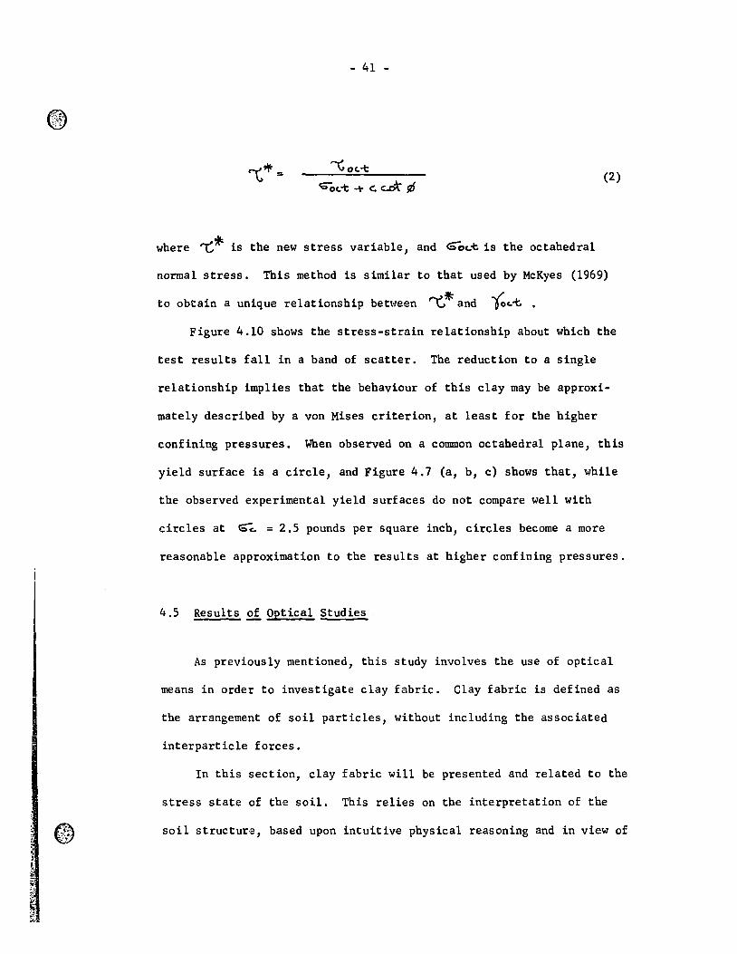
(2)
where '"'G~ is the new stress variable, and 6ôc..~ is the octahedral
normal stress. This method is similar to that used by McKyes (1969)
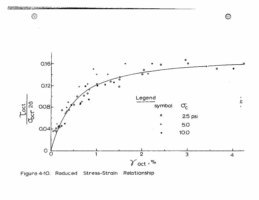
to obtain a unique relationship bet\-1een r-t.,.:J#: and lo,--t:'. . Figure 4.10 shows the stress-strain relationship about which the
test results fall in a band of scatter. The reduction to a single
relationship implies that the behaviour of this clay may be approxi-
mately described by a von Mises criterion, at least for the higher
confining pressures. When observed on a common octahedral plane, this
yield surface is a circle, and Figure 4.7 (a, b, c) shows that, while
the observed experimental yield surfaces do not compare well with
circles at ~, = 2.5 pounds per square inch, circles become a more
reasonable approximation to the results at higher confining pressures.
4.5 Results of Optical Studies
As previously mentioned, this study involves the use of optical
means in order to investigate clay fabric. Clay fabric is defined as
the arrangement of soil particles, without including the associated
interparticle forces.
In this section, clay fabric will be presented and related to the
stress state of the soil. This relies on the interpretation of the
soil structure, based upon intuitive physical reasoning and in view of
Ff~~?'1j~;f!t~i~$a~~;st~~·p:;~'~'~>~\~~it~::t';~'."':"(7i~lI'·'·'. "tl*lb; '., ",. l' ' " « "3" "7- -
eD'··· t..- ;!' ~:.-,\.,
o + • o o
+ o + + _______ 0 +
~g
"0 ~ 0,08 o ~ ~ u
00
~ . o
Legend
symbol
o
+
oc 2.5 psi
5.0
• 10.0
©
o •
, , 00- 1 2 3 4
Yoct ) 0/0
Figure 4-10. Reduced Stress-Strain Relationship
.poN
ft
- 43 -
previous studies on the structure of Leda clay.
The microscopie views which are of interest are those regarding
sections of undisturbed, consolidated, and failed clay samples. The
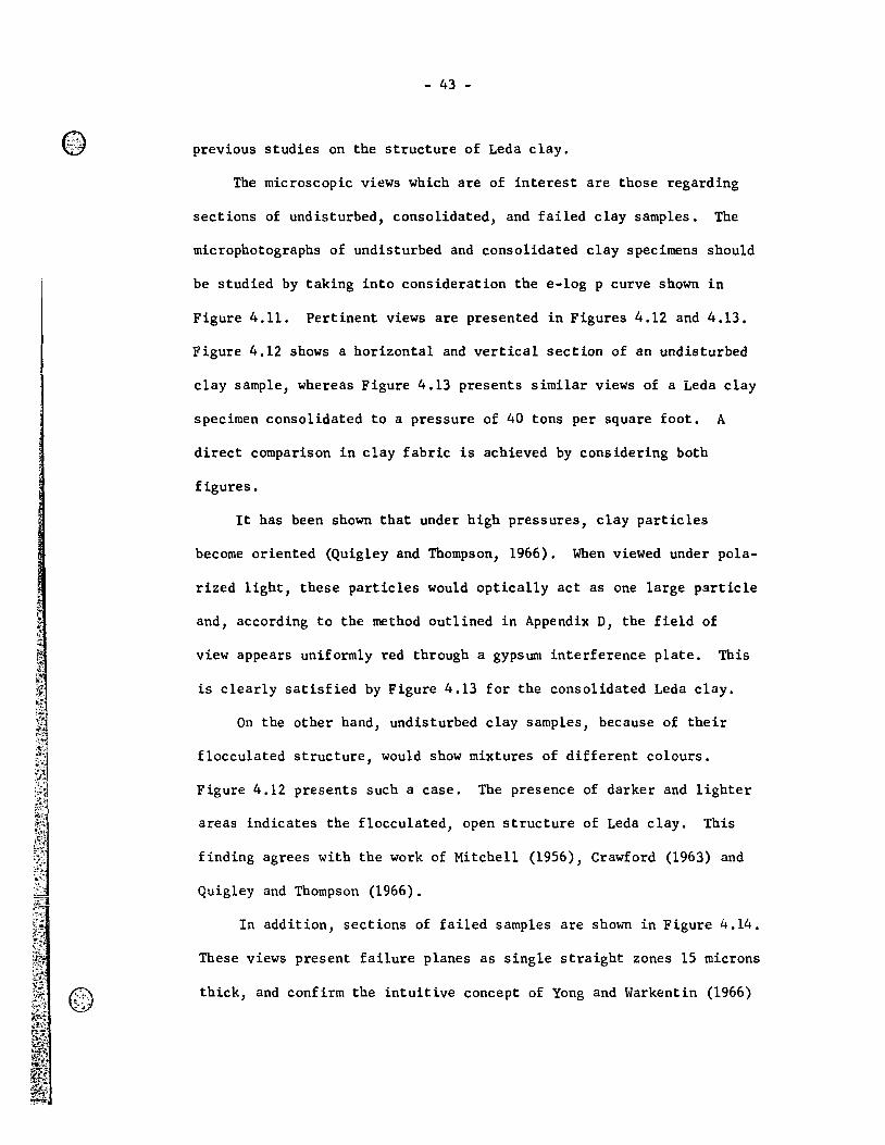
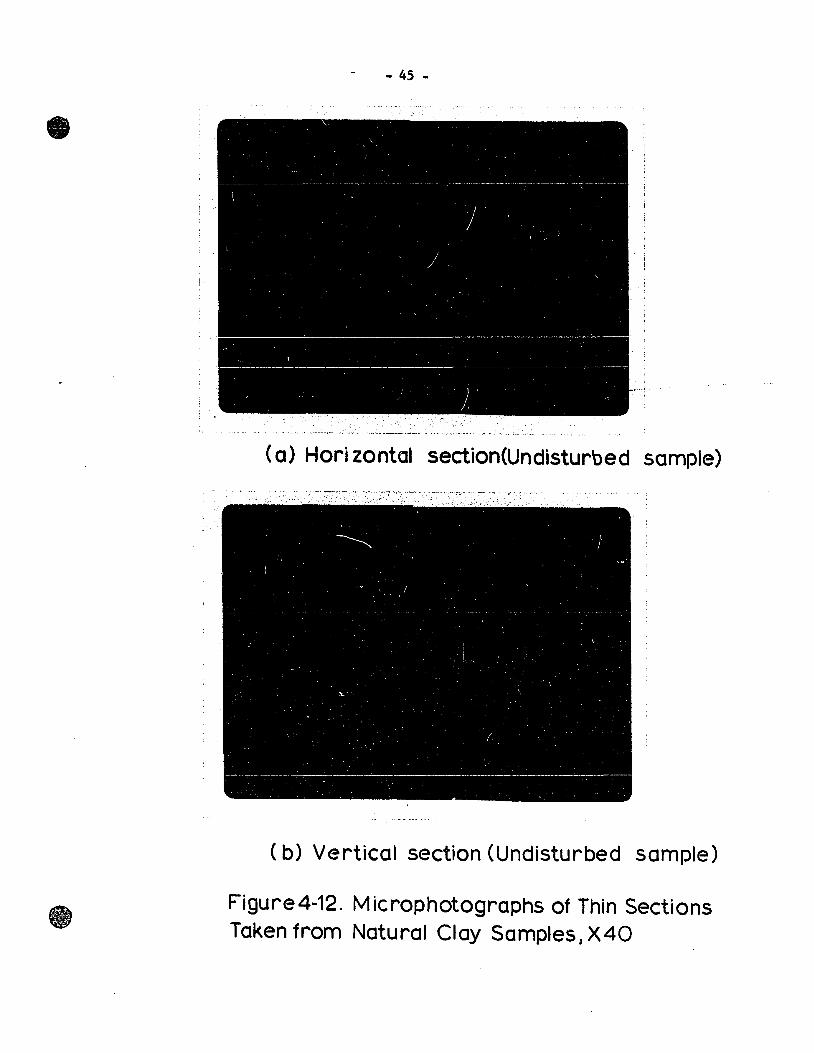
microphotographs of undisturbed and consolidated clay specimens should
be studied by taking into consideration the e-log p curve shown in
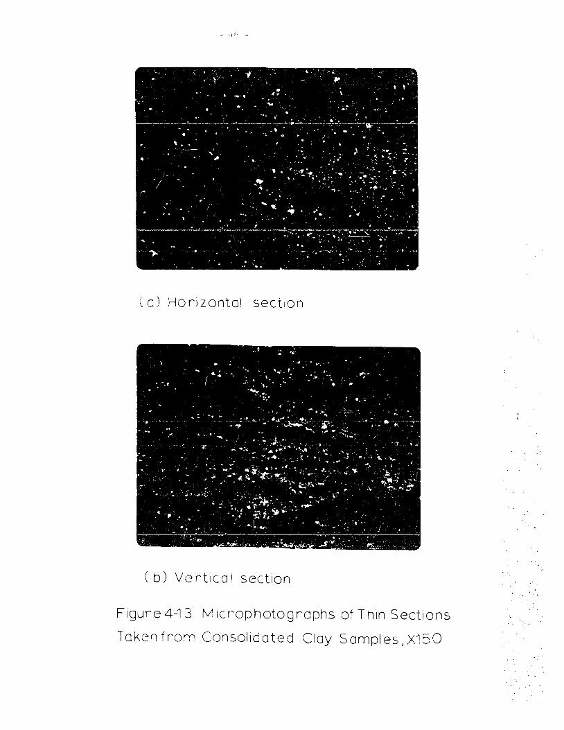
Figure 4.11. Pertinent views are presented in Figures 4.12 and 4.13.
Figure 4.12 shows a horizontal and vertical section of an undisturbed
clay sample, whereas Figure 4.13 presents similar views of a Leda clay
specimen consolidated to a pressure of 40 tons per square foot. A
direct comparison in clay fabric is achieved by considering both
figures.
lt has been shown that under high pressures, clay particles
become oriented (Quigley and Thompson, 1966). When viewed under pola-
rized light, these particles would optically act as one large particle
and, according to the method outlined in Appendix D, the field of
view appears uniformly red through a gypsurn interference plate. This
is clearly satisfied by Figure 4.13 for the consolidated Leda clay.
On the other hand, undisturbed clay samples, because of their
flocculated structure, would show mixtures of different colours.
Figure 4.12 presents such a case. The presence of darker and lighter
areas indicates the flocculated, open structure of Leda clay. This
finding agrees with the work of Mitchell (1956), Crawford (1963) and
Quig1ey and Thompson (1966).
In addition, sections of failed samples are shown in Figure 4.14.
These views present failure planes as single straight zones 15 microns
thick, and confirm the intuitive concept of Yong and Warkentin (1966)
i
1
l i
1 1 l ,
@, ... ~~ :.-: .,-.'
1.8
1.6 ....
1.4 r-
1.2 r-(!)
0 -t-J ----=
-0 rY 1.0
-0
0 >
0.8 r-
~ 0.6 .61
---:---r--
1-
1\ 1 -
r-t-~- - t---t---- r--r-- ~ ---- r----
--
:1 2 p) t/ft 1
\ ~ ~
1\ ~
i-- .............
r--- r-..... ....... 1\
'\.
'" -~
10
~ 1\
~ ~
100
~ ~
Figure 4-11_ e-logP Curve
~-~ .. _~~~_-_IL~ .. _ .«-"'.·,.o.:t<Ilu.i''''-.... a:x;&; ... 4~~'.j,<Q.a~~~~x~ll.$;i~?i'Jf..~:1<~1'<~t~~-1ii~~:(t.~7!~j~Dnl
- 45 -
.-1 • •
-------~-----------~------~-------------------------
- . . I! -. ,
. - . ., .. _~ .. ~ ......... ---.-.. _'.-"'_ ..... _.~-----_.-_ ... -._~ .. _~_." .....• ' ~~-_ .. ,.~ ~ ..... "-, .. ~_. ,
(a) Hari zontal section(Undisturbed sample)
(b) Vertical section (Undisturbed sample)
Figure4-12. Microphotographs of Thin Sections Taken from Natural Clay Samples
J X40
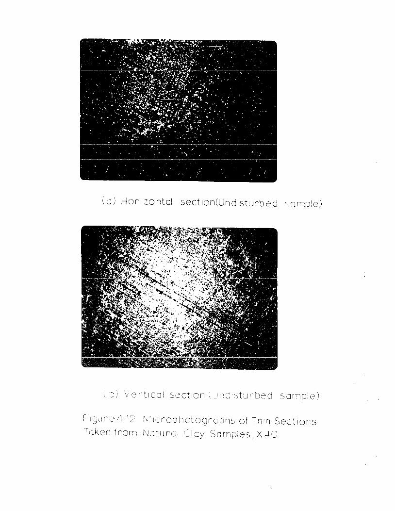
F 1 (j Ll r~ e 4 - Î 2 i\1ll r~ 0 p hot 0 g r 0 ::J h S of T n 1 n Sec t 1 ons
foken from NJturol (::Joy Somples) X~+O
- ,," -
(a) Horizontal section
( b) Vertical section
Figure4-13 Mlcr~ophotogrcphs of Thin Sections
Taken from Consolidated Clay Samples, X.150
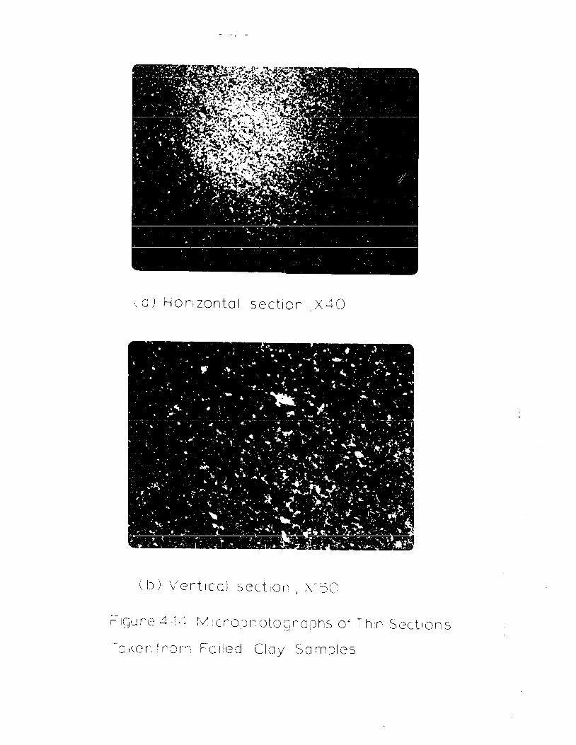
\0) HOrizontal section X":+O
(i)) Vertical sectlOrl J Xl50
FI~ure 4-1·4 f\! icrO:Jnotogrophs of Thin Sections
T 0 f\ c n t r 0 ni F 0 Il e dei a y Som pie s
- 48 -
that, under uniform stress field conditions, the failure zone of a
cohesive soil sample can be of the type illustrated in Figure 4.14.
- 49 -
DISCUSSION ~ RESULTS
As stated in Chapter II, the analysis of soil response must
involve a study of the physical properties of the clay-water system.
Thus this chapter will relate observed behaviour to physical mechanisms
that govern the clay response.
5.1 ~ Behaviour
The strength of cohesive soils may be described by using analy
tical concepts whenever possible and by considering the physical
mechanisms that determine the soil response behaviour.
•
When the application of the Mohr-Coulomb theory is in doubt, th1s
is unfortunate because it is very desirable for practical purposes to
have a satisfactory the ory for the determination of strength parameters
from standard triaxial tests.
It is shown on a reduced deviatoric plane in Figure 4.7 that at
10w equivalent strains, the reduced yie1d surfaces in principal stress
space are close to regu1ar hexagons. Such yield loci define a mate
rial in which shear strains are a unique function of the maximum shear
stress and overal1 confining pressure, and it is known as the extended
Tresca criterion. From the soi1 response the indication is that the
shear resistance of Leda clay is of a pure shear type, rather than
frictions1. In other words, at stresses below the preconsolidation
e - 50 -
pressure in this undisturbed clay, the influence of the intrinsic
stresses controls the shearing resistance. Under these pressures, the
soil response behaviour is governed by the brittle nature of the inter
particle bonds. Failure occurs at low strains (Figures 4.4, 4.5 and
4.6), and the consolidation pressure has only a small effect upon the
strength of Leda clay (Figure 4.1). At very high confining pressures,
structural brea~~own cccurs because of the stresses applied to the
clay and failure of the brittle interparticle bonds follows the genera
tion of shear stresses and tensile stresses acting on the individual
clay particles (Con Ion, 1966).
Evidence of the natural bonds upon the yield characteristics of
Leda clay has been achieved because, as shown in Figure 4.7, approxi
mate model relationships between the equivalent shear stresses and
strains were obtained at different consolidation pressures. These
findings imply the validity of the extended Tresca at lower confining
pressures and of the von Mises criterion at higher octahedral normal
stresses. It was shown in Chapter IV, Figures 4.7 and 4.10, that
circles in stress space become a better approximation to the yield
behaviour of Leda clay at higher confining pressures. This is so
because, under these high stresses, breakdown of the clay bonded
structure occurs and the clay behaves more as a remoulded soil. This
fact agrees with the findings of Conlon (1966) and Kenney (1967, 1968).
Also, McKyes (1969) has shown that the behaviour of remoulded kaolinite
is weIl represented by the von Mises criterion in the initial portion
of the stress-strain curve. In this investigation, considerable experi
mental scatter is present (Figure 4.10), and further study has to be
- 51 -
carried out in both the physico-chemica1 aspect and the yie1d behaviour
of Leda clay.
From the experimenta1 resu1ts it is c1ear that the concepts of
shearing resistance assumed at the yie1d and fai1ure conditions, by the
Mohr-Cou10mb criterion, cannot be app1ied.
When the behaviour of the clay response ls analyzed at 10w strains,
1t 18 apparent that the physical mechanisrn5 that govern the shear
resistance are very different from those acting after large straining
occurs. In fact, when fai1ure is reached, macroscopica11y observable
shearing planes develop, and the clay partic1es in the slip zone have
a1igned themse1ves para11e1 to the fai1ure plane (Figure 4.14). That
is, preferred partic1e orientation occurs, and when investigating the
deformation characteristics at 10w and high strain 1eve1s, account must
be taken of the changes in soi1 structure as a resu1t of the shearing
process.
In genera1, it is c1ear that this clay behaves as a stiffer mate
rial under the influence of higher intermediate principal stress ratios.
At the present time, it is not known whether the increase in stiffness
is due to (a) a corresponding increase in the octahedra1 normal stress,
(b) the soi1 response behaviour under the various stress ratios, or
(c) a combination of (a) and (b). A1so, it is be1ieved that the undis
turbed clay structure and in particu1ar the brittle bonds are a major
factor in governing the response of Leda clay, according to the state
of stresses existing in the material.
- 52 -
5.2 Failure
In aIl samples tested, failure was observed to occur by means of
two symmetrical shearing planes. However, the angle of inclination of
the sli~ lines was not constant, but it varied with the intermediate
principal stress difference. No failure was observed to have occurred
by uniform yielding (or bulg1ng); th1s fact may have resulted from the
experimental constraints, that is, top and bottom loading caps.
Figure 4.2 presents the failure stresses on a common deviatoric
plane. It is evident that, when an intermediate principal stress acts,
deviations from the Mohr-Coulomb predictions are obtained. stnce the
amounts of shear and volumetrie strains in the mate rial differ when
the intermediate principal stress is or is not present, the indication
1s that fabric changes from the undisturbed state must be distinct in
the two conditions. As Figure 4.3 shows, the strain at failure i5
much less, when the intermediate principal stress acts, than that of
the axially symmetrical case of ~~ = ~3 • That is, tbe elay struc
ture reacts differently to the various stress combinations. This
could account for the increased strength and deviations from the Mohr
Coulomb criterion in the intermediate stress range.
The question about the application of the Mohr-Coulomb eriterion
in the case of Leda clay or sensitive clays in general was brought up
in Chapter Il, in view of the complexities of the undisturbed clay
water system. This study has shown that the Mohr-Coulomb failure
criterion does not accurately describe the behaviour of Leda clay in
this important range of stresses.
- 53 -
A1so, this investigation has shown that the octahedra1 shear
strength of Leda clay in drained tests varies 1inear1y with the octa
hedra1 normal stress, plus a constant equal to " ecot si ". Similar
evidence has been shown from uniaxia1 tests (Henke1, 1968) and for
remou1ded kao1inite under comp1ex stress states (McKyes, 1969).
Another problem mentioned previously was that of determining
whether a uniform stress field was acting on the clay samp1es in this
study. Yong and Warkentin (1966) suggest that under uniform stress
conditions, failure zones are characterized by single rupture planes.
In this study, the direct observation of the Interference colours
was chosen as the most usefu1 method of giving meaningful soil fabric
characteristics. Appendix D exp1ains in detail the Interpretation of
the interference co10urs obtained in this study.
Evidence of thin fai1ure zones is shown in Figure 4.14. The
fai1ure planes observed in this study are seen to be single, straight
thin fai1ure zones of very high degree of partic1e para1le1ism, as
indicated by the soUd blue line in Figure 4 .. 14. The thickness of the
fai1ure zone is seen to be approximate1y fifteen microns. Further, the
clay structure in the surroundings of the fai1ure plane is apparently
similar to that of undisturbed clay (Figure 4.12). The presence of
single failur~ planes supports the assumption that the stresses were
re1ative1y uniform over the entire clay specimen.
5.3 Comparison ~ Analysis of Related Work
Recent studies on the yield and fai1ure behaviour of undisturbed,
- 54 -
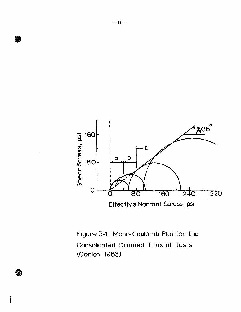
sensitive c1ays have shown interesting resu1ts. Bonded natura1 c1ays,
when subjected to standard triaxia1 tests, exhibit the fai1ure behaviour
presented in Figure 5.1 (Con10n, 1966). Simi1ar fai1ure enve10pes have
been reported by Kenney (1967, 1968) and a1so are shown in this study
(Figure 4.1). The re1ationship shown in Figure 5.1 presents three
distinct behaviours.
Section (a) represents the case of undisturbed specimens sheared
under extreme1y 10w confining pressures. The behaviour of the clay
is governed by the nature of the cementing bonds and by the stresses
experienced by the pore water. The failure plane is usual1y vertical,
indicating a sp1itting or tension fai1ure.
Section (b) shows the case of samp1es sheared under 10w consolida
tion pressures. The slope of the failure envelope is close to the
horizontal, indicating that confining pressures have litt1e effect
upon the shear strength of the materia1. That is, under such all
around pressures, the undisturbed clay structure is preserved, and the
fai1ure stresses will be determined by the relative strength of the
interparticle bonds, in particu1ar, the cementation bonds. Therefore,
it is c1ear that, in the case of a strong1y bonded clay, a very 10w
friction angle is obtained, so long as the confining pressures are
be10w the preconso1idation pressure of the undisturbed soi1. The tests
in this study were performed under the ab ove conditions, and the results
are shawn in Figure 4.1. ln this case, a value of ~ = 10.80 was
obtained; this, in fact, is a 10w friction angle.
Section (c) represents the case of specimens sheared under high
confining pressures. From this it is noted that there is essential1y
1 1 1 1 1 1 1
- 55 -
'a b
Effective Norm al Stress" psi
Figure 5-1. Mohr- Coulom b Plot for the
Consolidated Drained Triaxi al Tests
(Conlon 1 1966)
- 56 -
no cohesion intercept and therefore, when sheared, this soi1 behaves
essentia11y as a norma11y conso1idated and unbonded clay and is able
to fu11y mobi1ize its friction angle. Thus, at sufficient1y high a11-
around pressures, even without the application of a stress difference,
the original bonds break down because of the overa11 volume change and
the interna1 comp1exities of the soi1-water system, causing bending,
tension and shear stresses.
Based on experimental eviàence, several modiÏications to the
classical failure criteria have been suggested. Shibata and Karube
(1965), working with remou1ded c1ays, suggest a slight1y rounded shape
for the failure surface in principal stress space, fo110wing c10sely
the out1ine of the Mohr-Coulomb criterion (Figure 5.2).
Composite stresses in a clay sample May be established by using
hollow cylindrical specimens which would allow for pressures to be
app1ied both internally and externa1ly, in addition to axial stresses.
The resu1ting stresses May be computed by using thick-walled tube
theory. Simi1ar experiments were reported by Wu, Loh and Malvern (1963),
and the test results are shown in Figure 5.2
McKyes (1969) reports failure stresses obeying Mohr-Coulomb predic
tions in the range of intermediate principal stress. The experiments
were performed on remoulded samples of kaolinite. These results are
shown in Figure 5.2
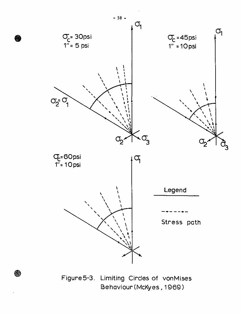
In addition, McKyes (1969) was able to represent the initial yie1d
behaviour of remou1ded kao1inite by means of p1asticity concepts
derived for the von Mises requirements. The resu1ts are shown in
Figure 5.3 and May be direct1y compareà with those obtained in this
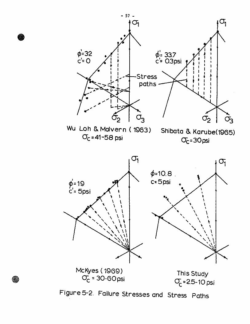
, cp=32 c'= 0
- 57 -
01
~'= 33.7 c'= 0.3 psi
Stress paths
1 f J f 1
Wu Loh & Malvern ( 1963) O"c=41-58 psi
1
P,= 19 c'= 5psi ,
\ \ \ \
\ \ \
~ " \ \ " " \ \ \ " , ,\,
" ", \' \ '" , \ \ '" \ \ \ '~\.' \\
McKyes ( 19(9) Oë = 30-60 psi
Shibata & Karube(1965) 0ë=30psi
1>=10.8 , c:5psi
This Study ~ =2.5-10 psi
Figure 5-2. Failure Stresses and Stress Paths
- 58 -
~= 30psi 1" = 5 psi
0ë=60psi 1"= 10psi
,
\ \ \. , \ ' \ ' , \ ' \ ' , \ , , .
\ \ \ , \ \, , \ \' , \ \' ',\ , , \ \, ~\'
\ \ \ , \ , \ , , , ,
" \ \ , \ \ , \ , \ , .. \ \ \
',\\
~
ct =45psi 1" = 10psi
Legend
-.p- -- .. -
Stress path
Figure5-3. Limiting Circles of vonMises Behaviour (McKyes ~ 1969)
- 59 -
study and which are presented in Figure 4.7. The nature of the soi1
structure is seen to govern the response behaviour of these two c1ays
in view of the phenamena described in this section. Because undis
turbed sensitive c1ays disp1ay greater structural influences at 10w
ce11 pressures than remou1ded soi1s, the effect of these phenomena has
been manifested in the dissimi1arity of yie1d behaviour of the two
c1ays. At higher consolidation pressures the behaviour of Leda clay
is seen to more c10se1y match that of remou1ded clay.
Further, this study has shown that the fai1ure surfaces of Leda
clay differ in shape fram the yie1d surfaces because when failure is
reached, the behaviour ~f the clay is governed by the appearance of
distinct surfaces of separation, that is, fai1ure planes. At low
strains, the material response is governed by the nature of the inter
partic1e forces and the initial soil partic1e arrangement.
5.4 ~ Correlation
This study has shown that the Mohr-Cou10mb criterion cannot be
used to accurate1y estimate the fai1ure stresses of sensitive c1ays
subjected to comp1ex stress fields. This stress condition prevai1s in
sma11 and medium lands1ides and renders it difficu1t to ana1yze slope
stabi1ity prob1ems.
lt has been shown that under 10w stress conditions Leda clay has
a large strength in "extension". This condition often OCf::urs in the
progressive fai1ure of slopes. In fact, just prior to fai1ure, part of
the slope may sustain considerable tensile stresses.
- 60 -
When a slope fails, usually a liquid clay failure zone exists on
which the slide moves. Also, when each sampl~ had failed, the failure
plane was clearly a liquidified clay zone.
Generally, slope failures in sensitive clays are characterized by
very small movements. In fact, failure usually occurred with strains
less th an two or three percent (Bilodeau, 1956; Con Ion, 1966).
Finally, slope failures in Leda clay are characterized by sudden
movements. When testing each clay sample, it was found that failure
occurred suddenly; in fact, the last applied load could stay on the
sample for a few days without causing large strains, and then the
sample could fail suddenly with little or no warning.
- 61 -
CONCLUSIONS
6.1 Conclusions
The results of this study have shown the following conclusions:
1. The triaxial apparatus, used by Yong and McKyes (1967), and
McKyes (1969) for remoulded clays, has shown to provide
stress deformation characteristics of an undisturbed sensi
tive clay subjected to complex stress fields.
2. It has been shown that under very low confining pressures and
under complex stress conditions, Leda clay appears to yield
according to a maximum shear stress criterion. The reason
for such a behaviour is that the strength of the natural
bonds does not de pend to a great extent upon the value of the
normal stress.
3. As confining pressures increased, partial breakdown of the
structural bonds occurred, and the behaviour of Leda clay
approached that of a remoulded clay. In other words, the
clay appeared to yield more according to a von Mises criterion.
4. Tne appiication oÏ the Mour-Coulomb Ïailure criter10n 18 fiot
valid for this clay under the stress conditions described above.
This is because the requirement of this criterion, tbat the
- 62 -
intermediate principal stress is without influence on the
failure of a material, is clearly not satisfied for this clay.
The observed failure surface in principal stress space shows
a rounded envelope. The maximum deviation occurs when the
intermediate principal stress is close to half-way between the
major and minor principal stresses and is approximately 10
percent of the Mohr-Coulomb prediction.
5. For high applied intermediate principal stresses, Leda clay
behaves as a more brittle material than under uniaxia1 condi
tions. This is demonstrated by the increased stiffness and
by the very small strains occurring at failure in the former
instance.
6. By using interference colour techniques, it was found that
failure zones in Leda clay were single thin rupture planes.
These planes were seen to be thin, straight zones having a
high1y oriented clay fabric.
7. Also, by using the method of (5), Leda clay was found to have
an open, flocculated structure and the clay fabric was corre
lated with the mechanical properties displayed by the clay,
such as sensitivity and yield behaviour.
6.2 Suggestions for Further Research
In order to better understand yield and failure of sensitive
clays, several important aspects of these problems require further
research.
- 63 -
Yielding of undisturbed clays must be investigated at confining
pressures above the preconsolidation pressure. It is believed that,
in this range of stresses, natural bonds no longer govern the soil
response, since these bonds may undergo a complete breakdown and the
soil will then behave as a normally consolidated clay.
Further microscopic studies should be conducted in conjunction
with more advanced physico-chemical investigations in order to arrive
at a better understanding of the detailed fabric and the basic
mechanisms contributing to the shear resistance of undisturbed sensi
tive clays.
- 64 -
APPENDIX ê.
!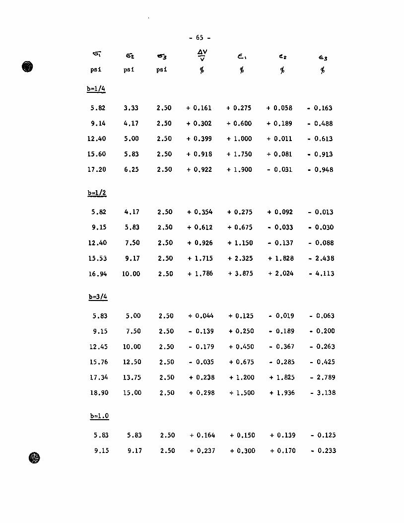
- 65 -
Gl 6'"1. e!r3 AV
6, ez v e.3
psi psi psi ~ ~ ~ ~
b=1/4
5.82 3.33 2.50 + 0.161 + 0.275 + 0.058 - 0.163
9.14 4.17 2.50 + 0.302 + 0.600 + 0.189 - 0.488
12.40 5.00 2.50 + 0.399 + 1.000 + 0.011 - 0.613
15.60 5.83 2.50 + 0.918 + 1. 750 + 0.081 - 0.913
17.20 6.25 2.50 + 0.922 + 1.900 - 0.031 - 0.948
b=1/2
5.82 4.17 2.50 + 0.354 + 0.275 + 0.092 - 0.013
9.15 5.83 2.50 + 0.612 + 0.675 - 0.033 - 0.030
12.40 7.50 2.50 + 0.926 + 1.150 - 0.137 - 0.088
15.53 9.17 2.50 + 1.715 + 2.325 + 1.828 - 2.438
16.94 10.00 2.50 + 1. 786 + 3.875 + 2.024 - 4.113
b=3/4
5.83 5.00 2.50 + 0.044 + 0.125 - 0.019 - 0.063
9.15 7.50 2.50 - 0.139 + 0.250 - 0.189 - 0.200
12.45 10.00 2.50 - 0.179 + 0.450 - 0.367 - 0.263
15.76 12.50 2.50 - 0.035 + 0.675 - 0.285 - 0.425
17.34 13.75 2.50 + 0.238 + 1.200 + 1.825 - 2.789
18.90 15.00 2.50 + 0.298 + 1.500 + 1. 936 - 3.138
b=1.0
5.83 5.83 2.50 + 0.164 + 0.150 + 0.139 - 0.125
9.15 9.17 2.50 + 0.237 + 0.300 + 0.170 - 0.233
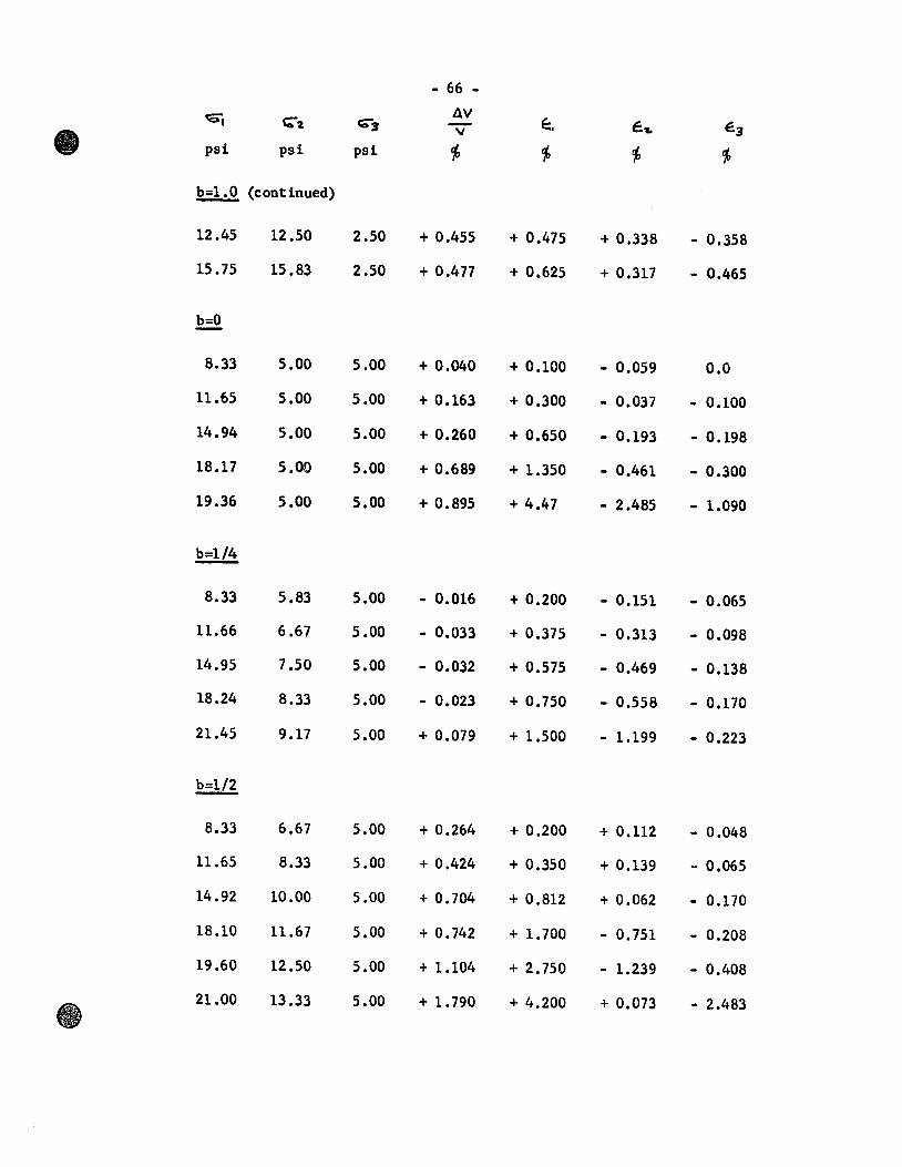
- 66 -
Gj AV ~. ~a C;-3 - é. ... E3 " psi psi psi ~ ~ ~ ~
!?=!.:.Q. (ccnt inued)
12.45 12.50 2.50 + 0.455 + 0.475 + 0.338 - 0.358
15.75 15.83 2.50 + 0.477 + 0.625 + 0.317 - 0.465
~
8.33 5.00 5.00 + 0.040 + 0.100 - 0.059 0.0
11.65 5.00 5.00 + 0.163 + 0.300 - 0.037 - 0.100
14.94 5.00 5.00 + 0.260 + 0.650 - 0.193 - 0.198
18.17 5.00 5.00 + 0.689 + 1.350 - 0.461 - 0.300
19.36 5.00 5.00 + 0.895 + 4.47 - 2.485 - 1.090
b=1/4
8.33 5.83 5.00 - 0.016 + 0.200 - 0.151 - 0.065
11.66 6.67 5.00 - 0.033 + 0.375 - 0.313 - 0.098
14.95 7.50 5.00 - 0.032 + 0.575 - 0.469 - 0.138
18.24 8.33 5.00 - 0.023 + 0.750 - 0.558 - 0.170
21.45 9.17 5.00 + 0.079 + 1.500 - 1.199 - 0.223
b=1/2
8.33 6.67 5.00 + 0.264 + 0.200 + 0.112 - 0.048
11.65 8.33 5.00 + 0.424 + 0.350 + 0.139 - 0.065
14.92 10.00 5.00 + 0.704 + 0.812 + 0.062 - 0.170
18.10 11.67 5.00 + 0.742 + 1.700 - 0.751 - 0.208
19.60 12.50 5.00 + 1.104 + 2.750 - 1.239 - 0.408
21.00 13.33 5.00 + 1. 790 + 4.200 + 0.073 - 2.483
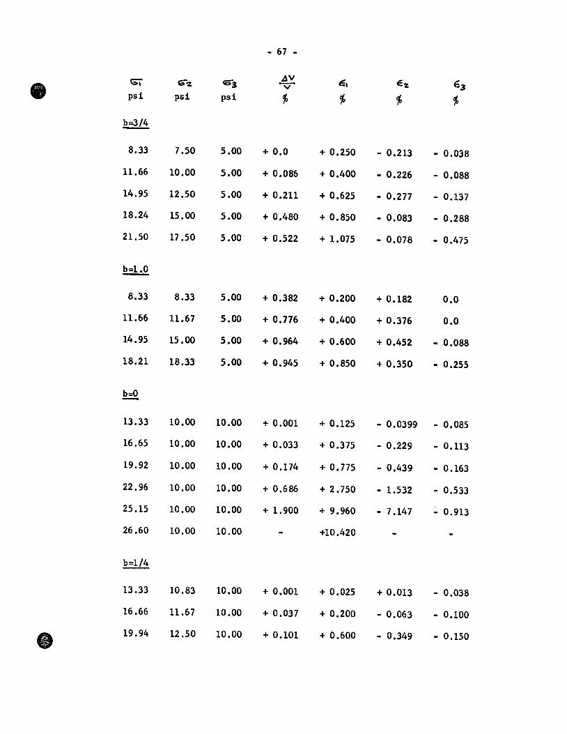
- 67 -
Gï c;;-~ 6"'3 4!1V é, E'Z, 63 -V
psi psi psi cf, cf, cf, cf,
b=3/4
8.33 7.50 5.00 + 0.0 + 0.250 - 0.213 - 0.038
Il.66 10.00 5.00 + 0.086 + 0.400 - 0.226 - 0.088
14.95 12.50 5.00 + 0.211 + 0.625 - 0.277 - 0.137
18.24 15.00 5.00 + 0.480 + 0.850 - 0.083 - 0.288
21.50 17 .50 5.00 + 0.522 + 1.075 - 0.078 - 0.475
~
8.33 8.33 5.00 + 0.382 + 0.200 + 0.182 0.0
11.66 11.67 5.00 + 0.776 + 0.400 + 0.376 0.0
14.95 15.00 5.00 + 0.964 + 0.600 + 0.452 - 0.088
18.21 18.33 5.00 + 0.945 + 0.850 + 0.350 - 0.255
È.=2.
13.33 10.00 10.00 + 0.001 + 0.125 - 0.0399 - 0.085
16.65 10.00 10.00 + 0.033 + 0.375 - 0.229 - 0.113
19.92 10.00 10.00 + 0.174 + 0.775 - 0.439 - 0.163
22.96 10.00 10.00 + 0.686 + 2.750 - 1.532 - 0.533
25.15 10.00 10.00 + 1.900 + 9.960 - 7.147 - 0.913
26.60 10.00 10.00 +10.420
b=1/4
13.33 10.83 10.00 + 0.001 + 0.025 + 0.013 - 0.038
16.66 11.67 10.00 + 0.037 + 0.200 - 0.063 - 0.100
ct 19.94 12.50 10.00 + 0.101 + 0.600 - 0.349 - 0.150
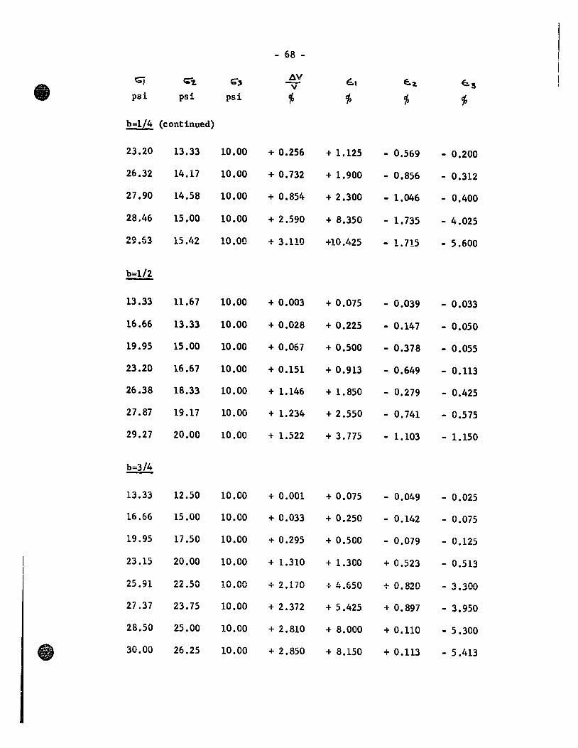
- 68 -
Gj c;"1, C;" AV é, E:.~ E:.3 'T
psi psi psi cf; cf; cf; cf;
b=1/4 (continued)
23.20 13.33 10.00 + 0.256 + 1.125 - 0.569 - 0.200
26.32 14.17 10.00 + 0.732 + 1.900 - 0.856 - 0.312
21.90 14.58 10.00 + 0.854 + 2.300 - 1.046 - 0.400
28.46 15.00 10.00 + 2.590 + 8.350 - 1.735 - 4.025
29.63 15.42 10.00 + 3.110 +10.425 - 1.715 - 5.600
b=1/2
13.33 11.67 10.00 + 0.003 + 0.075 - 0.039 - 0.033
16.66 13.33 10.00 + 0.028 + 0.225 - 0.147 - 0.050
19.95 15.00 10.00 + 0.067 + 0.500 - 0.378 - 0.055
23.20 16.67 10.00 + 0.151 + 0.913 - 0.649 - 0.113
26.38 18.33 10.00 + 1.146 + 1.850 - 0.279 - 0.425
27.87 19.17 10.00 + 1.234 + 2.550 - 0.741 - 0.575
29.27 20.00 10.00 + 1.522 + 3.775 - 1.103 - 1.150
b=3/4
13.33 12.50 10.00 + 0.001 + 0.075 - 0.049 - 0.025
16.66 15.00 10.00 + 0.033 + 0.250 - 0.142 - 0.075
19.95 17.50 10.00 + 0.295 + 0.500 - 0.079 - 0.125
23.15 20.00 10.00 + 1.310 + 1.300 + 0.523 - 0.513
25.91 22.50 11 n nn • 1') 1,n -} J. Lc:.n ..L n S1?n - 3.300 .LV.vv T &..L/V ""'.VJV . v. "' .. ""
27.37 23.75 10.00 + 2 .372 + 5 .425 + 0.897 - 3.950
28.50 25.00 10.00 + 2.810 + 8.000 + 0.110 - 5 .300
30.00 26.25 10.00 + 2 .850 + 8.150 + 0.113 - 5 .413
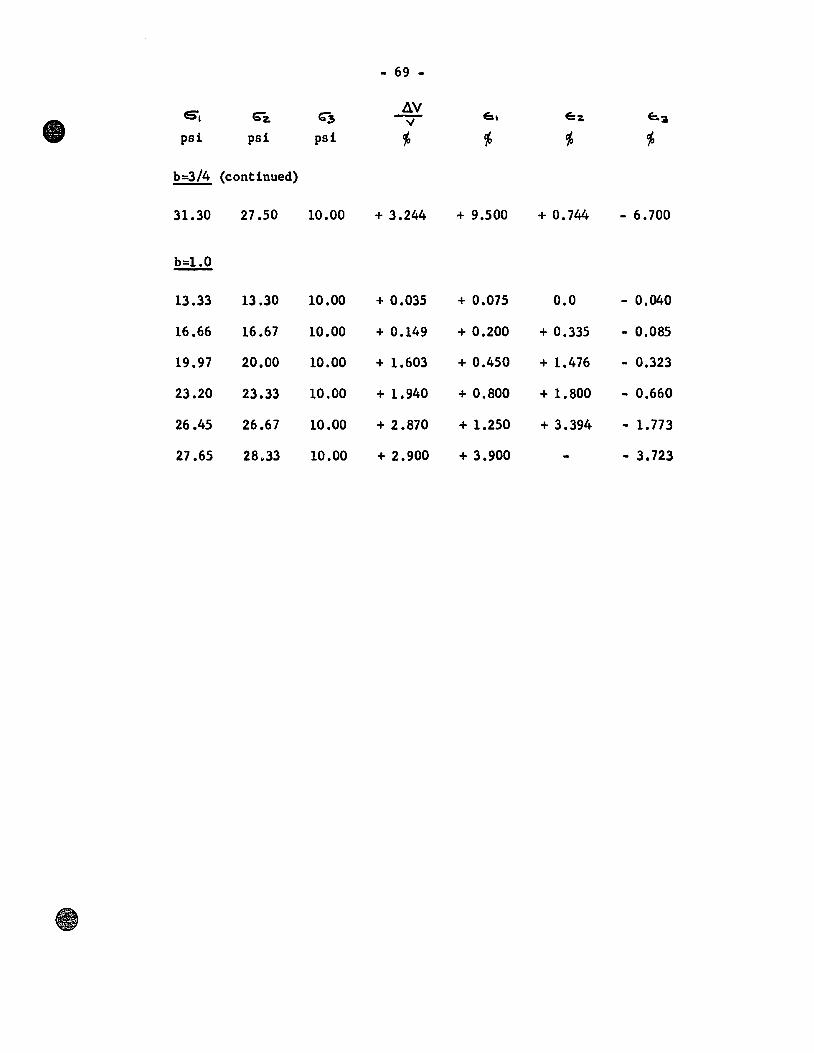
- 69 -
6. 6""z. G""~ AV
6, E:z. E:..3 ~ psi psi psi ~ ~ ~ ~
b=3/4 (continued)
31.30 27.50 10.00 + 3.244 + 9.500 + 0.744 - 6.700
~
13.33 13.30 10.00 + 0.035 + 0.075 0.0 - 0.040
16.66 16.67 10.00 + 0.149 + 0.200 + 0.335 - 0.085
19.97 20.00 10.00 + 1.603 + 0.450 + 1.476 - 0.323
23.20 23.33 10.00 + 1.940 + 0.800 + 1.800 - 0.660
26.45 26.67 10.00 + 2.870 + 1.250 + 3.394 - 1.773
27.65 28.33 10.00 + 2.900 + 3.900 - 3.723
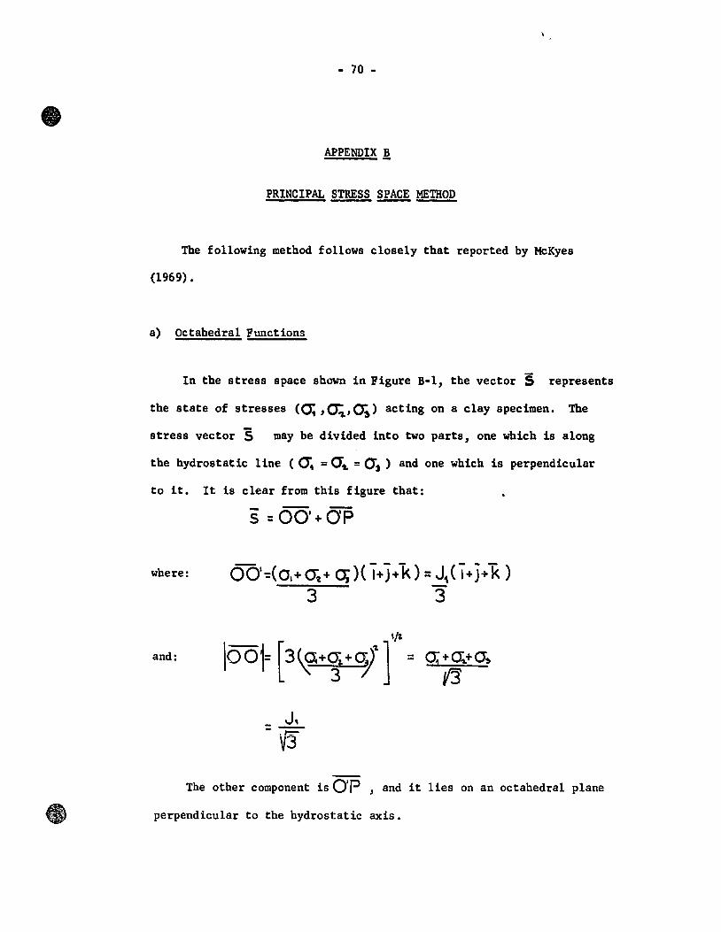
- 70 -
APPENDIX!
PRINCIPAL STRESS SPACE METHOD
The following method follows closely that reported by McKyes
(1969) •
a) Octahedral Functions
In the stress space shawn in Figure B-l, the vector ~ represents
the state of stresses (0; ,~,o;) acting on a clay specimen. The
stress vector!S may be divided into two parts, one which is along
the hydrostatic line (cr. = a", = as) and one which i8 perpendicular
to it. It is clear from thi8 figure that:
where: QQI~(OI+ (it+ 0;)( ï+ J+k) = J1 ( ï+ j+k ) 3 3"
and:
_ J" -'/3
Th h is Q'P d i li h d 1 1 e ot er component ,an t es on an octa e ra pane
perpendicular to the hydrostatic axis.

- 71 -
(0)
( b)
x
1],1<. =unit vectors
0"3
01( Oblique view)
Figure 8-1. Geometry of Principal Stress
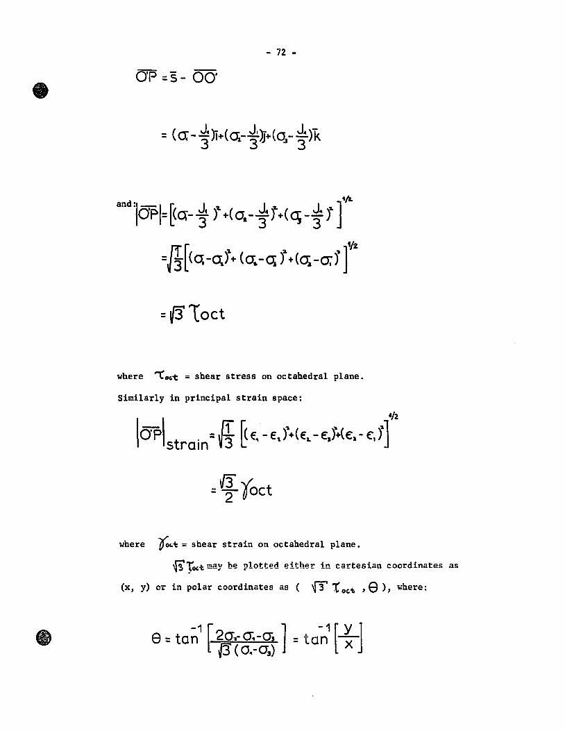
- 72 -
OP =5- 00'
411-and :1- t fJ J 2. J j J] OP =~q- :3 ) +{O,- 34 +(q- 3" t
=~Loct
where "'Coc.t = shear stress on octahedral plane.
Similarly in principal strain space:
=~ foct
where ~Lt = shear strain on octahedral plane.
f3Tô(~ may be plotted either in cartesian coordinates as
(x, y) OL' in polar coordinates as ( f3' t oc.t. ,e), where:

- 73 -
b) The Common Right Section
To examine the adequacy of any yield criterion, it is convenient
to represent experimental data and theoretical predictions in such a
way as the degree of agreement between the two may be immediately seen.
New reduced stress coordinates may be used when yield surfaces, gene-
rated by straight lines, are compared. In Figure B-2, the Mohr-Coulomb
failure surface i8 used as an illustration.
The reduced stress points can be easily described as follows:
X= X
~(o:-o;) J. = ~H J. +3(H) {3
y:. y ~( 2 cr. -cr. - cr.)
~i +(3H =
J1 +3(H) (3
't/2-
~L~t~= I3Toct = ~ q-o;)\(01.- o,j+(a; - 0 4 r ]
~ +/3H J., + 3 (H) f3
e'= e
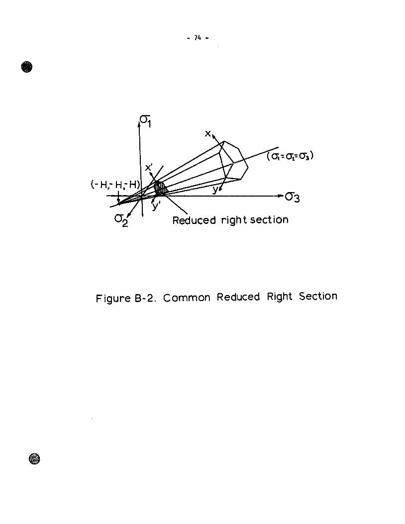
- 74 -
()3
Reduced right section
Figure 8-2. Common Reduced Right Section
- 75 -
APPENDlX ~
GEOLOGICAL HISTORY ~~~
In nature, clay deposits are frequently stratified. The strata
may be composed of soils of similar properties, or of soil types having
different characteristics. The clay is considered anisotropic because
of these physical characteristics.
Leda clay of Eastern Canada belongs to the type described above.
The most important feature of this clay is its sensitivity, that is,
the ratio of undisturbed strength to remoulded strength.
In view of the obvious importance of soil structure to sensitivity
and shear strength, it is worth reviewing the geologic history of Leda
clay.
During the Pleistocene, when the recession of the continental iee
sheets was going on, conditions were highly favourable to the develop
ment of widespread marginal lakes. At the time of maximum extension of
the ice the less mountainous parts of the underlying floors were
depressed into shallow regions by the isostatic effect of the load of
ice. In the late Pleistocene time, the crust was gradually unloaded
and isostatic recovery worked in from the margins of these depressions
(Karrow7 1960). Consequently, for thousands of years there were large
aëeas, abaüdônned by ice, that slopeà towaràs anà beneath the receding
ice fronts. Many of these became giant lakes, while others were
invaded by the sea. As the ice sheets were retreating and because of
the isostatic balance, lands, that were once depressed by several
- 76 -
hundred feet, started to rebound and today these sediments are often
found above cea level (Karrow, 1960; Allen and Johns, 1960).
elays with properties similar to those of Leda clay are the well
known Scandinavian quick clays. These soils have been investigated by
Rosenquist as early as 1946, Osterman (1960), Bjerrum (1961) and others.
The sensitivity of Norwegian marine clays is strictly related to
the salt concentration of the pore fluide This is explained by the
"leacbing effect" on sensitivity which 1a based Oil the fact that sedi
mentation took place in sea water or brackish water (Rosenquist, 1946;
Skempton and Northey, 1952; Bjerrum and Rosenquist, 1956).
When the sedimentation of these clays had ceased and if the depo
sits were subsequently invaded by fresh waters, considerable leaching
occurred. The general configuration of the minerals in clay, from
which the salts are leached out, may remain unalteredj and if the ori
ginal structure is not disturbed, the clay will exhibit a considerable
shear strength. When leaching occurs, the thickness of the adsorbed
water layers decreases; hence more free water is available in the
interstitial pores. Then, on remoulding, this clay will exhibit a
shear strength lower than that of the original clay. This hypothesis
to explain t~e sensitivity of Norwegian clays was confirmed by Skempton
and Northey (1952).
Leda clay is thought to have been formed in the same way, but
erosion by fresh waters and subsequent redeposition are responsible for
its flocculated structure. This open structure is attributed to resi
dual cations from the original marine deposit (Eden and Crawford, 1957).
Also, it is believed that factors other than leaching have contributed
- 77 -
to the sensitivity aince there appears to be no correlation between
salt concentration and sensitivity with depth (Crawford, 1960).
Eden and Crawford (1965) report pore water salt concentrations
of the order of one to two grams per liter, while a wide range of
salt concentrations has been reported for Norwegian marine clays
(Bjerrum, 1954). However, more conclusive data about existing salt
concentrations are needed since it has been reported that in areas
where majo~ slides occurreâ, Îor example, Nicolet, Quebec, in 1956
where a high salt concentration was found (Crawford, 1960).
In 1953, Lambe presented schematic diagrams of the structure of
clays. For undisturbed marine clays, an open structure similar to
the cardhouse model postulated by Goldschmidt (1926) was shown, whereas
in fresh water sediments, the structure was thought somewhat denser and,
in remoulded clays, was supposed to have a high degree of parallelism
(Figure C-l).
In 1957, Tan presented a schematic picture of a clay mineraI
arrangement dominated by edge-to-face contacts (Figure C-2). Today,
by means of electron microscopy, it is possible to prove that the
mineraI arrangement of undisturbed marine clays corresponds to the
cardhouse structure of Goldschmidt and Lambe and, in fact, exactly
agrees with the theoretical work of Tan, (Lambe, 1960).
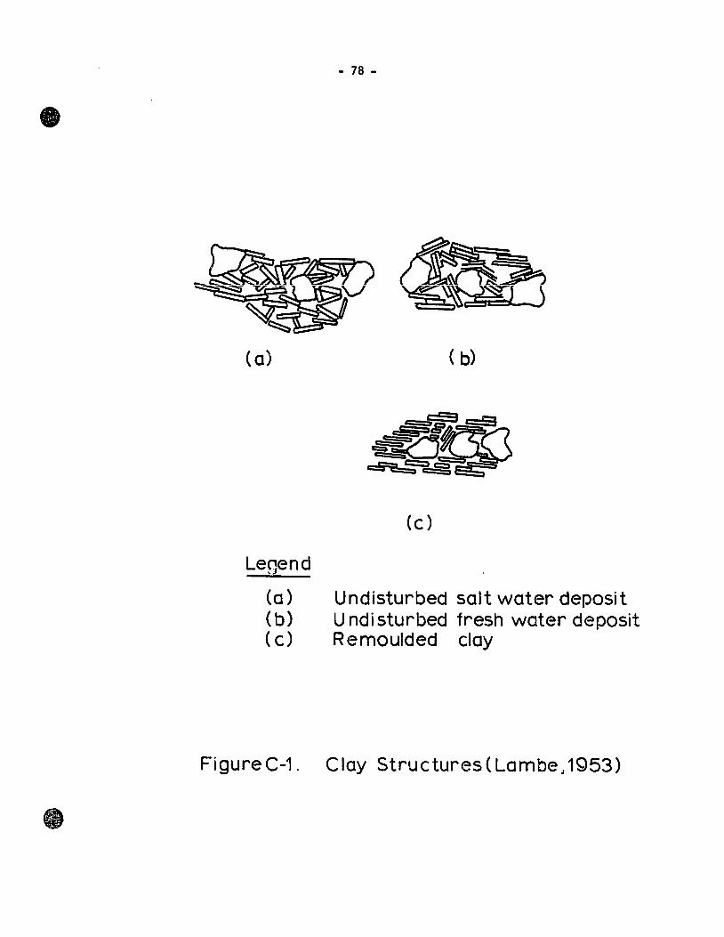
Legend
(a) (b) (c)
Figure C-1.
- 78 -
(c)
Undisturbed salt water deposit U ndi sturbed fresh water deposit Remoulded clay
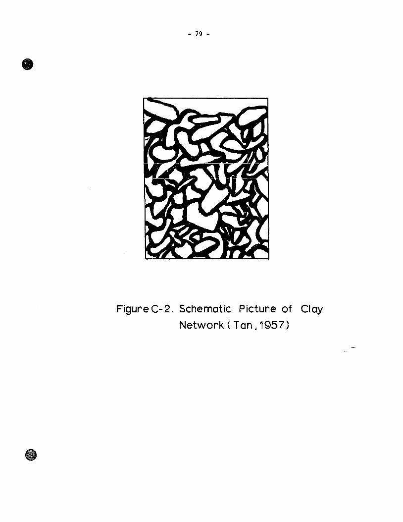
- 79 -
FigureC-2. Schematic Picture of Clay
Network ( Tan J 1Q57)
- 80 -
APPENDIX !!
OPTICAL METHOD
In order to investigate the fabric of undisturbed, consolidated
and failed clay samples, an optical method for the direct observation
of the clay surface was developed.
To apply standard optical procedures to the study of clay fabric,
it was necessary to replace the soil moisture with a high molecular
weight polyethylene glycol compound (Carbowax 1000). This mate rial is
hard at room temperature, melts at 450C and is soluble in water in all
proportions. Small samples oj~ the clay were placed in the melted
material in the manner described by Mitchell (1956) and Leitch (1967).
Since at the end of six days the water in the clay was replaced by
the melted Carbowax, the samples were removed from the bath and allowed
to cool. Thin clay sections of 25-micron thickness were then cut by
me ans of a medical microtome knife (teitch, 1967) and were viewed in a
polarizing microscope. With such a microscope there are various means
of analyzing the orientation of clay particles owing to the difference
in refractive indices between tbe optical axes of the individual clay
platelets. This property, known as birefringence, causes various inter
ference colours to be observed, depending upon the nature, thickness and
relative orientation of clay particles (Kerr, 1959).
The absence of past work using interference colour technique in
clay fabric studies renders it difficult to be exact in the evaluation
of the results; however, single crystal theories may be applied
- 81 -
(Mitchell, 1956; Leitch, 1967; Yong and Japp, 1968).
The crossed-nico1s method is used and the gypsum red plate is
introduced between the thin section and the ana1yzer. The procedure
is out1ined be10w and fo110ws c10se1y that of Yong and Japp (1968).
If the clay partic1es are oriented in the manner shown in Figure
D-1(a), then the field of view will have a uniform red co10ur. If the
clay partic1es are inc1ined with respect to the incoming 1ight, then
the field of view will appear as shades of green and orange.
If the clay partic1es are oriented as shown in Figure D-1(b),
the field of view will have a greenish co1our; and if the clay parti
c1es are oriented at about 900 c10ckwise from the position in Figure
D-1(b), the observer will see shades of orange and ye11ow. This condi
tion is shown in Figure D-1(c).
F10ccu1ated and random1y oriented clay fabrics will show co1our
mixtures ranging between green and ye110w. For undisturbed clay speci
mens, the co10urs wou1d not be as uniform1y distributed as in the case
of oriented samp1es. Darker and 1ighter regions are characteristics
of these c1ays, indicating a f10ccu1ated structure.
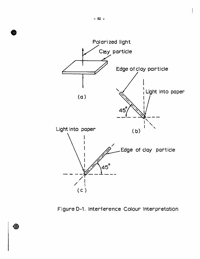
- 82 -
Polari zed light
ClelY particle
Edge of clay pcrticle
/ (a)
Light into paper ( b)
1 1 1
1 1 1
Edge of clay particle
Figure D-1. Interference Colour Interpretation
- 83 -
1!§! QE. ~ERENCES
Allen, V. T. and Johns, w. D., "C1ays and clay mineraIs of New Eng1and and Eastern Canada", l!!:!!!.. ~. ~. ~., 71:75-86, 1960.
Bilodeau, P. M., ''The N:ico1et Lands1ide", Proceedings ~ Canadian §2!l Mechanics Conference, TM46:11-13, 1956.
Bishop, A. W., "The strength of soils as engineering materia1s", Geotechnique, 6th Rankine Lecture, 16:91-128, 1966.
Bishop, A. W. and Henke1, D. J., I!!.! Measurement 2t Soil Properties !!!. ~ Triaxia1 Test, 2nd ed., Arnold, London, 1962, 190 pp.
Bjerrum, L., "Geotechnica1 properties of Norwegian marine c1ays", Geotechnique, 4:2:49-69, 1954.
Bjerrum, L., '1he effective shear strength parameters of sensitive c1ays", Proceedings ~ M. ~. !2!l~. ~. Eng., Paris, France, 1;23-28, 1961.
Bjerrum, L. and Rosenquist, 1. Th., "Sorne experiments with artificia1 sedimented c1ays," Geotechnique, 6 :3: 124-136, 1956.
Brydon, J. E. and Patry, L. M., '~inera10gy of Champlain Sea Sediments and a Rideau Clay Soil Profile", Canadian l. ~ ~., 41:169-181, 1961.
Collins, A., Lands1ides !!!. C1ays, (tr.ans1ated by W. R. Schriever), University of Texas Press, Austin, Texas, U. S. A., 1956.
Con10n, R. J., ''Landslide on the To1nustouc River, Quebec", Canadian Geotechnica1 Journal, 3:3:113-144, 1966.
Corforth, D. H., "Sorne experiments on the influence of strain conditions on the strength of sand", GeotechniQue. 17:2:143-167, 1964.
Crawford, C. B., Discussion to ''Canadian Pleistocene Marine Clays" by P. F. Karrow, proceedings ~ Can~dian ~ Mechanics Conference, TM69:103-105, 1960.
- 84 -
Crawford, C. B., "The influence of strain on shearing resistance of sensitive clay", Proceedings ASTM. 61: 1250-76, 1961.
Crawford, C. B., "Cohesion in an undisturbed sensitive clay", ~technique. 13:2:132-145, 1963.
Crawford, C. B., "The resistance of soil structure to consolidation", Canadian Geotechnica1 Journal. 2:2:90-97, 1965.
Crawford, C. B. and Eden, W. J., "A comparison of 1aboratory resu1ts with in-situ properties of Leda clay", Proceedings !!!.E!!!!!l. ~. ~~. ~. Eng., Montreal, Canada, 1:31-35, 1965.
Crawford, C. B. and Eden, W. J., "Stability 'of natura1 slopes in sensitive c1ays", Proceedings ~ 93, SM4:419-436, 1967.
Eden, W. J., ''The Bawkesbury Lands1ide", Proceedings ~ Canadian §2!! Mechanics Conference. TM46:14-22, 1956.
Eden, W. J. and Brydon, J. E., "Some observations on the measurement of sensitive claya", Proceedings ASDf, 61:1239-1249, 1961.
Eden, W. J. and Crawford, C. B., '~eotecbnica1 properties of Leda clay in the ottawa region", Proceedings Fourth !!!l. ~. !2.!! Mech. ~. Eng., London, 1:22-27, 1957.
Gadd, N. R., "Geo10gica1 aspects of Eastern Canada flow slides", ~oceedings ~ Canadian !2!l Mechanics Conference, TM46:2-8, 1956.
Go1dschmidt, V. M., ''Unders8ke1ser over 1ersedimenter" (Investigations of sedimentary c1ays), Nordisk Jordbrugsforskning, proceedings Third Conference, Oslo, Norway, 434-445, 1926.
Go1dstein, M. and Ter-Stepanian, G., "The 10ng-term strength of c1ays and depth creep of slopes", Proceedings Fourth !!!!. ~. ~ ~. ~. Eng., London, 2:311-314, 1957.
Grim, R. E., "Physico-chemica1 properties of so11s: clay mineraIs", proceedings ~.§2., SM2:1-18, 1959.
Benke1, D. J., Oral presentation. Symposium on Advances in Soi1 Mechanics, Waterloo, Ontario, Canada, 1968.
Benke1, D. J. and Wade, N. B., "Plane strain tests on a saturated remoulded clay", Proceedings ~ 92, SM6:67-80, 1966.
- 85 -
Hvors1ev, M. J., "Conditions of faUure for remou1ded cohesive soUs", Proceedings llE!!~. Q2.!:
- 86 -
Lafeber, D., Discussion ta 'Microscopic structures in kaolin subjected ta direct shear", by N. R. Morgenstern and J. S. Tchalenko, Geotechnique. 18:379-382, 1968.
Lambe, T. W., ''The structure of inorganic soUs", Proceedings ~ J.!, 1953.
Lambe, T. W., "The structure of compacted clay", Proceedings ~ ~ SM2:l654:l-34, 1958.
Lambe, T. W., "Physico-chemical pl'operties of soUs: ro1e of sail technology", proceedings ~ §2., SM2:55-70, 1959.
Lambe, T. W., "A mechanistic picture of shear strength in clay", ASCE Research Conference on Shear Strength of Cohesive Soi1s, Boulder, Colorado, U. S. A., 555-580, 1960.
Lambe, T. W. and Martin, R. T., "Composition and engineering properties of sail (III) ", Proceedings HRB 34:566-582, 1955.
Lambe, T. W. and Martin, R. T., "Composition and engineering properties of soU (IV)", Proceedings HRB35:661-677, 1956.
Leitch, H. C., "The rate dependent mechanism of shear failure in è1ay soils;' McGi11 University, Montreal, Canada, Ph.D. Thesis, 1967.
Leitch, H. C. and Yong, R. N., 'The r~t~ dependent mechanism of shear failure in clay soUs", SoU Mechanics Series !2.. ll, Report to Defence Research Board of Canada, Report No. D. Phys. R. (G), Misc. 28, 1967.
Lo, K. Y. and Milligan, V., "Shear strength properties of two stratified clays", Proceedings ASCE ll., SMl:l-lS, 1967.
McKyes, E., "Intermediate principal stress effects on the yielding of a clay", McGill University, Montreal, canada, Master of Engineering Thesis, 1967.
McKyes, E., ''Yielding of a remoulded clay under comp1ex stress states", MeGill University, Montreal, Canada; Ph.D. Thesis; 1969.
Meyerhof, G. G., SUIl1IIary of "The mechanism of flow slides in coheslve soUs", Proceedings !Q!!!. Canadian SoU Mechanics Conference, TM46:9-l0, 1956.
- 87 -
Mitchell, J. K., "The fabric of natural clays and its relation to engineering properties", Proceedings HRB 35:693-713, 1956.
Morgenstern, N. R. and Tchalenko, J. S., '~icroscopic structures in kaolin subjected to direct shear", Geotechnique, 17:4:309-329, 1967.
Morgenstern, N. R. and Tchalenko, J. S., '~icrostructural observations on shear zones from slips in natural clays", Proceedings Geotech~ Conference, Oslo, Norway, 153-158, 1967.
Osterman, J., "Notes on the shearing resistance of soft clays", ~ Polytechnica Scandinavica, 263/1959, Stockholm, Sweden, 22 pp., 1960.
Parry, R. H. G., '~atent interparticle forces in clays", Nature, 183: 538-539, 1959.
Penner, E., "Sensitivity in Leda clay", Nature, 197:347-348, 1963.
Quigley, R. M., "The engineering properties of iUite related to fabric and pore water composition", Proceedings ~ Canadian !2!l Mechanics Conference, TM82:2l-42, 1962.
Quigley, R. M. and Thompson, C. D., ''The fabric of anisotropically consolidated sensitive marine clay", Canadian Geotechnical Journal, 13:2:61-73, 1966.
Rendulic, L., "Relation between void ratio and effective principal stresses for a remoulded silty clay", Proceedings ~~. ~. Soil ~. ~. Eng., Cambridge, 3:48-51, 1936.
Rochette, P. A., "Experimental and theoretical investigation on the engineering properties of Canadian natural clay deposits", Proceedings ~ Canadian ~ Mechanics Conference, TM46:27-34, 1956.
Roscoe, K. H., Schofield, A. N. and Wroth, C. P., "On the yielding of so11s", Geotechnique, 8:1:22-53, 1958.
Rosenquist,!. Th., "Am le ires kvikkaktighet" (The sensitivity of clays), Statens Vegvesen, Veglaboratoriet, Meddelelse, No. 4:5, 1946.
Rosenquist,!. Th., "Considerations on the sensitivity of Norwegian quick clays", Geotechnique, 3:5:~95-200, 1953.
- 88 -
Rosenquist, 1. Th., "Investigations in the clay~electrolyte water system", Norwegian Geotechnical Institute, Pub. No. 9, Oslo, Norway, P. 125, 1955.
Rosenquist, 1. Th., "Phys ico-chemical properties of so11&: so11-water systems", Proceedings ~.§2., SM2 :31-53, 1959.
Rosenquist, 1. Th., '1he influence of physico-chernical factors upon the mechanical properties of clays", Proceedings ~ Natl onal Conference ~ Clays ~ Clay MineraIs, Lafayette, Indiana, U. S. A., pergamon Press, New York, 9:12-27, 1962.
Schmertmann, J. H. and Osterberg, J. O., "An experimental study of the development of cobesion and friction with axial strain in saturated cohesive so11s", ASCE Research Conference on Shear Strength of Cohesive Soils, Boulder, Colorado, U. s. A. 643-694, 1960.
Schmertmann, J. H. and BaIl, J. R., '~ohesion after non-hydrostatic consolidation", proceedings ~ §L, SM4:39-60, 1961.
Shibata, R. N. and Karube, D., "Influence of the variation of the intermediate principal stress on mechanical properties of normally consolidated clays", Proceedings §.!!!!!.!!!!. Q2!!!.. !2!!.~ ~. ~. Eng., 1:359-363, 1965.
Skempton, A. W. and Northey, R. D., ''The sensitivity of claya", Q!2.technique, 3:1:30-53, 1952.
Soderman, L. G., Kenney, T. C. and Loh, A. K., "Geotechnical properties of glacial clays in Lake St. Clair region of Ontario", Proceedings ~ Canadian ~ Mechanics Conference, TM69:55-87, 1960.
Soderman, L. G. and Quigley, R. M., "Geotechnical properties of three Ontario clays", Canadian Geotechnical Journal, 11:2:167-189, 1965.
Spence, R. A. and Glynn, T. E., "Shear characteristics of a marine clay", Proceedings ~ ~ SM4: 85-107, 1962.
Tan, T. K., "Structure Mechanics of Clays", Academia Sinica. Soil Mechantes Laboratory, !nstitute Civ. Eng. end Arch. Harbin, China, 1957.
Terzaghi, K., "Undisturbed clay samples and undisturbed clays", Journal Boston ~. Civ. Engrs., 28:211-231, 1941.
- 89 -
Townsend, D. L., Discussion to '~andslide on the Tolnustouc River, Quebec", by R. J. Conlon, Canadian Geotechnical Journal, 4:3: 351-352.
Wu, T. H., Loh, A. K. and Malvern, L. E., "Study of faUure envelope of soUs", proceedings ~.§2., SM1:145-l82, 1963.
Yong, R. N. and Warkentin, B. P., Introduction12!2!l behaviour, Macmillan, New York, 1966, 451 pp.
Yong, R. N. and McKyes, E., 'Yielding of a clay in a complex stress field", Third panameriean Conf. Soil. Mech. FOUild. Eng., 1:131-148, 1967.
Yong, R. N. and Japp, R. D., "Soil water relationships and their engineering applications", Report to Cornell Aeronautical Laboratory Inc. on Contract S-68-5, 1968.