Embed Size (px)
Citation preview

Voltage Interruptions on 140 Bus Power Grid Performance Under Faults-DFIG Based Wind Power Generation System Control and Operation by Integrated E-STATCOM Improves Power Quality
K.V. Ramana Reddy*, Ravi. K**
School of Electrical Engineering, Vellore Institute of Technology, Vellore
*[email protected] **[email protected]
Abstract
The arrival of new developments in the field of power electronics circuit’s applications in power systems builds new control strategy to improve voltage quality for power grid by overcome interruptions. Wind energy resources are unconventional resources and get advanced problems to power grid when it is connected. Uncertainty of load sharing, peak energy management, climatic conditions, wind velocity and wind energy injected into power grid leads many of power quality problems on power grid based on the existing guidelines specified in IEC-61400 standard. This system plans efficient operation of DFIG to eliminate the voltage collapse and mismatch frequency to power grid. The DFIG connected diode rectifier and rotor side converter wind generator works as an Efficient Static Synchronous Compensator (E-SATCOM) for supplying the demand of reactive power for power grid to mitigate PQ problems. The benefit of using a combined controller was verified by simulink/Matlab and its simulated results used Doubly Fed Induction Generator (DFIG), wind Turbine. This simulation results gives good quality transient and stable state response to manage and support reactive power for both symmetrical and unsymmetrical faults in connection of grid codes to provide continuous quality of power supply, multiple wind generators are required for 140 bus power grid.
Keywords: (Efficient) E-STATCOM, Doubly Fed Induction Generator; Rotor Side Converter; Diode Rectifier and140- bus power grid test power system.
1. Introduction
Many research works and its discussion on conventional fuel like oil reserves were decreasing through out the world. Now most countries are turn towards renewable energy and make saving its potential. The energy demand of India can hits roughly 701 metric tons of oil equivalent in year of 2015 and its growth is expected to 129 percentage in 2035, now india is trying to take wind power back to the market. [1].
1.1 Literature review and motivation Wind Energy System (WES) will be one of the most promising renewable energy systems
in the near future. The costs of the installed WES are continuously decreasing worldwide because of falling component average selling prices [2]. Based on the statistics of the ICRA on December 20, 2017 the tariff discovered in the reverse auction under the second Ministry of New Renewable Energy (MNRE) scheme conducted by SECI in October 2017 declined by 24 per cent to Rs 2.64 per unit as against Rs 3.46 per unit discovered in the first MNRE scheme[3].
Preprints (www.preprints.org) | NOT PEER-REVIEWED | Posted: 6 August 2018 doi:10.20944/preprints201808.0121.v1
© 2018 by the author(s). Distributed under a Creative Commons CC BY license.

The ministry of New and renewable energy and power, Indian minister R K Singh told that the indian government plans to generate 5 Giga Watts (GW) power from offshore wind energy on National energy conservation day. Minister exudes his confidence of surpass power and its target of 175 Giga Watts share of renewable energy capacities by 2022 and changing it to 200 Giga Watts on 14 December 2017.
1.2 The DFIG System
During the normal operation, Doubly Fed Induction Generator (DFIG) generates a continuous electrical power. Mainly the variations in power caused by the consequence of instability, wind cut off speed, tower shadows and intelligent system changes power network. It is important to manage such variations otherwise it leads power quality problems for example flickers, electrical sag, voltage interruptions, transients and harmonics. Power quality issues are encountered at unconventional generation system, 140 bus power grid and even in micro grid distribution system.
Doubly Fed Induction Generator (DFIG) is one simple method of wind energy generating system is directly connected to the power grid. The inbuilt advantages like low cost and high robustness for Doubly Fed Induction Generator (DFIG) were popular throughout world. The required reactive power demand for magnetization was done by Doubly Fed Induction Generator (DFIG). The generated active power absorbed by the reactive elements distributed entire power system network and given a path for active power transmission. The generated power of Doubly Fed Induction Generator (DFIG) can varies by wind variation, Increasing disturbances in 140 bus power grid require a proper control scheme for active power generation with Doubly Fed Induction Generator (DFIG) and compensate fluctuations and interruptions demanded reactive power at 140 bus power grid.
An Efficient – Static Synchronous Compensator (E - STATCOM) and Doubly Fed Induction Generator (DFIG) proposed a control strategy to improve power quality on 140 bus power grid. The stator of Doubly Fed Induction Generator directly connected to 140 bus power grid and has the following objectives.
Power quality of grid maintains the unity power factor at the source side.
The controller at the rotor side converter has fast and dynamic response
The demand of the reactive power was done by E-STATCOM to Doubly Fed Induction Generator (DFIG) and then to load side.
Grid code requirements for the grid connection and operation of wind farms are discussed in [4].
1.3 paper organization
The rest of the paper is planned as follows. Wind energy integration for power grid explains in section II. The Section III describes the desired 140 bus test power system. Then Section IV explains control strategy to improve power quality. Sections V and VI describe the system DFIG and E-STATCOM performance and conclusion correspondingly.
2. Wind energy Integration for power grid
Preprints (www.preprints.org) | NOT PEER-REVIEWED | Posted: 6 August 2018 doi:10.20944/preprints201808.0121.v1
Now a day’s every common person require electrical energy with out electrical energy it is difficult to imagine and lead the human life. House hold appliances onwards up to industrial applications required electrical energy. To provide continuous electrical power to every common citizen is not an easy task, even at year of 2018 still suffers lack of three phase electrical power. Even to provide and manage eight hours three phase electrical power, switching substations are used to switch same power from one area to another area for agriculture purpose.
As by depletion of fossil fuels day to day, we target Non conventional energy resources are alternative sources and need of the day to support industrial power grids as the number of fault count increases on industrial grid power system the demand of reactive power increases. These sources are freely available, finally wind energy is free source Safe and environmentally clean renewable electrical power compare with fossil fuel and nuclear electrical power generation. The modern advancements like Maximum Power Point Tracking System (MPPT) traps maximum wind energy from last 2 to 3 decades was noticed and hold it a tough aggressive position when compare with conventional power network system.
So in upcoming day’s lot of additional domestic and industrial electrical machinery application load increases and the demand of electrical power increases the available grids are become weak grids under average and peak load conditions. Wind energy is only one popular available source compare to rest of all sources every where for free of cost for 24 hours and 365 days.
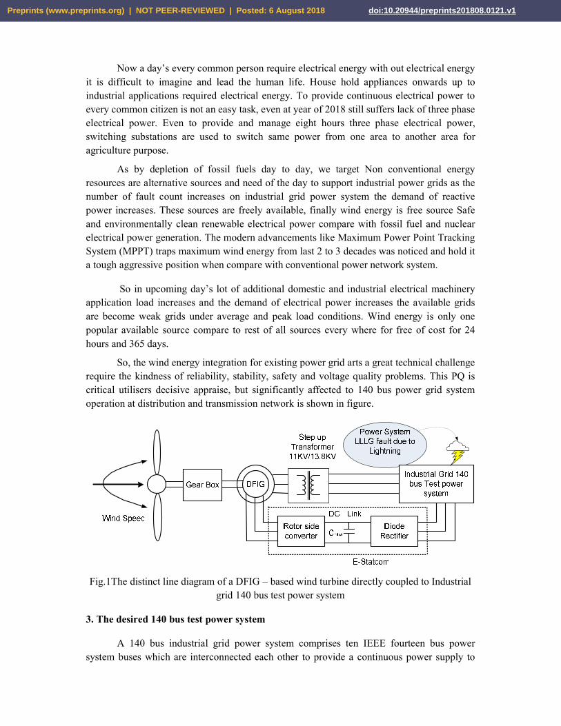
So, the wind energy integration for existing power grid arts a great technical challenge require the kindness of reliability, stability, safety and voltage quality problems. This PQ is critical utilisers decisive appraise, but significantly affected to 140 bus power grid system operation at distribution and transmission network is shown in figure.
Fig.1The distinct line diagram of a DFIG – based wind turbine directly coupled to Industrial grid 140 bus test power system
3. The desired 140 bus test power system
A 140 bus industrial grid power system comprises ten IEEE fourteen bus power system buses which are interconnected each other to provide a continuous power supply to
Preprints (www.preprints.org) | NOT PEER-REVIEWED | Posted: 6 August 2018 doi:10.20944/preprints201808.0121.v1
load with other parallel conductor even at case any fault existed on power system as shown in figure[4].
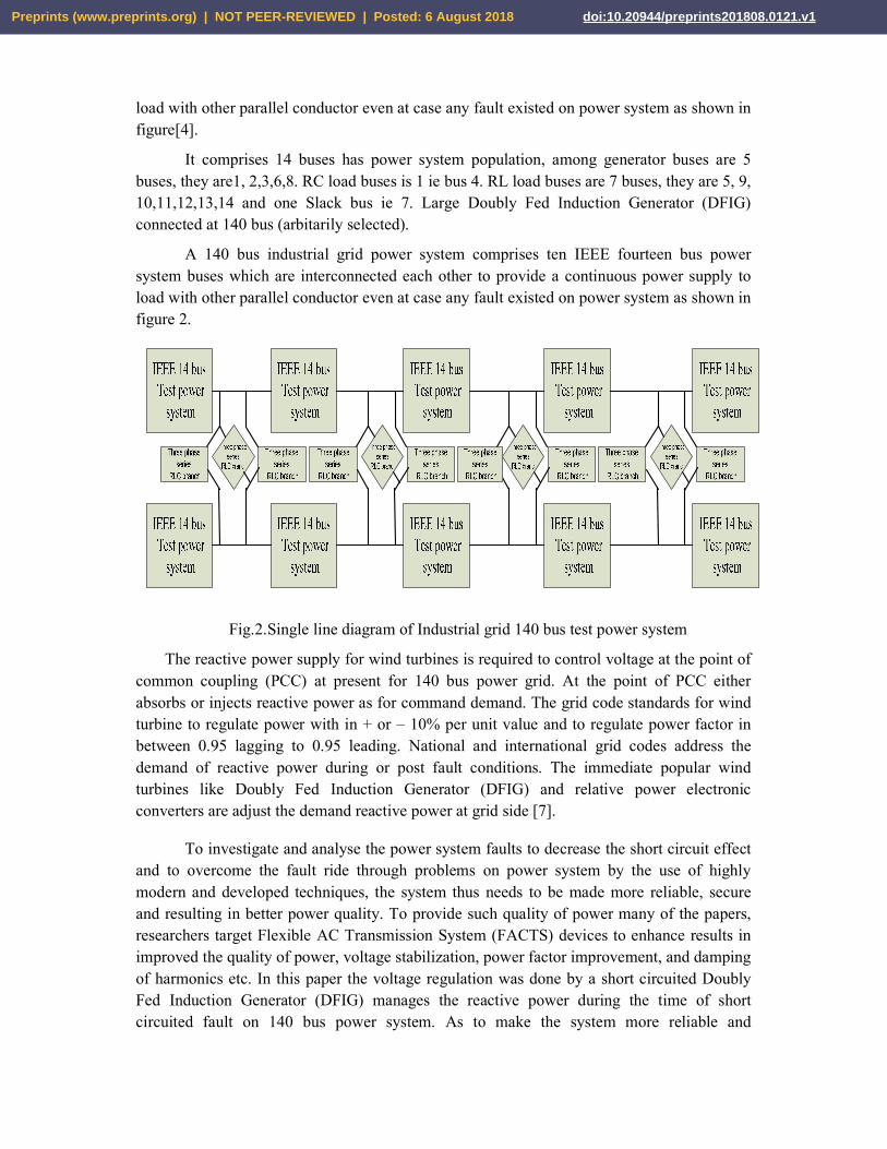
It comprises 14 buses has power system population, among generator buses are 5 buses, they are1, 2,3,6,8. RC load buses is 1 ie bus 4. RL load buses are 7 buses, they are 5, 9, 10,11,12,13,14 and one Slack bus ie 7. Large Doubly Fed Induction Generator (DFIG) connected at 140 bus (arbitarily selected).
A 140 bus industrial grid power system comprises ten IEEE fourteen bus power system buses which are interconnected each other to provide a continuous power supply to load with other parallel conductor even at case any fault existed on power system as shown in figure 2.
Fig.2.Single line diagram of Industrial grid 140 bus test power system
The reactive power supply for wind turbines is required to control voltage at the point of common coupling (PCC) at present for 140 bus power grid. At the point of PCC either absorbs or injects reactive power as for command demand. The grid code standards for wind turbine to regulate power with in + or – 10% per unit value and to regulate power factor in between 0.95 lagging to 0.95 leading. National and international grid codes address the demand of reactive power during or post fault conditions. The immediate popular wind turbines like Doubly Fed Induction Generator (DFIG) and relative power electronic converters are adjust the demand reactive power at grid side [7].
To investigate and analyse the power system faults to decrease the short circuit effect and to overcome the fault ride through problems on power system by the use of highly modern and developed techniques, the system thus needs to be made more reliable, secure and resulting in better power quality. To provide such quality of power many of the papers, researchers target Flexible AC Transmission System (FACTS) devices to enhance results in improved the quality of power, voltage stabilization, power factor improvement, and damping of harmonics etc. In this paper the voltage regulation was done by a short circuited Doubly Fed Induction Generator (DFIG) manages the reactive power during the time of short circuited fault on 140 bus power system. As to make the system more reliable and
Preprints (www.preprints.org) | NOT PEER-REVIEWED | Posted: 6 August 2018 doi:10.20944/preprints201808.0121.v1

economical the Doubly Fed Induction Generator (DFIG) connected one Diode Fed rectifier system to convert the available Alternating current into direct current and One Voltage Source Converter to convert the Direct current into Variable Alternating current to mange the short circuited bus voltage was done by Efficient STATCOM, to provide the continuous power supply and to improve the quality of power.
4. Control Strategy for power quality improvement
In this paper DFIG is an uneven speed individual induction machine and widely used as bulky wind turbine generator in modern days. It has a benchmark standard wound type rotor, induction machine whose stator winding is mainly short circuit to the 140 bus test power grid and its rotor winding directly given to Rotor Side Converter (RSC) is connected to DC link exists between Diode rectifier and Rotor Side Converter (RSC) (AC - DC - AC). This converter conversion AC - DC - AC control circuit fed with Doubly Fed Induction Generator (DFIG) operate in both modes like sub synchronous mode (positive slip (S) greater than zero) and above synchronous mode (negative slip (S) less than zero) operating region. Depending on the type of the power quality problem on 140 bus power grid, the variable power fed to rotor of Doubly Fed Induction Generator (DFIG) operates in either sub synchronous / above synchronous modes and rated induced voltage injected in fault affected bus to restore voltage and the rest of close buses to 140 bus, whose voltage sags are overcome by manage the additional reactive power to power grid [6].
Slip (S) =Ns − N
Ns∗ 100
Ns = Synchronous Speed in rpm N = rotational speed in rpm
4.1 Doubly fed Induction generator model
The Doubly Fed Induction Generator (DFIG) is a variable speed operating system whose variable speed restricted to operate in a range with ± 30 percent of a synchronous speed. So it gives an attractive solution for a 140 bus power grid, power quality problems. In between Diode rectifier and Rotor Side Converter (RSC) converter to overcome harmonics DC-link capacitor is placed. Rotor Side Converter (RSC) controls the speed of Doubly Fed Induction Generator (DFIG). This DFIG operates either motor as well as a generator together sub synchronous and above synchronous operating speed with the help of Rotor Side Converter (RSC) control. The two operating modes like sub-synchronous speed and above synchronous speed are preferred to generate wind power.
The demand of the reactive power additionally increases as by increasing the count of power quality and short circuit problems on power system .The RSC activate and increases the RSC converter current to DFIG as to meet the grid code values. The RSC current also increases when the speed of the DFIG operates at sub synchronous speed and decreases at over - synchronous speed and machine configuration is shown in figure.
Table.1
Preprints (www.preprints.org) | NOT PEER-REVIEWED | Posted: 6 August 2018 doi:10.20944/preprints201808.0121.v1
The doubly fed induction generator parameters are found in table.1
Parameter Value
Nominal power 4.6MVA
input line-to-line voltage 11 KV
Frequency 50Hz
Rotor voltage 3000
Pitch angle 27
KP 150
Friction factor 0.01p.u
4.2 Control of Rotor Side Converter (RSC)
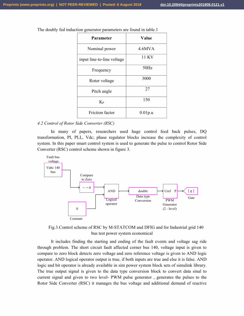
In many of papers, researchers used huge control feed back pulses, DQ transformation, PI, PLL, Vdc; phase regulator blocks increase the complexity of control system. In this paper smart control system is used to generate the pulse to control Rotor Side Converter (RSC) control scheme shown in figure 3.
0
Vabc 140 bus
Fault bus voltage
Constant
AND
Logical operator
~ = 0
Compare to Zero
Uref P
PWM Generator(2 - level)
double
Data type Conversion
[ g ]
Gate
Fig.3.Control scheme of RSC by M-STATCOM and DFIG and for Industrial grid 140 bus test power system economical
It includes finding the starting and ending of the fault events and voltage sag ride through problem. The short circuit fault affected corner bus 140, voltage input is given to compare to zero block detects zero voltage and zero reference voltage is given to AND logic operator. AND logical operator output is true, if both inputs are true and else it is false. AND logic and bit operator is already available in sim power system block sets of simulink library. The true output signal is given to the data type conversion block to convert data sinal to current signal and given to two level- PWM pulse generator , generates the pulses to the Rotor Side Converter (RSC) it manages the bus voltage and additional demand of reactive
Preprints (www.preprints.org) | NOT PEER-REVIEWED | Posted: 6 August 2018 doi:10.20944/preprints201808.0121.v1
power to overcome the short circuit effect and voltage interruption ride through (FRT) problem.
5. System performance
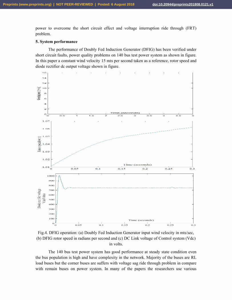
The performance of Doubly Fed Induction Generator (DFIG) has been verified under short circuit faults, power quality problems on 140 bus test power system as shown in figure. In this paper a constant wind velocity 15 mts per second taken as a reference, rotor speed and diode rectifier dc output voltage shown in figure.
Fig.4. DFIG operation: (a) Doubly Fed Induction Generator input wind velocity in mts/sec, (b) DFIG rotor speed in radians per second and (c) DC Link voltage of Control system (Vdc)
in volts.
The 140 bus test power system has good performance at steady state condition even the bus population is high and have complexity in the network. Majority of the buses are RL load buses but the corner buses are suffers with voltage sag ride through problem in compare with remain buses on power system. In many of the papers the researchers use various
Preprints (www.preprints.org) | NOT PEER-REVIEWED | Posted: 6 August 2018 doi:10.20944/preprints201808.0121.v1
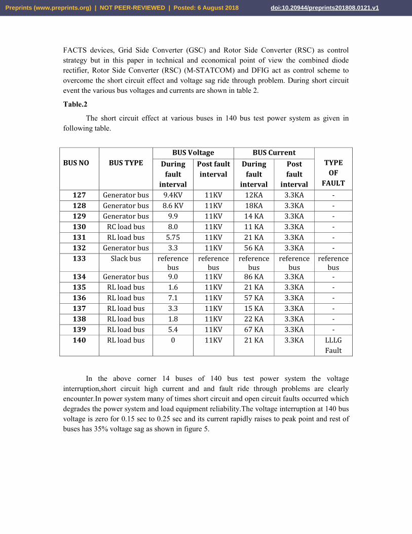
FACTS devices, Grid Side Converter (GSC) and Rotor Side Converter (RSC) as control strategy but in this paper in technical and economical point of view the combined diode rectifier, Rotor Side Converter (RSC) (M-STATCOM) and DFIG act as control scheme to overcome the short circuit effect and voltage sag ride through problem. During short circuit event the various bus voltages and currents are shown in table 2.
Table.2
The short circuit effect at various buses in 140 bus test power system as given in following table.
BUS NO
BUS TYPE
BUS Voltage BUS Current TYPE
OF FAULT
During fault
interval
Post fault interval
During fault
interval
Post fault
interval 127 Generator bus 9.4KV 11KV 12KA 3.3KA - 128 Generator bus 8.6 KV 11KV 18KA 3.3KA - 129 Generator bus 9.9 11KV 14 KA 3.3KA - 130 RC load bus 8.0 11KV 11 KA 3.3KA - 131 RL load bus 5.75 11KV 21 KA 3.3KA - 132 Generator bus 3.3 11KV 56 KA 3.3KA - 133 Slack bus reference
bus reference
bus reference
bus reference
bus reference
bus 134 Generator bus 9.0 11KV 86 KA 3.3KA - 135 RL load bus 1.6 11KV 21 KA 3.3KA - 136 RL load bus 7.1 11KV 57 KA 3.3KA - 137 RL load bus 3.3 11KV 15 KA 3.3KA - 138 RL load bus 1.8 11KV 22 KA 3.3KA - 139 RL load bus 5.4 11KV 67 KA 3.3KA - 140 RL load bus 0 11KV 21 KA 3.3KA LLLG
Fault
In the above corner 14 buses of 140 bus test power system the voltage interruption,short circuit high current and and fault ride through problems are clearly encounter.In power system many of times short circuit and open circuit faults occurred which degrades the power system and load equipment reliability.The voltage interruption at 140 bus voltage is zero for 0.15 sec to 0.25 sec and its current rapidly raises to peak point and rest of buses has 35% voltage sag as shown in figure 5.
Preprints (www.preprints.org) | NOT PEER-REVIEWED | Posted: 6 August 2018 doi:10.20944/preprints201808.0121.v1
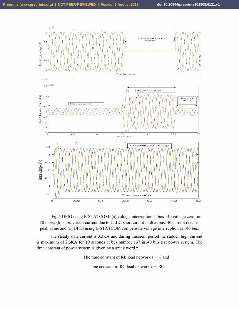
Fig.5.DFIG using E-STATCOM: (a) voltage interruption at bus 140 voltage zero for 10 msec, (b) short circuit current due to LLLG short circuit fault at bus140 current reaches peak value and (c) DFIG using E-STATCOM compensate voltage interruption at 140 bus.
The steady state current is 3.3KA and during transient period the sudden high current is maximum of 2.3KA for 10 seconds at bus number 137 in140 bus test power system. The time constant of power system is given by a greek word τ.
The time constant of RL load network τ = and
Time constant of RC load network τ = RC
Preprints (www.preprints.org) | NOT PEER-REVIEWED | Posted: 6 August 2018 doi:10.20944/preprints201808.0121.v1

The short circuit current is high at initial interval from 0.15 seconds onwards exponentially decreases and finally reaches stead state condition at 0.25 seconds as shown in figure
The short circuit high inrush current leads short duration over current problem recorded on 140 bus test power system results the reliability of power system and load equipment reduces and also cause to damage the customer equipment. During transient period, the power system LLLG fault effect on rest of buses reduced by proper power system protection through relay and three phase circuit breaker operation. Short circuit DFIG and E-STATCOM manages the bus voltage during transient period as shown in figure 5.
6. Conclusion The proposed E-STATCOM is a combine of diode rectifier and Rotor Side Converter
(RSC) to overcome the short circuit effect and FRT capability improvement at corner buses in 140 bus test power system. Shunt compensation scheme using DFIG+E-STATCOM is effective and proven as one good reactive power management scheme for voltage and power control. The operation of E-STATCOM with DFIG and its performance is better suit for improving power quality at 140 bus industrial grid test power system as per grid code standards. The tested and combine E-STATCOM + DFIG controller has many rewards like ease with restricted controller complexity prove to provide voltage interruption control, during fault, fault ride through current control and required demand reactive power support. This simulation results performed and used DFIG based wind turbine connected to electrical grid show better performance for short circuit fault effect, improving the FRT capability and power quality in rest of buses in 140 bus test power system.
References 1. Hortensia Amaris, Monica Alonso 2575–2586- Elsevier- Coordinated reactive power
management in power networks with wind turbines and FACTS devices. Energy Conversion and Management 52 (2011)
2. W. Qiao and R. G. Harley, “Grid connection requirements and solutions for DFIG wind turbines,” in Proc. IEEE Energy 2030 Conf. (ENERGY’08), Nov. 17–18, 2008, pp. 1–8.
3. X. P. Zhang, C. Rehtanz, and B. Pal, "Flexible AC Transmission Systems Modeling and Control," Germany: Springer-Verlag Berlin Heidelberg, pp. 1, 2, 15–18, 22, 2006.
4. K.V.Ramana Reddy, N. Ramesh Babu, P. Sanjeevikumar,.: “A Review on Grid Codes and Reactive Power Management in Power Grids with WECS” Advances in Smart Grid and Renewable Energy- Lecture Notes in Electrical Engineering - Springer, Singapore. (2018); 525-539.
5. K.V.Ramana Reddy, N. Ramesh Babu, “Enhancement of Power System Performance with svc- DFIG In 140 – bus system”. International Conference on Innovations in Power and Advanced Computing Technologies (i-PACT'17), at Vellore, India, 2017, pp. 1-5.
6. Abouzar Samimi, Mehdi Nikzad and Pierluigi Siano “Scenario-based stochastic framework for coupled active and reactive power market in smart distribution systems with demand response programs” Elsevier 6 march 2017.
Preprints (www.preprints.org) | NOT PEER-REVIEWED | Posted: 6 August 2018 doi:10.20944/preprints201808.0121.v1

7. A.RiniAnnJerin , PalanisamyKaliannan and UmashankarSubramaniam; “Improved fault ride through capability of DFIG based wind turbines using synchronous reference frame control based dynamic voltage restorer” Elsevier 6 july 2017.
8. A.Rini ann jerin amalorpavaraj, palanisamy kaliannan, sanjeevikumar padmanaban, umashankar subramaniam, and vigna k. ramachandaramurthy.“Improved Fault Ride Through Capability in DFIG Based Wind Turbines Using Dynamic Voltage Restorer With Combined Feed-Forward and Feed-Back Control” IEEE Access 25 october 2017.
9. Ramji Tiwari, N. Ramesh Babu, S. Padmanaban, L. Martirano and P. Siano, "Coordinated DTCand VOC control for PMSG based grid connected wind energy conversion system," 2017IEEE International Conference on Environment and Electrical Engineering and 2017 IEEEIndustrial and Commercial Power Systems Europe (EEEIC / I&CPS Europe), Milan, 2017.
10. Ramji Tiwari, Saravanan S, Ramesh Babu N, G. Kumar and V. Siwach, "Design anddevelopment of a high step-up DC-DC Converter for non-conventional energy applications,"2016 Biennial International Conference on Power and Energy Systems: Towards Sustainable Energy (PESTSE), Bangalore, 2016, pp. 1-4.
11. Ramji Tiwari, N. Ramesh Babu, "Recent developments of control strategies for windenergy conversion system." Renewable and Sustainable Energy Reviews. (2016); 66: 268-85.
12. Barakati, S.M.; Kazerani, M.; Aplevich, J.D. Maximum power tracking control for a wind turbine system including a matrix converter. IEEE Trans. Energy Convers. 2009, 24, 705–713.
13. Nasiri, M.; Milimonfared, J.; Fathi, S.H. Modeling, analysis and comparison of TSR and OTC methods for MPPT and power smoothing in permanent magnet synchronous generator-based wind turbines Energy Convers. Manag. 2014, 86, 892–900.
14. Babu, N.R.; Arulmozhivarman P. ‘Wind energy conversion systems-a technical review’. J. Eng. Sci. Technol.2013, 8, 493–507.
15. Alizadeh, M.; Kojori, S.S. Augmenting effectiveness of control loops of a PMSG (permanent magnet synchronous generator) based wind energy conversion system by a virtually adaptive PI (proportional integral) controller. Energy 2015, 91, 610–629.
16. Dalala, Z.M.; Zahid, Z.U.; Yu, W.; Cho, Y.; Lai, J. Design and analysis of an MPPT technique for small-scale wind energy conversion systems. IEEE Trans. Energy Convers. 2013, 28, 756–767.
17. Kumar, D.; Chatterjee, K. Design and analysis of artificial bee-colony-based MPPT algorithm for DFIG-based wind energy conversion systems. Int. J. Green Energy 2017, 14, 416–429.
18. J. Morren and S. W. H. D. Haan, ``Ridethrough of wind turbines with doubly-fed induction generator during a voltage dip,'' IEEE Trans. Energy Convers., vol. 20, no. 2, pp. 435_441, Jun. 2005.
19. M. Molinas, J. A. Suul, and T. Undeland, ``Low voltage ride through of wind farms with cage generators: STATCOM versus SVC,'' IEEE Trans Power Electron., vol. 23, no. 3, pp. 1104_1117, May 2008.
20. A. Kirakosyan, M. S. El Moursi, P. Kanjiya, and V. Khadkikar,``A nine switch converter-based fault ride through topology for wind turbine applications,'' IEEE Trans. Power Del., vol. 31, no. 4, pp. 1757_1766, Aug. 2016.
Preprints (www.preprints.org) | NOT PEER-REVIEWED | Posted: 6 August 2018 doi:10.20944/preprints201808.0121.v1