Embed Size (px)
Citation preview
Yu Dai i dr. Trodimenzionalno spregnuta dinamička analiza sustava iskapanja u dubokom oceanu
Tehnički vjesnik 23, 4(2016), 1037-1045 1037
ISSN 1330-3651 (Print), ISSN 1848-6339 (Online) DOI: 10.17559/TV-20150314135940
THREE-DIMENSIONAL COUPLED DYNAMIC ANALYSIS OF DEEP OCEAN MINING SYSTEM Yu Dai, He Liu, Tao Zhang, Shaojun Liu, Yan Li
Original scientific paper A new three-dimensional coupled dynamic model of the deep ocean mining system is developed. The seafloor tracked miner is built as a 3D single-body vehicle model with mesh element track-terrain interaction mechanics model, which not only can realize the fast dynamic simulation in contrast to traditional 3D multi-body model, but also can allow the loading of the seafloor sediment special terramechanics model. The mining pipeline is built as a 3D multi-body discrete element model that is divided into rigid elements linked by flexible connectors, also can realize the fast dynamic simulation for such long pipeline. New integrated mining operation modes for the total system are proposed and simulated, which show that during the whole operation processes, the synchronized stable motion of the total system can be kept well. The dynamic simulation analysis in the paper can provide important theoretical basis and technical reference for structure design, performance evaluation and operation control of the practical deep ocean mining system. Keywords: deep ocean mining system; dynamic simulation; mesh element mechanics model; multi-body discrete element model; 3D coupled dynamic model Trodimenzionalno spregnuta dinamička analiza sustava iskapanja u dubokom oceanu
Izvorni znanstveni članak Razvijen je novi trodimenzionalno spregnuti dinamički model sustava za rudarenje u dubokom oceanu. Kopač koji se vuče po dnu napravljen je kao 3D model kompaktnog vozila s mehaničkim modelom gusjeničara s elementima u zahvatu, s kojim ne samo da se može ostvariti brza dinamička simulacija nasuprot tradicionalnom 3D modelu sastavljenom od više dijelova, već se može također omogućiti nošenje specijalnog terramehaničkog modela za talog s morskog dna. Cjevovod za kopanje izrađen je kao 3D model diskretnih elemenata s više dijelova koji je podijeljen u krute elemente povezane fleksibilnim konektorima, i može također ostvariti brzu dinamičku simulaciju za tako dugačak cjevovod. Predloženi su i simulirani novi integrirani načini iskapanja za čitav sustav koji pokazuju da se kroz cijeli postupak može dobro održati stabilno sinhronizirano djelovanje čitavog sustava. Dinamička simulacijska analiza data u radu može pružiti važnu teoretsku bazu i tehničku referencu za dizajn konstrukcije, ocjenu djelovanja i kontrolu rada praktičnog sustava iskapanja u dubokom oceanu.
Ključne riječi: dinamička simulacija; mehanički model s elementima u zahvatu; model diskretnih elemenata s više dijelova; sustav za iskapanje u dubokom oceanu; 3D spregnuti dinamički model; 1 Introduction
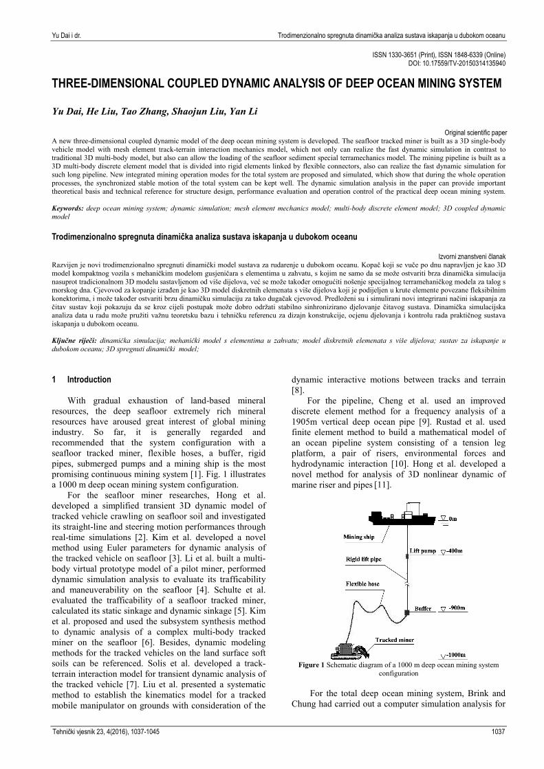
With gradual exhaustion of land-based mineral resources, the deep seafloor extremely rich mineral resources have aroused great interest of global mining industry. So far, it is generally regarded and recommended that the system configuration with a seafloor tracked miner, flexible hoses, a buffer, rigid pipes, submerged pumps and a mining ship is the most promising continuous mining system [1]. Fig. 1 illustrates a 1000 m deep ocean mining system configuration.
For the seafloor miner researches, Hong et al. developed a simplified transient 3D dynamic model of tracked vehicle crawling on seafloor soil and investigated its straight-line and steering motion performances through real-time simulations [2]. Kim et al. developed a novel method using Euler parameters for dynamic analysis of the tracked vehicle on seafloor [3]. Li et al. built a multi-body virtual prototype model of a pilot miner, performed dynamic simulation analysis to evaluate its trafficability and maneuverability on the seafloor [4]. Schulte et al. evaluated the trafficability of a seafloor tracked miner, calculated its static sinkage and dynamic sinkage [5]. Kim et al. proposed and used the subsystem synthesis method to dynamic analysis of a complex multi-body tracked miner on the seafloor [6]. Besides, dynamic modeling methods for the tracked vehicles on the land surface soft soils can be referenced. Solis et al. developed a track-terrain interaction model for transient dynamic analysis of the tracked vehicle [7]. Liu et al. presented a systematic method to establish the kinematics model for a tracked mobile manipulator on grounds with consideration of the
dynamic interactive motions between tracks and terrain [8].
For the pipeline, Cheng et al. used an improved discrete element method for a frequency analysis of a 1905m vertical deep ocean pipe [9]. Rustad et al. used finite element method to build a mathematical model of an ocean pipeline system consisting of a tension leg platform, a pair of risers, environmental forces and hydrodynamic interaction [10]. Hong et al. developed a novel method for analysis of 3D nonlinear dynamic of marine riser and pipes [11].
Figure 1 Schematic diagram of a 1000 m deep ocean mining system
configuration
For the total deep ocean mining system, Brink and Chung had carried out a computer simulation analysis for
Three-dimensional coupled dynamic analysis of deep ocean mining system Yu Dai et al.
1038 Technical Gazette 23, 4(2016), 1037-1045
dynamic positioning control of a large ocean mining ship-pipe system [12], and further proposed the research subject on how to perform the motion and positioning control of the total deep ocean system [13]. Hong et al. performed analysis on the coupled dynamics of the tracked vehicle and flexible riser [14].
However, it still remains a crucial problem to be further resolved, that is how to obtain and investigate the complex dynamic characteristics of the integrated operation processes of the total deep ocean mining system, so as to evaluate its design scheme, continuous operation performance and propose optimal mining operation modes, since it is very difficult to perform in-situ tests and impossible to establish a similar laboratory experimental system. The dynamic simulation is undoubtedly an effective way. Reliable and efficient dynamic models for subsystems and then coupled for the total system will be developed in the paper. 2 3D dynamic model of seafloor tracked miner 2.1 Single-body vehicle model with mesh element track-
terrain interaction mechanics model
In contrast to traditional 3D multi-body dynamic model of tracked vehicle, a 3D single-body dynamic model is developed for the following considerations. Firstly, all commercial codes for multi-body dynamic simulation of tracked vehicle only provide one type of soft soil mechanics model to represent land surface soft soil types, but it is definitely unsuitable for exhibiting the special mechanics of the seafloor extremely cohesive soft soil. Secondly, the multi-body dynamic model has a large number of DOFs and needs extremely long time for numerical simulation computation. Finally, it is reasonable to regard the miner as a single-body model of the total system’s multi-body model, and most attention for the miner in the total system is given to its overall dynamic behavior rather than its internal detailed dynamic interaction characteristics.
Figure 2 Single-body model structure of tracked vehicle
Fig. 2 illustrates the 3D single-body model structure
of the tracked vehicle, l, b and h are the total length, width and height of the vehicle, l1 is the track-terrain contact length, d is the track width, b1 is the centerline distance of the tracks, l2, b2 and h2 represent the mass center location of the vehicle.
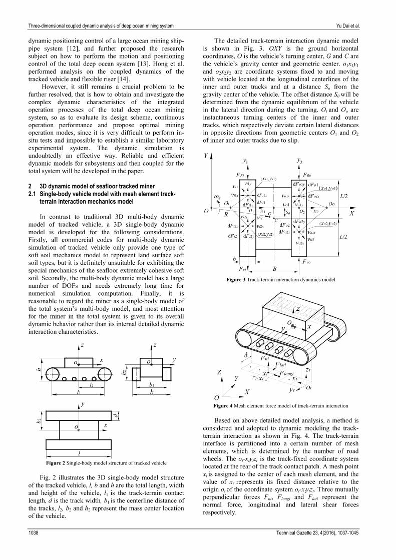
The detailed track-terrain interaction dynamic model is shown in Fig. 3. OXY is the ground horizontal coordinates, O is the vehicle’s turning center, G and C are the vehicle’s gravity center and geometric center. o1x1y1 and o2x2y2 are coordinate systems fixed to and moving with vehicle located at the longitudinal centerlines of the inner and outer tracks and at a distance So from the gravity center of the vehicle. The offset distance S0 will be determined from the dynamic equilibrium of the vehicle in the lateral direction during the turning. Oi and Oo are instantaneous turning centers of the inner and outer tracks, which respectively deviate certain lateral distances in opposite directions from geometric centers O1 and O2 of inner and outer tracks due to slip.
Figure 3 Track-terrain interaction dynamics model
xy
z
d
O
yt
△xiZ
Y
OX
Flongi
FlatiFni
xi xt
zt
Ot
Figure 4 Mesh element force model of track-terrain interaction
Based on above detailed model analysis, a method is
considered and adopted to dynamic modeling the track-terrain interaction as shown in Fig. 4. The track-terrain interface is partitioned into a certain number of mesh elements, which is determined by the number of road wheels. The ot-xtytzt is the track-fixed coordinate system located at the rear of the track contact patch. A mesh point xi is assigned to the center of each mesh element, and the value of xi represents its fixed distance relative to the origin ot of the coordinate system ot-xtytzt. Three mutually perpendicular forces Fni, Flongi and Flati represent the normal force, longitudinal and lateral shear forces respectively.
Yu Dai i dr. Trodimenzionalno spregnuta dinamička analiza sustava iskapanja u dubokom oceanu
Tehnički vjesnik 23, 4(2016), 1037-1045 1039
The normal force Fni is computed by multiplying the normal pressure pxi acting on the point xi by the area of each mesh element:
( ) ( )n i x iii
F x p x d= ⋅ ∆ ⋅ (1)
To compute the shear forces Flongi and Flati, the shear
displacements developed along the track-terrain interface should be determined firstly. For the mesh element model, the longitudinal shear displacement jxi needs to be computed at each mesh point xi as follow and applied to the whole surface of the mesh element:
( )ii
x ji xi s s
xr vs s xj v t
rω
ω= ⋅ = − ⋅ (2)
where vjxi is the longitudinal slip velocity of mesh point xi, vxi is the actual velocity of the point, rs and ωs are the radius and angular velocity of the sprocket.
The longitudinal shear force Flongi acting on each mesh point xi is computed by multiplying the shear stress by the area of each mesh element:
( ) ( ) ( )sgni x x ilong ii iF x j x dτ= ⋅ ⋅ ∆ ⋅ (3)
where 'sgn' is the signum function, τxi is the longitudinal shear stress acting on the mesh point xi.
The lateral shear displacement at each mesh point xi can be computed as:
yi
yj ii yi s s
xj v t v
r ω
′= ⋅ = ⋅ (4)
where vjyi is the lateral slip velocity of the mesh point xi, vyi is the lateral velocity, vjyi and vyi are the same for lateral motion.
The lateral shear force Flati acting on each mesh point xi is computed as follow and in the opposite direction to the lateral shear displacement:
( ) ( ) ( )sgni y y ilat i iiF x j x dτ= − ⋅ ⋅ ∆ ⋅ (5)
where τyi is the lateral shear stress acting on the mesh point xi.
2.2 Laboratory experimental validations
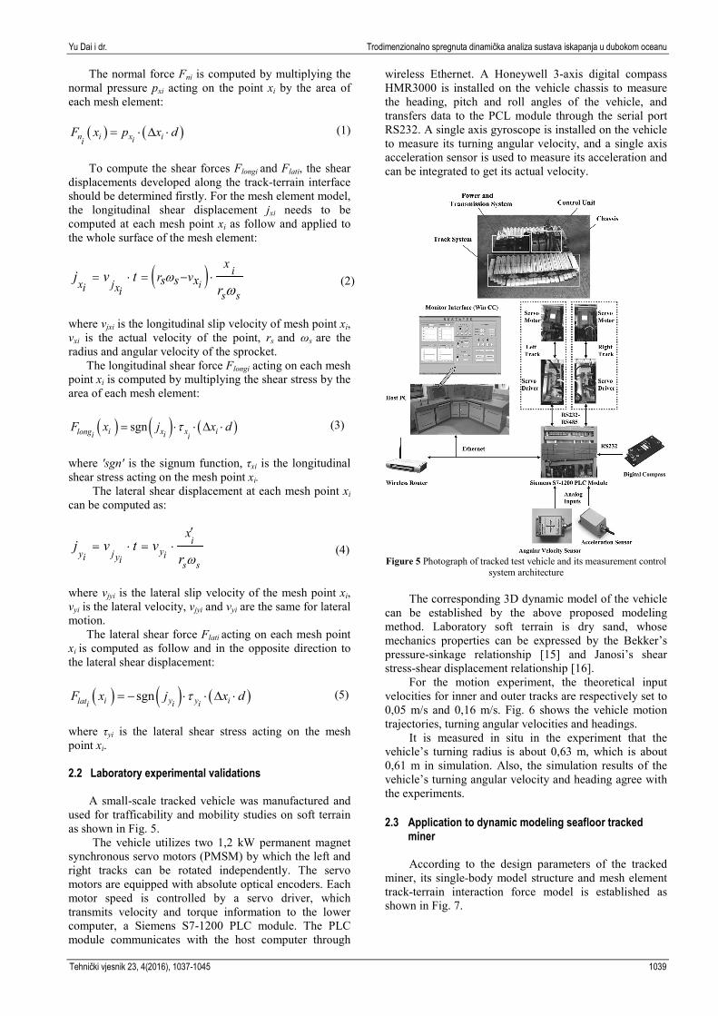
A small-scale tracked vehicle was manufactured and used for trafficability and mobility studies on soft terrain as shown in Fig. 5.
The vehicle utilizes two 1,2 kW permanent magnet synchronous servo motors (PMSM) by which the left and right tracks can be rotated independently. The servo motors are equipped with absolute optical encoders. Each motor speed is controlled by a servo driver, which transmits velocity and torque information to the lower computer, a Siemens S7-1200 PLC module. The PLC module communicates with the host computer through
wireless Ethernet. A Honeywell 3-axis digital compass HMR3000 is installed on the vehicle chassis to measure the heading, pitch and roll angles of the vehicle, and transfers data to the PCL module through the serial port RS232. A single axis gyroscope is installed on the vehicle to measure its turning angular velocity, and a single axis acceleration sensor is used to measure its acceleration and can be integrated to get its actual velocity.
Figure 5 Photograph of tracked test vehicle and its measurement control
system architecture The corresponding 3D dynamic model of the vehicle
can be established by the above proposed modeling method. Laboratory soft terrain is dry sand, whose mechanics properties can be expressed by the Bekker’s pressure-sinkage relationship [15] and Janosi’s shear stress-shear displacement relationship [16].
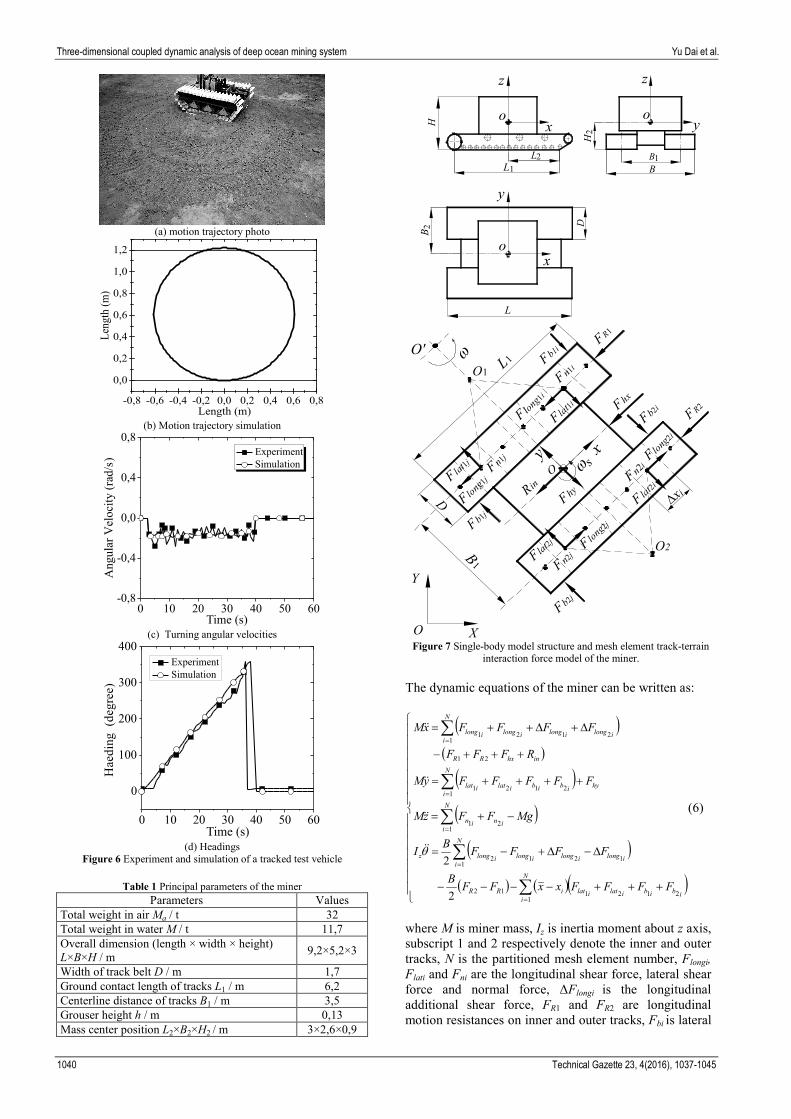
For the motion experiment, the theoretical input velocities for inner and outer tracks are respectively set to 0,05 m/s and 0,16 m/s. Fig. 6 shows the vehicle motion trajectories, turning angular velocities and headings.
It is measured in situ in the experiment that the vehicle’s turning radius is about 0,63 m, which is about 0,61 m in simulation. Also, the simulation results of the vehicle’s turning angular velocity and heading agree with the experiments.
2.3 Application to dynamic modeling seafloor tracked
miner
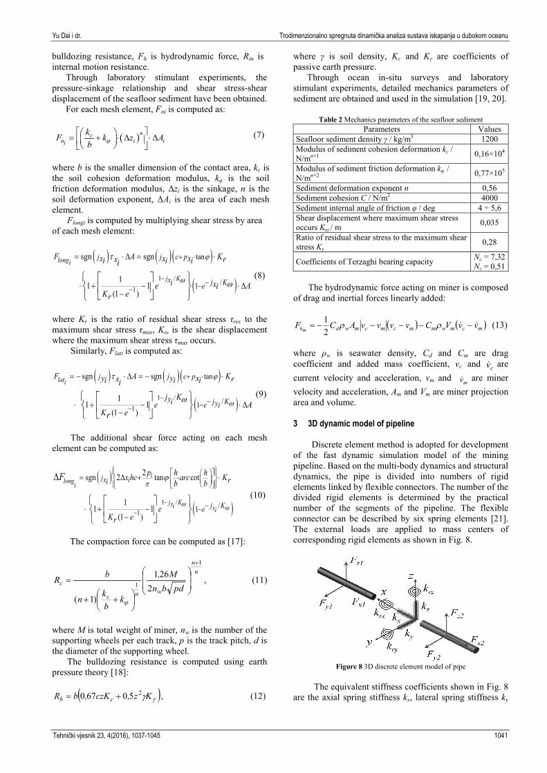
According to the design parameters of the tracked miner, its single-body model structure and mesh element track-terrain interaction force model is established as shown in Fig. 7.
Three-dimensional coupled dynamic analysis of deep ocean mining system Yu Dai et al.
1040 Technical Gazette 23, 4(2016), 1037-1045
(a) motion trajectory photo
(b) Motion trajectory simulation
(c) Turning angular velocities
(d) Headings
Figure 6 Experiment and simulation of a tracked test vehicle
Table 1 Principal parameters of the miner Parameters Values
Total weight in air Ma / t 32 Total weight in water M / t 11,7 Overall dimension (length × width × height) L×B×H / m 9,2×5,2×3
Width of track belt D / m 1,7 Ground contact length of tracks L1 / m 6,2 Centerline distance of tracks B1 / m 3,5 Grouser height h / m 0,13 Mass center position L2×B2×H2 / m 3×2,6×0,9
Figure 7 Single-body model structure and mesh element track-terrain
interaction force model of the miner.
The dynamic equations of the miner can be written as:
( )( )
( )( )
( )
( ) ( )( )
+++−−−−
∆−∆+−=
−+=
++++=
+++−
∆+∆++=
∑
∑
∑
∑
∑
=
=
=
=
=
N
iibibilatilatiRR
N
iilongilongilongilongz
N
iinin
N
ihyibibilatilat
inhxRR
N
iilongilongilongilong
FFFFxxFFB
FFFFBI
MgFFzM
FFFFFyM
RFFF
FFFFxM
1212112
11212
121
12121
21
12121
2
2θ
(6)
where M is miner mass, Iz is inertia moment about z axis, subscript 1 and 2 respectively denote the inner and outer tracks, N is the partitioned mesh element number, Flongi, Flati and Fni are the longitudinal shear force, lateral shear force and normal force, ΔFlongi is the longitudinal additional shear force, FR1 and FR2 are longitudinal motion resistances on inner and outer tracks, Fbi is lateral
Yu Dai i dr. Trodimenzionalno spregnuta dinamička analiza sustava iskapanja u dubokom oceanu
Tehnički vjesnik 23, 4(2016), 1037-1045 1041
bulldozing resistance, Fh is hydrodynamic force, Rin is internal motion resistance.
Through laboratory stimulant experiments, the pressure-sinkage relationship and shear stress-shear displacement of the seafloor sediment have been obtained.
For each mesh element, Fni is computed as:
( )ncn i ii
kF k z Ab ϕ
= + ⋅ ∆ ⋅∆ (7)
where b is the smaller dimension of the contact area, kc is the soil cohesion deformation modulus, kφ is the soil friction deformation modulus, Δzi is the sinkage, n is the soil deformation exponent, ΔAi is the area of each mesh element.
Flongi is computed by multiplying shear stress by area of each mesh element:
( ) ( ) ( )
( )1 /1
tan
/1
sgn sgn
11 1
(1 )
longi
j K
j j c p
x j Ki e
F A Kx x xx ri i ii
xe AiK er
ϕ
ω
τ
ω−
−
+ ⋅
−−
= ⋅ ∆ = ⋅
⋅ + − ⋅ ∆−
(8)
where Kr is the ratio of residual shear stress τres to the maximum shear stress τmax, Kω is the shear displacement where the maximum shear stress τmax occurs.
Similarly, Flati is computed as:
( ) ( ) ( )
( )1 /1
tan
/1
sgn sgn
11 1
(1 )
latij j c p
y j Ki ye i
F A Ky y xx ri i ii
j Ke A
K er
ϕ
ω
τ
ω−
−
+ ⋅
−−
= − ⋅ ∆ = − ⋅
⋅ + − ⋅ ∆−
(9)
The additional shear force acting on each mesh
element can be computed as:
( )
( )1 /1
/1
2sgn 2 tan cot
11 1
(1 )
iilongi
j Kxi xi
jxi
j Ke
p h hx hc arc Krb b
eK er
F
ω ω
pϕ
−−
⋅
−−
= ∆ + ⋅ ⋅
⋅ + −−
∆
(10)
The compaction force can be computed as [17]:
,2
261
)1(
1
1
nn
wnc
cpdbn
M,
kbkn
bR
+
++
=
ϕ
(11)
where M is total weight of miner, nw is the number of the supporting wheels per each track, p is the track pitch, d is the diameter of the supporting wheel.
The bulldozing resistance is computed using earth pressure theory [18]:
( ), 50670 2γγKz,czK,bR cb += (12)
where γ is soil density, Kc and Kγ are coefficients of passive earth pressure.
Through ocean in-situ surveys and laboratory stimulant experiments, detailed mechanics parameters of sediment are obtained and used in the simulation [19, 20].
Table 2 Mechanics parameters of the seafloor sediment Parameters Values
Seafloor sediment density γ / kg/m3 1200 Modulus of sediment cohesion deformation kc / N/mn+1 0,16×10⁴
Modulus of sediment friction deformation kφ / N/mn+2 0,77×10⁵
Sediment deformation exponent n 0,56 Sediment cohesion C / N/m2 4000 Sediment internal angle of friction φ / deg 4 ÷ 5,6 Shear displacement where maximum shear stress occurs Kω / m 0,035
Ratio of residual shear stress to the maximum shear stress Kr
0,28
Coefficients of Terzaghi bearing capacity Nc = 7,32 Nγ = 0,51
The hydrodynamic force acting on miner is composed
of drag and inertial forces linearly added:
( ) ( )mcmwmmcmcmw vvVCvvvvACF dmh −−−−−= ρρ21 (13)
where ρw is seawater density, Cd and Cm are drag coefficient and added mass coefficient, vc and cv are current velocity and acceleration, vm and mv are miner velocity and acceleration, Am and Vm are miner projection area and volume. 3 3D dynamic model of pipeline
Discrete element method is adopted for development
of the fast dynamic simulation model of the mining pipeline. Based on the multi-body dynamics and structural dynamics, the pipe is divided into numbers of rigid elements linked by flexible connectors. The number of the divided rigid elements is determined by the practical number of the segments of the pipeline. The flexible connector can be described by six spring elements [21]. The external loads are applied to mass centers of corresponding rigid elements as shown in Fig. 8.
Figure 8 3D discrete element model of pipe
The equivalent stiffness coefficients shown in Fig. 8
are the axial spring stiffness kx, lateral spring stiffness ky
Three-dimensional coupled dynamic analysis of deep ocean mining system Yu Dai et al.
1042 Technical Gazette 23, 4(2016), 1037-1045
and kz, torsional spring stiffness krx, and rotational spring stiffness kry and krz, which can be expressed as:
3 3/ ; 12 / ; 12 /
/ ; / ; /
k EA L k EI L k EI Lx y z z yk GI L k EI L k EI Lrx p ry y rz z
= = =
= = =
(14)
where E and G are Young modulus and shear modulus, A and L are cross-section area and length; Iy and Iz are second moments of area, Ip is polar moment of inertia.
The hydrodynamic force is calculated using Morison equation:
),(4
π)(21 2
pcwmpcpcwdh vvCdvv|vv|dCF −−−−−= ρρ (15)
where d is pipe outer diameter, vp and pv are pipe velocity and acceleration.
According to design scheme of pipeline subsystem, to keep its optimal spatial shape so as to ensure its transmission efficiency and safety, two buoyancy modules are installed on the flexible hose to make its spatial shape like a saddle as shown in Fig. 9. One buoyancy module is located at a distance of 134 m to the buffer providing the buoyancy force of about 4,2×10⁴ N, the other is located at a distance of 267 m to the buffer providing the buoyancy force of about 8,4×10⁴ N.
Figure 9 Buoyancy modulus configuration on flexible hose
4 Kinematics model of mining ship
Considering the mass of the mining ship and the
wave force acting on the ship are all much larger than the mass of the pipeline and the wave force acting on the pipeline respectively, it can be assumed that the motion of the mining ship is not influenced by the motion of the pipeline. Regarding the ship as a rigid body, its motions can be expressed as 6 DOFs as shown in Fig. 10.
However, it is generally regarded that the yaw motion has little influence on the ship and can be neglected, the roll and pitch motions can be compensated, the sway and surge motions can be conquered by dynamic positioning system, only the heave motion of the ship has the most influence on the pipeline.
The heave motion of the ship can be described as a harmonic motion equation with the same period as the ocean wave period.
, 2πsin
⋅⋅= t
Tzz hah (16)
where zh is the heave displacement of the ship, zha is the heave amplitude of the ship which is determined by the ship structure, ship dimension, wave height etc., T is the wave period.
Figure 10 6-DOFs motion of mining ship
According to design parameters of the mining ship,
and assuming that the ocean state is the 4 level (the surface wave height is 2,5 m, the wave period is 8 s), the ship speed is about 1kn, then the heave motion of the ship can be determined, which also can be changed and determined accordingly with different ocean surface state.
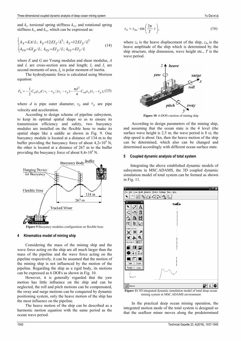
5 Coupled dynamic analysis of total system
Integrating the above established dynamic models of
subsystems in MSC.ADAMS, the 3D coupled dynamic simulation model of total system can be formed as shown in Fig. 11.
Figure 11 3D integrated dynamic simulation model of total deep ocean
mining system in MSC.ADAMS environment
In the practical deep ocean mining operation, the integrated motion mode of the total system is designed so that the seafloor miner moves along the predetermined
Yu Dai i dr. Trodimenzionalno spregnuta dinamička analiza sustava iskapanja u dubokom oceanu
Tehnički vjesnik 23, 4(2016), 1037-1045 1043
mining paths, while the ship tows the pipeline subsystem to follow the miner, which is referenced for the designs and dynamic simulation analysis of the mining operation modes of the total system in the paper.
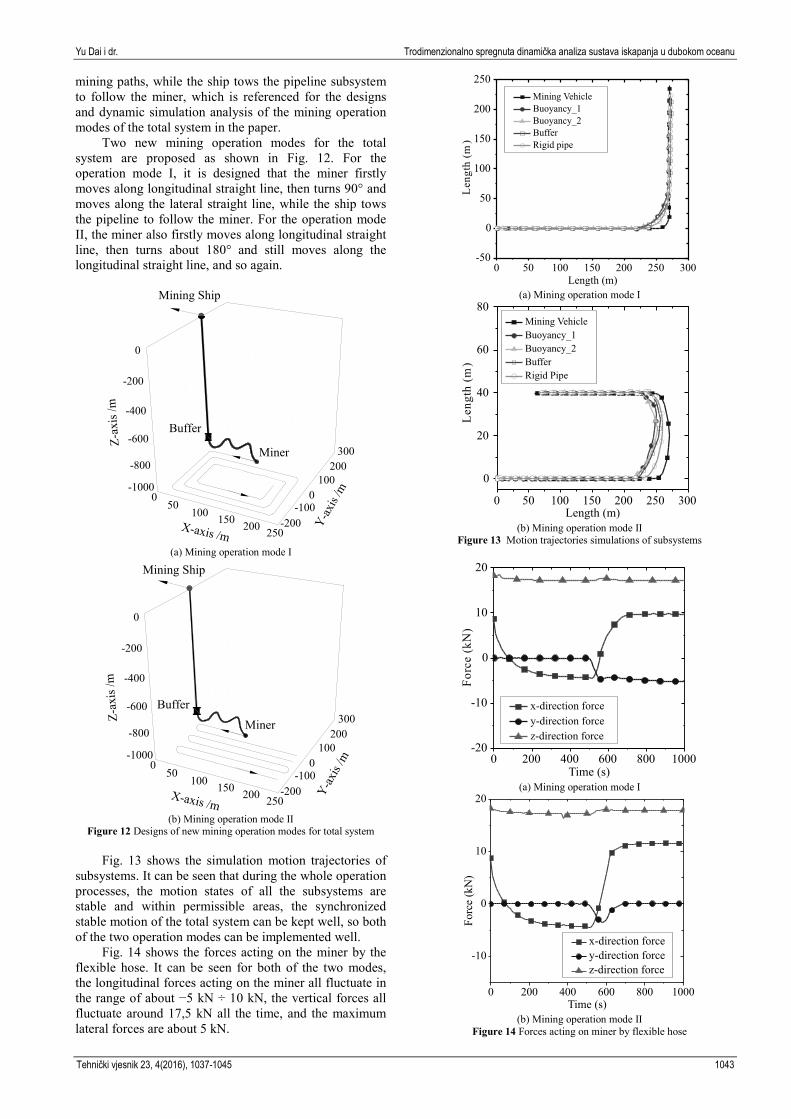
Two new mining operation modes for the total system are proposed as shown in Fig. 12. For the operation mode I, it is designed that the miner firstly moves along longitudinal straight line, then turns 90° and moves along the lateral straight line, while the ship tows the pipeline to follow the miner. For the operation mode II, the miner also firstly moves along longitudinal straight line, then turns about 180° and still moves along the longitudinal straight line, and so again.
X-axis /m
Y-ax
is /m
Z-ax
is /m
0
-200
-400
-600
-800
-100050
100 150 200 250
-1000
100200
300
0
-200
Mining Ship
Miner
Buffer
(a) Mining operation mode I
X-axis /m
Y-ax
is /m
Z-ax
is /m
0
-200
-400
-600
-800
-100050
100 150 200 250
-1000
100200
300
0
-200
Miner
Mining Ship
Buffer
(b) Mining operation mode II
Figure 12 Designs of new mining operation modes for total system
Fig. 13 shows the simulation motion trajectories of subsystems. It can be seen that during the whole operation processes, the motion states of all the subsystems are stable and within permissible areas, the synchronized stable motion of the total system can be kept well, so both of the two operation modes can be implemented well.
Fig. 14 shows the forces acting on the miner by the flexible hose. It can be seen for both of the two modes, the longitudinal forces acting on the miner all fluctuate in the range of about −5 kN ÷ 10 kN, the vertical forces all fluctuate around 17,5 kN all the time, and the maximum lateral forces are about 5 kN.
(a) Mining operation mode I
(b) Mining operation mode II
Figure 13 Motion trajectories simulations of subsystems
(a) Mining operation mode I
(b) Mining operation mode II
Figure 14 Forces acting on miner by flexible hose
Three-dimensional coupled dynamic analysis of deep ocean mining system Yu Dai et al.
1044 Technical Gazette 23, 4(2016), 1037-1045
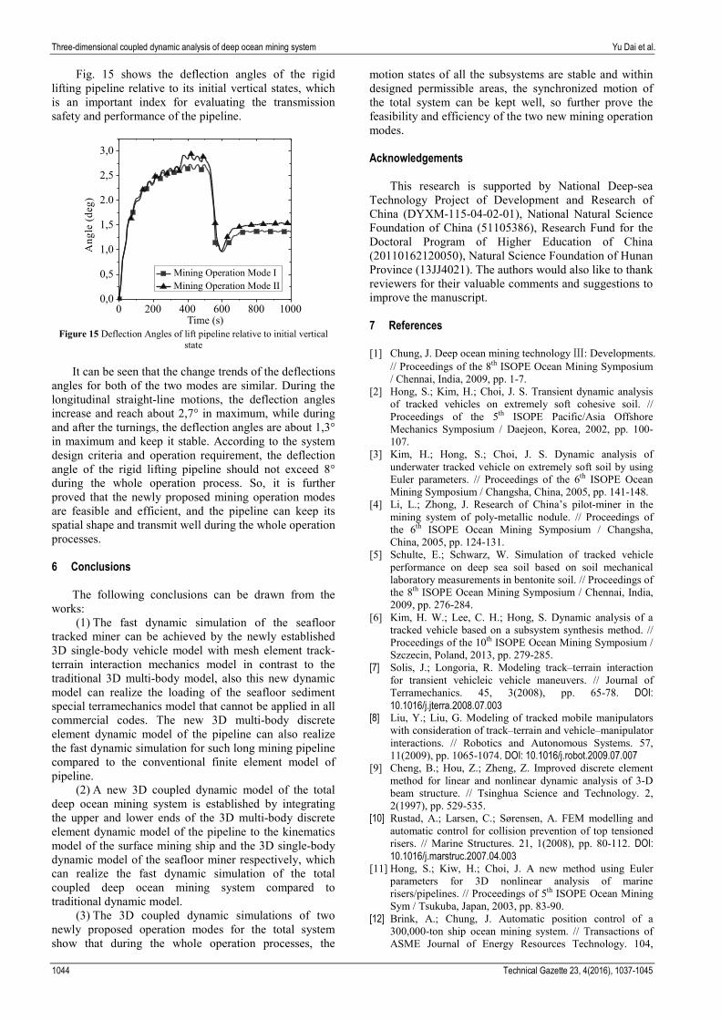
Fig. 15 shows the deflection angles of the rigid lifting pipeline relative to its initial vertical states, which is an important index for evaluating the transmission safety and performance of the pipeline.
Figure 15 Deflection Angles of lift pipeline relative to initial vertical
state
It can be seen that the change trends of the deflections angles for both of the two modes are similar. During the longitudinal straight-line motions, the deflection angles increase and reach about 2,7° in maximum, while during and after the turnings, the deflection angles are about 1,3° in maximum and keep it stable. According to the system design criteria and operation requirement, the deflection angle of the rigid lifting pipeline should not exceed 8° during the whole operation process. So, it is further proved that the newly proposed mining operation modes are feasible and efficient, and the pipeline can keep its spatial shape and transmit well during the whole operation processes. 6 Conclusions
The following conclusions can be drawn from the works:
(1) The fast dynamic simulation of the seafloor tracked miner can be achieved by the newly established 3D single-body vehicle model with mesh element track-terrain interaction mechanics model in contrast to the traditional 3D multi-body model, also this new dynamic model can realize the loading of the seafloor sediment special terramechanics model that cannot be applied in all commercial codes. The new 3D multi-body discrete element dynamic model of the pipeline can also realize the fast dynamic simulation for such long mining pipeline compared to the conventional finite element model of pipeline.
(2) A new 3D coupled dynamic model of the total deep ocean mining system is established by integrating the upper and lower ends of the 3D multi-body discrete element dynamic model of the pipeline to the kinematics model of the surface mining ship and the 3D single-body dynamic model of the seafloor miner respectively, which can realize the fast dynamic simulation of the total coupled deep ocean mining system compared to traditional dynamic model.
(3) The 3D coupled dynamic simulations of two newly proposed operation modes for the total system show that during the whole operation processes, the
motion states of all the subsystems are stable and within designed permissible areas, the synchronized motion of the total system can be kept well, so further prove the feasibility and efficiency of the two new mining operation modes.
Acknowledgements
This research is supported by National Deep-sea
Technology Project of Development and Research of China (DYXM-115-04-02-01), National Natural Science Foundation of China (51105386), Research Fund for the Doctoral Program of Higher Education of China (20110162120050), Natural Science Foundation of Hunan Province (13JJ4021). The authors would also like to thank reviewers for their valuable comments and suggestions to improve the manuscript. 7 References [1] Chung, J. Deep ocean mining technology Ⅲ: Developments.
// Proceedings of the 8th ISOPE Ocean Mining Symposium / Chennai, India, 2009, pp. 1-7.
[2] Hong, S.; Kim, H.; Choi, J. S. Transient dynamic analysis of tracked vehicles on extremely soft cohesive soil. // Proceedings of the 5th ISOPE Pacific/Asia Offshore Mechanics Symposium / Daejeon, Korea, 2002, pp. 100-107.
[3] Kim, H.; Hong, S.; Choi, J. S. Dynamic analysis of underwater tracked vehicle on extremely soft soil by using Euler parameters. // Proceedings of the 6th ISOPE Ocean Mining Symposium / Changsha, China, 2005, pp. 141-148.
[4] Li, L.; Zhong, J. Research of China’s pilot-miner in the mining system of poly-metallic nodule. // Proceedings of the 6th ISOPE Ocean Mining Symposium / Changsha, China, 2005, pp. 124-131.
[5] Schulte, E.; Schwarz, W. Simulation of tracked vehicle performance on deep sea soil based on soil mechanical laboratory measurements in bentonite soil. // Proceedings of the 8th ISOPE Ocean Mining Symposium / Chennai, India, 2009, pp. 276-284.
[6] Kim, H. W.; Lee, C. H.; Hong, S. Dynamic analysis of a tracked vehicle based on a subsystem synthesis method. // Proceedings of the 10th ISOPE Ocean Mining Symposium / Szczecin, Poland, 2013, pp. 279-285.
[7] Solis, J.; Longoria, R. Modeling track–terrain interaction for transient vehicleic vehicle maneuvers. // Journal of Terramechanics. 45, 3(2008), pp. 65-78. DOI: 10.1016/j.jterra.2008.07.003
[8] Liu, Y.; Liu, G. Modeling of tracked mobile manipulators with consideration of track–terrain and vehicle–manipulator interactions. // Robotics and Autonomous Systems. 57, 11(2009), pp. 1065-1074. DOI: 10.1016/j.robot.2009.07.007
[9] Cheng, B.; Hou, Z.; Zheng, Z. Improved discrete element method for linear and nonlinear dynamic analysis of 3-D beam structure. // Tsinghua Science and Technology. 2, 2(1997), pp. 529-535.
[10] Rustad, A.; Larsen, C.; Sørensen, A. FEM modelling and automatic control for collision prevention of top tensioned risers. // Marine Structures. 21, 1(2008), pp. 80-112. DOI: 10.1016/j.marstruc.2007.04.003
[11] Hong, S.; Kiw, H.; Choi, J. A new method using Euler parameters for 3D nonlinear analysis of marine risers/pipelines. // Proceedings of 5th ISOPE Ocean Mining Sym / Tsukuba, Japan, 2003, pp. 83-90.
[12] Brink, A.; Chung, J. Automatic position control of a 300,000-ton ship ocean mining system. // Transactions of ASME Journal of Energy Resources Technology. 104,
Yu Dai i dr. Trodimenzionalno spregnuta dinamička analiza sustava iskapanja u dubokom oceanu
Tehnički vjesnik 23, 4(2016), 1037-1045 1045
4(1982), pp. 285-293. DOI: 10.1115/1.3230417 [13] Chung, J. Motion and positioning control of deep-ocean
ship–riser–equipment system: deep-ocean test experiences for going deeper. // Proceedings of the 3rd International Deep-Ocean Technology Symposium / Beijing, China, 2009, pp. 90-97.
[14] Hong, S.; Kim, H. Coupled dynamic analysis of underwater tracked vehicle and long flexible pipe. // Proceedings of the 6th Ocean Mining Symposium / Changsha, China, 2005, pp. 132-140.
[15] Bekker, M. Introduction to terrain-vehicle systems. University of Michigan Press, Michigan, USA, 1969.
[16] Janosi, Z.; Hanamto, B. The analytical determination of drawbar pull as a function of slip for tracked vehicles in deformable soils. // International Conference of the International Society for Terrain-Vehicle Systems / Torino. Italy, 1961, pp. 707-736.
[17] Rowland, D. A review of vehicle design for soft-ground operation. // The 5th International Conference of the International Society for Terrain-Vehicle System / Detroit-Houghton, Michigan, USA, 1975, pp. 179-219.
[18] Wong, J. Y. Terramechanics and off-road vehicle engineering. Elsevier Science Publishers B. V., Amsterdam, the Netherlands, 2010.
[19] Song, L. Q. Geotechnical properties of oceanic polymetallic nodule sediments. // Acta Oceanologica Sinica. 21, 6(1999), pp. 47-54.
[20] Dai, Y.; Liu, S. J. Theoretical design and dynamic simulation of new mining paths of tracked miner on deep seafloor. // Journal of Central South University. 20, 4(2013), pp. 918-923. DOI: 10.1007/s11771-013-1566-z
[21] Li, Y.; Liu, S. J. Three-Dimensional DEM Model for Deep-Ocean Mining Pipe System. // Proceedings of the 6th ISOPE Ocean Mining Symposium / Changsha, China, 2005, pp. 88-93. Authors’ addresses Yu Dai, Associate Professor in ME and EE, (Corresponding author), College of Mechanical and Electrical Engineering, Central South University, Shenzhen Research Institute, Room A511, New Campus, Yuelu District, 410083 Changsha, China E-mail: [email protected] He Liu, Master in ME and EE College of Mechanical and Electrical Engineering, Central South University, Room B504, New Campus, Yuelu District, 410083 Changsha, P. R. China E-mail: [email protected] Tao Zhang, Master in ME and EE College of Mechanical and Electrical Engineering, Central South University, Room B504, New Campus, Yuelu District, 410083 Changsha, China E-mail: [email protected] Shaojun Liu, Professor in ME and EE College of Mechanical and Electrical Engineering, Central South University, Shenzhen Research Institute, Room A517, New Campus, Yuelu District, 410083 Changsha, China E-mail: [email protected] Yan Li, Associate Professor in ME and EE College of Mechanical and Electrical Engineering, Central South University, Shenzhen Research Institute, Room A516, New Campus, Yuelu District, 410083 Changsha, China E-mail: [email protected]