Embed Size (px)
Citation preview

Z-Star Protocol Standard
156659-1 11/16
Microsemi Corporate HeadquartersOne Enterprise, Aliso Viejo,CA 92656 USAWithin the USA: +1 (800) 713-4113 Outside the USA: +1 (949) 380-6100Fax: +1 (949) 215-4996Email: [email protected]
© 2016 Microsemi Corporation. All rights reserved. Microsemi and the Microsemi logo are trademarks of Microsemi Corporation. All other trademarks and service marks are the property of their respective owners.
Microsemi makes no warranty, representation, or guarantee regarding the information contained herein or the suitability of its products and services for any particular purpose, nor does Microsemi assume any liability whatsoever arising out of the application or use of any product or circuit. The products sold hereunder and any other products sold by Microsemi have been subject to limited testing and should not be used in conjunction with mission-critical equipment or applications. Any performance specifications are believed to be reliable but are not verified, and Buyer must conduct and complete all performance and other testing of the products, alone and together with, or installed in, any end-products. Buyer shall not rely on any data and performance specifications or parameters provided by Microsemi. It is the Buyer's responsibility to independently determine suitability of any products and to test and verify the same. The information provided by Microsemi hereunder is provided “as is, where is” and with all faults, and the entire risk associated with such information is entirely with the Buyer. Microsemi does not grant, explicitly or implicitly, to any party any patent rights, licenses, or any other IP rights, whether with regard to such information itself or anything described by such information. Information provided in this document is proprietary to Microsemi, and Microsemi reserves the right to make any changes to the information in this document or to any products and services at any time without notice.
About Microsemi
Microsemi Corporation (Nasdaq: MSCC) offers a comprehensive portfolio of semiconductor and system solutions for aerospace & defense, communications, data center and industrial markets. Products include high-performance and radiation-hardened analog mixed-signal integrated circuits, FPGAs, SoCs and ASICs; power management products; timing and synchronization devices and precise time solutions, setting the world's standard for time; voice processing devices; RF solutions; discrete components; enterprise storage and communication solutions, security technologies and scalable anti-tamper products; Ethernet solutions; Power-over-Ethernet ICs and midspans; as well as custom design capabilities and services. Microsemi is headquartered in Aliso Viejo, California, and has approximately 4,800 employees globally. Learn more at www.microsemi.com.
Contents
1 Revision History . . . . . . . . . . . . . . . . . . . . . . . . . . . . . . . . . . . . . . . . . . . . . . . . . . . . . 11.1 Revision 1 . . . . . . . . . . . . . . . . . . . . . . . . . . . . . . . . . . . . . . . . . . . . . . . . . . . . . . . . . . . . . . . . . . . . . . . . 1
2 Overview . . . . . . . . . . . . . . . . . . . . . . . . . . . . . . . . . . . . . . . . . . . . . . . . . . . . . . . . . . 22.1 Topology . . . . . . . . . . . . . . . . . . . . . . . . . . . . . . . . . . . . . . . . . . . . . . . . . . . . . . . . . . . . . . . . . . . . . . . . . 2
2.1.1 Star Configuration . . . . . . . . . . . . . . . . . . . . . . . . . . . . . . . . . . . . . . . . . . . . . . . . . . . . . . . . . . . 2
2.2 Supplemental Information . . . . . . . . . . . . . . . . . . . . . . . . . . . . . . . . . . . . . . . . . . . . . . . . . . . . . . . . . . . . 22.2.1 Applicable Documents . . . . . . . . . . . . . . . . . . . . . . . . . . . . . . . . . . . . . . . . . . . . . . . . . . . . . . . . 3
3 Frame Format . . . . . . . . . . . . . . . . . . . . . . . . . . . . . . . . . . . . . . . . . . . . . . . . . . . . . . 53.1 General Frame Format . . . . . . . . . . . . . . . . . . . . . . . . . . . . . . . . . . . . . . . . . . . . . . . . . . . . . . . . . . . . . . 5
3.1.1 Preamble . . . . . . . . . . . . . . . . . . . . . . . . . . . . . . . . . . . . . . . . . . . . . . . . . . . . . . . . . . . . . . . . . . 53.1.2 Frame Sync . . . . . . . . . . . . . . . . . . . . . . . . . . . . . . . . . . . . . . . . . . . . . . . . . . . . . . . . . . . . . . . . 53.1.3 PHY Header . . . . . . . . . . . . . . . . . . . . . . . . . . . . . . . . . . . . . . . . . . . . . . . . . . . . . . . . . . . . . . . 63.1.4 MAC Frame Header . . . . . . . . . . . . . . . . . . . . . . . . . . . . . . . . . . . . . . . . . . . . . . . . . . . . . . . . . 73.1.5 MAC Payload . . . . . . . . . . . . . . . . . . . . . . . . . . . . . . . . . . . . . . . . . . . . . . . . . . . . . . . . . . . . . . . 93.1.6 Frame Check Sequence (FCS) Field . . . . . . . . . . . . . . . . . . . . . . . . . . . . . . . . . . . . . . . . . . . 10
3.2 Data Frame Format . . . . . . . . . . . . . . . . . . . . . . . . . . . . . . . . . . . . . . . . . . . . . . . . . . . . . . . . . . . . . . . . 10
3.3 Acknowledgment Frames . . . . . . . . . . . . . . . . . . . . . . . . . . . . . . . . . . . . . . . . . . . . . . . . . . . . . . . . . . . 10
3.4 Beacon Frame Type . . . . . . . . . . . . . . . . . . . . . . . . . . . . . . . . . . . . . . . . . . . . . . . . . . . . . . . . . . . . . . . 11
3.5 Command Type Frames . . . . . . . . . . . . . . . . . . . . . . . . . . . . . . . . . . . . . . . . . . . . . . . . . . . . . . . . . . . . 123.5.1 Association Request Frame Time . . . . . . . . . . . . . . . . . . . . . . . . . . . . . . . . . . . . . . . . . . . . . . 123.5.2 Association Response Frame Type . . . . . . . . . . . . . . . . . . . . . . . . . . . . . . . . . . . . . . . . . . . . . 123.5.3 Disassociation Request Frame Type . . . . . . . . . . . . . . . . . . . . . . . . . . . . . . . . . . . . . . . . . . . . 143.5.4 Data Request Frame Type . . . . . . . . . . . . . . . . . . . . . . . . . . . . . . . . . . . . . . . . . . . . . . . . . . . 143.5.5 Beacon Request Frame Type . . . . . . . . . . . . . . . . . . . . . . . . . . . . . . . . . . . . . . . . . . . . . . . . . 15
3.6 Administration Type Frames . . . . . . . . . . . . . . . . . . . . . . . . . . . . . . . . . . . . . . . . . . . . . . . . . . . . . . . . . 153.6.1 Channel Table Request Frame Type . . . . . . . . . . . . . . . . . . . . . . . . . . . . . . . . . . . . . . . . . . . 153.6.2 Channel Table Frame Type . . . . . . . . . . . . . . . . . . . . . . . . . . . . . . . . . . . . . . . . . . . . . . . . . . . 153.6.3 Channel Change Command Frame Type . . . . . . . . . . . . . . . . . . . . . . . . . . . . . . . . . . . . . . . . 163.6.4 Link Quality Request Frame Type . . . . . . . . . . . . . . . . . . . . . . . . . . . . . . . . . . . . . . . . . . . . . . 163.6.5 Link Quality Data Frame Type . . . . . . . . . . . . . . . . . . . . . . . . . . . . . . . . . . . . . . . . . . . . . . . . . 17
3.7 Short Frame Format . . . . . . . . . . . . . . . . . . . . . . . . . . . . . . . . . . . . . . . . . . . . . . . . . . . . . . . . . . . . . . . . 173.7.1 Frame Format Field . . . . . . . . . . . . . . . . . . . . . . . . . . . . . . . . . . . . . . . . . . . . . . . . . . . . . . . . . 183.7.2 MAC Frame Length . . . . . . . . . . . . . . . . . . . . . . . . . . . . . . . . . . . . . . . . . . . . . . . . . . . . . . . . . 183.7.3 FCS Length . . . . . . . . . . . . . . . . . . . . . . . . . . . . . . . . . . . . . . . . . . . . . . . . . . . . . . . . . . . . . . . 183.7.4 Frame Type Field . . . . . . . . . . . . . . . . . . . . . . . . . . . . . . . . . . . . . . . . . . . . . . . . . . . . . . . . . . 183.7.5 Frame Subtype Field . . . . . . . . . . . . . . . . . . . . . . . . . . . . . . . . . . . . . . . . . . . . . . . . . . . . . . . . 183.7.6 Frame Sequence Number Field . . . . . . . . . . . . . . . . . . . . . . . . . . . . . . . . . . . . . . . . . . . . . . . 183.7.7 Acknowledgment Request (AR) . . . . . . . . . . . . . . . . . . . . . . . . . . . . . . . . . . . . . . . . . . . . . . . 193.7.8 Transmit Now (TN)— ACK Frame Only . . . . . . . . . . . . . . . . . . . . . . . . . . . . . . . . . . . . . . . . . . 193.7.9 Frame Pending (FP) . . . . . . . . . . . . . . . . . . . . . . . . . . . . . . . . . . . . . . . . . . . . . . . . . . . . . . . . 193.7.10 Security . . . . . . . . . . . . . . . . . . . . . . . . . . . . . . . . . . . . . . . . . . . . . . . . . . . . . . . . . . . . . . . . . . 193.7.11 Destination ID . . . . . . . . . . . . . . . . . . . . . . . . . . . . . . . . . . . . . . . . . . . . . . . . . . . . . . . . . . . . . 193.7.12 Source ID . . . . . . . . . . . . . . . . . . . . . . . . . . . . . . . . . . . . . . . . . . . . . . . . . . . . . . . . . . . . . . . . . 193.7.13 Network ID . . . . . . . . . . . . . . . . . . . . . . . . . . . . . . . . . . . . . . . . . . . . . . . . . . . . . . . . . . . . . . . . 193.7.14 MAC Payload . . . . . . . . . . . . . . . . . . . . . . . . . . . . . . . . . . . . . . . . . . . . . . . . . . . . . . . . . . . . . . 193.7.15 MAC Frame CRC FCS . . . . . . . . . . . . . . . . . . . . . . . . . . . . . . . . . . . . . . . . . . . . . . . . . . . . . . 193.7.16 Short Acknowledgment Frames . . . . . . . . . . . . . . . . . . . . . . . . . . . . . . . . . . . . . . . . . . . . . . . 19
4 Frame Processing . . . . . . . . . . . . . . . . . . . . . . . . . . . . . . . . . . . . . . . . . . . . . . . . . . 21
Z-Star Protocol Standard Revision 1 iii
4.1 Addressing . . . . . . . . . . . . . . . . . . . . . . . . . . . . . . . . . . . . . . . . . . . . . . . . . . . . . . . . . . . . . . . . . . . . . . . 214.1.1 Short Address Assignments . . . . . . . . . . . . . . . . . . . . . . . . . . . . . . . . . . . . . . . . . . . . . . . . . . 21
4.2 Superframe Formats . . . . . . . . . . . . . . . . . . . . . . . . . . . . . . . . . . . . . . . . . . . . . . . . . . . . . . . . . . . . . . . 21
4.3 Channel Access . . . . . . . . . . . . . . . . . . . . . . . . . . . . . . . . . . . . . . . . . . . . . . . . . . . . . . . . . . . . . . . . . . . 22
4.4 Frame Transaction Types . . . . . . . . . . . . . . . . . . . . . . . . . . . . . . . . . . . . . . . . . . . . . . . . . . . . . . . . . . . 224.4.1 Single Frame Transaction . . . . . . . . . . . . . . . . . . . . . . . . . . . . . . . . . . . . . . . . . . . . . . . . . . . . 224.4.2 Data-ACK Frame Transaction . . . . . . . . . . . . . . . . . . . . . . . . . . . . . . . . . . . . . . . . . . . . . . . . . 224.4.3 Data-ACK Frame Transaction with a Hub Data Transaction . . . . . . . . . . . . . . . . . . . . . . . . . . 224.4.4 Data Request Frame Transaction . . . . . . . . . . . . . . . . . . . . . . . . . . . . . . . . . . . . . . . . . . . . . . 22
4.5 Frame Reception . . . . . . . . . . . . . . . . . . . . . . . . . . . . . . . . . . . . . . . . . . . . . . . . . . . . . . . . . . . . . . . . . . 224.5.1 Frame Reception by the Hub . . . . . . . . . . . . . . . . . . . . . . . . . . . . . . . . . . . . . . . . . . . . . . . . . . 234.5.2 Frame Reception by a Node . . . . . . . . . . . . . . . . . . . . . . . . . . . . . . . . . . . . . . . . . . . . . . . . . . 23
4.6 Acknowledging a Frame . . . . . . . . . . . . . . . . . . . . . . . . . . . . . . . . . . . . . . . . . . . . . . . . . . . . . . . . . . . . 23
4.7 Starting a Network . . . . . . . . . . . . . . . . . . . . . . . . . . . . . . . . . . . . . . . . . . . . . . . . . . . . . . . . . . . . . . . . . 234.7.1 Channel List . . . . . . . . . . . . . . . . . . . . . . . . . . . . . . . . . . . . . . . . . . . . . . . . . . . . . . . . . . . . . . . 234.7.2 Channel Table . . . . . . . . . . . . . . . . . . . . . . . . . . . . . . . . . . . . . . . . . . . . . . . . . . . . . . . . . . . . . 24
5 Frame Transactions . . . . . . . . . . . . . . . . . . . . . . . . . . . . . . . . . . . . . . . . . . . . . . . . . 255.1 Beacon Request and Transmission . . . . . . . . . . . . . . . . . . . . . . . . . . . . . . . . . . . . . . . . . . . . . . . . . . . . 25
5.1.1 Network Scan (Discovery) . . . . . . . . . . . . . . . . . . . . . . . . . . . . . . . . . . . . . . . . . . . . . . . . . . . . 265.1.2 Beacon Request . . . . . . . . . . . . . . . . . . . . . . . . . . . . . . . . . . . . . . . . . . . . . . . . . . . . . . . . . . . 265.1.3 Beacon Transmission . . . . . . . . . . . . . . . . . . . . . . . . . . . . . . . . . . . . . . . . . . . . . . . . . . . . . . . 275.1.4 Beacon Reception . . . . . . . . . . . . . . . . . . . . . . . . . . . . . . . . . . . . . . . . . . . . . . . . . . . . . . . . . . 27
5.2 Association . . . . . . . . . . . . . . . . . . . . . . . . . . . . . . . . . . . . . . . . . . . . . . . . . . . . . . . . . . . . . . . . . . . . . . . 275.2.1 Association Request . . . . . . . . . . . . . . . . . . . . . . . . . . . . . . . . . . . . . . . . . . . . . . . . . . . . . . . . 275.2.2 Authentication (Pairing Authorization) . . . . . . . . . . . . . . . . . . . . . . . . . . . . . . . . . . . . . . . . . . . 275.2.3 Association Response . . . . . . . . . . . . . . . . . . . . . . . . . . . . . . . . . . . . . . . . . . . . . . . . . . . . . . . 285.2.4 Association Transaction Diagrams . . . . . . . . . . . . . . . . . . . . . . . . . . . . . . . . . . . . . . . . . . . . . 28
5.3 Disassociation . . . . . . . . . . . . . . . . . . . . . . . . . . . . . . . . . . . . . . . . . . . . . . . . . . . . . . . . . . . . . . . . . . . . 315.3.1 Disassociation Request from the Hub . . . . . . . . . . . . . . . . . . . . . . . . . . . . . . . . . . . . . . . . . . . 315.3.2 Disassociation Request from the Node (Future) . . . . . . . . . . . . . . . . . . . . . . . . . . . . . . . . . . . 31
5.4 Data Transactions . . . . . . . . . . . . . . . . . . . . . . . . . . . . . . . . . . . . . . . . . . . . . . . . . . . . . . . . . . . . . . . . . 325.4.1 Node to Hub Frame Transactions . . . . . . . . . . . . . . . . . . . . . . . . . . . . . . . . . . . . . . . . . . . . . . 325.4.2 Retransmission on Data Frame Error . . . . . . . . . . . . . . . . . . . . . . . . . . . . . . . . . . . . . . . . . . . 335.4.3 Retransmission on Acknowledgment Error . . . . . . . . . . . . . . . . . . . . . . . . . . . . . . . . . . . . . . . 345.4.4 Hub to Node Frame Transactions . . . . . . . . . . . . . . . . . . . . . . . . . . . . . . . . . . . . . . . . . . . . . . 355.4.5 Polling for Hub Data Transaction . . . . . . . . . . . . . . . . . . . . . . . . . . . . . . . . . . . . . . . . . . . . . . . 365.4.6 Polling when Hub Has No Data . . . . . . . . . . . . . . . . . . . . . . . . . . . . . . . . . . . . . . . . . . . . . . . . 37
5.5 Duplicate Data Frame Rejection . . . . . . . . . . . . . . . . . . . . . . . . . . . . . . . . . . . . . . . . . . . . . . . . . . . . . . 37
5.6 CSMA Wakeup (Data Request) . . . . . . . . . . . . . . . . . . . . . . . . . . . . . . . . . . . . . . . . . . . . . . . . . . . . . . . 38
5.7 CSMA Algorithm . . . . . . . . . . . . . . . . . . . . . . . . . . . . . . . . . . . . . . . . . . . . . . . . . . . . . . . . . . . . . . . . . . 385.7.1 CSMA Random Backoff . . . . . . . . . . . . . . . . . . . . . . . . . . . . . . . . . . . . . . . . . . . . . . . . . . . . . . 385.7.2 CSMA Random Backoff for Nodes . . . . . . . . . . . . . . . . . . . . . . . . . . . . . . . . . . . . . . . . . . . . . 385.7.3 CSMA Random Backoff for Hubs . . . . . . . . . . . . . . . . . . . . . . . . . . . . . . . . . . . . . . . . . . . . . . 38
6 Channel Management . . . . . . . . . . . . . . . . . . . . . . . . . . . . . . . . . . . . . . . . . . . . . . . 406.1 Link Quality Indication . . . . . . . . . . . . . . . . . . . . . . . . . . . . . . . . . . . . . . . . . . . . . . . . . . . . . . . . . . . . . . 40
6.2 Channel Table . . . . . . . . . . . . . . . . . . . . . . . . . . . . . . . . . . . . . . . . . . . . . . . . . . . . . . . . . . . . . . . . . . . . 40
6.3 Joining a Network . . . . . . . . . . . . . . . . . . . . . . . . . . . . . . . . . . . . . . . . . . . . . . . . . . . . . . . . . . . . . . . . . 406.3.1 Network Scan . . . . . . . . . . . . . . . . . . . . . . . . . . . . . . . . . . . . . . . . . . . . . . . . . . . . . . . . . . . . . 40
6.4 Adaptive Frequency Agility . . . . . . . . . . . . . . . . . . . . . . . . . . . . . . . . . . . . . . . . . . . . . . . . . . . . . . . . . . 40
7 Security . . . . . . . . . . . . . . . . . . . . . . . . . . . . . . . . . . . . . . . . . . . . . . . . . . . . . . . . . . 42
Z-Star Protocol Standard Revision 1 iv
Z-Star Protocol Standard Revision 1 v
Figures
Figure 1 Star Network Topology . . . . . . . . . . . . . . . . . . . . . . . . . . . . . . . . . . . . . . . . . . . . . . . . . . . . . . . . . . . 2Figure 2 Z-Star Normal Frame Format . . . . . . . . . . . . . . . . . . . . . . . . . . . . . . . . . . . . . . . . . . . . . . . . . . . . . . 5Figure 3 PHY Header for Long Frame Format . . . . . . . . . . . . . . . . . . . . . . . . . . . . . . . . . . . . . . . . . . . . . . . . 6Figure 4 Z-Star Acknowledgment Frame Format . . . . . . . . . . . . . . . . . . . . . . . . . . . . . . . . . . . . . . . . . . . . . 11Figure 5 Z-Star Association Response Frame Format . . . . . . . . . . . . . . . . . . . . . . . . . . . . . . . . . . . . . . . . . 13Figure 6 Link Quality Data Frame Payload . . . . . . . . . . . . . . . . . . . . . . . . . . . . . . . . . . . . . . . . . . . . . . . . . . 17Figure 7 Short Frame Format . . . . . . . . . . . . . . . . . . . . . . . . . . . . . . . . . . . . . . . . . . . . . . . . . . . . . . . . . . . . 18Figure 8 Short Acknowledgment Frame . . . . . . . . . . . . . . . . . . . . . . . . . . . . . . . . . . . . . . . . . . . . . . . . . . . . 20Figure 9 Non-Beaconed CSMA Format . . . . . . . . . . . . . . . . . . . . . . . . . . . . . . . . . . . . . . . . . . . . . . . . . . . . 21Figure 10 Beacon Request and Unicast Beacon Transmission . . . . . . . . . . . . . . . . . . . . . . . . . . . . . . . . . . . 26Figure 11 Association Request and Response . . . . . . . . . . . . . . . . . . . . . . . . . . . . . . . . . . . . . . . . . . . . . . . . 28Figure 12 Association Request and Response with Retry . . . . . . . . . . . . . . . . . . . . . . . . . . . . . . . . . . . . . . . 30Figure 13 Disassociation Request from Hub . . . . . . . . . . . . . . . . . . . . . . . . . . . . . . . . . . . . . . . . . . . . . . . . . 31Figure 14 Disassociation Request from the Node . . . . . . . . . . . . . . . . . . . . . . . . . . . . . . . . . . . . . . . . . . . . . 32Figure 15 Node to Hub Data Frame Transaction . . . . . . . . . . . . . . . . . . . . . . . . . . . . . . . . . . . . . . . . . . . . . . 33Figure 16 Failed Data Frame Transaction, Node to Hub . . . . . . . . . . . . . . . . . . . . . . . . . . . . . . . . . . . . . . . . 34Figure 17 Failed ACK Response, Hub to Node . . . . . . . . . . . . . . . . . . . . . . . . . . . . . . . . . . . . . . . . . . . . . . . 35Figure 18 Hub to Node Frame Transaction, Immediately after Node to Hub Frame Transaction . . . . . . . . . . 36Figure 19 Polling for Hub Data Frame . . . . . . . . . . . . . . . . . . . . . . . . . . . . . . . . . . . . . . . . . . . . . . . . . . . . . . 37Figure 20 Polling with AR= 0 and no Hub Data . . . . . . . . . . . . . . . . . . . . . . . . . . . . . . . . . . . . . . . . . . . . . . . 37Figure 21 CSMA Wakeup . . . . . . . . . . . . . . . . . . . . . . . . . . . . . . . . . . . . . . . . . . . . . . . . . . . . . . . . . . . . . . . . 38Figure 22 CSMA Algorithm . . . . . . . . . . . . . . . . . . . . . . . . . . . . . . . . . . . . . . . . . . . . . . . . . . . . . . . . . . . . . . . 39Figure 23 Frame Format for Secured Frame with Payload . . . . . . . . . . . . . . . . . . . . . . . . . . . . . . . . . . . . . . . 42
Z-Star Protocol Standard Revision 1 vi
Tables
Table 1 Acronyms and Definitions . . . . . . . . . . . . . . . . . . . . . . . . . . . . . . . . . . . . . . . . . . . . . . . . . . . . . . . . . 2Table 2 MAC Frame Format Selection . . . . . . . . . . . . . . . . . . . . . . . . . . . . . . . . . . . . . . . . . . . . . . . . . . . . . 6Table 3 Frame Types and Frame Subtypes . . . . . . . . . . . . . . . . . . . . . . . . . . . . . . . . . . . . . . . . . . . . . . . . . 7Table 4 Addressing Flag Encoding . . . . . . . . . . . . . . . . . . . . . . . . . . . . . . . . . . . . . . . . . . . . . . . . . . . . . . . . 7Table 5 AR Bit Encoding . . . . . . . . . . . . . . . . . . . . . . . . . . . . . . . . . . . . . . . . . . . . . . . . . . . . . . . . . . . . . . . . 8Table 6 FP Bit Encoding . . . . . . . . . . . . . . . . . . . . . . . . . . . . . . . . . . . . . . . . . . . . . . . . . . . . . . . . . . . . . . . . 8Table 7 Encryption Flag Encoding . . . . . . . . . . . . . . . . . . . . . . . . . . . . . . . . . . . . . . . . . . . . . . . . . . . . . . . . . 9Table 8 Association Response Status Codes . . . . . . . . . . . . . . . . . . . . . . . . . . . . . . . . . . . . . . . . . . . . . . . 14Table 9 Short Frame Types . . . . . . . . . . . . . . . . . . . . . . . . . . . . . . . . . . . . . . . . . . . . . . . . . . . . . . . . . . . . . 18Table 10 Node ID Selection . . . . . . . . . . . . . . . . . . . . . . . . . . . . . . . . . . . . . . . . . . . . . . . . . . . . . . . . . . . . . . 21
Revision History
Z-Star Protocol Standard Revision 1 1
1 Revision History
The revision history describes the changes that were implemented in the document. The changes are listed by revision, starting with the most current publication.
1.1 Revision 1Revision 1, dated November 2016, was the first publication of this document.
Overview
2 Overview
This document is the specification for the Z-Star Protocol. It defines the various aspects of the Z-Star Communication Protocol, including topology, channel access, frame structure, packet exchange sequences, connection, and channel management.
2.1 TopologyThe topology defines the organization of network members. The Z-Star Protocol is optimized for star and point-to-point configurations. The Protocol can be extended to support mesh and or spanning tree topologies.
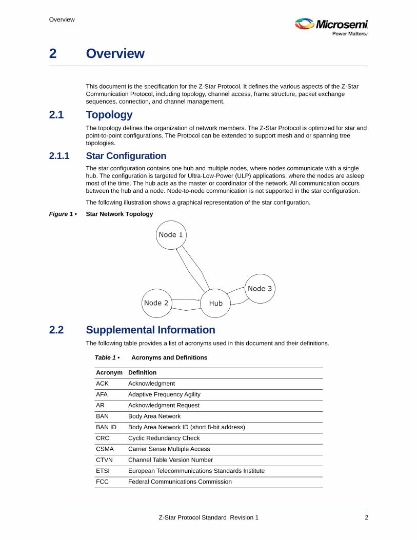
2.1.1 Star ConfigurationThe star configuration contains one hub and multiple nodes, where nodes communicate with a single hub. The configuration is targeted for Ultra-Low-Power (ULP) applications, where the nodes are asleep most of the time. The hub acts as the master or coordinator of the network. All communication occurs between the hub and a node. Node-to-node communication is not supported in the star configuration.
The following illustration shows a graphical representation of the star configuration.
Figure 1 • Star Network Topology
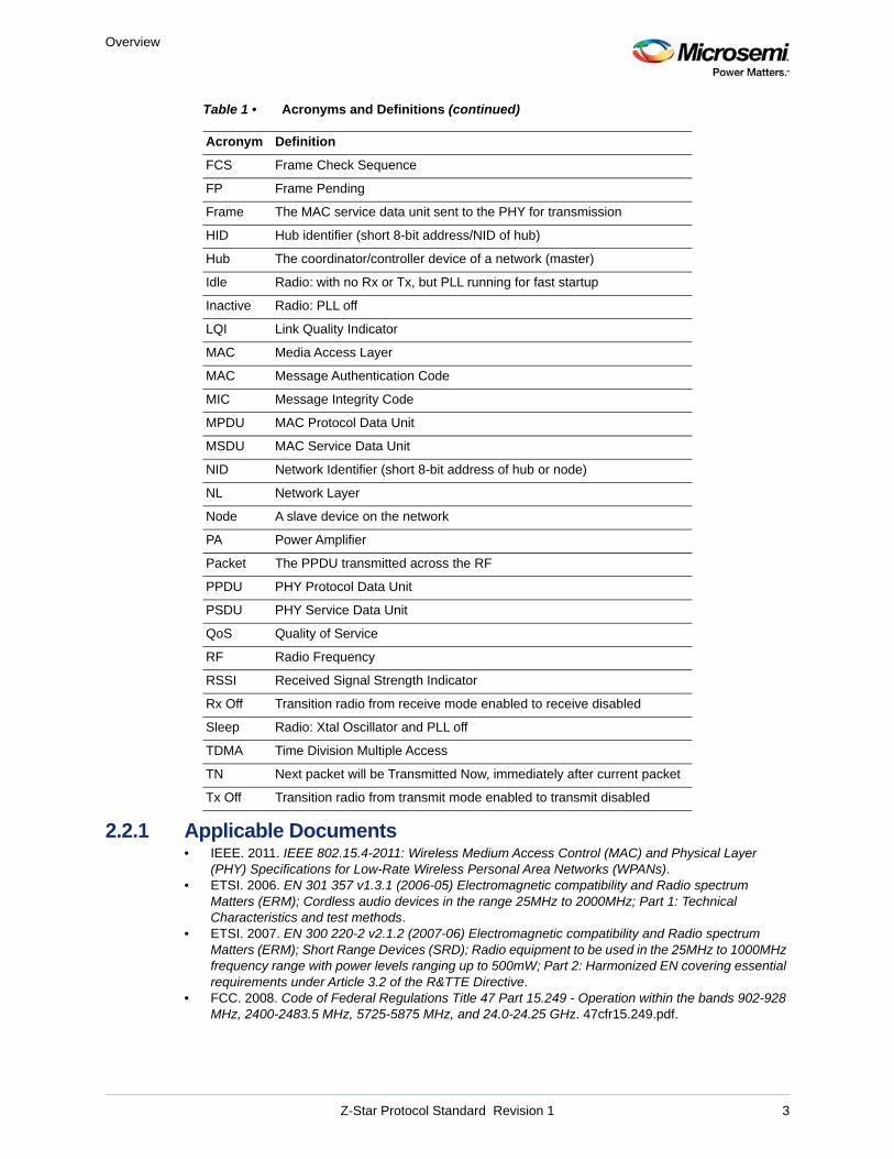
2.2 Supplemental InformationThe following table provides a list of acronyms used in this document and their definitions.
Table 1 • Acronyms and Definitions
Acronym Definition
ACK Acknowledgment
AFA Adaptive Frequency Agility
AR Acknowledgment Request
BAN Body Area Network
BAN ID Body Area Network ID (short 8-bit address)
CRC Cyclic Redundancy Check
CSMA Carrier Sense Multiple Access
CTVN Channel Table Version Number
ETSI European Telecommunications Standards Institute
FCC Federal Communications Commission
Node 1
Node 2
Node 3
Hub
Z-Star Protocol Standard Revision 1 2
Overview
2.2.1 Applicable Documents• IEEE. 2011. IEEE 802.15.4-2011: Wireless Medium Access Control (MAC) and Physical Layer
(PHY) Specifications for Low-Rate Wireless Personal Area Networks (WPANs).• ETSI. 2006. EN 301 357 v1.3.1 (2006-05) Electromagnetic compatibility and Radio spectrum
Matters (ERM); Cordless audio devices in the range 25MHz to 2000MHz; Part 1: Technical Characteristics and test methods.
• ETSI. 2007. EN 300 220-2 v2.1.2 (2007-06) Electromagnetic compatibility and Radio spectrum Matters (ERM); Short Range Devices (SRD); Radio equipment to be used in the 25MHz to 1000MHz frequency range with power levels ranging up to 500mW; Part 2: Harmonized EN covering essential requirements under Article 3.2 of the R&TTE Directive.
• FCC. 2008. Code of Federal Regulations Title 47 Part 15.249 - Operation within the bands 902-928 MHz, 2400-2483.5 MHz, 5725-5875 MHz, and 24.0-24.25 GHz. 47cfr15.249.pdf.
FCS Frame Check Sequence
FP Frame Pending
Frame The MAC service data unit sent to the PHY for transmission
HID Hub identifier (short 8-bit address/NID of hub)
Hub The coordinator/controller device of a network (master)
Idle Radio: with no Rx or Tx, but PLL running for fast startup
Inactive Radio: PLL off
LQI Link Quality Indicator
MAC Media Access Layer
MAC Message Authentication Code
MIC Message Integrity Code
MPDU MAC Protocol Data Unit
MSDU MAC Service Data Unit
NID Network Identifier (short 8-bit address of hub or node)
NL Network Layer
Node A slave device on the network
PA Power Amplifier
Packet The PPDU transmitted across the RF
PPDU PHY Protocol Data Unit
PSDU PHY Service Data Unit
QoS Quality of Service
RF Radio Frequency
RSSI Received Signal Strength Indicator
Rx Off Transition radio from receive mode enabled to receive disabled
Sleep Radio: Xtal Oscillator and PLL off
TDMA Time Division Multiple Access
TN Next packet will be Transmitted Now, immediately after current packet
Tx Off Transition radio from transmit mode enabled to transmit disabled
Table 1 • Acronyms and Definitions (continued)
Acronym Definition
Z-Star Protocol Standard Revision 1 3

Overview
• Microsemi Corporation. 2016. ZL70550 Programmer User's Guide for ZL70550 Ultra-Low-Power Sub-GHz RF Transceiver.
• Microsemi Corporation. 2016. ZL70550 Datasheet- Ultra-Low-Power Sub-GHz RF Transceiver.
Z-Star Protocol Standard Revision 1 4
Frame Format
3 Frame Format
Communication consists of a sequence of frame transactions between the hub and a node. Each frame type has a specific frame format, but in general, has similar headers and frame structures.
3.1 General Frame FormatThe Z-Star packet is used to transmit frames across the RF medium. Z-Star frames are contained within the Z-Star packet. The packet is the Z-Star frame, prepended with a preamble and frame sync pattern. The frame is used to transport information between the hub and node devices.
There are three types of frame format defined: short, normal, and long. The normal and long formats are identical except for the PHY header and the maximum frame length. The short frame format has a different MAC frame structure, as shown in Figure 7, page 18 and defined in Short Frame Format, page 17.
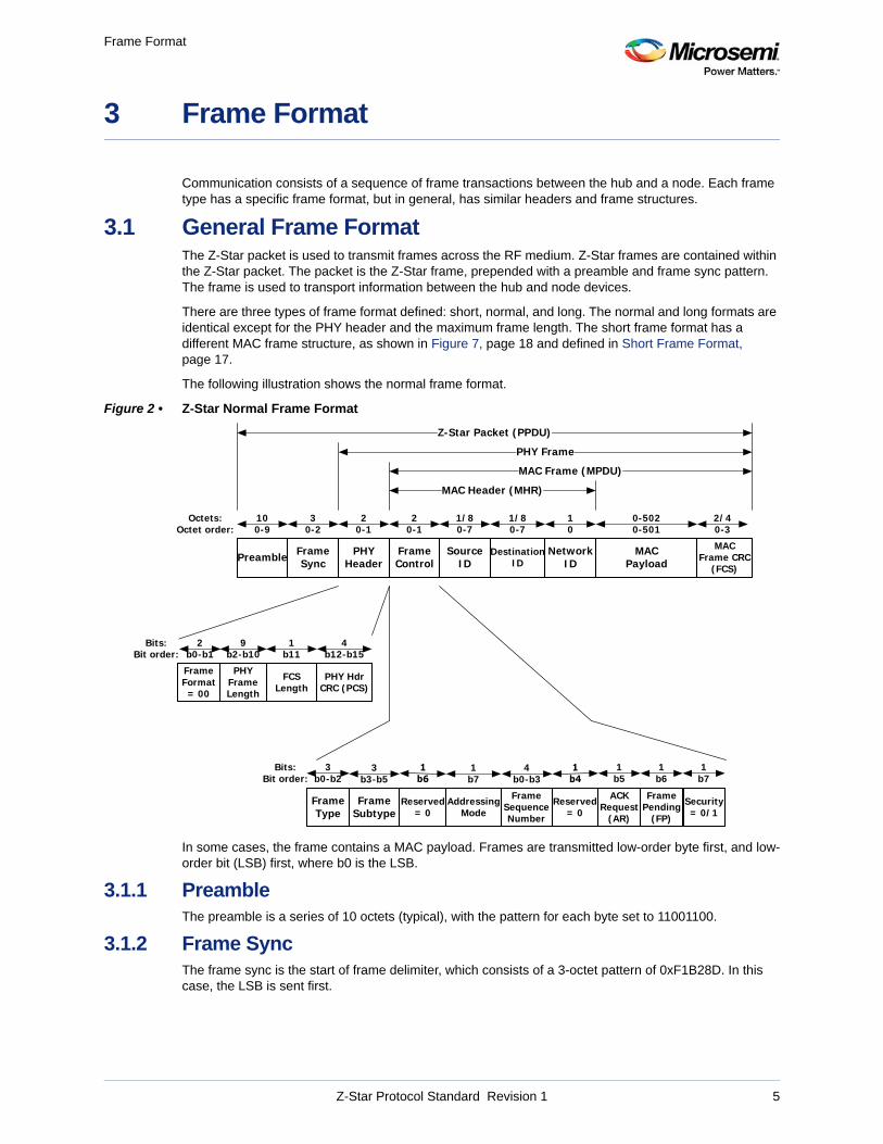
The following illustration shows the normal frame format.
Figure 2 • Z-Star Normal Frame Format
In some cases, the frame contains a MAC payload. Frames are transmitted low-order byte first, and low-order bit (LSB) first, where b0 is the LSB.
3.1.1 PreambleThe preamble is a series of 10 octets (typical), with the pattern for each byte set to 11001100.
3.1.2 Frame SyncThe frame sync is the start of frame delimiter, which consists of a 3-octet pattern of 0xF1B28D. In this case, the LSB is sent first.
FrameControl
NetworkID
SourceID
1/80-7
10
Octets:Octet order:
20-1
DestinationID
1/80-7
MAC Payload
0-5020-501
MAC Frame CRC
(FCS)
2/40-3
FramePending
(FP)
Reserved= 0
FrameType
1b5
ACKRequest
(AR)
1b6
AddressingMode
1b7
PHYHeader
20-1
Bits:Bit order:
3b0-b2
FrameSequenceNumber
4b0-b3
Security= 0/1
FrameSubtype
3b3-b5
Reserved= 0
1b7
MAC Header (MHR)
FrameSync
30-2
Preamble
100-9
Z-Star Packet (PPDU)
PHY Frame
MAC Frame (MPDU)
4b12-b15
PHYFrameLength
9b2-b10
PHY Hdr CRC (PCS)
Bits:Bit order:
FCSLength
1b11
FrameFormat= 00
2b0-b1
Z-Star Protocol Standard Revision 1 5
Frame Format
3.1.3 PHY HeaderThe PHY header consists of the length of the MAC frame (MPDU), the FCS length, and the PHY header CRC (PCS). The PHY header for normal frames in shown in Figure 2, page 5.
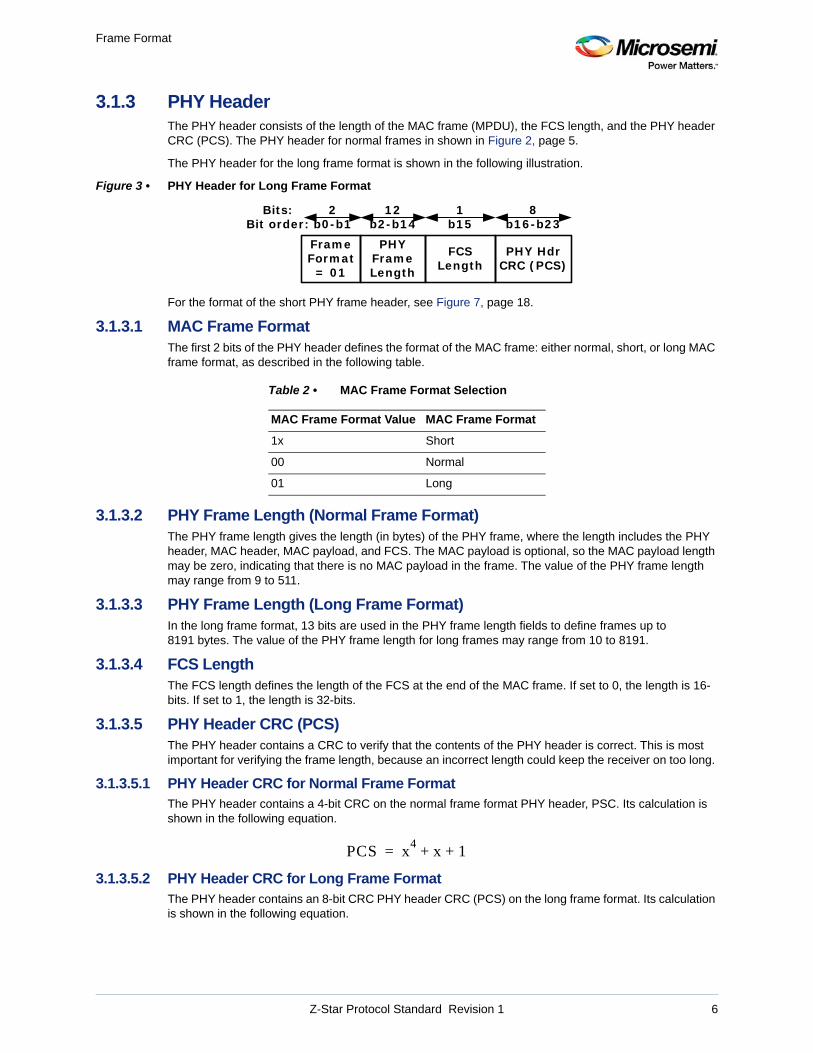
The PHY header for the long frame format is shown in the following illustration.
Figure 3 • PHY Header for Long Frame Format
For the format of the short PHY frame header, see Figure 7, page 18.
3.1.3.1 MAC Frame FormatThe first 2 bits of the PHY header defines the format of the MAC frame: either normal, short, or long MAC frame format, as described in the following table.
3.1.3.2 PHY Frame Length (Normal Frame Format)The PHY frame length gives the length (in bytes) of the PHY frame, where the length includes the PHY header, MAC header, MAC payload, and FCS. The MAC payload is optional, so the MAC payload length may be zero, indicating that there is no MAC payload in the frame. The value of the PHY frame length may range from 9 to 511.
3.1.3.3 PHY Frame Length (Long Frame Format)In the long frame format, 13 bits are used in the PHY frame length fields to define frames up to 8191 bytes. The value of the PHY frame length for long frames may range from 10 to 8191.
3.1.3.4 FCS LengthThe FCS length defines the length of the FCS at the end of the MAC frame. If set to 0, the length is 16-bits. If set to 1, the length is 32-bits.
3.1.3.5 PHY Header CRC (PCS)The PHY header contains a CRC to verify that the contents of the PHY header is correct. This is most important for verifying the frame length, because an incorrect length could keep the receiver on too long.
3.1.3.5.1 PHY Header CRC for Normal Frame FormatThe PHY header contains a 4-bit CRC on the normal frame format PHY header, PSC. Its calculation is shown in the following equation.
3.1.3.5.2 PHY Header CRC for Long Frame FormatThe PHY header contains an 8-bit CRC PHY header CRC (PCS) on the long frame format. Its calculation is shown in the following equation.
Table 2 • MAC Frame Format Selection
MAC Frame Format Value MAC Frame Format
1x Short
00 Normal
01 Long
8b16-b23
PHYFrameLength
12b2-b14
PHY Hdr CRC (PCS)
Bits:Bit order:
FCSLength
1b15
FrameFormat
= 01
2b0-b1
PCS x4
x 1+ +=
Z-Star Protocol Standard Revision 1 6
Frame Format
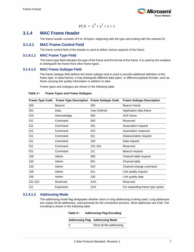
3.1.4 MAC Frame HeaderThe frame header consists of 5 to 19 bytes, beginning with the type and ending with the network ID.
3.1.4.1 MAC Frame Control FieldThe frame control field of the header is used to define various aspects of the frame.
3.1.4.1.1 MAC Frame Type FieldThe frame type field indicates the type of the frame and the format of the frame. It is used by the recipient to distinguish the frame from other frame types.
3.1.4.1.2 MAC Frame Subtype FieldThe frame subtype field defines the frame subtype and is used to provide additional definition of the frame type. In data frames, it may distinguish different data types, or different payload formats, such as those carrying link quality information in addition to data.
Frame types and subtypes are shown in the following table.
3.1.4.1.3 Addressing ModeThe addressing mode flag designates whether short or long addressing is being used. Long addresses are unique 64-bit addresses, used primarily for the connection process. Short addresses are 8-bit. The encoding is shown in the following table.
Table 3 • Frame Types and Frame Subtypes
Frame Type Code Frame Type Description Frame Subtype Code Frame Subtype Description
000 Beacon 000 Beacon frame
001 Data User Defined Application data frame
010 Acknowledge 000 ACK frame
011 Command 000 Reserved
011 Command 001 Association request
011 Command 010 Association response
011 Command 011 Disassociation request
011 Command 100 Data request
011 Command 101–011 Reserved
011 Command 111 Beacon request
100 Admin 000 Channel table request
100 Admin 001 Channel table
100 Admin 010 Channel change command
100 Admin 011 Link quality request
100 Admin 100 Link quality data
101-110 Reserved XXX Reserved
111 Expansion XXX For expanding frame type space
Table 4 • Addressing Flag Encoding
Addressing Flag Addressing Mode
0 Short (8-bit) addressing
PCS x8
x2
x 1+ + +=
Z-Star Protocol Standard Revision 1 7
Frame Format
The short and long addresses apply to the source and destination addresses in the MAC header.
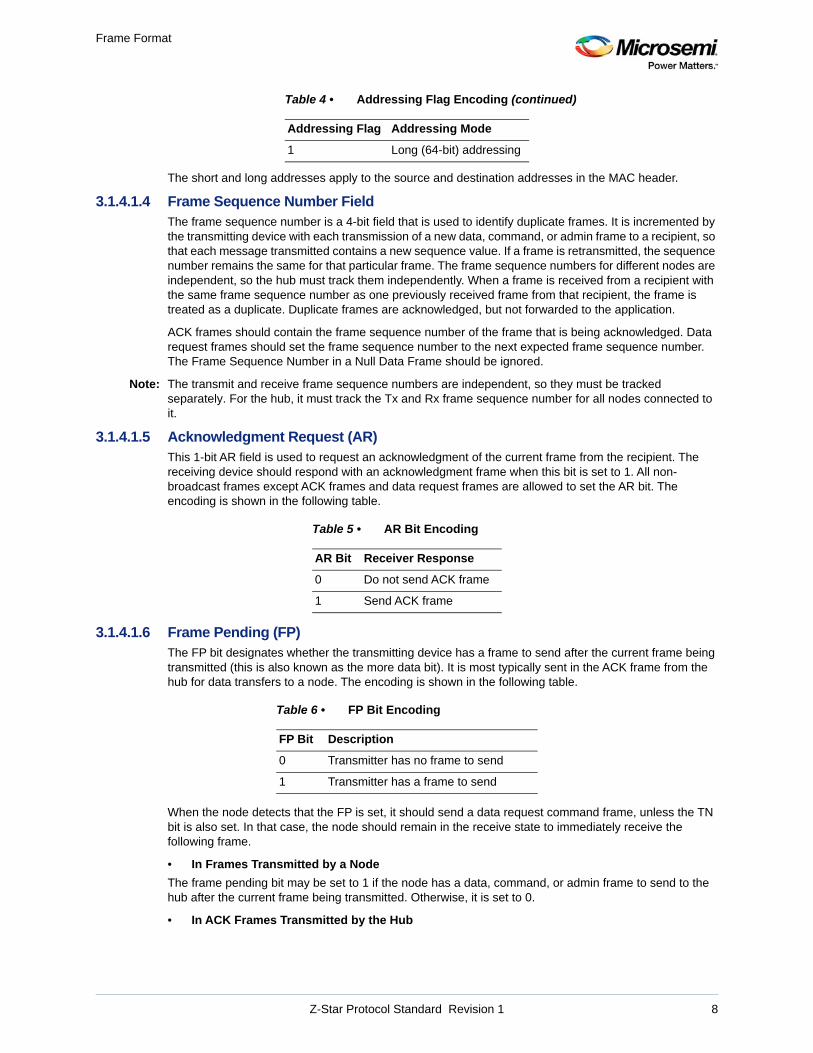
3.1.4.1.4 Frame Sequence Number FieldThe frame sequence number is a 4-bit field that is used to identify duplicate frames. It is incremented by the transmitting device with each transmission of a new data, command, or admin frame to a recipient, so that each message transmitted contains a new sequence value. If a frame is retransmitted, the sequence number remains the same for that particular frame. The frame sequence numbers for different nodes are independent, so the hub must track them independently. When a frame is received from a recipient with the same frame sequence number as one previously received frame from that recipient, the frame is treated as a duplicate. Duplicate frames are acknowledged, but not forwarded to the application.
ACK frames should contain the frame sequence number of the frame that is being acknowledged. Data request frames should set the frame sequence number to the next expected frame sequence number. The Frame Sequence Number in a Null Data Frame should be ignored.
Note: The transmit and receive frame sequence numbers are independent, so they must be tracked separately. For the hub, it must track the Tx and Rx frame sequence number for all nodes connected to it.
3.1.4.1.5 Acknowledgment Request (AR)This 1-bit AR field is used to request an acknowledgment of the current frame from the recipient. The receiving device should respond with an acknowledgment frame when this bit is set to 1. All non-broadcast frames except ACK frames and data request frames are allowed to set the AR bit. The encoding is shown in the following table.
3.1.4.1.6 Frame Pending (FP)The FP bit designates whether the transmitting device has a frame to send after the current frame being transmitted (this is also known as the more data bit). It is most typically sent in the ACK frame from the hub for data transfers to a node. The encoding is shown in the following table.
When the node detects that the FP is set, it should send a data request command frame, unless the TN bit is also set. In that case, the node should remain in the receive state to immediately receive the following frame.
• In Frames Transmitted by a Node
The frame pending bit may be set to 1 if the node has a data, command, or admin frame to send to the hub after the current frame being transmitted. Otherwise, it is set to 0.
• In ACK Frames Transmitted by the Hub
1 Long (64-bit) addressing
Table 5 • AR Bit Encoding
AR Bit Receiver Response
0 Do not send ACK frame
1 Send ACK frame
Table 6 • FP Bit Encoding
FP Bit Description
0 Transmitter has no frame to send
1 Transmitter has a frame to send
Table 4 • Addressing Flag Encoding (continued)
Addressing Flag Addressing Mode
Z-Star Protocol Standard Revision 1 8
Frame Format
The frame pending bit is set to 1 if the hub has a data, command, or admin frame to send to the node after the current frame. Otherwise, it is set to 0. When set to 1 with TN = 0, the node should send a data request command frame to the hub. It should then switch to receive mode, so that the node can receive the next frame from the hub.
If both the FP and TN bits are set to 1 in the ACK frame from the hub, then the hub will immediately send the data, command, or admin frame to the node. In this case, the node shall stay in receive mode to receive the frame.
If the FP bit is set to 0 in a received ACK frame, the node may enter the sleep state after receiving the ACK frame.
• In Other Frames Transmitted by the Hub
If the frame pending bit is set to 1 in a data, command, or admin frame sent to the node, then the node should send another data request frame to the hub after sending the ACK frame. If the FP bit is set to 0 in a data, command, or admin frame sent to the node, the node may enter the sleep state after sending the ACK frame.
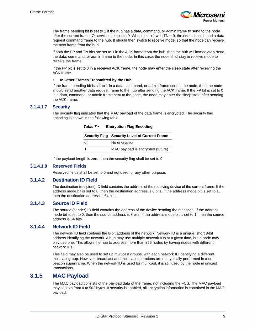
3.1.4.1.7 SecurityThe security flag indicates that the MAC payload of the data frame is encrypted. The security flag encoding is shown in the following table.
If the payload length is zero, then the security flag shall be set to 0.
3.1.4.1.8 Reserved FieldsReserved fields shall be set to 0 and not used for any other purpose.
3.1.4.2 Destination ID FieldThe destination (recipient) ID field contains the address of the receiving device of the current frame. If the address mode bit is set to 0, then the destination address is 8 bits. If the address mode bit is set to 1, then the destination address is 64 bits.
3.1.4.3 Source ID FieldThe source (sender) ID field contains the address of the device sending the message. If the address mode bit is set to 0, then the source address is 8 bits. If the address mode bit is set to 1, then the source address is 64 bits.
3.1.4.4 Network ID FieldThe network ID field contains the 8-bit address of the network. Network ID is a unique, short 8-bit address identifying the network. A hub may use multiple network IDs at a given time, but a node may only use one. This allows the hub to address more than 255 nodes by having nodes with different network IDs.
This field may also be used to set up multicast groups, with each network ID identifying a different multicast group. However, broadcast and multicast operations are not typically performed in a non-beacon superframe. When the network ID is used for multicast, it is still used by the node in unicast transactions.
3.1.5 MAC PayloadThe MAC payload consists of the payload data of the frame, not including the FCS. The MAC payload may contain from 0 to 502 bytes. If security is enabled, all encryption information is contained in the MAC payload.
Table 7 • Encryption Flag Encoding
Security Flag Security Level of Current Frame
0 No encryption
1 MAC payload is encrypted (future)
Z-Star Protocol Standard Revision 1 9
Frame Format
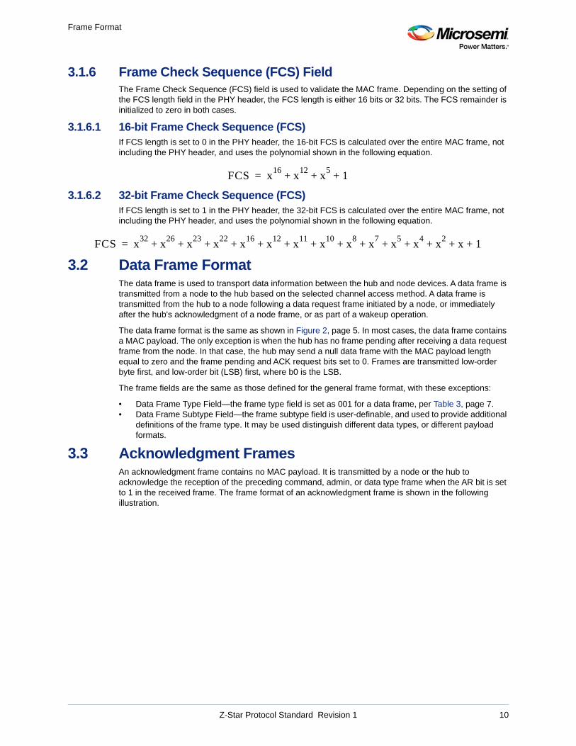
3.1.6 Frame Check Sequence (FCS) FieldThe Frame Check Sequence (FCS) field is used to validate the MAC frame. Depending on the setting of the FCS length field in the PHY header, the FCS length is either 16 bits or 32 bits. The FCS remainder is initialized to zero in both cases.
3.1.6.1 16-bit Frame Check Sequence (FCS)If FCS length is set to 0 in the PHY header, the 16-bit FCS is calculated over the entire MAC frame, not including the PHY header, and uses the polynomial shown in the following equation.
3.1.6.2 32-bit Frame Check Sequence (FCS)If FCS length is set to 1 in the PHY header, the 32-bit FCS is calculated over the entire MAC frame, not including the PHY header, and uses the polynomial shown in the following equation.
3.2 Data Frame FormatThe data frame is used to transport data information between the hub and node devices. A data frame is transmitted from a node to the hub based on the selected channel access method. A data frame is transmitted from the hub to a node following a data request frame initiated by a node, or immediately after the hub's acknowledgment of a node frame, or as part of a wakeup operation.
The data frame format is the same as shown in Figure 2, page 5. In most cases, the data frame contains a MAC payload. The only exception is when the hub has no frame pending after receiving a data request frame from the node. In that case, the hub may send a null data frame with the MAC payload length equal to zero and the frame pending and ACK request bits set to 0. Frames are transmitted low-order byte first, and low-order bit (LSB) first, where b0 is the LSB.
The frame fields are the same as those defined for the general frame format, with these exceptions:
• Data Frame Type Field—the frame type field is set as 001 for a data frame, per Table 3, page 7.• Data Frame Subtype Field—the frame subtype field is user-definable, and used to provide additional
definitions of the frame type. It may be used distinguish different data types, or different payload formats.
3.3 Acknowledgment FramesAn acknowledgment frame contains no MAC payload. It is transmitted by a node or the hub to acknowledge the reception of the preceding command, admin, or data type frame when the AR bit is set to 1 in the received frame. The frame format of an acknowledgment frame is shown in the following illustration.
FCS x16
x12
x5
1+ + +=
FCS x32
x26
x23
x22
x16
x12
x11
x10
x8
x7
x5
x4
x2
x 1+ + + + + + + + + + + + + +=
Z-Star Protocol Standard Revision 1 10
Frame Format
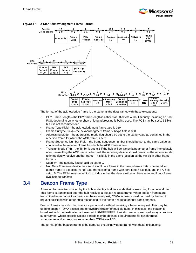
Figure 4 • Z-Star Acknowledgment Frame Format
The format of the acknowledge frame is the same as the data frame, with these exceptions:
• PHY Frame Length—the PHY frame length is either 9 or 23 octets without security, including a 16-bit FCS, depending on whether short or long addressing is being used. The FCS may be set to 32-bits, but it is not recommended.
• Frame Type Field—the acknowledgment frame type is 010. • Frame Subtype Field—the acknowledgment frame subtype field is 000.• Addressing Mode—the addressing mode flag should be set to the same value as contained in the
received frame for which the ACK frame is sent.• Frame Sequence Number Field—the frame sequence number should be set to the same value as
contained in the received frame for which the ACK frame is sent.• Transmit Mode (TN)—the TN bit is set to 1 if the hub will be transmitting another frame immediately
after transmitting the ACK frame. When set, the receiving device should remain in the receive mode to immediately receive another frame. This bit is in the same location as the AR bit in other frame formats.
• Security—the security flag should be set to 0.• Null Data Frame—a device may send a null data frame in the case where a data, command, or
admin frame is expected. A null data frame is data frame with zero length payload, and the AR bit set to 0. The FP bit may be set to 1 to indicate that the device will soon have a non-null data frame available to transmit.
3.4 Beacon Frame TypeA beacon frame is transmitted by the hub to identify itself to a node that is searching for a network hub. This frame is transmitted after the hub receives a beacon request frame. When beacon frames are transmitted in response to a broadcast beacon request, CSMA access should be used by the hub to prevent collisions with other hubs responding to the beacon request on that same channel.
Beacon frames may also be broadcast periodically without receiving a beacon request. This may be used to support TDMA access and for synchronization of multiple hubs. In this case, the beacon is broadcast with the destination address set to 0xFFFFFFFF. Periodic beacons are used for synchronous superframes, where specific access periods may be defines. Requirements for synchronous superframes and access modes other than CSMA are TBD.
The format of the beacon frame is the same as the acknowledge frame, with these exceptions:
FrameControl
NetworkID
SourceID
1/80-7
10
Octets:Octet order:
20-1
DestinationID
1/80-7
Frame CRC
(FCS)
20-1
PHYHeader
20-1
FrameSync
30-2
Preamble
100-9
FramePending= 1/0 (FP)
Reserved= 0
FrameType= 010
1b6
1b6
AddressingMode= 1/0
1b7
Bits:Bit order:
3b0-b2
1b4
FrameSequenceNumber
4b0-b3
FrameSubtype= 000
3b3-b5
Reserved= 0
1b7
1b5
Tx Now(TN)
Security= 0/1
4b12-b15
PHYFrameLength
9b2-b10
PHY Hdr CRC (PCS)
Bits:Bit order:
FCSLength
= 0
1b11
FrameFormat= 00
2b0-b1
Z-Star Protocol Standard Revision 1 11
Frame Format
• MAC Frame Length—the MAC frame length is 19 octets, because only long addressing is being used. There is never a MAC payload in a beacon frame of subtype 000.
• Frame Type Field—the beacon frame type is 000.• Frame Subtype Field—the beacon frame subtype is 000. There may be other subtypes in the future.• Addressing Mode—the addressing mode flag should be set to 1 for long addressing.• Sequence Number Field—the sequence number should be set to the same value as contained in
the received beacon request frame for which the beacon frame is sent.• Acknowledgment Request (AR)—AR is set to 0 in a beacon frame if the destination address is a
broadcast address. Otherwise, it is typically set to 1.• Frame Pending (FP)—FP is always set to 0 in a beacon frame of subtype 000. This may not be true
for other future subtypes.• Security—the security flag is always set to 0 in beacon frames of subtype 000.
• Destination ID Field—the destination (recipient) ID field contains the 64-bit long address of the requesting node. If the beacon frame is sent as a broadcast frame, then the destination (recipient) ID field contains 0xFFFFFFFF.
• Source ID Field—the source (sender) ID field contains the 64-bit long address of the device sending the beacon.
• Network ID Field—the network ID field contains 0x00. This field should be ignored by the receiving device when the addressing mode bit is set to long addressing.
3.5 Command Type FramesThe command type frames are shown in Table 3, page 7. Command frames all have a frame type of 011.
3.5.1 Association Request Frame TimeAn association request frame is used by a node to request connection to the hub. Long addressing is always used, and the AR bit should be set to 1. There may be additional information in the MAC payload to identify the node. This information could include such information as serial number, measurement type, measurement rate, and so on. This MAC payload is application specific, and not defined by the Z-Star Protocol.
After sending the association request frame and receiving the associated ACK frame, the node should wait for an aTimeAssocReq time interval, and then send a data request command to the hub.
If the node receives a null data frame with a MAC payload length of zero, then it should wait for another aTimeAssocReq time interval and then send another data request frame.
The format of the association request frame is the same as the data frame with these exceptions:
• Frame Type Field—the association request frame type is 011.• Frame Subtype Field—the association request frame subtype is 001. • Addressing Mode—the addressing mode flag should be set to 1 for long addressing.• Frame Sequence Number Field—the frame sequence number should be set to 0.• Acknowledgment Request (AR)—AR is always set to 1 in an association request frame.• Frame Pending (FP)—FP is always set to 0 in an association request frame.• Security—the security flag is always set to 0 in an association request frame.• Source ID Field—the source (sending) ID field contains the long 64-bit address of the node.• Destination ID Field—the destination (recipient) ID field contains the long 64-bit address of the hub
that was received in the beacon frame for the hub to which the node chooses to connect.• Network ID Field—the network ID field contains the 0x00. This field should be ignored by the
receiving device when the addressing mode bit is set to long addressing.
3.5.2 Association Response Frame TypeAn association response frame is sent by a hub in response to a data request frame after previously receiving an association request frame from the node. Long addressing is always used, and the AR bit should be set to 1. There is additional information in the MAC payload to identify the short addresses and the association status. The format is shown in the following illustration.
Z-Star Protocol Standard Revision 1 12
Frame Format
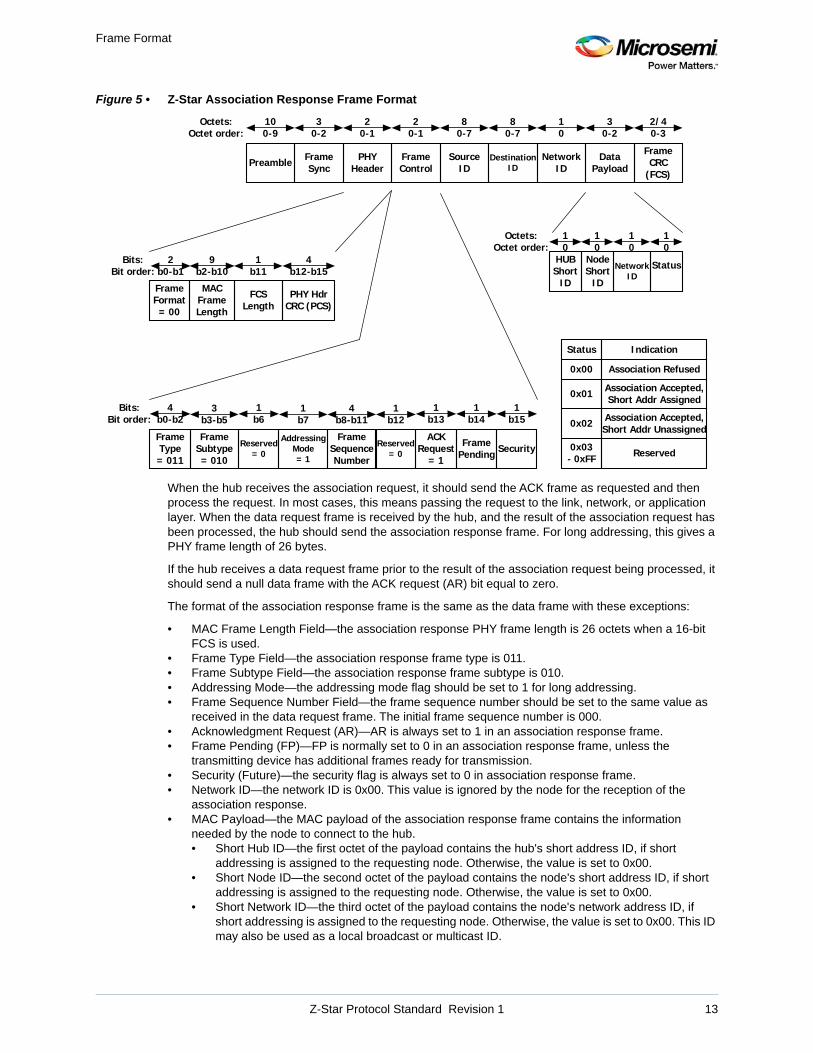
Figure 5 • Z-Star Association Response Frame Format
When the hub receives the association request, it should send the ACK frame as requested and then process the request. In most cases, this means passing the request to the link, network, or application layer. When the data request frame is received by the hub, and the result of the association request has been processed, the hub should send the association response frame. For long addressing, this gives a PHY frame length of 26 bytes.
If the hub receives a data request frame prior to the result of the association request being processed, it should send a null data frame with the ACK request (AR) bit equal to zero.
The format of the association response frame is the same as the data frame with these exceptions:
• MAC Frame Length Field—the association response PHY frame length is 26 octets when a 16-bit FCS is used.
• Frame Type Field—the association response frame type is 011.• Frame Subtype Field—the association response frame subtype is 010.• Addressing Mode—the addressing mode flag should be set to 1 for long addressing.• Frame Sequence Number Field—the frame sequence number should be set to the same value as
received in the data request frame. The initial frame sequence number is 000.• Acknowledgment Request (AR)—AR is always set to 1 in an association response frame.• Frame Pending (FP)—FP is normally set to 0 in an association response frame, unless the
transmitting device has additional frames ready for transmission.• Security (Future)—the security flag is always set to 0 in association response frame.• Network ID—the network ID is 0x00. This value is ignored by the node for the reception of the
association response.• MAC Payload—the MAC payload of the association response frame contains the information
needed by the node to connect to the hub.• Short Hub ID—the first octet of the payload contains the hub's short address ID, if short
addressing is assigned to the requesting node. Otherwise, the value is set to 0x00.• Short Node ID—the second octet of the payload contains the node's short address ID, if short
addressing is assigned to the requesting node. Otherwise, the value is set to 0x00.• Short Network ID—the third octet of the payload contains the node's network address ID, if
short addressing is assigned to the requesting node. Otherwise, the value is set to 0x00. This ID may also be used as a local broadcast or multicast ID.
NetworkID
SourceID
80-7
10
Octets:Octet order:
FrameControl
20-1
DestinationID
80-7
DataPayload
30-2
Frame CRC
(FCS)
2/40-3
FramePending
Reserved= 0
FrameType= 011
1b6
1b13
ACKRequest
= 1
1b14
AddressingMode= 1
1b7
PHYHeader
20-1
Bits:Bit order:
4b0-b2
1b12
FrameSequenceNumber
4b8-b11
SecurityFrame
Subtype= 010
3b3-b5
Reserved= 0
1b15
StatusHUBShort
ID
10
Octets:Octet order:
10
NodeShort
ID
Status Indication
0x00 Association Refused
0x01 Association Accepted,Short Addr Assigned
0x02 Association Accepted,Short Addr Unassigned
0x03- 0xFF Reserved
FrameSync
30-2
Preamble
100-9
4b12-b15
MACFrameLength
9b2-b10
PHY Hdr CRC (PCS)
Bits:Bit order:
FCSLength
1b11
FrameFormat= 00
2b0-b1 Network
ID
10
10
Z-Star Protocol Standard Revision 1 13
Frame Format
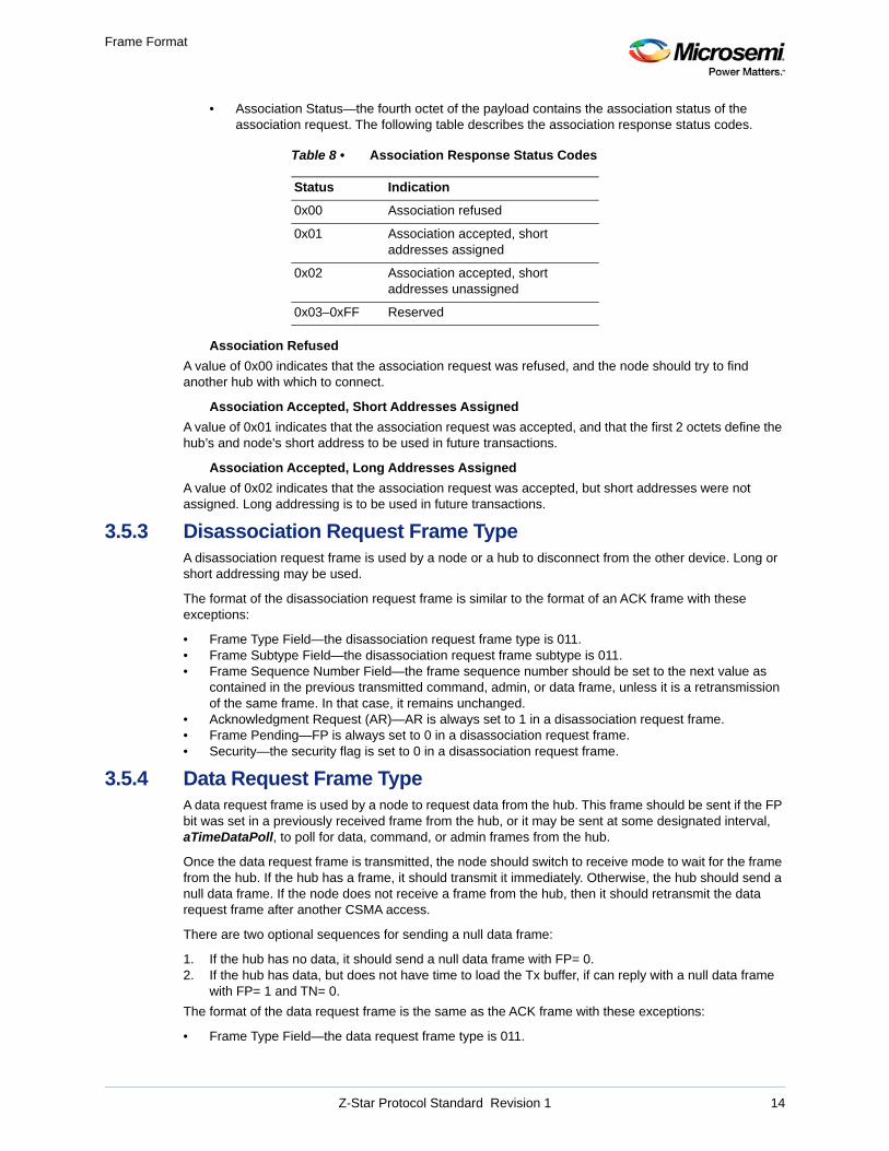
• Association Status—the fourth octet of the payload contains the association status of the association request. The following table describes the association response status codes.
Association Refused
A value of 0x00 indicates that the association request was refused, and the node should try to find another hub with which to connect.
Association Accepted, Short Addresses Assigned
A value of 0x01 indicates that the association request was accepted, and that the first 2 octets define the hub’s and node's short address to be used in future transactions.
Association Accepted, Long Addresses Assigned
A value of 0x02 indicates that the association request was accepted, but short addresses were not assigned. Long addressing is to be used in future transactions.
3.5.3 Disassociation Request Frame TypeA disassociation request frame is used by a node or a hub to disconnect from the other device. Long or short addressing may be used.
The format of the disassociation request frame is similar to the format of an ACK frame with these exceptions:
• Frame Type Field—the disassociation request frame type is 011.• Frame Subtype Field—the disassociation request frame subtype is 011.• Frame Sequence Number Field—the frame sequence number should be set to the next value as
contained in the previous transmitted command, admin, or data frame, unless it is a retransmission of the same frame. In that case, it remains unchanged.
• Acknowledgment Request (AR)—AR is always set to 1 in a disassociation request frame.• Frame Pending—FP is always set to 0 in a disassociation request frame.• Security—the security flag is set to 0 in a disassociation request frame.
3.5.4 Data Request Frame TypeA data request frame is used by a node to request data from the hub. This frame should be sent if the FP bit was set in a previously received frame from the hub, or it may be sent at some designated interval, aTimeDataPoll, to poll for data, command, or admin frames from the hub.
Once the data request frame is transmitted, the node should switch to receive mode to wait for the frame from the hub. If the hub has a frame, it should transmit it immediately. Otherwise, the hub should send a null data frame. If the node does not receive a frame from the hub, then it should retransmit the data request frame after another CSMA access.
There are two optional sequences for sending a null data frame:
1. If the hub has no data, it should send a null data frame with FP= 0.2. If the hub has data, but does not have time to load the Tx buffer, if can reply with a null data frame
with FP= 1 and TN= 0.
The format of the data request frame is the same as the ACK frame with these exceptions:
• Frame Type Field—the data request frame type is 011.
Table 8 • Association Response Status Codes
Status Indication
0x00 Association refused
0x01 Association accepted, short addresses assigned
0x02 Association accepted, short addresses unassigned
0x03–0xFF Reserved
Z-Star Protocol Standard Revision 1 14
Frame Format
• Frame Subtype Field—the data request frame subtype is 100.• Frame Sequence Number Field—the frame sequence number should be set to the next expected
frame sequence number. Note: The hub may use this number to transmit the next frame to the node.
• Acknowledgment Request (AR)—AR is always set to 0 in a data request frame.• Frame Pending—FP is normally set to 0 in a data request frame.• Security (Future)—the security flag is always set to a 0 in a data request frame.
3.5.5 Beacon Request Frame TypeA beacon request frame is used by a node to search for a hub/network after startup, after disassociating from another hub, or after receiving a denial for an association request. This frame is sent with the node's long address for the source ID and the long broadcast address, 0xFFFFFF, in the destination ID, and 0x00 in the network ID.
Beacon frames are typically sent unicast to the requesting node with the AR bit set. This means that the node shall acknowledge the beacon using long addressing.
The format of the beacon request frame is the same as the ACK frame with the following exceptions:
• Frame Type Field—the beacon request frame type is 011.• Frame Subtype Field—the beacon request frame subtype is 111.• Addressing Mode—the addressing mode flag should be set to 1 for long addressing.• Frame Sequence Number Field—the frame sequence number should be set to 0, and not
incremented between frames. • Frame Pending (FP)—FP is always set to 0 in a beacon request frame.• Security—the security flag is always set to 0 in a beacon request frame.• Destination ID Field—the destination (recipient) ID field contains the long 64-bit broadcast address,
0xFFFFFF.• Network ID Field—the network ID field contains 0x00.• Source ID Field—the source (sending) ID field contains the long 64-bit address of the node.
3.6 Administration Type Frames
3.6.1 Channel Table Request Frame TypeA channel table request frame is used by a node to request an updated channel table from the hub. This is normally done after association, or when the node decides that its channel table may be stale.
After sending the channel table request frame and receiving the associated ACK frame, the node should then send a data request frame after another CSMA to receive the channel table frame.
The format of the channel table request frame is the same as the ACK frame with these exceptions:
• Frame Type Field—the channel table request frame type is 100.• Frame Subtype Field—the channel table request frame subtype is 000.• Frame Sequence Number Field—the frame sequence number should be set to the next value as
contained in the previously transmitted command, admin, or data frame, unless it is a retransmission of the same frame. In that case, it remains unchanged.
• Acknowledgment Request (AR)—AR is always set to 1 in a channel table request frame.• Frame Pending (FP)—FP is normally set to 0 in a channel table request frame.• Security—the security flag may be set to 0 in a channel table request frame.
3.6.2 Channel Table Frame TypeA channel table frame is sent to a node from the hub to update the channel table. This can be done as the result of a channel table request frame, or when the hub updates the channel table. It is sent after a data request frame is received from the node. The channel table is contained in the MAC payload of the channel table frame.
The format of the channel table frame is the same as the data frame with these exceptions:
• Frame Type Field—the channel table frame type is 100.
Z-Star Protocol Standard Revision 1 15
Frame Format
• Frame Subtype Field—the channel table frame subtype is 001.• Frame Sequence Number Field—the frame sequence number should be set to the value contained
in the data request frame that follows the channel table request frame.• Acknowledgment Request (AR)—AR is always set to 1 in a channel table frame.• Frame Pending (FP)—FP is normally set to 0 in a channel table frame.• Security—the security flag may be set to either a 0 or 1 in a channel table frame.• MAC Payload—the MAC payload of the channel table frame contains the Channel Table Revision
(CTVN) followed by the ordered list of channels to which a node will scan in the event that the node loses communication with the hub.• Channel Table Revision (CTVN)—the first octet of the payload contains the channel table
revision, switching increments sequentially starting a 0x01 for each version of the channel table. If 0xFF is reached, then the numbering wraps back to 0x01. 0x00 is reserved to indicate no channel table revision is being used.
• Channels—the remaining octets of the payload comprise an ordered list of channel numbers, in the range of 0x01 to 0xFF. The number of channels contained in the table is determined by the MAC frame length and the addressing mode.
Note: The mapping of the channel numbers to channel frequencies is dependent of the RF band being used. The device firmware should have a mapping of the channel numbers to frequency setup values for the device.
3.6.3 Channel Change Command Frame TypeA channel change command frame is sent to a node from the hub, to command the node to change channels. The command may be either an immediate command or a scheduled channel change that will take place at a specified time in the future. The channel change information is contained in the MAC payload of the channel change command frame.
The format of the channel change command frame is the same as the data frame with these exceptions:
• Frame Type Field—the channel change frame type is 100.• Frame Subtype Field—the acknowledgment frame subtype is 010.• Frame Sequence Number Field—the frame sequence number should be set to the next value as
contained in the previous transmitted command, admin, or data frame, unless it is a retransmission of the same frame. In that case, it remains unchanged.
• Acknowledgment Request (AR)—AR is always set to 1 in a channel change command frame.• Frame Pending (FP)—FP is normally set to 0 in a channel change command frame.• Security (Future)—the security flag is set to either 1 or 0 in a channel change command frame.• MAC Payload—the MAC payload of the channel change command frame contains the channel
number to which a node will change, and the time of effectiveness.• Channel Number—the first octet of the MAC payload contains the channel number to which the
node should change.• Effective Time of Channel Change—the remaining 2 octets of the payload are comprised of the
time at which the channel time is effective. A 0x0000 indicates that the channel change is effective immediately. All other values indicate the number of 10 msec intervals to which the channel change is to become effective.
Note: This is not a broadcast command; the nodes will be receiving this command at different times. Therefore, the channel change time must be updated for every channel change command sent. It may not be practical to simply place the command frame in the transmit buffers for a node, waiting for a packet from the node to initiate the transmission of the change channel command.
3.6.4 Link Quality Request Frame TypeA link quality request frame is used by the hub to request a link quality frame from a node.
The format of the link quality request frame is the same as the ACK frame with these exceptions:
• Frame Type Field—the link quality request frame type is 100.• Frame Subtype Field—the link quality frame subtype is 011.• Frame Sequence Number Field—the frame sequence number should be set to the next value as
contained in the previous transmitted command, admin, or data frame, unless it is a retransmission of the same frame. In that case, it remains unchanged.
• Acknowledgment Request (AR)—AR is always set to 1 in a link quality request frame.
Z-Star Protocol Standard Revision 1 16
Frame Format
• Frame Pending (FP)—FP is normally set to 0 in a link quality request frame.• Security (Future)—the security flag is set to 0 in a link quality request frame.
3.6.5 Link Quality Data Frame TypeA link qualify data frame is sent from a node to the hub in response to a link qualify request frame from the hub. The link quality data is contained in the MAC payload of the link qualify data frame.
The format of the link qualify data frame is the same as the data frame with these exceptions:
• Frame Type Field—the link qualify data frame type is 100.• Frame Subtype Field—the link qualify data frame subtype is 100.• Frame Sequence Number Field—the frame sequence number should be set to the next value as
contained in the previous transmitted data frame, unless it is a retransmission of the same frame. In that case, it remains unchanged.
• Acknowledgment Request (AR)—AR is always set to 1 in a link qualify data frame.• Frame Pending (FP)—FP is normally set to 0 in a link qualify data frame.• Security (Future)—the security flag may be set to either 0 or 1 in a link qualify data frame.• MAC Payload—the MAC payload of the link qualify data frame contains the link quality data. The
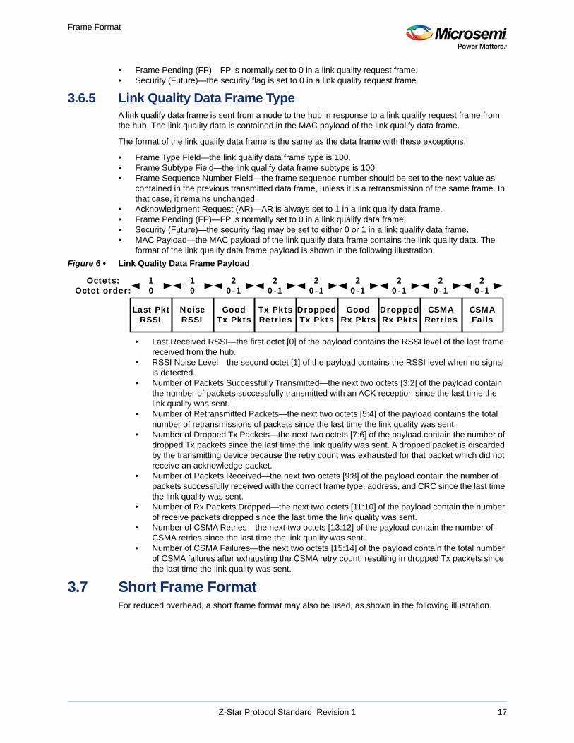
format of the link qualify data frame payload is shown in the following illustration.
Figure 6 • Link Quality Data Frame Payload
• Last Received RSSI—the first octet [0] of the payload contains the RSSI level of the last frame received from the hub.
• RSSI Noise Level—the second octet [1] of the payload contains the RSSI level when no signal is detected.
• Number of Packets Successfully Transmitted—the next two octets [3:2] of the payload contain the number of packets successfully transmitted with an ACK reception since the last time the link quality was sent.
• Number of Retransmitted Packets—the next two octets [5:4] of the payload contains the total number of retransmissions of packets since the last time the link quality was sent.
• Number of Dropped Tx Packets—the next two octets [7:6] of the payload contain the number of dropped Tx packets since the last time the link quality was sent. A dropped packet is discarded by the transmitting device because the retry count was exhausted for that packet which did not receive an acknowledge packet.
• Number of Packets Received—the next two octets [9:8] of the payload contain the number of packets successfully received with the correct frame type, address, and CRC since the last time the link quality was sent.
• Number of Rx Packets Dropped—the next two octets [11:10] of the payload contain the number of receive packets dropped since the last time the link quality was sent.
• Number of CSMA Retries—the next two octets [13:12] of the payload contain the number of CSMA retries since the last time the link quality was sent.
• Number of CSMA Failures—the next two octets [15:14] of the payload contain the total number of CSMA failures after exhausting the CSMA retry count, resulting in dropped Tx packets since the last time the link quality was sent.
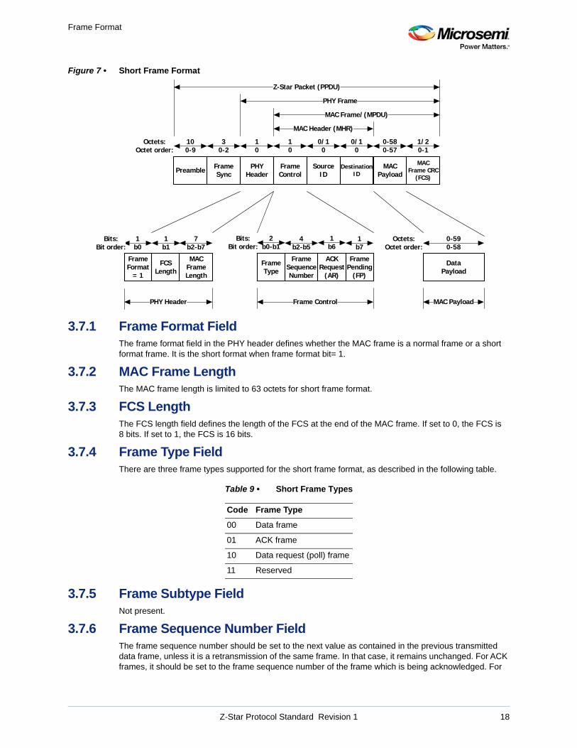
3.7 Short Frame FormatFor reduced overhead, a short frame format may also be used, as shown in the following illustration.
Tx PktsRetries
Last PktRSSI
20-1
Octets:Octet order:
10
NoiseRSSI
10
DroppedTx Pkts
20-1
20-1
CSMARetries
20-1
GoodTx Pkts
GoodRx Pkts
DroppedRx Pkts
CSMAFails
20-1
20-1
20-1
Z-Star Protocol Standard Revision 1 17
Frame Format
Figure 7 • Short Frame Format
3.7.1 Frame Format FieldThe frame format field in the PHY header defines whether the MAC frame is a normal frame or a short format frame. It is the short format when frame format bit= 1.
3.7.2 MAC Frame LengthThe MAC frame length is limited to 63 octets for short frame format.
3.7.3 FCS LengthThe FCS length field defines the length of the FCS at the end of the MAC frame. If set to 0, the FCS is 8 bits. If set to 1, the FCS is 16 bits.
3.7.4 Frame Type FieldThere are three frame types supported for the short frame format, as described in the following table.
3.7.5 Frame Subtype FieldNot present.
3.7.6 Frame Sequence Number FieldThe frame sequence number should be set to the next value as contained in the previous transmitted data frame, unless it is a retransmission of the same frame. In that case, it remains unchanged. For ACK frames, it should be set to the frame sequence number of the frame which is being acknowledged. For
Table 9 • Short Frame Types
Code Frame Type
00 Data frame
01 ACK frame
10 Data request (poll) frame
11 Reserved
FrameControl
SourceID
0/10
Octets:Octet order:
10
DestinationID
0/10
MAC Payload
0-580-57
MAC Frame CRC
(FCS)
1/20-1
ACKRequest
(AR)
FrameType
7b2-b7
1b6
FramePending
(FP)
1b7
FrameFormat
= 1
1b0
PHYHeader
10
MACFrameLength
Bits:Bit order:
2b0-b1
Bits:Bit order:
FrameSequenceNumber
4b2-b5
MAC Header (MHR)
FrameSync
30-2
Preamble
100-9
Z-Star Packet (PPDU)
PHY Frame
PHY Header
MAC Frame/(MPDU)
Data Payload
Octets:Octet order:
MAC PayloadFrame Control
0-590-58
FCSLength
1b1
Z-Star Protocol Standard Revision 1 18
Frame Format
data request frames, it should be set to the next expected frame sequence number. For other frame types, including null data frames, it should be set to 0.
3.7.7 Acknowledgment Request (AR)AR may be set to 1 in a short data frame to request an acknowledgment of the current frame from the recipient.
Note: In an ACK frame, this bit is the Transmit Now (TN) bit.
3.7.8 Transmit Now (TN)— ACK Frame OnlyTN bit is set to 1 in an ACK frame if the hub will be transmitting another frame immediately after transmitting the ACK frame. When set, the receiving device should remain in the receive mode to immediately receive another frame. This bit is in the same location as the AR bit in other frame formats.
3.7.9 Frame Pending (FP)FP set to 1 in a short ACK frame to indicate that a data, command, or admin frame is ready to be sent.
3.7.10 SecuritySecurity is not supported in short frames.
3.7.11 Destination IDThe destination address is only supported in short form in short frames. For short ACK frames, the destination ID is not present (see Figure 8, page 20).
3.7.12 Source IDThe source address is only supported in short form in short frames. For short ACK frames, the destination ID is not present (see Figure 8, page 20).
3.7.13 Network IDNetwork ID is not used in short frames.
3.7.14 MAC PayloadThe MAC payload is limited to 63 octets in short frame format.
3.7.15 MAC Frame CRC FCSThe short format MAC frame contains an 8-bit or 16-bit frame check sequence (FSC), depending on the setting of the FCS length bit in the PHY header. If the FCS length is set to 0, then the FCS is 8 bits. If the FCS length is set to 1, then the FCS is 16 bits. The FCS remainder is initialized to zero in both cases. The FCS is calculated over the entire MAC frame, not including the PHY header.
3.7.15.1 8-bit MAC Frame FCSThe 8-bit FCS calculation is shown in the following equation.
3.7.15.2 16-bit MAC Frame FCSThe 16-bit FCS calculation is shown in the following equation.
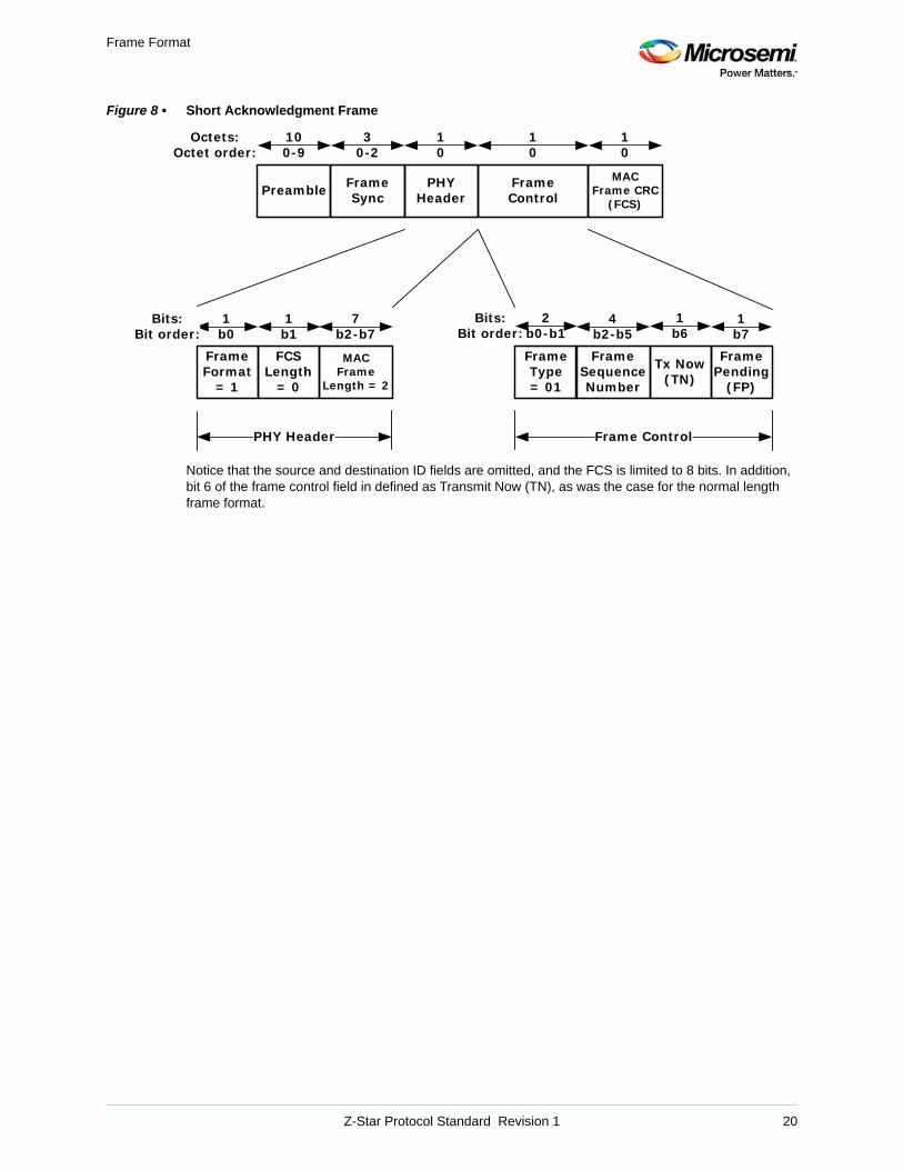
3.7.16 Short Acknowledgment FramesThe following illustration shows the format of the short ACK frame.
FCS x8
x2
x 1+ + +=
FCS x16
x12
x5
1+ + +=
Z-Star Protocol Standard Revision 1 19
Frame Format
Figure 8 • Short Acknowledgment Frame
Notice that the source and destination ID fields are omitted, and the FCS is limited to 8 bits. In addition, bit 6 of the frame control field in defined as Transmit Now (TN), as was the case for the normal length frame format.
FrameControl
Octets:Octet order:
10
MAC Frame CRC
(FCS)
10
Tx Now(TN)
FrameType= 01
7b2-b7
1b6
FramePending
(FP)
1b7
FrameFormat
= 1
1b0
PHYHeader
10
MACFrame
Length = 2
Bits:Bit order:
2b0-b1
Bits:Bit order:
FrameSequenceNumber
4b2-b5
FrameSync
30-2
Preamble
100-9
PHY Header Frame Control
FCSLength
= 0
1b1
Z-Star Protocol Standard Revision 1 20
Frame Processing
4 Frame Processing
4.1 Addressing There are three addresses contained in the MAC header: source ID, destination ID, and network ID. The source ID and destination ID can be of either short (8-bit) form or long (64-bit) form. All devices are assigned a long address at the time of manufacture. At start-up, a hub chooses its hub short ID and possibly a network ID. A hub may only use one hub short ID, but it may use more than one network ID if it is supporting multiple networks or if it has a single network with more than 253 nodes. The nodes are assigned short IDs by the hub during association. However, if there are no more short IDs and only one network ID is used, the node may not receive a short ID and must then use only long addressing.
The network ID may also be used for defining multicast groups, where each network ID defines a multicast group. A node is assigned only one network ID
4.1.1 Short Address AssignmentsA hub shall select a 1-octet integer for its identifier (hub ID), between 0x01 and 0xFE, from the Connected_NID subset as specified in the following table.
The HUD ID may be generated with a random number generator, and should be different from any hub ID observed during the hub's initial channel scan. The hub ID is used as its short address ID in the MAC frame header of all frames sent from or to the hub when short addressing is used.
A hub shall select one or more 1-octet integers for its Network Identifiers (Network IDs), 0x01 through 0xFE, inclusive, which is contained in the MAC frame header of all frames sent. 0x00 and 0xFF are reserved. The network IDs may be generated with a random number generator, and should be different from other network IDs observed during the hub’s initial channel scan.
A 1-octet Identifier (node ID) shall be assigned to each node in accordance with the previous table, and be used as a node's NID address contained in the frame header of all frames sent (unicast) from or to the node.
A 1-octet Network Identifier (Network ID) shall be assigned to each node, between 0x01 and 0xFE, and be used as a node's network ID or local broadcast/multicast ID contained in the frame header of all frames sent from or to the node.
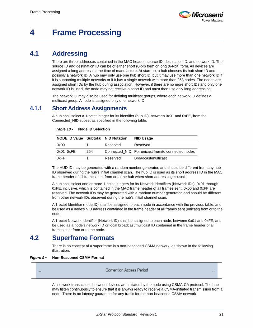
4.2 Superframe FormatsThere is no concept of a superframe in a non-beaconed CSMA network, as shown in the following illustration.
Figure 9 • Non-Beaconed CSMA Format
All network transactions between devices are initiated by the node using CSMA-CA protocol. The hub may listen continuously to ensure that it is always ready to receive a CSMA-initiated transmission from a node. There is no latency guarantee for any traffic for the non-beaconed CSMA network.
Table 10 • Node ID Selection
NODE ID Value Subtotal NID Notation NID Usage
0x00 1 Reserved Reserved
0x01–0xFE 254 Connected_NID For unicast from/to connected nodes
0xFF 1 Reserved Broadcast/multicast
Z-Star Protocol Standard Revision 1 21
Frame Processing
4.3 Channel AccessChannel access is the means by which a device gains access to a frequency channel on the network to initiate a frame transaction on the selected channel. The primary method used to access a channel in a beacon-less, non-superframe network is CSMA-CA. Once channel access is achieved, then a single frame transaction may be performed. To perform a second transaction, another CSMA access must be performed.
Only nodes initiate frame transaction in CSMA channel access, with one exception: if the hub receives a broadcast beacon request frame from a node with the destination address set to 0xFFFFFFFF. In that case, the hub may transmit a beacon frame using a CSMA access. The network ID should be set to 0x00 for broadcast frames.
In networks requiring long ranges with distributed nodes that may not be able to detect valid RSSI levels of other nodes, it is permissible to use ALOHA channel access. In ALOHA channel access, no LBT is required, but if a transmission in unsuccessful, a random back-off is required before another transmission is attempted.
4.4 Frame Transaction TypesA frame transaction consists of the transmission of a data, command, or admin Frame, followed by the reception of an ACK frame, if requested. There are several frame transaction sequences possible.
4.4.1 Single Frame TransactionSingle frame transactions consists of a CSMA operation followed by a signal frame transmission.
4.4.1.1 Broadcast and Multicast FrameBroadcast and multicast frames do not receive an immediate response, and have their AR bit set to 0.
4.4.1.2 Single Data FrameData, command, or admin frames may be transmitted with their AR bit set to 0. In this case, there is no response to the transmission (see Figure 10, page 26).
4.4.2 Data-ACK Frame TransactionMost transactions are of this type. CSMA, followed by a Data, Command, or Admin Frame, with the AR bit set to one, followed by an Acknowledgment Frame (see Figure 15, page 33).
4.4.3 Data-ACK Frame Transaction with a Hub Data TransactionIn a normal data-ACK frame transaction, the hub may set the FP and TN bits in the header of its transmitted ACK frame. In this case, the hub will immediately transmit a data, command, or admin frame, followed by an ACK frame from the node. This forms a 4-frame sequence. The hub may also send the data, command, or admin frame with the AR bit set to 0, in which case the node does not send the ACK (see Figure 18, page 36).
4.4.4 Data Request Frame TransactionIf the hub needs to send a data, command, or admin frame to a node, it must wait for a frame from the node. The hub notifies the node that it has a frame to transmit by setting the FP bit in an acknowledgment frame.
A node will send a data request frame to the hub in two situations. If the node received an ACK frame from hub with the FP bit set to 1 and the TN bit set to 0, then it will initiate a data request sequence with the hub. Second, if the time between transactions has exceeded aTimeDataPoll, the node will initiate a data request sequence.
In this frame transaction, the transaction consists of a data request frame, followed by the data, command, or admin frame, followed by an ACK frame if requested (see Figure 19, page 37).
4.5 Frame ReceptionFrame reception defines the conditions under which a frame is classified as “received.”
Z-Star Protocol Standard Revision 1 22
Frame Processing
4.5.1 Frame Reception by the HubA hub shall “receive” a frame if the following conditions are met by the received frame:
• The destination ID is set to its own short HID or its long address, or to the long broadcast address 0xFFFFFFFF.
• The source ID is set to the short NID or long address of an expected sender. The hub has to option of ignoring the source ID for packet reception qualification. The source ID is ignored for broadcast frames.
• The network ID is set to the assigned network ID assigned to the node by the hub. For broadcast frames, it may be 0x00. The hub may ignore some or all bits in the network ID if the hub has assigned multiple network IDs to the nodes. In long addressing mode, it is ignored.
• The frame type and subtype fields contain valid frame types and frame subtypes.• The FCS of the frame is valid— that is, equal to the FCS value it calculates over the entire MAC
frame, including FCS.
A frame may only be acknowledged if it meets the frame reception requirements. The hub shall ignore a “received” frame, aside from performing applicable acknowledgment, if it is detected to be a duplicate (as described in Frame Sequence Number Field, page 18).
4.5.2 Frame Reception by a NodeA node shall “receive” a frame if the following conditions are met in the received frame:
• The destination ID field is set to its own short NID or long address. For short broadcast or multicast, the NID is set to 0xFF.
• The source ID field is set to the short HID or long address of the hub. Before the hub accepts and responds to an association request, the source address is ignored.
• The network ID is set to the assigned network ID in short addressing. In long addressing, it is ignored.
• The frame type and subtype fields contain valid frame types and frame subtypes.• The FCS of the frame is valid— that is, equal to the FCS value it calculates over the applicable fields
received.
A frame may only be acknowledged if it meets the frame reception requirements. The node shall ignore a received frame, aside from performing applicable acknowledgment, if it is detected to be a duplicate (as described in Frame Sequence Number Field, page 18).
4.6 Acknowledging a FrameThe sender of a data, command, or admin frame shall set the acknowledge request bit (AR) to the desired response from the recipient. When AR=1, the recipient shall immediately respond to the received frame by transmitting an ACK frame, provided that the frame reception requirements are met.
4.7 Starting a NetworkA hub must find an appropriate channel and generate a channel table (future) in order to begin a network. A hub should have a channel list of all optional channels available for its use, listed in the order of preference. The hub scans and measures RSSI on the selected channels (all, or the first set) in the channel list and then starts the network on the selected channel. Once the channel is selected, the hub stays in receive to listen for beacon request and association request commands from the nodes wishing to join the network. Once a node is associated, then the hub also listens for data, command, and admin frames from the connected node.
4.7.1 Channel ListThe hub and each unassociated node must contain a channel list in its NV memory. The list is ordered by preferred channel number so that it will allow the node to find a hub in the least probable number of channel scans. The nodes must also contain their MAC long address in their NV memory for use in the association process.
Z-Star Protocol Standard Revision 1 23
Frame Processing
4.7.2 Channel TableAfter the hub performs the channel scan from the channel list, it builds an ordered list of good channels from which to select in case the current channel becomes too noisy or unavailable. This list is the channel table, which is sent to all nodes in case they are unable to receive the channel change command.
Z-Star Protocol Standard Revision 1 24
Frame Transactions
5 Frame Transactions
5.1 Beacon Request and TransmissionThe node selects a channel from its channel list, or from the channel table if it was received. The node performs CSMA to access the channel and then sends a beacon request frame using the CSMA retry counts. This process is repeated for different channels until a beacon frame is received. When beacons are sent by the hub, a CSMA access is required by the hub because of the broadcast nature of the beacon request.
The following illustration shows the beacon request and transmission.
Z-Star Protocol Standard Revision 1 25
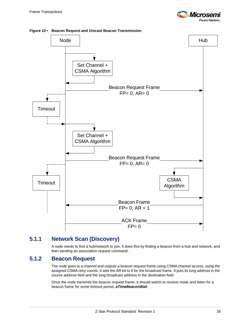
Frame Transactions
Figure 10 • Beacon Request and Unicast Beacon Transmission
5.1.1 Network Scan (Discovery)A node needs to find a hub/network to join. It does this by finding a beacon from a hub and network, and then sending an association request command.
5.1.2 Beacon RequestThe node goes to a channel and outputs a beacon request frame using CSMA channel access, using the assigned CSMA retry counts. It sets the AR bit to 0 for the broadcast frame. It puts its long address in the source address field and the long broadcast address in the destination field.
Once the node transmits the beacon request frame, it should switch to receive mode and listen for a beacon frame for some timeout period, aTimeBeaconWait.
Node Hub
Set Channel +CSMA Algorithm
Beacon Request FrameFP= 0, AR= 0
Beacon FrameFP= 0, AR = 1
Timeout
Beacon Request FrameFP= 0, AR= 0
Set Channel +CSMA Algorithm
CSMA Algorithm
Timeout
ACK FrameFP= 0
Z-Star Protocol Standard Revision 1 26
Frame Transactions
Because the beacon request is a broadcast command, the node may receive more than one beacon frame from different hubs that are accessing the channel with CSMA access. Once it receives a beacon frame from one hub, it may be necessary to listen for beacon frames from other hubs in the area using additional aTimeBeaconWait periods. It should wait long enough to receive all beacon frames.
If no hubs respond to the beacon request on that channel, the node goes to the next channel and transmits another beacon request.
Beacon frames are typically sent unicast to the requesting node with the AR bit set. This means that the node shall acknowledge the beacon using long addressing.
If the node knows the long address of the hub, then it may skip the beacon request frame and go directly to association request.
The format of the beacon request frame is the same as the ACK frame with the following exceptions:
5.1.3 Beacon TransmissionWhen a hub receives a beacon request, it immediately sends a beacon frame in response using a CSMA access, with its long address in the source field and the long broadcast address or the node's long address in the destination field. If it uses the node's long address for the destination, then it may set the Acknowledge Request (AR) bit in the MAC header. For cases when many nodes may be requesting beacons, it is best to use broadcast mode for the beacon transmission.
If the hub does not receive an acknowledgment back from the node addressed in the beacon when the AR bit is set, then it should retransmit the beacon after performing another CSMA, if enabled, for the programmed retry count.
5.1.4 Beacon ReceptionWhen the node receives a beacon, it checks the hub address to validate that the beacon is from an acceptable hub. If the beacon is addressed to the node and the AR bit is set, then the node should send an acknowledgment packet to the hub. To receive the beacon, the node should ignore the source and network IDs on reception unless it knows the source of the hub to which it wants to connect.
5.2 AssociationOnce a node finds an acceptable hub/Network, it will attempt to join the network.
5.2.1 Association RequestAfter receiving a beacon and finding a hub, the node transmits an association request command frame using long addressing mode. This is accompanied by its long address in the MAC header, and possibly some additional payload information for the authentication. After receiving an ACK, it waits for aTimeAssocReq before sending a data request frame to the node.
5.2.2 Authentication (Pairing Authorization)When the hub receives the association request, it acknowledges the frame using long addressing mode and passes the request to the network or application layer. At that level, the association request is either approved or rejected. This is also known as pairing authorization or authentication. There are several methods for performing the pairing authorization, so it is application specific and beyond the scope of the MAC protocol.
5.2.2.1 Manual Approval OptionThe request is displayed along with specified information such as device type and serial number, and the user either rejects or accepts the request.
5.2.2.2 Approval based on Node's Long Address OptionA list of approved nodes based on long address is maintained at the authentication layer. If the address matches, then the request is accepted.
Z-Star Protocol Standard Revision 1 27
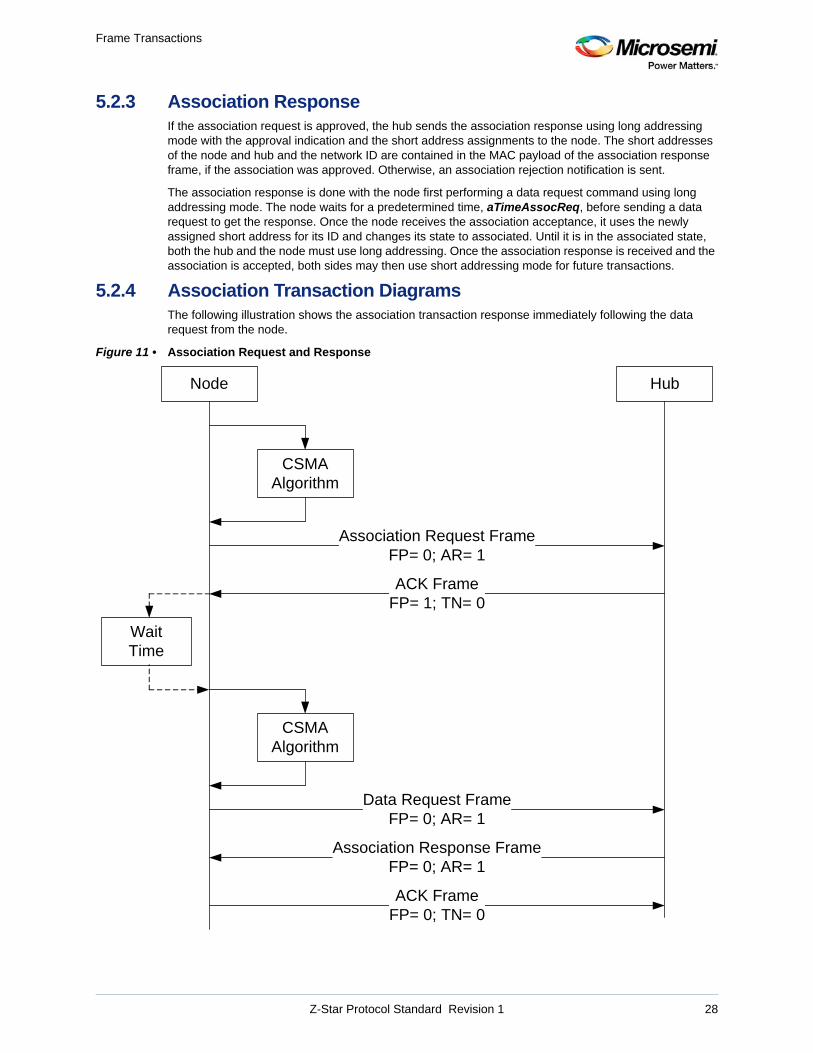
Frame Transactions
5.2.3 Association ResponseIf the association request is approved, the hub sends the association response using long addressing mode with the approval indication and the short address assignments to the node. The short addresses of the node and hub and the network ID are contained in the MAC payload of the association response frame, if the association was approved. Otherwise, an association rejection notification is sent.
The association response is done with the node first performing a data request command using long addressing mode. The node waits for a predetermined time, aTimeAssocReq, before sending a data request to get the response. Once the node receives the association acceptance, it uses the newly assigned short address for its ID and changes its state to associated. Until it is in the associated state, both the hub and the node must use long addressing. Once the association response is received and the association is accepted, both sides may then use short addressing mode for future transactions.
5.2.4 Association Transaction DiagramsThe following illustration shows the association transaction response immediately following the data request from the node.
Figure 11 • Association Request and Response
Node Hub
CSMAAlgorithm
Association Request FrameFP= 0; AR= 1
ACK FrameFP= 1; TN= 0
Association Response FrameFP= 0; AR= 1
ACK FrameFP= 0; TN= 0
WaitTime
Data Request FrameFP= 0; AR= 1
CSMAAlgorithm
Z-Star Protocol Standard Revision 1 28

Frame Transactions
The wait time, aTimeAssocReq, is a parameter that is set in the NV memory tables. If the hub is not ready when the data request is sent, then the hub should respond with a null data frame with the FP bit set to 1 and AR bit set to 0. Then, the node should retry after another aTimeAssocReq interval. This is shown in the following illustration.
Z-Star Protocol Standard Revision 1 29
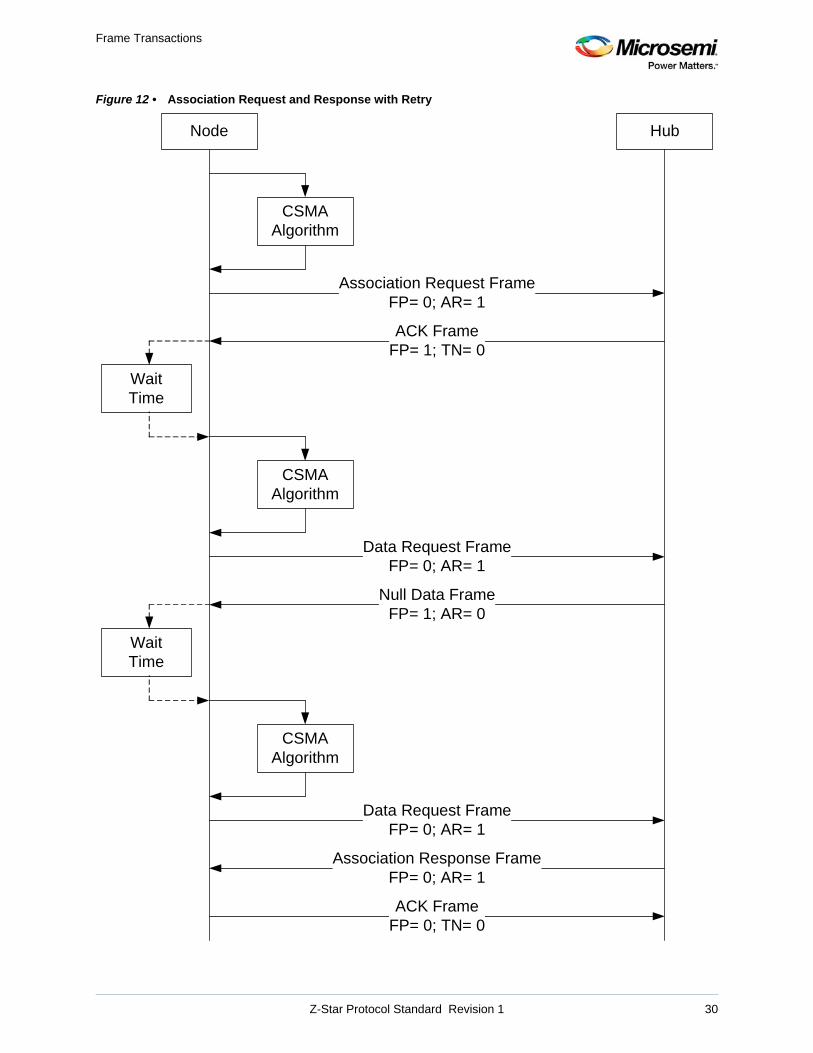
Frame Transactions
Figure 12 • Association Request and Response with Retry
Node Hub
CSMAAlgorithm
Association Request FrameFP= 0; AR= 1
ACK FrameFP= 1; TN= 0
WaitTime
Data Request FrameFP= 0; AR= 1
CSMAAlgorithm
Association Response FrameFP= 0; AR= 1
ACK FrameFP= 0; TN= 0
WaitTime
Data Request FrameFP= 0; AR= 1
CSMAAlgorithm
Null Data FrameFP= 1; AR= 0
Z-Star Protocol Standard Revision 1 30
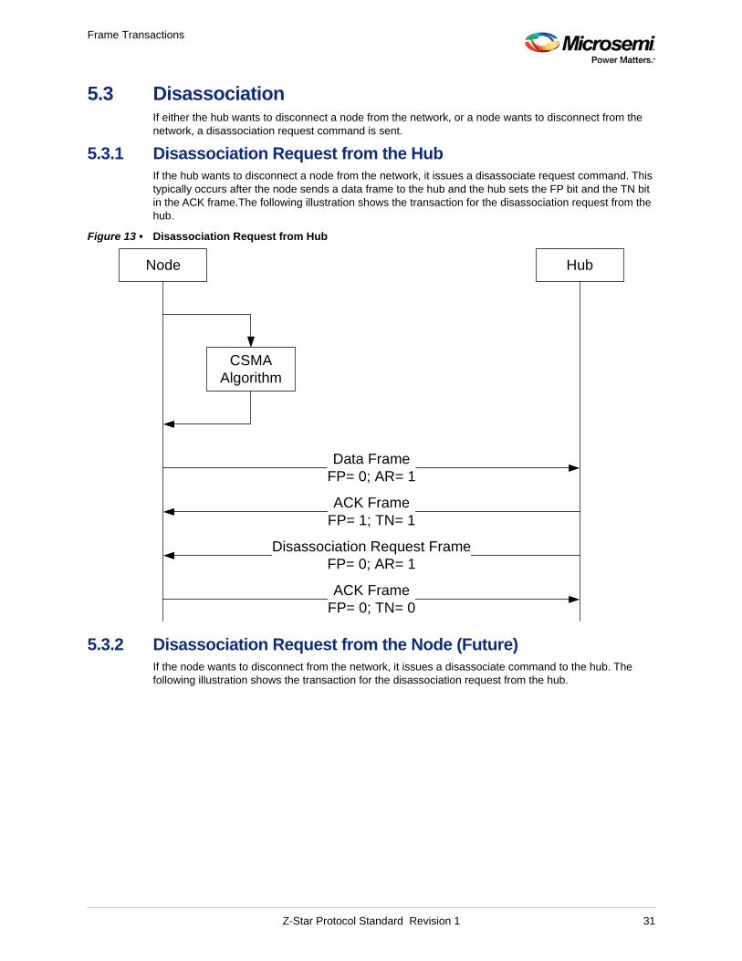
Frame Transactions
5.3 DisassociationIf either the hub wants to disconnect a node from the network, or a node wants to disconnect from the network, a disassociation request command is sent.
5.3.1 Disassociation Request from the HubIf the hub wants to disconnect a node from the network, it issues a disassociate request command. This typically occurs after the node sends a data frame to the hub and the hub sets the FP bit and the TN bit in the ACK frame.The following illustration shows the transaction for the disassociation request from the hub.
Figure 13 • Disassociation Request from Hub
5.3.2 Disassociation Request from the Node (Future)If the node wants to disconnect from the network, it issues a disassociate command to the hub. The following illustration shows the transaction for the disassociation request from the hub.
Node Hub
CSMAAlgorithm
ACK FrameFP= 1; TN= 1
Data FrameFP= 0; AR= 1
Disassociation Request FrameFP= 0; AR= 1
ACK FrameFP= 0; TN= 0
Z-Star Protocol Standard Revision 1 31
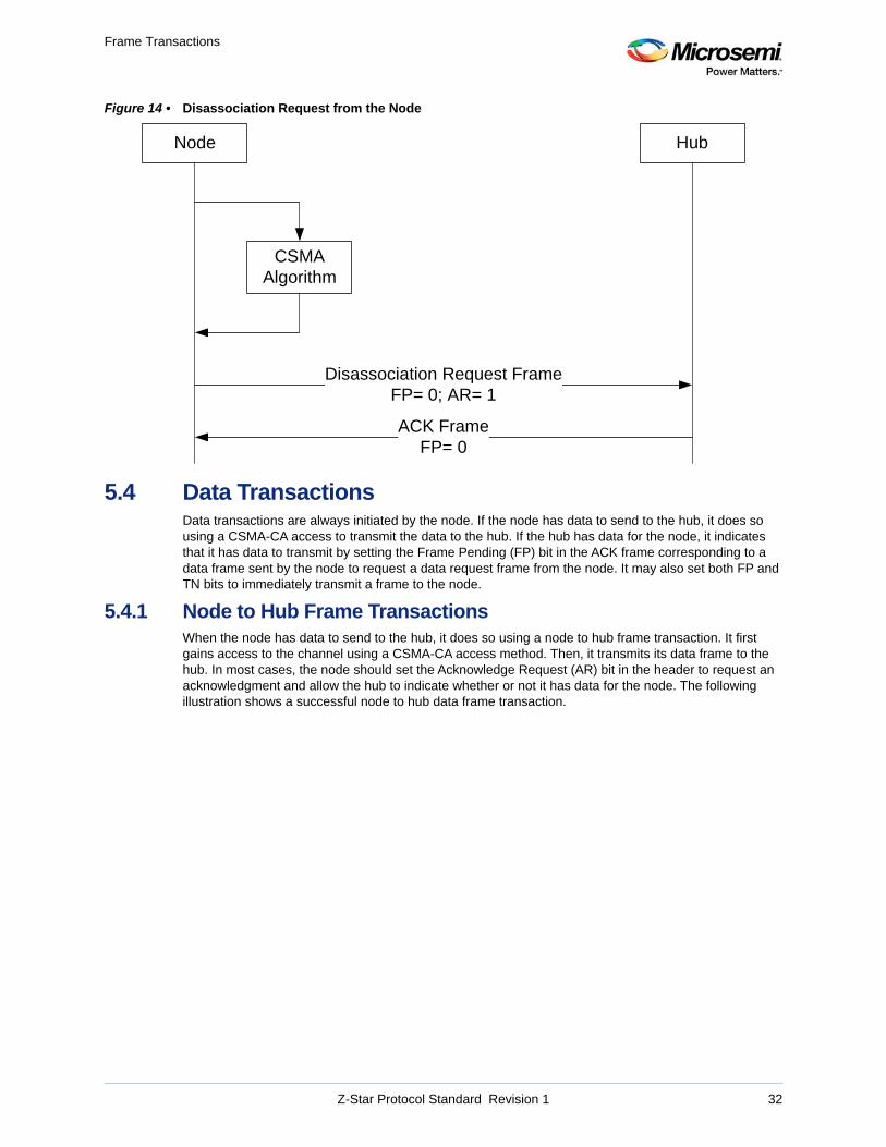
Frame Transactions
Figure 14 • Disassociation Request from the Node
5.4 Data TransactionsData transactions are always initiated by the node. If the node has data to send to the hub, it does so using a CSMA-CA access to transmit the data to the hub. If the hub has data for the node, it indicates that it has data to transmit by setting the Frame Pending (FP) bit in the ACK frame corresponding to a data frame sent by the node to request a data request frame from the node. It may also set both FP and TN bits to immediately transmit a frame to the node.
5.4.1 Node to Hub Frame TransactionsWhen the node has data to send to the hub, it does so using a node to hub frame transaction. It first gains access to the channel using a CSMA-CA access method. Then, it transmits its data frame to the hub. In most cases, the node should set the Acknowledge Request (AR) bit in the header to request an acknowledgment and allow the hub to indicate whether or not it has data for the node. The following illustration shows a successful node to hub data frame transaction.
Node Hub
CSMAAlgorithm
ACK FrameFP= 0
Disassociation Request FrameFP= 0; AR= 1
Z-Star Protocol Standard Revision 1 32
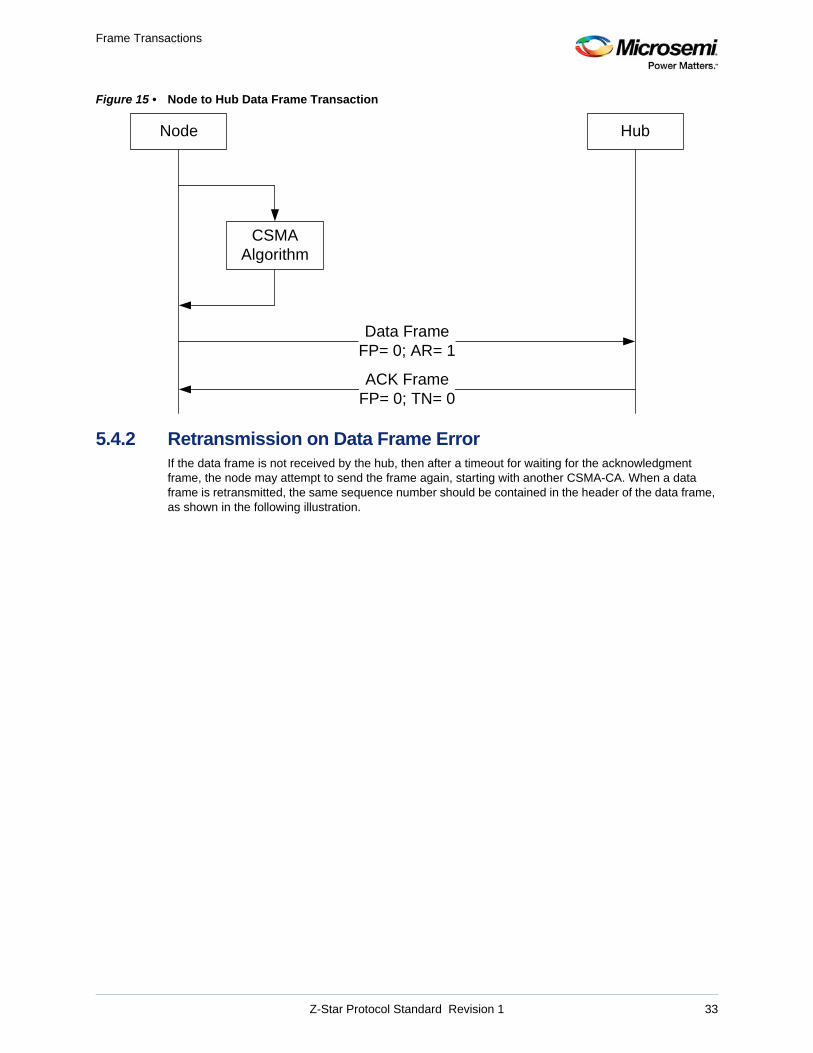
Frame Transactions
Figure 15 • Node to Hub Data Frame Transaction
5.4.2 Retransmission on Data Frame ErrorIf the data frame is not received by the hub, then after a timeout for waiting for the acknowledgment frame, the node may attempt to send the frame again, starting with another CSMA-CA. When a data frame is retransmitted, the same sequence number should be contained in the header of the data frame, as shown in the following illustration.
Node Hub
CSMAAlgorithm
ACK FrameFP= 0; TN= 0
Data FrameFP= 0; AR= 1
Z-Star Protocol Standard Revision 1 33
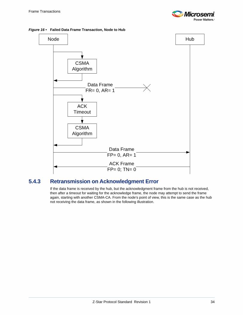
Frame Transactions
Figure 16 • Failed Data Frame Transaction, Node to Hub
5.4.3 Retransmission on Acknowledgment ErrorIf the data frame is received by the hub, but the acknowledgment frame from the hub is not received, then after a timeout for waiting for the acknowledge frame, the node may attempt to send the frame again, starting with another CSMA-CA. From the node's point of view, this is the same case as the hub not receiving the data frame, as shown in the following illustration.
Node Hub
CSMAAlgorithm
ACK FrameFP= 0; TN= 0
Data FrameFR= 0, AR= 1
ACKTimeout
CSMAAlgorithm
Data FrameFP= 0, AR= 1
Z-Star Protocol Standard Revision 1 34
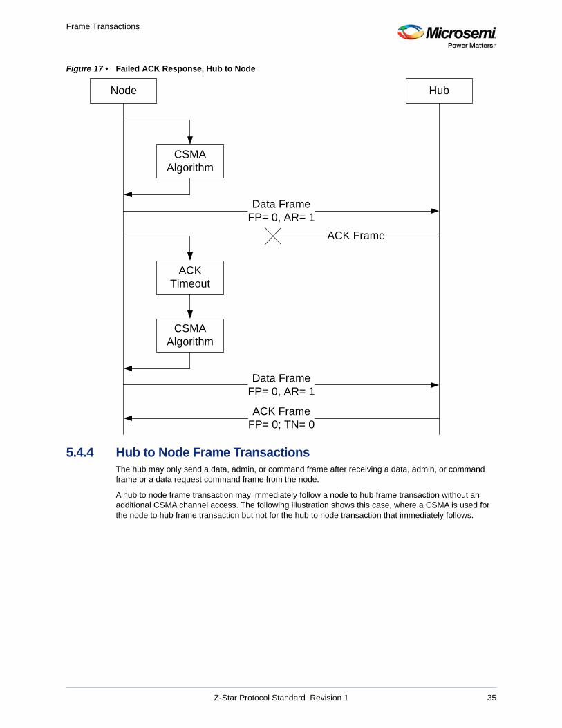
Frame Transactions
Figure 17 • Failed ACK Response, Hub to Node
5.4.4 Hub to Node Frame TransactionsThe hub may only send a data, admin, or command frame after receiving a data, admin, or command frame or a data request command frame from the node.
A hub to node frame transaction may immediately follow a node to hub frame transaction without an additional CSMA channel access. The following illustration shows this case, where a CSMA is used for the node to hub frame transaction but not for the hub to node transaction that immediately follows.
Node Hub
CSMAAlgorithm
ACKTimeout
CSMAAlgorithm
Data FrameFP= 0, AR= 1
Data FrameFP= 0, AR= 1
ACK Frame
ACK FrameFP= 0; TN= 0
Z-Star Protocol Standard Revision 1 35
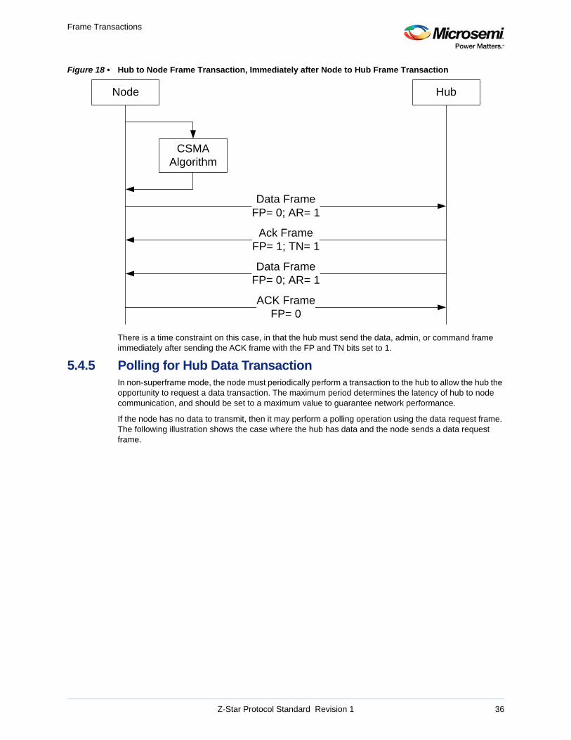
Frame Transactions
Figure 18 • Hub to Node Frame Transaction, Immediately after Node to Hub Frame Transaction
There is a time constraint on this case, in that the hub must send the data, admin, or command frame immediately after sending the ACK frame with the FP and TN bits set to 1.
5.4.5 Polling for Hub Data TransactionIn non-superframe mode, the node must periodically perform a transaction to the hub to allow the hub the opportunity to request a data transaction. The maximum period determines the latency of hub to node communication, and should be set to a maximum value to guarantee network performance.
If the node has no data to transmit, then it may perform a polling operation using the data request frame. The following illustration shows the case where the hub has data and the node sends a data request frame.
Node Hub
CSMAAlgorithm
Ack FrameFP= 1; TN= 1
Data FrameFP= 0; AR= 1
Data FrameFP= 0; AR= 1
ACK FrameFP= 0
Z-Star Protocol Standard Revision 1 36
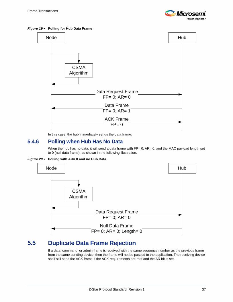
Frame Transactions
Figure 19 • Polling for Hub Data Frame
In this case, the hub immediately sends the data frame.
5.4.6 Polling when Hub Has No DataWhen the hub has no data, it will send a data frame with FP= 0, AR= 0, and the MAC payload length set to 0 (null data frame), as shown in the following illustration.
Figure 20 • Polling with AR= 0 and no Hub Data
5.5 Duplicate Data Frame RejectionIf a data, command, or admin frame is received with the same sequence number as the previous frame from the same sending device, then the frame will not be passed to the application. The receiving device shall still send the ACK frame if the ACK requirements are met and the AR bit is set.
Node Hub
CSMAAlgorithm
Data Request FrameFP= 0; AR= 0
Data FrameFP= 0; AR= 1
ACK FrameFP= 0
Node Hub
CSMAAlgorithm
Data Request FrameFP= 0; AR= 0
Null Data FrameFP= 0; AR= 0; Length= 0
Z-Star Protocol Standard Revision 1 37
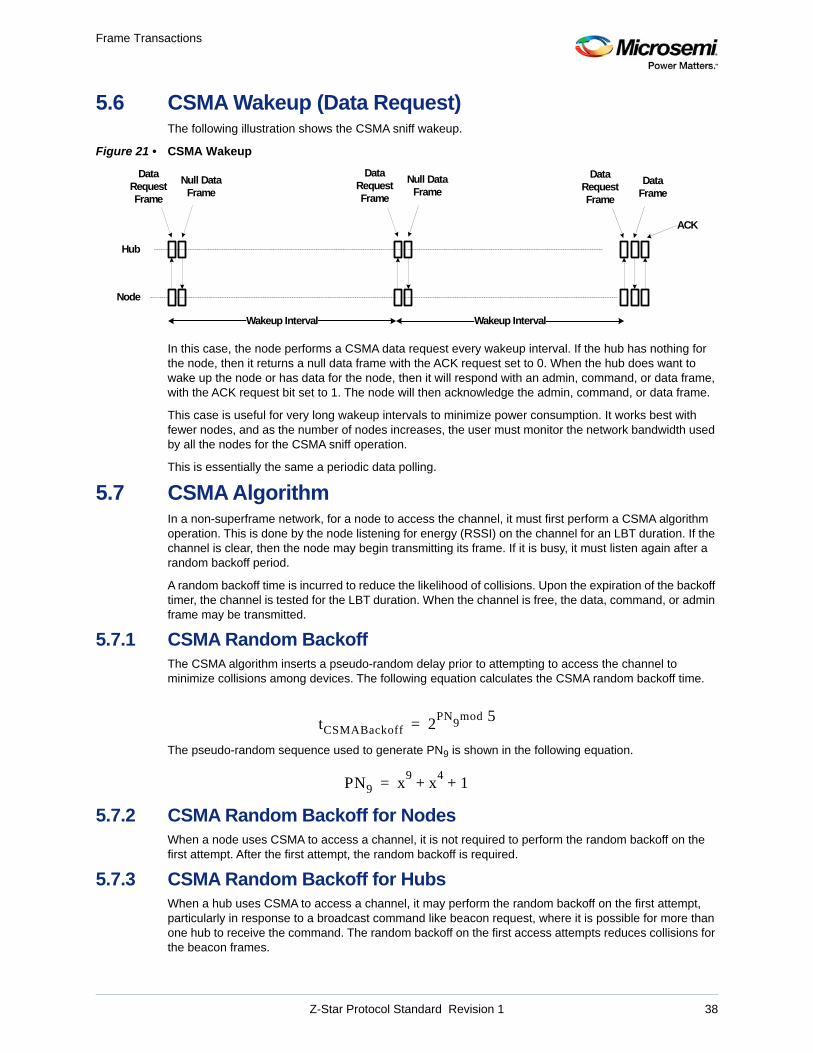
Frame Transactions
5.6 CSMA Wakeup (Data Request)The following illustration shows the CSMA sniff wakeup.
Figure 21 • CSMA Wakeup
In this case, the node performs a CSMA data request every wakeup interval. If the hub has nothing for the node, then it returns a null data frame with the ACK request set to 0. When the hub does want to wake up the node or has data for the node, then it will respond with an admin, command, or data frame, with the ACK request bit set to 1. The node will then acknowledge the admin, command, or data frame.
This case is useful for very long wakeup intervals to minimize power consumption. It works best with fewer nodes, and as the number of nodes increases, the user must monitor the network bandwidth used by all the nodes for the CSMA sniff operation.
This is essentially the same a periodic data polling.
5.7 CSMA AlgorithmIn a non-superframe network, for a node to access the channel, it must first perform a CSMA algorithm operation. This is done by the node listening for energy (RSSI) on the channel for an LBT duration. If the channel is clear, then the node may begin transmitting its frame. If it is busy, it must listen again after a random backoff period.
A random backoff time is incurred to reduce the likelihood of collisions. Upon the expiration of the backoff timer, the channel is tested for the LBT duration. When the channel is free, the data, command, or admin frame may be transmitted.
5.7.1 CSMA Random BackoffThe CSMA algorithm inserts a pseudo-random delay prior to attempting to access the channel to minimize collisions among devices. The following equation calculates the CSMA random backoff time.
The pseudo-random sequence used to generate PN9 is shown in the following equation.
5.7.2 CSMA Random Backoff for NodesWhen a node uses CSMA to access a channel, it is not required to perform the random backoff on the first attempt. After the first attempt, the random backoff is required.
5.7.3 CSMA Random Backoff for HubsWhen a hub uses CSMA to access a channel, it may perform the random backoff on the first attempt, particularly in response to a broadcast command like beacon request, where it is possible for more than one hub to receive the command. The random backoff on the first access attempts reduces collisions for the beacon frames.
Wakeup Interval
Node
Hub
Wakeup Interval
DataRequestFrame
Null DataFrame
DataRequestFrame
Null DataFrame
DataRequestFrame
DataFrame
ACK
tCSMABackoff 2PN
9mod 5=
PN9 x9
x4
1+ +=
Z-Star Protocol Standard Revision 1 38
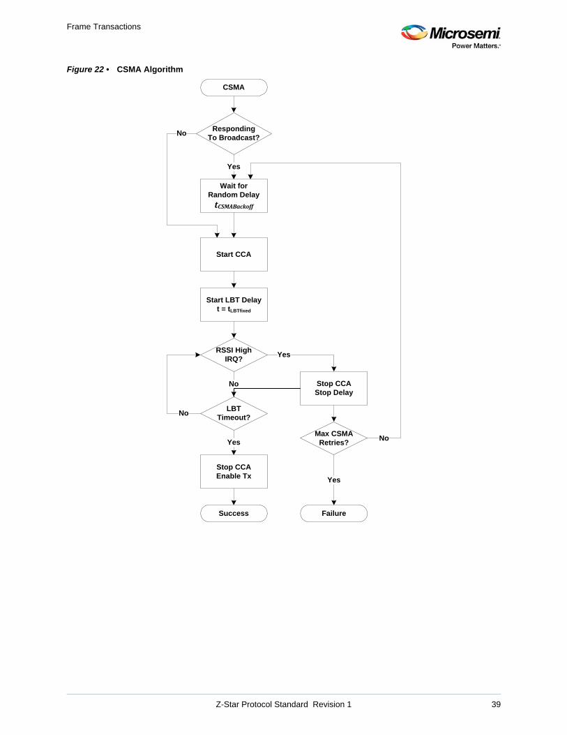
Frame Transactions
Figure 22 • CSMA Algorithm
CSMA
Start CCA
Start LBT Delayt = tLBTfixed
RSSI HighIRQ?
No
LBT Timeout?
Yes
Stop CCAStop Delay
Stop CCAEnable Tx
Success
Yes
Failure
No
Max CSMARetries?
Yes
No
RespondingTo Broadcast?
Wait forRandom Delay
tCSMABackoff
Yes
No
Z-Star Protocol Standard Revision 1 39
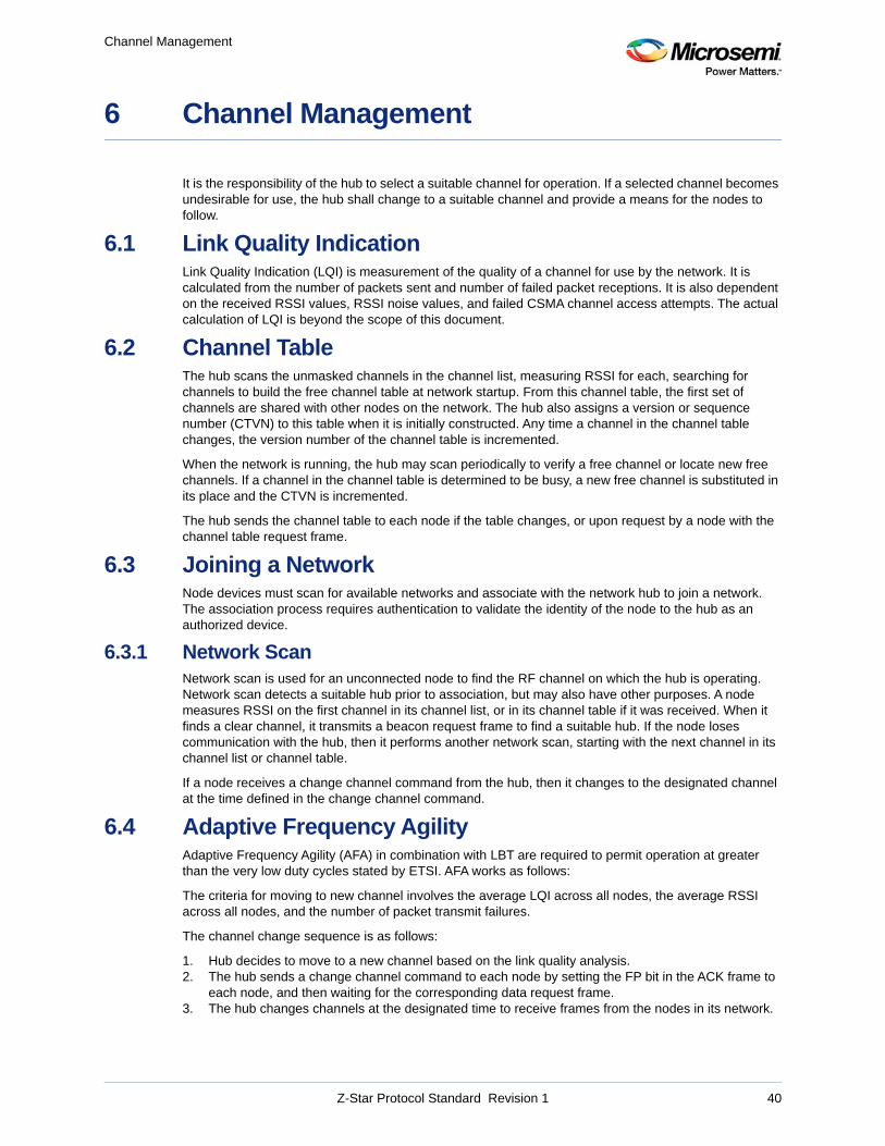
Channel Management
6 Channel Management
It is the responsibility of the hub to select a suitable channel for operation. If a selected channel becomes undesirable for use, the hub shall change to a suitable channel and provide a means for the nodes to follow.
6.1 Link Quality IndicationLink Quality Indication (LQI) is measurement of the quality of a channel for use by the network. It is calculated from the number of packets sent and number of failed packet receptions. It is also dependent on the received RSSI values, RSSI noise values, and failed CSMA channel access attempts. The actual calculation of LQI is beyond the scope of this document.
6.2 Channel TableThe hub scans the unmasked channels in the channel list, measuring RSSI for each, searching for channels to build the free channel table at network startup. From this channel table, the first set of channels are shared with other nodes on the network. The hub also assigns a version or sequence number (CTVN) to this table when it is initially constructed. Any time a channel in the channel table changes, the version number of the channel table is incremented.
When the network is running, the hub may scan periodically to verify a free channel or locate new free channels. If a channel in the channel table is determined to be busy, a new free channel is substituted in its place and the CTVN is incremented.
The hub sends the channel table to each node if the table changes, or upon request by a node with the channel table request frame.
6.3 Joining a NetworkNode devices must scan for available networks and associate with the network hub to join a network. The association process requires authentication to validate the identity of the node to the hub as an authorized device.
6.3.1 Network ScanNetwork scan is used for an unconnected node to find the RF channel on which the hub is operating. Network scan detects a suitable hub prior to association, but may also have other purposes. A node measures RSSI on the first channel in its channel list, or in its channel table if it was received. When it finds a clear channel, it transmits a beacon request frame to find a suitable hub. If the node loses communication with the hub, then it performs another network scan, starting with the next channel in its channel list or channel table.
If a node receives a change channel command from the hub, then it changes to the designated channel at the time defined in the change channel command.
6.4 Adaptive Frequency AgilityAdaptive Frequency Agility (AFA) in combination with LBT are required to permit operation at greater than the very low duty cycles stated by ETSI. AFA works as follows:
The criteria for moving to new channel involves the average LQI across all nodes, the average RSSI across all nodes, and the number of packet transmit failures.
The channel change sequence is as follows:
1. Hub decides to move to a new channel based on the link quality analysis.2. The hub sends a change channel command to each node by setting the FP bit in the ACK frame to
each node, and then waiting for the corresponding data request frame.3. The hub changes channels at the designated time to receive frames from the nodes in its network.
Z-Star Protocol Standard Revision 1 40
Channel Management
4. Each node changes channels at the designated time, and from that point in time, performs all channel access and frame transactions on the new channel.
Nodes unaware of the channel change will need to attempt to find the hub on the next channel in their channel table. The node attempts communication on each channel in the channel table until the hub responds or the node times out. At timeout, the node attempts to search on the next channel until the network hub is found or the network scan timeout expires.
The hub invokes a reconnect timer that is the amount of time nodes have to communicate to the hub after an AFA channel change. Any nodes not reconnected at the expiration of this timer are removed from the hub's association table and are required to re-associate to the network. If a node attempts a communication when it is not in the hub's association table, the hub will not respond to it, except for association requests using long addressing.
Note: This requires the hub to qualify the node's short NID before sending an ACK.
The minimum time the hub spends on a channel is configurable. This timer will limit the rate of change in changing channels and prevent chattering. The minimum time should be longer than is required for most nodes to find and reconnect to the hub.
Z-Star Protocol Standard Revision 1 41
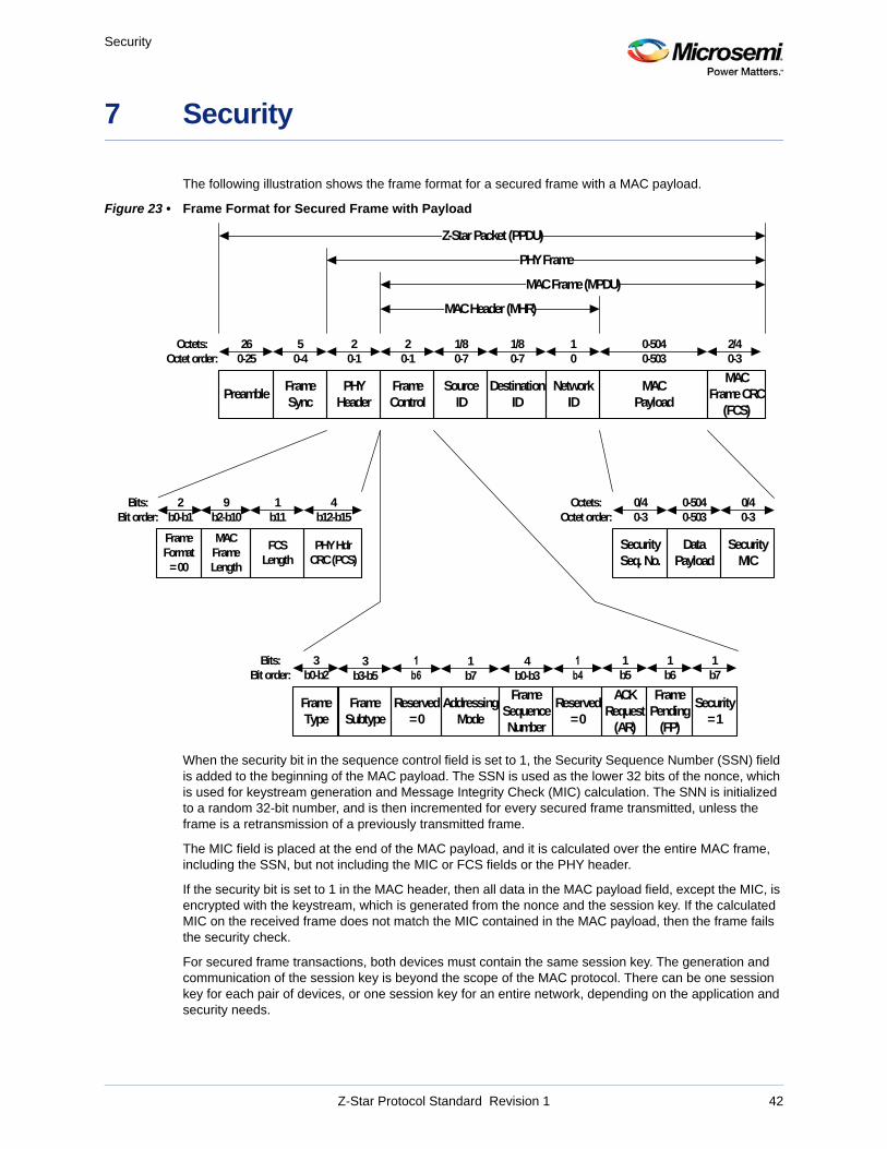
Security
7 Security
The following illustration shows the frame format for a secured frame with a MAC payload.
Figure 23 • Frame Format for Secured Frame with Payload
When the security bit in the sequence control field is set to 1, the Security Sequence Number (SSN) field is added to the beginning of the MAC payload. The SSN is used as the lower 32 bits of the nonce, which is used for keystream generation and Message Integrity Check (MIC) calculation. The SNN is initialized to a random 32-bit number, and is then incremented for every secured frame transmitted, unless the frame is a retransmission of a previously transmitted frame.
The MIC field is placed at the end of the MAC payload, and it is calculated over the entire MAC frame, including the SSN, but not including the MIC or FCS fields or the PHY header.
If the security bit is set to 1 in the MAC header, then all data in the MAC payload field, except the MIC, is encrypted with the keystream, which is generated from the nonce and the session key. If the calculated MIC on the received frame does not match the MIC contained in the MAC payload, then the frame fails the security check.
For secured frame transactions, both devices must contain the same session key. The generation and communication of the session key is beyond the scope of the MAC protocol. There can be one session key for each pair of devices, or one session key for an entire network, depending on the application and security needs.
FrameControl
NetworkID
SourceID
1/80-7
10
Octets:Octet order:
20-1
DestinationID
1/80-7
MAC Payload
0-5040-503
MAC Frame CRC
(FCS)
2/40-3
FramePending
(FP)
Reserved= 0
FrameType
1b5
ACKRequest
(AR)
1b6
AddressingMode
1b7
PHYHeader
20-1
Bits:Bit order:
3b0-b2
FrameSequenceNumber
4b0-b3
Security= 1
FrameSubtype
3b3-b5
Reserved= 0
1b7
MAC Header (MHR)
FrameSync
50-4
Preamble
260-25
Z-Star Packet (PPDU)
PHY Frame
MAC Frame (MPDU)
Data Payload
0-5040-503
SecurityMIC
0/40-3
Octets:Octet order:
SecuritySeq. No.
0/40-3
4b12-b15
MACFrameLength
9b2-b10
PHY Hdr CRC (PCS)
Bits:Bit order:
FCSLength
1b11
FrameFormat= 00
2b0-b1
Z-Star Protocol Standard Revision 1 42

Security
Frames with no MAC payload, such as ACK Frames, are not secured. There must be payload data contained in the frame for the frame to be transmitted in secure mode.
Secured frame transactions may not use short addressing mode.
Z-Star Protocol Standard Revision 1 43