Embed Size (px)
Citation preview
800-543-9038 USA 866-805-7089 CANADA 203-791-8396 LATIN AMERICA
1
ZG-JSL, ZG-JSLA Jackshaft Retrofi t LinkageFor AF, NF, LF, NMX and AMX Series Actuators
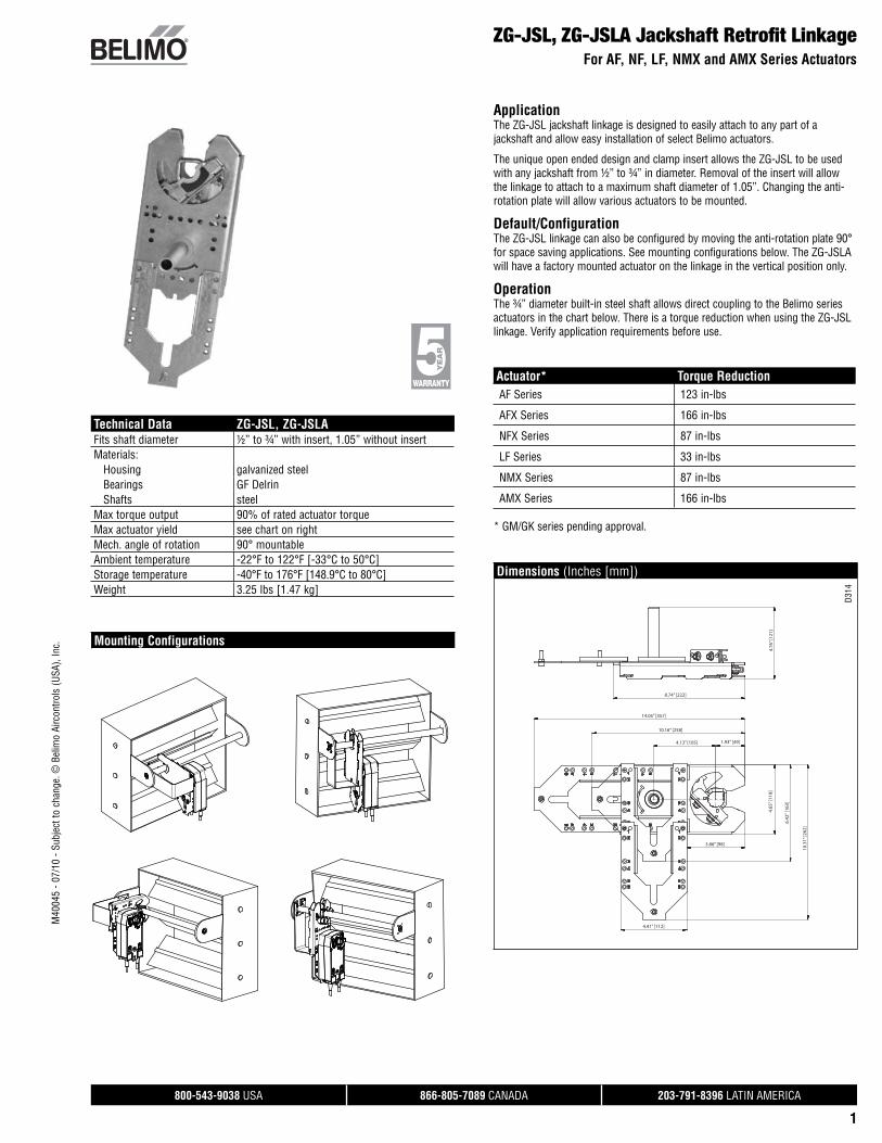
ApplicationThe ZG-JSL jackshaft linkage is designed to easily attach to any part of a jackshaft and allow easy installation of select Belimo actuators.
The unique open ended design and clamp insert allows the ZG-JSL to be used with any jackshaft from ½” to ¾” in diameter. Removal of the insert will allow the linkage to attach to a maximum shaft diameter of 1.05”. Changing the anti-rotation plate will allow various actuators to be mounted.
Default/ConfigurationThe ZG-JSL linkage can also be configured by moving the anti-rotation plate 90° for space saving applications. See mounting configurations below. The ZG-JSLA will have a factory mounted actuator on the linkage in the vertical position only.
OperationThe ¾” diameter built-in steel shaft allows direct coupling to the Belimo series actuators in the chart below. There is a torque reduction when using the ZG-JSL linkage. Verify application requirements before use.
Actuator* Torque ReductionAF Series 123 in-lbs
AFX Series 166 in-lbs
NFX Series 87 in-lbs
LF Series 33 in-lbs
NMX Series 87 in-lbs
AMX Series 166 in-lbs
* GM/GK series pending approval.
Dimensions (Inches [mm])
4.76
” [12
1]
8.74” [222]
14.05” [357]
10.16” [258]
4.13” [105] 1.93” [49]
3.86” [98]
4.41” [112]
4.65
” [11
8]
6.42
” [16
3]
10.3
1” [2
62]
D314
Technical Data ZG-JSL, ZG-JSLAFits shaft diameter ½” to ¾” with insert, 1.05” without insertMaterials: Housing galvanized steel Bearings GF Delrin Shafts steelMax torque output 90% of rated actuator torqueMax actuator yield see chart on rightMech. angle of rotation 90° mountableAmbient temperature -22°F to 122°F [-33°C to 50°C]Storage temperature -40°F to 176°F [148.9°C to 80°C]Weight 3.25 lbs [1.47 kg]
Mounting Configurations
M40
045
- 07/
10 -
Subj
ect t
o ch
ange
. © B
elim
o Ai
rcon
trols
(USA
), In
c.
800-543-9038 USA 866-805-7089 CANADA 203-791-8396 LATIN AMERICA
19
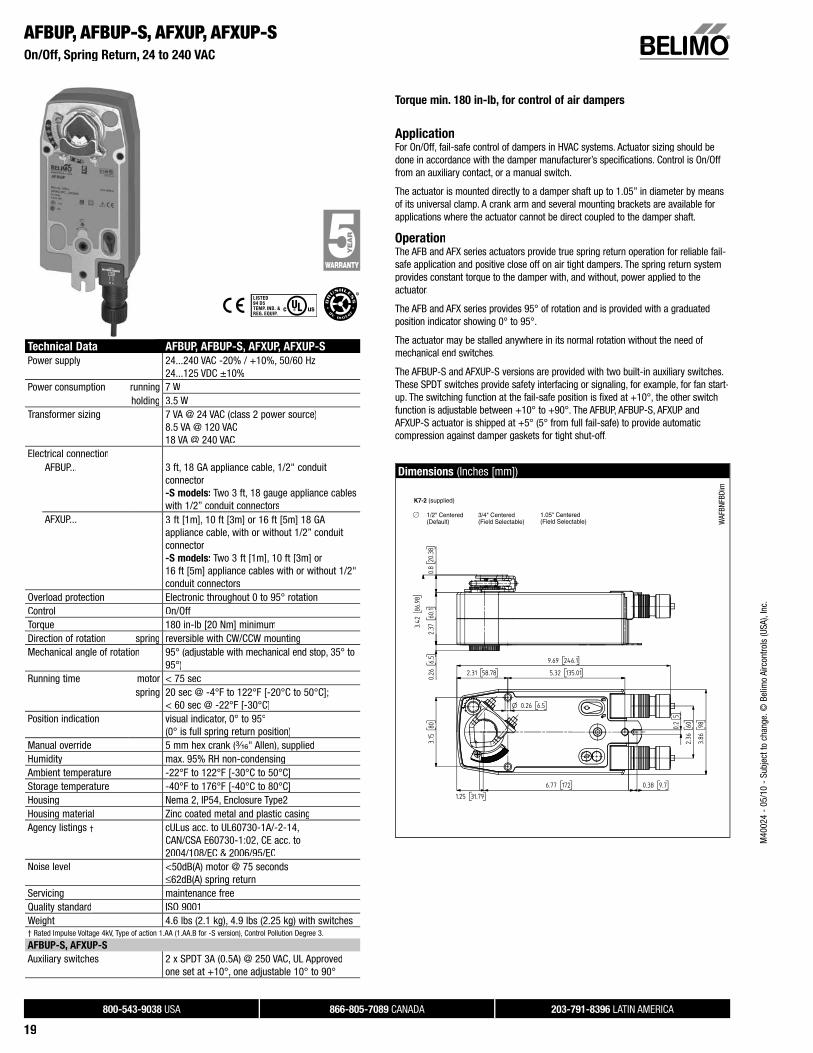
AFBUP, AFBUP-S, AFXUP, AFXUP-SOn/Off, Spring Return, 24 to 240 VAC
Torque min. 180 in-lb, for control of air dampers
ApplicationFor On/Off, fail-safe control of dampers in HVAC systems. Actuator sizing should bedone in accordance with the damper manufacturer’s specifications. Control is On/Offfrom an auxiliary contact, or a manual switch.
The actuator is mounted directly to a damper shaft up to 1.05” in diameter by meansof its universal clamp. A crank arm and several mounting brackets are available forapplications where the actuator cannot be direct coupled to the damper shaft.
OperationThe AFB and AFX series actuators provide true spring return operation for reliable fail-safe application and positive close off on air tight dampers. The spring return systemprovides constant torque to the damper with, and without, power applied to the actuator.
The AFB and AFX series provides 95° of rotation and is provided with a graduatedposition indicator showing 0° to 95°.
The actuator may be stalled anywhere in its normal rotation without the need of mechanical end switches.
The AFBUP-S and AFXUP-S versions are provided with two built-in auxiliary switches.These SPDT switches provide safety interfacing or signaling, for example, for fan start-up. The switching function at the fail-safe position is fixed at +10°, the other switchfunction is adjustable between +10° to +90°. The AFBUP, AFBUP-S, AFXUP andAFXUP-S actuator is shipped at +5° (5° from full fail-safe) to provide automaticcompression against damper gaskets for tight shut-off.
Dimensions (Inches [mm])
K7-2 (supplied)
1/2" Centered (Default)
3/4" Centered (Field Selectable)
1.05" Centered (Field Selectable) W
AFBN
FBDi
m
Technical Data AFBUP, AFBUP-S, AFXUP, AFXUP-S
Power supply 24...240 VAC -20% / +10%, 50/60 Hz24...125 VDC ±10%
Power consumption running 7 Wholding 3.5 W
Transformer sizing 7 VA @ 24 VAC (class 2 power source)8.5 VA @ 120 VAC18 VA @ 240 VAC
Electrical connectionAFBUP... 3 ft, 18 GA appliance cable, 1/2" conduit
connector-S models: Two 3 ft, 18 gauge appliance cables with 1/2” conduit connectors
AFXUP... 3 ft [1m], 10 ft [3m] or 16 ft [5m] 18 GA appliance cable, with or without 1/2” conduit connector-S models: Two 3 ft [1m], 10 ft [3m] or 16 ft [5m] appliance cables with or without 1/2" conduit connectors
Overload protection Electronic throughout 0 to 95° rotationControl On/OffTorque 180 in-lb [20 Nm] minimumDirection of rotation spring reversible with CW/CCW mountingMechanical angle of rotation 95° (adjustable with mechanical end stop, 35° to
95°)Running time motor < 75 sec
spring 20 sec @ -4°F to 122°F [-20°C to 50°C];< 60 sec @ -22°F [-30°C]
Position indication visual indicator, 0° to 95°(0° is full spring return position)
Manual override 5 mm hex crank (³⁄₁₆" Allen), suppliedHumidity max. 95% RH non-condensingAmbient temperature -22°F to 122°F [-30°C to 50°C]Storage temperature -40°F to 176°F [-40°C to 80°C]Housing Nema 2, IP54, Enclosure Type2Housing material Zinc coated metal and plastic casingAgency listings † cULus acc. to UL60730-1A/-2-14,
CAN/CSA E60730-1:02, CE acc. to2004/108/EC & 2006/95/EC
Noise level <50dB(A) motor @ 75 seconds≤62dB(A) spring return
Servicing maintenance freeQuality standard ISO 9001Weight 4.6 lbs (2.1 kg), 4.9 lbs (2.25 kg) with switches† Rated Impulse Voltage 4kV, Type of action 1.AA (1.AA.B for -S version), Control Pollution Degree 3.
AFBUP-S, AFXUP-S
Auxiliary switches 2 x SPDT 3A (0.5A) @ 250 VAC, UL Approvedone set at +10°, one adjustable 10° to 90°
M40
024
- 05
/10
- Su
bjec
t to
chan
ge. ©
Bel
imo
Airc
ontro
ls (U
SA),
Inc.
800-543-9038 USA 866-805-7089 CANADA 203-791-8396 LATIN AMERICA
20
AFBUP, AFBUP-S, AFXUP, AFXUP-SOn/Off, Spring Return, 24 to 240 VAC
Accessories
AV 8-25 Shaft extensionIND-AFB Damper position indicatorK7-2 Universal clamp for up to 1.05” dia jackshaftsKH-AFB Crank armTF-CC US Conduit fittingTool-06 8mm and 10 mm wrenchZG-100 Universal mounting bracketZG-101 Universal mounting bracketZG-118 Mounting bracket for Barber Colman® MA 3../4.., Honeywell®
Mod III or IV or Johnson® Series 100 replacement or new crank arm type installations
ZG-AFB Crank arm adaptor kit ZG-AFB118 Crank arm adaptor kitZS-100 Weather shield (metal)ZS-150 Weather shield (polycarbonate)ZS-260 Explosion-proof housingZS-300 NEMA 4X housingNote: When using AFBUP, AFBUP-S, AFXUP, AFXUP-S actuators, only use accessories listed on
this page.For actuator wiring information and diagrams, refer to Belimo Wiring Guide.
Typical Specification
On/Off spring return damper actuators shall be direct coupled type which requireno crank arm and linkage and be capable of direct mounting to a jackshaft up to a1.05” diameter. The actuators must be designed so that they may be used for eitherclockwise or counterclockwise fail-safe operation. Actuators shall be protectedfrom overload at all angles of rotation. If required, two SPDT auxiliary switch shall be provided having the capability of one being adjustable. Actuators with auxiliary switches must be constructed to meet the requirements for Double Insulation soan electrical ground is not required to meet agency listings. Actuators shall be cULus approved and have a 5 year warranty, and be manufactured under ISO 9001 International Quality Control Standards. Actuators shall be as manufactured by Belimo.
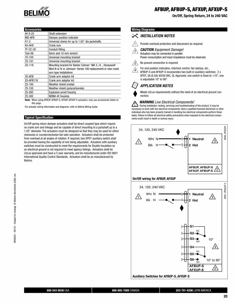
Wiring Diagrams
1 Provide overload protection and disconnect as required.
2 CAUTION Equipment Damage!Actuators may be connected in parallel.Power consumption and input impedance must be observed.
3 No ground connection is required.
4For end position indication, interlock control, fan startup, etc.,AFBUP-S and AFXUP-S incorporates two built-in auxiliary switches: 2 xSPDT, 3A (0.5A) @250 VAC, UL Approved, one switch is fi xed at +10°, oneis adjustable 10° to 90°.
Meets cULus requirements without the need of an electrical ground con-nection.
WARNING Live Electrical Components!G During installation, testing, servicing and troubleshooting of this product, it may be
necessary to work with live electrical components. Have a qualifi ed licensed electrician or otherindividual who has been properly trained in handling live electrical components perform these tasks. Failure to follow all electrical safety precautions when exposed to live electrical compo-nents could result in death or serious injury.
AFBUP, AFBUP-SAFXUP, AFBUP-S
W06
6_AF
B(X)
UP
On/Off wiring for AFBUP, AFXUP
Wht
Blk
AFBUP-SAFXUP-S
W06
7_AF
B(X)
UP-S
Auxiliary Switches for AFBUP-S, AFXUP-S
M40
024
- 05
/10
- Su
bjec
t to
chan
ge. ©
Bel
imo
Airc
ontro
ls (U
SA),
Inc.
800-543-9038 USA 866-805-7089 CANADA 203-791-8396 LATIN AMERICA
21
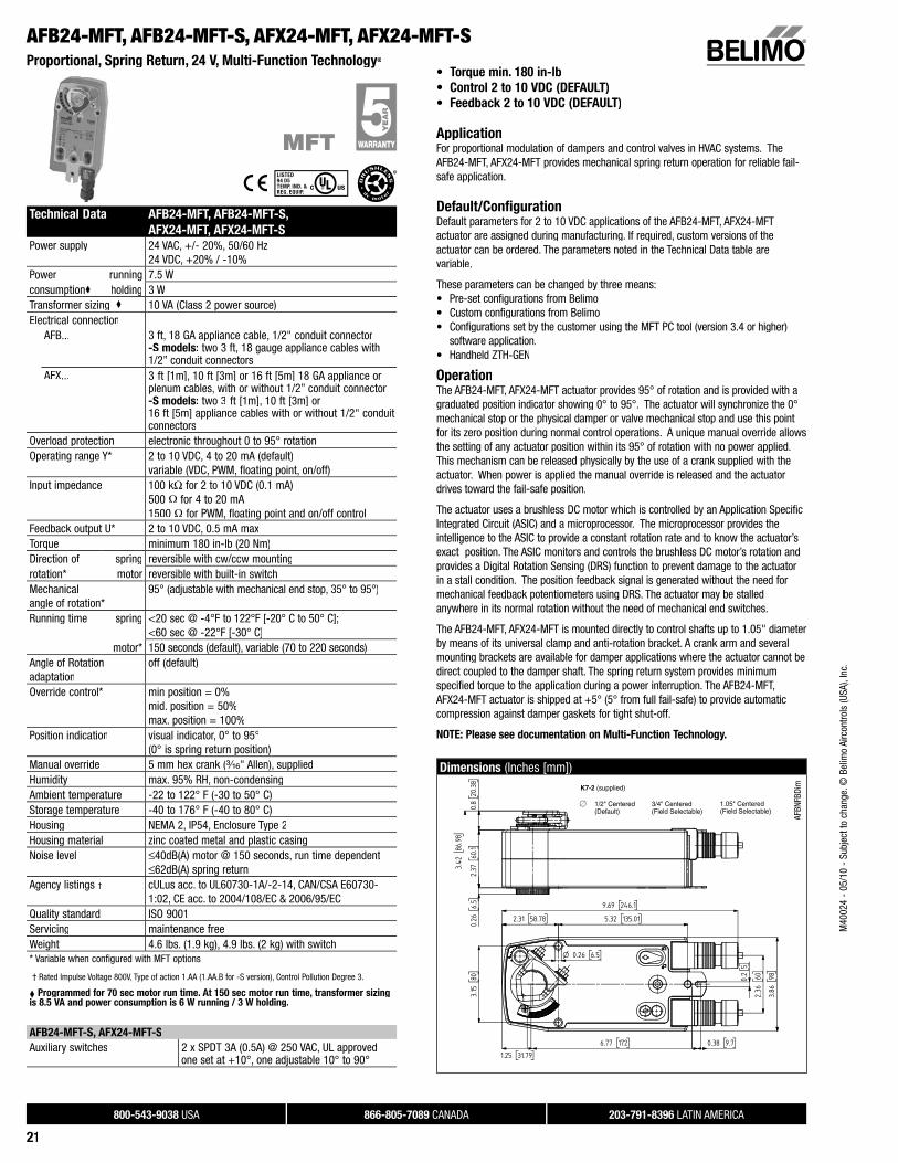
AFB24-MFT, AFB24-MFT-S, AFX24-MFT, AFX24-MFT-SProportional, Spring Return, 24 V, Multi-Function Technology®
• Torque min. 180 in-lb
• Control 2 to 10 VDC (DEFAULT)
• Feedback 2 to 10 VDC (DEFAULT)
ApplicationFor proportional modulation of dampers and control valves in HVAC systems. The AFB24-MFT, AFX24-MFT provides mechanical spring return operation for reliable fail-safe application.
Default/ConfigurationDefault parameters for 2 to 10 VDC applications of the AFB24-MFT, AFX24-MFTactuator are assigned during manufacturing. If required, custom versions of the actuator can be ordered. The parameters noted in the Technical Data table arevariable.
These parameters can be changed by three means:• Pre-set configurations from Belimo• Custom configurations from Belimo• Configurations set by the customer using the MFT PC tool (version 3.4 or higher)
software application.• Handheld ZTH-GEN
OperationThe AFB24-MFT, AFX24-MFT actuator provides 95° of rotation and is provided with a graduated position indicator showing 0° to 95°. The actuator will synchronize the 0°mechanical stop or the physical damper or valve mechanical stop and use this point for its zero position during normal control operations. A unique manual override allowsthe setting of any actuator position within its 95° of rotation with no power applied. This mechanism can be released physically by the use of a crank supplied with the actuator. When power is applied the manual override is released and the actuatordrives toward the fail-safe position.
The actuator uses a brushless DC motor which is controlled by an Application Specific Integrated Circuit (ASIC) and a microprocessor. The microprocessor provides theintelligence to the ASIC to provide a constant rotation rate and to know the actuator’s exact position. The ASIC monitors and controls the brushless DC motor’s rotation and provides a Digital Rotation Sensing (DRS) function to prevent damage to the actuatorin a stall condition. The position feedback signal is generated without the need formechanical feedback potentiometers using DRS. The actuator may be stalledanywhere in its normal rotation without the need of mechanical end switches.
The AFB24-MFT, AFX24-MFT is mounted directly to control shafts up to 1.05" diameterby means of its universal clamp and anti-rotation bracket. A crank arm and severalmounting brackets are available for damper applications where the actuator cannot bedirect coupled to the damper shaft. The spring return system provides minimumspecified torque to the application during a power interruption. The AFB24-MFT,AFX24-MFT actuator is shipped at +5° (5° from full fail-safe) to provide automaticcompression against damper gaskets for tight shut-off.
NOTE: Please see documentation on Multi-Function Technology.
Dimensions (Inches [mm])
AFBN
FBDi
m
Technical Data AFB24-MFT, AFB24-MFT-S,
AFX24-MFT, AFX24-MFT-S
Power supply 24 VAC, +/- 20%, 50/60 Hz24 VDC, +20% / -10%
Power running 7.5 Wconsumption holding 3 WTransformer sizing 10 VA (Class 2 power source)Electrical connection
AFB... 3 ft, 18 GA appliance cable, 1/2" conduit connector-S models: two 3 ft, 18 gauge appliance cables with1/2” conduit connectors
AFX... 3 ft [1m], 10 ft [3m] or 16 ft [5m] 18 GA appliance or plenum cables, with or without 1/2” conduit connector-S models: two 3 ft [1m], 10 ft [3m] or16 ft [5m] appliance cables with or without 1/2" conduit connectors
Overload protection electronic throughout 0 to 95° rotationOperating range Y* 2 to 10 VDC, 4 to 20 mA (default)
variable (VDC, PWM, floating point, on/off)Input impedance 100 kΩ for 2 to 10 VDC (0.1 mA)
500 Ω for 4 to 20 mA 1500 Ω for PWM, floating point and on/off control
Feedback output U* 2 to 10 VDC, 0.5 mA maxTorque minimum 180 in-lb (20 Nm)Direction of spring reversible with cw/ccw mountingrotation* motor reversible with built-in switchMechanicalangle of rotation*
95° (adjustable with mechanical end stop, 35° to 95°)
Running time spring <20 sec @ -4°F to 122°F [-20° C to 50° C];<60 sec @ -22°F [-30° C]
motor* 150 seconds (default), variable (70 to 220 seconds)Angle of Rotationadaptation
off (default)
Override control* min position = 0%mid. position = 50%max. position = 100%
Position indication visual indicator, 0° to 95°(0° is spring return position)
Manual override 5 mm hex crank (³⁄₁₆" Allen), suppliedHumidity max. 95% RH, non-condensingAmbient temperature -22 to 122° F (-30 to 50° C)Storage temperature -40 to 176° F (-40 to 80° C)Housing NEMA 2, IP54, Enclosure Type 2Housing material zinc coated metal and plastic casingNoise level ≤40dB(A) motor @ 150 seconds, run time dependent
≤62dB(A) spring returnAgency listings † cULus acc. to UL60730-1A/-2-14, CAN/CSA E60730-
1:02, CE acc. to 2004/108/EC & 2006/95/ECQuality standard ISO 9001Servicing maintenance freeWeight 4.6 lbs. (1.9 kg), 4.9 lbs. (2 kg) with switch* Variable when configured with MFT options
† Rated Impulse Voltage 800V, Type of action 1.AA (1.AA.B for -S version), Control Pollution Degree 3.
Programmed for 70 sec motor run time. At 150 sec motor run time, transformer sizingis 8.5 VA and power consumption is 6 W running / 3 W holding.i
K7-2 (supplied)
1/2" Centered (Default)
3/4" Centered (Field Selectable)
1.05" Centered (Field Selectable)
AFB24-MFT-S, AFX24-MFT-S
Auxiliary switches 2 x SPDT 3A (0.5A) @ 250 VAC, UL approvedone set at +10°, one adjustable 10° to 90°
M40
024
- 05
/10
- Su
bjec
t to
chan
ge. ©
Bel
imo
Airc
ontro
ls (U
SA),
Inc.
800-543-9038 USA 866-805-7089 CANADA 203-791-8396 LATIN AMERICA
22
AFB24-MFT, AFB24-MFT-S, AFX24-MFT, AFX24-MFT-SProportional, Spring Return, 24 V, Multi-Function Technology®
AFB24-MFT-SAFX24-MFT-S
Auxiliary Switches for AFB24-MFT-S, AFX24-MFT-S
W60
0_AF
B_AF
XW
399_
08
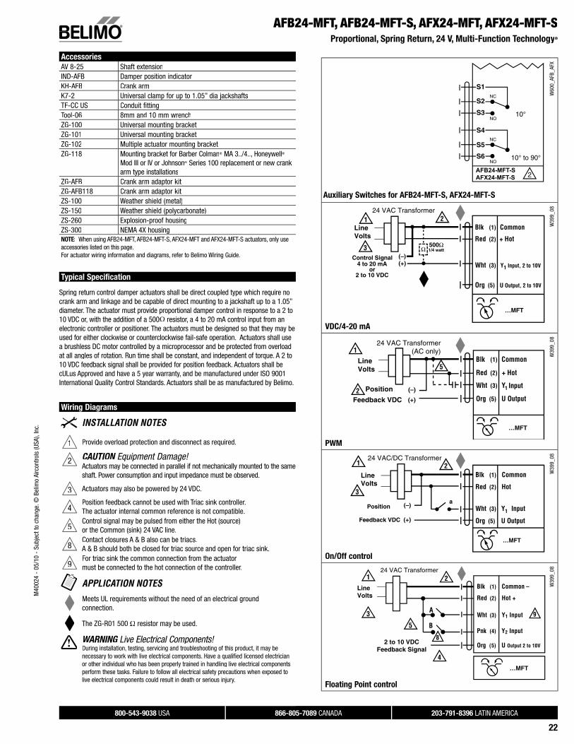
VDC/4-20 mA
W39
9_08
PWMM
W39
9_08
On/Off controlOff lW
399_
08
Floating Point control
Accessories
AV 8-25 Shaft extensionIND-AFB Damper position indicatorKH-AFB Crank armK7-2 Universal clamp for up to 1.05” dia jackshaftsTF-CC US Conduit fittingTool-06 8mm and 10 mm wrenchZG-100 Universal mounting bracketZG-101 Universal mounting bracketZG-102 Multiple actuator mounting bracketZG-118 Mounting bracket for Barber Colman® MA 3../4.., Honeywell®
Mod III or IV or Johnson® Series 100 replacement or new crank arm type installations
ZG-AFB Crank arm adaptor kit ZG-AFB118 Crank arm adaptor kitZS-100 Weather shield (metal)ZS-150 Weather shield (polycarbonate)ZS-260 Explosion-proof housingZS-300 NEMA 4X housingNOTE: When using AFB24-MFT, AFB24-MFT-S, AFX24-MFT and AFX24-MFT-S actuators, only use accessories listed on this page.For actuator wiring information and diagrams, refer to Belimo Wiring Guide.
Typical Specification
Spring return control damper actuators shall be direct coupled type which require no crank arm and linkage and be capable of direct mounting to a jackshaft up to a 1.05”diameter. The actuator must provide proportional damper control in response to a 2 to 10 VDC or, with the addition of a 500Ω resistor, a 4 to 20 mA control input from an electronic controller or positioner. The actuators must be designed so that they may be used for either clockwise or counterclockwise fail-safe operation. Actuators shall usea brushless DC motor controlled by a microprocessor and be protected from overloadat all angles of rotation. Run time shall be constant, and independent of torque. A 2 to10 VDC feedback signal shall be provided for position feedback. Actuators shall be cULus Approved and have a 5 year warranty, and be manufactured under ISO 9001International Quality Control Standards. Actuators shall be as manufactured by Belimo.
Wiring Diagrams
1 Provide overload protection and disconnect as required.
2 CAUTION Equipment Damage!Actuators may be connected in parallel if not mechanically mounted to the same shaft. Power consumption and input impedance must be observed.
3 Actuators may also be powered by 24 VDC.
4Position feedback cannot be used with Triac sink controller.The actuator internal common reference is not compatible.
5Control signal may be pulsed from either the Hot (source)or the Common (sink) 24 VAC line.
8Contact closures A & B also can be triacs.A & B should both be closed for triac source and open for triac sink.
9For triac sink the common connection from the actuatormust be connected to the hot connection of the controller.
Meets UL requirements without the need of an electrical groundconnection.
The ZG-R01 500 Ω resistor may be used.
WARNING Live Electrical Components!During installation, testing, servicing and troubleshooting of this product, it may be necessary to work with live electrical components. Have a qualifi ed licensed electrician or other individual who has been properly trained in handling live electrical components perform these tasks. Failure to follow all electrical safety precautions when exposed to live electrical components could result in death or serious injury.
M40
024
- 05
/10
- Su
bjec
t to
chan
ge. ©
Bel
imo
Airc
ontro
ls (U
SA),
Inc.
800-543-9038 USA 866-805-7089 CANADA 203-791-8396 LATIN AMERICA
23
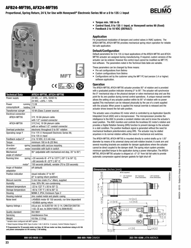
AFB24-MFT95, AFX24-MFT95Proportional, Spring Return, 24 V, for Use with Honeywell® Electronic Series 90 or a 0 to 135 Ω Input
• Torque min. 180 in-lb
• Control fixed, 0 to 135 Ω input, or Honeywell series 90 (fixed)
• Feedback 2 to 10 VDC (DEFAULT)
ApplicationFor proportional modulation of dampers and control valves in HVAC systems. The AFB24-MFT95, AFX24-MFT95 provides mechanical spring return operation for reliable fail-safe application.
Default/ConfigurationDefault parameters for 0 to 135 Ω Input applications of the AFB24-MFT95 and AFX24-MFT95 actuator are assigned during manufacturing. If required, custom versions of the actuator can be ordered. However the control input cannot be modified via MFT PCtool software. The parameters noted in the Technical Data table are variable.
These parameters can be changed by three means:• Pre-set configurations from Belimo• Custom configurations from Belimo• Configurations set by the customer using the MFT PC tool (version 3.4 or higher)
software application.
OperationThe AFB24-MFT95, AFX24-MFT95 actuator provides 95° of rotation and is provided with a graduated position indicator showing 0° to 95°. The actuator will synchronize the 0° mechanical stop or the physical damper or valve mechanical stop and use thispoint for its zero position during normal control operations. A unique manual overrideallows the setting of any actuator position within its 95° of rotation with no power applied.This mechanism can be released physically by the use of a crank supplied with the actuator. When power is applied the manual override is released and the actuator drives toward the fail-safe position.
The actuator uses a brushless DC motor which is controlled by an Application Specific Integrated Circuit (ASIC) and a microprocessor. The microprocessor provides theintelligence to the ASIC to provide a constant rotation rate and to know the actuator’s exact position. The ASIC monitors and controls the brushless DC motor’s rotation and provides a Digital Rotation Sensing (DRS) function to prevent damage to the actuatorin a stall condition. The position feedback signal is generated without the need for mechanical feedback potentiometers using DRS. The actuator may be stalled anywhere in its normal rotation without the need of mechanical end switches.
The AFB24-MFT95, AFX24-MFT95 is mounted directly to control shafts up to 1.05"diameter by means of its universal clamp and anti-rotation bracket. A crank arm and several mounting brackets are available for damper applications where the actuatorcannot be direct coupled to the damper shaft. The spring return system providesminimum specified torque to the application during a power interruption. The AFB24-MFT95, AFX24-MFT95 actuator is shipped at +5° (5° from full fail-safe) to provide automatic compression against damper gaskets for tight shut-off.
Technical Data AFB24-MFT95, AFX24-MFT95
Power supply 24 VAC, +/- 20%, 50/60 Hz24 VDC, +20% / -10%
Powerconsumption
running 7.5 Wholding 3 W
Transformer sizing 10 VA (Class 2 power source)Electrical connection
AFB24-MFT95 3 ft, 18 GA plenum cable,with 1/2” conduit connector
AFX24-MFT95 3 ft [1m], 18 GA plenum cable,with or without 1/2” conduit connector
Overload protection electronic throughout 0 to 95° rotationOperating range Y 0 to 135 Ω Honeywell Electronic Series 90,
0 to 135 Ω inputFeedback output U* 2 to 10 VDC, 0.5 mA maxTorque minimum 180 in-lb (20 Nm)Directionof rotation*
spring reversible with cw/ccw mountingmotor reversible with built-in switch
Mechanicalangle of rotation*
95° (adjustable with mechanical end stop, 35° to 95°)
Running time spring <20 seconds @ -4°F to 122°F [-20° C to 50° C];<60 seconds @ -22°F [-30° C]
motor* 150 seconds (default), variable (70 to 220 seconds)Angle of Rotation adaptation
off (default)
Position indication visual indicator, 0° to 95°(0° is spring return position)
Manual override 5 mm hex crank (³⁄₁₆" Allen), suppliedHumidity max. 95% RH, non-condensingAmbient temperature -22 to 122° F (-30 to 50° C)Storage temperature -40 to 176° F (-40 to 80° C)Housing NEMA 2, IP54, Enclosure Type 2Housing material zinc coated metal and plastic casingNoise level ≤40dB(A) motor @ 150 seconds, run time dependent
≤62dB(A) spring returnAgency listings † cULus acc. to UL60730-1A/-2-14, CAN/CSA E60730-
1:02, CE acc. to 2004/108/EC & 2006/95/ECQuality standard ISO 9001Servicing maintenance freeWeight 4.6 lbs. (1.9 kg)* Variable when configured with MFT options
† Rated Impulse Voltage 800V, Type of action 1.AA (1.AA.B for -S version), Control Pollution Degree 3.
Programmed for 70 seconds motor run time. At 150 sec motor run time, transformer sizing is 8.5 VA
and power consumption is 6 W running / 3 W holding.
Dimensions (Inches [mm])
AFBN
FBDi
mK7-2 (supplied)
1/2" Centered (Default)
3/4" Centered (Field Selectable)
1.05" Centered (Field Selectable)
M40
024
- 05
/10
- Su
bjec
t to
chan
ge. ©
Bel
imo
Airc
ontro
ls (U
SA),
Inc.
800-543-9038 USA 866-805-7089 CANADA 203-791-8396 LATIN AMERICA
24
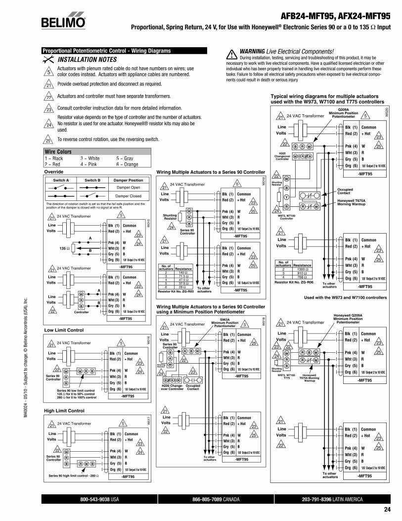
AFB24-MFT95, AFX24-MFT95Proportional, Spring Return, 24 V, for Use with Honeywell® Electronic Series 90 or a 0 to 135 Ω Input
Proportional Potentiometric Control - Wiring Diagrams
5Actuators with plenum rated cable do not have numbers on wires; use color codes instead. Actuators with appliance cables are numbered.
21 Provide overload protection and disconnect as required.
22 Actuators and controller must have separate transformers.
23 Consult controller instruction data for more detailed information.
24
Resistor value depends on the type of controller and the number of actuators.No resistor is used for one actuator. Honeywell® resistor kits may also be used.
25 To reverse control rotation, use the reversing switch.
WARNING Live Electrical Components!G During installation, testing, servicing and troubleshooting of this product, it may be
necessary to work with live electrical components. Have a qualifi ed licensed electrician or otherindividual who has been properly trained in handling live electrical components perform these tasks. Failure to follow all electrical safety precautions when exposed to live electrical compo-nents could result in death or serious injury.
22
22
23
25
23
25
23
25
23
25
24
21
21
Line
Volts
Line
Volts
24 VAC Transformer
-MFT95
Blk (1) CommonRed (2) + Hot
Pnk (4) W
Wht (3) R
Gry (5) B
Org (6) ‘U5’ Output 2 to 10 VDC
-MFT95
Blk (1) CommonRed (2) + Hot
Pnk (4) W
Wht (3) R
Gry (5) B
Org (6) ‘U5’ Output 2 to 10 VDC
-MFT95
Blk (1) CommonRed (2) + Hot
Pnk (4) W
Wht (3) R
Gry (5) B
Org (6) ‘U5’ Output 2 to 10 VDC
-MFT95
Blk (1) CommonRed (2) + Hot
Pnk (4) W
Wht (3) R
Gry (5) B
Org (6) ‘U5’ Output 2 to 10 VDC
Resistor Kit No. ZG-R06
No. of actuators Resistance 2 1300 Ω 3 910 Ω 4 768 Ω
22
22
23
24
Typical wiring diagrams for multiple actuatorsused with the W973, W7100 and T775 controllers
W02
0
To otheractuators
Q209AMinimum Position
Potentiometer
H205ChangeoverController
W973, W7100Controller
OccupiedContact
Honeywell T675AMorning Warmup
ShuntingResistor
To otheractuators
Honeywell Q209AMinimum Position
Potentiometer
ShuntingResistor
Used with the W973 and W7100 controllers
Honeywell T675A Morning
Warmup
W973, W7100 T775
W
W
W
R
R R
Y
B
B
W R B
21
21
Line
Volts
Line
Volts
24 VAC Transformer
W W
R
R
WR
B
B
5
23
25
23
25
24
Line
Volts
Line
Volts
21
21
24 VAC Transformer
-MFT95
Blk (1) CommonRed (2) + Hot
Pnk (4) WWht (3) RGry (5) BOrg (6) ‘U5’ Output 2 to 10 VDC
-MFT95
Blk (1) CommonRed (2) + Hot
Pnk (4) WWht (3) RGry (5) BOrg (6) ‘U5’ Output 2 to 10 VDC
W01
8
Wiring Multiple Actuators to a Series 90 Controller
To otheractuatorsResistor Kit No. ZG-R03
Series 90Controller
ShuntingResistor
W
R
B
No. of actuators Resistance 2 140 Ω 3 71.5 Ω 4 47.5 Ω 5 37.5 Ω 6 28 Ω
Wiring Multiple Actuators to a Series 90 Controllerusing a Minimum Position Potentiometer
22
22
2324
Line
Volts
Line
Volts
21
21
24 VAC Transformer
25
23
25
-MFT95
Blk (1) CommonRed (2) + Hot
Pnk (4) WWht (3) RGry (5) BOrg (6) ‘U5’ Output 2 to 10 VDC
-MFT95
Blk (1) CommonRed (2) + Hot
Pnk (4) WWht (3) RGry (5) BOrg (6) ‘U5’ Output 2 to 10 VDC
W01
9
To otheractuators
Series 90Controller
S963AMinimum Position
Potentiometer
H205 Change-over Controller
OccupiedContact
ShuntingResistor
W
W
W
R
R
RB
B
B
5
5
Override
Switch A Switch B Damper Position
Damper Open
Damper Closed
The direction of rotation switch is set so that the fail safe position and the position of the damper is closed with no signal at wire R.
W01
5W
016
Low Limit Control
21
22
22
23
24
21
21
23
24
23
24
Blk (1) CommonRed (2) + Hot
Pnk (4) WWht (3) RGry (5) BOrg (6) ‘U5’ Output 2 to 10 VDC
A
B
A
B
Line
Volts
Line
Volts
Line
Volts
Line
Volts
24 VAC Transformer
24 VAC Transformer
24 VAC Transformer
135 Ω
Controller
-MFT95
-MFT95
W
R
B
Blk (1) CommonRed (2) + Hot
Pnk (4) WWht (3) RGry (5) BOrg (6) ‘U5’ Output 2 to 10 VDC
-MFT95
Blk (1) CommonRed (2) + Hot
Pnk (4) W
Wht (3) R
Gry (5) B
Org (6) ‘U5’ Output 2 to 10 VDCSeries 90 low limit control135 Ω for 0 to 50% control280 Ω for 0 to 100% control
Series 90Controller
W W
R
R
B
B
Wire Colors1 = Black2 = Red
3 = White4 = Pink
5 = Gray6 = Orange
5
5
W01
7
High Limit Control
22
21
23
24
Line
Volts
24 VAC Transformer
-MFT95
Blk (1) CommonRed (2) + Hot
Pnk (4) W
Wht (3) R
Gry (5) B
Org (6) ‘U5’ Output 2 to 10 VDC
Series 90 high limit control - 280 Ω
Series 90Controller
W
W
R
RB B
5
M40
024
- 05
/10
- Su
bjec
t to
chan
ge. ©
Bel
imo
Airc
ontro
ls (U
SA),
Inc.
800-543-9038 USA 866-805-7089 CANADA 203-791-8396 LATIN AMERICA
43
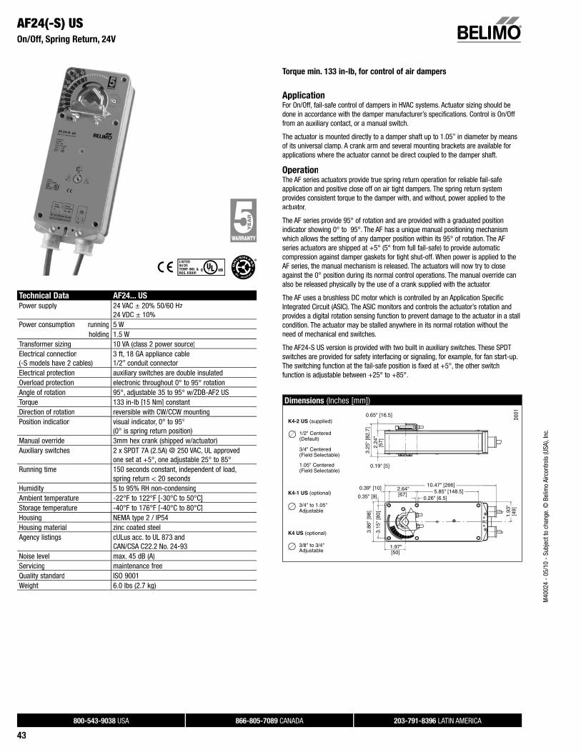
AF24(-S) USOn/Off, Spring Return, 24V
Torque min. 133 in-lb, for control of air dampers
ApplicationFor On/Off, fail-safe control of dampers in HVAC systems. Actuator sizing should bedone in accordance with the damper manufacturer’s specifications. Control is On/Offfrom an auxiliary contact, or a manual switch.
The actuator is mounted directly to a damper shaft up to 1.05” in diameter by meansof its universal clamp. A crank arm and several mounting brackets are available forapplications where the actuator cannot be direct coupled to the damper shaft.
OperationThe AF series actuators provide true spring return operation for reliable fail-safe application and positive close off on air tight dampers. The spring return system provides consistent torque to the damper with, and without, power applied to theactuator.
The AF series provide 95° of rotation and are provided with a graduated positionindicator showing 0° to 95°. The AF has a unique manual positioning mechanismwhich allows the setting of any damper position within its 95° of rotation. The AF series actuators are shipped at +5° (5° from full fail-safe) to provide automatic compression against damper gaskets for tight shut-off. When power is applied to theAF series, the manual mechanism is released. The actuators will now try to closeagainst the 0° position during its normal control operations. The manual override canalso be released physically by the use of a crank supplied with the actuator.
The AF uses a brushless DC motor which is controlled by an Application Specific Integrated Circuit (ASIC). The ASIC monitors and controls the actuator’s rotation and provides a digital rotation sensing function to prevent damage to the actuator in a stallcondition. The actuator may be stalled anywhere in its normal rotation without theneed of mechanical end switches.
The AF24-S US version is provided with two built in auxiliary switches. These SPDTswitches are provided for safety interfacing or signaling, for example, for fan start-up. The switching function at the fail-safe position is fixed at +5°, the other switch function is adjustable between +25° to +85°.
Dimensions (Inches [mm])
1.97"
3.15
" [8
0]
3.86
" [9
8]3.
25"
[82.
7]
2.24
" [5
7]
[50]
1.93
"[4
9]
2.64"[67]
0.26" [6.5]5.85" [148.5]
10.47" [266]
0.35" [9]
0.39" [10]
0.65" [16.5]
0.19" [5]
K4-2 US (supplied)
1/2" Centered (Default)
3/4" Centered (Field Selectable)
1.05" Centered (Field Selectable)
K4-1 US (optional)
3/4" to 1.05" Adjustable
K4 US (optional)
3/8" to 3/4" Adjustable
D001
Technical Data AF24... US
Power supply 24 VAC ± 20% 50/60 Hz24 VDC ± 10%
Power consumption running 5 Wholding 1.5 W
Transformer sizing 10 VA (class 2 power source)Electrical connection(-S models have 2 cables)
3 ft, 18 GA appliance cable1/2” conduit connector
Electrical protection auxiliary switches are double insulatedOverload protection electronic throughout 0° to 95° rotationAngle of rotation 95°, adjustable 35 to 95° w/ZDB-AF2 USTorque 133 in-lb [15 Nm] constantDirection of rotation reversible with CW/CCW mountingPosition indication visual indicator, 0° to 95°
(0° is spring return position)Manual override 3mm hex crank (shipped w/actuator)Auxiliary switches 2 x SPDT 7A (2.5A) @ 250 VAC, UL approved
one set at +5°, one adjustable 25° to 85°Running time 150 seconds constant, independent of load,
spring return < 20 secondsHumidity 5 to 95% RH non-condensingAmbient temperature -22°F to 122°F [-30°C to 50°C]Storage temperature -40°F to 176°F [-40°C to 80°C]Housing NEMA type 2 / IP54Housing material zinc coated steelAgency listings cULus acc. to UL 873 and
CAN/CSA C22.2 No. 24-93Noise level max. 45 dB (A)Servicing maintenance freeQuality standard ISO 9001Weight 6.0 lbs (2.7 kg)
M40
024
- 05
/10
- Su
bjec
t to
chan
ge. ©
Bel
imo
Airc
ontro
ls (U
SA),
Inc.
800-543-9038 USA 866-805-7089 CANADA 203-791-8396 LATIN AMERICA
44
Accessories
AV 10-18 Shaft extensionIND-AF2 Damper position indicatorK4 US Universal clamp for 3/8” to 3/4” shaftsK4-1 US Universal clamp for up to 1.05” dia jackshaftsK4-H Universal clamp for hexshafts 3/8” to 5/8”KH-AF Crank arm for up to 3/4” round shaft (Series 2)KH-AF-1 Crank arm for up to 1.05” jackshaft (Series 2)KH-AFV V-bolt kit for KH-AF and KH-AF-1Tool-06 8mm and 10 mm wrenchZG-HTR Thermostat/Heater KitZDB-AF2 US Angle of rotation limiterZG-100 Universal mounting bracketZG-101 Universal mounting bracketZG-102 Multiple actuator mounting bracketZG-106 Mounting bracket for Honeywell® Mod IVZG-107 Mounting bracket for Honeywell® Mod III or Johnson® Series
100 replacement or new crank arm type installationsZG-108 Mounting bracket for Barber Colman® MA 3../4..,
Honeywell® Mod III or IV or Johnson® Series 100replacement or new crank arm type installations
ZG-AF US Crank arm adaptor kit for AF/NF ZG-AF108 Crank arm adaptor kit for AF/NF ZS-100 Weather shield (metal)ZS-150 Weather shield (polycarbonate)ZS-260 Explosion-proof housingZS-300 NEMA 4X housingNOTE: When using AF24 US and AF24-S US actuators, only use accessories listed on this page.
For actuator wiring information and diagrams, refer to Belimo Wiring Guide.
Typical Specification
On/Off spring return damper actuators shall be direct coupled type which require nocrank arm and linkage and be capable of direct mounting to a jackshaft up to a 1.05”diameter. The actuators must be designed so that they may be used for eitherclockwise or counterclockwise fail-safe operation. Actuators shall have a manualpositioning mechanism accessible on its cover. Actuators shall use a brushless DC motor and be protected from overload at all angles of rotation. Run time shall beconstant and independent of torque. If required, two SPDT auxiliary switches shall be provided with one switch having the capability of being adjustable. Actuators with switches must be constructed to meet the requirement for Double Insulation so an electrical ground connection is not required to meet agency listings. Actuators shall becULus listed, have a 5 year warranty, and be manufactured under ISO 9001 International Quality Control Standards. Actuators shall be as manufactured by Belimo.
AF24(-S) USOn/Off, Spring Return, 24V
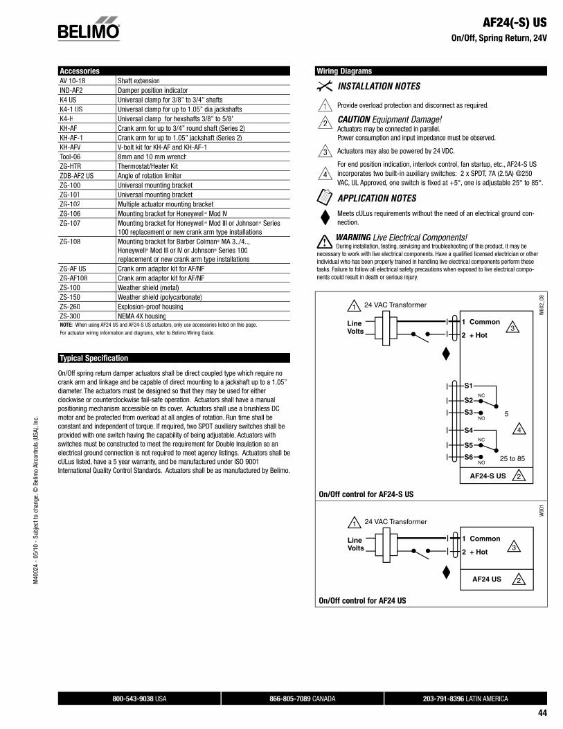
Wiring Diagrams
1 Provide overload protection and disconnect as required.
2 CAUTION Equipment Damage!Actuators may be connected in parallel.Power consumption and input impedance must be observed.
3 Actuators may also be powered by 24 VDC.
4For end position indication, interlock control, fan startup, etc., AF24-S US incorporates two built-in auxiliary switches: 2 x SPDT, 7A (2.5A) @250VAC, UL Approved, one switch is fixed at +5°, one is adjustable 25° to 85°.
Meets cULus requirements without the need of an electrical ground con-nection.
WARNING Live Electrical Components!G During installation, testing, servicing and troubleshooting of this product, it may be
necessary to work with live electrical components. Have a qualifi ed licensed electrician or otherindividual who has been properly trained in handling live electrical components perform these tasks. Failure to follow all electrical safety precautions when exposed to live electrical compo-nents could result in death or serious injury.
W00
2_08
On/Off control for AF24-S US
1 Common
2 + Hot
1
2
24 VAC Transformer
AF24 US
Line Volts 3
W00
1
On/Off control for AF24 US
M40
024
- 05
/10
- Su
bjec
t to
chan
ge. ©
Bel
imo
Airc
ontro
ls (U
SA),
Inc.
800-543-9038 USA 866-805-7089 CANADA 203-791-8396 LATIN AMERICA
45
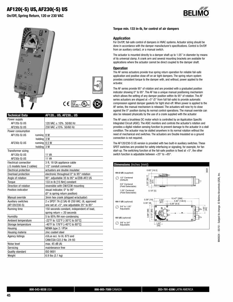
Torque min. 133 in-lb, for control of air dampers
ApplicationFor On/Off, fail-safe control of dampers in HVAC systems. Actuator sizing should bedone in accordance with the damper manufacturer’s specifications. Control is On/Offfrom an auxiliary contact, or a manual switch.
The actuator is mounted directly to a damper shaft up to 1.05” in diameter by meansof its universal clamp. A crank arm and several mounting brackets are available forapplications where the actuator cannot be direct coupled to the damper shaft.
OperationThe AF series actuators provide true spring return operation for reliable fail-safe application and positive close off on air tight dampers. The spring return system provides consistent torque to the damper with, and without, power applied to theactuator.
The AF series provide 95° of rotation and are provided with a graduated positionindicator showing 0° to 95°. The AF has a unique manual positioning mechanism which allows the setting of any damper position within its 95° of rotation. The AF series actuators are shipped at +5° (5° from full fail-safe) to provide automatic compression against damper gaskets for tight shut-off. When power is applied to theAF series, the manual mechanism is released. The actuators will now try to closeagainst the 0° position during its normal control operations. The manual override canalso be released physically by the use of a crank supplied with the actuator.
The AF uses a brushless DC motor which is controlled by an Application Specific Integrated Circuit (ASIC). The ASIC monitors and controls the actuator’s rotation and provides a digital rotation sensing function to prevent damage to the actuator in a stallcondition. The actuator may be stalled anywhere in its normal rotation without theneed of mechanical end switches. The actuators are Double Insulated so a ground connection is not required.
The AF120/230-S US version is provided with two built-in auxiliary switches. TheseSPDT switches are provided for safety interfacing or signaling, for example, for fanstart-up. The switching function at the fail-safe position is fixed at +5°, the otherswitch function is adjustable between +25° to +85°.
Dimensions (Inches [mm])
1.97"
3.15
" [8
0]
3.86
" [9
8]3.
25"
[82.
7]
2.24
" [5
7]
[50]
1.93
"[4
9]
2.64"[67]
0.26" [6.5]5.85" [148.5]
10.47" [266]
0.35" [9]
0.39" [10]
0.65" [16.5]
0.19" [5]
K4-2 US (supplied)
1/2" Centered (Default)
3/4" Centered (Field Selectable)
1.05" Centered (Field Selectable)
K4-1 US (optional)
3/4" to 1.05" Adjustable
K4 US (optional)
3/8" to 3/4" Adjustable
D001
AF120(-S) US, AF230(-S) US On/Off, Spring Return, 120 or 230 VAC
Technical Data AF120... US, AF230... US
Power supplyAF120(-S) US 120 VAC ± 10% 50/60 HzAF230(-S) US 230 VAC ±15% 50/60 Hz
Power consumptionAF120(-S) US running 8 W
holding 3 WAF230(-S) US running 8.5 W
holding 3 WTransformer sizing
AF120(-S) US 11 VAAF230(-S) US 11 VA
Electrical connection(-S models have 2 cables)
3 ft, 18 GA appliance cable1/2” conduit connector
Electrical protection actuators are double insulatedOverload protection electronic throughout 0° to 95° rotationAngle of rotation 95°, adjustable 35 to 95° w/ZDB-AF2 USTorque 133 in-lb [15 Nm] constantDirection of rotation reversible with CW/CCW mountingPosition indication visual indicator, 0° to 95°
(0° is spring return position)Manual override 3mm hex crank (shipped w/actuator)Auxiliary switches (AF120/230-S)
2 x SPDT 7A (2.5A) @ 250 VAC, UL approvedone set at +5°, one adjustable 25° to 85°
Running time 150 seconds constant, independent of load,spring return < 20 seconds
Humidity 5 to 95% RH non-condensingAmbient temperature -22°F to 122°F [-30°C to 50°C]Storage temperature -40°F to 176°F [-40°C to 80°C]Housing NEMA type 2 / IP54Housing material zinc coated steelAgency listings cULus acc. to UL 873 and
CAN/CSA C22.2 No. 24-93Noise level max. 45 dB (A)Servicing maintenance freeQuality standard ISO 9001Weight 6.9 lbs (3.1 kg)
M40
024
- 05
/10
- Su
bjec
t to
chan
ge. ©
Bel
imo
Airc
ontro
ls (U
SA),
Inc.
800-543-9038 USA 866-805-7089 CANADA 203-791-8396 LATIN AMERICA
46
AF120(-S) US, AF230(-S) USOn/Off, Spring Return, 120 or 230 VAC
Accessories
AV 10-18 Shaft extensionIND-AF2 Damper position indicatorK4 US Universal clamp for 3/8” to 3/4” shaftsK4-1 US Universal clamp for up to 1.05” dia jackshaftsKH-AF Crank arm for up to 3/4” round shaft (Series 2)KH-AF-1 Crank arm for up to 1.05” jackshaft (Series 2)KH-AFV V-bolt kit for KH-AF and KH-AF-1Tool-06 8mm and 10 mm wrenchZG-HTR Thermostat/Heater KitZDB-AF2 US Angle of rotation limiterZG-100 Universal mounting bracketZG-101 Universal mounting bracketZG-102 Multiple actuator mounting bracketZG-106 Mounting bracket for Honeywell® Mod IV replacement or new
crank arm type installationsZG-107 Mounting bracket for Honeywell® Mod III or Johnson® Series
100 replacement or new crank arm type installationsZG-108 Mounting bracket for Barber Colman® MA 3../4..,
Honeywell® Mod III or IV or Johnson® Series 100replacement or new crank arm type installations
ZG-AF US Crank arm adaptor kit for AF/NF ZG-AF108 Crank arm adaptor kit for AF/NF ZS-100 Weather shield (metal)ZS-150 Weather shield (polycarbonate)ZS-260 Explosion-proof housingZS-300 NEMA 4X housingNOTE: When using AF120/230 US and AF120/230-S US actuators, only use accessories listed on this page.
For actuator wiring information and diagrams, refer to Belimo Wiring Guide.
Typical Specification
On/Off spring return damper actuators shall be direct coupled type which require no crank arm and linkage and be capable of direct mounting to ajjackshaft up to a 1.05” diameter. The actuators must be designed so thatthey may be used for either clockwise or counterclockwise fail-safe operation. Actuators shall have a manual positioning mechanism accessible on its cover. Actuators shall use a brushless DC motor and be protected from overload at all angles of rotation. Run time shall be constant andindependent of torque. If required, two SPDT auxiliary switches shall be provided with one switch having the capability of being adjustable. Actuatorsmust be constructed to meet the requirement for Double Insulation so anelectrical ground connection is not required to meet agency listings. AActuators shall be cULus listed, have a 5 year warranty, and be manufactured under ISO 9001 International Quality Control Standards. AActuators shall be as manufactured by Belimo.
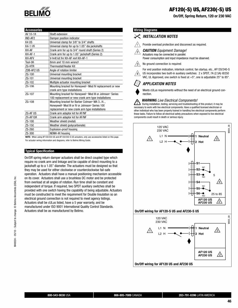
Wiring Diagrams
1 Provide overload protection and disconnect as required.
2 CAUTION Equipment Damage!Actuators may be connected in parallel.Power consumption and input impedance must be observed.
3 No ground connection is required.
4For end position indication, interlock control, fan startup, etc., AF120/240-SUS incorporates two built-in auxiliary switches: 2 x SPDT, 7A (2.5A) @250 VAC, UL Approved, one switch is fixed at +5°, one is adjustable 25° to 85°.
Meets cULus requirements without the need of an electrical ground con-nection.
WARNING Live Electrical Components!G During installation, testing, servicing and troubleshooting of this product, it may be
necessary to work with live electrical components. Have a qualifi ed licensed electrician orother individual who has been properly trained in handling live electrical components performthese tasks. Failure to follow all electrical safety precautions when exposed to live electricalcomponents could result in death or serious injury.
W00
4_08
On/Off wiring for AF120-S US and AF230-S US
W00
3_08
On/Off wiring for AF120 US and AF230 US
M40
024
- 05
/10
- Su
bjec
t to
chan
ge. ©
Bel
imo
Airc
ontro
ls (U
SA),
Inc.
800-543-9038 USA 866-805-7089 CANADA 203-791-8396 LATIN AMERICA
47
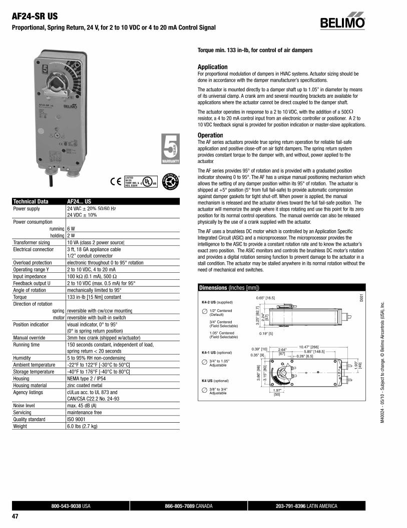
Technical Data AF24... US
Power supply 24 VAC ± 20% 50/60 Hz24 VDC ± 10%
Power consumptionrunning 6 Wholding 2 W
Transformer sizing 10 VA (class 2 power source)Electrical connection 3 ft, 18 GA appliance cable
1/2” conduit connectorOverload protection electronic throughout 0 to 95° rotationOperating range Y 2 to 10 VDC, 4 to 20 mA Input impedance 100 kΩ (0.1 mA), 500 ΩFeedback output U 2 to 10 VDC (max. 0.5 mA) for 95°Angle of rotation mechanically limited to 95°Torque 133 in-lb [15 Nm] constantDirection of rotation
spring reversible with cw/ccw mountingmotor reversible with built-in switch
Position indication visual indicator, 0° to 95°(0° is spring return position)
Manual override 3mm hex crank (shipped w/actuator)Running time 150 seconds constant, independent of load,
spring return < 20 secondsHumidity 5 to 95% RH non-condensingAmbient temperature -22°F to 122°F [-30°C to 50°C]Storage temperature -40°F to 176°F [-40°C to 80°C]Housing NEMA type 2 / IP54Housing material zinc coated metalAgency listings cULus acc. to UL 873 and
CAN/CSA C22.2 No. 24-93Noise level max. 45 dB (A)Servicing maintenance freeQuality standard ISO 9001Weight 6.0 lbs (2.7 kg)
Torque min. 133 in-lb, for control of air dampers
ApplicationFor proportional modulation of dampers in HVAC systems. Actuator sizing should bedone in accordance with the damper manufacturer’s specifications.
The actuator is mounted directly to a damper shaft up to 1.05” in diameter by meansof its universal clamp. A crank arm and several mounting brackets are available forapplications where the actuator cannot be direct coupled to the damper shaft.
The actuator operates in response to a 2 to 10 VDC, with the addition of a 500Ωresistor, a 4 to 20 mA control input from an electronic controller or positioner. A 2 to10 VDC feedback signal is provided for position indication or master-slave applications.
OperationThe AF series actuators provide true spring return operation for reliable fail-safe application and positive close-off on air tight dampers. The spring return system provides constant torque to the damper with, and without, power applied to the actuator.
The AF series provides 95° of rotation and is provided with a graduated positionindicator showing 0 to 95°. The AF has a unique manual positioning mechanism whichallows the setting of any damper position within its 95° of rotation. The actuator isshipped at +5° position (5° from full fail-safe) to provide automatic compressionagainst damper gaskets for tight shut-off. When power is applied, the manual mechanism is released and the actuator drives toward the full fail-safe position. The actuator will memorize the angle where it stops rotating and use this point for its zeroposition for its normal control operations. The manual override can also be released physically by the use of a crank supplied with the actuator.
The AF uses a brushless DC motor which is controlled by an Application Specific Integrated Circuit (ASIC) and a microprocessor. The microprocessor provides theintelligence to the ASIC to provide a constant rotation rate and to know the actuator’s exact zero position. The ASIC monitors and controls the brushless DC motor’s rotationand provides a digital rotation sensing function to prevent damage to the actuator in astall condition. The actuator may be stalled anywhere in its normal rotation without theneed of mechanical end switches.
Dimensions (Inches [mm])
1.97"
3.15
" [8
0]
3.86
" [9
8]3.
25"
[82.
7]
2.24
" [5
7]
[50]
1.93
"[4
9]
2.64"[67]
0.26" [6.5]5.85" [148.5]
10.47" [266]
0.35" [9]
0.39" [10]
0.65" [16.5]
0.19" [5]
K4-2 US (supplied)
1/2" Centered (Default)
3/4" Centered (Field Selectable)
1.05" Centered (Field Selectable)
K4-1 US (optional)
3/4" to 1.05" Adjustable
K4 US (optional)
3/8" to 3/4" Adjustable
D001
AF24-SR USProportional, Spring Return, 24 V, for 2 to 10 VDC or 4 to 20 mA Control Signal
M40
024
- 05
/10
- Su
bjec
t to
chan
ge. ©
Bel
imo
Airc
ontro
ls (U
SA),
Inc.
800-543-9038 USA 866-805-7089 CANADA 203-791-8396 LATIN AMERICA
48
AF24-SR USProportional, Spring Return, 24 V, for 2 to 10 VDC or 4 to 20 mA Control Signal
Accessories
AV 10-18 Shaft extensionIND-AF2 Damper position indicatorK4 US Universal clamp for 3/8” to 3/4” shaftsK4-1 US Universal clamp for up to 1.05” dia jackshaftsK4-H Universal clamp for hexshafts 3/8” to 5/8”KH-AF Crank arm for up to 3/4” round shaft (Series 2)KH-AF-1 Crank arm for up to 1.05” jackshaft (Series 2)KH-AFV V-bolt kit for KH-AF and KH-AF-1Tool-06 8mm and 10 mm wrenchSGA24 Min. and/or man. positioner in NEMA 4 housingSGF24 Min. and/or man. positioner for fl ush panel mountingZG-R01 500 Ω resistor for 4 to 20 mA control signalZG-HTR Thermostat/Heater KitZDB-AF2 US Angle of rotation limiterZG-100 Universal mounting bracketZG-101 Universal mounting bracketZG-102 Multiple actuator mounting bracketZG-103 Universal mounting bracketZG-104 Universal mounting bracketZG-106 Mounting bracket for Honeywell® Mod IV replacement or new
crank arm type installationsZG-107 Mounting bracket for Honeywell® Mod III or Johnson® Series
100 replacement or new crank arm type installationsZG-108 Mounting bracket for Barber Colman® MA 3../4.., Honeywell®
Mod III or IV or Johnson® Series 100 replacement or new crank arm type installations
ZG-AF US Crank arm adaptor kit for AF/NF ZG-AF108 Crank arm adaptor kit for AF/NF ZS-100 Weather shield (metal)ZS-150 Weather shield (polycarbonate)ZS-260 Explosion-proof housingZS-300 NEMA 4X housingNOTE: When using AF24-SR US actuators, only use accessories listed on this page.
For actuator wiring information and diagrams, refer to Belimo Wiring Guide.
Typical Specification
Spring return control damper actuators shall be direct coupled type which require no crank arm and linkage and be capable of direct mounting to a jackshaft up to a 1.05”diameter. The actuator must provide proportional damper control in response to a 2 to 10 VDC or, with the addition of a 500 Ω resistor, a 4 to 20 mA control input from an electronic controller or positioner. The actuators must be designed so that they may be used for either clockwise or counterclockwise fail-safe operation. Actuators shall have control direction of rotation switch accessible on its cover. Actuators shall use abrushless DC motor controlled by a microprocessor and be protected from overload at all angles of rotation. Run time shall be constant, and independent of torque. A 2 to 10VDC feedback signal shall be provided for position feedback or master-slave applications. Actuators shall be cULus listed, have a 5 year warranty, and be manufactured under ISO 9001 International Quality Control Standards. Actuators shallbe as manufactured by Belimo.
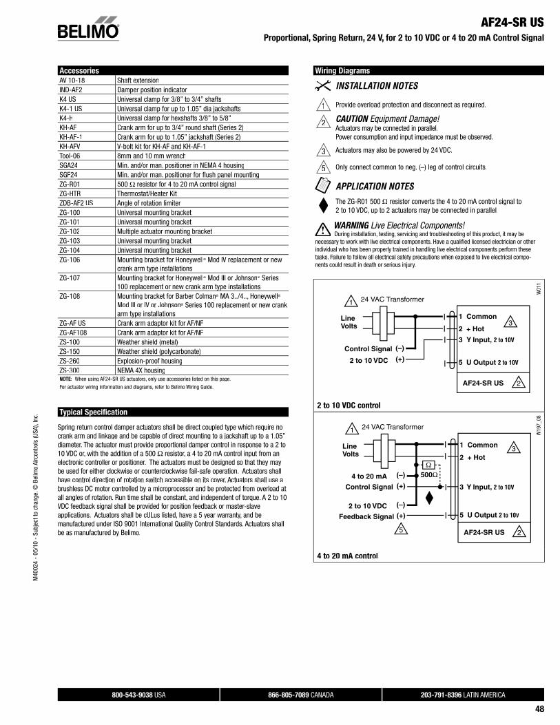
Wiring Diagrams
1 Provide overload protection and disconnect as required.
2 CAUTION Equipment Damage!Actuators may be connected in parallel.Power consumption and input impedance must be observed.
3 Actuators may also be powered by 24 VDC.
5 Only connect common to neg. (–) leg of control circuits.
The ZG-R01 500 Ω resistor converts the 4 to 20 mA control signal to2 to 10 VDC, up to 2 actuators may be connected in parallel.
WARNING Live Electrical Components!G During installation, testing, servicing and troubleshooting of this product, it may be
necessary to work with live electrical components. Have a qualifi ed licensed electrician or other individual who has been properly trained in handling live electrical components perform these tasks. Failure to follow all electrical safety precautions when exposed to live electrical compo-nents could result in death or serious injury.
Control Signal (+)2 to 10 VDC
(–)
1 Common
2 + Hot
3 Y Input, 2 to 10V
5 U Output 2 to 10V
1
2
3
24 VAC Transformer
AF24-SR US
Line Volts
W01
1
2 to 10 VDC control
W19
7_08
4 to 20 mA control
M40
024
- 05
/10
- Su
bjec
t to
chan
ge. ©
Bel
imo
Airc
ontro
ls (U
SA),
Inc.
800-543-9038 USA 866-805-7089 CANADA 203-791-8396 LATIN AMERICA
49
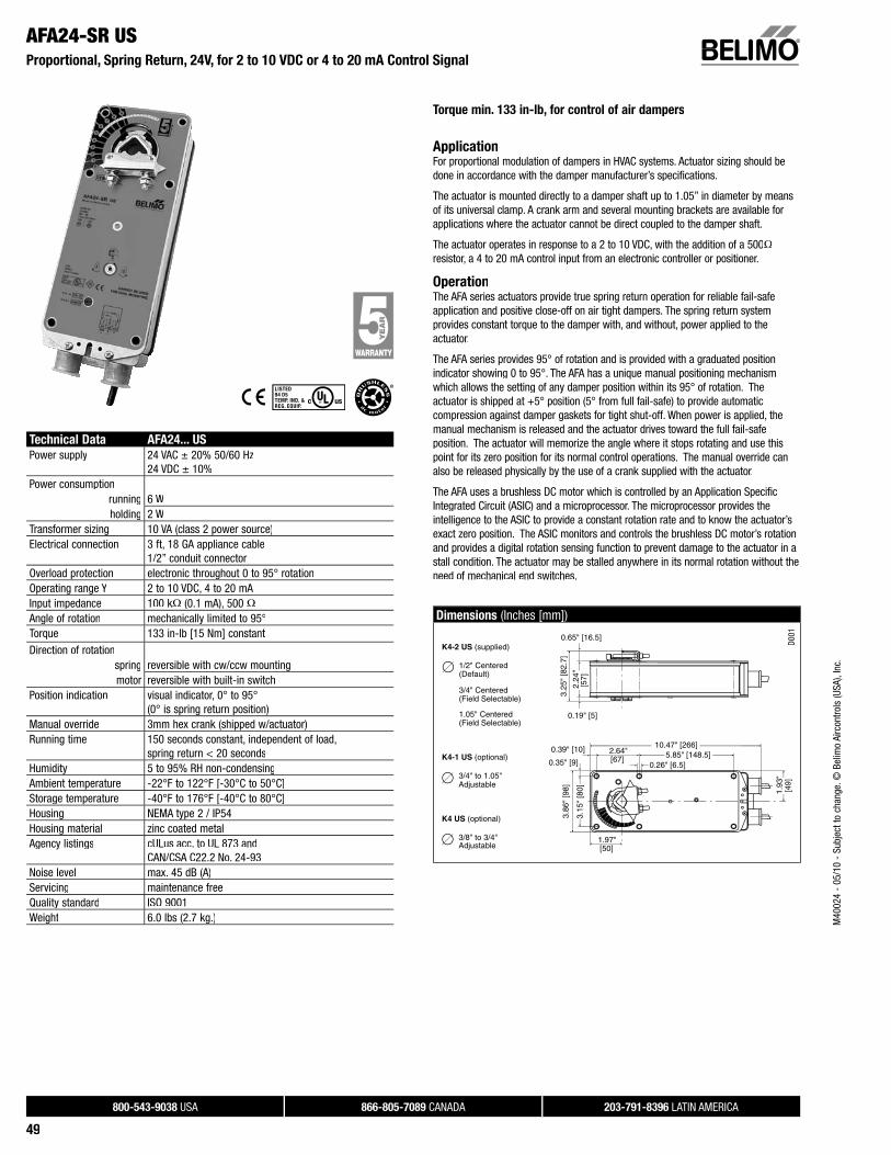
Torque min. 133 in-lb, for control of air dampers
ApplicationFor proportional modulation of dampers in HVAC systems. Actuator sizing should bedone in accordance with the damper manufacturer’s specifications.
The actuator is mounted directly to a damper shaft up to 1.05” in diameter by meansof its universal clamp. A crank arm and several mounting brackets are available forapplications where the actuator cannot be direct coupled to the damper shaft.
The actuator operates in response to a 2 to 10 VDC, with the addition of a 500Ωresistor, a 4 to 20 mA control input from an electronic controller or positioner.
OperationThe AFA series actuators provide true spring return operation for reliable fail-safeapplication and positive close-off on air tight dampers. The spring return system provides constant torque to the damper with, and without, power applied to the actuator.
The AFA series provides 95° of rotation and is provided with a graduated position indicator showing 0 to 95°. The AFA has a unique manual positioning mechanism which allows the setting of any damper position within its 95° of rotation. The actuator is shipped at +5° position (5° from full fail-safe) to provide automaticcompression against damper gaskets for tight shut-off. When power is applied, themanual mechanism is released and the actuator drives toward the full fail-safeposition. The actuator will memorize the angle where it stops rotating and use thispoint for its zero position for its normal control operations. The manual override canalso be released physically by the use of a crank supplied with the actuator.
The AFA uses a brushless DC motor which is controlled by an Application SpecificIntegrated Circuit (ASIC) and a microprocessor. The microprocessor provides theintelligence to the ASIC to provide a constant rotation rate and to know the actuator’s exact zero position. The ASIC monitors and controls the brushless DC motor’s rotationand provides a digital rotation sensing function to prevent damage to the actuator in astall condition. The actuator may be stalled anywhere in its normal rotation without theneed of mechanical end switches.
Dimensions (Inches [mm])
1.97"
3.15
" [8
0]
3.86
" [9
8]3.
25"
[82.
7]
2.24
" [5
7]
[50]
1.93
"[4
9]
2.64"[67]
0.26" [6.5]5.85" [148.5]
10.47" [266]
0.35" [9]
0.39" [10]
0.65" [16.5]
0.19" [5]
K4-2 US (supplied)
1/2" Centered (Default)
3/4" Centered (Field Selectable)
1.05" Centered (Field Selectable)
K4-1 US (optional)
3/4" to 1.05" Adjustable
K4 US (optional)
3/8" to 3/4" Adjustable
D001
AFA24-SR US Proportional, Spring Return, 24V, for 2 to 10 VDC or 4 to 20 mA Control Signal
Technical Data AFA24... US
Power supply 24 VAC ± 20% 50/60 Hz24 VDC ± 10%
Power consumptionrunning 6 Wholding 2 W
Transformer sizing 10 VA (class 2 power source)Electrical connection 3 ft, 18 GA appliance cable
1/2” conduit connectorOverload protection electronic throughout 0 to 95° rotationOperating range Y 2 to 10 VDC, 4 to 20 mA Input impedance 100 kΩ (0.1 mA), 500 ΩAngle of rotation mechanically limited to 95°Torque 133 in-lb [15 Nm] constant
Direction of rotationspring reversible with cw/ccw mountingmotor reversible with built-in switch
Position indication visual indicator, 0° to 95°(0° is spring return position)
Manual override 3mm hex crank (shipped w/actuator)Running time 150 seconds constant, independent of load,
spring return < 20 secondsHumidity 5 to 95% RH non-condensingAmbient temperature -22°F to 122°F [-30°C to 50°C]Storage temperature -40°F to 176°F [-40°C to 80°C]Housing NEMA type 2 / IP54Housing material zinc coated metalAgency listings cULus acc. to UL 873 and
CAN/CSA C22.2 No. 24-93Noise level max. 45 dB (A)Servicing maintenance freeQuality standard ISO 9001Weight 6.0 lbs (2.7 kg.) M
4002
4 -
05/1
0 -
Subj
ect t
o ch
ange
. © B
elim
o Ai
rcon
trols
(USA
), In
c.
800-543-9038 USA 866-805-7089 CANADA 203-791-8396 LATIN AMERICA
50
AFA24-SR USProportional, Spring Return, 24V, for 2 to 10 VDC or 4 to 20 mA Control Signal
Accessories
AV 10-18 Shaft extensionIND-AF2 Damper position indicatorK4 US Universal clamp for 3/8” to 3/4” shaftsK4-1 US Universal clamp for up to 1.05” dia jackshaftsK4-H Universal clamp for hexshafts 3/8” to 5/8”KH-AF Crank arm for up to 3/4” round shaft (Series 2)KH-AF-1 Crank arm for up to 1.05” jackshaft (Series 2)KH-AFV V-bolt kit for KH-AF and KH-AF-1Tool-06 8mm and 10 mm wrenchSGA24 Min. and/or man. positioner in NEMA 4 housingSGF24 Min. and/or man. positioner for flush panel mountingZG-R01 500 Ω resistor for 4 to 20 mA control signalZG-HTR Thermostat/Heater KitZDB-AF2 US Angle of rotation limiterZG-100 Universal mounting bracketZG-101 Universal mounting bracketZG-102 Multiple actuator mounting bracketZG-106 Mounting bracket for Honeywell® Mod IV replacement or new
crank arm type installationsZG-107 Mounting bracket for Honeywell® Mod III or Johnson® Series 100
replacement or new crank arm type installationsZG-108 Mounting bracket for Barber Colman® MA 3../4..,
Honeywell® Mod III or IV or Johnson® Series 100replacement or new crank arm type installations
ZG-AF US Crank arm adaptor kit for AF/NFZG-AF108 Crank arm adaptor kit for AF/NFZS-100 Weather shield (metal)ZS-150 Weather shield (polycarbonate)ZS-260 Explosion-proof housingZS-300 NEMA 4X housingNOTE: When using AFA24-SR US actuators, only use accessories listed on this page. Actuator may not be tandem mounted on same shaft or otherwise mechanically linked.
Typical Specification
Spring return control damper actuators shall be direct coupled type which re-quire no crank arm and linkage and be capable of direct mounting to a jack-shaft up to a 1.05” diameter. The actuator must provide proportional damper control in response to a 2 to 10 VDC or, with the addition of a 500Ω resistor,a 4 to 20 mA control input from an electronic controller or positioner. Theactuators must be designed so that they may be used for either clockwise or counterclockwise fail-safe operation. Actuators shall have control direction of rotation switch accessible on its cover. Actuators shall use a brushless DC motor controlled by a microprocessor and be protected from overload at all angles of rotation. Run time shall be constant, and independent of torque.Actuators shall be cULus listed, have a 5 year warranty, and be manufactured under ISO 9001 International Quality Control Standards. Actuators shall be as manufactured by Belimo.
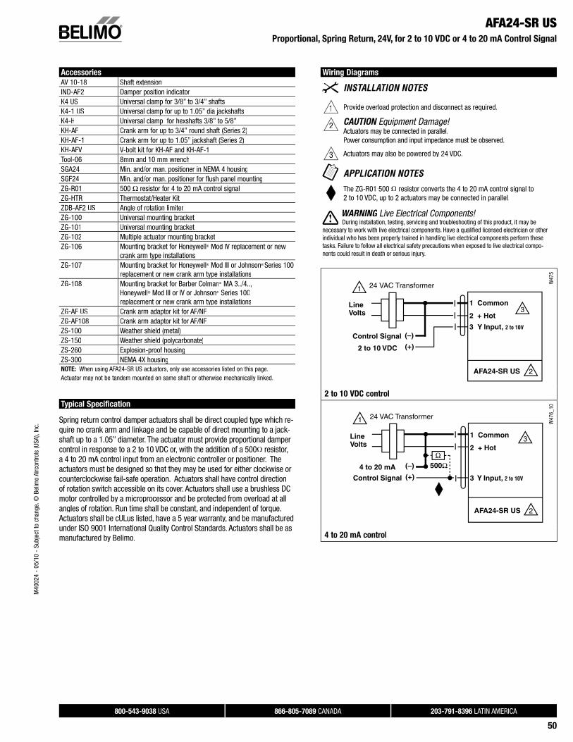
Wiring Diagrams
1 Provide overload protection and disconnect as required.
2 CAUTION Equipment Damage!Actuators may be connected in parallel.Power consumption and input impedance must be observed.
3 Actuators may also be powered by 24 VDC.
The ZG-R01 500 Ω resistor converts the 4 to 20 mA control signal to2 to 10 VDC, up to 2 actuators may be connected in parallel.
WARNING Live Electrical Components!G During installation, testing, servicing and troubleshooting of this product, it may be
necessary to work with live electrical components. Have a qualifi ed licensed electrician or other individual who has been properly trained in handling live electrical components perform these tasks. Failure to follow all electrical safety precautions when exposed to live electrical compo-nents could result in death or serious injury.
Control Signal (+)2 to 10 VDC
(–)
1 Common
2 + Hot
3 Y Input, 2 to 10V
1
2
3
24 VAC Transformer
AFA24-SR US
Line Volts
W47
5
2 to 10 VDC control
W47
6_10
4 to 20 mA control
M40
024
- 05
/10
- Su
bjec
t to
chan
ge. ©
Bel
imo
Airc
ontro
ls (U
SA),
Inc.