Embed Size (px)
Citation preview

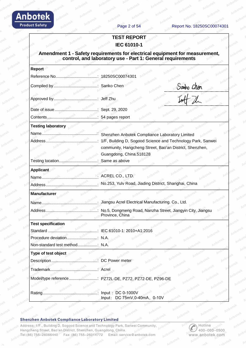
Report No.: 18250SC00074301
Test Report
Client Name : ACREL CO., LTD.
Address : No.253, Yulv Road, Jiading District, Shanghai, China
Product Name : DC Power meter
Date : Sept. 29, 2020
Shenzhen Anbotek Compliance Laboratory Limited
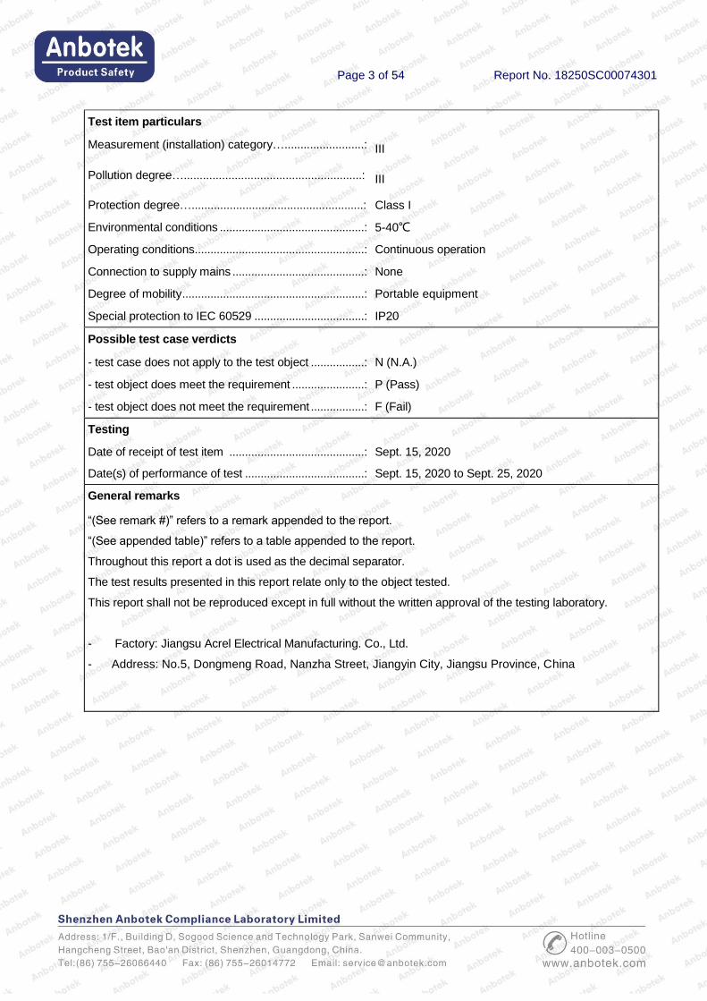
Page 2 of 54 Report No. 18250SC00074301
TEST REPORT
IEC 61010-1
Amendment 1 - Safety requirements for electrical equipment for measurement, control, and laboratory use - Part 1: General requirements
Report
Reference No. ..................................... : 18250SC00074301
Compiled by ........................................ : Sanko Chen
Approved by ........................................ : Jeff Zhu
Date of issue ....................................... : Sept. 29, 2020
Contents .............................................. : 54 pages report
Testing laboratory
Name ................................................... : Shenzhen Anbotek Compliance Laboratory Limited
Address ............................................... : 1/F, Building D, Sogood Science and Technology Park, Sanwei
community, Hangcheng Street, Bao'an District, Shenzhen,
Guangdong, China.518128
Testing location ................................... : Same as above
Applicant
Name ................................................... : ACREL CO., LTD.
Address ............................................... : No.253, Yulv Road, Jiading District, Shanghai, China
Manufacturer
Name ................................................... : Jiangsu Acrel Electrical Manufacturing. Co., Ltd.
Address ............................................... : No.5, Dongmeng Road, Nanzha Street, Jiangyin City, Jiangsu Province, China
Test specification
Standard ............................................. : IEC 61010-1: 2010+A1:2016
Procedure deviation ............................ : N.A.
Non-standard test method .................. : N.A.
Type of test object
Description .......................................... : DC Power meter
Trademark ........................................... : Acrel
Model/type reference .......................... : PZ72L-DE, PZ72, PZ72-DE, PZ96-DE
Rating .................................................. : Input :DC 0-1000V Input: DC 75mV,0-40mA,0-10V
Page 3 of 54 Report No. 18250SC00074301
Test item particulars
Measurement (installation) category….........................: III
Pollution degree…........................................................: III
Protection degree…......................................................: Class I
Environmental conditions ..............................................: 5-40℃
Operating conditions......................................................: Continuous operation
Connection to supply mains ..........................................: None
Degree of mobility ..........................................................: Portable equipment
Special protection to IEC 60529 ...................................: IP20
Possible test case verdicts
- test case does not apply to the test object .................: N (N.A.)
- test object does meet the requirement .......................: P (Pass)
- test object does not meet the requirement .................: F (Fail)
Testing
Date of receipt of test item ...........................................: Sept. 15, 2020
Date(s) of performance of test ......................................: Sept. 15, 2020 to Sept. 25, 2020
General remarks
“(See remark #)” refers to a remark appended to the report.
“(See appended table)” refers to a table appended to the report.
Throughout this report a dot is used as the decimal separator.
The test results presented in this report relate only to the object tested.
This report shall not be reproduced except in full without the written approval of the testing laboratory.
- Factory: Jiangsu Acrel Electrical Manufacturing. Co., Ltd.
- Address: No.5, Dongmeng Road, Nanzha Street, Jiangyin City, Jiangsu Province, China

Page 4 of 54 Report No. 18250SC00074301
Copy of marking plate
Formed as following:
DC Power meter
Model No: PZ72L-DE
Rating: Input :DC 0-1000V
Input: DC 75mV,0-40mA,0-10V
Jiangsu Acrel Electrical Manufacturing Co., Ltd.
No.5, Dongmeng Road, Nanzha Street, Jiangyin City, Jiangsu Province, China
Page 5 of 54 Report No. 18250SC00074301
IEC 61010-1
Clause Requirement – Test Result - Remark Verdict
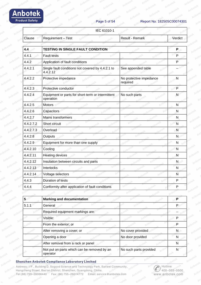
4.4 TESTING IN SINGLE FAULT CONDITION P
4.4.1 Fault tests P
4.4.2 Application of fault conditions P
4.4.2.1 Single fault conditions not covered by 4.4.2.1 to 4.4.2.12
See appended table --
4.4.2.2 Protective impedance No protective impedance required
N
4.4.2.3 Protective conductor P
4.4.2.4 Equipment or parts for short-term or intermittent operation
No such parts N
4.4.2.5 Motors N
4.4.2.6 Capacitors N
4.4.2.7 Mains transformers N
4.4.2.7.2 Short circuit N
4.4.2.7.3 Overload N
4.4.2.8 Outputs N
4.4.2.9 Equipment for more than one supply N
4.4.2.10 Cooling N
4.4.2.11 Heating devices N
4.4.2.12 Insulation between circuits and parts N
4.4.2.13 Interlocks N
4.4.2.14 Voltage selectors N
4.4.3 Duration of tests P
4.4.4 Conformity after application of fault conditions P
5 Marking and documentation P
5.1.1 General P
Required equipment markings are: --
Visible: P
From the exterior; or P
After removing a cover; or No cover provided N
Opening a door No door provided N
After removal from a rack or panel N
Not put on parts which can be removed by an operator
No such parts provided N
Page 6 of 54 Report No. 18250SC00074301
IEC 61010-1
Clause Requirement – Test Result - Remark Verdict
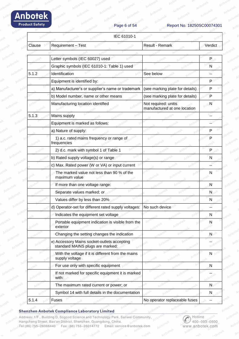
Letter symbols (IEC 60027) used P
Graphic symbols (IEC 61010-1: Table 1) used N
5.1.2 Identification See below --
Equipment is identified by: P
a) Manufacturer’s or supplier’s name or trademark (see marking plate for details) P
b) Model number, name or other means (see marking plate for details) P
Manufacturing location identified Not required: unitis manufactured at one location
N
5.1.3 Mains supply --
Equipment is marked as follows: --
a) Nature of supply: P
1) a.c. rated mains frequency or range of frequencies
P
2) d.c. mark with symbol 1 of Table 1 P
b) Rated supply voltage(s) or range N
c) Max. Rated power (W or VA) or input current --
The marked value not less than 90 % of the maximum value
N
If more than one voltage range: N
Separate values marked; or N
Values differ by less than 20% N
d) Operator-set for different rated supply voltages: No such device --
Indicates the equipment set voltage N
Portable equipment indication is visible from the exterior
N
Changing the setting changes the indication N
e) Accessory Mains socket-outlets accepting standard MAINS plugs are marked:
--
With the voltage if it is different from the mains supply voltage
N
For use only with specific equipment N
If not marked for specific equipment it is marked with:
--
The maximum rated current or power; or N
Symbol 14 with full details in the documentation N
5.1.4 Fuses No operator replaceable fuses --
Page 7 of 54 Report No. 18250SC00074301
IEC 61010-1
Clause Requirement – Test Result - Remark Verdict
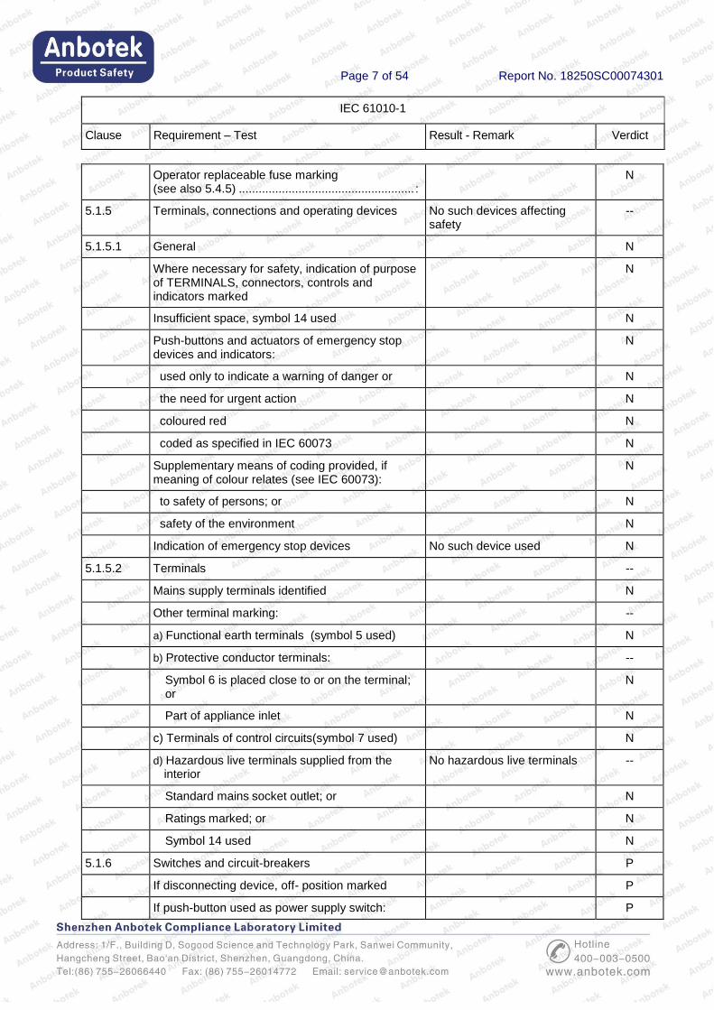
Operator replaceable fuse marking (see also 5.4.5) ..................................................... :
N
5.1.5 Terminals, connections and operating devices No such devices affecting safety
--
5.1.5.1 General N
Where necessary for safety, indication of purpose of TERMINALS, connectors, controls and indicators marked
N
Insufficient space, symbol 14 used N
Push-buttons and actuators of emergency stop devices and indicators:
N
used only to indicate a warning of danger or N
the need for urgent action N
coloured red N
coded as specified in IEC 60073 N
Supplementary means of coding provided, if meaning of colour relates (see IEC 60073):
N
to safety of persons; or N
safety of the environment N
Indication of emergency stop devices No such device used N
5.1.5.2 Terminals --
Mains supply terminals identified N
Other terminal marking: --
a) Functional earth terminals (symbol 5 used) N
b) Protective conductor terminals: --
Symbol 6 is placed close to or on the terminal; or
N
Part of appliance inlet N
c) Terminals of control circuits(symbol 7 used) N
d) Hazardous live terminals supplied from the interior
No hazardous live terminals --
Standard mains socket outlet; or N
Ratings marked; or N
Symbol 14 used N
5.1.6 Switches and circuit-breakers P
If disconnecting device, off- position marked P
If push-button used as power supply switch: P
Page 8 of 54 Report No. 18250SC00074301
IEC 61010-1
Clause Requirement – Test Result - Remark Verdict
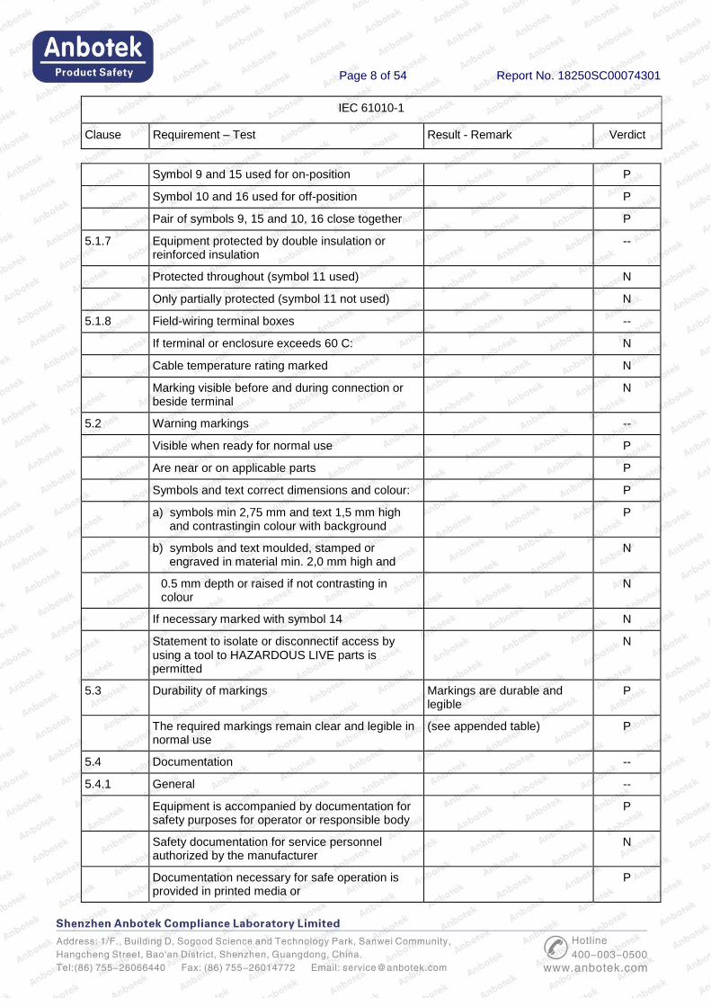
Symbol 9 and 15 used for on-position P
Symbol 10 and 16 used for off-position P
Pair of symbols 9, 15 and 10, 16 close together P
5.1.7 Equipment protected by double insulation or reinforced insulation
--
Protected throughout (symbol 11 used) N
Only partially protected (symbol 11 not used) N
5.1.8 Field-wiring terminal boxes --
If terminal or enclosure exceeds 60 C: N
Cable temperature rating marked N
Marking visible before and during connection or beside terminal
N
5.2 Warning markings --
Visible when ready for normal use P
Are near or on applicable parts P
Symbols and text correct dimensions and colour: P
a) symbols min 2,75 mm and text 1,5 mm high and contrastingin colour with background
P
b) symbols and text moulded, stamped or engraved in material min. 2,0 mm high and
N
0.5 mm depth or raised if not contrasting in colour
N
If necessary marked with symbol 14 N
Statement to isolate or disconnectif access by using a tool to HAZARDOUS LIVE parts is permitted
N
5.3 Durability of markings Markings are durable and legible
P
The required markings remain clear and legible in normal use
(see appended table) P
5.4 Documentation --
5.4.1 General --
Equipment is accompanied by documentation for safety purposes for operator or responsible body
P
Safety documentation for service personnel authorized by the manufacturer
N
Documentation necessary for safe operation is provided in printed media or
P

Page 9 of 54 Report No. 18250SC00074301
IEC 61010-1
Clause Requirement – Test Result - Remark Verdict
in electronic media if available at any time P
Documentation includes: --
a) Intended use P
b) Technical specification P
c) Name and address of manufacturer or supplier P
d) Information specified in 5.4.2 to 5.4.6 P
e) Information about how to mitigate risks remaining
P
f) accessories for safe operation of the equipment specified
P
g) guidance provided to check correct function of the equipment, if incorrect reading may cause a hazard from harmful or corrosive substances of hazardous live parts
N
h) Instructions for lifting and carrying (see 7.5) N
Warning statements and a clear explanation of warning symbols:
--
Provided in the documentation; or N
Information is marked on the equipment N
5.4.2 Equipment ratings --
Documentation includes: --
a) Supply voltage or voltage range AC 220V P
Frequency or frequency range N
Power or current rating P
b) Description of all input and output connections in accordance to 6.6.1 a)
P
c) Rating of insulation of external circuits as required by 6.6.1b)
N
d) Statement of the range of environmental conditions
Ambient temperature:
5℃~40℃
P
e) Degree of ingress protection (IP, IEC 60529) IP20 P
f) Impact rating less than 5 J No impact rating less than 5 J N
IK code in accordance to IEC 62262 marked or N
symbol 14 of table 1 marked, with N
RATED energy level and test method stated N
5.4.3 Equipment installation No special safety installation instructions deemed required
--
Page 10 of 54 Report No. 18250SC00074301
IEC 61010-1
Clause Requirement – Test Result - Remark Verdict
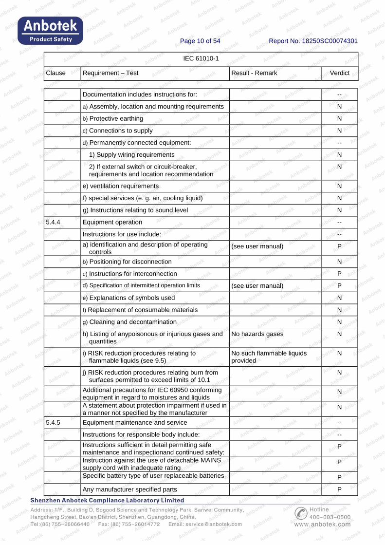
Documentation includes instructions for: --
a) Assembly, location and mounting requirements N
b) Protective earthing N
c) Connections to supply N
d) Permanently connected equipment: --
1) Supply wiring requirements N
2) If external switch or circuit-breaker, requirements and location recommendation
N
e) ventilation requirements N
f) special services (e. g. air, cooling liquid) N
g) Instructions relating to sound level N
5.4.4 Equipment operation --
Instructions for use include: --
a) identification and description of operating controls
(see user manual) P
b) Positioning for disconnection N
c) Instructions for interconnection P
d) Specification of intermittent operation limits (see user manual) P
e) Explanations of symbols used N
f) Replacement of consumable materials N
g) Cleaning and decontamination N
h) Listing of anypoisonous or injurious gases and quantities
No hazards gases N
i) RISK reduction procedures relating to flammable liquids (see 9.5)
No such flammable liquids provided
N
j) RISK reduction procedures relating burn from surfaces permitted to exceed limits of 10.1
N
Additional precautions for IEC 60950 conforming equipment in regard to moistures and liquids
N
A statement about protection impairment if used in a manner not specified by the manufacturer
N
5.4.5 Equipment maintenance and service --
Instructions for responsible body include: --
Instructions sufficient in detail permitting safe maintenance and inspectionand continued safety:
P
Instruction against the use of detachable MAINS supply cord with inadequate rating
P
Specific battery type of user replaceable batteries P
Any manufacturer specified parts P

Page 11 of 54 Report No. 18250SC00074301
IEC 61010-1
Clause Requirement – Test Result - Remark Verdict
Rating and characteristics of fuses P
Instructions include following subjects permitting safe servicing and continued safety:
P
a) product specificRISKSmay affect service personnel
P
b) protective measures for theseRISKS P
c) verification of the safe state after repair P
5.4.6 Integration into systems or effects resulting from special conditions
No such special conditions used
N
Aspects described in documentation N
6 Protection against electric shock --
6.1 General --
6.1.1 Requirements --
Protection against electric shock maintained in NORMAL CONDITION and SINGLE FAULT CONDITION
Comply with requirement P
ACCESSIBLE parts not HAZARDOUS LIVE P
Voltage, current, charge or energy below the limits in NORMAL CONDITION and in SINGLE FAULT CONDITION between:
P
ACCESSIBLE parts and earth N
Two ACCESSIBLE parts on same piece of the equipment within a distance of 1,8 m
P
Conformity is checked by the determination of 6.2 and 6.3 followed by the tests of 6.4 to 6.11
P
6.1.2 Exceptions --
Following HAZARDOUS LIVE parts may be accessible to an OPERATOR:
N
a) parts of lamps and lamp sockets after lamp removal
N
b) parts to be replaced by operator only by the use of tool and warning marking
N
Those parts not hazardous live 10 s after interruption of supply
N
Capacitance test if charge is received from internal capacitor
N
6.2 Determination of accessible parts --
6.2.1 General P

Page 12 of 54 Report No. 18250SC00074301
IEC 61010-1
Clause Requirement – Test Result - Remark Verdict
Unless obviously determination of accessible parts as specified in 6.2.2 to 6.2.4
P
6.2.2 Examination P
- with jointed test finger (as specified B.2) P
- with rigid test finger (as specified B.1) anda force of 10 N
P
6.2.3 Openings above parts that are hazardous live N
- test pin with length of 100 mm and 4 mm in diameter applied
N
6.2.4 Openings for pre-set controls N
- test pin with length of 100 mm and 3mm in diameter applied
N
6.3 Limit values for accessible parts --
6.3.1 Levels in normal condition P
a) Voltage limits less than 33 V r.m.s. and 46,7 V peak or 70 V d.c.
Accessible enclosure voltage limits less than 46,7 V peak or 70 V d.c.
P
for wet locations voltage limits less than 16 V r.m.s. and 22,6 V peak or 35 V d.c.
N
Voltages are not HAZARDOUS LIVE the levels of: --
b) Current less than 0,5 mA r.m.s. for sinusoidal, 0,7 mA peak non sinusoidal or mixed frequencies or 2 mA d.c. when measured with measuring circuit A.1 or A.2 if less than 100 Hz
Measure: 0.15mA r.m.s. P
for wet locations measuring circuit A.4 used N
c) Levels of capacitive charge or energy less: N
1) 45 µC for voltages up to 15 kV peak or d.c. or line A of Figure 3
N
2) 350 mJ stored energy for voltages above 15 kV peak or d.c.
N
6.3.2 Levels in single fault condition P
a) Voltage limits less than 33 V r.m.s. and 46,7 V peak or 70 V d.c.
Accessible enclosure voltage less than limit value
P
for wet locations voltage limits less than 16 V r.m.s. and 22,6 V peak or 35 V d.c.
N
Voltages are notHAZARDOUS LIVEthe levels of:
b) Current less than 0,5 mA r.m.s. for sinusoidal, 0,7 mA peak non sinusoidal or mixed frequencies or 2 mA d.c. when measured with measuring circuit A.1 or A.2 if less than 100 Hz
Measure: 0.15mA r.m.s. P
Page 13 of 54 Report No. 18250SC00074301
IEC 61010-1
Clause Requirement – Test Result - Remark Verdict
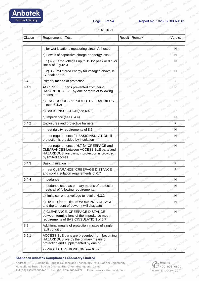
for wet locations measuring circuit A.4 used N
c) Levels of capacitive charge or energy less: N
1) 45 µC for voltages up to 15 kV peak or d.c. or line A of Figure 3
N
2) 350 mJ stored energy for voltages above 15 kV peak or d.c.
N
6.4 Primary means of protection --
6.4.1 ACCESSIBLE parts prevented from being HAZARDOUS LIVE by one or more of following means:
P
a) ENCLOSURES or PROTECTIVE BARRIERS (see 6.4.2)
P
b) BASIC INSULATION(see 6.4.3) P
c) Impedance (see 6.4.4) N
6.4.2 Enclosures and protective barriers P
- meet rigidity requirements of 8.1 N
- meet requirements for BASICINSULATION, if protection is provided by insulation
N
- meet requirements of 6.7 for CREEPAGE and CLEARANCES between ACCESSIBLE parts and HAZARDOUS live parts, if protection is provided by limited access
N
6.4.3 Basic insulation P
- meet CLEARANCE, CREEPAGE DISTANCE and solid insulation requirements of 6.7
P
6.4.4 Impedance N
Impedance used as primary means of protection meets all of following requirements:
N
a) limits current or voltage to level of 6.3.2 N
b) RATED for maximum WORKING VOLTAGE and the amount of power it will dissipate
N
c) CLEARANCE, CREEPAGE DISTANCE between terminations of the impedance meet requirements of BASICINSULATION of 6.7
N
6.5 Additional means of protection in case of single fault condition
--
6.5.1 ACCESSIBLE parts are prevented from becoming HAZARDOUS live by the primary means of protection and supplemented by one of:
--
a) PROTECTIVE BONDING(see 6.5.2) P
Page 14 of 54 Report No. 18250SC00074301
IEC 61010-1
Clause Requirement – Test Result - Remark Verdict
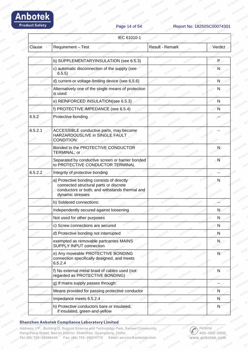
b) SUPPLEMENTARYINSULATION (see 6.5.3) P
c) automatic disconnection of the supply (see 6.5.5)
N
d) current-or voltage-limiting device (see 6.5.6) N
Alternatively one of the single means of protection is used:
N
e) REINFORCED INSULATION(see 6.5.3) N
f) PROTECTIVE IMPEDANCE (see 6.5.4) N
6.5.2 Protective bonding --
6.5.2.1 ACCESSIBLE conductive parts, may become HARZARDOUSLIVE in SINGLE FAULT CONDITION:
--
Bonded to the PROTECTIVE CONDUCTOR TERMINAL; or
N
Separated by conductive screen or barrier bonded to PROTECTIVE CONDUCTOR TERMINAL
N
6.5.2.2 Integrity of protective bonding --
a) Protective bonding consists of directly connected structural parts or discrete conductors or both; and withstands thermal and dynamic stresses
N
b) Soldered connections: --
Independently secured against loosening N
Not used for other purposes N
c) Screw connections are secured N
d) Protective bonding not interrupted N
exempted as removable partcarries MAINS SUPPLY INPUT connection
N
e) Any moveable PROTECTIVE BONDING connection specifically designed, and meets 6.5.2.4
N
f) No external metal braid of cables used (not regarded as PROTECTIVE BONDING)
N
g) If mains supply passes through: --
Means provided for passing protective conductor N
Impedance meets 6.5.2.4 N
h) Protective conductors bare or insulated, if insulated, green-and-yellow
N
Page 15 of 54 Report No. 18250SC00074301
IEC 61010-1
Clause Requirement – Test Result - Remark Verdict
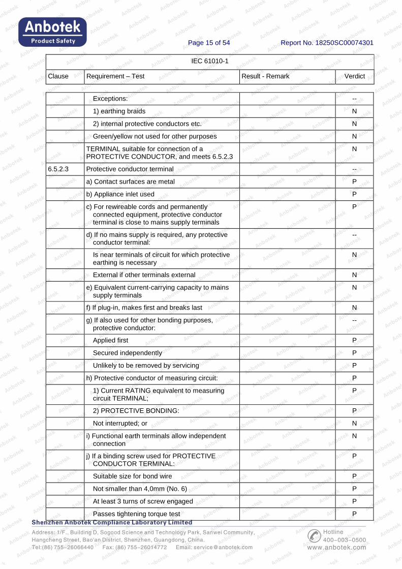
Exceptions: --
1) earthing braids N
2) internal protective conductors etc. N
Green/yellow not used for other purposes N
TERMINAL suitable for connection of a PROTECTIVE CONDUCTOR, and meets 6.5.2.3
N
6.5.2.3 Protective conductor terminal --
a) Contact surfaces are metal P
b) Appliance inlet used P
c) For rewireable cords and permanently connected equipment, protective conductor terminal is close to mains supply terminals
P
d) If no mains supply is required, any protective conductor terminal:
--
Is near terminals of circuit for which protective earthing is necessary
N
External if other terminals external N
e) Equivalent current-carrying capacity to mains supply terminals
N
f) If plug-in, makes first and breaks last N
g) If also used for other bonding purposes, protective conductor:
--
Applied first P
Secured independently P
Unlikely to be removed by servicing P
h) Protective conductor of measuring circuit: P
1) Current RATING equivalent to measuring circuit TERMINAL;
P
2) PROTECTIVE BONDING: P
Not interrupted; or N
i) Functional earth terminals allow independent connection
N
j) If a binding screw used for PROTECTIVE CONDUCTOR TERMINAL:
P
Suitable size for bond wire P
Not smaller than 4,0mm (No. 6) P
At least 3 turns of screw engaged P
Passes tightening torque test P
Page 16 of 54 Report No. 18250SC00074301
IEC 61010-1
Clause Requirement – Test Result - Remark Verdict
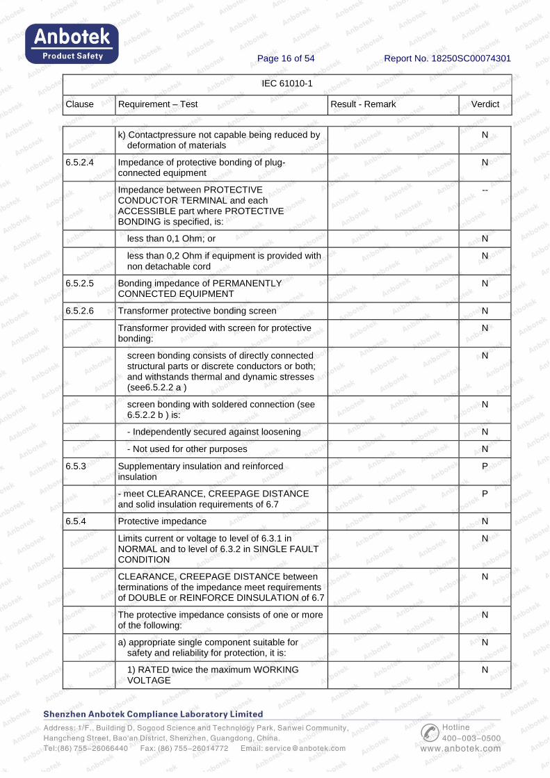
k) Contactpressure not capable being reduced by deformation of materials
N
6.5.2.4 Impedance of protective bonding of plug-connected equipment
N
Impedance between PROTECTIVE CONDUCTOR TERMINAL and each ACCESSIBLE part where PROTECTIVE BONDING is specified, is:
--
less than 0,1 Ohm; or N
less than 0,2 Ohm if equipment is provided with non detachable cord
N
6.5.2.5 Bonding impedance of PERMANENTLY CONNECTED EQUIPMENT
N
6.5.2.6 Transformer protective bonding screen N
Transformer provided with screen for protective bonding:
N
screen bonding consists of directly connected structural parts or discrete conductors or both; and withstands thermal and dynamic stresses (see6.5.2.2 a )
N
screen bonding with soldered connection (see 6.5.2.2 b ) is:
N
- Independently secured against loosening N
- Not used for other purposes N
6.5.3 Supplementary insulation and reinforced insulation
P
- meet CLEARANCE, CREEPAGE DISTANCE and solid insulation requirements of 6.7
P
6.5.4 Protective impedance N
Limits current or voltage to level of 6.3.1 in NORMAL and to level of 6.3.2 in SINGLE FAULT CONDITION
N
CLEARANCE, CREEPAGE DISTANCE between terminations of the impedance meet requirements of DOUBLE or REINFORCE DINSULATION of 6.7
N
The protective impedance consists of one or more of the following:
N
a) appropriate single component suitable for safety and reliability for protection, it is:
N
1) RATED twice the maximum WORKING VOLTAGE
N
Page 17 of 54 Report No. 18250SC00074301
IEC 61010-1
Clause Requirement – Test Result - Remark Verdict
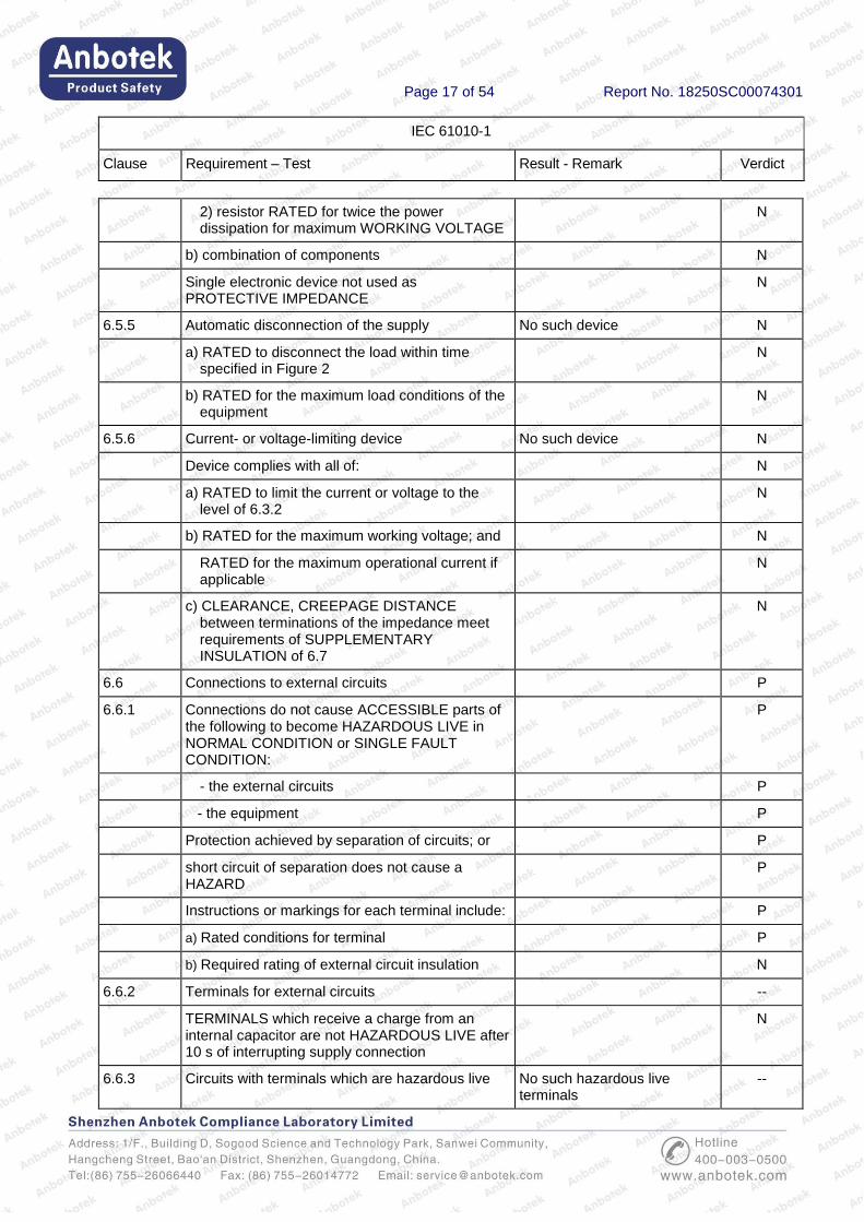
2) resistor RATED for twice the power dissipation for maximum WORKING VOLTAGE
N
b) combination of components N
Single electronic device not used as PROTECTIVE IMPEDANCE
N
6.5.5 Automatic disconnection of the supply No such device N
a) RATED to disconnect the load within time specified in Figure 2
N
b) RATED for the maximum load conditions of the equipment
N
6.5.6 Current- or voltage-limiting device No such device N
Device complies with all of: N
a) RATED to limit the current or voltage to the level of 6.3.2
N
b) RATED for the maximum working voltage; and N
RATED for the maximum operational current if applicable
N
c) CLEARANCE, CREEPAGE DISTANCE between terminations of the impedance meet requirements of SUPPLEMENTARY INSULATION of 6.7
N
6.6 Connections to external circuits P
6.6.1 Connections do not cause ACCESSIBLE parts of the following to become HAZARDOUS LIVE in NORMAL CONDITION or SINGLE FAULT CONDITION:
P
- the external circuits P
- the equipment P
Protection achieved by separation of circuits; or P
short circuit of separation does not cause a HAZARD
P
Instructions or markings for each terminal include: P
a) Rated conditions for terminal P
b) Required rating of external circuit insulation N
6.6.2 Terminals for external circuits --
TERMINALS which receive a charge from an internal capacitor are not HAZARDOUS LIVE after 10 s of interrupting supply connection
N
6.6.3 Circuits with terminals which are hazardous live No such hazardous live terminals
--
Page 18 of 54 Report No. 18250SC00074301
IEC 61010-1
Clause Requirement – Test Result - Remark Verdict
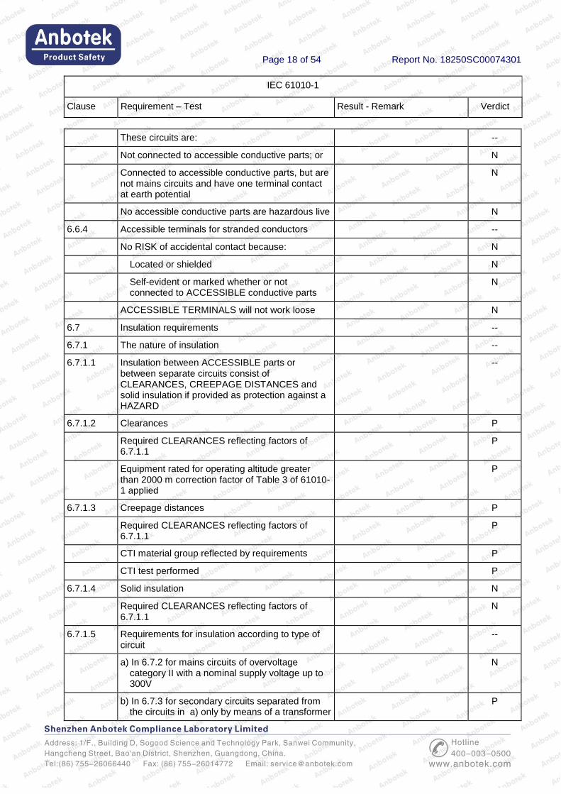
These circuits are: --
Not connected to accessible conductive parts; or N
Connected to accessible conductive parts, but are not mains circuits and have one terminal contact at earth potential
N
No accessible conductive parts are hazardous live N
6.6.4 Accessible terminals for stranded conductors --
No RISK of accidental contact because: N
Located or shielded N
Self-evident or marked whether or not connected to ACCESSIBLE conductive parts
N
ACCESSIBLE TERMINALS will not work loose N
6.7 Insulation requirements --
6.7.1 The nature of insulation --
6.7.1.1 Insulation between ACCESSIBLE parts or between separate circuits consist of CLEARANCES, CREEPAGE DISTANCES and solid insulation if provided as protection against a HAZARD
--
6.7.1.2 Clearances P
Required CLEARANCES reflecting factors of 6.7.1.1
P
Equipment rated for operating altitude greater than 2000 m correction factor of Table 3 of 61010-1 applied
P
6.7.1.3 Creepage distances P
Required CLEARANCES reflecting factors of 6.7.1.1
P
CTI material group reflected by requirements P
CTI test performed P
6.7.1.4 Solid insulation N
Required CLEARANCES reflecting factors of 6.7.1.1
N
6.7.1.5 Requirements for insulation according to type of circuit
--
a) In 6.7.2 for mains circuits of overvoltage category II with a nominal supply voltage up to 300V
N
b) In 6.7.3 for secondary circuits separated from the circuits in a) only by means of a transformer
P
Page 19 of 54 Report No. 18250SC00074301
IEC 61010-1
Clause Requirement – Test Result - Remark Verdict
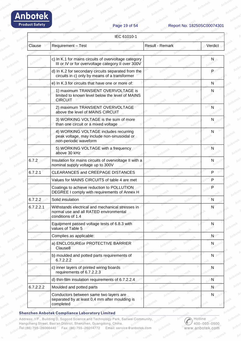
c) In K.1 for mains circuits of overvoltage category III or IV or for overvoltage category II over 300V
N
d) In K.2 for secondary circuits separated from the circuits in c) only by means of a transformer
P
e) In K.3 for circuits that have one or more of: N
1) maximum TRANSIENT OVERVOLTAGE is limited to known level below the level of MAINS CIRCUIT
N
2) maximum TRANSIENT OVERVOLTAGE above the level of MAINS CIRCUIT
N
3) WORKING VOLTAGE is the sum of more than one circuit or a mixed voltage
N
4) WORKING VOLTAGE includes recurring peak voltage, may include non-sinusoidal or non-periodic waveform
N
5) WORKING VOLTAGE with a frequency above 30 kHz
N
6.7.2 Insulation for mains circuits of overvoltage II with a nominal supply voltage up to 300V
N
6.7.2.1 CLEARANCES and CREEPAGE DISTANCES P
Values for MAINS CIRCUITS of table 4 are met P
Coatings to achieve reduction to POLLUTION DEGREE I comply with requirements of Annex H
P
6.7.2.2 Solid insulation N
6.7.2.2.1 Withstands electrical and mechanical stresses in normal use and all RATED environmental conditions of 1.4
N
Equipment passed voltage tests of 6.8.3 with values of Table 5
N
Complies as applicable: N
a) ENCLOSUREor PROTECTIVE BARRIER Clause8
N
b) moulded and potted parts requirements of 6.7.2.2.2
N
c) inner layers of printed wiring boards requirements of 6.7.2.2.3
N
d) thin-film insulation requirements of 6.7.2.2.4 N
6.7.2.2.2 Moulded and potted parts N
Conductors between same two layers are separated by at least 0,4 mm after moulding is completed
N
Page 20 of 54 Report No. 18250SC00074301
IEC 61010-1
Clause Requirement – Test Result - Remark Verdict
6.7.2.2.3 Inner insulation layers of printed wiring boards N
Separated by at least 0,4 mm between same two layers
N
REINFORCE DINSULATION have adequate electric strength; one of following methods used:
N
a) thickness at least 0,4 mm N
b) insulation is assembled of minimum two separate layers, each RATED for test voltage of Table 5 for BASIC INSULATION
N
c) insulation is assembled of minimum two separate layers, where the combination is rated for test voltage of Table 5 for REINFORCED INSULATION
N
6.7.2.2.4 Thin-film insulation N
Conductors between same two layers are separated by applicable CLEARANCES and CREEPAGE DISTANCES
N
REINFORCE DINSULATION have adequate electric strength; one of following methods used:
N
a) thickness at least 0,4 mm N
b) insulation is assembled of min two separate layers, each RATED for test voltage of Table 5 for BASIC INSULATION
N
c) insulation is assembled of min three separate layers, where the combination of two layers passed voltage tests of 6.8.3 with values of Table 5 for REINFORCED INSULATION
N
6.7.3 Insulation for secondeary circuits derived from mains circuits of overvoltage II with a nominal supply voltage up to 300V
N
6.7.3.1 Secondary circuits where separation from MAINS CIRCUITS is achieved by a transformer providing:
N
- REINFORCED INSULATION N
- DOUBLE INSULATION N
- screen connected to the PROTECTIVE CONDUCTOR TERMINAL
N
6.7.3.2 CLEARANCES P
a) meet the values of Table 6 for BASIC INSULATION and SUPPLEMENTARY INSULATION; or
P
twice the values of Table 6 for REINFORCED INSULATION
P
Page 21 of 54 Report No. 18250SC00074301
IEC 61010-1
Clause Requirement – Test Result - Remark Verdict
b) pass the voltage tests of 6.8 with values of Table 6; with following adjustments:
P
1) values forREINFORCED INSULATION are 1,6 times the values for BASIC INSULATION
P
2) if operating altitude is greater than 2000 m values of CLEARANCES multiplied with factor of Table 3
P
3) minimum CLEARANCE is 0,2 mm for POLLUTION DEGREE 2 and 0,8 mm for POLLUTION DEGREE 3
N
6.7.3.3 CREEPAGE DISTANCES P
Based on WORKING VOLTAGE meets the values of Table 7 for BASIC and SUPPLEMENTARY INSULATION
N
Values for REINFORCED INSULATION are twice the values of BASIC INSULATION
P
Coatings to achieve reduction to POLLUTION DEGREE I comply with requirements of Annex H
N
6.7.3.4 Solid insulation N
6.7.3.4.1 Withstands electrical and mechanical stresses in normal use and all RATED environmental conditions of 1.4
N
a) Equipment passed voltage test of 6.8.3.1 for 5 s with VALUES of Table 6 for BASIC and SUPPLEMENTARY INSULATION
N
values for REINFORCED INSULATION are 1,6 times the values of BASIC INSULATION
N
b) if WORKING VOLTAGE exceeds300 V, equipment passed voltage test of 6.8.3.1 for 1 min with a test voltage of 1,5 times working voltage for BASIC or SUPPLEMENTARY INSULATION
N
value for REINFORCED INSULATION are twice the WORKING VOLTAGE
N
Complies as applicable: N
1) ENCLOSURE or protective barrier Clause 8 N
2) moulded and potted parts requirements of 6.7.3.4.2
N
3) inner layers of printed wiring boards requirements of 6.7.3.4.3
N
4) thin-film insulation requirements of 6.7.3.4.4 N
6.7.3.4.2 Moulded and potted parts N

Page 22 of 54 Report No. 18250SC00074301
IEC 61010-1
Clause Requirement – Test Result - Remark Verdict
Conductors between same two layers are separated by applicable distancesof Table 8
N
6.7.3.4.3 Inner insulation layers of printed wiring boards N
Separated by at least by applicable distances of Table 8 between same two layers
N
REINFORCED INSULATION have adequate electric strength; one of following methods used:
N
a) thickness at least applicable distance of Table 8 N
b) insulation is assembled of minimum two separate layers, each RATED for test voltage of Table 6 for BASIC INSULATION
N
c) insulation is assembled of min two separate layers, where the combination is rated for 1,6 times the test voltage of Table 6
N
6.7.3.4.4 Thin-film insulation N
Conductors between same two layers are separated by applicable CLEARANCES andCREEPAGE DISTANCES
N
REINFORCED INSULATION have adequate electric strength; one of following methods used:
N
a) thickness at least applicable distance of Table 8 N
b) insulation is assembled of min two separate layers, each RATEDfor test voltage of Table 6 for BASIC INSULATION
N
c) insulation is assembled of min three separate layers, where the combination of two layers passed voltage tests with 1,6 time values of Table 6:
N
a.c. test of 6.8.3.1; or N
d.c. test of 6.8.3.2 for circuits stressed only by d.c. voltages
N
6.8 Procedure for voltage tests --
6.9 Constructional requirements for protection against electric shock
P
6.9.1 If a failure could cause a HAZARD: --
a) Security of wiring connections P
b) Screws securing removable covers P
c) Accidental loosening P
d) CREEPAGE and CLEARANCES not reduced below the values of basic insulation by loosening
P

Page 23 of 54 Report No. 18250SC00074301
IEC 61010-1
Clause Requirement – Test Result - Remark Verdict
6.9.2 Material not to be used for safety relevant insulation:
N
Easily damaged materials not used N
Non-impregnated hydroscopic materials not used N
6.9.3 Colour coding N
Green-and-yellow insulation shall not be used except:
--
a) protective earth conductors; N
b) protective bonding conductors; N
c) potential equilization conductors; N
d) functional earth conductors N
6.10 Connection to mains supply source and connections between parts of equipment
--
6.10.1 Mains supply cords --
Rated for maximum equipment current P
Cable complies with IEC 60227 or IEC 60245 P
Heat-resistant if likely to contact hot parts N
Temperature rating (cord and inlet) N
Green-and-yellow used only for connection to protective conductor terminals
P
Detachable cords with IEC 60320 mains connectors:
--
Conform to IEC 60799; or N
Have the current rating of the mains connector N
6.10.2 Fitting of non-detachable mains supply cords --
6.10.2.1 Cord entry --
Inlet or bushing smoothly rounded; or N
Insulated cord guard protruding >5D N
6.10.2.2 Cord anchorage: --
Protective earth conductor is the last to take the strain
N
a) Cord is not clamped by direct pressure from a screw
N
b) Knots are not used N
c) Cannot push the cord into the equipment to cause a hazard
N
Page 24 of 54 Report No. 18250SC00074301
IEC 61010-1
Clause Requirement – Test Result - Remark Verdict
d) No failure of cord insulation in anchorage with metal parts
N
e) Not to be loosened without a tool N
f) Cord replacement does not cause a HAZARD and method of strain relief is clear
N
Push-pull and or torque test N
6.10.3 Plugs and connectors --
Mains supply plugs, connectors etc., conform with relevant specifications
N
If equipment supplied at voltages below 6.3.2.a) or from a sole source:
N
Plugs of supply cords do not fit mains sockets above rated supply voltage
N
Mains-type plugs used only for connection to mains supply
N
Plug pins which receive a charge from an internal capacitor
N
Accessory MAINS socket outlets: N
a) Marking if accepts a standardMAINSplug (see 5.1.3e)
N
b) Input has a protective earth conductor if outlet has EARTH TERMINAL CONTACT
N
6.11 Disconnection from supply source --
6.11.1 Disconnects all current carrying conductors --
6.11.2 Exceptions --
6.11.3 Requirements according to type of equipment --
6.11.3.1 Permanently connected equipment and multi-phase equipment
N
Employs switch or circuit-breaker N
If switch or circuit-breaker is not part of the equipment, documentation requires:
--
a) Switch or circuit-breaker must be included in the installation
N
b) Suitable location easily reached N
c) Marking as disconnecting for the equipment N
6.11.3.2 Single-phase cord-connected equipment --
Equipment is provided with: --
a) Switch or circuit-breaker; or N
Page 25 of 54 Report No. 18250SC00074301
IEC 61010-1
Clause Requirement – Test Result - Remark Verdict
b) Appliance coupler (disconnectable without tool); N
c) Separable plug (without locking device) N
6.11.4 Disconnecting devices --
Electrically close to the SUPPLY N
6.11.4.1 Switches and circuit-breakers N
When used as disconnection device: N
Meets IEC 60947-1 and IEC 60947-3 N
Marked to indicate function....................................: N
Not incorporated in MAINS cord N
Does not interrupt PROTECTIVE EARTH CONDUCTOR
N
6.11.4.2 Appliance couplers and plugs --
Where an appliance coupler or separable plug is used as the disconnecting device (see 6.11.3.2):
--
Readily identifiable and easily reached by the operator
N
Single-phase portable equipment cord length not more than 3 m
N
Protective earth conductor connected first and disconnected last
N
7 Protection against mechanical hazards --
7.1 Equipment does not cause a mechanical HAZARD in NORMAL nor in SINGLE FAULT CONDITION
--
Conformity is checked by 7.2 to 7.7 P
7.2 Sharp edges Smooth and rounded P
Easily-touched parts are smooth and rounded P
Do not cause an injury in normal use and P
Do not cause an injury in single fault condition P
7.3 Moving parts --
7.3.1 HAZARDS from moving parts limited to a tolerable level with the conditions specified in 7.3.2 and 7.3.5
N
RISK assessment in accordance with 7.3.3 carried out
N
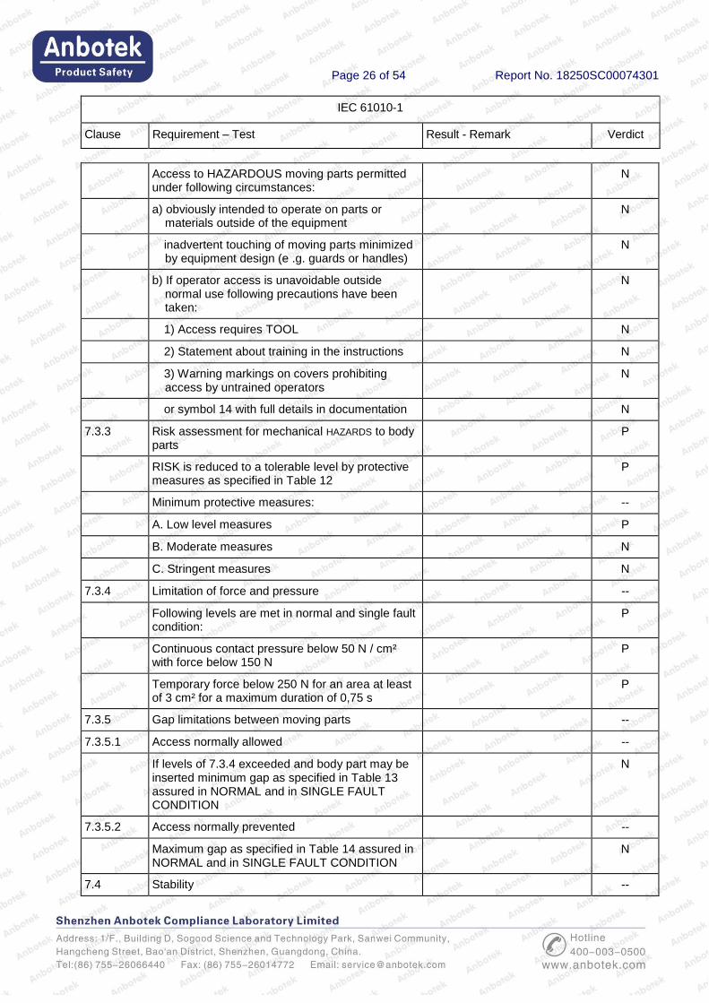
7.3.2 Exceptions: --
Page 26 of 54 Report No. 18250SC00074301
IEC 61010-1
Clause Requirement – Test Result - Remark Verdict
Access to HAZARDOUS moving parts permitted under following circumstances:
N
a) obviously intended to operate on parts or materials outside of the equipment
N
inadvertent touching of moving parts minimized by equipment design (e .g. guards or handles)
N
b) If operator access is unavoidable outside normal use following precautions have been taken:
N
1) Access requires TOOL N
2) Statement about training in the instructions N
3) Warning markings on covers prohibiting access by untrained operators
N
or symbol 14 with full details in documentation N
7.3.3 Risk assessment for mechanical HAZARDS to body parts
P
RISK is reduced to a tolerable level by protective measures as specified in Table 12
P
Minimum protective measures: --
A. Low level measures P
B. Moderate measures N
C. Stringent measures N
7.3.4 Limitation of force and pressure --
Following levels are met in normal and single fault condition:
P
Continuous contact pressure below 50 N / cm² with force below 150 N
P
Temporary force below 250 N for an area at least of 3 cm² for a maximum duration of 0,75 s
P
7.3.5 Gap limitations between moving parts --
7.3.5.1 Access normally allowed --
If levels of 7.3.4 exceeded and body part may be inserted minimum gap as specified in Table 13 assured in NORMAL and in SINGLE FAULT CONDITION
N
7.3.5.2 Access normally prevented --
Maximum gap as specified in Table 14 assured in NORMAL and in SINGLE FAULT CONDITION
N
7.4 Stability --

Page 27 of 54 Report No. 18250SC00074301
IEC 61010-1
Clause Requirement – Test Result - Remark Verdict
Equipment not secured to the building structure is physical stable
P
Stability maintained after opening of drawers, etc. By automatic means, or
N
Warning marking requires the application of means
N
Compliance checked by following tests as applicable:
--
a) 10° tilt test for other than handheld equipment P
b) multi-directional force test for equipment exceeds height of 1 m and mass of 25 kg
P
c) downward force test for floor-standing equipment
N
d) overload test with 4 times maximum load for castor or support that supports greatest load
N
e) castor or support that supports greatest load removed from equipment
N
7.5 Provisions for lifting and carrying P
7.5.1 Equipment more than 18 kg: Equipmentmass is way less than 18 kg
P
Has means for lifting or carrying; or P
Directions in documentation P
7.5.2 Handles or grips N
Handles or grips withstand four times weight N
7.5.3 Lifting devices and supporting parts N
Rated for maximum load; or N
tested with four times maximum static load N
7.6 Wall mounting Not a wall mounting equipment
--
Mounting brackets withstand four times weight N
7.7 Expelled parts No such expelled parts --
Equipment contains or limits the energy N
Protection not removable without the aid of a tool N
8 Resistance to mechanical stresses --
8.1 Equipment does not cause a hazard when subjected to mechanical stresses in normal use
P
Normal protection level is 5J Considered 5J P
Page 28 of 54 Report No. 18250SC00074301
IEC 61010-1
Clause Requirement – Test Result - Remark Verdict
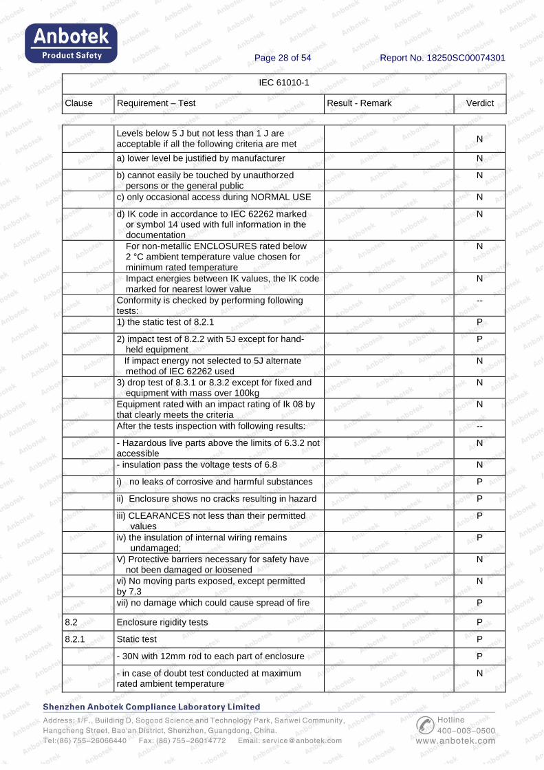
Levels below 5 J but not less than 1 J are acceptable if all the following criteria are met
N
a) lower level be justified by manufacturer N
b) cannot easily be touched by unauthorzed persons or the general public
N
c) only occasional access during NORMAL USE N
d) IK code in accordance to IEC 62262 marked or symbol 14 used with full information in the documentation
N
For non-metallic ENCLOSURES rated below 2 °C ambient temperature value chosen for minimum rated temperature
N
Impact energies between IK values, the IK code marked for nearest lower value
N
Conformity is checked by performing following tests:
--
1) the static test of 8.2.1 P
2) impact test of 8.2.2 with 5J except for hand-held equipment
P
If impact energy not selected to 5J alternate method of IEC 62262 used
N
3) drop test of 8.3.1 or 8.3.2 except for fixed and equipment with mass over 100kg
N
Equipment rated with an impact rating of Ik 08 by that clearly meets the criteria
N
After the tests inspection with following results: --
- Hazardous live parts above the limits of 6.3.2 not accessible
N
- insulation pass the voltage tests of 6.8 N
i) no leaks of corrosive and harmful substances P
ii) Enclosure shows no cracks resulting in hazard P
iii) CLEARANCES not less than their permitted values
P
iv) the insulation of internal wiring remains undamaged;
P
V) Protective barriers necessary for safety have not been damaged or loosened
N
vi) No moving parts exposed, except permitted by 7.3
N
vii) no damage which could cause spread of fire P
8.2 Enclosure rigidity tests P
8.2.1 Static test P
- 30N with 12mm rod to each part of enclosure P
- in case of doubt test conducted at maximum rated ambient temperature
N

Page 29 of 54 Report No. 18250SC00074301
IEC 61010-1
Clause Requirement – Test Result - Remark Verdict
8.2.2 Impact test P
Impact applied to any part of enclosure causing a hazard if damaged
P
Impact energy level and corresponding IK code…: P
Non-metallic enclosure cooled to minimum rated
ambient temperature if below 2℃
P
8.3 Drop test P
8.3.1 Equipment other than HAND-HELD EQUIPMENT and DIRECT PLUG-IN EQUIPMENT
P
Test conducted with a drop height or angle of..….: P
8.3.2 HAND-HELD EQUIPMENT and DIRECT PLUG-IN EQUIPMENT
N
Non-metallic ENCLOSURES cooled to minimum RATED ambient temperature if below 2 °C
N
Drop test conducted with an height of 1 m N
9 Protection against the spread of fire --
9.1 No spread of fire in normal and single fault condition
P
Mains supplied equipment meets requirement of 9.6 additionally
N
Conformity for each source of HAZARD or area of the equipment is checked by one of the following:
P
a) Fault test of 4.4; or P
b) Application of 9.2 (eliminating or reducing the sources of ignition); or
N
c) Application of 9.3 (containment of fire within the equipment)
P
9.2 Eliminating or reducing the sources of ignition within the equipment
--
a) 1) Limited-energy circuit (see 9.4); or N
2) Insulation meets the requirements for BASIC
INSULATION; OR N
Bridging the insulation does not cause ignition N
b) Any ignition HAZARD related to flammable liquids (see 9.5)
No liquids used N
c) No ignition in circuits designed to produce heat N
9.3 Containment of the fire within the equipment, should it occur
--

Page 30 of 54 Report No. 18250SC00074301
IEC 61010-1
Clause Requirement – Test Result - Remark Verdict
a) Energizing of the equipment is controlled by an operator held switch
N
b) ENCLOSURE is conform with constructional requirements of 9.3.1; and
P
Requirements of 9.5 are met N
9.3.1 Constructional requirements --
a) Connectors and insulating material have flammability classification V-2 or better
Fire enclosure is made of metal and plastic flame rated V-0
P
b) Insulated wires and cables are flame retardant (VW-1 or equivalent)
P
c) ENCLOSURE meets following requirements: P
1) Bottom and sides in arc of 5 ° (see Figure 13) to non-limited circuits (9.4) meets:
P
i) no openings; or P
ii) perforated as specified in Table 16; or N
iii) metal screen with a mesh; or N
iv) baffles as specified in Figure 12 N
2) Material of ENCLOSURE and any baffle or flame barrier is made of:
P
Metal (except magnesium); or P
Non-metallic materials have flammability classification V-1 or better
P
3) ENCLOSURE and any baffle or flame barrier have adequate rigidity
P
9.4 Limited-energy circuit --
a) Potential not more than 30 r.m.s. and 42.4 V peak, or 60 V dc
N
b) Current limited by one of following means: --
1) Inherently or by impedance; N
2) Over current protective device; N
3) A regulating network limits also in SINGLE FAULT CONDITION
N
c) Is separated by at least BASIC INSULATION N
Fuse or a nonadjustable electromechanical device is used
N
9.5 Requirements for equipment containing or using flammable liquids
No flammable liquids used N
Page 31 of 54 Report No. 18250SC00074301
IEC 61010-1
Clause Requirement – Test Result - Remark Verdict
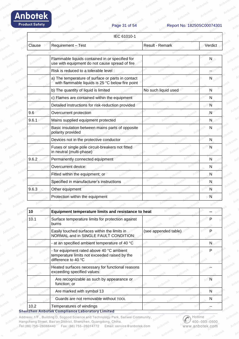
Flammable liquids contained in or specified for use with equipment do not cause spread of fire
N
Risk is reduced to a tolerable level : --
a) The temperature of surface or parts in contact with flammable liquids is 25 °C below fire point
N
b) The quantity of liquid is limited No such liquid used N
c) Flames are contained within the equipment N
Detailed instructions for risk-reduction provided N
9.6 Overcurrent protection N
9.6.1 Mains supplied equipment protected N
Basic insulation between mains parts of opposite polarity provided
N
Devices not in the protective conductor N
Fuses or single pole circuit-breakers not fitted in neutral (multi-phase)
N
9.6.2 Permanently connected equipment N
Overcurrent device: N
Fitted within the equipment; or N
Specified in manufacturer’s instructions N
9.6.3 Other equipment N
Protection within the equipment N
10 Equipment temperature limits and resistance to heat --
10.1 Surface temperature limits for protection against burns
P
Easily touched surfaces within the limits in NORMAL and in SINGLE FAULT CONDITION:
(see appended table) P
- at an specified ambient temperature of 40 °C N
- for equipment rated above 40 °C ambient temperature limits not exceeded raised by the difference to 40 °C
P
Heated surfaces necessary for functional reasons exceeding specified values:
--
Are recognizable as such by appearance or function; or
N
Are marked with symbol 13 N
Guards are not removable without TOOL N
10.2 Temperatures of windings --
Page 32 of 54 Report No. 18250SC00074301
IEC 61010-1
Clause Requirement – Test Result - Remark Verdict
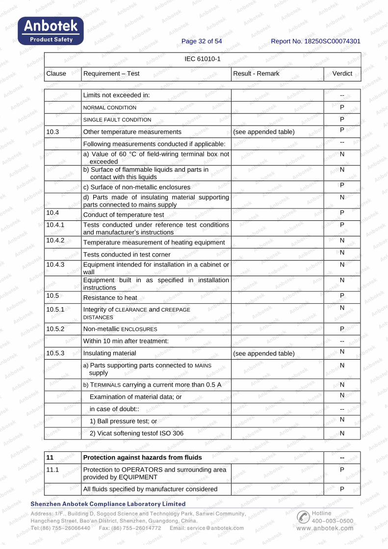
Limits not exceeded in: --
NORMAL CONDITION P
SINGLE FAULT CONDITION P
10.3 Other temperature measurements (see appended table) P
Following measurements conducted if applicable: --
a) Value of 60 °C of field-wiring terminal box not exceeded
N
b) Surface of flammable liquids and parts in contact with this liquids
N
c) Surface of non-metallic enclosures P
d) Parts made of insulating material supporting parts connected to mains supply
N
10.4 Conduct of temperature test P
10.4.1 Tests conducted under reference test conditions and manufacturer’s instructions
P
10.4.2 Temperature measurement of heating equipment N
Tests conducted in test corner N
10.4.3 Equipment intended for installation in a cabinet or wall
N
Equipment built in as specified in installation instructions
N
10.5 Resistance to heat P
10.5.1 Integrity of CLEARANCE and CREEPAGE DISTANCES
N
10.5.2 Non-metallic ENCLOSURES P
Within 10 min after treatment: --
10.5.3 Insulating material (see appended table) N
a) Parts supporting parts connected to MAINS supply
N
b) TERMINALS carrying a current more than 0.5 A N
Examination of material data; or N
in case of doubt:: --
1) Ball pressure test; or N
2) Vicat softening testof ISO 306 N
11 Protection against hazards from fluids --
11.1 Protection to OPERATORS and surrounding area provided by EQUIPMENT
P
All fluids specified by manufacturer considered P
Page 33 of 54 Report No. 18250SC00074301
IEC 61010-1
Clause Requirement – Test Result - Remark Verdict
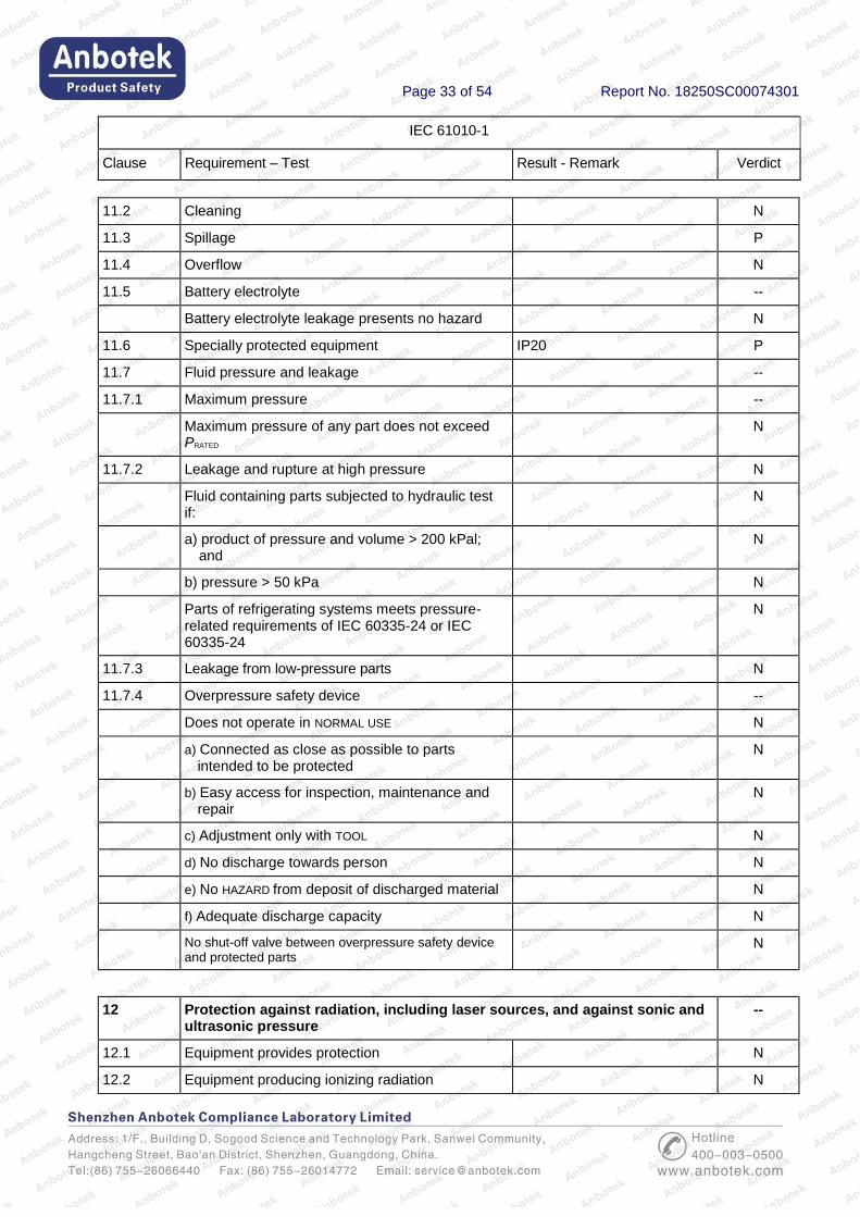
11.2 Cleaning N
11.3 Spillage P
11.4 Overflow N
11.5 Battery electrolyte --
Battery electrolyte leakage presents no hazard N
11.6 Specially protected equipment IP20 P
11.7 Fluid pressure and leakage --
11.7.1 Maximum pressure --
Maximum pressure of any part does not exceed PRATED
N
11.7.2 Leakage and rupture at high pressure N
Fluid containing parts subjected to hydraulic test if:
N
a) product of pressure and volume > 200 kPal; and
N
b) pressure > 50 kPa N
Parts of refrigerating systems meets pressure-related requirements of IEC 60335-24 or IEC 60335-24
N
11.7.3 Leakage from low-pressure parts N
11.7.4 Overpressure safety device --
Does not operate in NORMAL USE N
a) Connected as close as possible to parts intended to be protected
N
b) Easy access for inspection, maintenance and repair
N
c) Adjustment only with TOOL N
d) No discharge towards person N
e) No HAZARD from deposit of discharged material N
f) Adequate discharge capacity N
No shut-off valve between overpressure safety device and protected parts
N
12 Protection against radiation, including laser sources, and against sonic and ultrasonic pressure
--
12.1 Equipment provides protection N
12.2 Equipment producing ionizing radiation N
Page 34 of 54 Report No. 18250SC00074301
IEC 61010-1
Clause Requirement – Test Result - Remark Verdict
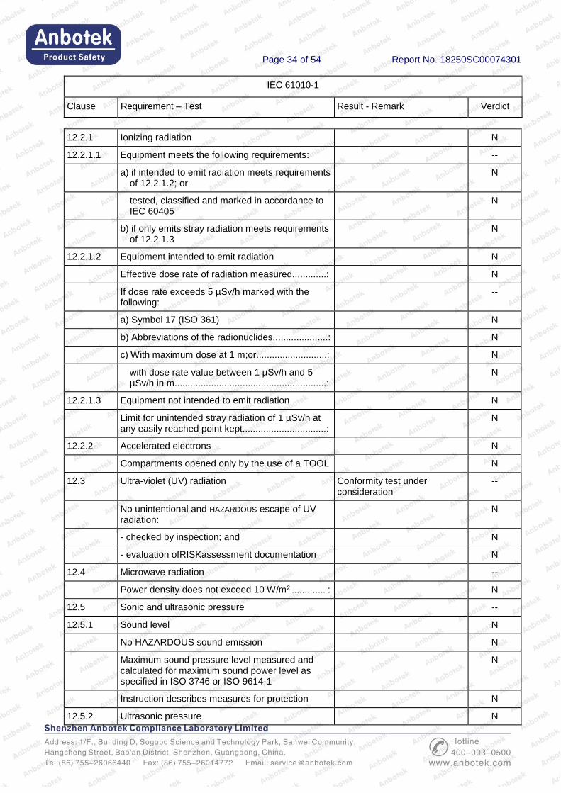
12.2.1 Ionizing radiation N
12.2.1.1 Equipment meets the following requirements: --
a) if intended to emit radiation meets requirements of 12.2.1.2; or
N
tested, classified and marked in accordance to IEC 60405
N
b) if only emits stray radiation meets requirements of 12.2.1.3
N
12.2.1.2 Equipment intended to emit radiation N
Effective dose rate of radiation measured.............: N
If dose rate exceeds 5 µSv/h marked with the following:
--
a) Symbol 17 (ISO 361) N
b) Abbreviations of the radionuclides.....................: N
c) With maximum dose at 1 m;or...........................: N
with dose rate value between 1 µSv/h and 5 µSv/h in m..........................................................:
N
12.2.1.3 Equipment not intended to emit radiation N
Limit for unintended stray radiation of 1 µSv/h at any easily reached point kept................................:
N
12.2.2 Accelerated electrons N
Compartments opened only by the use of a TOOL N
12.3 Ultra-violet (UV) radiation Conformity test under consideration
--
No unintentional and HAZARDOUS escape of UV radiation:
N
- checked by inspection; and N
- evaluation ofRISKassessment documentation N
12.4 Microwave radiation --
Power density does not exceed 10 W/m2 ............. : N
12.5 Sonic and ultrasonic pressure --
12.5.1 Sound level N
No HAZARDOUS sound emission N
Maximum sound pressure level measured and calculated for maximum sound power level as specified in ISO 3746 or ISO 9614-1
N
Instruction describes measures for protection N
12.5.2 Ultrasonic pressure N
Page 35 of 54 Report No. 18250SC00074301
IEC 61010-1
Clause Requirement – Test Result - Remark Verdict
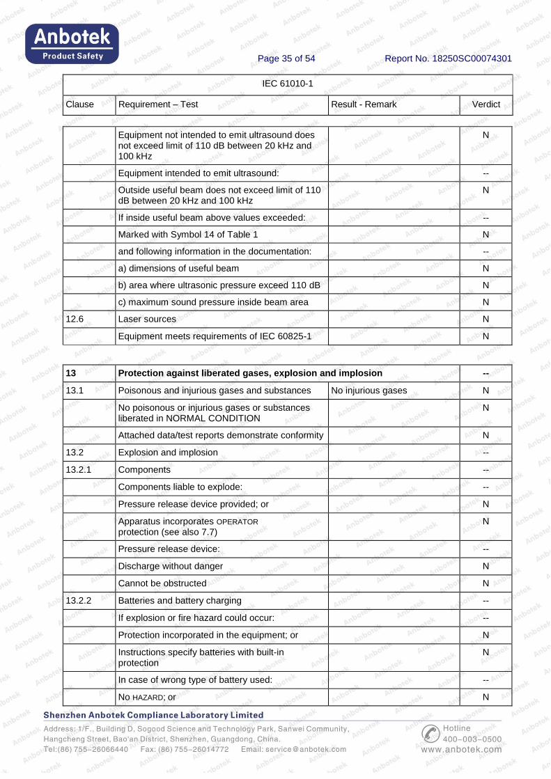
Equipment not intended to emit ultrasound does not exceed limit of 110 dB between 20 kHz and 100 kHz
N
Equipment intended to emit ultrasound: --
Outside useful beam does not exceed limit of 110 dB between 20 kHz and 100 kHz
N
If inside useful beam above values exceeded: --
Marked with Symbol 14 of Table 1 N
and following information in the documentation: --
a) dimensions of useful beam N
b) area where ultrasonic pressure exceed 110 dB N
c) maximum sound pressure inside beam area N
12.6 Laser sources N
Equipment meets requirements of IEC 60825-1 N
13 Protection against liberated gases, explosion and implosion --
13.1 Poisonous and injurious gases and substances No injurious gases N
No poisonous or injurious gases or substances liberated in NORMAL CONDITION
N
Attached data/test reports demonstrate conformity N
13.2 Explosion and implosion --
13.2.1 Components --
Components liable to explode: --
Pressure release device provided; or N
Apparatus incorporates OPERATOR protection (see also 7.7)
N
Pressure release device: --
Discharge without danger N
Cannot be obstructed N
13.2.2 Batteries and battery charging --
If explosion or fire hazard could occur: --
Protection incorporated in the equipment; or N
Instructions specify batteries with built-in protection
N
In case of wrong type of battery used: --
No HAZARD; or N

Page 36 of 54 Report No. 18250SC00074301
IEC 61010-1
Clause Requirement – Test Result - Remark Verdict
Warning by marking and within instructions N
Equipment with means to charge rechargeable batteries:
--
Warning against the charging of non-rechargeable batteries; and
N
Type of rechargeable battery indicated; or N
Symbol 14 used N
Battery compartment design N
Single component failure N
Polarity reversal test N
13.2.3 Implosion of cathode ray tubes No such device used --
If maximum face dimensions > 160 mm: --
Intrinsically protected and correctly mounted; or N
ENCLOSURE provides protection: N
If non-intrinsically protected: --
Screen not removable without TOOL N
If glass screen, not in contact with surface of tube N
14 Components and subassemblies P
14.1 Where safety is involved, components meet relevant requirements
Components used in accordance with their specified ratings and comply with relevant IEC standard
P
14.2 Motors --
14.2.1 Motor temperatures --
Does not present a HAZARD when stopped or prevented form starting; or
No Hazard N
Protected by overtemperature or thermal protection device conform with 14.3
N
14.2.2 Series excitation motors --
Connected direct to device, if overspeeding causes a HAZARD
N
14.3 Overtemperature protection devices N
Devices operating in a SINGLE FAULT CONDITION N
a) Reliable function is ensured N
b) RATED to interrupt maximum current and voltage
N

Page 37 of 54 Report No. 18250SC00074301
IEC 61010-1
Clause Requirement – Test Result - Remark Verdict
c) Does not operate in NORMAL USE N
If self-resetting device used to prevent HAZARD, protected part requires intervention before restarting
N
14.4 Fuse holders N
No access to HAZARDOUS LIVE parts N
14.5 Mains voltage selecting devices No selecting devices used N
Accidental change not possible N
14.6 Mains transformers tested outside equipment N
14.7 Printed wiring boards P
Data shows conformity with V-1 of IEC 60695-11-10 or better; or
P
Test shows conformity with V-1 of IEC 60695-11-10 or better
N
Not applicable for printed wiring boards with limited-energy circuits (9.4)
N
14.8 Circuits or components used as TRANSIENT
OVERVOLTAGE limiting devices N
Test conducted between each pair of MAINS SUPPLY TERMINALS
N
No HAZARD resulting from rupture or overheating of the component:
N
- no bridging of safety relevant insulation N
- no heat to other parts above the self-ignition points
N
15 Protection by interlocks --
15.1 Interlocks are designed to remove a hazard before OPERATOR exposed
N
15.2 Prevention of reactivating N
15.3 Reliability --
Single fault unlikely to occur; or N
Cannot cause a HAZARD N
16 HAZARDS resulting from application P
16.1 REASONABLY FORESEEABLE MISUSE P
No hazards arising from setting not intended and not described in the instructions
P
Page 38 of 54 Report No. 18250SC00074301
IEC 61010-1
Clause Requirement – Test Result - Remark Verdict
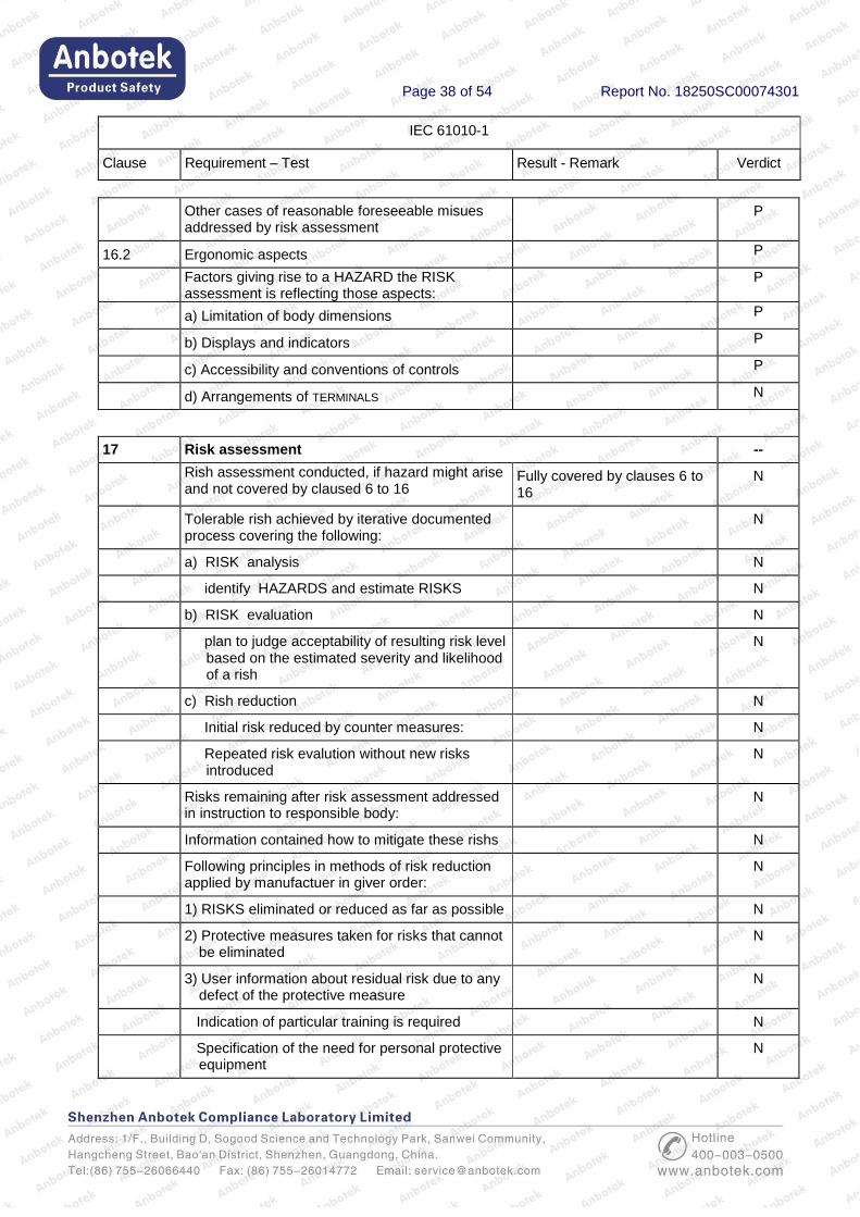
Other cases of reasonable foreseeable misues addressed by risk assessment
P
16.2 Ergonomic aspects P
Factors giving rise to a HAZARD the RISK assessment is reflecting those aspects:
P
a) Limitation of body dimensions P
b) Displays and indicators P
c) Accessibility and conventions of controls P
d) Arrangements of TERMINALS N
17 Risk assessment --
Rish assessment conducted, if hazard might arise and not covered by claused 6 to 16
Fully covered by clauses 6 to 16
N
Tolerable rish achieved by iterative documented process covering the following:
N
a) RISK analysis N
identify HAZARDS and estimate RISKS N
b) RISK evaluation N
plan to judge acceptability of resulting risk level based on the estimated severity and likelihood of a rish
N
c) Rish reduction N
Initial risk reduced by counter measures: N
Repeated risk evalution without new risks introduced
N
Risks remaining after risk assessment addressed in instruction to responsible body:
N
Information contained how to mitigate these rishs N
Following principles in methods of risk reduction applied by manufactuer in giver order:
N
1) RISKS eliminated or reduced as far as possible N
2) Protective measures taken for risks that cannot be eliminated
N
3) User information about residual risk due to any defect of the protective measure
N
Indication of particular training is required N
Specification of the need for personal protective equipment
N
Page 39 of 54 Report No. 18250SC00074301
IEC 61010-1
Clause Requirement – Test Result - Remark Verdict
Conformity checked by evaluation of the risk assessment documentation
N
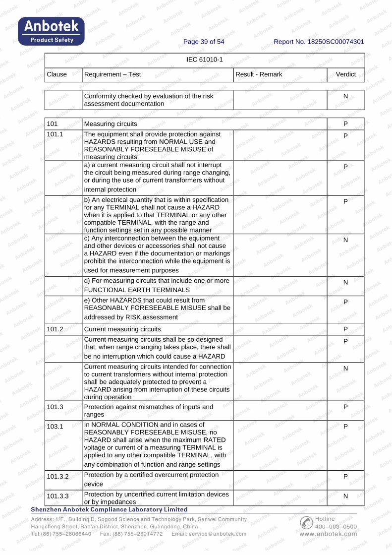
101 Measuring circuits P
101.1 The equipment shall provide protection against HAZARDS resulting from NORMAL USE and REASONABLY FORESEEABLE MISUSE of measuring circuits,
P
a) a current measuring circuit shall not interrupt the circuit being measured during range changing, or during the use of current transformers without
internal protection
P
b) An electrical quantity that is within specification for any TERMINAL shall not cause a HAZARD when it is applied to that TERMINAL or any other compatible TERMINAL, with the range and function settings set in any possible manner
P
c) Any interconnection between the equipment and other devices or accessories shall not cause a HAZARD even if the documentation or markings prohibit the interconnection while the equipment is
used for measurement purposes
N
d) For measuring circuits that include one or more
FUNCTIONAL EARTH TERMINALS N
e) Other HAZARDS that could result from REASONABLY FORESEEABLE MISUSE shall be
addressed by RISK assessment
P
101.2 Current measuring circuits P
Current measuring circuits shall be so designed that, when range changing takes place, there shall
be no interruption which could cause a HAZARD
P
Current measuring circuits intended for connection to current transformers without internal protection shall be adequately protected to prevent a HAZARD arising from interruption of these circuits during operation
N
101.3 Protection against mismatches of inputs and ranges
P
103.1 In NORMAL CONDITION and in cases of REASONABLY FORESEEABLE MISUSE, no HAZARD shall arise when the maximum RATED voltage or current of a measuring TERMINAL is applied to any other compatible TERMINAL, with
any combination of function and range settings
P
101.3.2 Protection by a certified overcurrent protection
device P
101.3.3 Protection by uncertified current limitation devices or by impedances
N
Page 40 of 54 Report No. 18250SC00074301
IEC 61010-1
Clause Requirement – Test Result - Remark Verdict
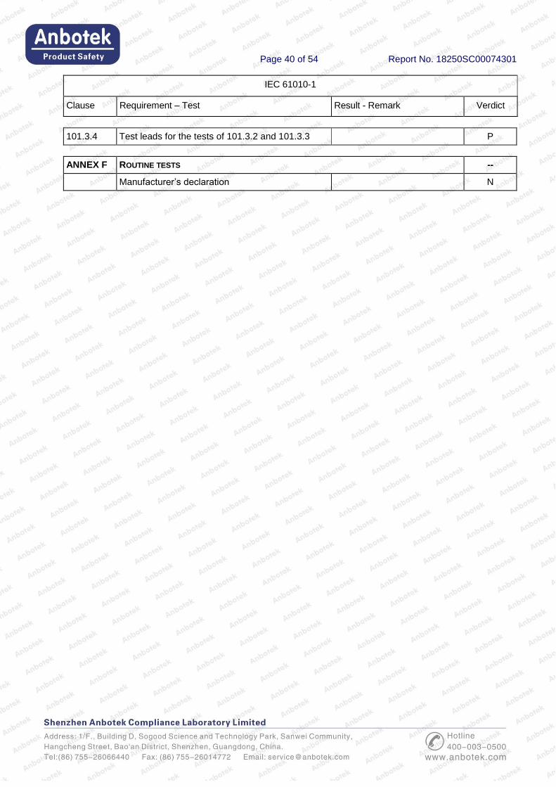
101.3.4 Test leads for the tests of 101.3.2 and 101.3.3 P
ANNEX F ROUTINE TESTS --
Manufacturer’s declaration N
Page 41 of 54 Report No. 18250SC00074301
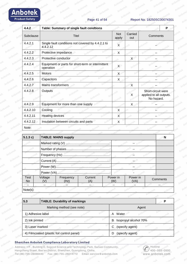
4.4.2 Table: Summary of single fault condtions P
Subclause Titel Not
apply
Carried
out Comments
4.4.2.1 Single fault conditions not covered by 4.4.2.1 to 4.4.2.12
X --
4.4.2.2 Protective impedance X --
4.4.2.3 Protective conductor X --
4.4.2.4 Equipment or parts for short-term or intermittent operation
X --
4.4.2.5 Motors X --
4.4.2.6 Capacitors X --
4.4.2.7 Mains transformers X --
4.4.2.8 Outputs
X
Short-circuit were
applied to all outputs.
No hazard.
4.4.2.9 Equipment for more than one supply X --
4.4.2.10 Cooling X --
4.4.2.11 Heating devices X --
4.4.2.12 Insulation between circuits and parts X --
Note:
5.1.3 c) TABLE: MAINS supply N
Marked rating (V) ..................................................... : --
Number of phases .................................................... : --
Frequency (Hz) ........................................................ : --
Current (A) ................................................................ : --
Power (W)................................................................. : --
Power (VA) ............................................................... : -
Test No
Voltage (V)
Frequency (Hz)
Current (A)
Power in (W)
Power in (VA)
Comments
-- -- -- -- -- -- --
Note(s):
5.3 TABLE: Durability of markings P
Marking method (see note) Agent
1) Adhesive label A Water
2) Ink printed B Isopropyl alcohol 70%
3) Laser marked C (specify agent)
4) Filmcoated (plastic foil control panel) D (specify agent)

Page 42 of 54 Report No. 18250SC00074301
5) Imprint on plastic (moulded in)
E (specify agent)
Note(s): Where applicable include print method, label material, ink or paint type, fixing method, adhesive and surface to which marking is fixed.
Marking location Marking method (see above)
- Identification (5.1.2) ............................................... : 1
- Mains supply (5.1.3)............................................... : 1
- Fuses (5.1.4) .......................................................... :
- Terminals, connections and operating devices
(5.1.5) ....................................................................... :
1
- Switches and circuit-breakers(5.1.6)
- Double/reinforced equipment (5.1.7) .................... :
- Field-wiring TERMINAL boxes (5.1.8) ................. :
- Warning markings (5.2) ........................................ : 1
Method Test agent Remains legible
Verdict Label loose
Verdict Curled edges
Verdict Comments
1 A, B P P P P
Note(s):
6 TABLE: Protection against electric shock P
Block diagram of the system ................................... : --
Pollution degree ...................................................... : 3
Overvoltage installation category ........................... : III
Location or description
Insulation type
(note 1)
Max. working voltage (note 2)
Creepage distance (note 3) Clearance (note
3) mm
Test voltage (note 2)
Comments
PWB CTI Other CTI
-- -- -- -- -- -- -- -- -- --
NOTE 1 – Type of insulation: BI = BASIC INSULATION DI = DOUBLE INSULATION PI = PROTECTIVE IMPEDANCE RI = Reinforced INSULATION SI = Supplementary INSULATION
NOTE 2 – Types of voltage Peak impulse test voltage (pulse)
r.m.s. d.c. peak
NOTE 3 – INSTALLATION CATEGORIES (OVERVOLTAGE CATEGORIES) or POLLUTION DEGREES which differ from these should be shown under “Comments”.
Note(s): Power supply approved adapter
6.2 TABLE: Determination of accessible parts P
Item Description Determination method Exception under 6.2.1
1 Examination
The jointed test finger
(see figure B.2) is applied
in every possible position
P
Note(s):

Page 43 of 54 Report No. 18250SC00074301
6.5.2.4 TABLE: Impedance of protective bonding of plug-connected equipment N
ACCESSIBLE part under test Test current (A) Voltage attained after
1 min (V) Result
-- -- -- --
Note(s):
6.5.2.5 TABLE: Impedance of protective bonding of permanently connected
equipment
N
ACCESSIBLE part under test Voltage attained (s) Time for voltage to drop below allowable levels(s)
Result
-- -- -- --
Note(s):
6.7 TABLE: Insulation requirements P
8 Resistance to mechanical stresses P
10.5.1 Integrity of CLEARANCES and CREEPAGE DISTANCES P
Location initial CREEPAGE DISTANCE (mm)
Initial CLEARANCE
(mm)
Maximum working voltage
(V) Comments
-- -- -- -- --
Note(s): Power supply approved adapter
Mechanical tests, force (N)
Static Dynamic Drop test,
normal Drop test, hand-
held Comments
-- -- -- -- -- --
Note(s):
6.8 TABLE: Dielectric strength tests for protection against the spread of fire P
Location Working voltage
(V) Test voltage (V) Result Comments
Input to accessible
part
-- DC 500V P P
Note(s):
6.10.2 TABLE: Cord anchorage tests N
Location Mass
kg Pull N
Verdict Torque
Nm Verdict Comments
-- -- -- -- -- -- --
Note(s): No cord provided
8 TABLE: Resistance to mechanical stresses P
Llocation Static Dynamic Drop test,
normal
Drop test,
hand-held Result Comments

Page 44 of 54 Report No. 18250SC00074301
Enclosure -- Pass -- -- Pass --
Note(s): 1). 30N applied by the hemispherical end of a hard rod of 12 mm diameter
2). 50mm diameter steel sphere with a mass of 500g impact from position of 1m height
3). dropped once through a distance of 1 m on to a 50 mm thick hardwood board having a density of
more than 700 kg/m3.
9 TABLE: Protection against the spread of fire P
Item Source of hazard or area of the equipment considered (circuit, component, liquid etc.)
Protection method (9a,
9b, 9c)
Protection details
Comments
Plastic parts -- 9a -- --
Note(s):
9.3.1 TABLE: Containment of fire within the equipment N
14.7 Printed wiring boards N
Material tested ......................................................... :
Generic name .......................................................... :
Material manufacturer ............................................. :
Type designation ..................................................... :
Colour ...................................................................... :
Conditioning details ................................................. :
Thickness (mm) ....................................................... : 1 –
2 –
3 -
Duration of flaming after first application (s) ........... : 1 –
2 –
3 -
Duration of flaming plus glowing after second
application (s) .......................................................... :
1 –
2 –
3 -
Specimen burns to holding clamp (Yes/No) ........... : 1 –
2 –
3 -
Cotton ignited (Yes/No) ........................................... : 1 –
2 –
3 -
Note(s):
Page 45 of 54 Report No. 18250SC00074301
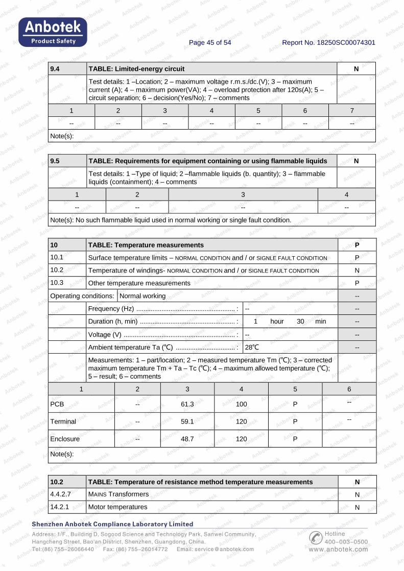
9.4 TABLE: Limited-energy circuit N
Test details: 1 –Location; 2 – maximum voltage r.m.s./dc.(V); 3 – maximum
current (A); 4 – maximum power(VA); 4 – overload protection after 120s(A); 5 –
circuit separation; 6 – decision(Yes/No); 7 – comments
1 2 3 4 5 6 7
-- -- -- -- -- -- --
Note(s):
9.5 TABLE: Requirements for equipment containing or using flammable liquids N
Test details: 1 –Type of liquid; 2 –flammable liquids (b. quantity); 3 – flammable
liquids (containment); 4 – comments
1 2 3 4
-- -- -- --
Note(s): No such flammable liquid used in normal working or single fault condition.
10 TABLE: Temperature measurements P
10.1 Surface temperature limits – NORMAL CONDITION and / or SIGNLE FAULT CONDITION P
10.2 Temperature of windings- NORMAL CONDITION and / or SIGNLE FAULT CONDITION N
10.3 Other temperature measurements P
Operating conditions: Normal working --
Frequency (Hz) ....................................................... : -- --
Duration (h, min) ..................................................... : 1 hour 30 min --
Voltage (V) .............................................................. : -- --
Ambient temperature Ta (℃) ................................. : 28℃ --
Measurements: 1 – part/location; 2 – measured temperature Tm (℃); 3 – corrected
maximum temperature Tm + Ta – Tc (℃); 4 – maximum allowed temperature (℃);
5 – result; 6 – comments
1 2 3 4 5 6
PCB -- 61.3 100 P --
Terminal -- 59.1 120 P --
Enclosure -- 48.7 120 P
Note(s):
10.2 TABLE: Temperature of resistance method temperature measurements N
4.4.2.7 MAINS Transformers N
14.2.1 Motor temperatures N
Page 46 of 54 Report No. 18250SC00074301
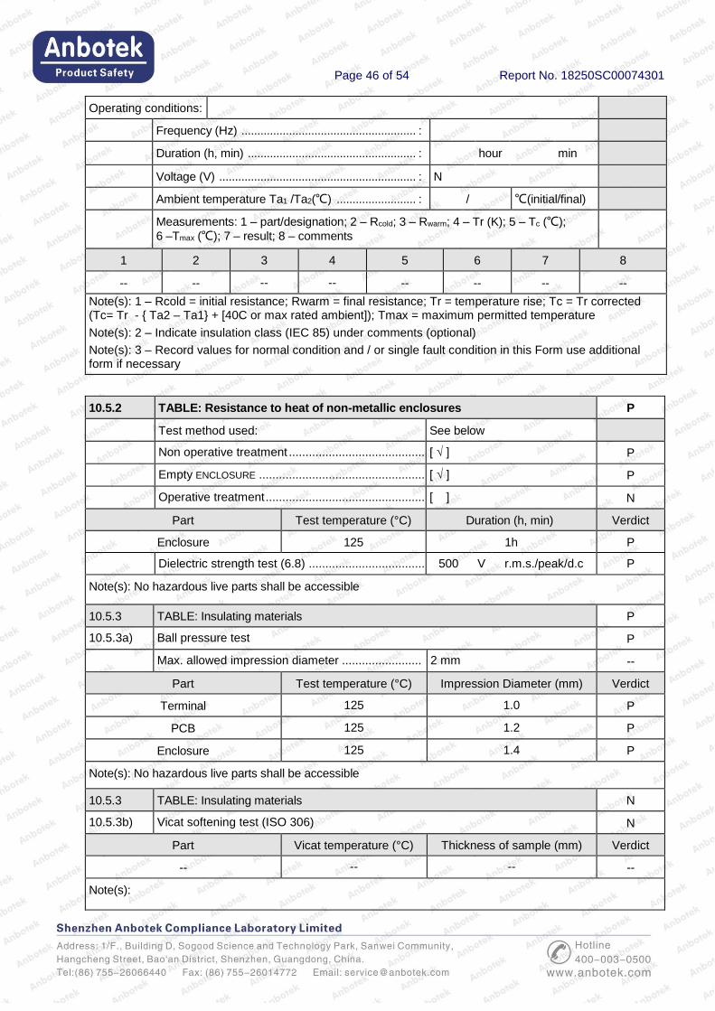
Operating conditions:
Frequency (Hz) ....................................................... :
Duration (h, min) ..................................................... : hour min
Voltage (V) .............................................................. : N
Ambient temperature Ta1 /Ta2(℃) ......................... : / ℃(initial/final)
Measurements: 1 – part/designation; 2 – Rcold; 3 – Rwarm; 4 – Tr (K); 5 – Tc (℃);
6 –Tmax (℃); 7 – result; 8 – comments
1 2 3 4 5 6 7 8
-- -- -- -- -- -- -- --
Note(s): 1 – Rcold = initial resistance; Rwarm = final resistance; Tr = temperature rise; Tc = Tr corrected (Tc= Tr - { Ta2 – Ta1} + [40C or max rated ambient]); Tmax = maximum permitted temperature
Note(s): 2 – Indicate insulation class (IEC 85) under comments (optional)
Note(s): 3 – Record values for normal condition and / or single fault condition in this Form use additional form if necessary
10.5.2 TABLE: Resistance to heat of non-metallic enclosures P
Test method used: See below
Non operative treatment ......................................... : [ √ ] P
Empty ENCLOSURE .................................................. : [ √ ] P
Operative treatment ................................................ : [ ] N
Part Test temperature (°C) Duration (h, min) Verdict
Enclosure 125 1h P
Dielectric strength test (6.8) ................................... : 500 V r.m.s./peak/d.c P
Note(s): No hazardous live parts shall be accessible
10.5.3 TABLE: Insulating materials P
10.5.3a) Ball pressure test P
Max. allowed impression diameter ........................ : 2 mm --
Part Test temperature (°C) Impression Diameter (mm) Verdict
Terminal 125 1.0 P
PCB 125 1.2 P
Enclosure 125 1.4 P
Note(s): No hazardous live parts shall be accessible
10.5.3 TABLE: Insulating materials N
10.5.3b) Vicat softening test (ISO 306) N
Part Vicat temperature (°C) Thickness of sample (mm) Verdict
-- -- -- --
Note(s):
Page 47 of 54 Report No. 18250SC00074301
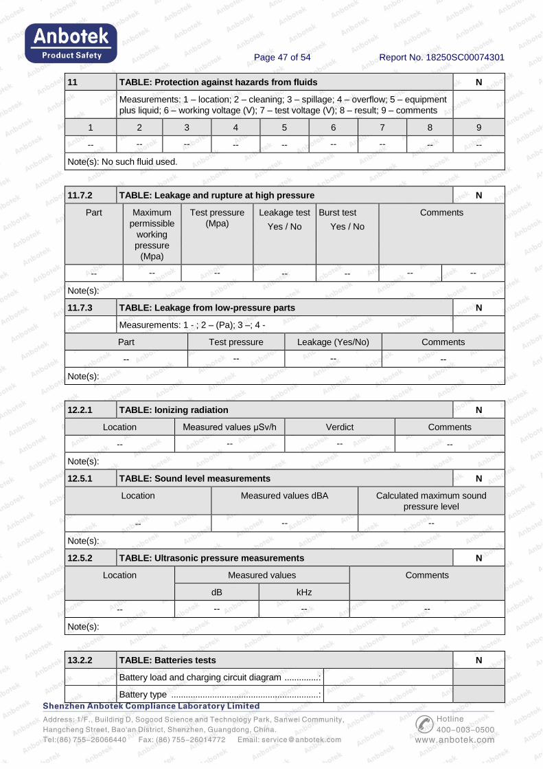
11 TABLE: Protection against hazards from fluids N
Measurements: 1 – location; 2 – cleaning; 3 – spillage; 4 – overflow; 5 – equipment
plus liquid; 6 – working voltage (V); 7 – test voltage (V); 8 – result; 9 – comments
1 2 3 4 5 6 7 8 9
-- -- -- -- -- -- -- -- --
Note(s): No such fluid used.
11.7.2 TABLE: Leakage and rupture at high pressure N
Part Maximum
permissible
working
pressure
(Mpa)
Test pressure
(Mpa)
Leakage test
Yes / No
Burst test
Yes / No
Comments
-- -- -- -- -- -- --
Note(s):
11.7.3 TABLE: Leakage from low-pressure parts N
Measurements: 1 - ; 2 – (Pa); 3 –; 4 -
Part Test pressure Leakage (Yes/No) Comments
-- -- -- --
Note(s):
12.2.1 TABLE: Ionizing radiation N
Location Measured values μSv/h Verdict Comments
-- -- -- --
Note(s):
12.5.1 TABLE: Sound level measurements N
Location Measured values dBA Calculated maximum sound
pressure level
-- -- --
Note(s):
12.5.2 TABLE: Ultrasonic pressure measurements N
Location Measured values Comments
dB kHz
-- -- -- --
Note(s):
13.2.2 TABLE: Batteries tests N
Battery load and charging circuit diagram .............. :
Battery type ............................................................. :
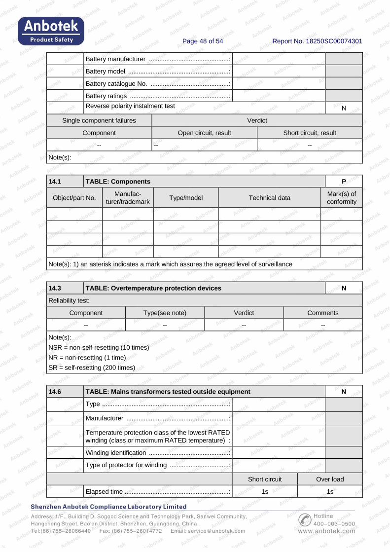
Page 48 of 54 Report No. 18250SC00074301
Battery manufacturer .............................................. :
Battery model .......................................................... :
Battery catalogue No. ............................................. :
Battery ratings ......................................................... :
Reverse polarity instalment test N
Single component failures Verdict
Component Open circuit, result Short circuit, result
-- -- --
Note(s):
14.1 TABLE: Components P
Object/part No. Manufac-
turer/trademark Type/model Technical data
Mark(s) of
conformity
Note(s): 1) an asterisk indicates a mark which assures the agreed level of surveillance
14.3 TABLE: Overtemperature protection devices N
Reliability test:
Component Type(see note) Verdict Comments
-- -- -- --
Note(s):
NSR = non-self-resetting (10 times)
NR = non-resetting (1 time)
SR = self-resetting (200 times)
14.6 TABLE: Mains transformers tested outside equipment N
Type ......................................................................... :
Manufacturer ........................................................... :
Temperature protection class of the lowest RATED
winding (class or maximum RATED temperature) :
Winding identification .............................................. :
Type of protector for winding .................................. :
Short circuit Over load
Elapsed time ............................................................ : 1s 1s

Page 49 of 54 Report No. 18250SC00074301
Current, primary (A) ................................................ : --- ---
Current, secondary (A) ............................................ : --- ---
Winding temperature, primary (℃) ......................... : --- ---
Winding temperature, secondary (℃) .................... : --- ---
Tissue paper/cheesecloth test ................................. : --- ---
Voltage test............................................................... : --- ---
Note(s): No any transformer used.

Page 50 of 54 Report No. 18250SC00074301
PHOTO DOCUMENTATION
Photo 1 [ ] front [ ] rear [ ] right side [ ] left side [√ ] top [ ] bottom [ ] internal
Photo 2 [√ ] front [ ] rear [ ] right side [ ] left side [ ] top [ ] bottom [ ] internal
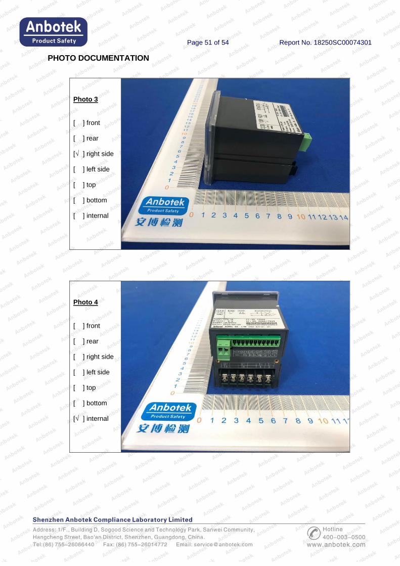
Page 51 of 54 Report No. 18250SC00074301
PHOTO DOCUMENTATION
Photo 3 [ ] front [ ] rear [√ ] right side [ ] left side [ ] top [ ] bottom [ ] internal
Photo 4 [ ] front [ ] rear [ ] right side [ ] left side [ ] top [ ] bottom [√ ] internal
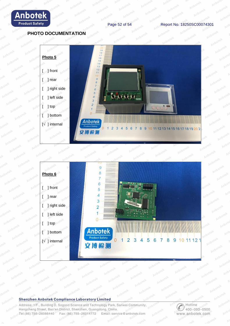
Page 52 of 54 Report No. 18250SC00074301
PHOTO DOCUMENTATION
Photo 5 [ ] front [ ] rear [ ] right side [ ] left side [ ] top [ ] bottom [√ ] internal
Photo 6 [ ] front [ ] rear [ ] right side [ ] left side [ ] top [ ] bottom [√ ] internal
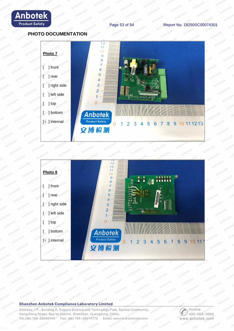
Page 53 of 54 Report No. 18250SC00074301
PHOTO DOCUMENTATION
Photo 7 [ ] front [ ] rear [ ] right side [ ] left side [ ] top [ ] bottom [√ ] internal
Photo 8 [ ] front [ ] rear [ ] right side [ ] left side [ ] top [ ] bottom [√ ] internal

Page 54 of 54 Report No. 18250SC00074301
PHOTO DOCUMENTATION
Photo 9 [ ] front [ ] rear [ ] right side [ ] left side [ ] top [ ] bottom [√ ] internal
Photo 10 [ ] front [ ] rear [ ] right side [ ] left side [ ] top [ ] bottom [√ ] internal
***End of report***