Embed Size (px)
Citation preview
ZiLOG Developer Studio II— ZNEO™
UM017103-0207
User Manual
ii
This publication is subject to replacement by a later edition. To determine whether a later edition exists, or to request copies of publications, visit www.zilog.com.
FeedbackFor any comments, detail technical questions, or reporting problems, please visit ZiLOG’s Technical Support at http://support.zilog.com.
Document Disclaimer©2007 by ZiLOG, Inc. All rights reserved. Information in this publication concerning the devices, applications, or technology described is intended to suggest possible uses and may be superseded. ZiLOG, INC. DOES NOT ASSUME LIABILITY FOR OR PROVIDE A REPRESENTATION OF ACCURACY OF THE INFORMATION, DEVICES, OR TECHNOLOGY DESCRIBED IN THIS DOCUMENT. ZiLOG ALSO DOES NOT ASSUME LIABILITY FOR INTELLECTUAL PROPERTY INFRINGEMENT RELATED IN ANY MANNER TO USE OF INFORMATION, DEVICES, OR TECHNOLOGY DESCRIBED HEREIN OR OTHERWISE. Devices sold by ZiLOG, Inc. are covered by warranty and limitation of liability provisions appearing in the ZiLOG, Inc. Terms and Conditions of Sale. ZiLOG, Inc. makes no warranty of merchantability or fitness for any purpose. Except with the express written approval of ZiLOG, use of information, devices, or technology as critical components of life support systems is not authorized. No licenses are conveyed, implicitly or otherwise, by this document under any intellectual property rights.Z8, Z8 Encore!, Z8 Encore! XP, Z8 Encore! MC, Crimzon, eZ80, and ZNEO are trademarks or registered trademarks of ZiLOG, Inc. All other products and/or service names mentioned herein may be trademarks of the companies with which they are associated.
UM017103-0207
ZiLOG Developer Studio IIZNEO™ User Manual
iii
Revision History
DateRevision Level Sections Description
January 2006
1 All Initial release
June 2006 2 “ZDS II System Requirements” on page xxiii
“FAQ.html file” on page xxv
“Developer’s Environment Tutorial” on page 1
Chapter 2, “Using the Integrated Development Environment”
“Warning and Error Messages” on page 152
“Label Field” on page 172
Chapter 6, “Configuring Memory for Your Program”
“Perform a Cyclic Redundancy Check” on page 286
“crc” on page 315
Updated.
Changed FAQ.txt to FAQ.html.
Updated screenshots.
Updated various sections, including the description of the memory map for CR 7124.
Added messages.
Updated.
Updated text and figures for CRs 7123 and 7124.
Added new section.
Added new section.
Revision History UM017103-0207
ZiLOG Developer Studio IIZNEO™ User Manual
iv
February 2007
3 Entire manual
Chapter 2, “Using the Integrated Development Environment”
Chapter 4, “Using the Macro Assembler”
Appendix B, “Using the Command Processor”
“ZDS II System Requirements” on page xxiii, “Create a New Project” on page 2, “New Project” on page 36, “Save Project” on page 41, “Find” on page 45, “Manage Breakpoints” on page 49, “Show Absolute Addresses in Assembly Listings” on page 80, “Fill Unused Hex File Bytes with 0xFF” on page 80, “Manage Configurations” on page 91, “Firmware Upgrade” on page 98, “Options—General Tab” on page 103, “Options—Editor Tab” on page 104, “Edit Menu Shortcuts” on page 110, “Preprocessor Warning and Error Messages” on page 152, “Label Field” on page 172, “Instruction” on page 173, “ORG” on page 188, “Using Breakpoints” on page 293, “Building a Project from the Command Line” on page 297, “Sample Command Script File” on page 311, “bp” on page 313, “cancel all” on page 314, “cancel bp” on page 314, and “Running the Flash Loader from the Command Processor” on page 333
“Select All” on page 45,“Show Whitespaces” on page 45, “Find Again” on page 46, “Clean” on page 89, “Structures and Unions in Assembly Code” on page 192, and “Anonymous Labels” on page 204
“Warning and Error Messages” on page 152 and “Warning and Error Messages” on page 248
“Edit Window” on page 27
Changed the description of the Project Settings dialog box.
Changed “Select Active Configuration” to “Select Build Configuration.” Changed File Verify button to Verify Download button.
Removed PL and PW for CR 3684.
Added Table 12 on page 308. Added the checksum, fillmem, loadmem, and savemem commands. Updated the sample command script file.
Updated.
Added new sections.
Added note for CR 5661.
Added new shortcuts.
DateRevision Level Sections Description
UM017103-0207 Revision History
ZiLOG Developer Studio IIZNEO™ User Manual
v
Table of ContentsPreface . . . . . . . . . . . . . . . . . . . . . . . . . . . . . . . . . . . . . . . . . . . . . . . . . . . . . . . . . . . . . . . . .xxiii
ZDS II System Requirements . . . . . . . . . . . . . . . . . . . . . . . . . . . . . . . . . . . . . . . . . . . .xxiiiSupported Operating Systems . . . . . . . . . . . . . . . . . . . . . . . . . . . . . . . . . . . . . . . . .xxiiiRecommended Host System Configuration . . . . . . . . . . . . . . . . . . . . . . . . . . . . . .xxiiiMinimum Host System Configuration . . . . . . . . . . . . . . . . . . . . . . . . . . . . . . . . . . xxivWhen Using the USB Smart Cable . . . . . . . . . . . . . . . . . . . . . . . . . . . . . . . . . . . . . xxivWhen Using the Ethernet Smart Cable . . . . . . . . . . . . . . . . . . . . . . . . . . . . . . . . . . xxiv
ZiLOG Technical Support . . . . . . . . . . . . . . . . . . . . . . . . . . . . . . . . . . . . . . . . . . . . . . . xxivBefore Contacting Technical Support . . . . . . . . . . . . . . . . . . . . . . . . . . . . . . . . . . . xxv
1 Getting Started . . . . . . . . . . . . . . . . . . . . . . . . . . . . . . . . . . . . . . . . . . . . . . . . . . . . . . . . . 1Installing ZDS II . . . . . . . . . . . . . . . . . . . . . . . . . . . . . . . . . . . . . . . . . . . . . . . . . . . . . . . . 1Developer’s Environment Tutorial . . . . . . . . . . . . . . . . . . . . . . . . . . . . . . . . . . . . . . . . . . 1
Create a New Project . . . . . . . . . . . . . . . . . . . . . . . . . . . . . . . . . . . . . . . . . . . . . . . . . 2Add a File to the Project . . . . . . . . . . . . . . . . . . . . . . . . . . . . . . . . . . . . . . . . . . . . . . . 6Set Up the Project . . . . . . . . . . . . . . . . . . . . . . . . . . . . . . . . . . . . . . . . . . . . . . . . . . . . 8Save the Project . . . . . . . . . . . . . . . . . . . . . . . . . . . . . . . . . . . . . . . . . . . . . . . . . . . . . 14
2 Using the Integrated Development Environment . . . . . . . . . . . . . . . . . . . . . . . . . . . . 15Toolbars . . . . . . . . . . . . . . . . . . . . . . . . . . . . . . . . . . . . . . . . . . . . . . . . . . . . . . . . . . . . . . 16
File Toolbar . . . . . . . . . . . . . . . . . . . . . . . . . . . . . . . . . . . . . . . . . . . . . . . . . . . . . . . . 17Build Toolbar . . . . . . . . . . . . . . . . . . . . . . . . . . . . . . . . . . . . . . . . . . . . . . . . . . . . . . 18Find Toolbar . . . . . . . . . . . . . . . . . . . . . . . . . . . . . . . . . . . . . . . . . . . . . . . . . . . . . . . 20Command Processor Toolbar . . . . . . . . . . . . . . . . . . . . . . . . . . . . . . . . . . . . . . . . . . 21Debug Toolbar . . . . . . . . . . . . . . . . . . . . . . . . . . . . . . . . . . . . . . . . . . . . . . . . . . . . . 22Debug Windows Toolbar . . . . . . . . . . . . . . . . . . . . . . . . . . . . . . . . . . . . . . . . . . . . . 24
Windows . . . . . . . . . . . . . . . . . . . . . . . . . . . . . . . . . . . . . . . . . . . . . . . . . . . . . . . . . . . . . 26Project Workspace Window . . . . . . . . . . . . . . . . . . . . . . . . . . . . . . . . . . . . . . . . . . . 26Edit Window . . . . . . . . . . . . . . . . . . . . . . . . . . . . . . . . . . . . . . . . . . . . . . . . . . . . . . . 27Output Windows . . . . . . . . . . . . . . . . . . . . . . . . . . . . . . . . . . . . . . . . . . . . . . . . . . . . 32
Menu Bar . . . . . . . . . . . . . . . . . . . . . . . . . . . . . . . . . . . . . . . . . . . . . . . . . . . . . . . . . . . . . 34File Menu . . . . . . . . . . . . . . . . . . . . . . . . . . . . . . . . . . . . . . . . . . . . . . . . . . . . . . . . . 35Edit Menu . . . . . . . . . . . . . . . . . . . . . . . . . . . . . . . . . . . . . . . . . . . . . . . . . . . . . . . . . 44View Menu . . . . . . . . . . . . . . . . . . . . . . . . . . . . . . . . . . . . . . . . . . . . . . . . . . . . . . . . 50Project Menu . . . . . . . . . . . . . . . . . . . . . . . . . . . . . . . . . . . . . . . . . . . . . . . . . . . . . . . 51Build Menu . . . . . . . . . . . . . . . . . . . . . . . . . . . . . . . . . . . . . . . . . . . . . . . . . . . . . . . . 89Debug Menu . . . . . . . . . . . . . . . . . . . . . . . . . . . . . . . . . . . . . . . . . . . . . . . . . . . . . . . 92Tools Menu . . . . . . . . . . . . . . . . . . . . . . . . . . . . . . . . . . . . . . . . . . . . . . . . . . . . . . . . 94Window Menu . . . . . . . . . . . . . . . . . . . . . . . . . . . . . . . . . . . . . . . . . . . . . . . . . . . . 108Help Menu . . . . . . . . . . . . . . . . . . . . . . . . . . . . . . . . . . . . . . . . . . . . . . . . . . . . . . . 109
Table of Contents UM017103-0207
ZiLOG Developer Studio IIZNEO™ User Manual
vi
Shortcut Keys . . . . . . . . . . . . . . . . . . . . . . . . . . . . . . . . . . . . . . . . . . . . . . . . . . . . . . . . 110File Menu Shortcuts . . . . . . . . . . . . . . . . . . . . . . . . . . . . . . . . . . . . . . . . . . . . . . . . 110Edit Menu Shortcuts . . . . . . . . . . . . . . . . . . . . . . . . . . . . . . . . . . . . . . . . . . . . . . . . 110Project Menu Shortcuts . . . . . . . . . . . . . . . . . . . . . . . . . . . . . . . . . . . . . . . . . . . . . . 111Build Menu Shortcuts . . . . . . . . . . . . . . . . . . . . . . . . . . . . . . . . . . . . . . . . . . . . . . . 111Debug Menu Shortcuts . . . . . . . . . . . . . . . . . . . . . . . . . . . . . . . . . . . . . . . . . . . . . . 112
3 Using the ANSI C-Compiler . . . . . . . . . . . . . . . . . . . . . . . . . . . . . . . . . . . . . . . . . . . . 113Language Extensions . . . . . . . . . . . . . . . . . . . . . . . . . . . . . . . . . . . . . . . . . . . . . . . . . . . 114
Additional Keywords for Storage Specification . . . . . . . . . . . . . . . . . . . . . . . . . . . 115Memory Models . . . . . . . . . . . . . . . . . . . . . . . . . . . . . . . . . . . . . . . . . . . . . . . . . . . 119Interrupt Support . . . . . . . . . . . . . . . . . . . . . . . . . . . . . . . . . . . . . . . . . . . . . . . . . . . 120Placement Directives . . . . . . . . . . . . . . . . . . . . . . . . . . . . . . . . . . . . . . . . . . . . . . . 121String Placement . . . . . . . . . . . . . . . . . . . . . . . . . . . . . . . . . . . . . . . . . . . . . . . . . . . 122Inline Assembly . . . . . . . . . . . . . . . . . . . . . . . . . . . . . . . . . . . . . . . . . . . . . . . . . . . 123Char and Short Enumerations . . . . . . . . . . . . . . . . . . . . . . . . . . . . . . . . . . . . . . . . . 124Setting Flash Option Bytes in C . . . . . . . . . . . . . . . . . . . . . . . . . . . . . . . . . . . . . . . 125Supported New Features from the 1999 Standard . . . . . . . . . . . . . . . . . . . . . . . . . 125
Type Sizes . . . . . . . . . . . . . . . . . . . . . . . . . . . . . . . . . . . . . . . . . . . . . . . . . . . . . . . . . . . 126Predefined Macros . . . . . . . . . . . . . . . . . . . . . . . . . . . . . . . . . . . . . . . . . . . . . . . . . . . . . 127
Examples . . . . . . . . . . . . . . . . . . . . . . . . . . . . . . . . . . . . . . . . . . . . . . . . . . . . . . . . . 128Calling Conventions . . . . . . . . . . . . . . . . . . . . . . . . . . . . . . . . . . . . . . . . . . . . . . . . . . . 128
Function Call Mechanism . . . . . . . . . . . . . . . . . . . . . . . . . . . . . . . . . . . . . . . . . . . . 128Special Cases . . . . . . . . . . . . . . . . . . . . . . . . . . . . . . . . . . . . . . . . . . . . . . . . . . . . . 130
Calling Assembly Functions from C . . . . . . . . . . . . . . . . . . . . . . . . . . . . . . . . . . . . . . . 131Function Naming Convention . . . . . . . . . . . . . . . . . . . . . . . . . . . . . . . . . . . . . . . . . 131Argument Locations . . . . . . . . . . . . . . . . . . . . . . . . . . . . . . . . . . . . . . . . . . . . . . . . 131Return Values . . . . . . . . . . . . . . . . . . . . . . . . . . . . . . . . . . . . . . . . . . . . . . . . . . . . . 132Preserving Registers . . . . . . . . . . . . . . . . . . . . . . . . . . . . . . . . . . . . . . . . . . . . . . . . 132
Calling C Functions from Assembly . . . . . . . . . . . . . . . . . . . . . . . . . . . . . . . . . . . . . . . 132Assembly File . . . . . . . . . . . . . . . . . . . . . . . . . . . . . . . . . . . . . . . . . . . . . . . . . . . . . 132Referenced C Function Prototype . . . . . . . . . . . . . . . . . . . . . . . . . . . . . . . . . . . . . . 133
Command Line Options . . . . . . . . . . . . . . . . . . . . . . . . . . . . . . . . . . . . . . . . . . . . . . . . 133Run-Time Library . . . . . . . . . . . . . . . . . . . . . . . . . . . . . . . . . . . . . . . . . . . . . . . . . . . . . 133
ZiLOG Header Files . . . . . . . . . . . . . . . . . . . . . . . . . . . . . . . . . . . . . . . . . . . . . . . . 134ZiLOG Functions . . . . . . . . . . . . . . . . . . . . . . . . . . . . . . . . . . . . . . . . . . . . . . . . . . 136
Stack Pointer Overflow . . . . . . . . . . . . . . . . . . . . . . . . . . . . . . . . . . . . . . . . . . . . . . . . . 142Startup Files . . . . . . . . . . . . . . . . . . . . . . . . . . . . . . . . . . . . . . . . . . . . . . . . . . . . . . . . . . 142Segment Naming . . . . . . . . . . . . . . . . . . . . . . . . . . . . . . . . . . . . . . . . . . . . . . . . . . . . . . 143Linker Command Files for C Programs . . . . . . . . . . . . . . . . . . . . . . . . . . . . . . . . . . . . 144
Linker Referenced Files . . . . . . . . . . . . . . . . . . . . . . . . . . . . . . . . . . . . . . . . . . . . . 146Linker Symbols . . . . . . . . . . . . . . . . . . . . . . . . . . . . . . . . . . . . . . . . . . . . . . . . . . . . 147
UM017103-0207 Table of Contents
ZiLOG Developer Studio IIZNEO™ User Manual
vii
Sample Linker Command File . . . . . . . . . . . . . . . . . . . . . . . . . . . . . . . . . . . . . . . . 147ANSI Standard Compliance . . . . . . . . . . . . . . . . . . . . . . . . . . . . . . . . . . . . . . . . . . . . . 150
Freestanding Implementation . . . . . . . . . . . . . . . . . . . . . . . . . . . . . . . . . . . . . . . . . 150Deviations from ANSI C . . . . . . . . . . . . . . . . . . . . . . . . . . . . . . . . . . . . . . . . . . . . 150
Warning and Error Messages . . . . . . . . . . . . . . . . . . . . . . . . . . . . . . . . . . . . . . . . . . . . 152Preprocessor Warning and Error Messages . . . . . . . . . . . . . . . . . . . . . . . . . . . . . . 152Front-End Warning and Error Messages . . . . . . . . . . . . . . . . . . . . . . . . . . . . . . . . 155Optimizer Warning and Error Messages . . . . . . . . . . . . . . . . . . . . . . . . . . . . . . . . . 164Code Generator Warning and Error Messages . . . . . . . . . . . . . . . . . . . . . . . . . . . . 166
4 Using the Macro Assembler. . . . . . . . . . . . . . . . . . . . . . . . . . . . . . . . . . . . . . . . . . . . . 167Address Spaces and Segments . . . . . . . . . . . . . . . . . . . . . . . . . . . . . . . . . . . . . . . . . . . . 167
Allocating Processor Memory . . . . . . . . . . . . . . . . . . . . . . . . . . . . . . . . . . . . . . . . 168Address Spaces . . . . . . . . . . . . . . . . . . . . . . . . . . . . . . . . . . . . . . . . . . . . . . . . . . . . 168Segments . . . . . . . . . . . . . . . . . . . . . . . . . . . . . . . . . . . . . . . . . . . . . . . . . . . . . . . . . 168Assigning Memory at Link Time . . . . . . . . . . . . . . . . . . . . . . . . . . . . . . . . . . . . . . 170
Output Files . . . . . . . . . . . . . . . . . . . . . . . . . . . . . . . . . . . . . . . . . . . . . . . . . . . . . . . . . . 170Source Listing (.lst) Format . . . . . . . . . . . . . . . . . . . . . . . . . . . . . . . . . . . . . . . . . . 170Object Code (.obj) File . . . . . . . . . . . . . . . . . . . . . . . . . . . . . . . . . . . . . . . . . . . . . . 171
Source Language Structure . . . . . . . . . . . . . . . . . . . . . . . . . . . . . . . . . . . . . . . . . . . . . . 172General Structure . . . . . . . . . . . . . . . . . . . . . . . . . . . . . . . . . . . . . . . . . . . . . . . . . . 172Assembler Rules . . . . . . . . . . . . . . . . . . . . . . . . . . . . . . . . . . . . . . . . . . . . . . . . . . . 173
Expressions . . . . . . . . . . . . . . . . . . . . . . . . . . . . . . . . . . . . . . . . . . . . . . . . . . . . . . . . . . 175Arithmetic Operators . . . . . . . . . . . . . . . . . . . . . . . . . . . . . . . . . . . . . . . . . . . . . . . 176Relational Operators . . . . . . . . . . . . . . . . . . . . . . . . . . . . . . . . . . . . . . . . . . . . . . . . 176Boolean Operators . . . . . . . . . . . . . . . . . . . . . . . . . . . . . . . . . . . . . . . . . . . . . . . . . 176LOW and LOW16 Operators . . . . . . . . . . . . . . . . . . . . . . . . . . . . . . . . . . . . . . . . . 176Decimal Numbers . . . . . . . . . . . . . . . . . . . . . . . . . . . . . . . . . . . . . . . . . . . . . . . . . . 177Hexadecimal Numbers . . . . . . . . . . . . . . . . . . . . . . . . . . . . . . . . . . . . . . . . . . . . . . 177Binary Numbers . . . . . . . . . . . . . . . . . . . . . . . . . . . . . . . . . . . . . . . . . . . . . . . . . . . 177Octal Numbers . . . . . . . . . . . . . . . . . . . . . . . . . . . . . . . . . . . . . . . . . . . . . . . . . . . . 177Character Constants . . . . . . . . . . . . . . . . . . . . . . . . . . . . . . . . . . . . . . . . . . . . . . . . 178Operator Precedence . . . . . . . . . . . . . . . . . . . . . . . . . . . . . . . . . . . . . . . . . . . . . . . . 178Address Spaces and Instruction Encoding . . . . . . . . . . . . . . . . . . . . . . . . . . . . . . . 179
Directives . . . . . . . . . . . . . . . . . . . . . . . . . . . . . . . . . . . . . . . . . . . . . . . . . . . . . . . . . . . . 181ALIGN . . . . . . . . . . . . . . . . . . . . . . . . . . . . . . . . . . . . . . . . . . . . . . . . . . . . . . . . . . 181.COMMENT . . . . . . . . . . . . . . . . . . . . . . . . . . . . . . . . . . . . . . . . . . . . . . . . . . . . . . 182CPU . . . . . . . . . . . . . . . . . . . . . . . . . . . . . . . . . . . . . . . . . . . . . . . . . . . . . . . . . . . . . 182Data Directives . . . . . . . . . . . . . . . . . . . . . . . . . . . . . . . . . . . . . . . . . . . . . . . . . . . . 182DEFINE . . . . . . . . . . . . . . . . . . . . . . . . . . . . . . . . . . . . . . . . . . . . . . . . . . . . . . . . . 185DS . . . . . . . . . . . . . . . . . . . . . . . . . . . . . . . . . . . . . . . . . . . . . . . . . . . . . . . . . . . . . . 186END . . . . . . . . . . . . . . . . . . . . . . . . . . . . . . . . . . . . . . . . . . . . . . . . . . . . . . . . . . . . 186
Table of Contents UM017103-0207
ZiLOG Developer Studio IIZNEO™ User Manual
viii
EQU . . . . . . . . . . . . . . . . . . . . . . . . . . . . . . . . . . . . . . . . . . . . . . . . . . . . . . . . . . . . 187INCLUDE . . . . . . . . . . . . . . . . . . . . . . . . . . . . . . . . . . . . . . . . . . . . . . . . . . . . . . . . 187LIST . . . . . . . . . . . . . . . . . . . . . . . . . . . . . . . . . . . . . . . . . . . . . . . . . . . . . . . . . . . . 188NOLIST . . . . . . . . . . . . . . . . . . . . . . . . . . . . . . . . . . . . . . . . . . . . . . . . . . . . . . . . . 188ORG . . . . . . . . . . . . . . . . . . . . . . . . . . . . . . . . . . . . . . . . . . . . . . . . . . . . . . . . . . . . 188SEGMENT . . . . . . . . . . . . . . . . . . . . . . . . . . . . . . . . . . . . . . . . . . . . . . . . . . . . . . . 189.SHORT_STACK_FRAME . . . . . . . . . . . . . . . . . . . . . . . . . . . . . . . . . . . . . . . . . . 189TITLE . . . . . . . . . . . . . . . . . . . . . . . . . . . . . . . . . . . . . . . . . . . . . . . . . . . . . . . . . . . 190VAR . . . . . . . . . . . . . . . . . . . . . . . . . . . . . . . . . . . . . . . . . . . . . . . . . . . . . . . . . . . . 190VECTOR . . . . . . . . . . . . . . . . . . . . . . . . . . . . . . . . . . . . . . . . . . . . . . . . . . . . . . . . . 191XDEF . . . . . . . . . . . . . . . . . . . . . . . . . . . . . . . . . . . . . . . . . . . . . . . . . . . . . . . . . . . 192XREF . . . . . . . . . . . . . . . . . . . . . . . . . . . . . . . . . . . . . . . . . . . . . . . . . . . . . . . . . . . 192Structures and Unions in Assembly Code . . . . . . . . . . . . . . . . . . . . . . . . . . . . . . . 192
Conditional Assembly . . . . . . . . . . . . . . . . . . . . . . . . . . . . . . . . . . . . . . . . . . . . . . . . . . 197Conditional Assembly Directives . . . . . . . . . . . . . . . . . . . . . . . . . . . . . . . . . . . . . . 198
Macros . . . . . . . . . . . . . . . . . . . . . . . . . . . . . . . . . . . . . . . . . . . . . . . . . . . . . . . . . . . . . . 200Macro Definition . . . . . . . . . . . . . . . . . . . . . . . . . . . . . . . . . . . . . . . . . . . . . . . . . . . 200Concatenation . . . . . . . . . . . . . . . . . . . . . . . . . . . . . . . . . . . . . . . . . . . . . . . . . . . . . 201Macro Invocation . . . . . . . . . . . . . . . . . . . . . . . . . . . . . . . . . . . . . . . . . . . . . . . . . . 201Local Macro Labels . . . . . . . . . . . . . . . . . . . . . . . . . . . . . . . . . . . . . . . . . . . . . . . . 202Optional Macro Arguments . . . . . . . . . . . . . . . . . . . . . . . . . . . . . . . . . . . . . . . . . . 202Exiting a Macro . . . . . . . . . . . . . . . . . . . . . . . . . . . . . . . . . . . . . . . . . . . . . . . . . . . . 203
Labels . . . . . . . . . . . . . . . . . . . . . . . . . . . . . . . . . . . . . . . . . . . . . . . . . . . . . . . . . . . . . . 203Anonymous Labels . . . . . . . . . . . . . . . . . . . . . . . . . . . . . . . . . . . . . . . . . . . . . . . . . 204Local Labels . . . . . . . . . . . . . . . . . . . . . . . . . . . . . . . . . . . . . . . . . . . . . . . . . . . . . . 204Importing and Exporting Labels . . . . . . . . . . . . . . . . . . . . . . . . . . . . . . . . . . . . . . . 204Label Spaces . . . . . . . . . . . . . . . . . . . . . . . . . . . . . . . . . . . . . . . . . . . . . . . . . . . . . . 204
Source Language Syntax . . . . . . . . . . . . . . . . . . . . . . . . . . . . . . . . . . . . . . . . . . . . . . . . 205Warning and Error Messages . . . . . . . . . . . . . . . . . . . . . . . . . . . . . . . . . . . . . . . . . . . . 208
5 Using the Linker/Locator. . . . . . . . . . . . . . . . . . . . . . . . . . . . . . . . . . . . . . . . . . . . . . . 213Linker Functions . . . . . . . . . . . . . . . . . . . . . . . . . . . . . . . . . . . . . . . . . . . . . . . . . . . . . . 213Invoking the Linker . . . . . . . . . . . . . . . . . . . . . . . . . . . . . . . . . . . . . . . . . . . . . . . . . . . . 214Linker Commands . . . . . . . . . . . . . . . . . . . . . . . . . . . . . . . . . . . . . . . . . . . . . . . . . . . . . 215
<outputfile>=<module list> . . . . . . . . . . . . . . . . . . . . . . . . . . . . . . . . . . . . . . . . . . 216CHANGE . . . . . . . . . . . . . . . . . . . . . . . . . . . . . . . . . . . . . . . . . . . . . . . . . . . . . . . . 216COPY . . . . . . . . . . . . . . . . . . . . . . . . . . . . . . . . . . . . . . . . . . . . . . . . . . . . . . . . . . . 217DEBUG . . . . . . . . . . . . . . . . . . . . . . . . . . . . . . . . . . . . . . . . . . . . . . . . . . . . . . . . . . 218DEFINE . . . . . . . . . . . . . . . . . . . . . . . . . . . . . . . . . . . . . . . . . . . . . . . . . . . . . . . . . 218FORMAT . . . . . . . . . . . . . . . . . . . . . . . . . . . . . . . . . . . . . . . . . . . . . . . . . . . . . . . . 219GROUP . . . . . . . . . . . . . . . . . . . . . . . . . . . . . . . . . . . . . . . . . . . . . . . . . . . . . . . . . . 219HEADING . . . . . . . . . . . . . . . . . . . . . . . . . . . . . . . . . . . . . . . . . . . . . . . . . . . . . . . 219
UM017103-0207 Table of Contents
ZiLOG Developer Studio IIZNEO™ User Manual
ix
LOCATE . . . . . . . . . . . . . . . . . . . . . . . . . . . . . . . . . . . . . . . . . . . . . . . . . . . . . . . . . 220MAP . . . . . . . . . . . . . . . . . . . . . . . . . . . . . . . . . . . . . . . . . . . . . . . . . . . . . . . . . . . . 220MAXHEXLEN . . . . . . . . . . . . . . . . . . . . . . . . . . . . . . . . . . . . . . . . . . . . . . . . . . . . 220MAXLENGTH . . . . . . . . . . . . . . . . . . . . . . . . . . . . . . . . . . . . . . . . . . . . . . . . . . . . 221NODEBUG . . . . . . . . . . . . . . . . . . . . . . . . . . . . . . . . . . . . . . . . . . . . . . . . . . . . . . . 221NOMAP . . . . . . . . . . . . . . . . . . . . . . . . . . . . . . . . . . . . . . . . . . . . . . . . . . . . . . . . . 221NOWARN . . . . . . . . . . . . . . . . . . . . . . . . . . . . . . . . . . . . . . . . . . . . . . . . . . . . . . . . 222ORDER . . . . . . . . . . . . . . . . . . . . . . . . . . . . . . . . . . . . . . . . . . . . . . . . . . . . . . . . . . 222RANGE . . . . . . . . . . . . . . . . . . . . . . . . . . . . . . . . . . . . . . . . . . . . . . . . . . . . . . . . . . 222SEARCHPATH . . . . . . . . . . . . . . . . . . . . . . . . . . . . . . . . . . . . . . . . . . . . . . . . . . . 223SEQUENCE . . . . . . . . . . . . . . . . . . . . . . . . . . . . . . . . . . . . . . . . . . . . . . . . . . . . . . 223SORT . . . . . . . . . . . . . . . . . . . . . . . . . . . . . . . . . . . . . . . . . . . . . . . . . . . . . . . . . . . 223SPLITTABLE . . . . . . . . . . . . . . . . . . . . . . . . . . . . . . . . . . . . . . . . . . . . . . . . . . . . . 224UNRESOLVED IS FATAL . . . . . . . . . . . . . . . . . . . . . . . . . . . . . . . . . . . . . . . . . . 224WARN . . . . . . . . . . . . . . . . . . . . . . . . . . . . . . . . . . . . . . . . . . . . . . . . . . . . . . . . . . 225WARNING IS FATAL . . . . . . . . . . . . . . . . . . . . . . . . . . . . . . . . . . . . . . . . . . . . . . 225WARNOVERLAP . . . . . . . . . . . . . . . . . . . . . . . . . . . . . . . . . . . . . . . . . . . . . . . . . 225
Linker Expressions . . . . . . . . . . . . . . . . . . . . . . . . . . . . . . . . . . . . . . . . . . . . . . . . . . . . 226Examples . . . . . . . . . . . . . . . . . . . . . . . . . . . . . . . . . . . . . . . . . . . . . . . . . . . . . . . . . 227+ (Add) . . . . . . . . . . . . . . . . . . . . . . . . . . . . . . . . . . . . . . . . . . . . . . . . . . . . . . . . . . 227& (And) . . . . . . . . . . . . . . . . . . . . . . . . . . . . . . . . . . . . . . . . . . . . . . . . . . . . . . . . . . 227BASE OF . . . . . . . . . . . . . . . . . . . . . . . . . . . . . . . . . . . . . . . . . . . . . . . . . . . . . . . . 227COPY BASE . . . . . . . . . . . . . . . . . . . . . . . . . . . . . . . . . . . . . . . . . . . . . . . . . . . . . . 228COPY TOP . . . . . . . . . . . . . . . . . . . . . . . . . . . . . . . . . . . . . . . . . . . . . . . . . . . . . . . 228/ (Divide) . . . . . . . . . . . . . . . . . . . . . . . . . . . . . . . . . . . . . . . . . . . . . . . . . . . . . . . . . 228FREEMEM . . . . . . . . . . . . . . . . . . . . . . . . . . . . . . . . . . . . . . . . . . . . . . . . . . . . . . . 229HIGHADDR . . . . . . . . . . . . . . . . . . . . . . . . . . . . . . . . . . . . . . . . . . . . . . . . . . . . . . 229LENGTH . . . . . . . . . . . . . . . . . . . . . . . . . . . . . . . . . . . . . . . . . . . . . . . . . . . . . . . . . 229LOWADDR . . . . . . . . . . . . . . . . . . . . . . . . . . . . . . . . . . . . . . . . . . . . . . . . . . . . . . 229* (Multiply) . . . . . . . . . . . . . . . . . . . . . . . . . . . . . . . . . . . . . . . . . . . . . . . . . . . . . . . 230Decimal Numeric Values . . . . . . . . . . . . . . . . . . . . . . . . . . . . . . . . . . . . . . . . . . . . 230Hexadecimal Numeric Values . . . . . . . . . . . . . . . . . . . . . . . . . . . . . . . . . . . . . . . . 231| (Or) . . . . . . . . . . . . . . . . . . . . . . . . . . . . . . . . . . . . . . . . . . . . . . . . . . . . . . . . . . . . 231<< (Shift Left) . . . . . . . . . . . . . . . . . . . . . . . . . . . . . . . . . . . . . . . . . . . . . . . . . . . . . 231>> (Shift Right) . . . . . . . . . . . . . . . . . . . . . . . . . . . . . . . . . . . . . . . . . . . . . . . . . . . . 231- (Subtract) . . . . . . . . . . . . . . . . . . . . . . . . . . . . . . . . . . . . . . . . . . . . . . . . . . . . . . . 231TOP OF . . . . . . . . . . . . . . . . . . . . . . . . . . . . . . . . . . . . . . . . . . . . . . . . . . . . . . . . . . 231^ (Bitwise Exclusive Or) . . . . . . . . . . . . . . . . . . . . . . . . . . . . . . . . . . . . . . . . . . . . . 232~ (Not) . . . . . . . . . . . . . . . . . . . . . . . . . . . . . . . . . . . . . . . . . . . . . . . . . . . . . . . . . . . 232
Sample Linker Map File . . . . . . . . . . . . . . . . . . . . . . . . . . . . . . . . . . . . . . . . . . . . . . . . 232Troubleshooting the Linker . . . . . . . . . . . . . . . . . . . . . . . . . . . . . . . . . . . . . . . . . . . . . . 246
Table of Contents UM017103-0207
ZiLOG Developer Studio IIZNEO™ User Manual
x
How do I speed up the linker? . . . . . . . . . . . . . . . . . . . . . . . . . . . . . . . . . . . . . . . . 247How do I generate debug information without generating code? . . . . . . . . . . . . . . 247How much memory is my program using? . . . . . . . . . . . . . . . . . . . . . . . . . . . . . . . 247How do I create a hex file? . . . . . . . . . . . . . . . . . . . . . . . . . . . . . . . . . . . . . . . . . . . 247How do I determine the size of my actual hex code? . . . . . . . . . . . . . . . . . . . . . . . 247
Warning and Error Messages . . . . . . . . . . . . . . . . . . . . . . . . . . . . . . . . . . . . . . . . . . . . 2486 Configuring Memory for Your Program . . . . . . . . . . . . . . . . . . . . . . . . . . . . . . . . . . 251
ZNEO Memory Layout . . . . . . . . . . . . . . . . . . . . . . . . . . . . . . . . . . . . . . . . . . . . . . . . . 251Programmer’s Model of ZNEO Memory . . . . . . . . . . . . . . . . . . . . . . . . . . . . . . . . . . . 253
Unconventional Memory Layouts . . . . . . . . . . . . . . . . . . . . . . . . . . . . . . . . . . . . . 257Program Configurations . . . . . . . . . . . . . . . . . . . . . . . . . . . . . . . . . . . . . . . . . . . . . . . . 258
Default Program Configuration . . . . . . . . . . . . . . . . . . . . . . . . . . . . . . . . . . . . . . . 258Download to ERAM Program Configuration . . . . . . . . . . . . . . . . . . . . . . . . . . . . . 262Download to RAM Program Configuration . . . . . . . . . . . . . . . . . . . . . . . . . . . . . . 265Copy to ERAM Program Configuration . . . . . . . . . . . . . . . . . . . . . . . . . . . . . . . . . 268Copy to RAM Program Configuration . . . . . . . . . . . . . . . . . . . . . . . . . . . . . . . . . . 272
7 Using the Debugger . . . . . . . . . . . . . . . . . . . . . . . . . . . . . . . . . . . . . . . . . . . . . . . . . . . 277Status Bar . . . . . . . . . . . . . . . . . . . . . . . . . . . . . . . . . . . . . . . . . . . . . . . . . . . . . . . . . . . . 278Code Line Indicators . . . . . . . . . . . . . . . . . . . . . . . . . . . . . . . . . . . . . . . . . . . . . . . . . . . 279Debug Windows . . . . . . . . . . . . . . . . . . . . . . . . . . . . . . . . . . . . . . . . . . . . . . . . . . . . . . 279
Registers Window . . . . . . . . . . . . . . . . . . . . . . . . . . . . . . . . . . . . . . . . . . . . . . . . . . 279Special Function Registers Window . . . . . . . . . . . . . . . . . . . . . . . . . . . . . . . . . . . . 280Clock Window . . . . . . . . . . . . . . . . . . . . . . . . . . . . . . . . . . . . . . . . . . . . . . . . . . . . 281Memory Window . . . . . . . . . . . . . . . . . . . . . . . . . . . . . . . . . . . . . . . . . . . . . . . . . . 282Watch Window . . . . . . . . . . . . . . . . . . . . . . . . . . . . . . . . . . . . . . . . . . . . . . . . . . . . 287Locals Window . . . . . . . . . . . . . . . . . . . . . . . . . . . . . . . . . . . . . . . . . . . . . . . . . . . . 290Call Stack Window . . . . . . . . . . . . . . . . . . . . . . . . . . . . . . . . . . . . . . . . . . . . . . . . . 290Symbols Window . . . . . . . . . . . . . . . . . . . . . . . . . . . . . . . . . . . . . . . . . . . . . . . . . . 291Disassembly Window . . . . . . . . . . . . . . . . . . . . . . . . . . . . . . . . . . . . . . . . . . . . . . . 291Simulated UART Output Window . . . . . . . . . . . . . . . . . . . . . . . . . . . . . . . . . . . . . 292
Using Breakpoints . . . . . . . . . . . . . . . . . . . . . . . . . . . . . . . . . . . . . . . . . . . . . . . . . . . . . 293Inserting Breakpoints . . . . . . . . . . . . . . . . . . . . . . . . . . . . . . . . . . . . . . . . . . . . . . . 293Viewing Breakpoints . . . . . . . . . . . . . . . . . . . . . . . . . . . . . . . . . . . . . . . . . . . . . . . 294Moving to a Breakpoint . . . . . . . . . . . . . . . . . . . . . . . . . . . . . . . . . . . . . . . . . . . . . 295Enabling Breakpoints . . . . . . . . . . . . . . . . . . . . . . . . . . . . . . . . . . . . . . . . . . . . . . . 295Disabling Breakpoints . . . . . . . . . . . . . . . . . . . . . . . . . . . . . . . . . . . . . . . . . . . . . . . 295Removing Breakpoints . . . . . . . . . . . . . . . . . . . . . . . . . . . . . . . . . . . . . . . . . . . . . . 296
Appendix ARunning ZDS II from the Command Line. . . . . . . . . . . . . . . . . . . . . . . . . . 297Building a Project from the Command Line . . . . . . . . . . . . . . . . . . . . . . . . . . . . . . . . . 297Running the Compiler from the Command Line . . . . . . . . . . . . . . . . . . . . . . . . . . . . . . 298Running the Assembler from the Command Line . . . . . . . . . . . . . . . . . . . . . . . . . . . . . 298
UM017103-0207 Table of Contents
ZiLOG Developer Studio IIZNEO™ User Manual
xi
Running the Linker from the Command Line . . . . . . . . . . . . . . . . . . . . . . . . . . . . . . . . 298Assembler Command Line Options . . . . . . . . . . . . . . . . . . . . . . . . . . . . . . . . . . . . . . . 299Compiler Command Line Options . . . . . . . . . . . . . . . . . . . . . . . . . . . . . . . . . . . . . . . . 301Librarian Command Line Options . . . . . . . . . . . . . . . . . . . . . . . . . . . . . . . . . . . . . . . . . 304Linker Command Line Options . . . . . . . . . . . . . . . . . . . . . . . . . . . . . . . . . . . . . . . . . . . 304
Appendix BUsing the Command Processor . . . . . . . . . . . . . . . . . . . . . . . . . . . . . . . . . . . 307Sample Command Script File . . . . . . . . . . . . . . . . . . . . . . . . . . . . . . . . . . . . . . . . . . . . 311Supported Script File Commands . . . . . . . . . . . . . . . . . . . . . . . . . . . . . . . . . . . . . . . . . 312
add file . . . . . . . . . . . . . . . . . . . . . . . . . . . . . . . . . . . . . . . . . . . . . . . . . . . . . . . . . . 312batch . . . . . . . . . . . . . . . . . . . . . . . . . . . . . . . . . . . . . . . . . . . . . . . . . . . . . . . . . . . . 312bp . . . . . . . . . . . . . . . . . . . . . . . . . . . . . . . . . . . . . . . . . . . . . . . . . . . . . . . . . . . . . . . 313build . . . . . . . . . . . . . . . . . . . . . . . . . . . . . . . . . . . . . . . . . . . . . . . . . . . . . . . . . . . . 314cancel all . . . . . . . . . . . . . . . . . . . . . . . . . . . . . . . . . . . . . . . . . . . . . . . . . . . . . . . . . 314cancel bp . . . . . . . . . . . . . . . . . . . . . . . . . . . . . . . . . . . . . . . . . . . . . . . . . . . . . . . . . 314cd . . . . . . . . . . . . . . . . . . . . . . . . . . . . . . . . . . . . . . . . . . . . . . . . . . . . . . . . . . . . . . . 314checksum . . . . . . . . . . . . . . . . . . . . . . . . . . . . . . . . . . . . . . . . . . . . . . . . . . . . . . . . . 315crc . . . . . . . . . . . . . . . . . . . . . . . . . . . . . . . . . . . . . . . . . . . . . . . . . . . . . . . . . . . . . . 315debugtool copy . . . . . . . . . . . . . . . . . . . . . . . . . . . . . . . . . . . . . . . . . . . . . . . . . . . . 315debugtool create . . . . . . . . . . . . . . . . . . . . . . . . . . . . . . . . . . . . . . . . . . . . . . . . . . . 316debugtool get . . . . . . . . . . . . . . . . . . . . . . . . . . . . . . . . . . . . . . . . . . . . . . . . . . . . . . 316debugtool help . . . . . . . . . . . . . . . . . . . . . . . . . . . . . . . . . . . . . . . . . . . . . . . . . . . . . 316debugtool list . . . . . . . . . . . . . . . . . . . . . . . . . . . . . . . . . . . . . . . . . . . . . . . . . . . . . . 316debugtool save . . . . . . . . . . . . . . . . . . . . . . . . . . . . . . . . . . . . . . . . . . . . . . . . . . . . 316debugtool set . . . . . . . . . . . . . . . . . . . . . . . . . . . . . . . . . . . . . . . . . . . . . . . . . . . . . . 317debugtool setup . . . . . . . . . . . . . . . . . . . . . . . . . . . . . . . . . . . . . . . . . . . . . . . . . . . . 317defines . . . . . . . . . . . . . . . . . . . . . . . . . . . . . . . . . . . . . . . . . . . . . . . . . . . . . . . . . . . 317delete config . . . . . . . . . . . . . . . . . . . . . . . . . . . . . . . . . . . . . . . . . . . . . . . . . . . . . . 318examine (?) for Expressions . . . . . . . . . . . . . . . . . . . . . . . . . . . . . . . . . . . . . . . . . . 318examine (?) for Variables . . . . . . . . . . . . . . . . . . . . . . . . . . . . . . . . . . . . . . . . . . . . 319exit . . . . . . . . . . . . . . . . . . . . . . . . . . . . . . . . . . . . . . . . . . . . . . . . . . . . . . . . . . . . . . 320fillmem . . . . . . . . . . . . . . . . . . . . . . . . . . . . . . . . . . . . . . . . . . . . . . . . . . . . . . . . . . 320go . . . . . . . . . . . . . . . . . . . . . . . . . . . . . . . . . . . . . . . . . . . . . . . . . . . . . . . . . . . . . . . 320list bp . . . . . . . . . . . . . . . . . . . . . . . . . . . . . . . . . . . . . . . . . . . . . . . . . . . . . . . . . . . . 320loadmem . . . . . . . . . . . . . . . . . . . . . . . . . . . . . . . . . . . . . . . . . . . . . . . . . . . . . . . . . 320log . . . . . . . . . . . . . . . . . . . . . . . . . . . . . . . . . . . . . . . . . . . . . . . . . . . . . . . . . . . . . . 321makfile or makefile . . . . . . . . . . . . . . . . . . . . . . . . . . . . . . . . . . . . . . . . . . . . . . . . . 321new project . . . . . . . . . . . . . . . . . . . . . . . . . . . . . . . . . . . . . . . . . . . . . . . . . . . . . . . 322open project . . . . . . . . . . . . . . . . . . . . . . . . . . . . . . . . . . . . . . . . . . . . . . . . . . . . . . . 322option . . . . . . . . . . . . . . . . . . . . . . . . . . . . . . . . . . . . . . . . . . . . . . . . . . . . . . . . . . . 323print . . . . . . . . . . . . . . . . . . . . . . . . . . . . . . . . . . . . . . . . . . . . . . . . . . . . . . . . . . . . . 327pwd . . . . . . . . . . . . . . . . . . . . . . . . . . . . . . . . . . . . . . . . . . . . . . . . . . . . . . . . . . . . . 327
Table of Contents UM017103-0207
ZiLOG Developer Studio IIZNEO™ User Manual
xii
quit . . . . . . . . . . . . . . . . . . . . . . . . . . . . . . . . . . . . . . . . . . . . . . . . . . . . . . . . . . . . . 328rebuild . . . . . . . . . . . . . . . . . . . . . . . . . . . . . . . . . . . . . . . . . . . . . . . . . . . . . . . . . . . 328reset . . . . . . . . . . . . . . . . . . . . . . . . . . . . . . . . . . . . . . . . . . . . . . . . . . . . . . . . . . . . . 328savemem . . . . . . . . . . . . . . . . . . . . . . . . . . . . . . . . . . . . . . . . . . . . . . . . . . . . . . . . . 328set config . . . . . . . . . . . . . . . . . . . . . . . . . . . . . . . . . . . . . . . . . . . . . . . . . . . . . . . . . 329step . . . . . . . . . . . . . . . . . . . . . . . . . . . . . . . . . . . . . . . . . . . . . . . . . . . . . . . . . . . . . 329stepin . . . . . . . . . . . . . . . . . . . . . . . . . . . . . . . . . . . . . . . . . . . . . . . . . . . . . . . . . . . . 329stepout . . . . . . . . . . . . . . . . . . . . . . . . . . . . . . . . . . . . . . . . . . . . . . . . . . . . . . . . . . . 329stop . . . . . . . . . . . . . . . . . . . . . . . . . . . . . . . . . . . . . . . . . . . . . . . . . . . . . . . . . . . . . 329target copy . . . . . . . . . . . . . . . . . . . . . . . . . . . . . . . . . . . . . . . . . . . . . . . . . . . . . . . . 330target create . . . . . . . . . . . . . . . . . . . . . . . . . . . . . . . . . . . . . . . . . . . . . . . . . . . . . . . 330target get . . . . . . . . . . . . . . . . . . . . . . . . . . . . . . . . . . . . . . . . . . . . . . . . . . . . . . . . . 330target help . . . . . . . . . . . . . . . . . . . . . . . . . . . . . . . . . . . . . . . . . . . . . . . . . . . . . . . . 330target list . . . . . . . . . . . . . . . . . . . . . . . . . . . . . . . . . . . . . . . . . . . . . . . . . . . . . . . . . 330target options . . . . . . . . . . . . . . . . . . . . . . . . . . . . . . . . . . . . . . . . . . . . . . . . . . . . . . 331target save . . . . . . . . . . . . . . . . . . . . . . . . . . . . . . . . . . . . . . . . . . . . . . . . . . . . . . . . 331target set . . . . . . . . . . . . . . . . . . . . . . . . . . . . . . . . . . . . . . . . . . . . . . . . . . . . . . . . . 331target setup . . . . . . . . . . . . . . . . . . . . . . . . . . . . . . . . . . . . . . . . . . . . . . . . . . . . . . . 332wait . . . . . . . . . . . . . . . . . . . . . . . . . . . . . . . . . . . . . . . . . . . . . . . . . . . . . . . . . . . . . 332wait bp . . . . . . . . . . . . . . . . . . . . . . . . . . . . . . . . . . . . . . . . . . . . . . . . . . . . . . . . . . . 332
Running the Flash Loader from the Command Processor . . . . . . . . . . . . . . . . . . . . . . . 333Displaying Flash Help . . . . . . . . . . . . . . . . . . . . . . . . . . . . . . . . . . . . . . . . . . . . . . . 333Setting Up Flash Options . . . . . . . . . . . . . . . . . . . . . . . . . . . . . . . . . . . . . . . . . . . . 333Executing Flash Commands . . . . . . . . . . . . . . . . . . . . . . . . . . . . . . . . . . . . . . . . . . 334Examples . . . . . . . . . . . . . . . . . . . . . . . . . . . . . . . . . . . . . . . . . . . . . . . . . . . . . . . . . 334
Appendix CC Standard Library . . . . . . . . . . . . . . . . . . . . . . . . . . . . . . . . . . . . . . . . . . . . 337Standard Header Files . . . . . . . . . . . . . . . . . . . . . . . . . . . . . . . . . . . . . . . . . . . . . . . . . . 338
Errors <errno.h> . . . . . . . . . . . . . . . . . . . . . . . . . . . . . . . . . . . . . . . . . . . . . . . . . . . 339Standard Definitions <stddef.h> . . . . . . . . . . . . . . . . . . . . . . . . . . . . . . . . . . . . . . . 339Diagnostics <assert.h> . . . . . . . . . . . . . . . . . . . . . . . . . . . . . . . . . . . . . . . . . . . . . . 340Character Handling <ctype.h> . . . . . . . . . . . . . . . . . . . . . . . . . . . . . . . . . . . . . . . . 340Limits <limits.h> . . . . . . . . . . . . . . . . . . . . . . . . . . . . . . . . . . . . . . . . . . . . . . . . . . 341Floating Point <float.h> . . . . . . . . . . . . . . . . . . . . . . . . . . . . . . . . . . . . . . . . . . . . . 342Mathematics <math.h> . . . . . . . . . . . . . . . . . . . . . . . . . . . . . . . . . . . . . . . . . . . . . . 343Nonlocal Jumps <setjmp.h> . . . . . . . . . . . . . . . . . . . . . . . . . . . . . . . . . . . . . . . . . . 346Variable Arguments <stdarg.h> . . . . . . . . . . . . . . . . . . . . . . . . . . . . . . . . . . . . . . . 346Input/Output <stdio.h> . . . . . . . . . . . . . . . . . . . . . . . . . . . . . . . . . . . . . . . . . . . . . . 347General Utilities <stdlib.h> . . . . . . . . . . . . . . . . . . . . . . . . . . . . . . . . . . . . . . . . . . . 348String Handling <string.h> . . . . . . . . . . . . . . . . . . . . . . . . . . . . . . . . . . . . . . . . . . . 350
Standard Functions . . . . . . . . . . . . . . . . . . . . . . . . . . . . . . . . . . . . . . . . . . . . . . . . . . . . 351abs . . . . . . . . . . . . . . . . . . . . . . . . . . . . . . . . . . . . . . . . . . . . . . . . . . . . . . . . . . . . . . 352
UM017103-0207 Table of Contents
ZiLOG Developer Studio IIZNEO™ User Manual
xiii
acos, acosf . . . . . . . . . . . . . . . . . . . . . . . . . . . . . . . . . . . . . . . . . . . . . . . . . . . . . . . . 352asin, asinf . . . . . . . . . . . . . . . . . . . . . . . . . . . . . . . . . . . . . . . . . . . . . . . . . . . . . . . . 353assert . . . . . . . . . . . . . . . . . . . . . . . . . . . . . . . . . . . . . . . . . . . . . . . . . . . . . . . . . . . . 353atan, atanf . . . . . . . . . . . . . . . . . . . . . . . . . . . . . . . . . . . . . . . . . . . . . . . . . . . . . . . . 354atan2, atan2f . . . . . . . . . . . . . . . . . . . . . . . . . . . . . . . . . . . . . . . . . . . . . . . . . . . . . . 354atof, atoff . . . . . . . . . . . . . . . . . . . . . . . . . . . . . . . . . . . . . . . . . . . . . . . . . . . . . . . . . 355atoi . . . . . . . . . . . . . . . . . . . . . . . . . . . . . . . . . . . . . . . . . . . . . . . . . . . . . . . . . . . . . . 355atol . . . . . . . . . . . . . . . . . . . . . . . . . . . . . . . . . . . . . . . . . . . . . . . . . . . . . . . . . . . . . . 355bsearch . . . . . . . . . . . . . . . . . . . . . . . . . . . . . . . . . . . . . . . . . . . . . . . . . . . . . . . . . . 356calloc . . . . . . . . . . . . . . . . . . . . . . . . . . . . . . . . . . . . . . . . . . . . . . . . . . . . . . . . . . . . 357ceil, ceilf . . . . . . . . . . . . . . . . . . . . . . . . . . . . . . . . . . . . . . . . . . . . . . . . . . . . . . . . . 357cos, cosf . . . . . . . . . . . . . . . . . . . . . . . . . . . . . . . . . . . . . . . . . . . . . . . . . . . . . . . . . . 358cosh, coshf . . . . . . . . . . . . . . . . . . . . . . . . . . . . . . . . . . . . . . . . . . . . . . . . . . . . . . . . 358div . . . . . . . . . . . . . . . . . . . . . . . . . . . . . . . . . . . . . . . . . . . . . . . . . . . . . . . . . . . . . . 358exp, expf . . . . . . . . . . . . . . . . . . . . . . . . . . . . . . . . . . . . . . . . . . . . . . . . . . . . . . . . . 359fabs, fabsf . . . . . . . . . . . . . . . . . . . . . . . . . . . . . . . . . . . . . . . . . . . . . . . . . . . . . . . . 360floor, floorf . . . . . . . . . . . . . . . . . . . . . . . . . . . . . . . . . . . . . . . . . . . . . . . . . . . . . . . 360fmod, fmodf . . . . . . . . . . . . . . . . . . . . . . . . . . . . . . . . . . . . . . . . . . . . . . . . . . . . . . 360free . . . . . . . . . . . . . . . . . . . . . . . . . . . . . . . . . . . . . . . . . . . . . . . . . . . . . . . . . . . . . 361frexp, frexpf . . . . . . . . . . . . . . . . . . . . . . . . . . . . . . . . . . . . . . . . . . . . . . . . . . . . . . 361getchar . . . . . . . . . . . . . . . . . . . . . . . . . . . . . . . . . . . . . . . . . . . . . . . . . . . . . . . . . . . 362gets . . . . . . . . . . . . . . . . . . . . . . . . . . . . . . . . . . . . . . . . . . . . . . . . . . . . . . . . . . . . . 362isalnum . . . . . . . . . . . . . . . . . . . . . . . . . . . . . . . . . . . . . . . . . . . . . . . . . . . . . . . . . . 363isalpha . . . . . . . . . . . . . . . . . . . . . . . . . . . . . . . . . . . . . . . . . . . . . . . . . . . . . . . . . . . 363iscntrl . . . . . . . . . . . . . . . . . . . . . . . . . . . . . . . . . . . . . . . . . . . . . . . . . . . . . . . . . . . . 363isdigit . . . . . . . . . . . . . . . . . . . . . . . . . . . . . . . . . . . . . . . . . . . . . . . . . . . . . . . . . . . . 364isgraph . . . . . . . . . . . . . . . . . . . . . . . . . . . . . . . . . . . . . . . . . . . . . . . . . . . . . . . . . . . 364islower . . . . . . . . . . . . . . . . . . . . . . . . . . . . . . . . . . . . . . . . . . . . . . . . . . . . . . . . . . . 364isprint . . . . . . . . . . . . . . . . . . . . . . . . . . . . . . . . . . . . . . . . . . . . . . . . . . . . . . . . . . . 365ispunct . . . . . . . . . . . . . . . . . . . . . . . . . . . . . . . . . . . . . . . . . . . . . . . . . . . . . . . . . . . 365isspace . . . . . . . . . . . . . . . . . . . . . . . . . . . . . . . . . . . . . . . . . . . . . . . . . . . . . . . . . . . 365isupper . . . . . . . . . . . . . . . . . . . . . . . . . . . . . . . . . . . . . . . . . . . . . . . . . . . . . . . . . . . 366isxdigit . . . . . . . . . . . . . . . . . . . . . . . . . . . . . . . . . . . . . . . . . . . . . . . . . . . . . . . . . . . 366labs . . . . . . . . . . . . . . . . . . . . . . . . . . . . . . . . . . . . . . . . . . . . . . . . . . . . . . . . . . . . . 366ldexp, ldexpf . . . . . . . . . . . . . . . . . . . . . . . . . . . . . . . . . . . . . . . . . . . . . . . . . . . . . . 367ldiv . . . . . . . . . . . . . . . . . . . . . . . . . . . . . . . . . . . . . . . . . . . . . . . . . . . . . . . . . . . . . 367log, logf . . . . . . . . . . . . . . . . . . . . . . . . . . . . . . . . . . . . . . . . . . . . . . . . . . . . . . . . . . 368log10, log10f . . . . . . . . . . . . . . . . . . . . . . . . . . . . . . . . . . . . . . . . . . . . . . . . . . . . . . 368longjmp . . . . . . . . . . . . . . . . . . . . . . . . . . . . . . . . . . . . . . . . . . . . . . . . . . . . . . . . . . 368malloc . . . . . . . . . . . . . . . . . . . . . . . . . . . . . . . . . . . . . . . . . . . . . . . . . . . . . . . . . . . 369memchr . . . . . . . . . . . . . . . . . . . . . . . . . . . . . . . . . . . . . . . . . . . . . . . . . . . . . . . . . . 370
Table of Contents UM017103-0207
ZiLOG Developer Studio IIZNEO™ User Manual
xiv
memcmp . . . . . . . . . . . . . . . . . . . . . . . . . . . . . . . . . . . . . . . . . . . . . . . . . . . . . . . . . 370memcpy . . . . . . . . . . . . . . . . . . . . . . . . . . . . . . . . . . . . . . . . . . . . . . . . . . . . . . . . . . 371memmove . . . . . . . . . . . . . . . . . . . . . . . . . . . . . . . . . . . . . . . . . . . . . . . . . . . . . . . . 371memset . . . . . . . . . . . . . . . . . . . . . . . . . . . . . . . . . . . . . . . . . . . . . . . . . . . . . . . . . . 371modf, modff . . . . . . . . . . . . . . . . . . . . . . . . . . . . . . . . . . . . . . . . . . . . . . . . . . . . . . 372pow, powf . . . . . . . . . . . . . . . . . . . . . . . . . . . . . . . . . . . . . . . . . . . . . . . . . . . . . . . . 372printf . . . . . . . . . . . . . . . . . . . . . . . . . . . . . . . . . . . . . . . . . . . . . . . . . . . . . . . . . . . . 373putchar . . . . . . . . . . . . . . . . . . . . . . . . . . . . . . . . . . . . . . . . . . . . . . . . . . . . . . . . . . . 375puts . . . . . . . . . . . . . . . . . . . . . . . . . . . . . . . . . . . . . . . . . . . . . . . . . . . . . . . . . . . . . 376qsort . . . . . . . . . . . . . . . . . . . . . . . . . . . . . . . . . . . . . . . . . . . . . . . . . . . . . . . . . . . . . 376rand . . . . . . . . . . . . . . . . . . . . . . . . . . . . . . . . . . . . . . . . . . . . . . . . . . . . . . . . . . . . . 377realloc . . . . . . . . . . . . . . . . . . . . . . . . . . . . . . . . . . . . . . . . . . . . . . . . . . . . . . . . . . . 377scanf . . . . . . . . . . . . . . . . . . . . . . . . . . . . . . . . . . . . . . . . . . . . . . . . . . . . . . . . . . . . 378setjmp . . . . . . . . . . . . . . . . . . . . . . . . . . . . . . . . . . . . . . . . . . . . . . . . . . . . . . . . . . . 381sin, sinf . . . . . . . . . . . . . . . . . . . . . . . . . . . . . . . . . . . . . . . . . . . . . . . . . . . . . . . . . . 382sinh, sinhf . . . . . . . . . . . . . . . . . . . . . . . . . . . . . . . . . . . . . . . . . . . . . . . . . . . . . . . . 382sprintf . . . . . . . . . . . . . . . . . . . . . . . . . . . . . . . . . . . . . . . . . . . . . . . . . . . . . . . . . . . 383sqrt, sqrtf . . . . . . . . . . . . . . . . . . . . . . . . . . . . . . . . . . . . . . . . . . . . . . . . . . . . . . . . . 383srand . . . . . . . . . . . . . . . . . . . . . . . . . . . . . . . . . . . . . . . . . . . . . . . . . . . . . . . . . . . . 384sscanf . . . . . . . . . . . . . . . . . . . . . . . . . . . . . . . . . . . . . . . . . . . . . . . . . . . . . . . . . . . . 384strcat . . . . . . . . . . . . . . . . . . . . . . . . . . . . . . . . . . . . . . . . . . . . . . . . . . . . . . . . . . . . 384strchr . . . . . . . . . . . . . . . . . . . . . . . . . . . . . . . . . . . . . . . . . . . . . . . . . . . . . . . . . . . . 385strcmp . . . . . . . . . . . . . . . . . . . . . . . . . . . . . . . . . . . . . . . . . . . . . . . . . . . . . . . . . . . 385strcpy . . . . . . . . . . . . . . . . . . . . . . . . . . . . . . . . . . . . . . . . . . . . . . . . . . . . . . . . . . . . 386strcspn . . . . . . . . . . . . . . . . . . . . . . . . . . . . . . . . . . . . . . . . . . . . . . . . . . . . . . . . . . . 386strlen . . . . . . . . . . . . . . . . . . . . . . . . . . . . . . . . . . . . . . . . . . . . . . . . . . . . . . . . . . . . 387strncat . . . . . . . . . . . . . . . . . . . . . . . . . . . . . . . . . . . . . . . . . . . . . . . . . . . . . . . . . . . 387strncmp . . . . . . . . . . . . . . . . . . . . . . . . . . . . . . . . . . . . . . . . . . . . . . . . . . . . . . . . . . 387strncpy . . . . . . . . . . . . . . . . . . . . . . . . . . . . . . . . . . . . . . . . . . . . . . . . . . . . . . . . . . . 388strpbrk . . . . . . . . . . . . . . . . . . . . . . . . . . . . . . . . . . . . . . . . . . . . . . . . . . . . . . . . . . . 388strrchr . . . . . . . . . . . . . . . . . . . . . . . . . . . . . . . . . . . . . . . . . . . . . . . . . . . . . . . . . . . 389strspn . . . . . . . . . . . . . . . . . . . . . . . . . . . . . . . . . . . . . . . . . . . . . . . . . . . . . . . . . . . . 389strstr . . . . . . . . . . . . . . . . . . . . . . . . . . . . . . . . . . . . . . . . . . . . . . . . . . . . . . . . . . . . . 390strtod, strtof . . . . . . . . . . . . . . . . . . . . . . . . . . . . . . . . . . . . . . . . . . . . . . . . . . . . . . . 390strtok . . . . . . . . . . . . . . . . . . . . . . . . . . . . . . . . . . . . . . . . . . . . . . . . . . . . . . . . . . . . 391strtol . . . . . . . . . . . . . . . . . . . . . . . . . . . . . . . . . . . . . . . . . . . . . . . . . . . . . . . . . . . . 392tan, tanf . . . . . . . . . . . . . . . . . . . . . . . . . . . . . . . . . . . . . . . . . . . . . . . . . . . . . . . . . . 393tanh, tanhf . . . . . . . . . . . . . . . . . . . . . . . . . . . . . . . . . . . . . . . . . . . . . . . . . . . . . . . . 393tolower . . . . . . . . . . . . . . . . . . . . . . . . . . . . . . . . . . . . . . . . . . . . . . . . . . . . . . . . . . 393toupper . . . . . . . . . . . . . . . . . . . . . . . . . . . . . . . . . . . . . . . . . . . . . . . . . . . . . . . . . . 394va_arg . . . . . . . . . . . . . . . . . . . . . . . . . . . . . . . . . . . . . . . . . . . . . . . . . . . . . . . . . . . 394
UM017103-0207 Table of Contents
ZiLOG Developer Studio IIZNEO™ User Manual
xv
va_end . . . . . . . . . . . . . . . . . . . . . . . . . . . . . . . . . . . . . . . . . . . . . . . . . . . . . . . . . . . 395va_start . . . . . . . . . . . . . . . . . . . . . . . . . . . . . . . . . . . . . . . . . . . . . . . . . . . . . . . . . . 396vprintf . . . . . . . . . . . . . . . . . . . . . . . . . . . . . . . . . . . . . . . . . . . . . . . . . . . . . . . . . . . 397vsprintf . . . . . . . . . . . . . . . . . . . . . . . . . . . . . . . . . . . . . . . . . . . . . . . . . . . . . . . . . . 397
Glossary . . . . . . . . . . . . . . . . . . . . . . . . . . . . . . . . . . . . . . . . . . . . . . . . . . . . . . . . . . . . . . . . 399Index. . . . . . . . . . . . . . . . . . . . . . . . . . . . . . . . . . . . . . . . . . . . . . . . . . . . . . . . . . . . . . . . . . . 407
Table of Contents UM017103-0207

ZiLOG Developer Studio IIZNEO™ User Manual
xvi
UM017103-0207 Table of Contents
ZiLOG Developer Studio IIZNEO™ User Manual
xvii
List of FiguresFigure 1. Select Project Name Dialog Box . . . . . . . . . . . . . . . . . . . . . . . . . . . . . . . . . . . . 2Figure 2. New Project Dialog Box . . . . . . . . . . . . . . . . . . . . . . . . . . . . . . . . . . . . . . . . . . 3Figure 3. New Project Wizard Dialog Box—Build Options Step . . . . . . . . . . . . . . . . . . . 4Figure 4. New Project Wizard Dialog Box—Target and Debug Tool Selection Step . . . 5Figure 5. New Project Wizard Dialog Box—Target Memory Configuration Step . . . . . . 6Figure 6. Add Files to Project Dialog Box . . . . . . . . . . . . . . . . . . . . . . . . . . . . . . . . . . . . 7Figure 7. Sample Project . . . . . . . . . . . . . . . . . . . . . . . . . . . . . . . . . . . . . . . . . . . . . . . . . . 8Figure 8. General Page of the Project Settings Dialog Box . . . . . . . . . . . . . . . . . . . . . . . 9Figure 9. Assembler Page of the Project Settings Dialog Box . . . . . . . . . . . . . . . . . . . . 10Figure 10. Code Generation Page of the Project Settings Dialog Box . . . . . . . . . . . . . . 11Figure 11. Advanced Page of the Project Settings Dialog Box . . . . . . . . . . . . . . . . . . . . 12Figure 12. Output Page of the Project Settings Dialog Box . . . . . . . . . . . . . . . . . . . . . . 13Figure 13. Build Output Window . . . . . . . . . . . . . . . . . . . . . . . . . . . . . . . . . . . . . . . . . . 14Figure 14. ZNEO Integrated Development Environment (IDE) Window . . . . . . . . . . . 16Figure 15. File Toolbar . . . . . . . . . . . . . . . . . . . . . . . . . . . . . . . . . . . . . . . . . . . . . . . . . . 17Figure 16. Build Toolbar . . . . . . . . . . . . . . . . . . . . . . . . . . . . . . . . . . . . . . . . . . . . . . . . . 19Figure 17. Find Toolbar . . . . . . . . . . . . . . . . . . . . . . . . . . . . . . . . . . . . . . . . . . . . . . . . . . 20Figure 18. Command Processor Toolbar . . . . . . . . . . . . . . . . . . . . . . . . . . . . . . . . . . . . . 21Figure 19. Debug Toolbar . . . . . . . . . . . . . . . . . . . . . . . . . . . . . . . . . . . . . . . . . . . . . . . . 22Figure 20. Debug Windows Toolbar . . . . . . . . . . . . . . . . . . . . . . . . . . . . . . . . . . . . . . . . 25Figure 21. Project Workspace Window for Standard Projects . . . . . . . . . . . . . . . . . . . . 26Figure 22. Project Workspace Window for Assembly Only Projects . . . . . . . . . . . . . . . 27Figure 23. Edit Window . . . . . . . . . . . . . . . . . . . . . . . . . . . . . . . . . . . . . . . . . . . . . . . . . 28Figure 24. Bookmark Example . . . . . . . . . . . . . . . . . . . . . . . . . . . . . . . . . . . . . . . . . . . . 30Figure 25. Inserting a Bookmark . . . . . . . . . . . . . . . . . . . . . . . . . . . . . . . . . . . . . . . . . . . 31Figure 26. Build Output Window . . . . . . . . . . . . . . . . . . . . . . . . . . . . . . . . . . . . . . . . . . 33Figure 27. Debug Output Window . . . . . . . . . . . . . . . . . . . . . . . . . . . . . . . . . . . . . . . . . 33Figure 28. Find in Files Output Window . . . . . . . . . . . . . . . . . . . . . . . . . . . . . . . . . . . . . 33Figure 29. Find in Files 2 Output Window . . . . . . . . . . . . . . . . . . . . . . . . . . . . . . . . . . . 34Figure 30. Messages Output Window . . . . . . . . . . . . . . . . . . . . . . . . . . . . . . . . . . . . . . . 34Figure 31. Command Output Window . . . . . . . . . . . . . . . . . . . . . . . . . . . . . . . . . . . . . . 34Figure 32. Open Dialog Box . . . . . . . . . . . . . . . . . . . . . . . . . . . . . . . . . . . . . . . . . . . . . . 36Figure 33. New Project Dialog Box . . . . . . . . . . . . . . . . . . . . . . . . . . . . . . . . . . . . . . . . 36
List of Figures UM017103-0207
ZiLOG Developer Studio IIZNEO™ User Manual
xviii
Figure 34. Select Project Name Dialog Box . . . . . . . . . . . . . . . . . . . . . . . . . . . . . . . . . . 37Figure 35. New Project Wizard Dialog Box—Build Options . . . . . . . . . . . . . . . . . . . . . 38Figure 36. New Project Wizard Dialog Box—Target and Debug Tool Selection . . . . . 39Figure 37. New Project Wizard Dialog Box—Target Memory Configuration . . . . . . . . 40Figure 38. Open Project Dialog Box . . . . . . . . . . . . . . . . . . . . . . . . . . . . . . . . . . . . . . . . 41Figure 39. Save As Dialog Box . . . . . . . . . . . . . . . . . . . . . . . . . . . . . . . . . . . . . . . . . . . . 42Figure 40. Print Preview Window . . . . . . . . . . . . . . . . . . . . . . . . . . . . . . . . . . . . . . . . . . 43Figure 41. Find Dialog Box . . . . . . . . . . . . . . . . . . . . . . . . . . . . . . . . . . . . . . . . . . . . . . . 46Figure 42. Find in Files Dialog Box . . . . . . . . . . . . . . . . . . . . . . . . . . . . . . . . . . . . . . . . 47Figure 43. Replace Dialog Box . . . . . . . . . . . . . . . . . . . . . . . . . . . . . . . . . . . . . . . . . . . . 48Figure 44. Go to Line Number Dialog Box . . . . . . . . . . . . . . . . . . . . . . . . . . . . . . . . . . . 48Figure 45. Breakpoints Dialog Box . . . . . . . . . . . . . . . . . . . . . . . . . . . . . . . . . . . . . . . . . 49Figure 46. Add Files to Project Dialog Box . . . . . . . . . . . . . . . . . . . . . . . . . . . . . . . . . . 52Figure 47. General Page of the Project Settings Dialog Box . . . . . . . . . . . . . . . . . . . . . 54Figure 48. Assembler Page of the Project Settings Dialog Box . . . . . . . . . . . . . . . . . . . 56Figure 49. Code Generation Page of the Project Settings Dialog Box . . . . . . . . . . . . . . 58Figure 50. (Listing Files Page of the Project Settings Dialog Box) . . . . . . . . . . . . . . . . 60Figure 51. Preprocessor Page of the Project Settings Dialog Box . . . . . . . . . . . . . . . . . 61Figure 52. Advanced Page of the Project Settings Dialog Box . . . . . . . . . . . . . . . . . . . . 63Figure 53. (Commands Page of the Project Settings Dialog Box . . . . . . . . . . . . . . . . . . 67Figure 54. Additional Linker Directives Dialog Box . . . . . . . . . . . . . . . . . . . . . . . . . . . 68Figure 55. Select Linker Command File Dialog Box . . . . . . . . . . . . . . . . . . . . . . . . . . . 69Figure 56. Objects and Libraries Page of the Project Settings Dialog Box . . . . . . . . . . 71Figure 57. Address Spaces Page of the Project Settings Dialog Box . . . . . . . . . . . . . . . 75Figure 58. Warnings Page of the Project Settings Dialog Box . . . . . . . . . . . . . . . . . . . . 77Figure 59. Output Page of the Project Settings Dialog Box . . . . . . . . . . . . . . . . . . . . . . 79Figure 60. Debugger Page of the Project Settings Dialog Box . . . . . . . . . . . . . . . . . . . . 81Figure 61. Configure Target Dialog Box . . . . . . . . . . . . . . . . . . . . . . . . . . . . . . . . . . . . 82Figure 62. Target Flash Settings Dialog Box . . . . . . . . . . . . . . . . . . . . . . . . . . . . . . . . . 84Figure 63. Create New Target Wizard Dialog Box . . . . . . . . . . . . . . . . . . . . . . . . . . . . . 85Figure 64. Target Copy or Move Dialog Box . . . . . . . . . . . . . . . . . . . . . . . . . . . . . . . . . 86Figure 65. Setup Ethernet Smart Cable Communication Dialog Box . . . . . . . . . . . . . . . 87Figure 66. Setup USB Communication Dialog Box . . . . . . . . . . . . . . . . . . . . . . . . . . . . 88Figure 67. Save As Dialog Box . . . . . . . . . . . . . . . . . . . . . . . . . . . . . . . . . . . . . . . . . . . . 88Figure 68. Select Configuration Dialog Box . . . . . . . . . . . . . . . . . . . . . . . . . . . . . . . . . . 90Figure 69. Manage Configurations Dialog Box . . . . . . . . . . . . . . . . . . . . . . . . . . . . . . . 91
UM017103-0207 List of Figures
ZiLOG Developer Studio IIZNEO™ User Manual
xix
Figure 70. Add Project Configuration Dialog Box . . . . . . . . . . . . . . . . . . . . . . . . . . . . . 91Figure 71. Flash Loader Processor Dialog Box . . . . . . . . . . . . . . . . . . . . . . . . . . . . . . . . 95Figure 72. Show CRC Dialog Box . . . . . . . . . . . . . . . . . . . . . . . . . . . . . . . . . . . . . . . . . 99Figure 73. Calculate Checksum Dialog Box . . . . . . . . . . . . . . . . . . . . . . . . . . . . . . . . . . 99Figure 74. Calculate Checksum Dialog Box . . . . . . . . . . . . . . . . . . . . . . . . . . . . . . . . . 100Figure 75. Customize Dialog Box–Toolbars Tab . . . . . . . . . . . . . . . . . . . . . . . . . . . . . 101Figure 76. New Toolbar Dialog Box . . . . . . . . . . . . . . . . . . . . . . . . . . . . . . . . . . . . . . . 101Figure 77. Customize Dialog Box–Commands Tab . . . . . . . . . . . . . . . . . . . . . . . . . . . 103Figure 78. Options Dialog Box—General Tab . . . . . . . . . . . . . . . . . . . . . . . . . . . . . . . 104Figure 79. Options Dialog Box—Editor Tab . . . . . . . . . . . . . . . . . . . . . . . . . . . . . . . . 105Figure 80. Color Dialog Box . . . . . . . . . . . . . . . . . . . . . . . . . . . . . . . . . . . . . . . . . . . . . 106Figure 81. Font Dialog Box . . . . . . . . . . . . . . . . . . . . . . . . . . . . . . . . . . . . . . . . . . . . . . 107Figure 82. Options Dialog Box—Debugger Tab . . . . . . . . . . . . . . . . . . . . . . . . . . . . . 108Figure 83. ZNEO C-Compiler Memory Layout . . . . . . . . . . . . . . . . . . . . . . . . . . . . . . 116Figure 84. Call Frame Layout . . . . . . . . . . . . . . . . . . . . . . . . . . . . . . . . . . . . . . . . . . . . 130Figure 85. ZNEO Hierarchical Memory Model . . . . . . . . . . . . . . . . . . . . . . . . . . . . . . 145Figure 86. Multiple File Linking . . . . . . . . . . . . . . . . . . . . . . . . . . . . . . . . . . . . . . . . . . 145Figure 87. Typical ZNEO Physical Memory Layout . . . . . . . . . . . . . . . . . . . . . . . . . . 252Figure 88. Typical ZNEO Programmer’s Model—General . . . . . . . . . . . . . . . . . . . . . 256Figure 89. Programmer’s Model—Default Program Configuration . . . . . . . . . . . . . . . 259Figure 90. Programmer’s Model—Download to ERAM Program Configuration . . . . 263Figure 91. Programmer’s Model—Download to RAM Program Configuration . . . . . 266Figure 92. Programmer’s Model—Copy to ERAM Program Configuration . . . . . . . . 269Figure 93. Programmer’s Model—Copy to RAM Program Configuration . . . . . . . . . 273Figure 94. Debug and Debug Window Toolbars . . . . . . . . . . . . . . . . . . . . . . . . . . . . . . 278Figure 95. Registers Window . . . . . . . . . . . . . . . . . . . . . . . . . . . . . . . . . . . . . . . . . . . . 280Figure 96. Special Function Registers Window . . . . . . . . . . . . . . . . . . . . . . . . . . . . . . 280Figure 97. Clock Window . . . . . . . . . . . . . . . . . . . . . . . . . . . . . . . . . . . . . . . . . . . . . . . 281Figure 98. Memory Window . . . . . . . . . . . . . . . . . . . . . . . . . . . . . . . . . . . . . . . . . . . . . 282Figure 99. Memory Window—Starting Address . . . . . . . . . . . . . . . . . . . . . . . . . . . . . 283Figure 100. Memory Window—Requested Address . . . . . . . . . . . . . . . . . . . . . . . . . . 284Figure 101. Fill Memory Dialog Box . . . . . . . . . . . . . . . . . . . . . . . . . . . . . . . . . . . . . . 284Figure 102. Save to File Dialog Box . . . . . . . . . . . . . . . . . . . . . . . . . . . . . . . . . . . . . . . 285Figure 103. Load from File Dialog Box . . . . . . . . . . . . . . . . . . . . . . . . . . . . . . . . . . . . 286Figure 104. Show CRC Dialog Box . . . . . . . . . . . . . . . . . . . . . . . . . . . . . . . . . . . . . . . 287Figure 105. Watch Window . . . . . . . . . . . . . . . . . . . . . . . . . . . . . . . . . . . . . . . . . . . . . 287
List of Figures UM017103-0207
ZiLOG Developer Studio IIZNEO™ User Manual
xx
Figure 106. Locals Window . . . . . . . . . . . . . . . . . . . . . . . . . . . . . . . . . . . . . . . . . . . . . 290Figure 107. Call Stack Window . . . . . . . . . . . . . . . . . . . . . . . . . . . . . . . . . . . . . . . . . . 290Figure 108. Symbols Window . . . . . . . . . . . . . . . . . . . . . . . . . . . . . . . . . . . . . . . . . . . . 291Figure 109. Disassembly Window . . . . . . . . . . . . . . . . . . . . . . . . . . . . . . . . . . . . . . . . 291Figure 110. Simulated UART Output Window . . . . . . . . . . . . . . . . . . . . . . . . . . . . . . . 292Figure 111. Setting a Breakpoint . . . . . . . . . . . . . . . . . . . . . . . . . . . . . . . . . . . . . . . . . . 294Figure 112. Viewing Breakpoints . . . . . . . . . . . . . . . . . . . . . . . . . . . . . . . . . . . . . . . . . 294
UM017103-0207 List of Figures
ZiLOG Developer Studio IIZNEO™ User Manual
xxi
List of TablesTable 1. Default Storage Specifiers . . . . . . . . . . . . . . . . . . . . . . . . . . . . . . . . . . . . . . . . 117Table 2. Pointer Conversion . . . . . . . . . . . . . . . . . . . . . . . . . . . . . . . . . . . . . . . . . . . . . . 118Table 3. Nonstandard Headers . . . . . . . . . . . . . . . . . . . . . . . . . . . . . . . . . . . . . . . . . . . . 134Table 4. ZNEO Startup Files . . . . . . . . . . . . . . . . . . . . . . . . . . . . . . . . . . . . . . . . . . . . . 143Table 5. Segments . . . . . . . . . . . . . . . . . . . . . . . . . . . . . . . . . . . . . . . . . . . . . . . . . . . . . 143Table 6. Linker Referenced Files . . . . . . . . . . . . . . . . . . . . . . . . . . . . . . . . . . . . . . . . . . 146Table 7. Linker Symbols . . . . . . . . . . . . . . . . . . . . . . . . . . . . . . . . . . . . . . . . . . . . . . . . 147Table 8. ZNEO Address Spaces . . . . . . . . . . . . . . . . . . . . . . . . . . . . . . . . . . . . . . . . . . . 168Table 9. Predefined Segments . . . . . . . . . . . . . . . . . . . . . . . . . . . . . . . . . . . . . . . . . . . . 169Table 10. Operator Precedence. . . . . . . . . . . . . . . . . . . . . . . . . . . . . . . . . . . . . . . . . . . . 178Table 11. Anonymous Labels. . . . . . . . . . . . . . . . . . . . . . . . . . . . . . . . . . . . . . . . . . . . . 204Table 8. Assembler Command Line Options . . . . . . . . . . . . . . . . . . . . . . . . . . . . . . . . . 299Table 9. Compiler Command Line Options . . . . . . . . . . . . . . . . . . . . . . . . . . . . . . . . . . 301Table 10. Librarian Command Line Options . . . . . . . . . . . . . . . . . . . . . . . . . . . . . . . . . 304Table 11. Linker Command Line Options . . . . . . . . . . . . . . . . . . . . . . . . . . . . . . . . . . . 304Table 12. Script File Commands . . . . . . . . . . . . . . . . . . . . . . . . . . . . . . . . . . . . . . . . . . 308Table 13. Command Line Examples . . . . . . . . . . . . . . . . . . . . . . . . . . . . . . . . . . . . . . . 323Table 14. Assembler Options . . . . . . . . . . . . . . . . . . . . . . . . . . . . . . . . . . . . . . . . . . . . . 324Table 15. Compiler Options . . . . . . . . . . . . . . . . . . . . . . . . . . . . . . . . . . . . . . . . . . . . . . 324Table 16. General Options . . . . . . . . . . . . . . . . . . . . . . . . . . . . . . . . . . . . . . . . . . . . . . . 325Table 17. Librarian Options . . . . . . . . . . . . . . . . . . . . . . . . . . . . . . . . . . . . . . . . . . . . . . 325Table 18. Linker Options . . . . . . . . . . . . . . . . . . . . . . . . . . . . . . . . . . . . . . . . . . . . . . . . 326Table 19. Standard Headers . . . . . . . . . . . . . . . . . . . . . . . . . . . . . . . . . . . . . . . . . . . . . . 337
List of Tables UM017103-0207

ZiLOG Developer Studio IIZNEO™ User Manual
xxii
UM017103-0207 List of Tables
ZiLOG Developer Studio IIZNEO™ User Manual
xxiii
PrefaceThis section covers the following topics:
• “ZDS II System Requirements” on page xxiii
• “ZiLOG Technical Support” on page xxiv
ZDS II SYSTEM REQUIREMENTSTo effectively use ZiLOG Developer Studio II, you need a basic understanding of the C and assembly languages, the device architecture, and Microsoft Windows.
NOTE: The memory requirements might vary from system to system depending on the size of the assembly or C source files, the amount of variable data, and stack usage. Very large or data-intensive applications might cause an out-of-memory message on your system.
Supported Operating Systems• Windows Vista
NOTE: The USB Smart Cable is not supported on 64-bit Windows Vista. The Ethernet Smart Cable (available separately in the Ethernet Smart Cable Accessory Kit) is supported.
• Windows XP Professional
• Windows 2000 SP4
• Windows 98 SE
Recommended Host System Configuration• Windows XP Professional
• Pentium III 500-MHz processor or higher
• 128-MB RAM or more
• 100-MB hard disk space (includes application and documentation)
• Super VGA video adapter
• CD-ROM drive for installation
• USB high-speed port (when using USB Smart Cable)
• Ethernet port (when using the Ethernet Smart Cable)
• Internet browser (Internet Explorer or Netscape)
Preface UM017103-0207
ZiLOG Developer Studio IIZNEO™ User Manual
xxiv
Minimum Host System Configuration• Windows 98 SE
• Pentium II 233-MHz processor
• 96-MB RAM
• 25-MB hard disk space (application only)
• Super VGA video adapter
• CD-ROM drive for installation
• USB high-speed port (when using USB Smart Cable)
• Ethernet port (when using the Ethernet Smart Cable)
• Internet browser (Internet Explorer or Netscape)
When Using the USB Smart Cable• High-speed USB (fully compatible with original USB)
• Root (direct) or self-powered hub connection
NOTE: The USB Smart Cable is a high-power USB device.
When Using the Ethernet Smart Cable• Ethernet 10Base-T compatible connection
ZILOG TECHNICAL SUPPORTFor technical questions about our products and tools or for design assistance, please use our web page:
http://www.zilog.com
You must provide the following information in your support ticket:
• Product release number (Located in the heading of the toolbar)
• Product serial number
• Type of hardware you are using
• Exact wording of any error or warning messages
• Any applicable files attached to the e-mail
To receive ZilOG Developer Studio II (ZDS II) product updates and notifications, register at the Technical Support web page.
UM017103-0207 Preface
ZiLOG Developer Studio IIZNEO™ User Manual
xxv
Before Contacting Technical SupportBefore you use technical support, consult the following documentation:
• readme.txt file
Refer to the readme.txt file in the following directory for last minute tips and information about problems that might occur while installing or running ZDS II:<ZILOGINSTALL>\ZDSII_product_version\
where – ZILOGINSTALL is the ZDS II installation directory. For example, the default
installation directory is C:\Program Files\ZiLOG.– product is the specific ZiLOG product. For example, product can be ZNEO,
Z8Encore!, eZ80Acclaim!, Crimzon, or Z8GP.– version is the ZDS II version number. For example, version might be 4.11.0 or
5.0.0.
• FAQ.html file
The FAQ.html file contains answers to frequently asked questions and other information about good practices for getting the best results from ZDS II. The information in this file does not generally go out of date from release to release as quickly as the information in the readme.txt file. You can find the FAQ.html file in the following directory:<ZILOGINSTALL>\ZDSII_product_version\
where – ZILOGINSTALL is the ZDS II installation directory. For example, the default
installation directory is C:\Program Files\ZiLOG.– product is the specific ZiLOG product. For example, product can be ZNEO,
Z8Encore!, eZ80Acclaim!, Crimzon, or Z8GP.– version is the ZDS II version number. For example, version might be 4.11.0 or
5.0.0.
• Troubleshooting section
“Troubleshooting the Linker” on page 246
Preface UM017103-0207

ZiLOG Developer Studio IIZNEO™ User Manual
xxvi
UM017103-0207 Preface

ZiLOG Developer Studio IIZNEO™ User Manual
1
1 Getting StartedThis section provides a tutorial of the developer’s environment, so you can be working with the ZDS II graphical user interface (GUI) in a short time. This section covers the fol-lowing topics:
• “Installing ZDS II” on page 1
• “Developer’s Environment Tutorial” on page 1
NOTE: You can use this tutorial to install and start using ZDS II without any attached hardware. If you have a development kit, use the included Quick Start Guide to set up your hardware and install ZDS II. For steps to create a new project using target hardware, see “New Project” on page 36.
INSTALLING ZDS IIIf you have not already installed ZDS II, perform the following procedure:
1. Insert the CD in your CD-ROM drive.
2. Follow the setup instructions on your screen.
Install the application in the location where you want it.
DEVELOPER’S ENVIRONMENT TUTORIALThis tutorial shows you how to use the basic features of ZiLOG Developer Studio. To begin this tour, you need a basic understanding of Microsoft Windows. Estimated time for completing this exercise is 15 minutes.
In this tour, you do the following:
• “Create a New Project” on page 2
• “Add a File to the Project” on page 6
• “Set Up the Project” on page 8
• “Save the Project” on page 14
When you complete this tour, you will have a sample.lod file that is used for debugging.
NOTE: Be sure to read “Menu Bar” on page 34 to learn more about all the dialog boxes and their options discussed in this tour.
For the purpose of this tutorial, your ZNEO developer’s environment directory will be referred to as <ZDS Installation Directory>, which equates to the following:
<ZILOGINSTALL>\ZDSII_ZNEO_<version>\
1 Getting Started UM017103-0207
ZiLOG Developer Studio IIZNEO™ User Manual
2
where
• ZILOGINSTALL is the ZDS II installation directory. For example, the default installation directory is C:\Program Files\ZiLOG.
• version is the ZDS II version number. For example, version might be 4.11.0 or 5.0.0.
Create a New Project1. Start the ZDS II program if it is not already running.
2. To create a new project, select New Project from the File menu.
The New Project dialog box is displayed.
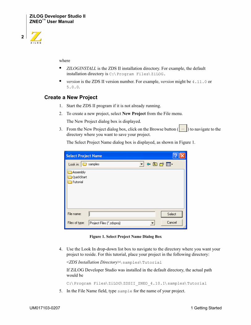
3. From the New Project dialog box, click on the Browse button ( ) to navigate to the directory where you want to save your project.
The Select Project Name dialog box is displayed, as shown in Figure 1.
Figure 1. Select Project Name Dialog Box
4. Use the Look In drop-down list box to navigate to the directory where you want your project to reside. For this tutorial, place your project in the following directory:
<ZDS Installation Directory>\samples\Tutorial
If ZiLOG Developer Studio was installed in the default directory, the actual path would be
C:\Program Files\ZiLOG\ZDSII_ZNEO_4.10.1\samples\Tutorial
5. In the File Name field, type sample for the name of your project.
UM017103-0207 1 Getting Started
ZiLOG Developer Studio IIZNEO™ User Manual
3
The ZNEO developer’s environment creates a project file. By default, project files have the .zdsproj extension (for example, <project name>.zdsproj). You do not have to type the extension .zdsproj in this field. It is added automatically.
6. Click Select to return to the New Project dialog box.
7. In the Project Type field, select Standard because the sample project uses .c files.
8. In the CPU Family drop-down list box, select Z16F_Series.
9. In the CPU drop-down list box, select Z16F2811AL.
10. In the Build Type drop-down list box, select Executable to build an application. See Figure 2.
Figure 2. New Project Dialog Box
11. Click Continue.
The New Project Wizard dialog box (Figure 3) is displayed. It allows you to modify the initial values for some of the project settings during the project creation process.
1 Getting Started UM017103-0207
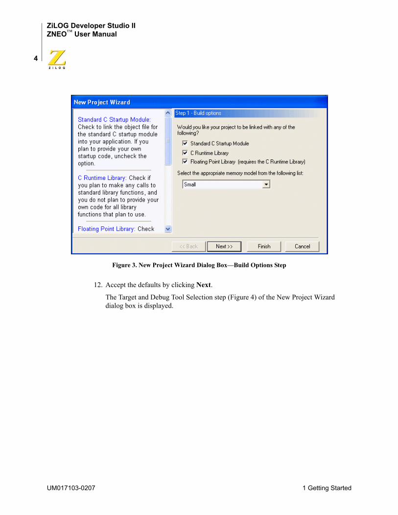
ZiLOG Developer Studio IIZNEO™ User Manual
4
Figure 3. New Project Wizard Dialog Box—Build Options Step
12. Accept the defaults by clicking Next.
The Target and Debug Tool Selection step (Figure 4) of the New Project Wizard dialog box is displayed.
UM017103-0207 1 Getting Started
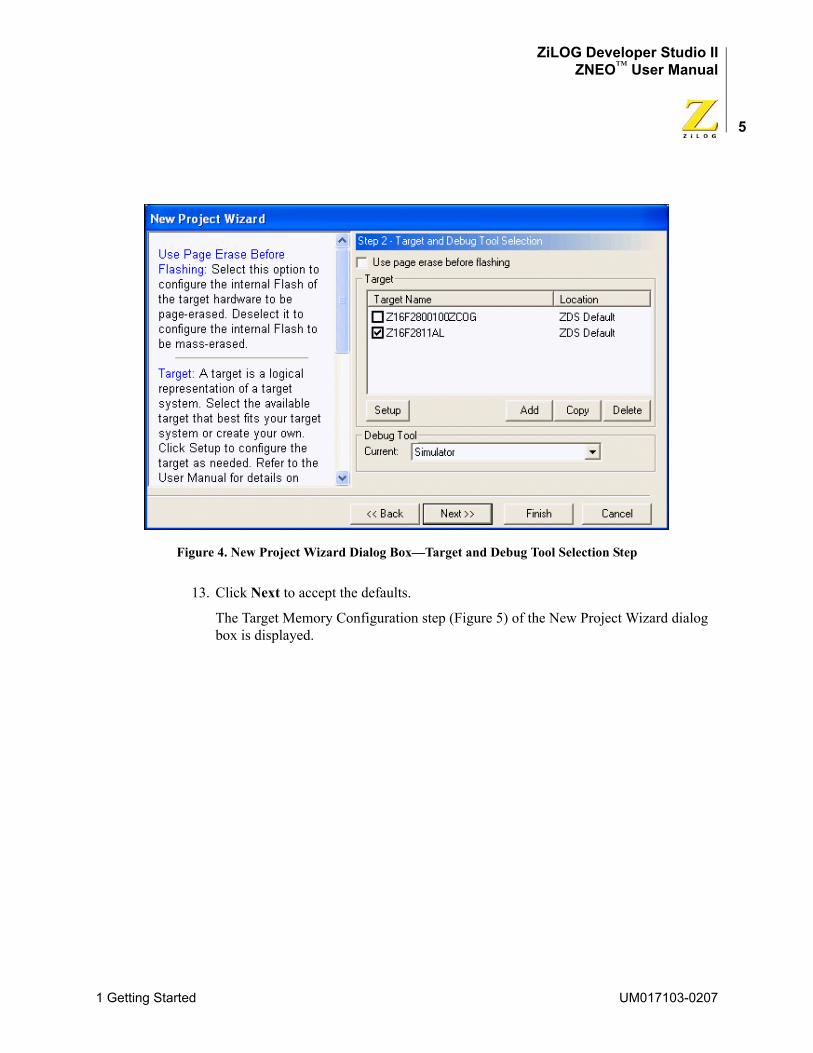
ZiLOG Developer Studio IIZNEO™ User Manual
5
Figure 4. New Project Wizard Dialog Box—Target and Debug Tool Selection Step
13. Click Next to accept the defaults.
The Target Memory Configuration step (Figure 5) of the New Project Wizard dialog box is displayed.
1 Getting Started UM017103-0207
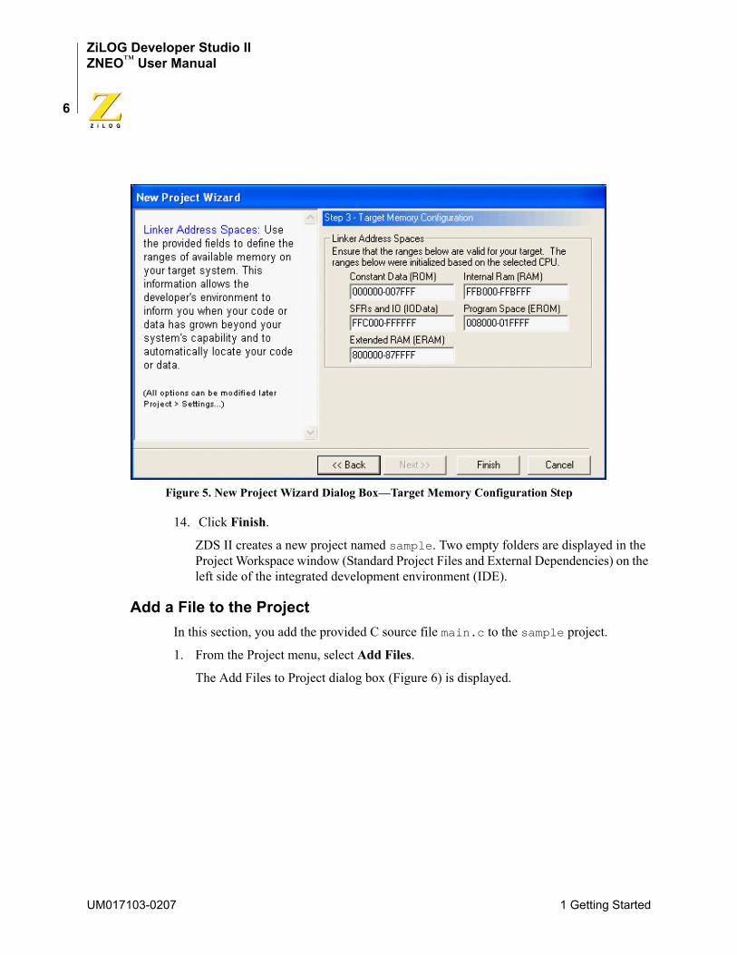
ZiLOG Developer Studio IIZNEO™ User Manual
6
Figure 5. New Project Wizard Dialog Box—Target Memory Configuration Step
14. Click Finish.
ZDS II creates a new project named sample. Two empty folders are displayed in the Project Workspace window (Standard Project Files and External Dependencies) on the left side of the integrated development environment (IDE).
Add a File to the ProjectIn this section, you add the provided C source file main.c to the sample project.
1. From the Project menu, select Add Files.
The Add Files to Project dialog box (Figure 6) is displayed.
UM017103-0207 1 Getting Started
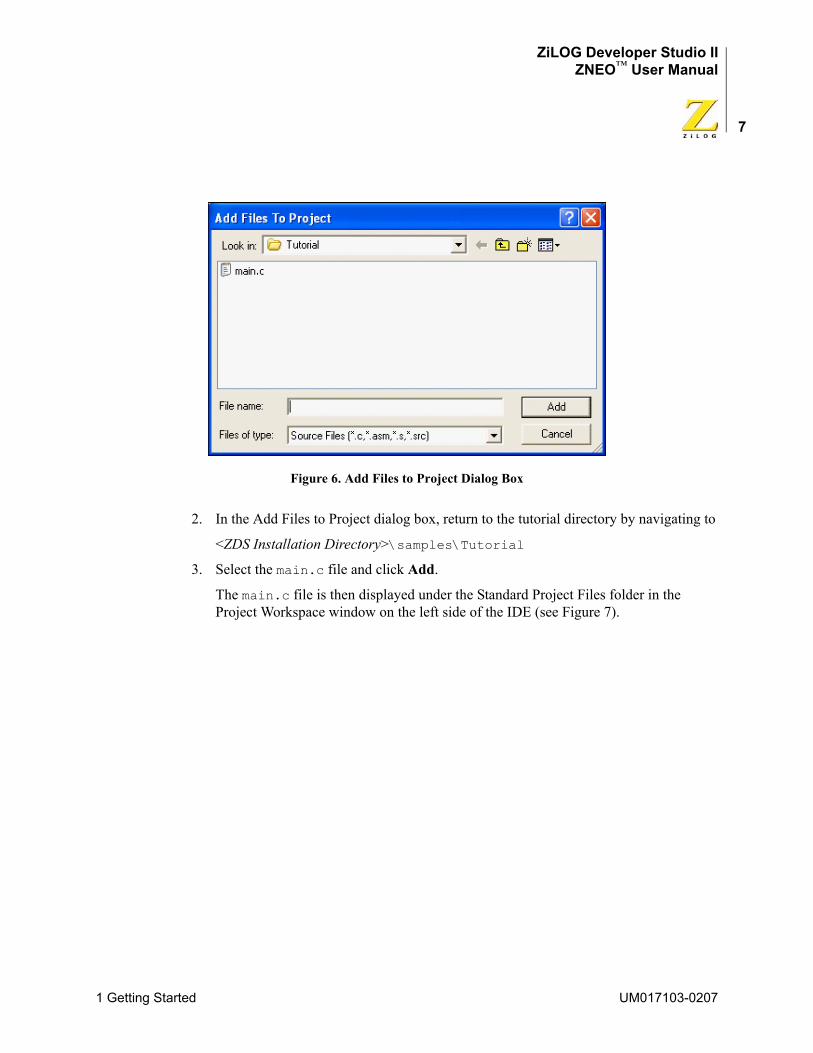
ZiLOG Developer Studio IIZNEO™ User Manual
7
Figure 6. Add Files to Project Dialog Box
2. In the Add Files to Project dialog box, return to the tutorial directory by navigating to
<ZDS Installation Directory>\samples\Tutorial
3. Select the main.c file and click Add.
The main.c file is then displayed under the Standard Project Files folder in the Project Workspace window on the left side of the IDE (see Figure 7).
1 Getting Started UM017103-0207
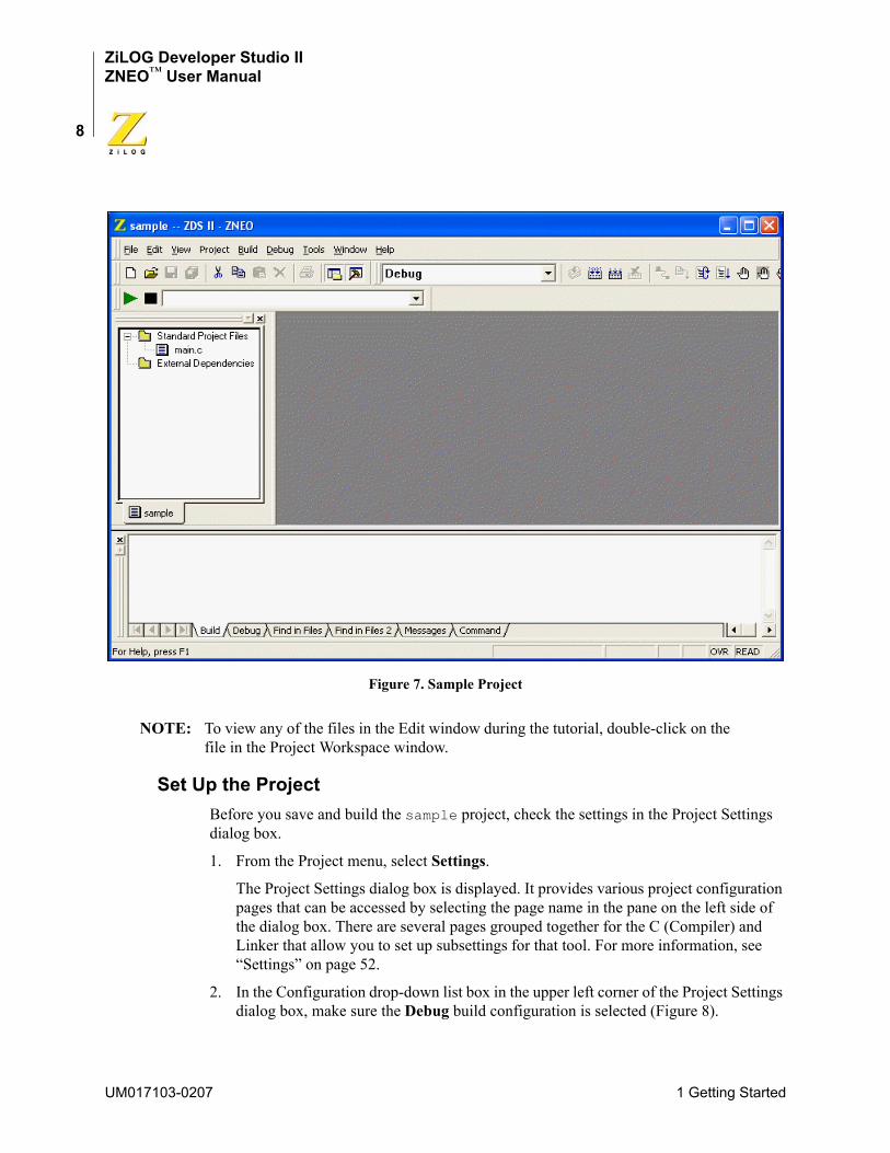
ZiLOG Developer Studio IIZNEO™ User Manual
8
Figure 7. Sample Project
NOTE: To view any of the files in the Edit window during the tutorial, double-click on the file in the Project Workspace window.
Set Up the ProjectBefore you save and build the sample project, check the settings in the Project Settings dialog box.
1. From the Project menu, select Settings.
The Project Settings dialog box is displayed. It provides various project configuration pages that can be accessed by selecting the page name in the pane on the left side of the dialog box. There are several pages grouped together for the C (Compiler) and Linker that allow you to set up subsettings for that tool. For more information, see “Settings” on page 52.
2. In the Configuration drop-down list box in the upper left corner of the Project Settings dialog box, make sure the Debug build configuration is selected (Figure 8).
UM017103-0207 1 Getting Started
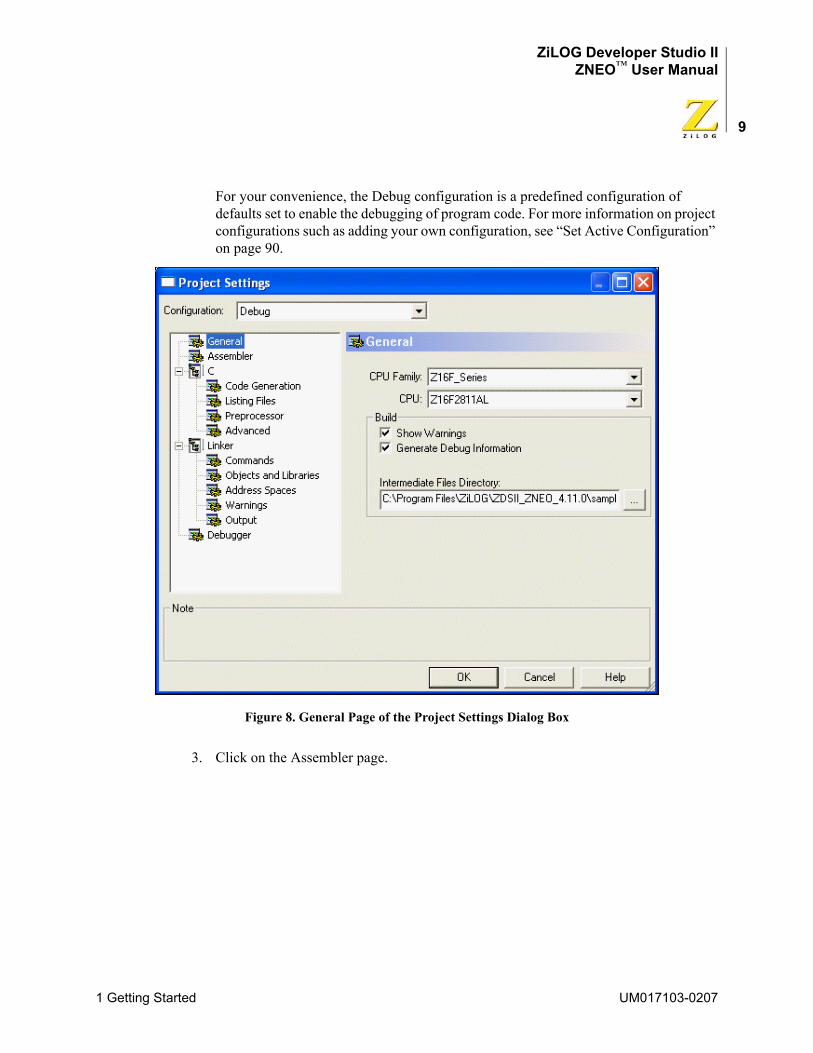
ZiLOG Developer Studio IIZNEO™ User Manual
9
For your convenience, the Debug configuration is a predefined configuration of defaults set to enable the debugging of program code. For more information on project configurations such as adding your own configuration, see “Set Active Configuration” on page 90.
Figure 8. General Page of the Project Settings Dialog Box
3. Click on the Assembler page.
1 Getting Started UM017103-0207
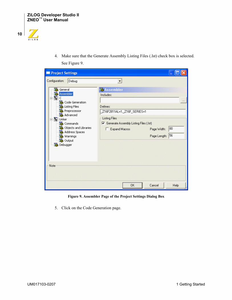
ZiLOG Developer Studio IIZNEO™ User Manual
10
4. Make sure that the Generate Assembly Listing Files (.lst) check box is selected.
See Figure 9.
Figure 9. Assembler Page of the Project Settings Dialog Box
5. Click on the Code Generation page.
UM017103-0207 1 Getting Started
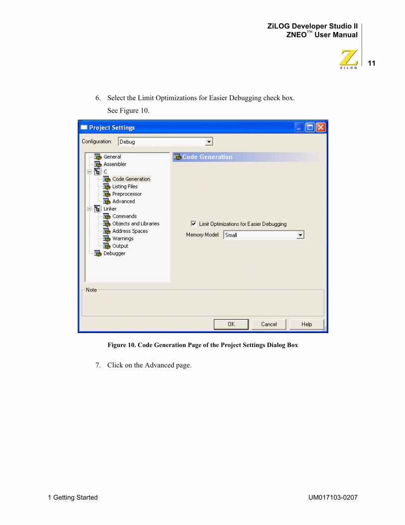
ZiLOG Developer Studio IIZNEO™ User Manual
11
6. Select the Limit Optimizations for Easier Debugging check box.
See Figure 10.
Figure 10. Code Generation Page of the Project Settings Dialog Box
7. Click on the Advanced page.
1 Getting Started UM017103-0207
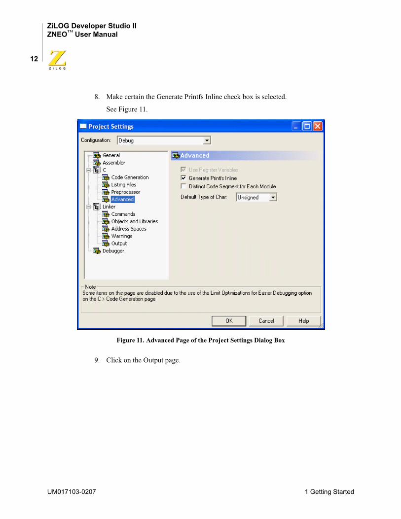
ZiLOG Developer Studio IIZNEO™ User Manual
12
8. Make certain the Generate Printfs Inline check box is selected.
See Figure 11.
Figure 11. Advanced Page of the Project Settings Dialog Box
9. Click on the Output page.
UM017103-0207 1 Getting Started
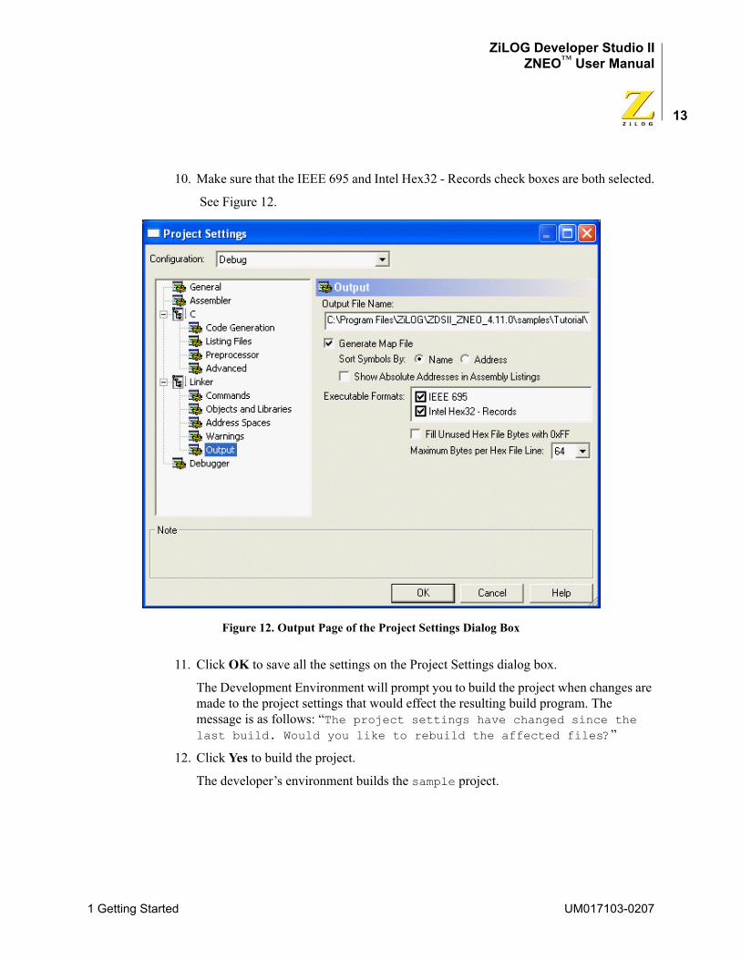
ZiLOG Developer Studio IIZNEO™ User Manual
13
10. Make sure that the IEEE 695 and Intel Hex32 - Records check boxes are both selected.
See Figure 12.
Figure 12. Output Page of the Project Settings Dialog Box
11. Click OK to save all the settings on the Project Settings dialog box.
The Development Environment will prompt you to build the project when changes are made to the project settings that would effect the resulting build program. The message is as follows: “The project settings have changed since the last build. Would you like to rebuild the affected files?”
12. Click Yes to build the project.
The developer’s environment builds the sample project.
1 Getting Started UM017103-0207
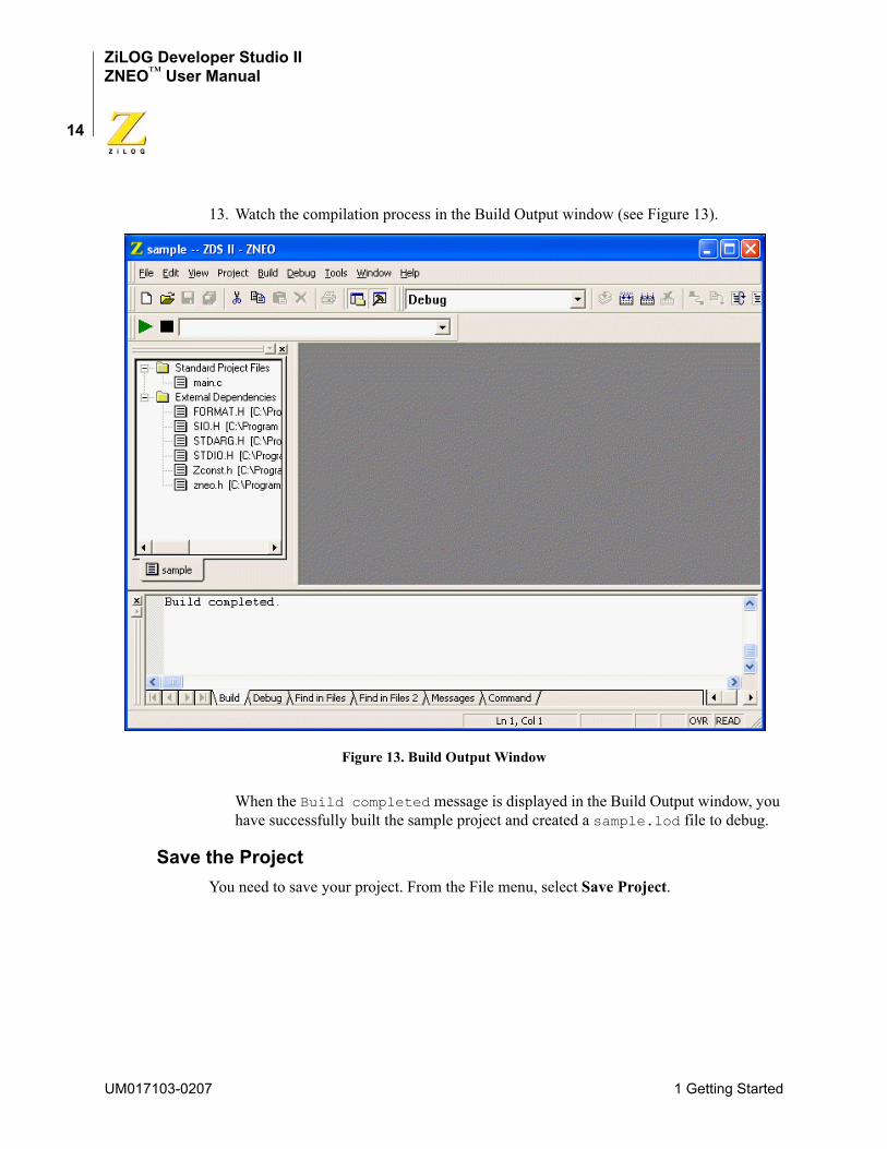
ZiLOG Developer Studio IIZNEO™ User Manual
14
13. Watch the compilation process in the Build Output window (see Figure 13).
Figure 13. Build Output Window
When the Build completed message is displayed in the Build Output window, you have successfully built the sample project and created a sample.lod file to debug.
Save the ProjectYou need to save your project. From the File menu, select Save Project.
UM017103-0207 1 Getting Started

ZiLOG Developer Studio IIZNEO™ User Manual
15
2 Using the Integrated Development Envi-ronment
This section discusses how to use the integrated development environment (IDE):
• “Toolbars” on page 16
• “Windows” on page 26
• “Menu Bar” on page 34
• “Shortcut Keys” on page 110
To effectively understand how to use the developer’s environment, be sure to go through the “Developer’s Environment Tutorial” on page 1.
After the discussion of the toolbars and windows, this section discusses the menu bar (see Figure 14) from left to right—File, Edit, View, Project, Build, Debug, Tools, Window, and Help—and the dialog boxes accessed from the menus. For example, the Project Settings dialog box is discussed as a part of the Project menu section.
2 Using the Integrated Development Environment UM017103-0207
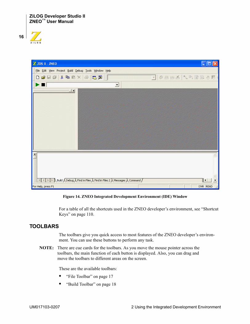
ZiLOG Developer Studio IIZNEO™ User Manual
16
Figure 14. ZNEO Integrated Development Environment (IDE) Window
For a table of all the shortcuts used in the ZNEO developer’s environment, see “Shortcut Keys” on page 110.
TOOLBARSThe toolbars give you quick access to most features of the ZNEO developer’s environ-ment. You can use these buttons to perform any task.
NOTE: There are cue cards for the toolbars. As you move the mouse pointer across the toolbars, the main function of each button is displayed. Also, you can drag and move the toolbars to different areas on the screen.
These are the available toolbars:
• “File Toolbar” on page 17
• “Build Toolbar” on page 18
UM017103-0207 2 Using the Integrated Development Environment
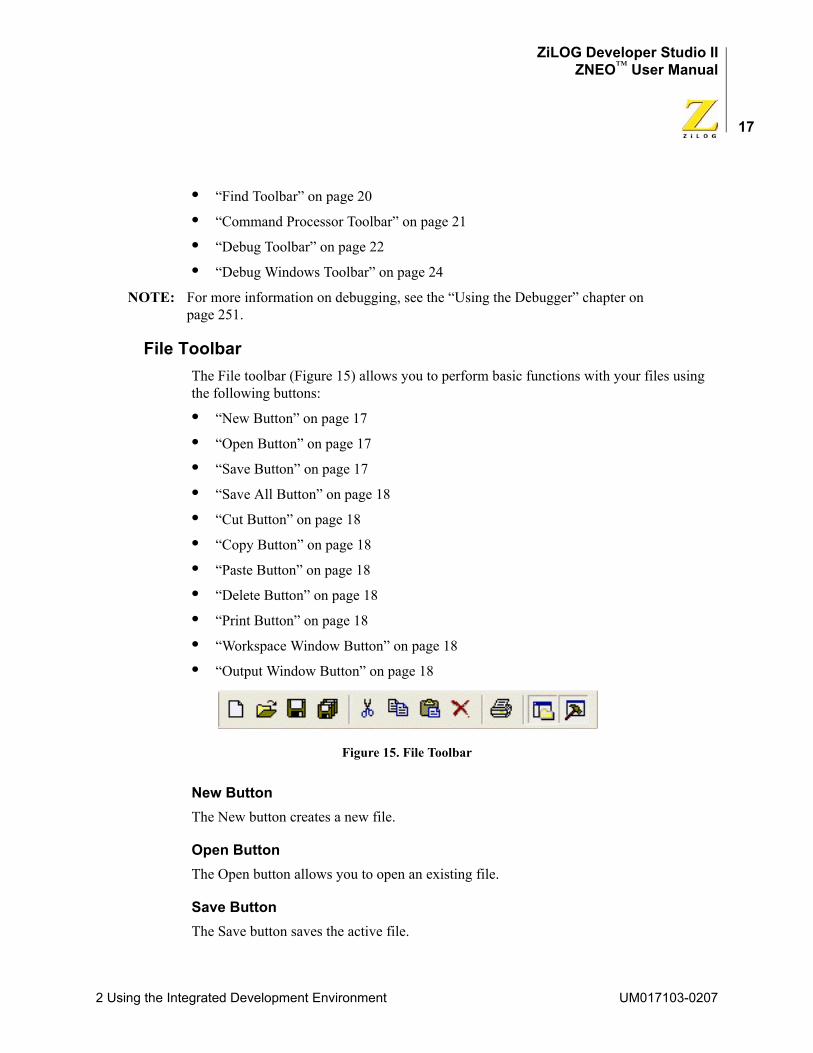
ZiLOG Developer Studio IIZNEO™ User Manual
17
• “Find Toolbar” on page 20
• “Command Processor Toolbar” on page 21
• “Debug Toolbar” on page 22
• “Debug Windows Toolbar” on page 24
NOTE: For more information on debugging, see the “Using the Debugger” chapter on page 251.
File ToolbarThe File toolbar (Figure 15) allows you to perform basic functions with your files using the following buttons:
• “New Button” on page 17
• “Open Button” on page 17
• “Save Button” on page 17
• “Save All Button” on page 18
• “Cut Button” on page 18
• “Copy Button” on page 18
• “Paste Button” on page 18
• “Delete Button” on page 18
• “Print Button” on page 18
• “Workspace Window Button” on page 18
• “Output Window Button” on page 18
Figure 15. File Toolbar
New ButtonThe New button creates a new file.
Open ButtonThe Open button allows you to open an existing file.
Save ButtonThe Save button saves the active file.
2 Using the Integrated Development Environment UM017103-0207

ZiLOG Developer Studio IIZNEO™ User Manual
18
Save All ButtonThe Save All button saves all open files and the currently loaded project.
Cut ButtonThe Cut button deletes selected text from the active file and puts it on the Windows clip-board.
Copy ButtonThe Copy button copies selected text from the active file and puts it on the Windows clip-board.
Paste ButtonThe Paste button pastes the current contents of the clipboard into the active file at the cur-rent cursor position.
Delete ButtonThe Delete button deletes selected text from the active file.
Print ButtonThe Print button prints the active file.
Workspace Window ButtonThe Workspace Window button shows or hides the Project Workspace window.
Output Window ButtonThe Output Window button shows or hides the Output window.
Build ToolbarThe Build toolbar (Figure 16) allows you to build your project, set breakpoints, and select a project configuration with the following controls and buttons:
• “Select Build Configuration List Box” on page 19
• “Compile/Assemble File Button” on page 19
• “Build Button” on page 19
• “Rebuild All Button” on page 19
• “Stop Build Button” on page 19
• “Connect to Target Button” on page 19
• “Download Code Button” on page 19
UM017103-0207 2 Using the Integrated Development Environment
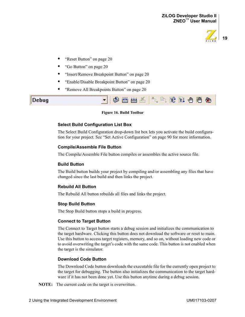
ZiLOG Developer Studio IIZNEO™ User Manual
19
• “Reset Button” on page 20
• “Go Button” on page 20
• “Insert/Remove Breakpoint Button” on page 20
• “Enable/Disable Breakpoint Button” on page 20
• “Remove All Breakpoints Button” on page 20
Figure 16. Build Toolbar
Select Build Configuration List BoxThe Select Build Configuration drop-down list box lets you activate the build configura-tion for your project. See “Set Active Configuration” on page 90 for more information.
Compile/Assemble File ButtonThe Compile/Assemble File button compiles or assembles the active source file.
Build ButtonThe Build button builds your project by compiling and/or assembling any files that have changed since the last build and then links the project.
Rebuild All ButtonThe Rebuild All button rebuilds all files and links the project.
Stop Build ButtonThe Stop Build button stops a build in progress.
Connect to Target ButtonThe Connect to Target button starts a debug session and initializes the communication to the target hardware. Clicking this button does not download the software or reset to main. Use this button to access target registers, memory, and so on, without loading new code or to avoid overwriting the target’s code with the same code. This button is not enabled when the target is the simulator.
Download Code ButtonThe Download Code button downloads the executable file for the currently open project to the target for debugging. The button also initializes the communication to the target hard-ware if it has not been done yet. Use this button anytime during a debug session.
NOTE: The current code on the target is overwritten.
2 Using the Integrated Development Environment UM017103-0207
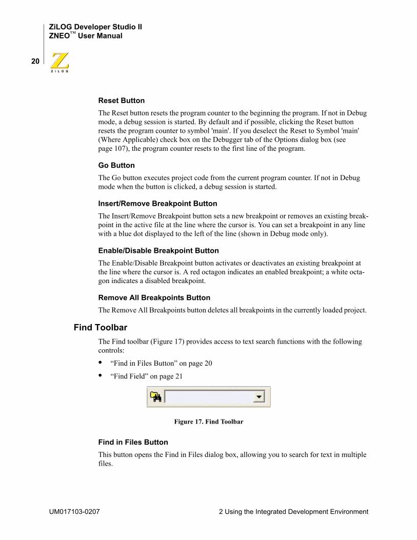
ZiLOG Developer Studio IIZNEO™ User Manual
20
Reset ButtonThe Reset button resets the program counter to the beginning the program. If not in Debug mode, a debug session is started. By default and if possible, clicking the Reset button resets the program counter to symbol 'main'. If you deselect the Reset to Symbol 'main' (Where Applicable) check box on the Debugger tab of the Options dialog box (see page 107), the program counter resets to the first line of the program.
Go ButtonThe Go button executes project code from the current program counter. If not in Debug mode when the button is clicked, a debug session is started.
Insert/Remove Breakpoint ButtonThe Insert/Remove Breakpoint button sets a new breakpoint or removes an existing break-point in the active file at the line where the cursor is. You can set a breakpoint in any line with a blue dot displayed to the left of the line (shown in Debug mode only).
Enable/Disable Breakpoint ButtonThe Enable/Disable Breakpoint button activates or deactivates an existing breakpoint at the line where the cursor is. A red octagon indicates an enabled breakpoint; a white octa-gon indicates a disabled breakpoint.
Remove All Breakpoints ButtonThe Remove All Breakpoints button deletes all breakpoints in the currently loaded project.
Find ToolbarThe Find toolbar (Figure 17) provides access to text search functions with the following controls:
• “Find in Files Button” on page 20
• “Find Field” on page 21
Figure 17. Find Toolbar
Find in Files ButtonThis button opens the Find in Files dialog box, allowing you to search for text in multiple files.
UM017103-0207 2 Using the Integrated Development Environment
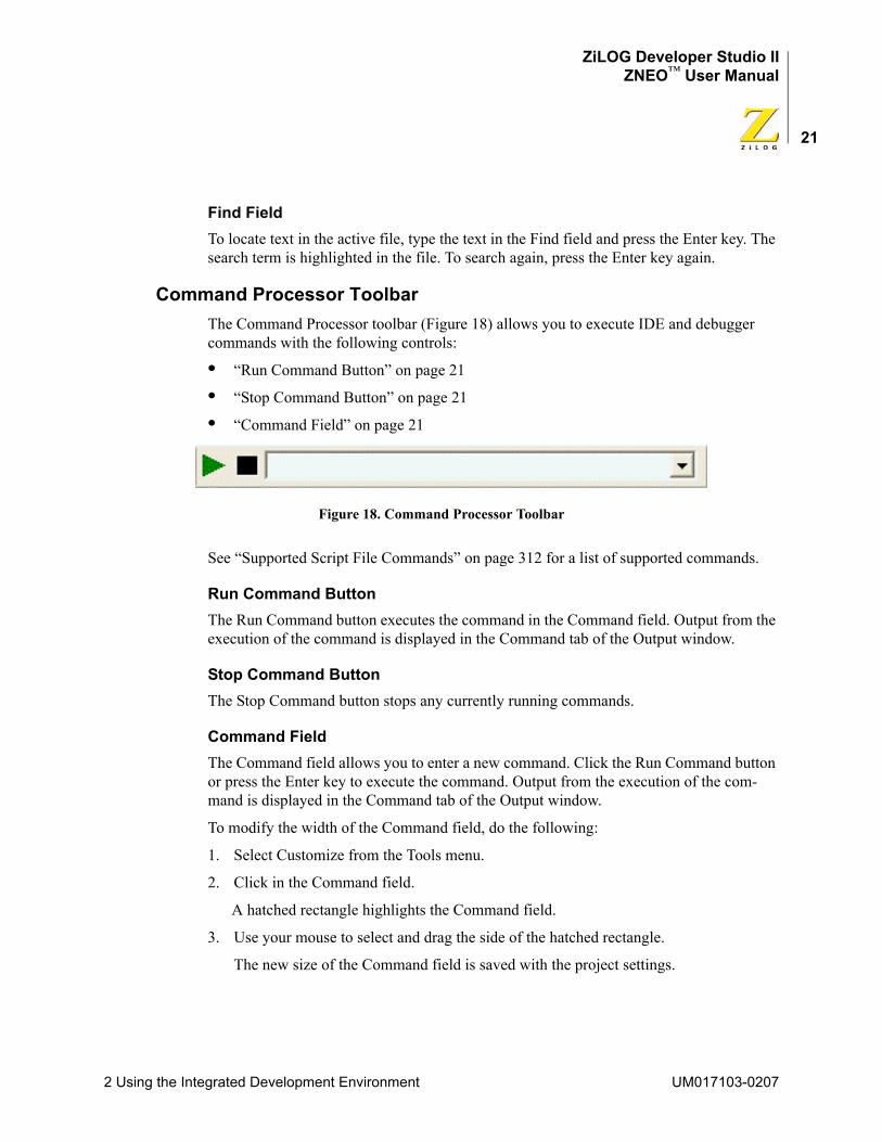
ZiLOG Developer Studio IIZNEO™ User Manual
21
Find FieldTo locate text in the active file, type the text in the Find field and press the Enter key. The search term is highlighted in the file. To search again, press the Enter key again.
Command Processor ToolbarThe Command Processor toolbar (Figure 18) allows you to execute IDE and debugger commands with the following controls:
• “Run Command Button” on page 21
• “Stop Command Button” on page 21
• “Command Field” on page 21
Figure 18. Command Processor Toolbar
See “Supported Script File Commands” on page 312 for a list of supported commands.
Run Command ButtonThe Run Command button executes the command in the Command field. Output from the execution of the command is displayed in the Command tab of the Output window.
Stop Command ButtonThe Stop Command button stops any currently running commands.
Command FieldThe Command field allows you to enter a new command. Click the Run Command button or press the Enter key to execute the command. Output from the execution of the com-mand is displayed in the Command tab of the Output window.
To modify the width of the Command field, do the following:
1. Select Customize from the Tools menu.
2. Click in the Command field.
A hatched rectangle highlights the Command field.
3. Use your mouse to select and drag the side of the hatched rectangle.
The new size of the Command field is saved with the project settings.
2 Using the Integrated Development Environment UM017103-0207
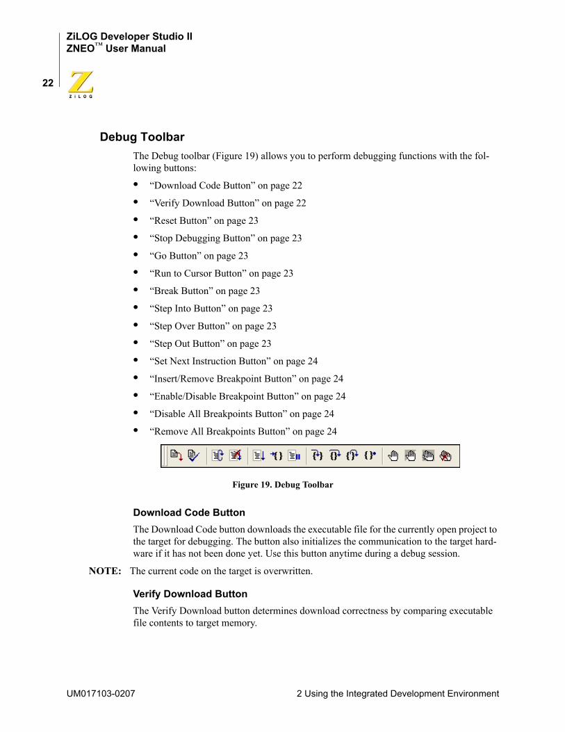
ZiLOG Developer Studio IIZNEO™ User Manual
22
Debug ToolbarThe Debug toolbar (Figure 19) allows you to perform debugging functions with the fol-lowing buttons:
• “Download Code Button” on page 22
• “Verify Download Button” on page 22
• “Reset Button” on page 23
• “Stop Debugging Button” on page 23
• “Go Button” on page 23
• “Run to Cursor Button” on page 23
• “Break Button” on page 23
• “Step Into Button” on page 23
• “Step Over Button” on page 23
• “Step Out Button” on page 23
• “Set Next Instruction Button” on page 24
• “Insert/Remove Breakpoint Button” on page 24
• “Enable/Disable Breakpoint Button” on page 24
• “Disable All Breakpoints Button” on page 24
• “Remove All Breakpoints Button” on page 24
Figure 19. Debug Toolbar
Download Code ButtonThe Download Code button downloads the executable file for the currently open project to the target for debugging. The button also initializes the communication to the target hard-ware if it has not been done yet. Use this button anytime during a debug session.
NOTE: The current code on the target is overwritten.
Verify Download ButtonThe Verify Download button determines download correctness by comparing executable file contents to target memory.
UM017103-0207 2 Using the Integrated Development Environment
ZiLOG Developer Studio IIZNEO™ User Manual
23
Reset ButtonThe Reset button resets the program counter to the beginning the program. If not in Debug mode, a debug session is started. By default and if possible, clicking the Reset button resets the program counter to symbol 'main'. If you deselect the Reset to Symbol 'main' (Where Applicable) check box on the Debugger tab of the Options dialog box (see page 107), the program counter resets to the first line of the program.
Stop Debugging ButtonThe Stop Debugging button ends the current debug session.
To stop program execution, click the Break button.
Go ButtonThe Go button executes project code from the current program counter. If not in Debug mode when the button is clicked, a debug session is started.
Run to Cursor ButtonThe Run to Cursor button executes the program code from the current program counter to the line containing the cursor in the active file or the Disassembly window. The cursor must be placed on a valid code line (a C source line with a blue dot displayed in the gutter or any instruction line in the Disassembly window).
Break ButtonThe Break button stops program execution at the current program counter.
Step Into ButtonThe Step Into button executes one statement or instruction from the current program counter, following the execution into function calls. When complete, the program counter resides at the next program statement or instruction unless a function was entered, in which case the program counter resides at the first statement or instruction in the function.
Step Over ButtonThe Step Over button executes one statement or instruction from the current program counter without following the execution into function calls. When complete, the program counter resides at the next program statement or instruction.
Step Out ButtonThe Step Out button executes the remaining statements or instructions in the current func-tion and returns to the statement or instruction following the call to the current function.
2 Using the Integrated Development Environment UM017103-0207
ZiLOG Developer Studio IIZNEO™ User Manual
24
Set Next Instruction ButtonThe Set Next Instruction button sets the program counter to the line containing the cursor in the active file or the Disassembly window.
Insert/Remove Breakpoint ButtonThe Insert/Remove Breakpoint button sets a new breakpoint or removes an existing break-point at the line containing the cursor in the active file or the Disassembly window. A breakpoint must be placed on a valid code line (a C source line with a blue dot displayed in the gutter or any instruction line in the Disassembly window). For more information on breakpoints, see “Using Breakpoints” on page 293.
Enable/Disable Breakpoint ButtonThe Enable/Disable Breakpoint button activates or deactivates the existing breakpoint at the line containing the cursor in the active file or the Disassembly window. A red octagon indicates an enabled breakpoint; a white octagon indicates a disabled breakpoint. For more information on breakpoints, see “Using Breakpoints” on page 293.
Disable All Breakpoints ButtonThe Disable All Breakpoints button deactivates all breakpoints in the currently loaded project. To remove breakpoints from your program, use the Remove All Breakpoints but-ton.
Remove All Breakpoints ButtonThe Remove All Breakpoints button deletes all breakpoints in the currently loaded project. To deactivate breakpoints in your project, use the Disable All Breakpoints button.
Debug Windows ToolbarThe Debug Windows toolbar (Figure 20) allows you to display the Debug windows with the following buttons:
• “Registers Window Button” on page 25
• “Special Function Registers Window Button” on page 25
• “Clock Window Button” on page 25
• “Memory Window Button” on page 25
• “Watch Window Button” on page 25
• “Locals Window Button” on page 25
• “Call Stack Window Button” on page 25
• “Symbols Window Button” on page 25
• “Disassembly Window Button” on page 26
UM017103-0207 2 Using the Integrated Development Environment
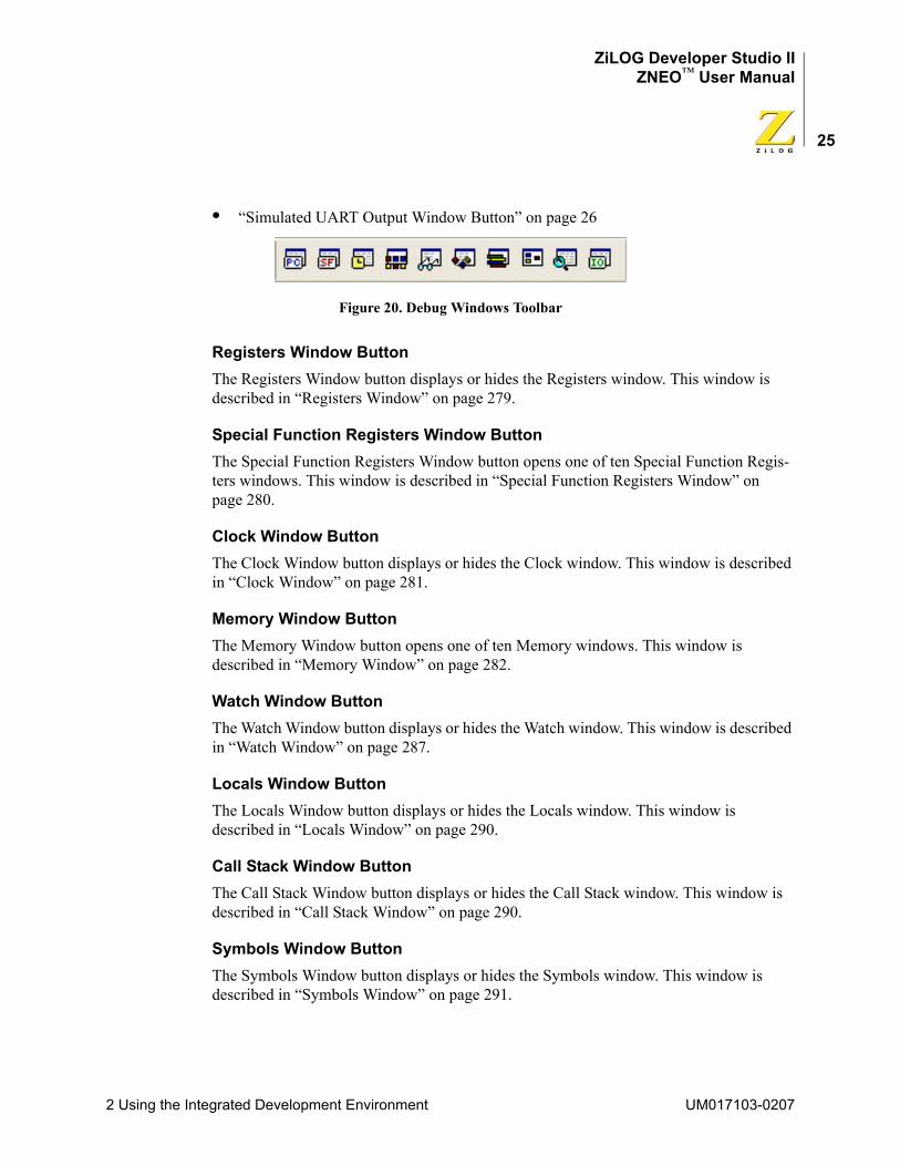
ZiLOG Developer Studio IIZNEO™ User Manual
25
• “Simulated UART Output Window Button” on page 26
Figure 20. Debug Windows Toolbar
Registers Window ButtonThe Registers Window button displays or hides the Registers window. This window is described in “Registers Window” on page 279.
Special Function Registers Window ButtonThe Special Function Registers Window button opens one of ten Special Function Regis-ters windows. This window is described in “Special Function Registers Window” on page 280.
Clock Window ButtonThe Clock Window button displays or hides the Clock window. This window is described in “Clock Window” on page 281.
Memory Window ButtonThe Memory Window button opens one of ten Memory windows. This window is described in “Memory Window” on page 282.
Watch Window ButtonThe Watch Window button displays or hides the Watch window. This window is described in “Watch Window” on page 287.
Locals Window ButtonThe Locals Window button displays or hides the Locals window. This window is described in “Locals Window” on page 290.
Call Stack Window ButtonThe Call Stack Window button displays or hides the Call Stack window. This window is described in “Call Stack Window” on page 290.
Symbols Window ButtonThe Symbols Window button displays or hides the Symbols window. This window is described in “Symbols Window” on page 291.
2 Using the Integrated Development Environment UM017103-0207
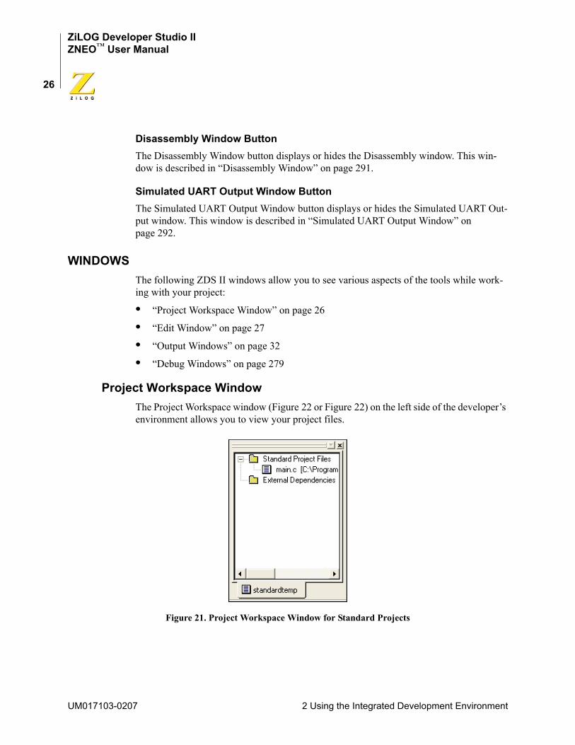
ZiLOG Developer Studio IIZNEO™ User Manual
26
Disassembly Window ButtonThe Disassembly Window button displays or hides the Disassembly window. This win-dow is described in “Disassembly Window” on page 291.
Simulated UART Output Window ButtonThe Simulated UART Output Window button displays or hides the Simulated UART Out-put window. This window is described in “Simulated UART Output Window” on page 292.
WINDOWSThe following ZDS II windows allow you to see various aspects of the tools while work-ing with your project:
• “Project Workspace Window” on page 26
• “Edit Window” on page 27
• “Output Windows” on page 32
• “Debug Windows” on page 279
Project Workspace WindowThe Project Workspace window (Figure 22 or Figure 22) on the left side of the developer’s environment allows you to view your project files.
Figure 21. Project Workspace Window for Standard Projects
UM017103-0207 2 Using the Integrated Development Environment

ZiLOG Developer Studio IIZNEO™ User Manual
27
Figure 22. Project Workspace Window for Assembly Only Projects
The Project Workspace window provides access to related functions using context menus. To access context menus, right-click a file or folder in the window. Depending on which file or folder is highlighted, the context menu provides some or all of the following func-tions:
• Dock the Project Workspace window
• Hide the Project Workspace window
• Add files to the project
• Remove the highlighted file(s) from the project
• Build project files or external dependencies
• Build or compile the highlighted file
• Undock the Project Workspace window, allowing it to float in the Edit window
Edit WindowThe Edit window area (Figure 23) on the right side of the developer’s environment allows you to edit the files in your project.
2 Using the Integrated Development Environment UM017103-0207
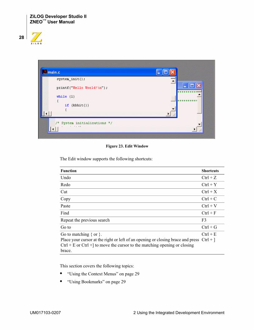
ZiLOG Developer Studio IIZNEO™ User Manual
28
Figure 23. Edit Window
The Edit window supports the following shortcuts:
This section covers the following topics:
• “Using the Context Menus” on page 29
• “Using Bookmarks” on page 29
Function Shortcuts
Undo Ctrl + ZRedo Ctrl + YCut Ctrl + XCopy Ctrl + CPaste Ctrl + VFind Ctrl + FRepeat the previous search F3Go to Ctrl + GGo to matching { or }. Place your cursor at the right or left of an opening or closing brace and press Ctrl + E or Ctrl +] to move the cursor to the matching opening or closing brace.
Ctrl + ECtrl + ]
UM017103-0207 2 Using the Integrated Development Environment
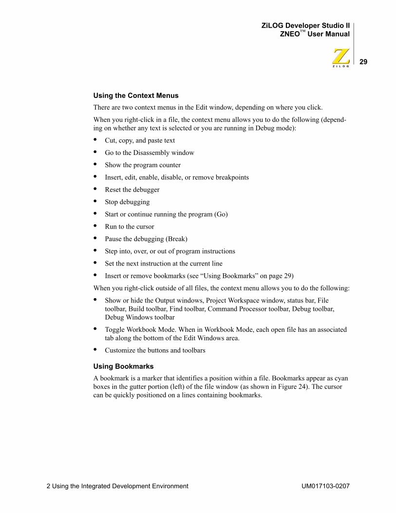
ZiLOG Developer Studio IIZNEO™ User Manual
29
Using the Context MenusThere are two context menus in the Edit window, depending on where you click.
When you right-click in a file, the context menu allows you to do the following (depend-ing on whether any text is selected or you are running in Debug mode):
• Cut, copy, and paste text
• Go to the Disassembly window
• Show the program counter
• Insert, edit, enable, disable, or remove breakpoints
• Reset the debugger
• Stop debugging
• Start or continue running the program (Go)
• Run to the cursor
• Pause the debugging (Break)
• Step into, over, or out of program instructions
• Set the next instruction at the current line
• Insert or remove bookmarks (see “Using Bookmarks” on page 29)
When you right-click outside of all files, the context menu allows you to do the following:
• Show or hide the Output windows, Project Workspace window, status bar, File toolbar, Build toolbar, Find toolbar, Command Processor toolbar, Debug toolbar, Debug Windows toolbar
• Toggle Workbook Mode. When in Workbook Mode, each open file has an associated tab along the bottom of the Edit Windows area.
• Customize the buttons and toolbars
Using BookmarksA bookmark is a marker that identifies a position within a file. Bookmarks appear as cyan boxes in the gutter portion (left) of the file window (as shown in Figure 24). The cursor can be quickly positioned on a lines containing bookmarks.
2 Using the Integrated Development Environment UM017103-0207
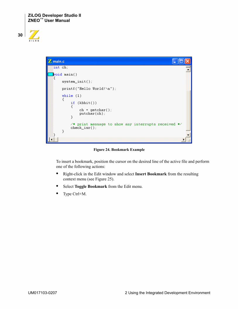
ZiLOG Developer Studio IIZNEO™ User Manual
30
Figure 24. Bookmark Example
To insert a bookmark, position the cursor on the desired line of the active file and perform one of the following actions:
• Right-click in the Edit window and select Insert Bookmark from the resulting context menu (see Figure 25).
• Select Toggle Bookmark from the Edit menu.
• Type Ctrl+M.
UM017103-0207 2 Using the Integrated Development Environment
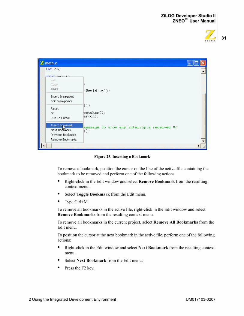
ZiLOG Developer Studio IIZNEO™ User Manual
31
Figure 25. Inserting a Bookmark
To remove a bookmark, position the cursor on the line of the active file containing the bookmark to be removed and perform one of the following actions:
• Right-click in the Edit window and select Remove Bookmark from the resulting context menu.
• Select Toggle Bookmark from the Edit menu.
• Type Ctrl+M.
To remove all bookmarks in the active file, right-click in the Edit window and select Remove Bookmarks from the resulting context menu.
To remove all bookmarks in the current project, select Remove All Bookmarks from the Edit menu.
To position the cursor at the next bookmark in the active file, perform one of the following actions:
• Right-click in the Edit window and select Next Bookmark from the resulting context menu.
• Select Next Bookmark from the Edit menu.
• Press the F2 key.
2 Using the Integrated Development Environment UM017103-0207
ZiLOG Developer Studio IIZNEO™ User Manual
32
The cursor moves forward through the file, starting at its current position and beginning again when the end of file is reached, until a bookmark is encountered. If no bookmarks are set in the active file, this function has no effect.
To position the cursor at the previous bookmark in the active file, perform one of the fol-lowing actions:
• Right-click in the Edit window and select Previous Bookmark from the resulting context menu.
• Select Previous Bookmark from the Edit menu.
• Type Shift+F2.
The cursor moves backwards through the file, starting at its current position and starting again at the end of the file when the file beginning is reached, until a bookmark is encountered. If no bookmarks are set in the active file, this function has no effect.
Output WindowsThe Output windows display output, errors, and other feedback from various components of the Integrated Development Environment.
Select one of the tabs at the bottom of the Output window to select one of the Output win-dows:
• “Build Output Window” on page 32
• “Debug Output Window” on page 33
• “Find in Files Output Windows” on page 33
• “Messages Output Window” on page 34
• “Command Output Window” on page 34
To dock the Output window with another window, click and hold the window's grip bar and then move the window.
Double-click on the window's grip bar to cause it to become a floating window.
Double-click on the floating window's title bar to change it to a dockable window.
Use the context menu to copy text from or to delete all text in the Output window.
Build Output WindowThe Build Output window (Figure 26) holds all text messages generated by the compiler, assembler, librarian, and linker, including error and warning messages.
UM017103-0207 2 Using the Integrated Development Environment
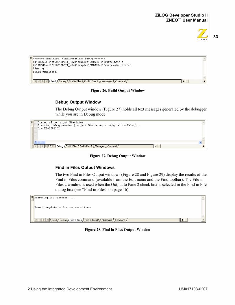
ZiLOG Developer Studio IIZNEO™ User Manual
33
Figure 26. Build Output Window
Debug Output WindowThe Debug Output window (Figure 27) holds all text messages generated by the debugger while you are in Debug mode.
Figure 27. Debug Output Window
Find in Files Output WindowsThe two Find in Files Output windows (Figure 28 and Figure 29) display the results of the Find in Files command (available from the Edit menu and the Find toolbar). The File in Files 2 window is used when the Output to Pane 2 check box is selected in the Find in File dialog box (see “Find in Files” on page 46).
Figure 28. Find in Files Output Window
2 Using the Integrated Development Environment UM017103-0207
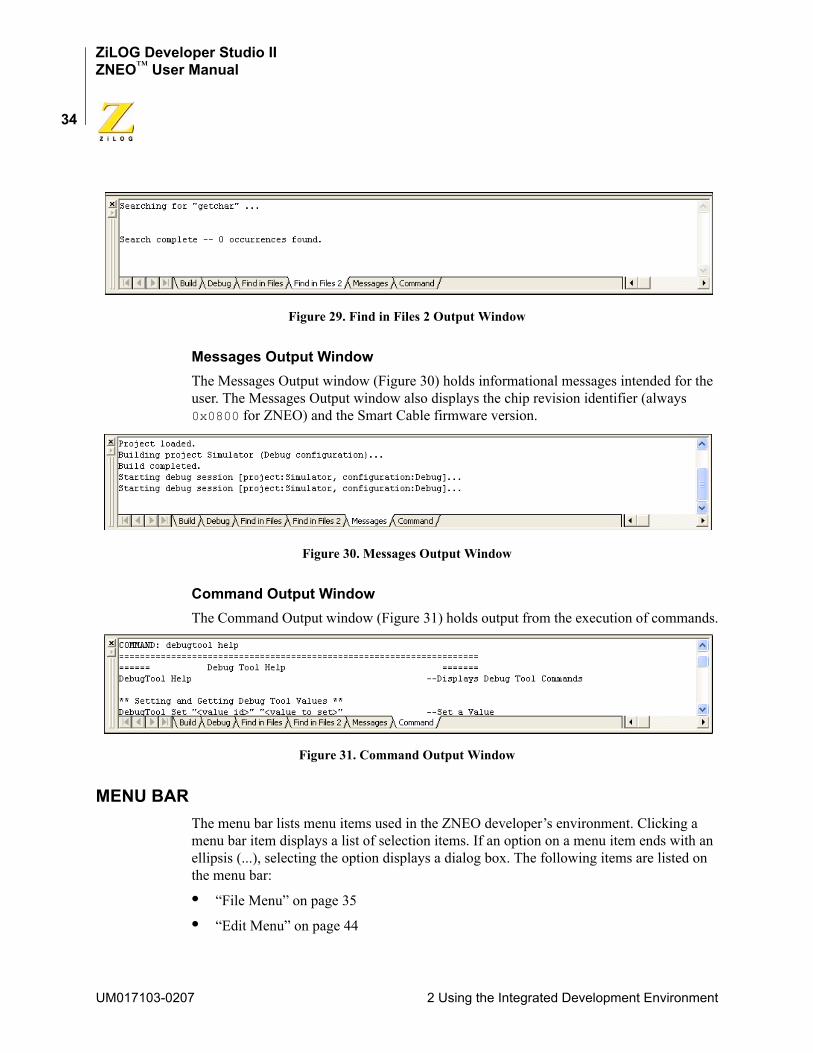
ZiLOG Developer Studio IIZNEO™ User Manual
34
Figure 29. Find in Files 2 Output Window
Messages Output WindowThe Messages Output window (Figure 30) holds informational messages intended for the user. The Messages Output window also displays the chip revision identifier (always 0x0800 for ZNEO) and the Smart Cable firmware version.
Figure 30. Messages Output Window
Command Output WindowThe Command Output window (Figure 31) holds output from the execution of commands.
Figure 31. Command Output Window
MENU BARThe menu bar lists menu items used in the ZNEO developer’s environment. Clicking a menu bar item displays a list of selection items. If an option on a menu item ends with an ellipsis (...), selecting the option displays a dialog box. The following items are listed on the menu bar:
• “File Menu” on page 35
• “Edit Menu” on page 44
UM017103-0207 2 Using the Integrated Development Environment
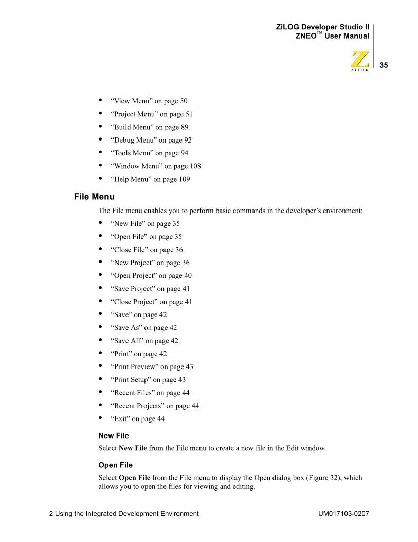
ZiLOG Developer Studio IIZNEO™ User Manual
35
• “View Menu” on page 50
• “Project Menu” on page 51
• “Build Menu” on page 89
• “Debug Menu” on page 92
• “Tools Menu” on page 94
• “Window Menu” on page 108
• “Help Menu” on page 109
File MenuThe File menu enables you to perform basic commands in the developer’s environment:
• “New File” on page 35
• “Open File” on page 35
• “Close File” on page 36
• “New Project” on page 36
• “Open Project” on page 40
• “Save Project” on page 41
• “Close Project” on page 41
• “Save” on page 42
• “Save As” on page 42
• “Save All” on page 42
• “Print” on page 42
• “Print Preview” on page 43
• “Print Setup” on page 43
• “Recent Files” on page 44
• “Recent Projects” on page 44
• “Exit” on page 44
New FileSelect New File from the File menu to create a new file in the Edit window.
Open FileSelect Open File from the File menu to display the Open dialog box (Figure 32), which allows you to open the files for viewing and editing.
2 Using the Integrated Development Environment UM017103-0207
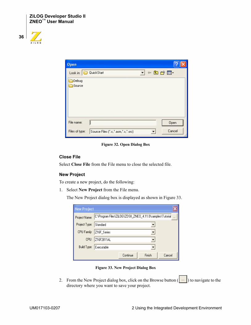
ZiLOG Developer Studio IIZNEO™ User Manual
36
Figure 32. Open Dialog Box
Close FileSelect Close File from the File menu to close the selected file.
New ProjectTo create a new project, do the following:
1. Select New Project from the File menu.
The New Project dialog box is displayed as shown in Figure 33.
Figure 33. New Project Dialog Box
2. From the New Project dialog box, click on the Browse button ( ) to navigate to the directory where you want to save your project.
UM017103-0207 2 Using the Integrated Development Environment
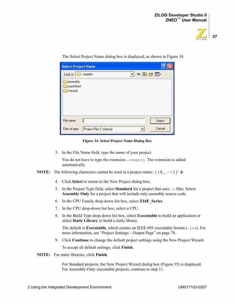
ZiLOG Developer Studio IIZNEO™ User Manual
37
The Select Project Name dialog box is displayed, as shown in Figure 34.
Figure 34. Select Project Name Dialog Box
3. In the File Name field, type the name of your project.
You do not have to type the extension .zdsproj. The extension is added automatically.
NOTE: The following characters cannot be used in a project name: ( ) $ , . - + [ ] ' &
4. Click Select to return to the New Project dialog box.
5. In the Project Type field, select Standard for a project that uses .c files. Select Assembly Only for a project that will include only assembly source code.
6. In the CPU Family drop-down list box, select Z16F_Series.
7. In the CPU drop-down list box, select a CPU.
8. In the Build Type drop-down list box, select Executable to build an application or select Static Library to build a static library.
The default is Executable, which creates an IEEE 695 executable format (.lod). For more information, see “Project Settings—Output Page” on page 78.
9. Click Continue to change the default project settings using the New Project Wizard.
To accept all default settings, click Finish.
NOTE: For static libraries, click Finish.
For Standard projects, the New Project Wizard dialog box (Figure 35) is displayed. For Assembly-Only executable projects, continue to step 11.
2 Using the Integrated Development Environment UM017103-0207
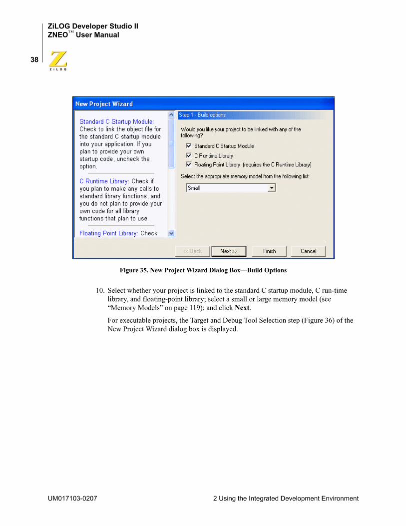
ZiLOG Developer Studio IIZNEO™ User Manual
38
Figure 35. New Project Wizard Dialog Box—Build Options
10. Select whether your project is linked to the standard C startup module, C run-time library, and floating-point library; select a small or large memory model (see “Memory Models” on page 119); and click Next.
For executable projects, the Target and Debug Tool Selection step (Figure 36) of the New Project Wizard dialog box is displayed.
UM017103-0207 2 Using the Integrated Development Environment
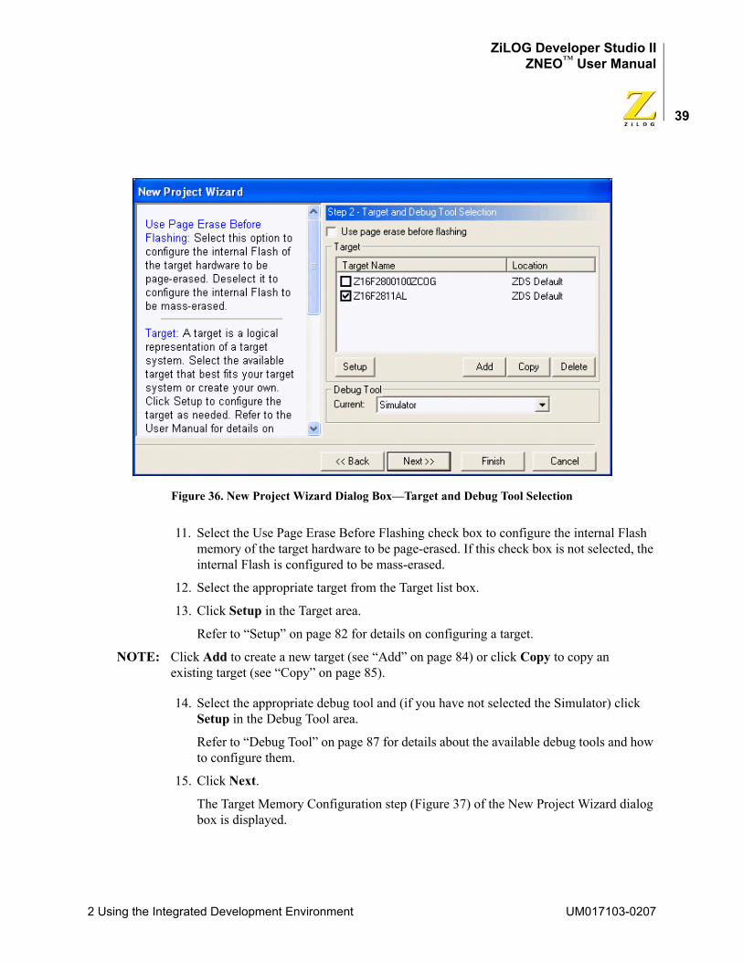
ZiLOG Developer Studio IIZNEO™ User Manual
39
Figure 36. New Project Wizard Dialog Box—Target and Debug Tool Selection
11. Select the Use Page Erase Before Flashing check box to configure the internal Flash memory of the target hardware to be page-erased. If this check box is not selected, the internal Flash is configured to be mass-erased.
12. Select the appropriate target from the Target list box.
13. Click Setup in the Target area.
Refer to “Setup” on page 82 for details on configuring a target.
NOTE: Click Add to create a new target (see “Add” on page 84) or click Copy to copy an existing target (see “Copy” on page 85).
14. Select the appropriate debug tool and (if you have not selected the Simulator) click Setup in the Debug Tool area.
Refer to “Debug Tool” on page 87 for details about the available debug tools and how to configure them.
15. Click Next.
The Target Memory Configuration step (Figure 37) of the New Project Wizard dialog box is displayed.
2 Using the Integrated Development Environment UM017103-0207
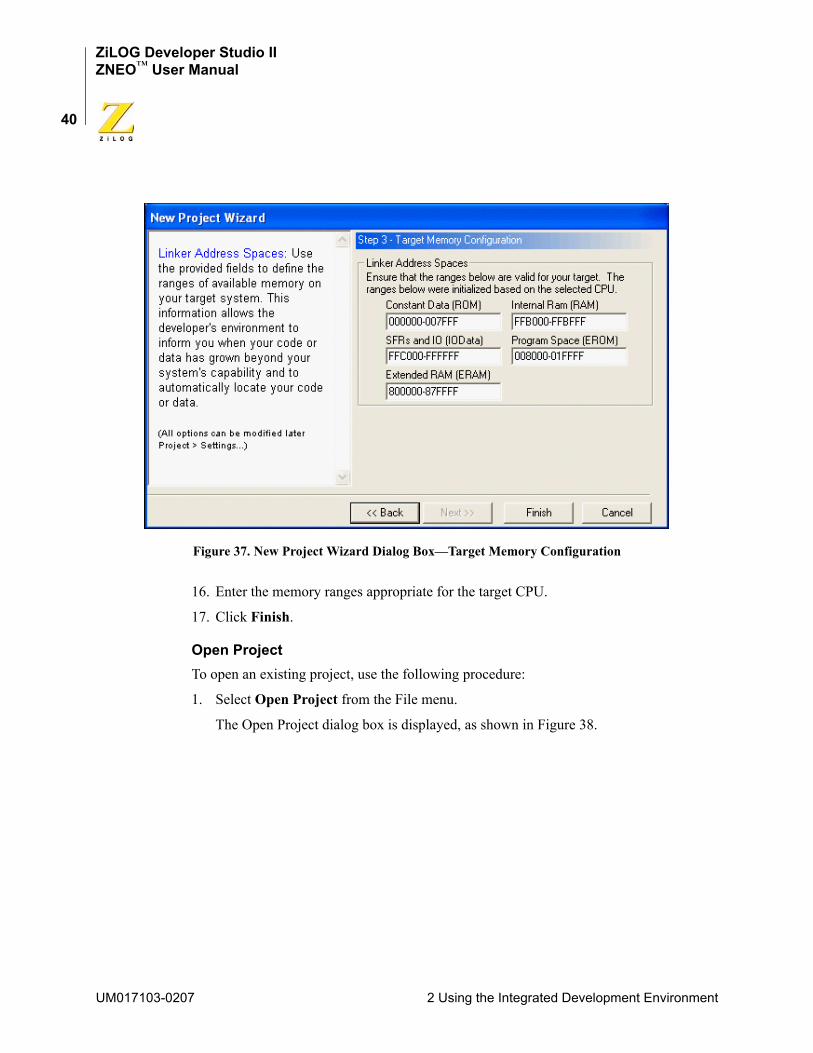
ZiLOG Developer Studio IIZNEO™ User Manual
40
Figure 37. New Project Wizard Dialog Box—Target Memory Configuration
16. Enter the memory ranges appropriate for the target CPU.
17. Click Finish.
Open ProjectTo open an existing project, use the following procedure:
1. Select Open Project from the File menu.
The Open Project dialog box is displayed, as shown in Figure 38.
UM017103-0207 2 Using the Integrated Development Environment
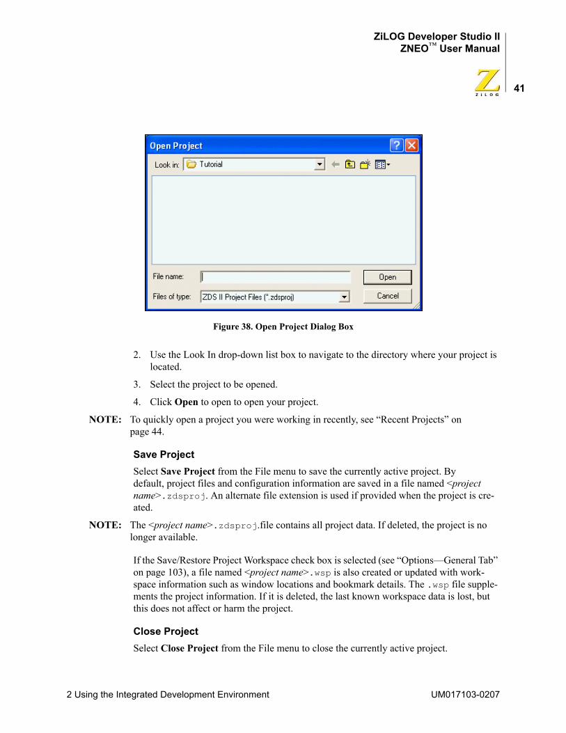
ZiLOG Developer Studio IIZNEO™ User Manual
41
Figure 38. Open Project Dialog Box
2. Use the Look In drop-down list box to navigate to the directory where your project is located.
3. Select the project to be opened.
4. Click Open to open to open your project.
NOTE: To quickly open a project you were working in recently, see “Recent Projects” on page 44.
Save ProjectSelect Save Project from the File menu to save the currently active project. By default, project files and configuration information are saved in a file named <project name>.zdsproj. An alternate file extension is used if provided when the project is cre-ated.
NOTE: The <project name>.zdsproj.file contains all project data. If deleted, the project is no longer available.
If the Save/Restore Project Workspace check box is selected (see “Options—General Tab” on page 103), a file named <project name>.wsp is also created or updated with work-space information such as window locations and bookmark details. The .wsp file supple-ments the project information. If it is deleted, the last known workspace data is lost, but this does not affect or harm the project.
Close ProjectSelect Close Project from the File menu to close the currently active project.
2 Using the Integrated Development Environment UM017103-0207
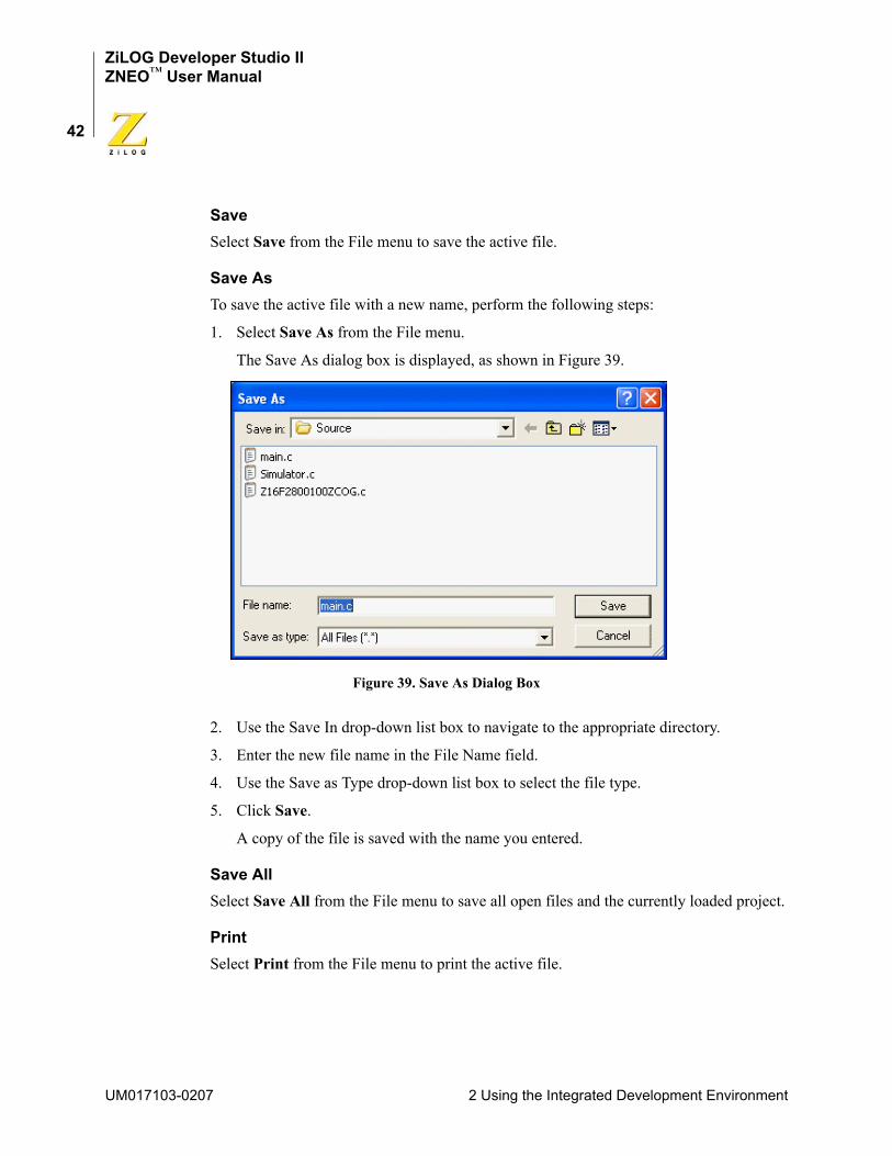
ZiLOG Developer Studio IIZNEO™ User Manual
42
SaveSelect Save from the File menu to save the active file.
Save AsTo save the active file with a new name, perform the following steps:
1. Select Save As from the File menu.
The Save As dialog box is displayed, as shown in Figure 39.
Figure 39. Save As Dialog Box
2. Use the Save In drop-down list box to navigate to the appropriate directory.
3. Enter the new file name in the File Name field.
4. Use the Save as Type drop-down list box to select the file type.
5. Click Save.
A copy of the file is saved with the name you entered.
Save AllSelect Save All from the File menu to save all open files and the currently loaded project.
PrintSelect Print from the File menu to print the active file.
UM017103-0207 2 Using the Integrated Development Environment

ZiLOG Developer Studio IIZNEO™ User Manual
43
Print PreviewSelect Print Preview from the File menu to display the file you want to print in Preview mode in a new window.
1. In the Edit window, highlight the file you want to show a Print Preview.
2. From the File menu, select Print Preview. The file is shown in Print Preview in a new window. As shown in Figure 40, main.c is in Print Preview mode.
Figure 40. Print Preview Window
3. To print the file, click Print.
To cancel the print preview, click Close. The file returns to its edit mode in the Edit window.
Print SetupSelect Print Setup from the File menu to display the Print Setup dialog box, which allows you to determine the printer’s setup before you print the file.
2 Using the Integrated Development Environment UM017103-0207
ZiLOG Developer Studio IIZNEO™ User Manual
44
Recent FilesSelect Recent Files from the File menu and then select a file from the resulting submenu to open a recently opened file.
Recent ProjectsSelect Recent Projects from the File menu and then select a project file from the resulting submenu to quickly open a recently opened project.
ExitSelect Exit from the File menu to exit the application.
Edit MenuThe Edit menu provides access to basic editing, text search, and breakpoint and bookmark manipulation features. The following options are available:
• “Undo” on page 45
• “Redo” on page 45
• “Cut” on page 45
• “Copy” on page 45
• “Paste” on page 45
• “Delete” on page 45
• “Select All” on page 45
• “Show Whitespaces” on page 45
• “Find” on page 45
• “Find Again” on page 46
• “Find in Files” on page 46
• “Replace” on page 47
• “Go to Line” on page 48
• “Manage Breakpoints” on page 49
• “Toggle Bookmark” on page 50
• “Next Bookmark” on page 50
• “Previous Bookmark” on page 50
• “Remove All Bookmarks” on page 50
UM017103-0207 2 Using the Integrated Development Environment
ZiLOG Developer Studio IIZNEO™ User Manual
45
UndoSelect Undo from the Edit menu to undo the last edit made to the active file.
RedoSelect Redo from the Edit menu to redo the last edit made to the active file.
CutSelect Cut from the Edit menu to delete selected text from the active file and put it on the Windows clipboard.
CopySelect Copy from the Edit menu to copy selected text from the active file and put it on the Windows clipboard.
PasteSelect Paste from the Edit menu to paste the current contents of the clipboard into the active file at the current cursor position.
DeleteSelect Delete from the Edit menu to delete selected text from the active file.
Select AllSelect Select All from the Edit menu to highlight all text in the active file.
Show WhitespacesSelect Show Whitespaces from the Edit menu to display all whitespace characters like spaces and tabs in the active file.
FindTo find text in the active file, use the following procedure:
1. Select Find from the Edit menu.
The Find dialog box is displayed as shown in Figure 41.
2 Using the Integrated Development Environment UM017103-0207
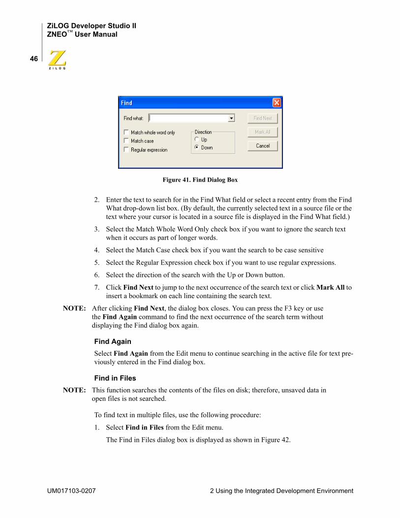
ZiLOG Developer Studio IIZNEO™ User Manual
46
Figure 41. Find Dialog Box
2. Enter the text to search for in the Find What field or select a recent entry from the Find What drop-down list box. (By default, the currently selected text in a source file or the text where your cursor is located in a source file is displayed in the Find What field.)
3. Select the Match Whole Word Only check box if you want to ignore the search text when it occurs as part of longer words.
4. Select the Match Case check box if you want the search to be case sensitive
5. Select the Regular Expression check box if you want to use regular expressions.
6. Select the direction of the search with the Up or Down button.
7. Click Find Next to jump to the next occurrence of the search text or click Mark All to insert a bookmark on each line containing the search text.
NOTE: After clicking Find Next, the dialog box closes. You can press the F3 key or use the Find Again command to find the next occurrence of the search term without displaying the Find dialog box again.
Find AgainSelect Find Again from the Edit menu to continue searching in the active file for text pre-viously entered in the Find dialog box.
Find in FilesNOTE: This function searches the contents of the files on disk; therefore, unsaved data in
open files is not searched.
To find text in multiple files, use the following procedure:
1. Select Find in Files from the Edit menu.
The Find in Files dialog box is displayed as shown in Figure 42.
UM017103-0207 2 Using the Integrated Development Environment
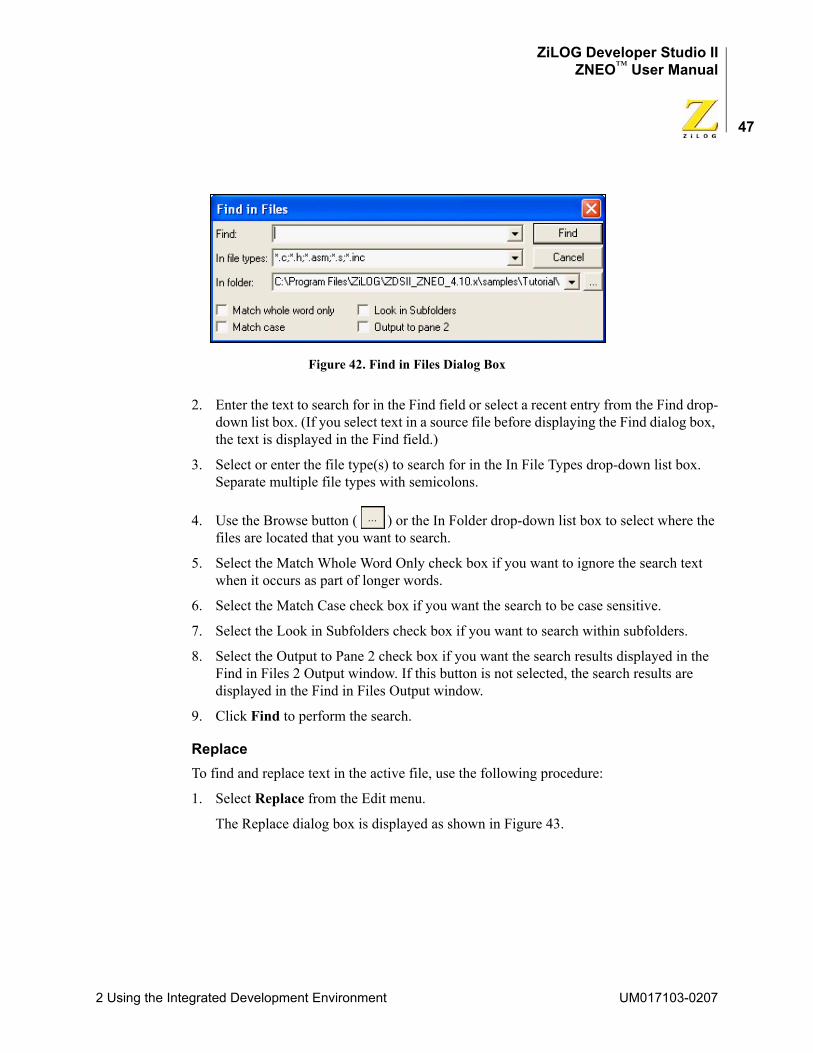
ZiLOG Developer Studio IIZNEO™ User Manual
47
Figure 42. Find in Files Dialog Box
2. Enter the text to search for in the Find field or select a recent entry from the Find drop-down list box. (If you select text in a source file before displaying the Find dialog box, the text is displayed in the Find field.)
3. Select or enter the file type(s) to search for in the In File Types drop-down list box. Separate multiple file types with semicolons.
4. Use the Browse button ( ) or the In Folder drop-down list box to select where the files are located that you want to search.
5. Select the Match Whole Word Only check box if you want to ignore the search text when it occurs as part of longer words.
6. Select the Match Case check box if you want the search to be case sensitive.
7. Select the Look in Subfolders check box if you want to search within subfolders.
8. Select the Output to Pane 2 check box if you want the search results displayed in the Find in Files 2 Output window. If this button is not selected, the search results are displayed in the Find in Files Output window.
9. Click Find to perform the search.
ReplaceTo find and replace text in the active file, use the following procedure:
1. Select Replace from the Edit menu.
The Replace dialog box is displayed as shown in Figure 43.
2 Using the Integrated Development Environment UM017103-0207
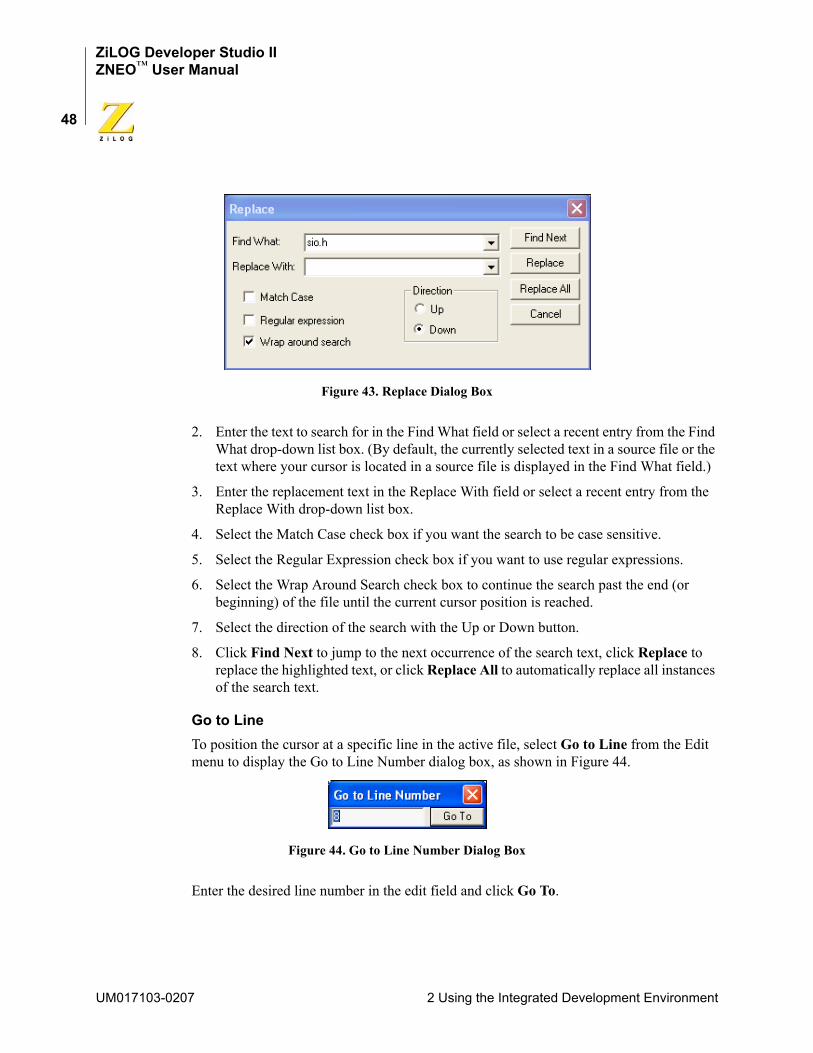
ZiLOG Developer Studio IIZNEO™ User Manual
48
Figure 43. Replace Dialog Box
2. Enter the text to search for in the Find What field or select a recent entry from the Find What drop-down list box. (By default, the currently selected text in a source file or the text where your cursor is located in a source file is displayed in the Find What field.)
3. Enter the replacement text in the Replace With field or select a recent entry from the Replace With drop-down list box.
4. Select the Match Case check box if you want the search to be case sensitive.
5. Select the Regular Expression check box if you want to use regular expressions.
6. Select the Wrap Around Search check box to continue the search past the end (or beginning) of the file until the current cursor position is reached.
7. Select the direction of the search with the Up or Down button.
8. Click Find Next to jump to the next occurrence of the search text, click Replace to replace the highlighted text, or click Replace All to automatically replace all instances of the search text.
Go to LineTo position the cursor at a specific line in the active file, select Go to Line from the Edit menu to display the Go to Line Number dialog box, as shown in Figure 44.
Figure 44. Go to Line Number Dialog Box
Enter the desired line number in the edit field and click Go To.
UM017103-0207 2 Using the Integrated Development Environment
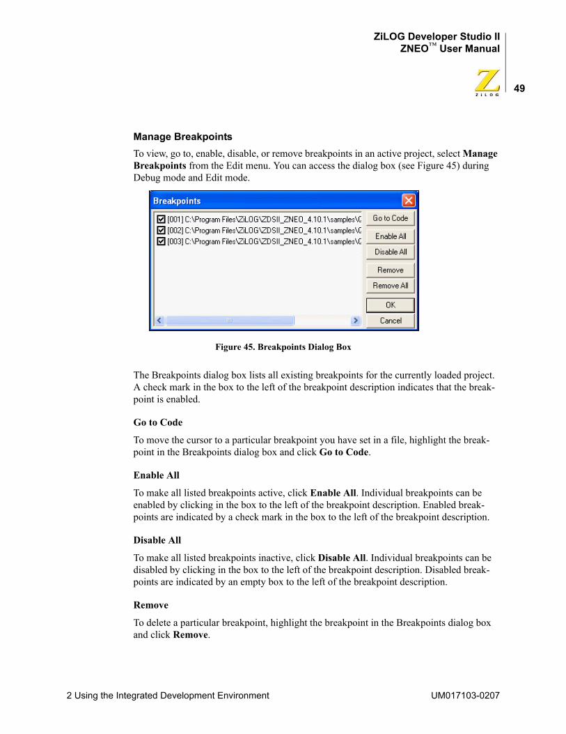
ZiLOG Developer Studio IIZNEO™ User Manual
49
Manage BreakpointsTo view, go to, enable, disable, or remove breakpoints in an active project, select Manage Breakpoints from the Edit menu. You can access the dialog box (see Figure 45) during Debug mode and Edit mode.
Figure 45. Breakpoints Dialog Box
The Breakpoints dialog box lists all existing breakpoints for the currently loaded project. A check mark in the box to the left of the breakpoint description indicates that the break-point is enabled.
Go to Code
To move the cursor to a particular breakpoint you have set in a file, highlight the break-point in the Breakpoints dialog box and click Go to Code.
Enable All
To make all listed breakpoints active, click Enable All. Individual breakpoints can be enabled by clicking in the box to the left of the breakpoint description. Enabled break-points are indicated by a check mark in the box to the left of the breakpoint description.
Disable All
To make all listed breakpoints inactive, click Disable All. Individual breakpoints can be disabled by clicking in the box to the left of the breakpoint description. Disabled break-points are indicated by an empty box to the left of the breakpoint description.
Remove
To delete a particular breakpoint, highlight the breakpoint in the Breakpoints dialog box and click Remove.
2 Using the Integrated Development Environment UM017103-0207
ZiLOG Developer Studio IIZNEO™ User Manual
50
Remove All
To delete all of the listed breakpoints, click Remove All.
NOTE: For more information on breakpoints, see “Using Breakpoints” on page 293.
Toggle BookmarkSelect Toggle Bookmark from the Edit menu to insert a bookmark in the active file for the line where your cursor is located or to remove the bookmark for the line where your cursor is located.
Next BookmarkSelect Next Bookmark from the Edit menu to position the cursor at the line where the next bookmark in the active file is located.
NOTE: The search for the next bookmark does not stop at the end of the file; the next bookmark might be the first bookmark in the file.
Previous BookmarkSelect Previous Bookmark from the Edit menu to position the cursor at the line where the previous bookmark in the active file is located.
NOTE: The search for the previous bookmark does not stop at the beginning of the file; the previous bookmark might be the last bookmark in the file.
Remove All BookmarksSelect Remove All Bookmarks from the Edit menu to delete all of the bookmarks in the currently loaded project.
View MenuThe View menu allows you to select the windows you want to display in the ZNEO devel-oper’s environment.
The View menu contains these options:
• “Debug Windows” on page 50
• “Workspace” on page 51
• “Output” on page 51
• “Status Bar” on page 51
Debug WindowsWhen you are in Debug mode (running the debugger), you can select any of the Debug windows. From the View menu, select Debug Windows and then the appropriate Debug window.
UM017103-0207 2 Using the Integrated Development Environment
ZiLOG Developer Studio IIZNEO™ User Manual
51
For more information on the Debug windows, see “Debug Windows” on page 279.
The Debug Windows submenu contains the following:
• “Registers Window” on page 279
• “Special Function Registers Window” on page 280
• “Clock Window” on page 281
• “Memory Window” on page 282
• “Watch Window” on page 287
• “Locals Window” on page 290
• “Call Stack Window” on page 290
• “Symbols Window” on page 291
• “Disassembly Window” on page 291
• “Simulated UART Output Window” on page 292
WorkspaceSelect Workspace from the View menu to display or hide the Project Workspace window.
OutputSelect Output from the View menu to display or hide the Output windows.
Status BarSelect Status Bar from the View menu to display or hide the status bar, which resides beneath the Build Output window.
Project MenuThe Project menu allows you to add files to your project, set configurations for your project, and export a make file.
The Project menu contains the following options:
• “Add Files” on page 52
• “Remove Selected File(s)” on page 52
• “Settings” on page 52
• “Export Makefile” on page 88
2 Using the Integrated Development Environment UM017103-0207
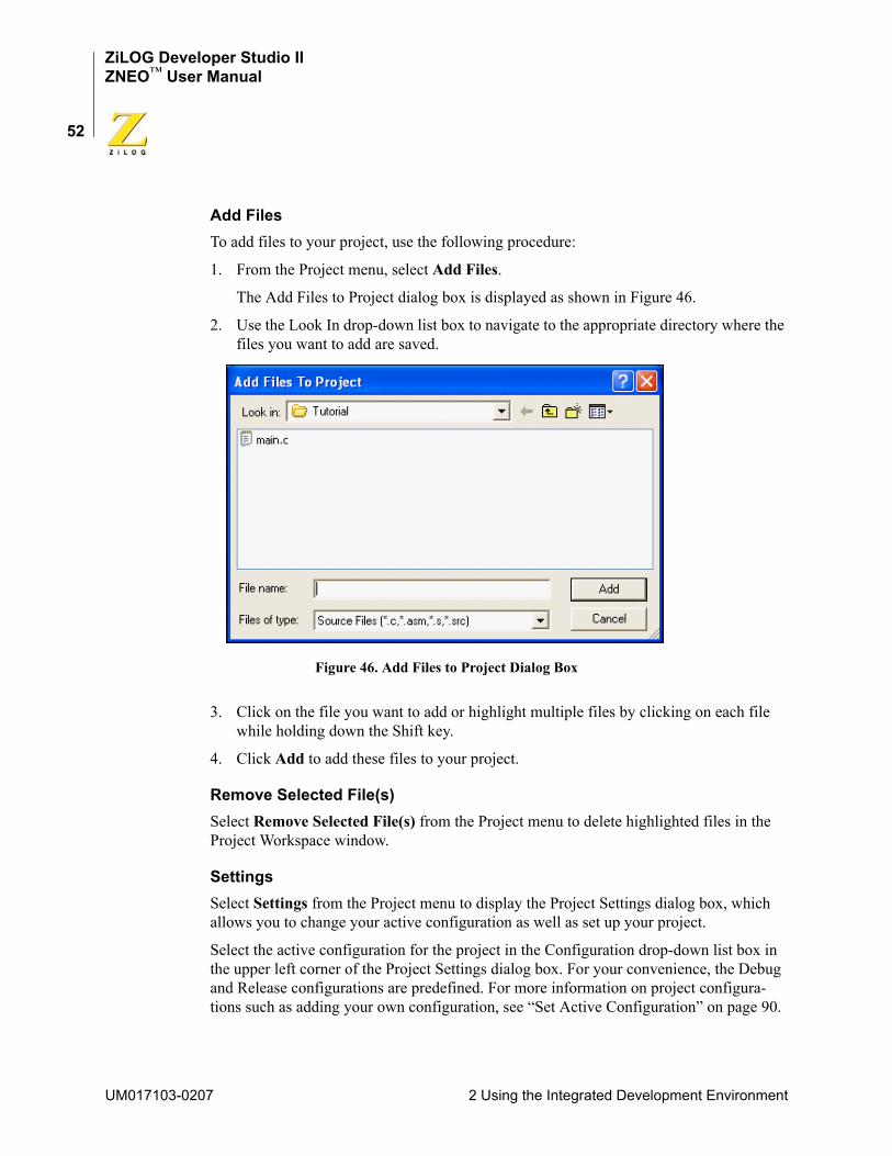
ZiLOG Developer Studio IIZNEO™ User Manual
52
Add FilesTo add files to your project, use the following procedure:
1. From the Project menu, select Add Files.
The Add Files to Project dialog box is displayed as shown in Figure 46.
2. Use the Look In drop-down list box to navigate to the appropriate directory where the files you want to add are saved.
Figure 46. Add Files to Project Dialog Box
3. Click on the file you want to add or highlight multiple files by clicking on each file while holding down the Shift key.
4. Click Add to add these files to your project.
Remove Selected File(s)Select Remove Selected File(s) from the Project menu to delete highlighted files in the Project Workspace window.
SettingsSelect Settings from the Project menu to display the Project Settings dialog box, which allows you to change your active configuration as well as set up your project.
Select the active configuration for the project in the Configuration drop-down list box in the upper left corner of the Project Settings dialog box. For your convenience, the Debug and Release configurations are predefined. For more information on project configura-tions such as adding your own configuration, see “Set Active Configuration” on page 90.
UM017103-0207 2 Using the Integrated Development Environment

ZiLOG Developer Studio IIZNEO™ User Manual
53
The Project Settings dialog box has different pages you must use to set up the project:
• “Project Settings—General Page” on page 54
• “Project Settings—Assembler Page” on page 56
• “Project Settings—Code Generation Page” on page 57 (not available for Assembly Only projects)
• “Project Settings—Listing Files Page” on page 59 (not available for Assembly Only projects)
• “Project Settings—Preprocessor Page” on page 61 (not available for Assembly Only projects)
• “Project Settings—Advanced Page” on page 62 (not available for Assembly Only projects)
• “Project Settings—Librarian Page” on page 66 (available for Static Library projects only)
• “Project Settings—Commands Page” on page 66 (available for Executable projects only)
• “Project Settings—Objects and Libraries Page” on page 70 (available for Executable projects only)
• “Project Settings—Address Spaces Page” on page 74 (available for Executable projects only)
• “Project Settings—Warnings Page” on page 77 (available for Executable projects only)
• “Project Settings—Output Page” on page 78 (available for Executable projects only)
• “Project Settings—Debugger Page” on page 81 (available for Executable projects only)
The Project Settings dialog box provides various project configuration pages that can be accessed by selecting the page name in the pane on the left side of the dialog box. There are several pages grouped together for the C (Compiler) and Linker that allow you to set up subsettings for that tool. The pages for the C (Compiler) are Code Generation, Listing Files, Preprocessor, and Advanced. The pages for the Linker are Commands, Objects and Libraries, Address Spaces, Warnings, and Output.
NOTE: If you change project settings that affect the build, the following message is displayed when you click OK to exit the Project Settings dialog box: “The project settings have changed since the last build. Would you like to rebuild the affected files?” Click Yes to save and then rebuild the project.
2 Using the Integrated Development Environment UM017103-0207
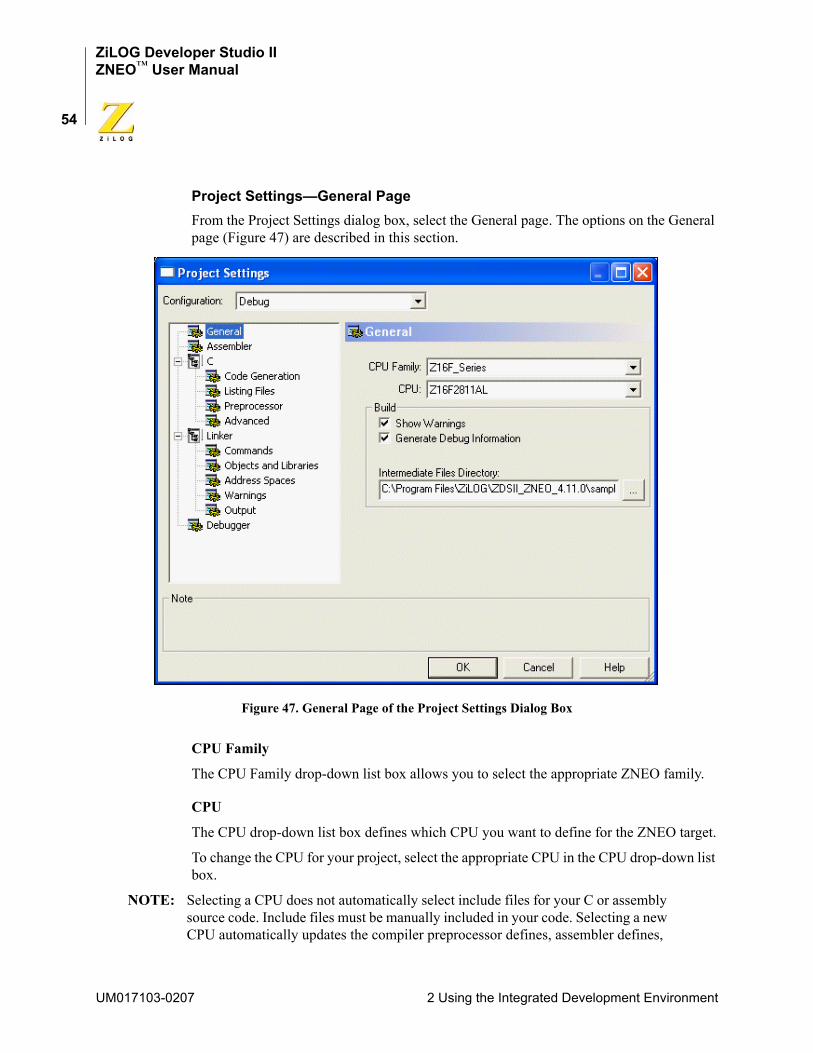
ZiLOG Developer Studio IIZNEO™ User Manual
54
Project Settings—General PageFrom the Project Settings dialog box, select the General page. The options on the General page (Figure 47) are described in this section.
Figure 47. General Page of the Project Settings Dialog Box
CPU Family
The CPU Family drop-down list box allows you to select the appropriate ZNEO family.
CPU
The CPU drop-down list box defines which CPU you want to define for the ZNEO target.
To change the CPU for your project, select the appropriate CPU in the CPU drop-down list box.
NOTE: Selecting a CPU does not automatically select include files for your C or assembly source code. Include files must be manually included in your code. Selecting a new CPU automatically updates the compiler preprocessor defines, assembler defines,
UM017103-0207 2 Using the Integrated Development Environment
ZiLOG Developer Studio IIZNEO™ User Manual
55
and, where necessary, the linker address space ranges and selected debugger target based on the selected CPU.
Show Warnings
The Show Warnings check box controls the display of warning messages during all phases of the build. If the check box is enabled, warning messages from the assembler, compiler, librarian, and linker are displayed during the build. If the check box is disabled, all these warnings are suppressed.
Generate Debug Information
The Generate Debug Information check box makes the build generate debug information that can be used by the debugger to allow symbolic debugging. Enable this option if you are planning to debug your code using the debugger. The check box enables debug infor-mation in the assembler, compiler, and linker.
Enabling this option usually increases your overall code size by a moderate amount for two reasons. First, if your code makes any calls to the C run-time libraries, the library ver-sion used is the one that was built using the Limit Optimizations for Easier Debugging set-ting (see the “Limit Optimizations for Easier Debugging” on page 58). Second, the generated code sets up the stack frame for every function in your own program. Many functions (those whose parameters and local variables are not too numerous and do not have their addresses taken in your code) would not otherwise require a stack frame in the ZNEO architecture, so the code for these functions is slightly smaller if this check box is disabled.
NOTE: This check box interacts with the Limit Optimizations for Easier Debugging check box on the Code Generation page (see “Limit Optimizations for Easier Debugging” on page 58). When the Limit Optimizations for Easier Debugging check box is selected, debug information is always generated so that debugging can be performed. The Generate Debug Information check box is grayed out (disabled) when the Limit Optimizations for Easier Debugging check box is selected. If the Limit Optimizations for Easier Debugging check box is later deselected (even in a later ZDS II session), the Generate Debug Information check box returns to the setting it had before the Limit Optimizations for Easier Debugging check box was selected.
Ignore Case of Symbols
When the Ignore Case of Symbols check box is enabled, the assembler and linker ignore the case of symbols when generating and linking code. This check box is occasionally needed when a project contains source files with case-insensitive labels. This check box is only available for Assembly Only projects with no C code.
2 Using the Integrated Development Environment UM017103-0207
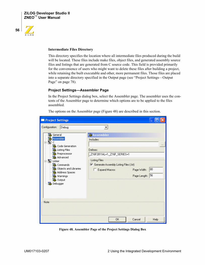
ZiLOG Developer Studio IIZNEO™ User Manual
56
Intermediate Files Directory
This directory specifies the location where all intermediate files produced during the build will be located. These files include make files, object files, and generated assembly source files and listings that are generated from C source code. This field is provided primarily for the convenience of users who might want to delete these files after building a project, while retaining the built executable and other, more permanent files. Those files are placed into a separate directory specified in the Output page (see “Project Settings—Output Page” on page 78).
Project Settings—Assembler PageIn the Project Settings dialog box, select the Assembler page. The assembler uses the con-tents of the Assembler page to determine which options are to be applied to the files assembled.
The options on the Assembler page (Figure 48) are described in this section.
Figure 48. Assembler Page of the Project Settings Dialog Box
UM017103-0207 2 Using the Integrated Development Environment
ZiLOG Developer Studio IIZNEO™ User Manual
57
Includes
The Includes field allows you to specify the series of paths for the assembler to use when searching for include files. The assembler first checks the current directory, then the paths in the Includes field, and finally the default ZDS II include directories.
The ZDS II default include directory is<ZDS Installation Directory>\include\std
where <ZDS Installation Directory> is the directory in which ZiLOG Developer Studio was installed. By default, this would be C:\Program Files\ZiLOG\ZDSII_ZNEO_<version>, where <version> might be 4.11.0 or 5.0.0.
Defines
The Defines field is equivalent to placing <symbol> EQU <value> in your assembly source code. It is useful for conditionally built code. Each defined symbol must have a corresponding value (<name>=<value>). Multiple symbols can be defined and must be separated by commas.
Generate Assembly Listing Files (.lst)
When selected, the Generate Assembly Listing Files (.lst) check box tells the assembler to create an assembly listing file for each assembly source code module. This file displays the assembly code and directives, as well as the hexadecimal addresses and op codes of the generated machine code. The assembly listing files are saved in the directory specified by the Intermediate Files Directory field on the General page (see “Intermediate Files Directory” on page 56). By default, this check box is selected.
Expand Macros
When selected, the Expand Macros check box tells the assembler to expand macros in the assembly listing files.
Page Length
When the assembler generates the listing files, the Page Length field sets the maximum number of lines between page breaks. The default is 56.
Page Width
When the assembler generates the listing files, the Page Width field sets the maximum number of characters on a line. The default is 80; the maximum width is 132.
Project Settings—Code Generation PageNOTE: For Assembly Only projects, the Code Generation page is not available.
2 Using the Integrated Development Environment UM017103-0207
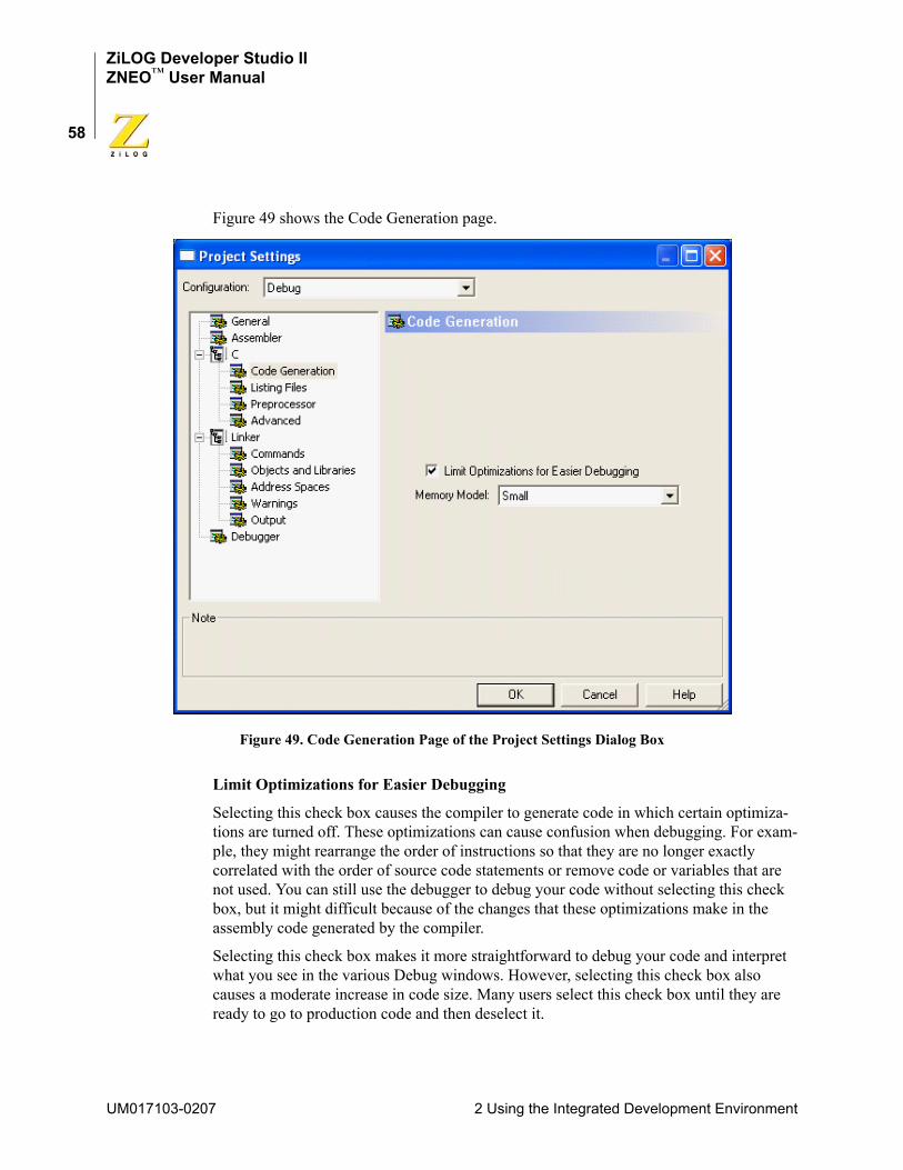
ZiLOG Developer Studio IIZNEO™ User Manual
58
Figure 49 shows the Code Generation page.
Figure 49. Code Generation Page of the Project Settings Dialog Box
Limit Optimizations for Easier Debugging
Selecting this check box causes the compiler to generate code in which certain optimiza-tions are turned off. These optimizations can cause confusion when debugging. For exam-ple, they might rearrange the order of instructions so that they are no longer exactly correlated with the order of source code statements or remove code or variables that are not used. You can still use the debugger to debug your code without selecting this check box, but it might difficult because of the changes that these optimizations make in the assembly code generated by the compiler.
Selecting this check box makes it more straightforward to debug your code and interpret what you see in the various Debug windows. However, selecting this check box also causes a moderate increase in code size. Many users select this check box until they are ready to go to production code and then deselect it.
UM017103-0207 2 Using the Integrated Development Environment

ZiLOG Developer Studio IIZNEO™ User Manual
59
Selecting this check box can also increase the data size required by your application. This happens because this option turns off the use of register variables (see “Use Register Vari-ables” on page 63). The variables that are no longer stored in registers must instead be stored in memory (and on the stack if dynamic frames are in use), thereby increasing the overall data storage requirements of your application. Usually this increase is fairly small.
You can debug your application when this check box is deselected. The debugger contin-ues to function normally, but debugging might be more confusing due to the factors described earlier.
NOTE: This check box interacts with the Generate Debug Information check box (see “Generate Debug Information” on page 55).
Memory Model
The Memory Model drop-down list allows you to choose between the two memory mod-els supported by the ZNEO C-Compiler, Small or Large. One fundamental difference between these models is that the small model can be implemented using only ZNEO CPU’s internal Flash and RAM memory, but the large model requires the presence of external RAM. Using the small model also results in more compact code and often reduces the RAM requirements as well. However, the small model places constraints on the data space size (not on the code space size) of your application. Some applications might not be able to fit into the small model’s data space size; the large model is provided to support such applications. See “Memory Models” on page 119 for full details of the memory models.
Project Settings—Listing Files PageNOTE: For Assembly Only projects, the Listing Files page is not available.
Figure 50 shows the Listing Files page.
2 Using the Integrated Development Environment UM017103-0207
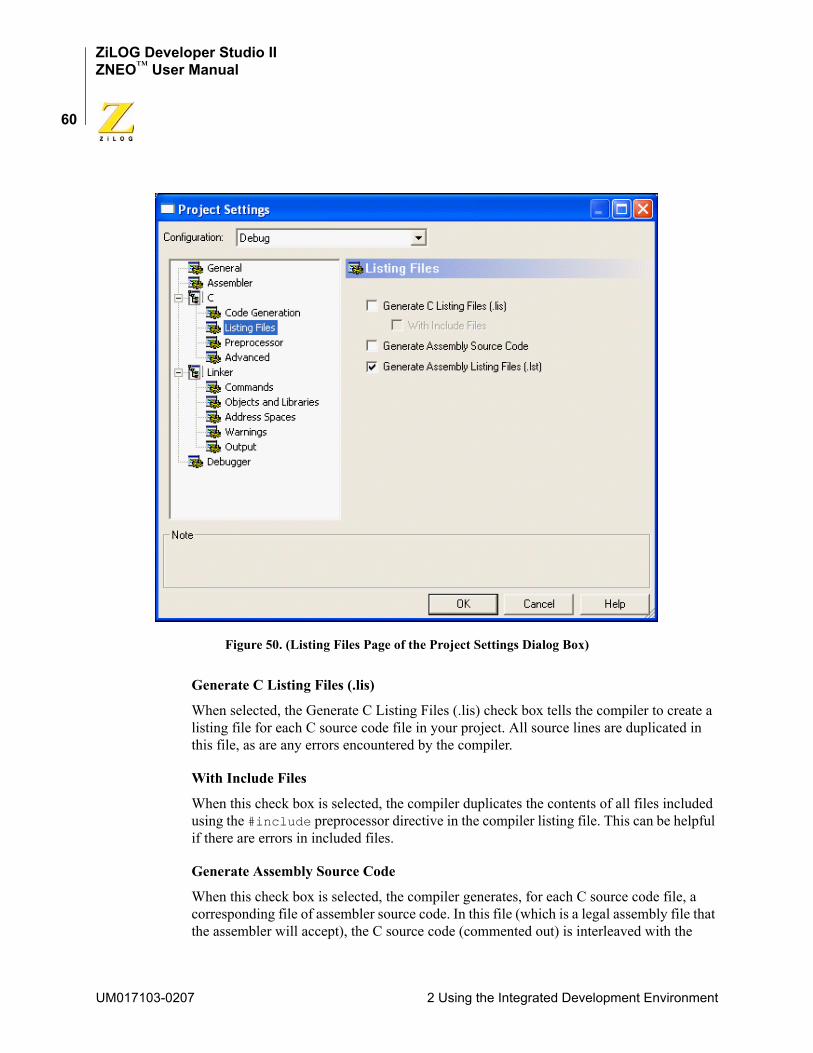
ZiLOG Developer Studio IIZNEO™ User Manual
60
Figure 50. (Listing Files Page of the Project Settings Dialog Box)
Generate C Listing Files (.lis)
When selected, the Generate C Listing Files (.lis) check box tells the compiler to create a listing file for each C source code file in your project. All source lines are duplicated in this file, as are any errors encountered by the compiler.
With Include Files
When this check box is selected, the compiler duplicates the contents of all files included using the #include preprocessor directive in the compiler listing file. This can be helpful if there are errors in included files.
Generate Assembly Source Code
When this check box is selected, the compiler generates, for each C source code file, a corresponding file of assembler source code. In this file (which is a legal assembly file that the assembler will accept), the C source code (commented out) is interleaved with the
UM017103-0207 2 Using the Integrated Development Environment

ZiLOG Developer Studio IIZNEO™ User Manual
61
generated assembly code and the compiler-generated assembly directives. This file is placed in the directory specified by the Intermediate Files Directory check box in the Gen-eral page. See “Intermediate Files Directory” on page 56.
Generate Assembly Listing Files (.lst)
When this check box is selected, the compiler generates, for each C source code file, a cor-responding assembly listing file. In this file, the C source code is displayed, interleaved with the generated assembly code and the compiler-generated assembly directives. This file also displays the hexadecimal addresses and op codes of the generated machine code. This file is placed in the directory specified by the Intermediate Files Directory field in the General page. See “Intermediate Files Directory” on page 56.
Project Settings—Preprocessor PageNOTE: For Assembly Only projects, the Preprocessor page is not available.
Figure 51 shows the Preprocessor page.
Figure 51. Preprocessor Page of the Project Settings Dialog Box
2 Using the Integrated Development Environment UM017103-0207
ZiLOG Developer Studio IIZNEO™ User Manual
62
Preprocessor Definitions
The Preprocessor Definitions field is equivalent to placing #define preprocessor direc-tives before any lines of code in your program. It is useful for conditionally compiling code. Do not put a space between the symbol\name and equal sign; however, multiple symbols can be defined and must be separated by commas.
Standard Include Path
The Standard Include Path field allows you to specify the series of paths for the compiler to use when searching for standard include files. Standard include files are those included with the #include <file.h> preprocessor directive. If more than one path is used, the paths are separated by semicolons (;). The compiler first checks the current directory, then the paths in the Standard Include Path field. The default standard includes are located in the following directories:
<ZDS Installation Directory>\include\std <ZDS Installation Directory>\include\zilog
where <ZDS Installation Directory> is the directory in which ZiLOG Developer Studio was installed. By default, this would be C:\Program Files\ZiLOG\ZDSII_ZNEO_<version>, where <version> might be 4.11.0 or 5.0.0.
User Include Path
The User Include Path field allows you to specify the series of paths for the compiler to use when searching for user include files. User include files are those included with the #include "file.h" in the compiler. If more than one path is used, the paths are sepa-rated by semicolons (;). The compiler first checks the current directory, then the paths in the User Include Path field.
Project Settings—Advanced PageNOTE: For Assembly Only projects, the Advanced page is not available.
Figure 52 shows the Advanced page.
UM017103-0207 2 Using the Integrated Development Environment
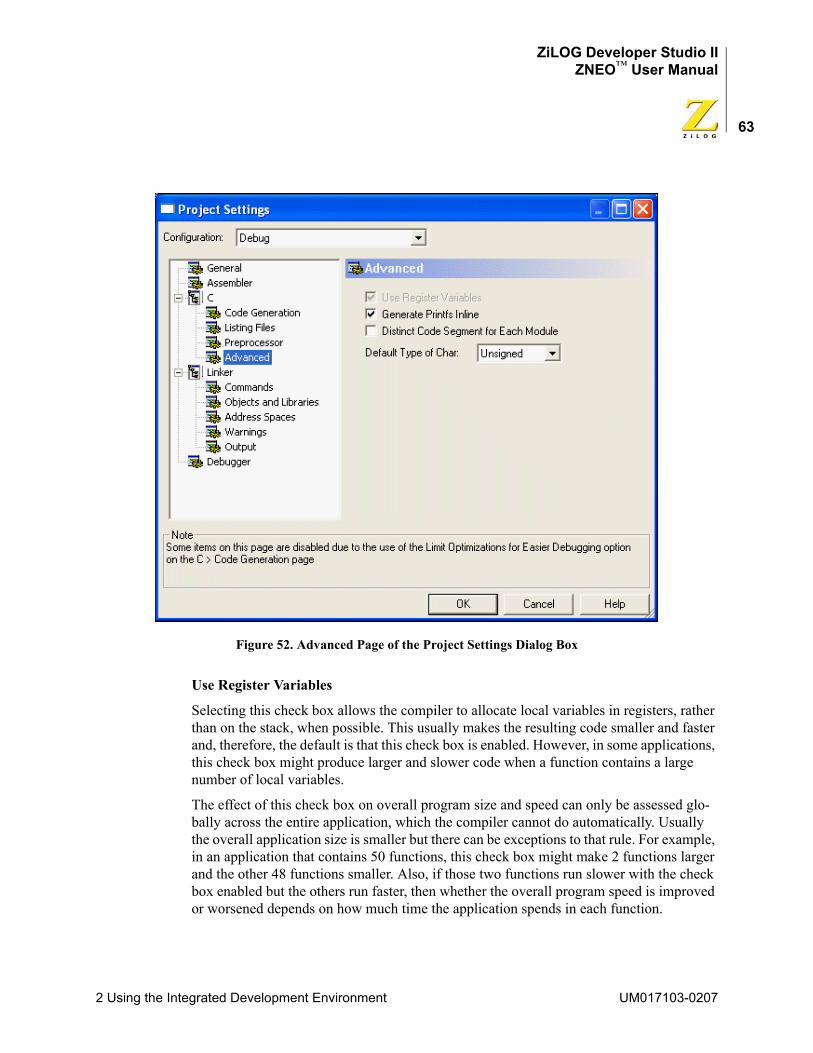
ZiLOG Developer Studio IIZNEO™ User Manual
63
Figure 52. Advanced Page of the Project Settings Dialog Box
Use Register Variables
Selecting this check box allows the compiler to allocate local variables in registers, rather than on the stack, when possible. This usually makes the resulting code smaller and faster and, therefore, the default is that this check box is enabled. However, in some applications, this check box might produce larger and slower code when a function contains a large number of local variables.
The effect of this check box on overall program size and speed can only be assessed glo-bally across the entire application, which the compiler cannot do automatically. Usually the overall application size is smaller but there can be exceptions to that rule. For example, in an application that contains 50 functions, this check box might make 2 functions larger and the other 48 functions smaller. Also, if those two functions run slower with the check box enabled but the others run faster, then whether the overall program speed is improved or worsened depends on how much time the application spends in each function.
2 Using the Integrated Development Environment UM017103-0207
ZiLOG Developer Studio IIZNEO™ User Manual
64
Because the effect of applying this option must be evaluated across an application as a whole, user experimentation is required to test this for an individual application. Only a small fraction of applications benefit from deselecting the Use Register Variables check box.
NOTE: This check box interacts with the Limit Optimizations for Easier Debugging check box on the C page (see “Limit Optimizations for Easier Debugging” on page 58). When the Limit Optimizations for Easier Debugging check box is selected, register variables are not used because they can cause confusion when debugging. The Use Register Variables check box is disabled (grayed out) when the Limit Optimizations for Easier Debugging check box is selected. If the Limit Optimizations for Easier Debugging check box is later deselected (even in a later ZDS II session), the Use Register Variables check box returns to the setting it had before the Limit Optimizations for Easier Debugging check box was selected. Using register variables can complicate debugging in at least two ways. One way is that register variables are more likely to be optimized away by the compiler. If variables you want to observe while debugging are being optimized away, you can usually prevent this by any of the following actions:
• Select the Limit Optimizations for Easier Debugging check box (see “Limit Optimizations for Easier Debugging” on page 58)
• Deselect the Use Register Variables check box
• Rewrite your code so that the variables in question become global rather than local
The other way that register variables can lead to confusing behavior when debugging is that the same register can be used for different variables or temporary results at different times in the execution of your code. Because the debugger is not always aware of these multiple uses, sometimes a value for a register variable might be shown in the Watch win-dow that is not actually related to that variable at all.
Generate Printfs Inline
Normally, a call to printf() or sprintf() parses the format string at run time to gener-ate the required output. When the Generate Printfs Inline check box is selected, the format string is parsed at compile time, and direct inline calls to the lower level helper functions are generated. This results in significantly smaller overall code size because the top-level routines to parse a format string are not linked into the project, and only those lower level routines that are actually used are linked in, rather than every routine that could be used by a call to printf. The code size of each routine that calls printf() or sprintf() is slightly larger than if the Generate Printfs inline check box is deselected, but this is more than offset by the significant reduction in the size of library functions that are linked to your application.
UM017103-0207 2 Using the Integrated Development Environment
ZiLOG Developer Studio IIZNEO™ User Manual
65
To reduce overall code size by selecting this check box, the following conditions are nec-essary:
• All calls to printf() and sprintf() must use string literals, rather than char* variables, as parameters. For example, the following code allows the compiler to reduce the code size:sprintf ("Timer will be reset in %d seconds", reset_time);
But code like the following results in larger code:char * timerWarningMessage; ... sprintf (timerWarningMessage, reset_time);
• The functions vprintf() and vsprintf() cannot be used, even if the format string is a string literal.
If the Generate Printfs Inline check box is selected and these conditions are not met, the compiler warns you that the code size cannot be reduced. In this case, the compiler gener-ates correct code, and the execution is significantly faster than with normal printf calls. However, there is a net increase in code size because the generated inline calls to lower level functions require more space with no compensating savings from removing the top-level functions.
In addition, an application that makes over 100 separate calls of printf or sprintf might result in larger code size with the Generate Printfs Inline check box selected because of the cumulative effect of all the inline calls. The compiler cannot warn about this situation. If in doubt, simply compile the application both ways and compare the resulting code sizes.
The Generate Printfs Inline check box is selected by default.
Distinct Code Segment for Each Module
For most applications, the code segment for each module compiled by the ZNEO compiler is named CODE. Later, in the linker step of the build process, the linker gathers all these small CODE segments into a single large CODE segment and then places that segment in the appropriate address space, thus ensuring that all the executable code is kept in a single contiguous block within a single address space. However, some users might need a more complex configuration in which particular code modules are put in different address spaces.
Such users can select the Distinct Code Segment for Each Module check box to accom-plish this purpose. When this check box is selected, the code segment for every module receives a distinct name; for example, the code segment generated for the myModule.c module is given the name myModule_TEXT. You can then add linker directives to the linker command file to place selected modules in the appropriate address spaces. This check box is deselected by default.
2 Using the Integrated Development Environment UM017103-0207

ZiLOG Developer Studio IIZNEO™ User Manual
66
An example of the use of this feature is to place most of the application’s code in the usual EROM address space (see “Project Settings—Address Spaces Page” on page 74 for a dis-cussion of the ZNEO address spaces) except for a particular module that is to be run from the RAM (16-bit addressable RAM) space. See “Special Case: Partial Download to RAM” on page 267 for an example of how to configure the linker command file for this type of application.
NOTE: It is the user’s responsibility to configure the linker command file properly when the Distinct Code Segment for Each Module check box is selected.
Default Type of Char
The ANSI C Standard permits the compiler to regard char variables that are not otherwise qualified as either signed or unsigned, at the compiler’s discretion; the compiler is only required to consistently apply the choice to all such variables. So in the following declara-tions:signed char sc;unsigned char uc;char cc;
the signedness of cc is left to the compiler. The Default Type of Char drop-down list box allows you to make this decision. The selection, Signed or Unsigned, is applied to all char variables whose signedness is not explicitly declared. The default value for ZNEO is Unsigned.
Project Settings—Librarian PageNOTE: This page is available for Static Library projects only.
To configure the librarian, use the following procedure:
1. Select Settings from the Project menu.
The Project Settings dialog box is displayed.
2. Click the Librarian page.
3. Use the Output File Name field to specify where your static library file is saved.
Project Settings—Commands PageFigure 56 shows the Commands page.
UM017103-0207 2 Using the Integrated Development Environment
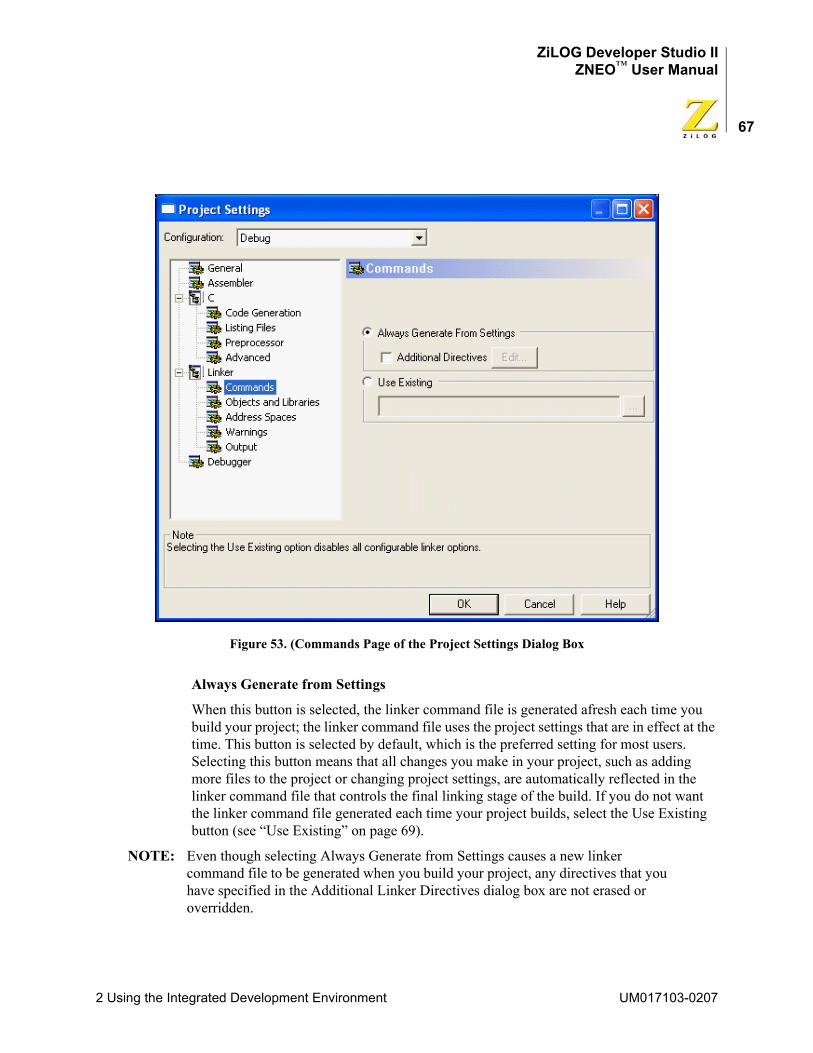
ZiLOG Developer Studio IIZNEO™ User Manual
67
Figure 53. (Commands Page of the Project Settings Dialog Box
Always Generate from Settings
When this button is selected, the linker command file is generated afresh each time you build your project; the linker command file uses the project settings that are in effect at the time. This button is selected by default, which is the preferred setting for most users. Selecting this button means that all changes you make in your project, such as adding more files to the project or changing project settings, are automatically reflected in the linker command file that controls the final linking stage of the build. If you do not want the linker command file generated each time your project builds, select the Use Existing button (see “Use Existing” on page 69).
NOTE: Even though selecting Always Generate from Settings causes a new linker command file to be generated when you build your project, any directives that you have specified in the Additional Linker Directives dialog box are not erased or overridden.
2 Using the Integrated Development Environment UM017103-0207
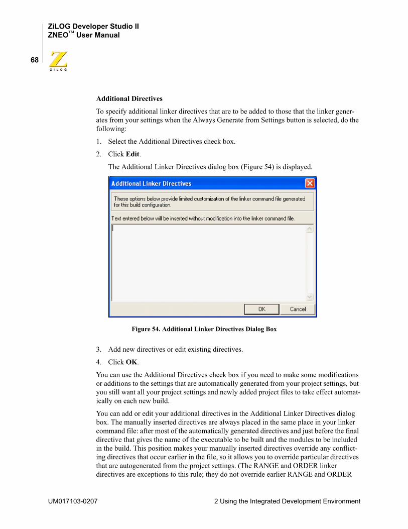
ZiLOG Developer Studio IIZNEO™ User Manual
68
Additional Directives
To specify additional linker directives that are to be added to those that the linker gener-ates from your settings when the Always Generate from Settings button is selected, do the following:
1. Select the Additional Directives check box.
2. Click Edit.
The Additional Linker Directives dialog box (Figure 54) is displayed.
Figure 54. Additional Linker Directives Dialog Box
3. Add new directives or edit existing directives.
4. Click OK.
You can use the Additional Directives check box if you need to make some modifications or additions to the settings that are automatically generated from your project settings, but you still want all your project settings and newly added project files to take effect automat-ically on each new build.
You can add or edit your additional directives in the Additional Linker Directives dialog box. The manually inserted directives are always placed in the same place in your linker command file: after most of the automatically generated directives and just before the final directive that gives the name of the executable to be built and the modules to be included in the build. This position makes your manually inserted directives override any conflict-ing directives that occur earlier in the file, so it allows you to override particular directives that are autogenerated from the project settings. (The RANGE and ORDER linker directives are exceptions to this rule; they do not override earlier RANGE and ORDER
UM017103-0207 2 Using the Integrated Development Environment
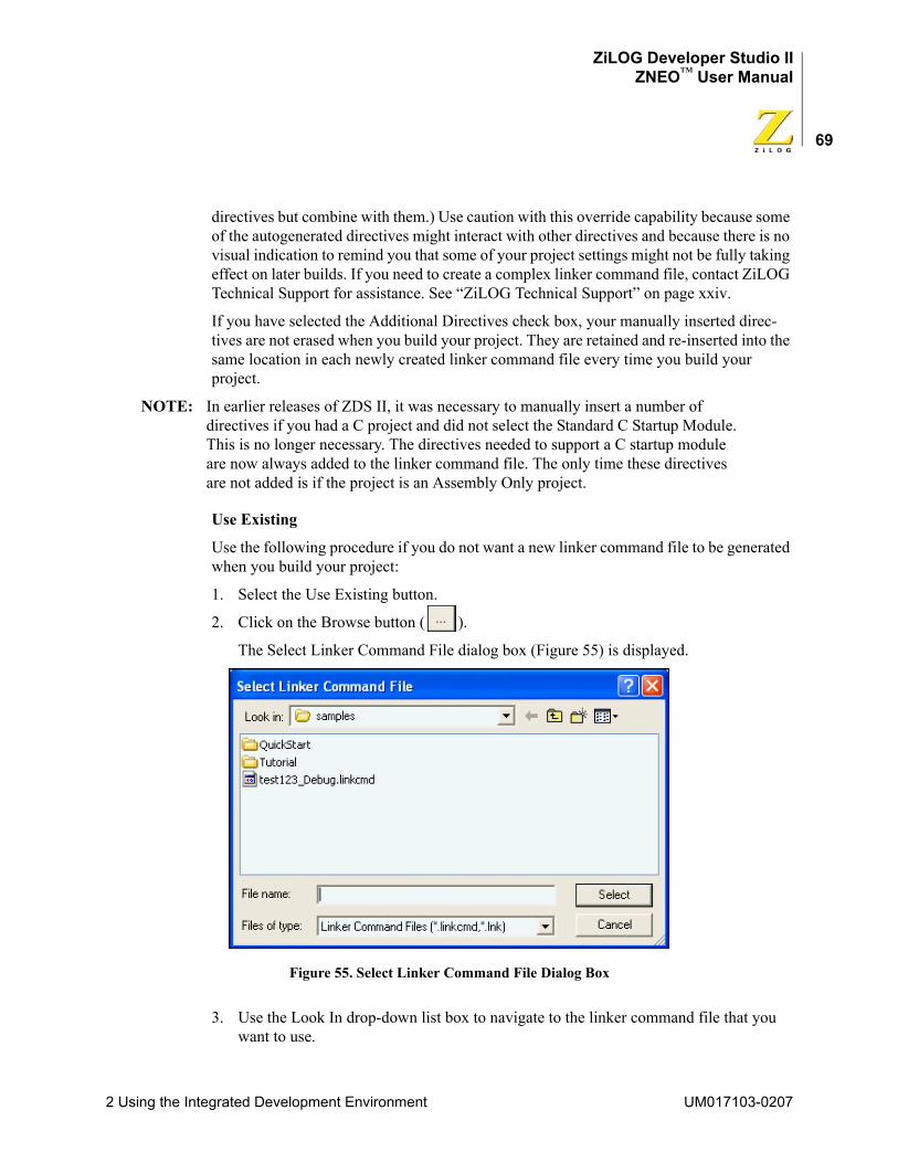
ZiLOG Developer Studio IIZNEO™ User Manual
69
directives but combine with them.) Use caution with this override capability because some of the autogenerated directives might interact with other directives and because there is no visual indication to remind you that some of your project settings might not be fully taking effect on later builds. If you need to create a complex linker command file, contact ZiLOG Technical Support for assistance. See “ZiLOG Technical Support” on page xxiv.
If you have selected the Additional Directives check box, your manually inserted direc-tives are not erased when you build your project. They are retained and re-inserted into the same location in each newly created linker command file every time you build your project.
NOTE: In earlier releases of ZDS II, it was necessary to manually insert a number of directives if you had a C project and did not select the Standard C Startup Module. This is no longer necessary. The directives needed to support a C startup module are now always added to the linker command file. The only time these directives are not added is if the project is an Assembly Only project.
Use Existing
Use the following procedure if you do not want a new linker command file to be generated when you build your project:
1. Select the Use Existing button.
2. Click on the Browse button ( ).
The Select Linker Command File dialog box (Figure 55) is displayed.
Figure 55. Select Linker Command File Dialog Box
3. Use the Look In drop-down list box to navigate to the linker command file that you want to use.
2 Using the Integrated Development Environment UM017103-0207

ZiLOG Developer Studio IIZNEO™ User Manual
70
4. Click Select.
The Use Existing button is the alternative to the Always Generate from Settings button (see “Always Generate from Settings” on page 67). When this button is selected, a new linker command file is not generated when you build your project. Instead, the linker com-mand file that you specify in this field is applied every time.
When the Use Existing button is selected, many project settings are grayed out, including all the settings on the Objects and Libraries page, Warnings page, and Output page. These settings are disabled because when you have specified that an existing linker command file is to be used, those settings have no effect.
NOTE: When the Use Existing button is selected, some other changes that you make in your project such as adding new files to the project also do not automatically take effect. To add new files to the project, you must not only add them to the Project Workspace window (see “Project Workspace Window” on page 26), but you must also edit your linker command file to add the corresponding object modules to the list of linked modules at the end of the linker command file.
Project Settings—Objects and Libraries PageFigure 56 shows the Objects and Libraries page.
UM017103-0207 2 Using the Integrated Development Environment
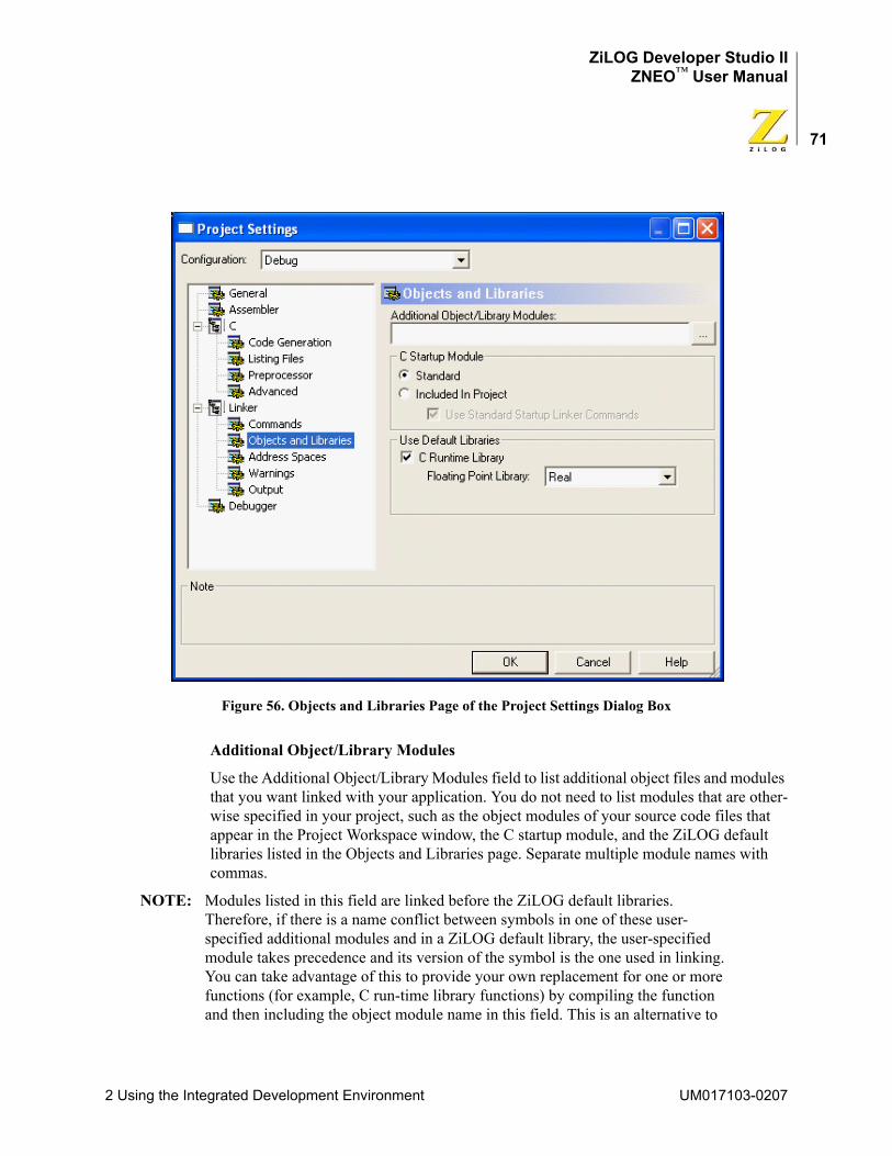
ZiLOG Developer Studio IIZNEO™ User Manual
71
Figure 56. Objects and Libraries Page of the Project Settings Dialog Box
Additional Object/Library Modules
Use the Additional Object/Library Modules field to list additional object files and modules that you want linked with your application. You do not need to list modules that are other-wise specified in your project, such as the object modules of your source code files that appear in the Project Workspace window, the C startup module, and the ZiLOG default libraries listed in the Objects and Libraries page. Separate multiple module names with commas.
NOTE: Modules listed in this field are linked before the ZiLOG default libraries. Therefore, if there is a name conflict between symbols in one of these user-specified additional modules and in a ZiLOG default library, the user-specified module takes precedence and its version of the symbol is the one used in linking. You can take advantage of this to provide your own replacement for one or more functions (for example, C run-time library functions) by compiling the function and then including the object module name in this field. This is an alternative to
2 Using the Integrated Development Environment UM017103-0207
ZiLOG Developer Studio IIZNEO™ User Manual
72
including the source code for the revised function explicitly in your project, which would also override the function in the default run-time library.
C Startup Module
The buttons and check box in this area (which are not available for Assembly Only projects) control which startup module is linked to your application. All C programs require some initialization before the main function is called, which is typically done in a startup module.
Standard
If the Standard button is selected, the precompiled startup module shipped with ZDS II is used. This standard startup module performs a minimum amount of initialization to pre-pare the run-time environment as required by the ANSI C Standard and also does some ZNEO-specific configuration such as interrupt vector table initialization. See “Language Extensions” on page 114 for full details of the operations performed in the standard startup module.
Some of these steps carried out in the standard startup module might not be required for every application, so if code space is extremely tight, you might want to make some judi-cious modifications to the startup code. The source code for the startup module is located in the following file:
<ZDS Installation Directory>\src\boot\common\startupX.asm
Here, <ZDS Installation Directory> is the directory in which ZiLOG Developer Studio was installed. By default, this is C:\Program Files\ZiLOG\ZDSII_ZNEO_<ver-sion>, where <version> might be 4.11.0 or 5.0.0. The X in startupX.asm is s for the small model or l for the large model.
Included in Project
If the Included in Project button is selected, then the standard startup module is not linked to your application. In this case, you are responsible for including suitable startup code, either by including the source code in the Project Workspace window or by including a precompiled object module in the Additional Object/Library Modules field. If you modify the standard startup module to tailor it to your project, you need to select the Included in Project button for your changes to take effect.
Use Standard Startup Linker Commands
If you select this check box, the same linker commands that support the standard startup module are inserted into your linker command file, even though you have chosen to include your own, nonstandard startup module in the project. This option is usually helpful in getting your project properly configured and initialized because all C startup modules have to do most of the same tasks. Formerly, these linker commands had to be inserted manually when you were not using the standard startup.
UM017103-0207 2 Using the Integrated Development Environment
ZiLOG Developer Studio IIZNEO™ User Manual
73
The standard startup commands define a number of linker symbols that are used in the standard startup module for initializing the C run-time environment. You do not have to refer to those symbols in your own startup module, but many users will find it useful to do so, especially since user-customized startup modules are often derived from modifying the standard startup module. There are also a few linker commands (such as CHANGE, COPY, ORDER, and GROUP) that are used to configure your memory map. See “Linker Com-mands” on page 215 for a description of these commands.
This option is only available when the Included in Project button has been selected. The default for newly created projects is that this check box, if available, is selected.
Use Default Libraries
These controls determine whether the available default libraries that are shipped with ZiLOG Developer Studio II are to be linked with your application. For ZNEO, there is essentially one available library, the C run-time library. The subset of the run-time library dedicated to floating-point operations also has a separate control to allow for special han-dling, as explained in “Floating Point Library” on page 73.
Use C Runtime Library
The C run-time library included with ZDS II provides selected functions and macros from the Standard C Library. ZiLOG’s version of the C run-time library supports a subset of the Standard Library adapted for embedded applications, as described more fully in the “Using the ANSI C-Compiler” chapter on page 113. If your project makes any calls to standard library functions, you need to select the Use C Runtime Library check box unless you prefer to provide your own code for all library functions that you call. As noted in “Additional Object/Library Modules” on page 71, you can also set up your application to call a mixture of ZiLOG-provided functions and your own customized library functions. To do so, select the Use C Runtime Library check box. Calls to standard library functions will then call the functions in the ZiLOG default library except when your own custom-ized versions exist.
ZiLOG’s version of the C run-time library is organized with a separate module for each function or, in a few cases, for a few closely related functions. Therefore, the linker links only those functions that you actually call in your code. This means that there is no unnec-essary code size penalty when you select the Use C Runtime Library check box; only functions you call in your application are linked into your application.
Floating Point Library
The Floating Point Library drop-down list box allows you to choose which version of the subset of the C run-time library that deals with the floating-point operations will be linked to your application:
• Real
2 Using the Integrated Development Environment UM017103-0207
ZiLOG Developer Studio IIZNEO™ User Manual
74
If you select Real, the true floating-point functions are linked in, and you can perform any floating-point operations you want in your code.
• Dummy
If you select Dummy, your application is linked with alternate versions that are stubbed out and do not actually carry out any floating-point operations. This dummy floating-point library has been developed to reduce code bloat caused by including calls to printf() and related functions such as sprintf(). Those functions in turn make calls to floating-point functions for help with formatting floating-point expressions, but those calls are unnecessary unless you actually need to format floating-point values. For most users, this problem has now been resolved by the Generate Printfs Inline check box (see “Generate Printfs Inline” on page 64 for a full discussion). You only need to select the dummy floating-point library if you have to disable the Generate Printfs Inline check box and your application uses no floating-point operations. In that case, selecting Dummy keeps your code size from bloating unnecessarily.
• None
If you can select None, no floating-point functions are linked to your application at all. This can be a way of ensuring that your code does not inadvertently make any floating-point calls, because, if it does and this option is selected, you receive a warning message about an undefined symbol.
NOTE: None of the libraries mentioned here are available for Assembly Only projects.
Project Settings—Address Spaces PageFigure 57 shows the Address Spaces page.
UM017103-0207 2 Using the Integrated Development Environment
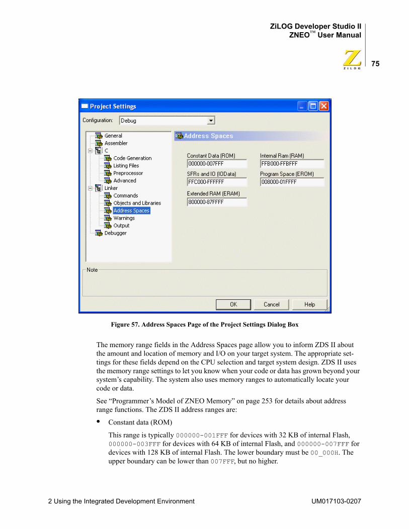
ZiLOG Developer Studio IIZNEO™ User Manual
75
Figure 57. Address Spaces Page of the Project Settings Dialog Box
The memory range fields in the Address Spaces page allow you to inform ZDS II about the amount and location of memory and I/O on your target system. The appropriate set-tings for these fields depend on the CPU selection and target system design. ZDS II uses the memory range settings to let you know when your code or data has grown beyond your system’s capability. The system also uses memory ranges to automatically locate your code or data.
See “Programmer’s Model of ZNEO Memory” on page 253 for details about address range functions. The ZDS II address ranges are:
• Constant data (ROM)
This range is typically 000000-001FFF for devices with 32 KB of internal Flash, 000000-003FFF for devices with 64 KB of internal Flash, and 000000-007FFF for devices with 128 KB of internal Flash. The lower boundary must be 00_000H. The upper boundary can be lower than 007FFF, but no higher.
2 Using the Integrated Development Environment UM017103-0207
ZiLOG Developer Studio IIZNEO™ User Manual
76
• Program space (EROM)
This range is typically 002000-007FFF for devices with 32 KB of internal Flash, 004000-00FFFF for devices with 64 KB of internal Flash, or 008000-01FFFF for devices with 128 KB of internal Flash. Specify a larger range only if the target system provides external nonvolatile memory.
NOTE: To use any external memory provided on the target system, you must configure the memory’s chip select in the Configure Target dialog box. See “Project Settings—Debugger Page” on page 81
• Extended RAM (ERAM)
Specify an ERAM range only if the target system provides external random access memory below FF8000. The ERAM field does not accept a starting address below 800000.
• Internal RAM (RAM)
This range is typically FFB700-FFBFFF for devices with 2 KB of internal RAM or FFB000-FFBFFF for devices with 4 KB of internal RAM. Despite its name, this range can be expanded up to FF8000-FFBFFF if the target system provides external random access memory to fill out this address range. This field does not allow a high RAM address boundary above FFBFFF.
• Special Function Registers and IO (IODATA)
Typically FFC000-FFFFFF. The microcontroller reserves addresses FFE000 and above for its special function registers, on-chip peripherals, and I/O ports. The ZDS II GUI expects addresses FFC000 to FFDFFF to be used for external I/O (if any) on the target system.
Address range settings must not overlap. The following is the syntax used in the address range fields:
<low address> – <high address> [,<low address> – <high address>] ...
where <low address> is the hexadecimal lower boundary of a range and <high address> is the hexadecimal higher boundary of the range. The following are legal memory ranges:0000-7fffffb000-ffbfff008000-01ffff,050000-07ffff
The last example line shows how a comma is used to define “holes” in a memory range for the linker. The linker does not place any code or data outside of the ranges specified here. If your code or data cannot be placed within the ranges, a range error is generated.
The C-Compiler does not support gaps (holes) within the ERAM or RAM ranges.
UM017103-0207 2 Using the Integrated Development Environment
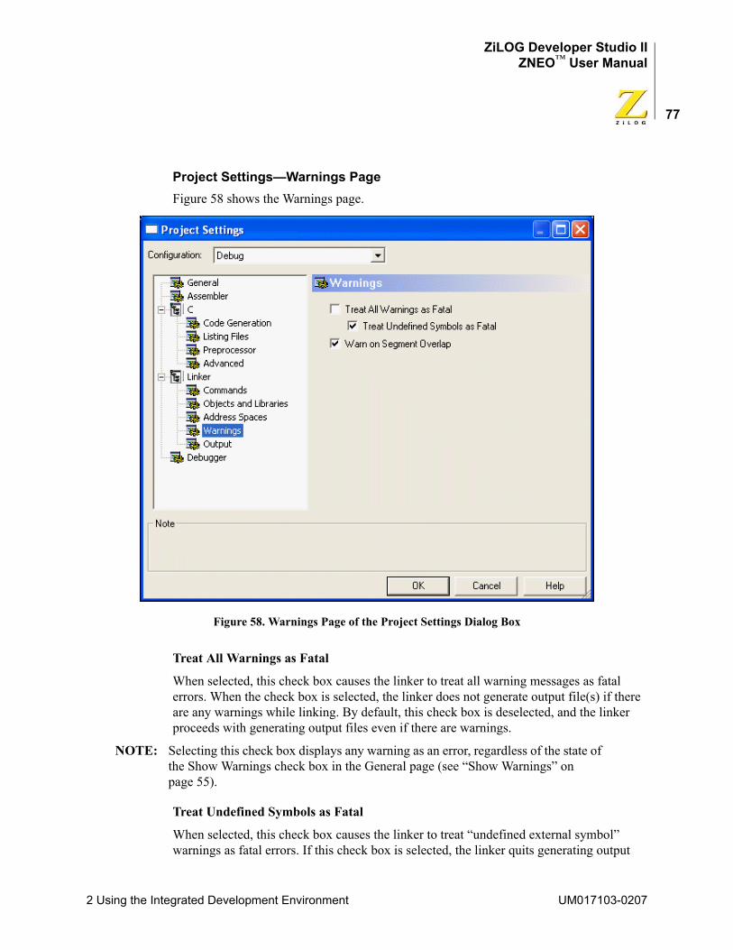
ZiLOG Developer Studio IIZNEO™ User Manual
77
Project Settings—Warnings PageFigure 58 shows the Warnings page.
Figure 58. Warnings Page of the Project Settings Dialog Box
Treat All Warnings as Fatal
When selected, this check box causes the linker to treat all warning messages as fatal errors. When the check box is selected, the linker does not generate output file(s) if there are any warnings while linking. By default, this check box is deselected, and the linker proceeds with generating output files even if there are warnings.
NOTE: Selecting this check box displays any warning as an error, regardless of the state of the Show Warnings check box in the General page (see “Show Warnings” on page 55).
Treat Undefined Symbols as Fatal
When selected, this check box causes the linker to treat “undefined external symbol” warnings as fatal errors. If this check box is selected, the linker quits generating output
2 Using the Integrated Development Environment UM017103-0207
ZiLOG Developer Studio IIZNEO™ User Manual
78
files and terminates with an error message immediately if the linker cannot resolve any undefined symbol. By default, this check box is selected because a completely valid exe-cutable cannot be built when the program contains references to undefined external sym-bols. If this check box is deselected, the linker proceeds with generating output files even if there are undefined symbols.
NOTE: Selecting this check box displays any “undefined external symbol” warning as an error, regardless of the state of the Show Warnings check box in the General page (see “Show Warnings” on page 55).
Warn on Segment Overlap
This check box enables or disables warnings when overlap occurs while binding seg-ments. By default, the check box is selected, which is the recommended setting for ZNEO. For some ZiLOG processors, benign segment overlaps can occur, but, for the ZNEO, an overlap condition usually indicates an error in project configuration that must be cor-rected. These errors in ZNEO can be caused either by user assembly code that erroneously assigns two or more segments to overlapping address ranges or by user code defining the same interrupt vector segment in two or more places.
Project Settings—Output PageFigure 59 shows the Output page.
UM017103-0207 2 Using the Integrated Development Environment
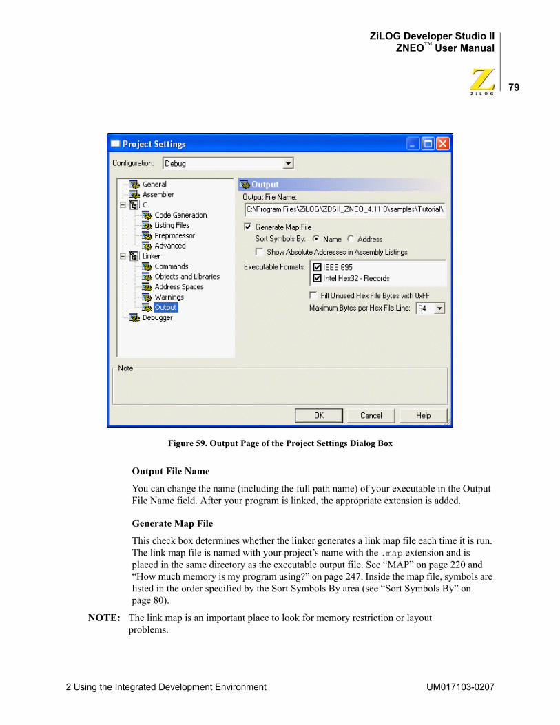
ZiLOG Developer Studio IIZNEO™ User Manual
79
Figure 59. Output Page of the Project Settings Dialog Box
Output File Name
You can change the name (including the full path name) of your executable in the Output File Name field. After your program is linked, the appropriate extension is added.
Generate Map File
This check box determines whether the linker generates a link map file each time it is run. The link map file is named with your project’s name with the .map extension and is placed in the same directory as the executable output file. See “MAP” on page 220 and “How much memory is my program using?” on page 247. Inside the map file, symbols are listed in the order specified by the Sort Symbols By area (see “Sort Symbols By” on page 80).
NOTE: The link map is an important place to look for memory restriction or layout problems.
2 Using the Integrated Development Environment UM017103-0207
ZiLOG Developer Studio IIZNEO™ User Manual
80
Sort Symbols By
You can choose whether to have symbols in the link map file sorted by name or address.
Show Absolute Addresses in Assembly Listings
When this check box is selected, all assembly listing files that are generated in your build are adjusted to show the absolute addresses of the assembly code statements. If this check box is deselected, assembly listing files use relative addresses beginning at zero.
For this option to be applied to listing files generated from assembly source files, the Gen-erate Assembly Listing Files (.lst) check box in the Assembler page of the Project Settings dialog box must be selected.
For this option to be applied to listing files generated from C source files, both the Gener-ate Assembly Source Code and Generate Assembly Listing Files (.lst) check boxes in the Listing Files page of the Project Settings dialog box must be selected.
Executable Formats
These check boxes determine which object format is used when the linker generates an executable file. The linker supports the following formats: IEEE 695 (.lod) and Intel Hex32 Records (.hex). IEEE 695 is the default format for debugging. Selecting Intel Hex32 - Records generates a hex file in the Intel Hex32 format, which is a backward-com-patible superset of the Intel Hex16 format. You can also select both check boxes, which produces executable files in both formats.
Fill Unused Hex File Bytes with 0xFF
This check box is available only when the Intel Hex32 Records executable format is selected. When the Fill Unused Hex File Bytes with 0xFF check box is selected, all unused bytes of the hex file are filled with the value 0xFF. This option is sometimes required so that when interoperating with other tools that set otherwise uninitialized bytes to 0xFF, the hex file checksum calculated in ZDS II will match that in the other tools.
NOTE: Use caution when selecting this option. The resulting hex file begins at the first hex address (0x0000) and ends at the last page address that the program requires. This significantly increases the programming time when using the resulting output hex file. The hex file might try to fill nonexistent external memory locations with 0xFF.
Maximum Bytes per Hex File Line
This drop-down list box sets the maximum length of a hex file record. This option is pro-vided for compatibility with third-party or other tools that might have restrictions on the length of hex file records. This option is available only when the Intel Hex32 Records exe-cutable format is selected.
UM017103-0207 2 Using the Integrated Development Environment
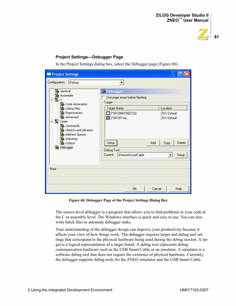
ZiLOG Developer Studio IIZNEO™ User Manual
81
Project Settings—Debugger PageIn the Project Settings dialog box, select the Debugger page (Figure 60).
Figure 60. Debugger Page of the Project Settings Dialog Box
The source-level debugger is a program that allows you to find problems in your code at the C or assembly level. The Windows interface is quick and easy to use. You can also write batch files to automate debugger tasks.
Your understanding of the debugger design can improve your productivity because it affects your view of how things work. The debugger requires target and debug tool set-tings that correspond to the physical hardware being used during the debug session. A tar-get is a logical representation of a target board. A debug tool represents debug communication hardware such as the USB Smart Cable or an emulator. A simulator is a software debug tool that does not require the existence of physical hardware. Currently, the debugger supports debug tools for the ZNEO simulator and the USB Smart Cable.
2 Using the Integrated Development Environment UM017103-0207
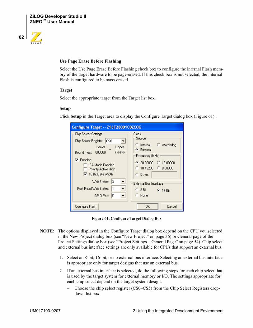
ZiLOG Developer Studio IIZNEO™ User Manual
82
Use Page Erase Before Flashing
Select the Use Page Erase Before Flashing check box to configure the internal Flash mem-ory of the target hardware to be page-erased. If this check box is not selected, the internal Flash is configured to be mass-erased.
Target
Select the appropriate target from the Target list box.
Setup
Click Setup in the Target area to display the Configure Target dialog box (Figure 61).
Figure 61. Configure Target Dialog Box
NOTE: The options displayed in the Configure Target dialog box depend on the CPU you selected in the New Project dialog box (see “New Project” on page 36) or General page of the Project Settings dialog box (see “Project Settings—General Page” on page 54). Chip select and external bus interface settings are only available for CPUs that support an external bus.
1. Select an 8-bit, 16-bit, or no external bus interface. Selecting an external bus interface is appropriate only for target designs that use an external bus.
2. If an external bus interface is selected, do the following steps for each chip select that is used by the target system for external memory or I/O. The settings appropriate for each chip select depend on the target system design.– Choose the chip select register (CS0–CS5) from the Chip Select Registers drop-
down list box.
UM017103-0207 2 Using the Integrated Development Environment
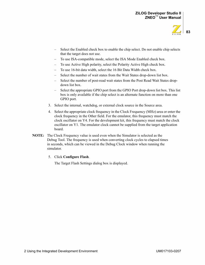
ZiLOG Developer Studio IIZNEO™ User Manual
83
– Select the Enabled check box to enable the chip select. Do not enable chip selects that the target does not use.
– To use ISA-compatible mode, select the ISA Mode Enabled check box.– To use Active High polarity, select the Polarity Active High check box.– To use 16-bit data width, select the 16 Bit Data Width check box.– Select the number of wait states from the Wait States drop-down list box. – Select the number of post-read wait states from the Post Read Wait States drop-
down list box.– Select the appropriate GPIO port from the GPIO Port drop-down list box. This list
box is only available if the chip select is an alternate function on more than one GPIO port.
3. Select the internal, watchdog, or external clock source in the Source area.
4. Select the appropriate clock frequency in the Clock Frequency (MHz) area or enter the clock frequency in the Other field. For the emulator, this frequency must match the clock oscillator on Y4. For the development kit, this frequency must match the clock oscillator on Y1. The emulator clock cannot be supplied from the target application board.
NOTE: The Clock Frequency value is used even when the Simulator is selected as the Debug Tool. The frequency is used when converting clock cycles to elapsed times in seconds, which can be viewed in the Debug Clock window when running the simulator.
5. Click Configure Flash.
The Target Flash Settings dialog box is displayed.
2 Using the Integrated Development Environment UM017103-0207
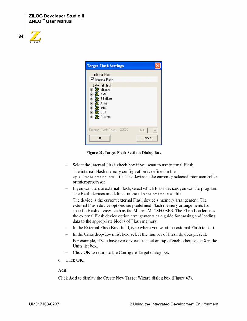
ZiLOG Developer Studio IIZNEO™ User Manual
84
Figure 62. Target Flash Settings Dialog Box
– Select the Internal Flash check box if you want to use internal Flash.The internal Flash memory configuration is defined in the CpuFlashDevice.xml file. The device is the currently selected microcontroller or microprocessor.
– If you want to use external Flash, select which Flash devices you want to program. The Flash devices are defined in the FlashDevice.xml file. The device is the current external Flash device’s memory arrangement. The external Flash device options are predefined Flash memory arrangements for specific Flash devices such as the Micron MT28F008B3. The Flash Loader uses the external Flash device option arrangements as a guide for erasing and loading data to the appropriate blocks of Flash memory.
– In the External Flash Base field, type where you want the external Flash to start.– In the Units drop-down list box, select the number of Flash devices present.
For example, if you have two devices stacked on top of each other, select 2 in the Units list box.
– Click OK to return to the Configure Target dialog box.
6. Click OK.
Add
Click Add to display the Create New Target Wizard dialog box (Figure 63).
UM017103-0207 2 Using the Integrated Development Environment
ZiLOG Developer Studio IIZNEO™ User Manual
85
Figure 63. Create New Target Wizard Dialog Box
Type a unique target name in the field, select the Place Target File in Project Directory check box if you want your new target file to be saved in the same directory as the cur-rently active project, and click Finish.
Copy
Click Copy to display the Target Copy or Move dialog box (Figure 64).
2 Using the Integrated Development Environment UM017103-0207
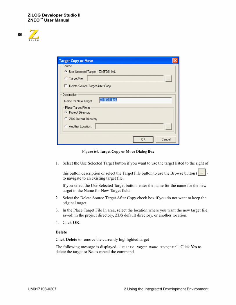
ZiLOG Developer Studio IIZNEO™ User Manual
86
Figure 64. Target Copy or Move Dialog Box
1. Select the Use Selected Target button if you want to use the target listed to the right of this button description or select the Target File button to use the Browse button ( ) to navigate to an existing target file.
If you select the Use Selected Target button, enter the name for the name for the new target in the Name for New Target field.
2. Select the Delete Source Target After Copy check box if you do not want to keep the original target.
3. In the Place Target File In area, select the location where you want the new target file saved: in the project directory, ZDS default directory, or another location.
4. Click OK.
Delete
Click Delete to remove the currently highlighted target
The following message is displayed: “Delete target_name Target?”. Click Yes to delete the target or No to cancel the command.
UM017103-0207 2 Using the Integrated Development Environment
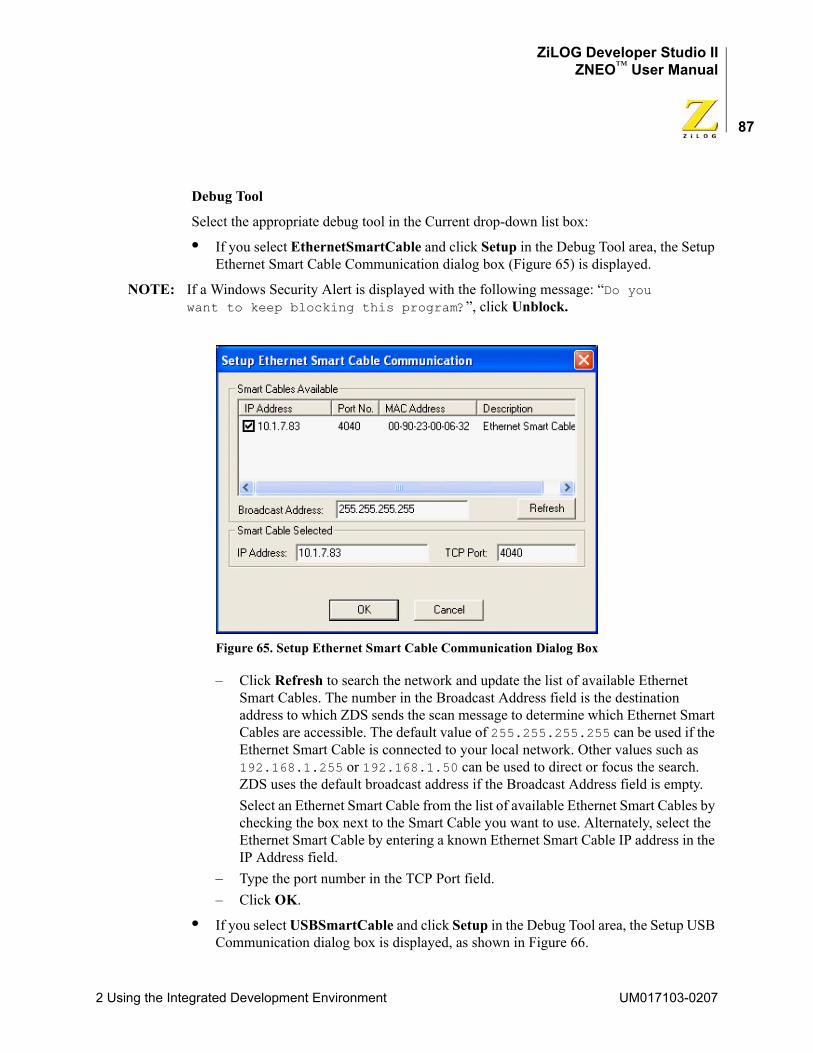
ZiLOG Developer Studio IIZNEO™ User Manual
87
Debug Tool
Select the appropriate debug tool in the Current drop-down list box:
• If you select EthernetSmartCable and click Setup in the Debug Tool area, the Setup Ethernet Smart Cable Communication dialog box (Figure 65) is displayed.
NOTE: If a Windows Security Alert is displayed with the following message: “Do you want to keep blocking this program?”, click Unblock.
Figure 65. Setup Ethernet Smart Cable Communication Dialog Box
– Click Refresh to search the network and update the list of available Ethernet Smart Cables. The number in the Broadcast Address field is the destination address to which ZDS sends the scan message to determine which Ethernet Smart Cables are accessible. The default value of 255.255.255.255 can be used if the Ethernet Smart Cable is connected to your local network. Other values such as 192.168.1.255 or 192.168.1.50 can be used to direct or focus the search. ZDS uses the default broadcast address if the Broadcast Address field is empty.Select an Ethernet Smart Cable from the list of available Ethernet Smart Cables by checking the box next to the Smart Cable you want to use. Alternately, select the Ethernet Smart Cable by entering a known Ethernet Smart Cable IP address in the IP Address field.
– Type the port number in the TCP Port field.– Click OK.
• If you select USBSmartCable and click Setup in the Debug Tool area, the Setup USB Communication dialog box is displayed, as shown in Figure 66.
2 Using the Integrated Development Environment UM017103-0207
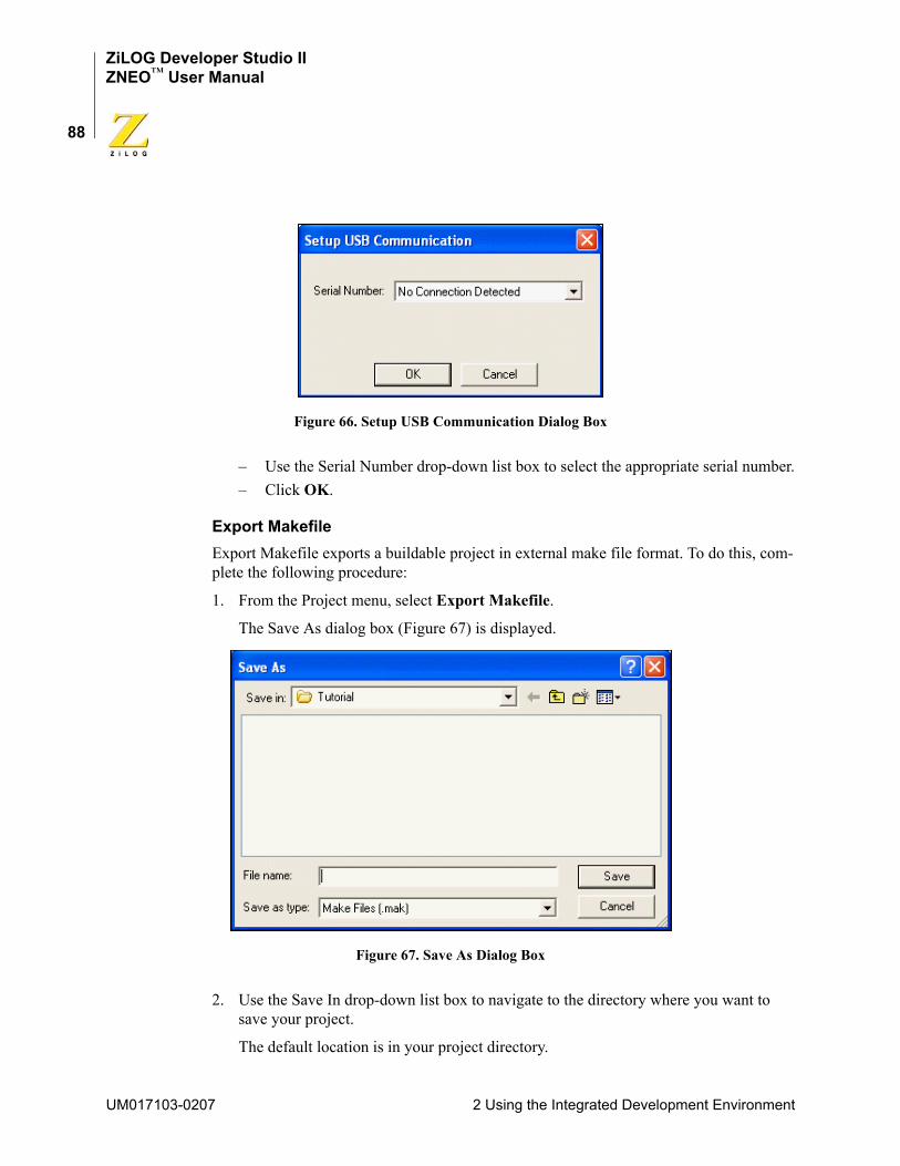
ZiLOG Developer Studio IIZNEO™ User Manual
88
Figure 66. Setup USB Communication Dialog Box
– Use the Serial Number drop-down list box to select the appropriate serial number.– Click OK.
Export MakefileExport Makefile exports a buildable project in external make file format. To do this, com-plete the following procedure:
1. From the Project menu, select Export Makefile.
The Save As dialog box (Figure 67) is displayed.
Figure 67. Save As Dialog Box
2. Use the Save In drop-down list box to navigate to the directory where you want to save your project.
The default location is in your project directory.
UM017103-0207 2 Using the Integrated Development Environment
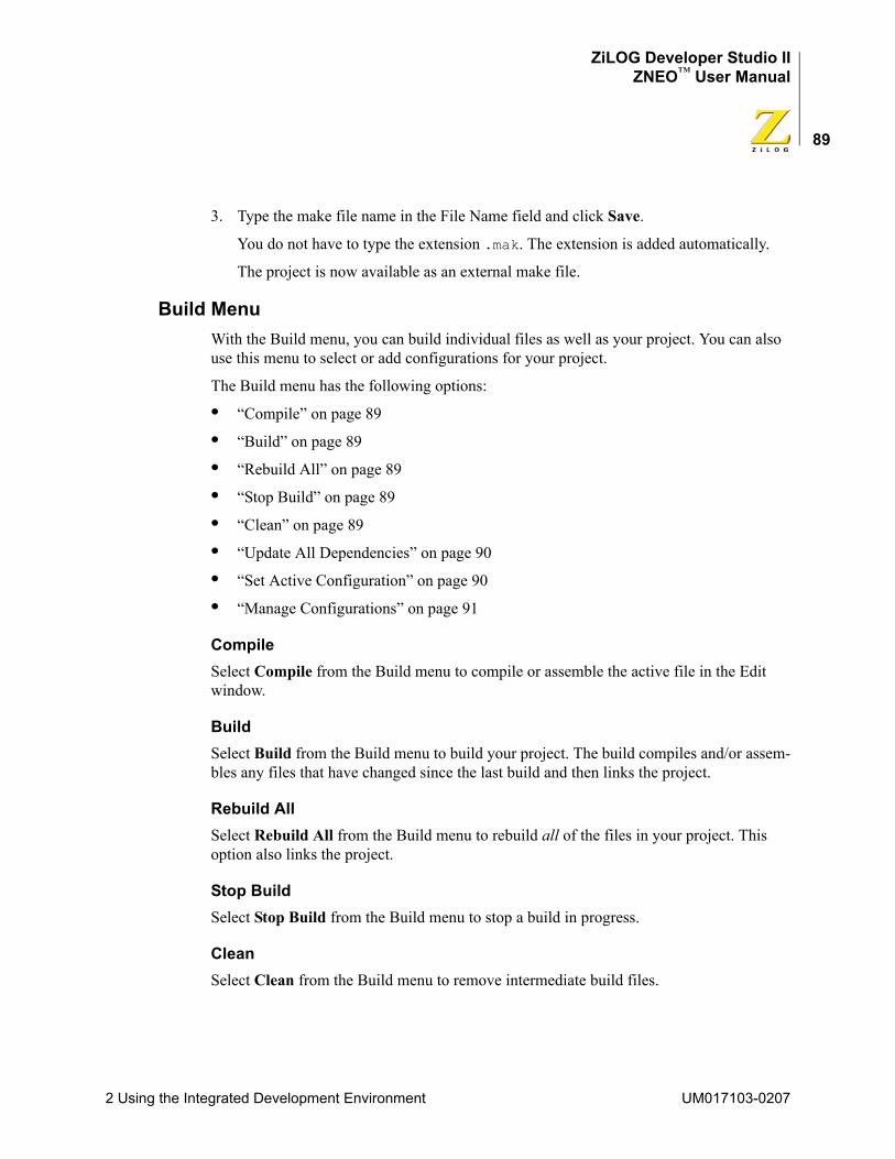
ZiLOG Developer Studio IIZNEO™ User Manual
89
3. Type the make file name in the File Name field and click Save.
You do not have to type the extension .mak. The extension is added automatically.
The project is now available as an external make file.
Build MenuWith the Build menu, you can build individual files as well as your project. You can also use this menu to select or add configurations for your project.
The Build menu has the following options:
• “Compile” on page 89
• “Build” on page 89
• “Rebuild All” on page 89
• “Stop Build” on page 89
• “Clean” on page 89
• “Update All Dependencies” on page 90
• “Set Active Configuration” on page 90
• “Manage Configurations” on page 91
CompileSelect Compile from the Build menu to compile or assemble the active file in the Edit window.
BuildSelect Build from the Build menu to build your project. The build compiles and/or assem-bles any files that have changed since the last build and then links the project.
Rebuild AllSelect Rebuild All from the Build menu to rebuild all of the files in your project. This option also links the project.
Stop BuildSelect Stop Build from the Build menu to stop a build in progress.
CleanSelect Clean from the Build menu to remove intermediate build files.
2 Using the Integrated Development Environment UM017103-0207
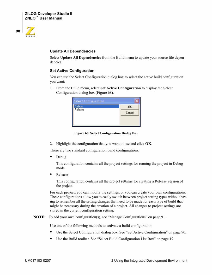
ZiLOG Developer Studio IIZNEO™ User Manual
90
Update All DependenciesSelect Update All Dependencies from the Build menu to update your source file depen-dencies.
Set Active ConfigurationYou can use the Select Configuration dialog box to select the active build configuration you want:
1. From the Build menu, select Set Active Configuration to display the Select Configuration dialog box (Figure 68).
Figure 68. Select Configuration Dialog Box
2. Highlight the configuration that you want to use and click OK.
There are two standard configuration build configurations:
• Debug
This configuration contains all the project settings for running the project in Debug mode.
• Release
This configuration contains all the project settings for creating a Release version of the project.
For each project, you can modify the settings, or you can create your own configurations. These configurations allow you to easily switch between project setting types without hav-ing to remember all the setting changes that need to be made for each type of build that might be necessary during the creation of a project. All changes to project settings are stored in the current configuration setting.
NOTE: To add your own configuration(s), see “Manage Configurations” on page 91.
Use one of the following methods to activate a build configuration:
• Use the Select Configuration dialog box. See “Set Active Configuration” on page 90.
• Use the Build toolbar. See “Select Build Configuration List Box” on page 19.
UM017103-0207 2 Using the Integrated Development Environment
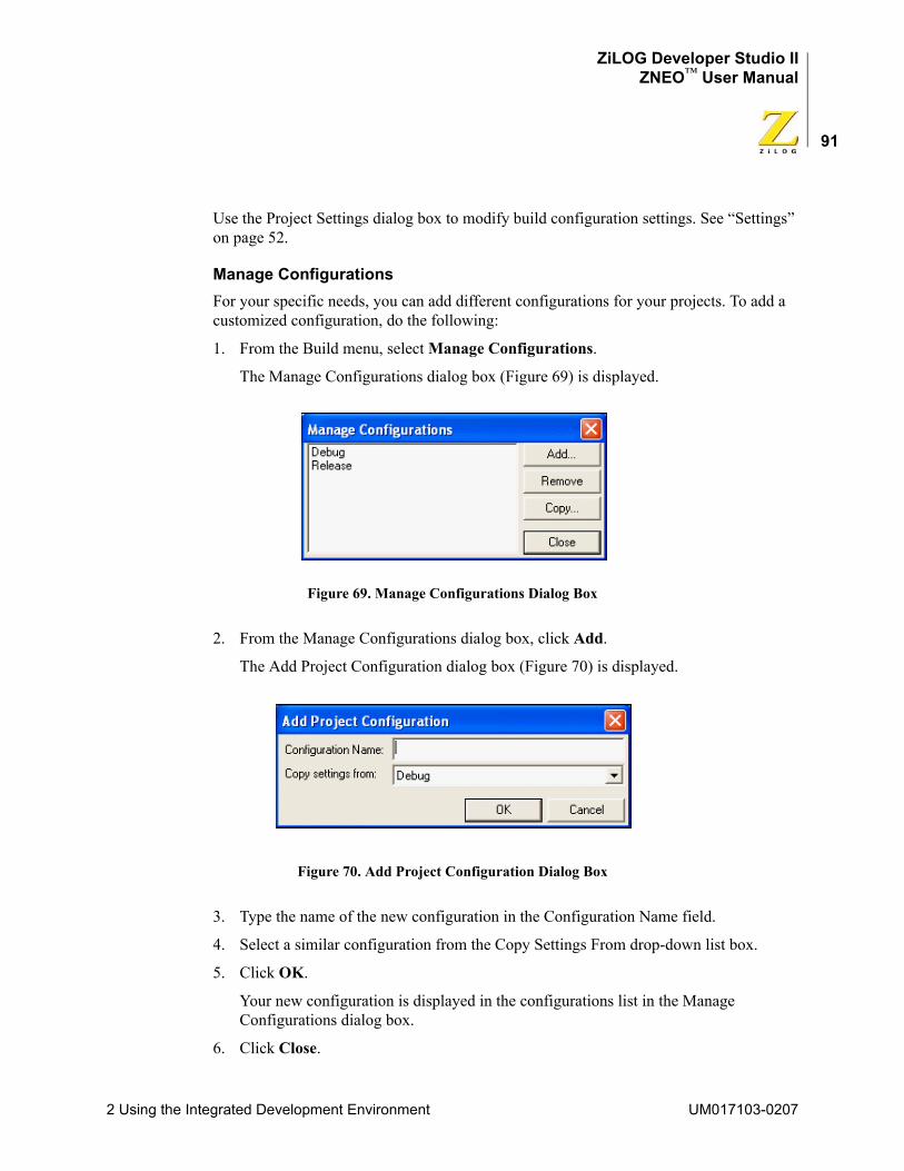
ZiLOG Developer Studio IIZNEO™ User Manual
91
Use the Project Settings dialog box to modify build configuration settings. See “Settings” on page 52.
Manage ConfigurationsFor your specific needs, you can add different configurations for your projects. To add a customized configuration, do the following:
1. From the Build menu, select Manage Configurations.
The Manage Configurations dialog box (Figure 69) is displayed.
Figure 69. Manage Configurations Dialog Box
2. From the Manage Configurations dialog box, click Add.
The Add Project Configuration dialog box (Figure 70) is displayed.
Figure 70. Add Project Configuration Dialog Box
3. Type the name of the new configuration in the Configuration Name field.
4. Select a similar configuration from the Copy Settings From drop-down list box.
5. Click OK.
Your new configuration is displayed in the configurations list in the Manage Configurations dialog box.
6. Click Close.
2 Using the Integrated Development Environment UM017103-0207
ZiLOG Developer Studio IIZNEO™ User Manual
92
The new configuration is the current configuration as shown in the Select Build Configuration drop-down list box on the Build toolbar.
Now that you have created a blank template, you are ready to select the settings for this new configuration.
7. From the Project menu, select Settings.
The Project Settings dialog box is displayed.
8. Select the settings for the new configuration and click OK.
9. From the File menu, select Save All.
Debug MenuUse the Debug menu to access the following functions for the debugger:
• “Connect to Target” on page 92
• “Download Code” on page 93
• “Verify Download” on page 93
• “Stop Debugging” on page 93
• “Reset” on page 93
• “Go” on page 93
• “Run to Cursor” on page 93
• “Break” on page 93
• “Step Into” on page 93
• “Step Over” on page 94
• “Step Out” on page 94
• “Set Next Instruction” on page 94
NOTE: For more information on the Debugger, see the “Using the Debugger” chapter on page 251.
Connect to TargetThe Connect to Target command starts a debug session and initializes the communication to the target hardware. This command does not download the software or reset to main. Use this button to access target registers, memory, and so on, without loading new code or to avoid overwriting the target’s code with the same code. This command is not enabled when the target is the simulator.
UM017103-0207 2 Using the Integrated Development Environment
ZiLOG Developer Studio IIZNEO™ User Manual
93
Download CodeThe Download Code command downloads the executable file for the currently open project to the target for debugging. The command also initializes the communication to the target hardware if it has not been done yet. Use this command anytime during a debug ses-sion. This command is not enabled when the target is the simulator.
NOTE: The current code on the target is overwritten.
Verify DownloadSelect Verify Download from the Debug menu to determine download correctness by comparing executable file contents to target memory.
Stop DebuggingSelect Stop Debugging from the Debug menu to end the current debug session.
To stop program execution, select the Break command.
ResetSelect Reset from the Debug menu to reset the program counter to the beginning of the program. If not in Debug mode, a debug session is started. By default and if possible, the Reset command resets the program counter to symbol 'main'. If you deselect the Reset to Symbol 'main' (Where Applicable) check box on the Debugger tab of the Options dialog box (see page 107), the program counter resets to the first line of the program.
GoSelect Go from the Debug menu to execute project code from the current program counter. If not in Debug mode when the command is selected, a debug session is started.
Run to CursorSelect Run to Cursor from the Debug menu to execute the program code from the current program counter to the line containing the cursor in the active file or the Disassembly window. The cursor must be placed on a valid code line (a C source line with a blue dot displayed in the gutter or any instruction line in the Disassembly window).
BreakSelect Break from the Debug menu to stop program execution at the current program counter.
Step IntoSelect Step Into from the Debug menu to execute one statement or instruction from the current program counter, following execution into function calls. When complete, the pro-gram counter resides at the next program statement or instruction unless a function was
2 Using the Integrated Development Environment UM017103-0207
ZiLOG Developer Studio IIZNEO™ User Manual
94
entered, in which case the program counter resides at the first statement or instruction in the function.
Step OverSelect Step Over from the Debug menu to execute one statement or instruction from the current program counter without following execution into function calls. When complete, the program counter resides at the next program statement or instruction.
Step OutSelect Step Out from the Debug menu to execute the remaining statements or instructions in the current function and returns to the statement or instruction following the call to the current function.
Set Next InstructionSelect Set Next Instruction from the Debug menu to set the program counter to the line containing the cursor in the active file or the Disassembly window.
Tools MenuThe Tools menu lets you set up the Flash Loader, customize the appearance of the ZNEO developer’s environment, update your firmware, and perform a cyclic redundancy check.
The Tools menu has the following options:
• “Flash Loader” on page 94
• “Firmware Upgrade” on page 98
• “Show CRC” on page 98
• “Calculate File Checksum” on page 99
• “Customize” on page 100
• “Options” on page 103
Flash LoaderUse the following procedure to program internal and external Flash for the ZNEO proces-sors:
1. Ensure that the target board is powered up and the emulator is connected and operating properly.
2. In the Configure Target dialog box (see page 82), do the following:
a. If external memory is used on the target, ensure that the appropriate external bus interface is selected and that each chip select register used on the target is enabled and configured properly.
UM017103-0207 2 Using the Integrated Development Environment
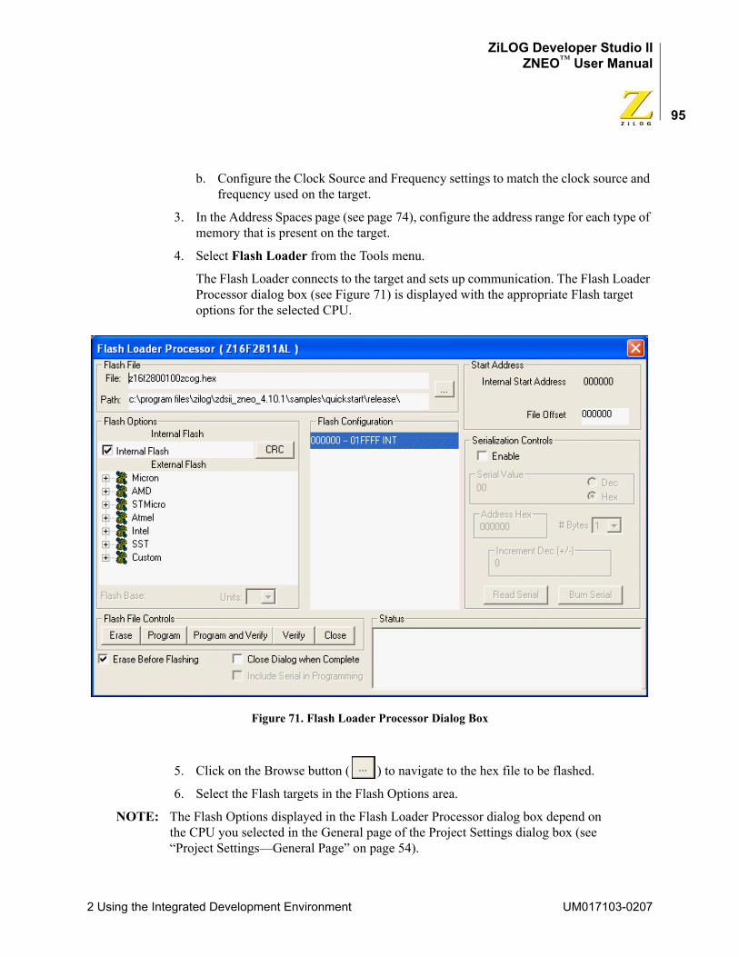
ZiLOG Developer Studio IIZNEO™ User Manual
95
b. Configure the Clock Source and Frequency settings to match the clock source and frequency used on the target.
3. In the Address Spaces page (see page 74), configure the address range for each type of memory that is present on the target.
4. Select Flash Loader from the Tools menu.
The Flash Loader connects to the target and sets up communication. The Flash Loader Processor dialog box (see Figure 71) is displayed with the appropriate Flash target options for the selected CPU.
Figure 71. Flash Loader Processor Dialog Box
5. Click on the Browse button ( ) to navigate to the hex file to be flashed.
6. Select the Flash targets in the Flash Options area.
NOTE: The Flash Options displayed in the Flash Loader Processor dialog box depend on the CPU you selected in the General page of the Project Settings dialog box (see “Project Settings—General Page” on page 54).
2 Using the Integrated Development Environment UM017103-0207
ZiLOG Developer Studio IIZNEO™ User Manual
96
You must select at least one of the following check boxes in the Flash Options area before erasing or flashing a target:– Internal Flash
The internal Flash memory configuration is defined in the CpuFlashDevice.xml file. The device is the currently selected microcontroller or microprocessor. When the internal Flash is selected, the address range is displayed in the Flash Configuration area with an INT extension.
– External FlashIf you select the External Flash check box, select which Flash devices you want to program. The Flash devices are defined in the FlashDevice.xml file. The device is the current external Flash device’s memory arrangement. When an external Flash device is selected, the Flash Loader uses the address specified in the Flash Base field to begin searching for the selected Flash device. The Flash Loader reads each page of memory from the FlashDevice.xml file, checking if the page is enabled by the chip select register settings. It then queries the actual address to verify that the correct Flash device is found. If the correct Flash device is found, the page’s range with an EXT extension and chip select register are displayed in the Flash Configuration area.The external Flash device options are predefined Flash memory arrangements for specific Flash devices such as the Micron MT28F008B3. The Flash Loader uses the external Flash device option arrangements as a guide for erasing and loading the Intel hexadecimal file in the appropriate blocks of memory.
NOTE: The Flash Loader is unable to identify, erase, or write to a page of Flash that is protected through hardware. For example, a target might have a write enable jumper to protect the boot block. In this case, the write enable jumper must be set before flashing the area of Flash. The Flash Loader displays this page as disabled.
7. To perform a cyclic redundancy check on the whole internal Flash memory, click CRC.
The checksum is displayed in the Status area of the Flash Loader Processor dialog box.
8. In the Flash Base field, type where you want the Flash programming to start.
The Flash base defines the start of external Flash.
9. In the Units drop-down list box, select the number of Flash devices to program.
For example, if you have two devices stacked on top of each other, select 2 in the Units list box.
10. Select the pages to erase before flashing in the Flash Configuration area.
Pages that are grayed out are not available.
UM017103-0207 2 Using the Integrated Development Environment
ZiLOG Developer Studio IIZNEO™ User Manual
97
11. Type the appropriate offset values in the File Offset field to offset the base address of the hex file.
NOTE: The hex file address is shifted by the offset defined in the Start Address area. You need to allow for the shift in any defined jump table index. This offset value also shifts the erase range for the Flash.
12. Select the Erase Before Flashing check box to erase all Flash memory before writing the hex file to Flash memory.
You can also delete the Flash memory by clicking ERASE. Clicking ERASE deletes only the pages that are selected.
13. Select the Close Dialog When Complete check box to close the dialog box after writing the hex file to Flash memory.
14. Use the following procedure if you want to use the serialization feature:
a. Select the Include Serial in Programming check box. This option programs the serial number after the selected hex file has been written to Flash.
b. Select the Enable check box.
c. Type in the start value for the serial number in the Serial Value field and select the Dec button for a decimal serial number or the Hex button for a hexadecimal serial number.
d. Type the location you want the serial number located in the Address Hex field.
e. Select the number of bytes that you want the serial number to occupy in the # Bytes drop-down list box.
f. Type the decimal interval that you want the serial number incremented by in the Increment Dec (+/-) field. If you want the serial number to be decremented, type in a negative number. After the current serial number is programmed, the serial number is then incremented or decremented by the amount in the Increment Dec (+/-) field.
g. Select the Erase Before Flashing check box. This option erases the Flash before writing the serial number.
h. Click Burn Serial to write the serial number to the current device or click Program or Program and Verify to program the Flash memory with the specified hex file and write the serial number.
15. If you want to check a serial number that has already been programmed at an address, do the following:
a. Select the Enable check box.
b. Type the address that you want to read in the Address Hex field.
Caution:
2 Using the Integrated Development Environment UM017103-0207
ZiLOG Developer Studio IIZNEO™ User Manual
98
c. Select the number of bytes to read from # Bytes drop-down list box.
d. Click Read Serial to check the serial number for the current device.
16. Program the Flash memory by clicking one of the following buttons:– Click Program to write the hex file to Flash memory and perform no checking
while writing.– Click Program and Verify to write the hex file to Flash memory by writing a
segment of data and then reading back the segment and verifying that it has been written correctly.
17. Verify the Flash memory by clicking Verify.
When you click Verify, the Flash Loader reads and compares the hex file contents with the current contents of Flash memory. This function does not change target Flash memory.
Firmware UpgradeNOTE: This command is available only when a supporting debug tool is selected (“Debug
Tool” on page 87).
• USB Smart Cable
<ZDS Installation Directory>\bin\firmware\USBSmartCable\USBSmartCable upgrade information.txt
• Serial Smart Cable
This is not available for this release.
• Ethernet Smart Cable
<ZDS Installation Directory>\bin\firmware\EthernetSmartCable\EthernetSmartCable upgrade information.txt
Show CRCNOTE: This command is only available when the target is not a simulator.
Use the following procedure to perform a cyclic redundancy check (CRC):
1. Select Show CRC from the Tools menu.
The Show CRC dialog box (Figure 72) is displayed.
UM017103-0207 2 Using the Integrated Development Environment
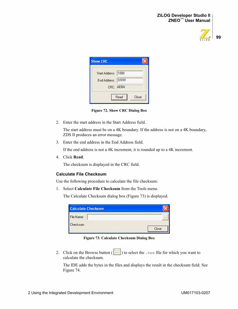
ZiLOG Developer Studio IIZNEO™ User Manual
99
Figure 72. Show CRC Dialog Box
2. Enter the start address in the Start Address field.
The start address must be on a 4K boundary. If the address is not on a 4K boundary, ZDS II produces an error message.
3. Enter the end address in the End Address field.
If the end address is not a 4K increment, it is rounded up to a 4K increment.
4. Click Read.
The checksum is displayed in the CRC field.
Calculate File ChecksumUse the following procedure to calculate the file checksum:
1. Select Calculate File Checksum from the Tools menu.
The Calculate Checksum dialog box (Figure 73) is displayed.
Figure 73. Calculate Checksum Dialog Box
2. Click on the Browse button ( ) to select the .hex file for which you want to calculate the checksum.
The IDE adds the bytes in the files and displays the result in the checksum field. See Figure 74.
2 Using the Integrated Development Environment UM017103-0207
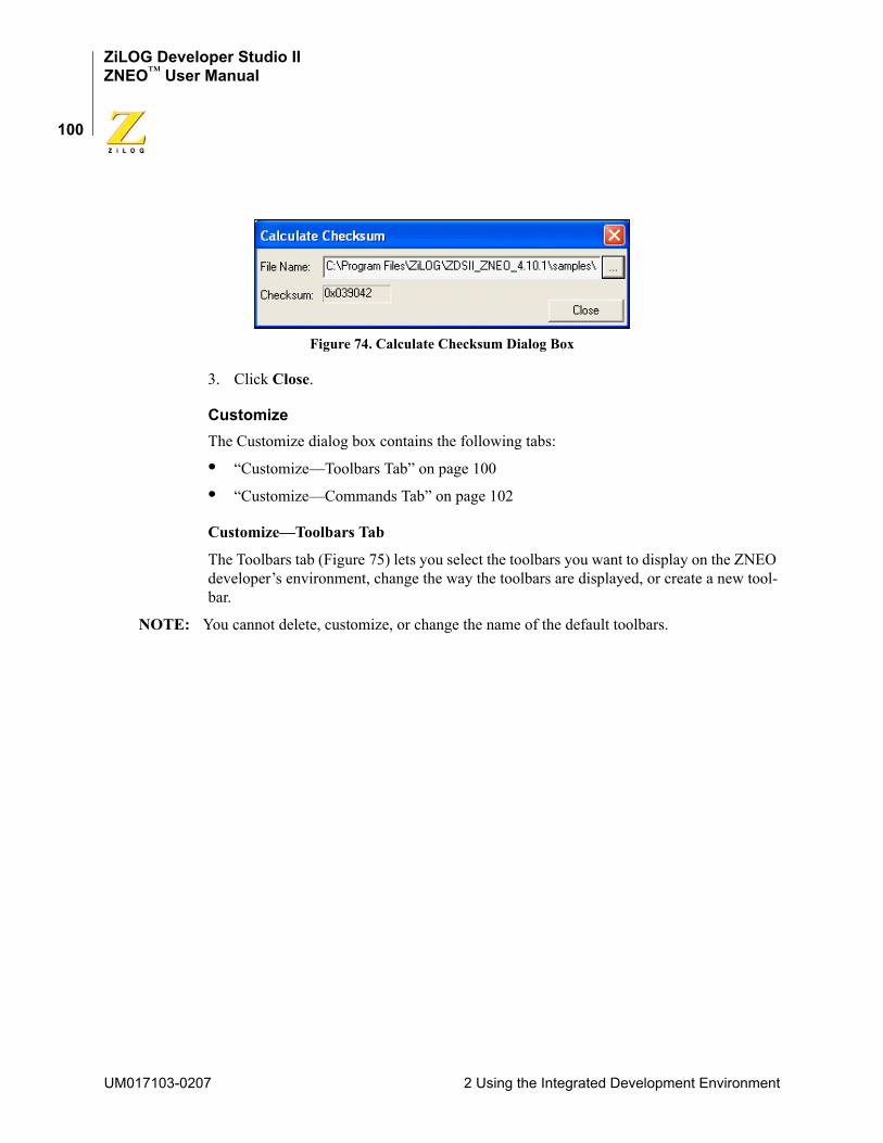
ZiLOG Developer Studio IIZNEO™ User Manual
100
Figure 74. Calculate Checksum Dialog Box
3. Click Close.
CustomizeThe Customize dialog box contains the following tabs:
• “Customize—Toolbars Tab” on page 100
• “Customize—Commands Tab” on page 102
Customize—Toolbars Tab
The Toolbars tab (Figure 75) lets you select the toolbars you want to display on the ZNEO developer’s environment, change the way the toolbars are displayed, or create a new tool-bar.
NOTE: You cannot delete, customize, or change the name of the default toolbars.
UM017103-0207 2 Using the Integrated Development Environment
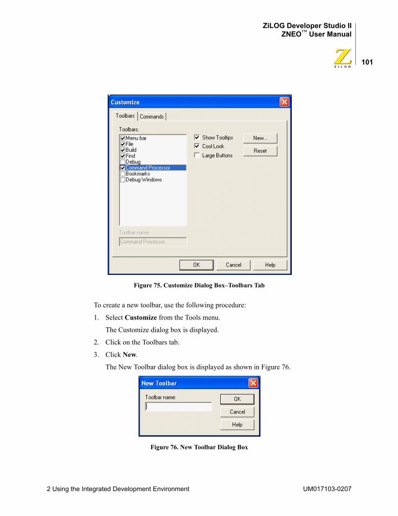
ZiLOG Developer Studio IIZNEO™ User Manual
101
Figure 75. Customize Dialog Box–Toolbars Tab
To create a new toolbar, use the following procedure:
1. Select Customize from the Tools menu.
The Customize dialog box is displayed.
2. Click on the Toolbars tab.
3. Click New.
The New Toolbar dialog box is displayed as shown in Figure 76.
Figure 76. New Toolbar Dialog Box
2 Using the Integrated Development Environment UM017103-0207
ZiLOG Developer Studio IIZNEO™ User Manual
102
4. In the Toolbar Name field, type the name of the new toolbar.
5. Click OK.
The new toolbar is displayed as a gray box.
You can change the name by selecting the new toolbar in the toolbars list box, typing a new name in the Toolbar Name field, and pressing the Enter key.
6. Click the Commands tab.
7. Drag buttons from any category to your new toolbar.
NOTE: To delete the new toolbar, select the new toolbar in the Toolbars list box and click Delete.
8. Click OK to apply your changes or click Cancel to close the dialog box without making any changes.
Customize—Commands Tab
The Commands tab lets you modify the following by selecting the appropriate categories:
• “File Toolbar” on page 17
• “Find Toolbar” on page 20
• “Build Toolbar” on page 18
• “Debug Toolbar” on page 22
• “Debug Windows Toolbar” on page 24
• “Command Processor Toolbar” on page 21
• “Menu Bar” on page 34
To see a description of each toolbar button, highlight the icon as shown in Figure 77.
UM017103-0207 2 Using the Integrated Development Environment
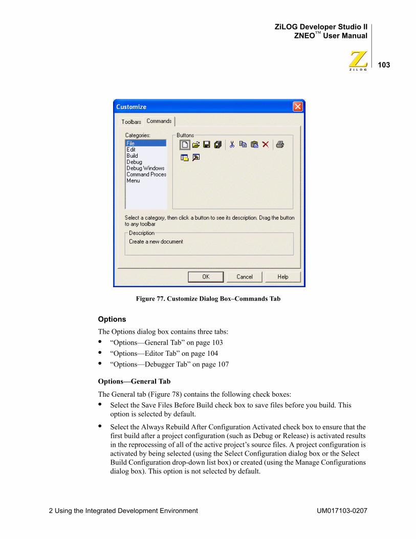
ZiLOG Developer Studio IIZNEO™ User Manual
103
Figure 77. Customize Dialog Box–Commands Tab
OptionsThe Options dialog box contains three tabs:• “Options—General Tab” on page 103• “Options—Editor Tab” on page 104• “Options—Debugger Tab” on page 107
Options—General Tab
The General tab (Figure 78) contains the following check boxes:• Select the Save Files Before Build check box to save files before you build. This
option is selected by default.
• Select the Always Rebuild After Configuration Activated check box to ensure that the first build after a project configuration (such as Debug or Release) is activated results in the reprocessing of all of the active project’s source files. A project configuration is activated by being selected (using the Select Configuration dialog box or the Select Build Configuration drop-down list box) or created (using the Manage Configurations dialog box). This option is not selected by default.
2 Using the Integrated Development Environment UM017103-0207
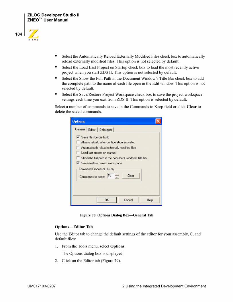
ZiLOG Developer Studio IIZNEO™ User Manual
104
• Select the Automatically Reload Externally Modified Files check box to automatically reload externally modified files. This option is not selected by default.
• Select the Load Last Project on Startup check box to load the most recently active project when you start ZDS II. This option is not selected by default.
• Select the Show the Full Path in the Document Window’s Title Bar check box to add the complete path to the name of each file open in the Edit window. This option is not selected by default.
• Select the Save/Restore Project Workspace check box to save the project workspace settings each time you exit from ZDS II. This option is selected by default.
Select a number of commands to save in the Commands to Keep field or click Clear to delete the saved commands.
Figure 78. Options Dialog Box—General Tab
Options—Editor Tab
Use the Editor tab to change the default settings of the editor for your assembly, C, and default files:
1. From the Tools menu, select Options.
The Options dialog box is displayed.
2. Click on the Editor tab (Figure 79).
UM017103-0207 2 Using the Integrated Development Environment
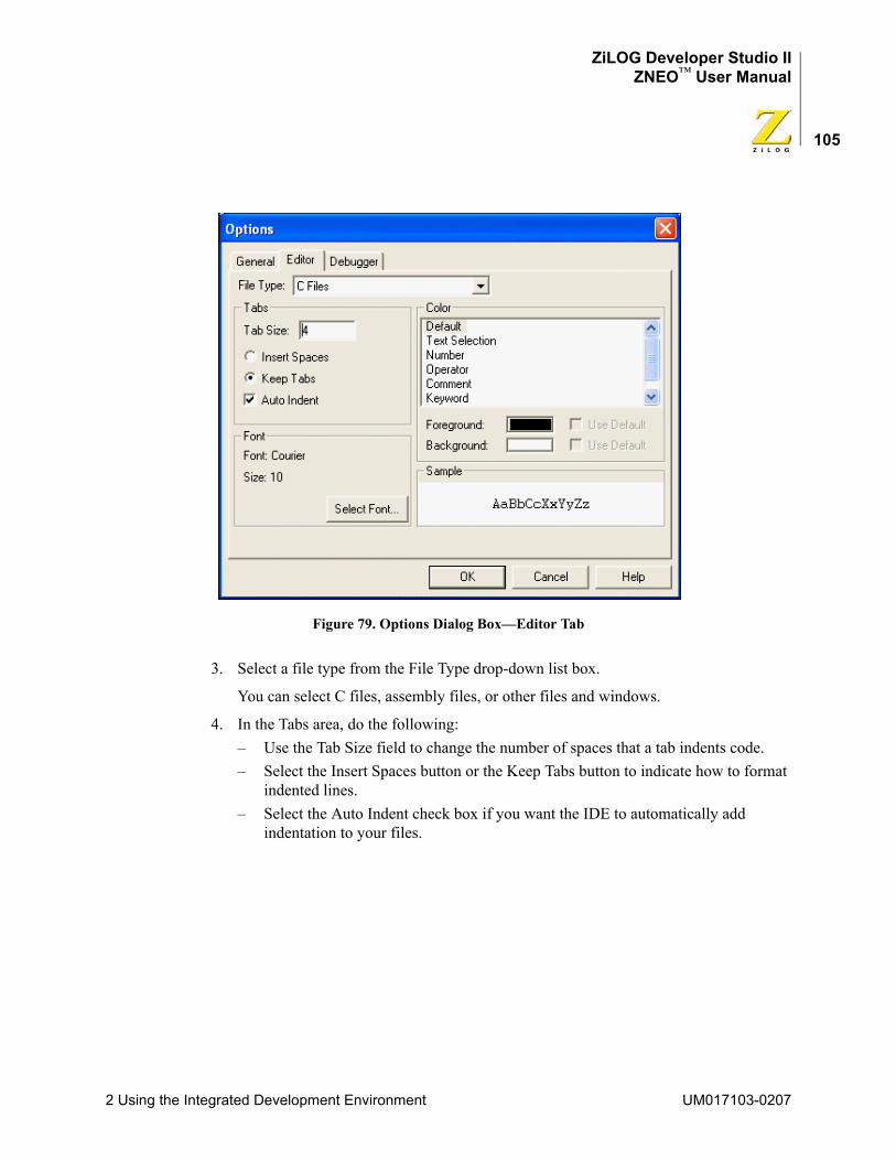
ZiLOG Developer Studio IIZNEO™ User Manual
105
Figure 79. Options Dialog Box—Editor Tab
3. Select a file type from the File Type drop-down list box.
You can select C files, assembly files, or other files and windows.
4. In the Tabs area, do the following:– Use the Tab Size field to change the number of spaces that a tab indents code.– Select the Insert Spaces button or the Keep Tabs button to indicate how to format
indented lines.– Select the Auto Indent check box if you want the IDE to automatically add
indentation to your files.
2 Using the Integrated Development Environment UM017103-0207
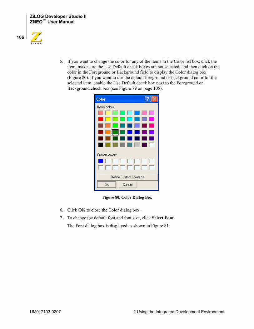
ZiLOG Developer Studio IIZNEO™ User Manual
106
5. If you want to change the color for any of the items in the Color list box, click the item, make sure the Use Default check boxes are not selected, and then click on the color in the Foreground or Background field to display the Color dialog box (Figure 80). If you want to use the default foreground or background color for the selected item, enable the Use Default check box next to the Foreground or Background check box (see Figure 79 on page 105).
Figure 80. Color Dialog Box
6. Click OK to close the Color dialog box.
7. To change the default font and font size, click Select Font.
The Font dialog box is displayed as shown in Figure 81.
UM017103-0207 2 Using the Integrated Development Environment
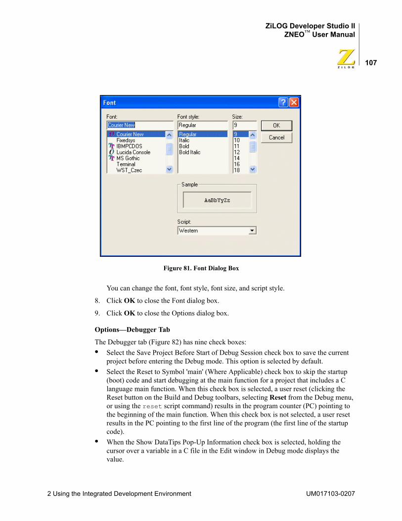
ZiLOG Developer Studio IIZNEO™ User Manual
107
Figure 81. Font Dialog Box
You can change the font, font style, font size, and script style.
8. Click OK to close the Font dialog box.
9. Click OK to close the Options dialog box.
Options—Debugger Tab
The Debugger tab (Figure 82) has nine check boxes:• Select the Save Project Before Start of Debug Session check box to save the current
project before entering the Debug mode. This option is selected by default.• Select the Reset to Symbol 'main' (Where Applicable) check box to skip the startup
(boot) code and start debugging at the main function for a project that includes a C language main function. When this check box is selected, a user reset (clicking the Reset button on the Build and Debug toolbars, selecting Reset from the Debug menu, or using the reset script command) results in the program counter (PC) pointing to the beginning of the main function. When this check box is not selected, a user reset results in the PC pointing to the first line of the program (the first line of the startup code).
• When the Show DataTips Pop-Up Information check box is selected, holding the cursor over a variable in a C file in the Edit window in Debug mode displays the value.
2 Using the Integrated Development Environment UM017103-0207
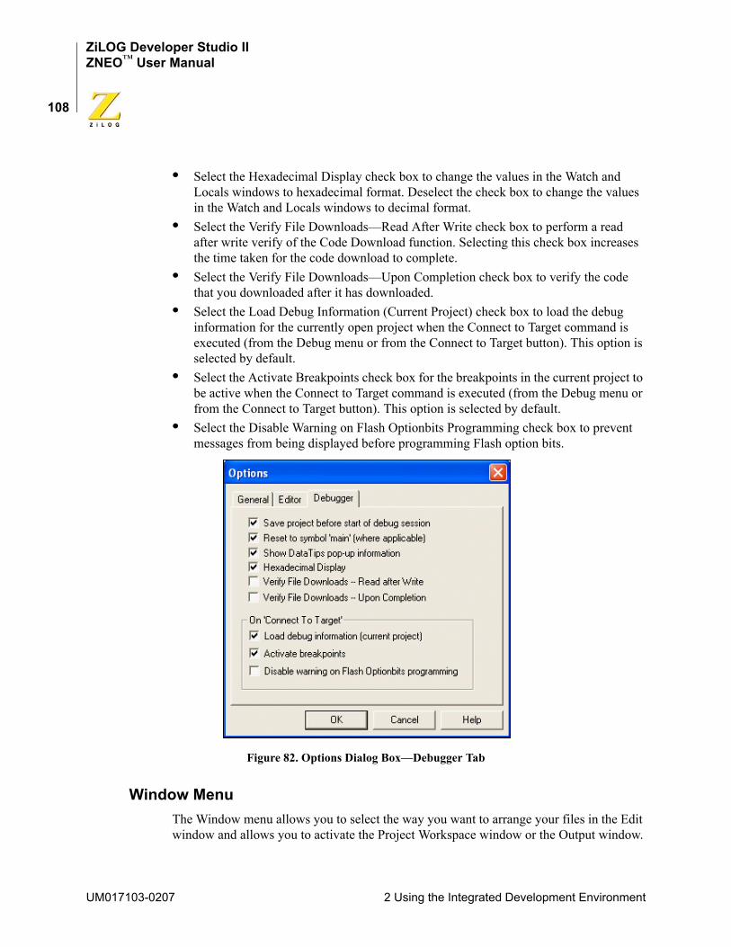
ZiLOG Developer Studio IIZNEO™ User Manual
108
• Select the Hexadecimal Display check box to change the values in the Watch and Locals windows to hexadecimal format. Deselect the check box to change the values in the Watch and Locals windows to decimal format.
• Select the Verify File Downloads—Read After Write check box to perform a read after write verify of the Code Download function. Selecting this check box increases the time taken for the code download to complete.
• Select the Verify File Downloads—Upon Completion check box to verify the code that you downloaded after it has downloaded.
• Select the Load Debug Information (Current Project) check box to load the debug information for the currently open project when the Connect to Target command is executed (from the Debug menu or from the Connect to Target button). This option is selected by default.
• Select the Activate Breakpoints check box for the breakpoints in the current project to be active when the Connect to Target command is executed (from the Debug menu or from the Connect to Target button). This option is selected by default.
• Select the Disable Warning on Flash Optionbits Programming check box to prevent messages from being displayed before programming Flash option bits.
Figure 82. Options Dialog Box—Debugger Tab
Window MenuThe Window menu allows you to select the way you want to arrange your files in the Edit window and allows you to activate the Project Workspace window or the Output window.
UM017103-0207 2 Using the Integrated Development Environment
ZiLOG Developer Studio IIZNEO™ User Manual
109
The Windows menu contains the following options:
• “New Window” on page 109
• “Close” on page 109
• “Close All” on page 109
• “Cascade” on page 109
• “Tile” on page 109
• “Arrange Icons” on page 109
New WindowSelect New Window to create a copy of the file you have active in the Edit window.
CloseSelect Close to close the active file in the Edit window.
Close AllSelect Close All to close all the files in the Edit window.
CascadeSelect Cascade to cascade the files in the Edit window. Use this option to display all open windows whenever you cannot locate a window.
TileSelect Tile to tile the files in the Edit window so that you can see all of them at once.
Arrange IconsSelect Arrange Icons to arrange the files alphabetically in the Edit window.
Help MenuThe Help menu contains the following options:
• “Help Topics” on page 109
• “Technical Support” on page 110
• “About” on page 110
Help TopicsSelect Help Topics to display the ZDS II online help.
2 Using the Integrated Development Environment UM017103-0207
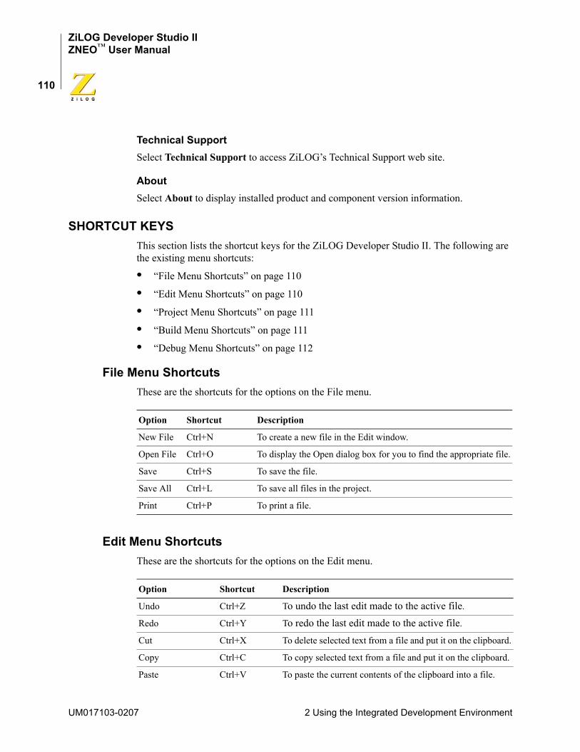
ZiLOG Developer Studio IIZNEO™ User Manual
110
Technical SupportSelect Technical Support to access ZiLOG’s Technical Support web site.
AboutSelect About to display installed product and component version information.
SHORTCUT KEYSThis section lists the shortcut keys for the ZiLOG Developer Studio II. The following are the existing menu shortcuts:
• “File Menu Shortcuts” on page 110
• “Edit Menu Shortcuts” on page 110
• “Project Menu Shortcuts” on page 111
• “Build Menu Shortcuts” on page 111
• “Debug Menu Shortcuts” on page 112
File Menu ShortcutsThese are the shortcuts for the options on the File menu.
Edit Menu ShortcutsThese are the shortcuts for the options on the Edit menu.
Option Shortcut Description
New File Ctrl+N To create a new file in the Edit window.
Open File Ctrl+O To display the Open dialog box for you to find the appropriate file.
Save Ctrl+S To save the file.
Save All Ctrl+L To save all files in the project.
Print Ctrl+P To print a file.
Option Shortcut Description
Undo Ctrl+Z To undo the last edit made to the active file.
Redo Ctrl+Y To redo the last edit made to the active file.
Cut Ctrl+X To delete selected text from a file and put it on the clipboard.
Copy Ctrl+C To copy selected text from a file and put it on the clipboard.
Paste Ctrl+V To paste the current contents of the clipboard into a file.
UM017103-0207 2 Using the Integrated Development Environment
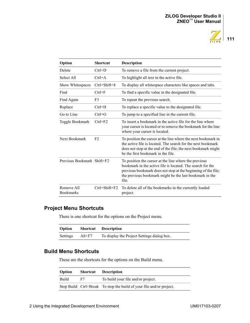
ZiLOG Developer Studio IIZNEO™ User Manual
111
Project Menu ShortcutsThere is one shortcut for the options on the Project menu.
Build Menu ShortcutsThese are the shortcuts for the options on the Build menu.
Delete Ctrl+D To remove a file from the current project.
Select All Ctrl+A To highlight all text in the active file.
Show Whitespaces Ctrl+Shift+8 To display all whitespace characters like spaces and tabs.
Find Ctrl+F To find a specific value in the designated file.
Find Again F3 To repeat the previous search.
Replace Ctrl+H To replace a specific value to the designated file.
Go to Line Ctrl+G To jump to a specified line in the current file.
Toggle Bookmark Ctrl+F2 To insert a bookmark in the active file for the line where your cursor is located or to remove the bookmark for the line where your cursor is located.
Next Bookmark F2 To position the cursor at the line where the next bookmark in the active file is located. The search for the next bookmark does not stop at the end of the file; the next bookmark might be the first bookmark in the file.
Previous Bookmark Shift+F2 To position the cursor at the line where the previous bookmark in the active file is located. The search for the previous bookmark does not stop at the beginning of the file; the previous bookmark might be the last bookmark in the file.
Remove All Bookmarks
Ctrl+Shift+F2 To delete all of the bookmarks in the currently loaded project.
Option Shortcut Description
Settings Alt+F7 To display the Project Settings dialog box.
Option Shortcut Description
Build F7 To build your file and/or project.
Stop Build Ctrl+Break To stop the build of your file and/or project.
Option Shortcut Description
2 Using the Integrated Development Environment UM017103-0207
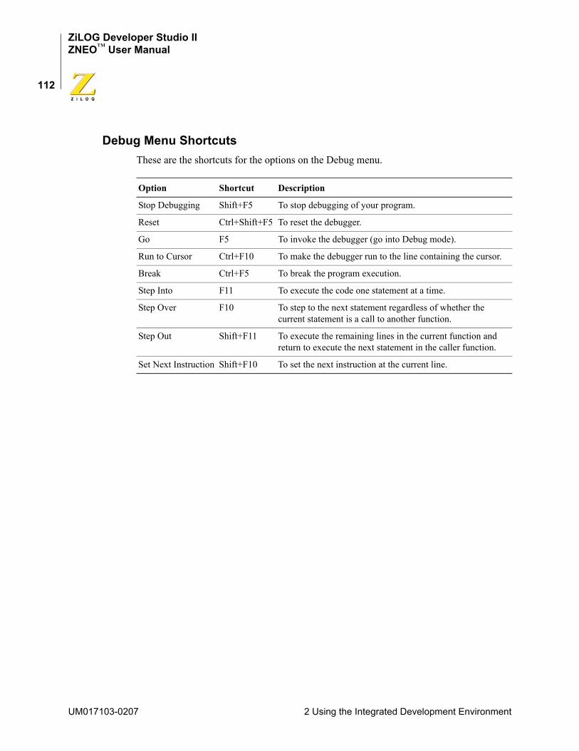
ZiLOG Developer Studio IIZNEO™ User Manual
112
Debug Menu ShortcutsThese are the shortcuts for the options on the Debug menu.
Option Shortcut Description
Stop Debugging Shift+F5 To stop debugging of your program.
Reset Ctrl+Shift+F5 To reset the debugger.
Go F5 To invoke the debugger (go into Debug mode).
Run to Cursor Ctrl+F10 To make the debugger run to the line containing the cursor.
Break Ctrl+F5 To break the program execution.
Step Into F11 To execute the code one statement at a time.
Step Over F10 To step to the next statement regardless of whether the current statement is a call to another function.
Step Out Shift+F11 To execute the remaining lines in the current function and return to execute the next statement in the caller function.
Set Next Instruction Shift+F10 To set the next instruction at the current line.
UM017103-0207 2 Using the Integrated Development Environment
ZiLOG Developer Studio IIZNEO™ User Manual
113
3 Using the ANSI C-CompilerThe ZNEO C-Compiler is a conforming freestanding 1989 ANSI C implementation with some exceptions. These exceptions are described in the ANSI Standard Compliance sec-tion. In accordance with the definition of a freestanding implementation, the compiler accepts programs that confine the use of the features of the ANSI standard library to the contents of the standard headers <float.h>, <limits.h>, <stdarg.h> and <stddef.h>. The ZNEO compiler release supports more of the standard library than is required of a freestanding implementation as listed in “Run-Time Library” on page 133.
The ZNEO C-Compiler supports language extensions for easy programming of the ZNEO processor architecture, which include support for different address spaces and interrupt function designation. The language extensions are described in “Language Extensions” on page 114.
This chapter describes the various features of the ZNEO C-Compiler. It consists of the fol-lowing sections:
• “Language Extensions” on page 114
• “Type Sizes” on page 126
• “Predefined Macros” on page 127
• “Calling Conventions” on page 128
• “Calling Assembly Functions from C” on page 131
• “Calling C Functions from Assembly” on page 132
• “Command Line Options” on page 133
• “Run-Time Library” on page 133
• “Stack Pointer Overflow” on page 142
• “Startup Files” on page 142
• “Segment Naming” on page 143
• “Linker Command Files for C Programs” on page 144
• “ANSI Standard Compliance” on page 150
• “Warning and Error Messages” on page 152
The ZNEO C-Compiler is optimized for embedded applications in which execution speed and code size are crucial.
3 Using the ANSI C-Compiler UM017103-0207
ZiLOG Developer Studio IIZNEO™ User Manual
114
LANGUAGE EXTENSIONSTo give you additional control over the way the ZNEO C-Compiler allocates storage and to enhance its ability to handle common real-time constructs, the compiler implements the following extensions to the ANSI C standard:
• “Additional Keywords for Storage Specification” on page 115
The compiler divides the ZNEO CPU memory into four memory spaces: Near ROM, Extended ROM, Near RAM, and Extended (Far) RAM. It provides the following keywords with which you can control the storage location of data in these memory spaces: – _Near (near)– _Far (far)– _Rom (rom)– _Erom (erom)
These keywords can also be used to specify the memory space to which a pointer is pointing to.
• “Memory Models” on page 119
The compiler supports two memory models: small and large. These models allow you to control where data are stored by default. Each application can only use one model. The model can affect the efficiency of your application. Some of the memory allocation defaults associated with a memory model can be overridden using the keywords for storage specification.
• “Interrupt Support” on page 120
The ZNEO CPU supports various interrupts. The C-Compiler provides language extensions to designate a function as interrupt service routine and provides features to set each interrupt vector.
• “Placement Directives” on page 121
The placement directives allow users to place objects at specific hardware addresses and align objects at a given alignment.
• “String Placement” on page 122
Because the ZNEO CPU has multiple address spaces, the C-Compiler provides language extensions to specify the storage for string constants.
• “Inline Assembly” on page 123
The C-Compiler provides directives for embedding assembly instructions and directives into the C program.
UM017103-0207 3 Using the ANSI C-Compiler
ZiLOG Developer Studio IIZNEO™ User Manual
115
• “Char and Short Enumerations” on page 124
The enumeration data type is defined as int as per ANSI C. The C-Compiler provides language extension to specify the enumeration data type to be other than int.
• “Setting Flash Option Bytes in C” on page 125
The ZNEO CPU has four Flash option bytes. The C-Compiler provides language extension to define these Flash option bytes.
• “Supported New Features from the 1999 Standard” on page 125
The ZNEO C-Compiler is based on the 1989 ANSI C standard. Some new features from the 1999 standard are supported in this compiler for ease of use.
Additional Keywords for Storage SpecificationThe _Near, _Far, _Rom, and _Erom keywords are storage class specifiers and are used to control the allocation of data objects by the compiler. They can be used on individual data objects similar to const and volatile keywords in the ANSI C standard. The storage specifiers can only be used to control the allocation of global and static data. The alloca-tion of local data (nonstatic local) and function parameters is decided by the compiler and is described in later sections. Any storage specifier used on local and parameter data is ignored by the compiler.
The ZiLOG header file <zneo.h> defines macros to permit the use of more familiar key-words: near, far, rom, and erom. The reason for not using these keywords directly is to avoid conflict with C identifiers in a preexisting C program. (To avoid conflicts, current ANSI recommendations are that keywords for vendor extensions to the C language begin with an underscore and capitol letter.)
The data allocation for various storage class specifiers is shown in Figure 83 and described in the following sections:
• “_Near” on page 116
• “_Rom” on page 116
• “_Erom” on page 116
• “_Far” on page 117
3 Using the ANSI C-Compiler UM017103-0207
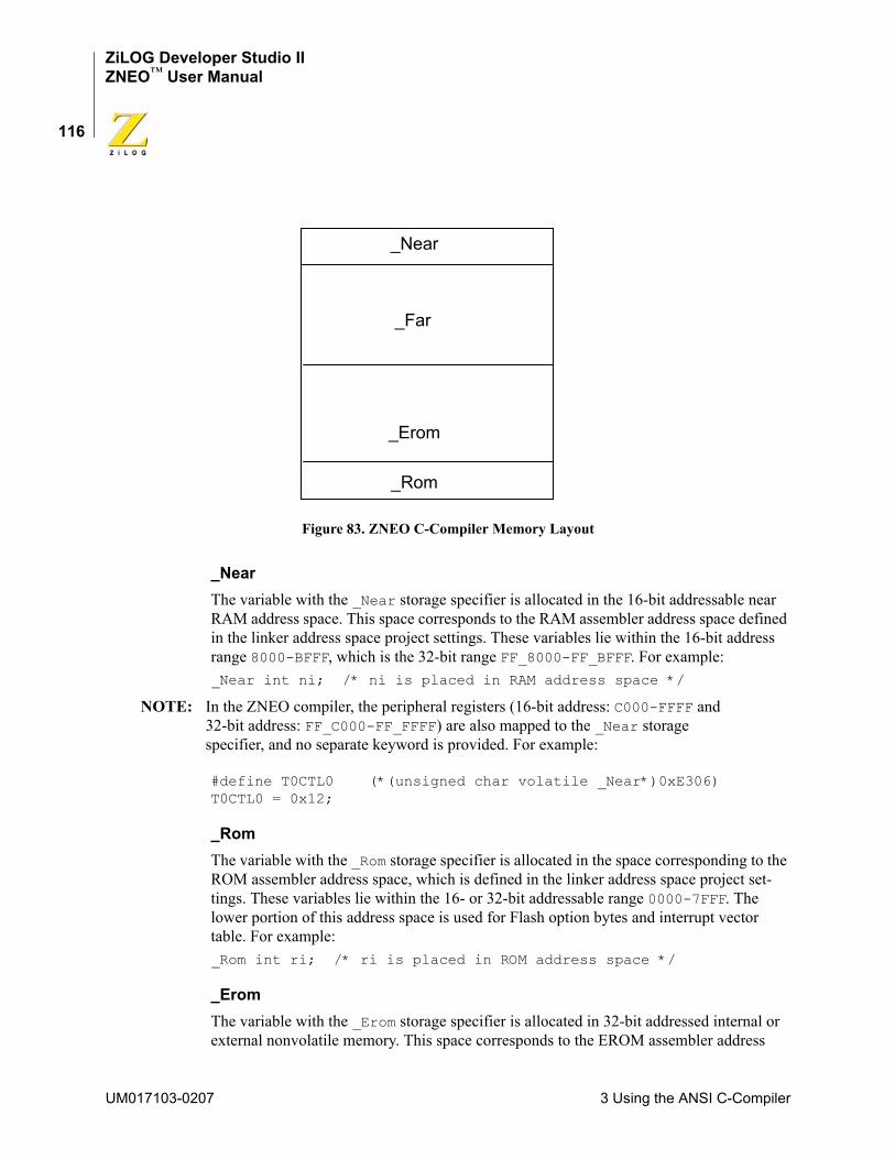
ZiLOG Developer Studio IIZNEO™ User Manual
116
Figure 83. ZNEO C-Compiler Memory Layout
_NearThe variable with the _Near storage specifier is allocated in the 16-bit addressable near RAM address space. This space corresponds to the RAM assembler address space defined in the linker address space project settings. These variables lie within the 16-bit address range 8000-BFFF, which is the 32-bit range FF_8000-FF_BFFF. For example:_Near int ni; /* ni is placed in RAM address space */
NOTE: In the ZNEO compiler, the peripheral registers (16-bit address: C000-FFFF and 32-bit address: FF_C000-FF_FFFF) are also mapped to the _Near storage specifier, and no separate keyword is provided. For example:
#define T0CTL0 (*(unsigned char volatile _Near*)0xE306)T0CTL0 = 0x12;
_RomThe variable with the _Rom storage specifier is allocated in the space corresponding to the ROM assembler address space, which is defined in the linker address space project set-tings. These variables lie within the 16- or 32-bit addressable range 0000-7FFF. The lower portion of this address space is used for Flash option bytes and interrupt vector table. For example:_Rom int ri; /* ri is placed in ROM address space */
_EromThe variable with the _Erom storage specifier is allocated in 32-bit addressed internal or external nonvolatile memory. This space corresponds to the EROM assembler address
_Far
_Near
_Erom
_Rom
UM017103-0207 3 Using the ANSI C-Compiler
ZiLOG Developer Studio IIZNEO™ User Manual
117
space defined in the linker address space project settings. These variables lie within the range extending from 00_8000 to the highest nonvolatile memory address. For example: _Erom int eri; /* eri is placed in EROM address space */
_FarThe variable with the _Far storage specifier is allocated in 32-bit addressed external vola-tile (random access) memory. This space corresponds to the ERAM assembler address space defined in the linker address space project settings. These variables lie within the 32-bit addressed range above the highest EROM address and below FF_8000. For exam-ple:_Far int fi; /* fi is placed in ERAM address space */
Storage Specification for PointersTo properly access _Near, _Far, _Rom, and _Erom objects using a pointer, the compiler provides the ability to associate the storage specifier with the pointer type.
• _Near pointer
The _Near pointer points to _Near data.
• _Far pointer
The _Far pointer points to _Far data.
• _Rom pointer
The _Rom pointer points to _Rom data.
• _Erom pointer
The _Erom pointer points to _Erom data.
For examplechar _Near * _Far npf; // npf is a pointer to a _Near char, npf itself is stored in _Far memory.
Default Storage SpecifiersDefault storage specifiers are applied if none is specified. The default storage specifiers depend on the memory model chosen. See Table 1 for the default storage specifiers for each model type.
Table 1. Default Storage Specifiers
Function Globals Locals String Const Parameters Pointer
Small (S) _Erom _Near _Near _Near _Near _Near _Near
Large (L) _Erom _Far _Far _Far _Far _Far _Far
3 Using the ANSI C-Compiler UM017103-0207
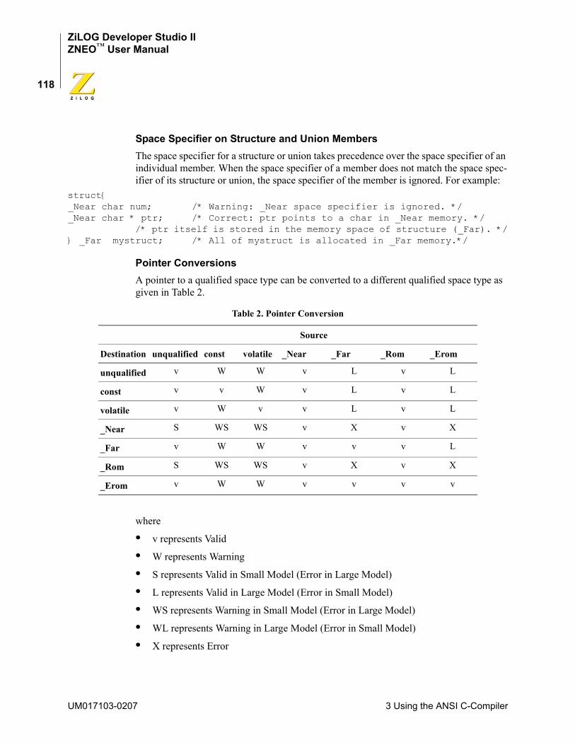
ZiLOG Developer Studio IIZNEO™ User Manual
118
Space Specifier on Structure and Union MembersThe space specifier for a structure or union takes precedence over the space specifier of an individual member. When the space specifier of a member does not match the space spec-ifier of its structure or union, the space specifier of the member is ignored. For example:
struct{_Near char num; /* Warning: _Near space specifier is ignored. */_Near char * ptr; /* Correct: ptr points to a char in _Near memory. */ /* ptr itself is stored in the memory space of structure (_Far). */} _Far mystruct; /* All of mystruct is allocated in _Far memory.*/
Pointer ConversionsA pointer to a qualified space type can be converted to a different qualified space type as given in Table 2.
where
• v represents Valid
• W represents Warning
• S represents Valid in Small Model (Error in Large Model)
• L represents Valid in Large Model (Error in Small Model)
• WS represents Warning in Small Model (Error in Large Model)
• WL represents Warning in Large Model (Error in Small Model)
• X represents Error
Table 2. Pointer Conversion
Source
Destination unqualified const volatile _Near _Far _Rom _Erom
unqualified v W W v L v L
const v v W v L v L
volatile v W v v L v L
_Near S WS WS v X v X
_Far v W W v v v L
_Rom S WS WS v X v X
_Erom v W W v v v v
UM017103-0207 3 Using the ANSI C-Compiler

ZiLOG Developer Studio IIZNEO™ User Manual
119
Memory ModelsThe ZNEO C-Compiler provides two memory models:
• Small memory model
In the small memory model, global variables are allocated in RAM address space. The address of these variables is 16 bits. The locals and parameters are allocated on the stack which is located in RAM address space. The address of a local or parameter is a 16-bit address. The global variables can be manually placed into the ERAM, ROM, or EROM address space by using the _Far, _Rom, and _Erom address specifiers, respectively. The local variables (nonstatic) and parameters are always allocated in RAM address space, and any address specifiers, if used on them, are ignored.
Use of the small memory model does not impose any restriction on your code size. The limitations of the small model are due to the somewhat limited amount of 16-bit addressable RAM. Current ZNEO CPU parts offer up to 4KB of internal RAM, and the ZDS II GUI restricts the total RAM linker address space (internal and external) to 16KB. If the local data and parameters exceed the available RAM size, then the small memory model cannot be used. If the local data and parameters are within the RAM size, but along with global data they exceed the RAM size, then the small model can still be used but only by selectively placing the global data in the extended RAM (ERAM) address space using the _Far keyword. Because ERAM is always located in external memory, this solution requires adding external memory to your system.
• Large memory model
In the large memory model, global variables are allocated in the ERAM address space. The address of these variables is 32 bits. The locals and parameters are allocated on stack, which is located in ERAM address space. The address of a local or parameter is a 32-bit address. The global variables can be manually placed into the RAM, ROM, or EROM address space by using the _Near, _Rom, and _Erom address specifiers, respectively. The local variables (nonstatic) and parameters are always allocated in the ERAM address space, and any address specifiers, if used on them, are ignored.
In the large memory model, the local and global data and parameters can span the entire ERAM space, which can be configured at the user’s discretion to be much larger than the space available in the RAM address space. Besides the requirement to implement an external memory interface, the costs of using the large model are that 32-bit addressing is required to access the variables in ERAM, causing an increase in code size. Also, pointers to these data are 32 bits, which might increase the data space requirements if the application uses lots of pointers. It is possible that the application might run more slowly if accesses to external memory require wait states. To reduce the impact of some of these issues, you can selectively place your more frequently accessed global and static data in RAM using the _Near keyword.
3 Using the ANSI C-Compiler UM017103-0207
ZiLOG Developer Studio IIZNEO™ User Manual
120
Interrupt SupportTo support interrupts, the ZNEO C-Compiler provides two features:
• “interrupt Keyword” on page 120
• “Interrupt Vector Setup” on page 120
interrupt KeywordFunctions that are preceded by #pragma interrupt or are associated with interrupt storage class are designated as interrupt handlers. These functions should neither take parameters nor return a value. The compiler stores the machine state at the beginning of these functions and restores the machine state at the end of these functions. Also, the com-piler uses the iret instruction to return from these functions. For example:void interrupt isr_timer0(void) {}
or #pragma interruptvoid isr_timer0(void){}
Interrupt Vector SetupThe compiler provides an intrinsic function SET_VECTOR for interrupt vector setup. SET_VECTOR can be used to specify the address of an interrupt handler for an interrupt vector. Because the interrupt vectors of the ZNEO microcontroller are usually in ROM, they cannot be modified at run time. The SET_VECTOR function works by switching to a special segment and placing the address of the interrupt handler in the vector table. No executable code is generated for this statement.
The following is the SET_VECTOR intrinsic function prototype:intrinsic void SET_VECTOR(int vectnum,void (*hndlr)(void));
An example of the use of SET_VECTOR is as follows:#include <zneo.h>extern void interrupt isr_timer0(void);void main(void) { SET_VECTOR(TIMER0, isr_timer0);}
UM017103-0207 3 Using the ANSI C-Compiler
ZiLOG Developer Studio IIZNEO™ User Manual
121
The following values for vectnum are supported:
Placement DirectivesThe ZNEO C-Compiler provides language extensions to declare a variable at an address and to align a variable at a specified alignment.
Placement of a VariableThe following syntax can be used to declare a global or static variable at an address:
char placed_char _At 0xb9ff; // placed_char is assigned an address 0xb9ff.far struct {
char ch;int ii;
} ss _At 0x080eff; // ss is assigned an address 0x080eff
rom char init_char _At 0x2fff = 33; // init_char is in rom and initialized to 33
NOTE: Only placed variables with the rom or erom storage class specifiers can be initialized. The placed variables with near and far storage class specifier cannot be initialized. The uninitialized placed variables are not initialized to zero by the compiler startup routine.
Placement of Consecutive VariablesThe compiler also provides syntax to place several variables at consecutive addresses. For example:char ch1 _At 0xbef0;char ch2 _At …; char ch3 _At …;
ADCC0C1C2C3I2CP0ADP1ADP2ADP3ADP4ADP5ADP6AD
P7ADPWM_FAULTPWM_TIMERRESETSPISYSEXCTIMER0TIMER1TIMER2UART0_RXUART0_TXUART1_RXUART1_TX
3 Using the ANSI C-Compiler UM017103-0207
ZiLOG Developer Studio IIZNEO™ User Manual
122
This places ch1 at address 0xbef0, ch2 at the next address (0xbef1) after ch1, and ch3 at the next address (0xbef2) after ch2. The _At … directive can only be used after a pre-vious _At or _Align directive.
Alignment of a VariableThe following syntax can be used to declare a global or static variable aligned at a speci-fied alignment:char ch2 _Align 2; // ch2 is aligned at even boundarychar ch4 _Align 4; // ch4 is aligned at a four byte boundary
NOTE: Only aligned variables with the rom or erom storage class specifiers can be initialized. The aligned variables with the near and far storage class specifiers cannot be initialized. The uninitialized aligned variables are not initialized to zero by the compiler startup routine.
String Placement
When string constants (literals) like "mystring" are used in a C program, they are stored by the C-Compiler in RAM address space for the small memory model and in ERAM address space for the large memory model. However, sometimes this default placement of string constants does not allow you adequate control over your memory usage. Therefore, language extensions are provided to give you more control over string placement:• N"mystring"
This defines a near string constant. The string is stored in RAM. The address of the string is a _Near pointer.
• F"mystring"
This defines a far string constant. The string is stored in ERAM. The address of the string is a _Far pointer.
• R"mystring"
This defines a ROM string constant. The string is stored in ROM. The address of the string is a _Rom pointer.
• E"mystring"
This defines an EROM string constant. The string is stored in EROM. The address of the string is a _Erom pointer.
The following is an example of string placement:#include <sio.h>void funcn (_Near char *str){ while (*str) putch (*str++); putch ('\n');
UM017103-0207 3 Using the ANSI C-Compiler
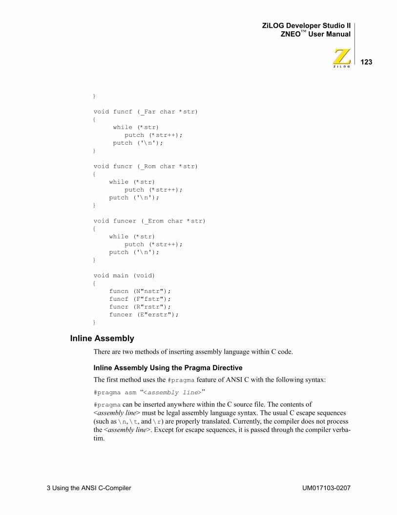
ZiLOG Developer Studio IIZNEO™ User Manual
123
}
void funcf (_Far char *str){ while (*str) putch (*str++); putch ('\n');}
void funcr (_Rom char *str){ while (*str) putch (*str++); putch ('\n');}
void funcer (_Erom char *str){ while (*str) putch (*str++); putch ('\n');}
void main (void){ funcn (N"nstr"); funcf (F"fstr"); funcr (R"rstr"); funcer (E"erstr");}
Inline AssemblyThere are two methods of inserting assembly language within C code.
Inline Assembly Using the Pragma DirectiveThe first method uses the #pragma feature of ANSI C with the following syntax:
#pragma asm “<assembly line>”
#pragma can be inserted anywhere within the C source file. The contents of <assembly line> must be legal assembly language syntax. The usual C escape sequences (such as \n, \t, and \r) are properly translated. Currently, the compiler does not process the <assembly line>. Except for escape sequences, it is passed through the compiler verba-tim.
3 Using the ANSI C-Compiler UM017103-0207
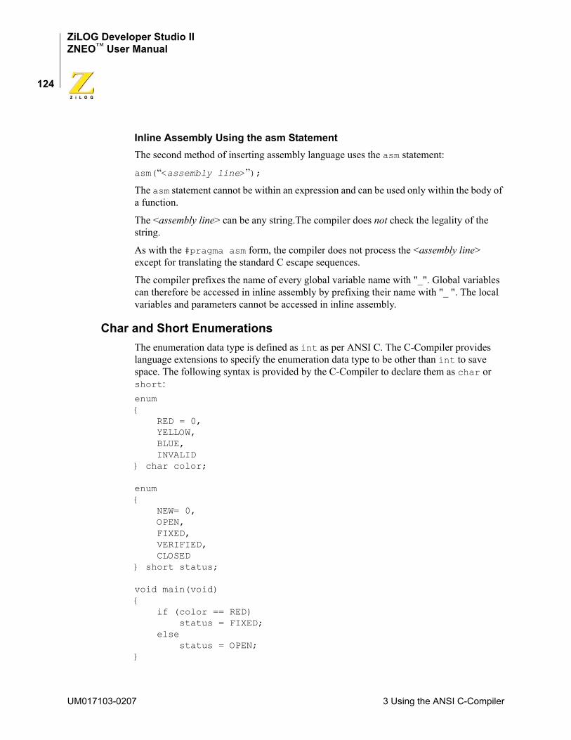
ZiLOG Developer Studio IIZNEO™ User Manual
124
Inline Assembly Using the asm StatementThe second method of inserting assembly language uses the asm statement:
asm(“<assembly line>”);
The asm statement cannot be within an expression and can be used only within the body of a function.
The <assembly line> can be any string.The compiler does not check the legality of the string.
As with the #pragma asm form, the compiler does not process the <assembly line> except for translating the standard C escape sequences.
The compiler prefixes the name of every global variable name with "_". Global variables can therefore be accessed in inline assembly by prefixing their name with "_ ". The local variables and parameters cannot be accessed in inline assembly.
Char and Short EnumerationsThe enumeration data type is defined as int as per ANSI C. The C-Compiler provides language extensions to specify the enumeration data type to be other than int to save space. The following syntax is provided by the C-Compiler to declare them as char or short:enum{ RED = 0, YELLOW, BLUE, INVALID} char color;
enum{ NEW= 0, OPEN, FIXED, VERIFIED, CLOSED} short status;
void main(void){ if (color == RED) status = FIXED; else status = OPEN;}
UM017103-0207 3 Using the ANSI C-Compiler
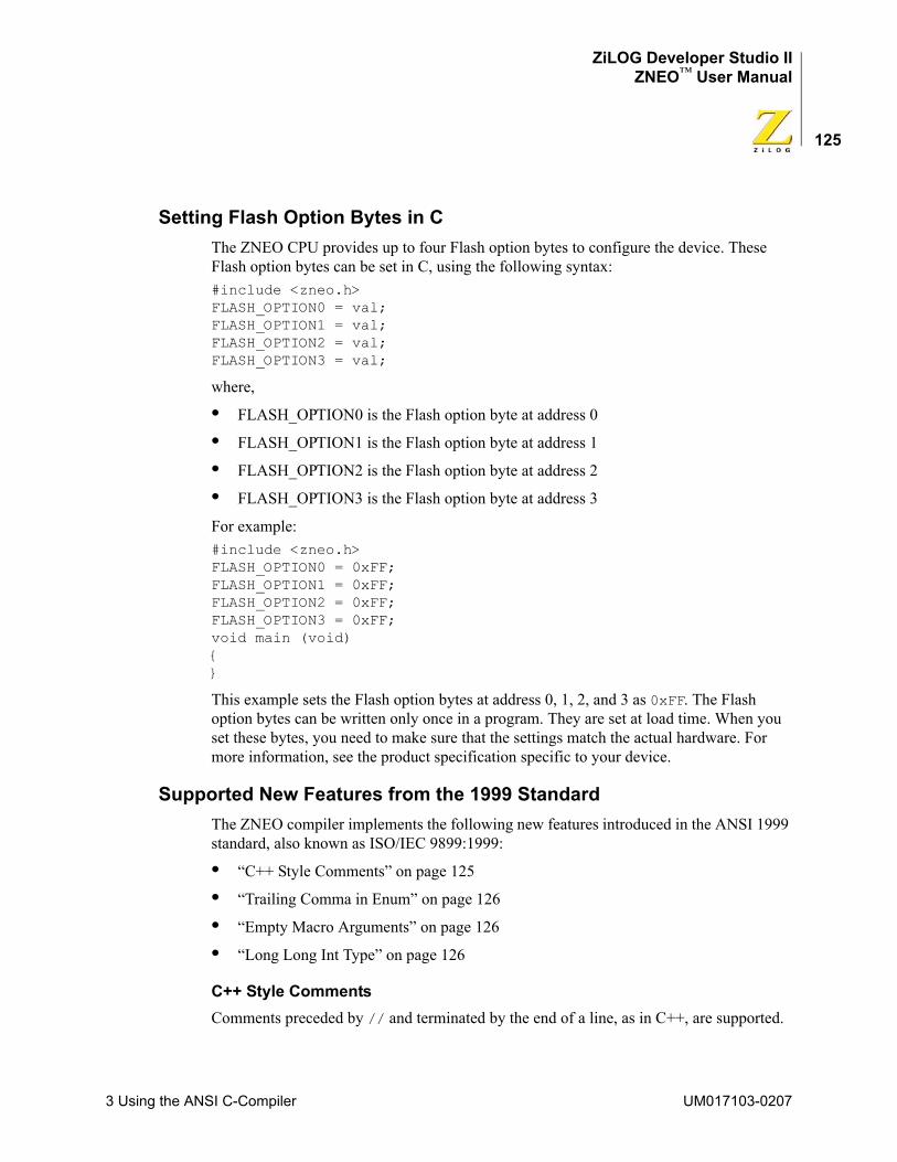
ZiLOG Developer Studio IIZNEO™ User Manual
125
Setting Flash Option Bytes in CThe ZNEO CPU provides up to four Flash option bytes to configure the device. These Flash option bytes can be set in C, using the following syntax:#include <zneo.h>FLASH_OPTION0 = val;FLASH_OPTION1 = val;FLASH_OPTION2 = val;FLASH_OPTION3 = val;
where,
• FLASH_OPTION0 is the Flash option byte at address 0
• FLASH_OPTION1 is the Flash option byte at address 1
• FLASH_OPTION2 is the Flash option byte at address 2
• FLASH_OPTION3 is the Flash option byte at address 3
For example:#include <zneo.h>FLASH_OPTION0 = 0xFF;FLASH_OPTION1 = 0xFF;FLASH_OPTION2 = 0xFF;FLASH_OPTION3 = 0xFF;void main (void){}
This example sets the Flash option bytes at address 0, 1, 2, and 3 as 0xFF. The Flash option bytes can be written only once in a program. They are set at load time. When you set these bytes, you need to make sure that the settings match the actual hardware. For more information, see the product specification specific to your device.
Supported New Features from the 1999 StandardThe ZNEO compiler implements the following new features introduced in the ANSI 1999 standard, also known as ISO/IEC 9899:1999:
• “C++ Style Comments” on page 125
• “Trailing Comma in Enum” on page 126
• “Empty Macro Arguments” on page 126
• “Long Long Int Type” on page 126
C++ Style CommentsComments preceded by // and terminated by the end of a line, as in C++, are supported.
3 Using the ANSI C-Compiler UM017103-0207
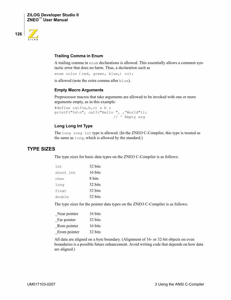
ZiLOG Developer Studio IIZNEO™ User Manual
126
Trailing Comma in EnumA trailing comma in enum declarations is allowed. This essentially allows a common syn-tactic error that does no harm. Thus, a declaration such asenum color {red, green, blue,} col;
is allowed (note the extra comma after blue).
Empty Macro ArgumentsPreprocessor macros that take arguments are allowed to be invoked with one or more arguments empty, as in this example:#define cat3(a,b,c) a b cprintf("%s\n", cat3("Hello ", ,”World"));
// ^ Empty arg
Long Long Int TypeThe long long int type is allowed. (In the ZNEO C-Compiler, this type is treated as the same as long, which is allowed by the standard.)
TYPE SIZESThe type sizes for basic data types on the ZNEO C-Compiler is as follows:
The type sizes for the pointer data types on the ZNEO C-Compiler is as follows:
All data are aligned on a byte boundary. (Alignment of 16- or 32-bit objects on even boundaries is a possible future enhancement. Avoid writing code that depends on how data are aligned.)
int 32 bitsshort int 16 bitschar 8 bitslong 32 bitsfloat 32 bitsdouble 32 bits
_Near pointer 16 bits_Far pointer 32 bits_Rom pointer 16 bits_Erom pointer 32 bits
UM017103-0207 3 Using the ANSI C-Compiler
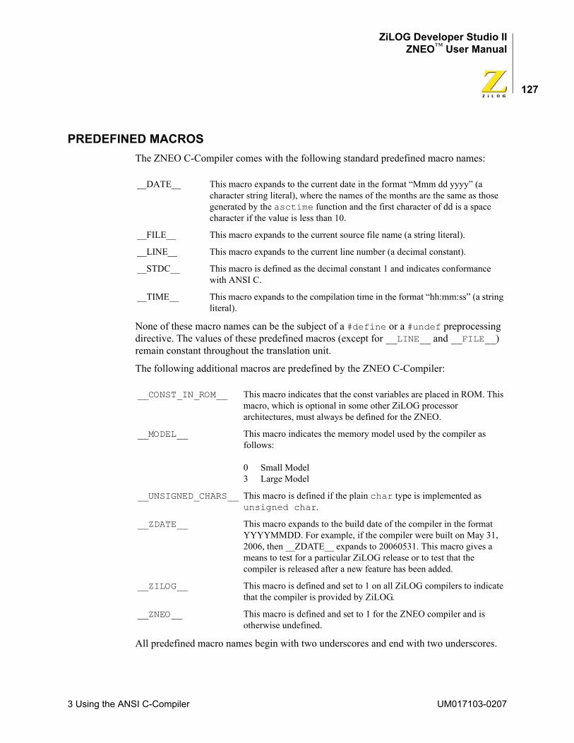
ZiLOG Developer Studio IIZNEO™ User Manual
127
PREDEFINED MACROS The ZNEO C-Compiler comes with the following standard predefined macro names:
None of these macro names can be the subject of a #define or a #undef preprocessing directive. The values of these predefined macros (except for __LINE__ and __FILE__) remain constant throughout the translation unit.
The following additional macros are predefined by the ZNEO C-Compiler:
All predefined macro names begin with two underscores and end with two underscores.
__DATE__ This macro expands to the current date in the format “Mmm dd yyyy” (a character string literal), where the names of the months are the same as those generated by the asctime function and the first character of dd is a space character if the value is less than 10.
__FILE__ This macro expands to the current source file name (a string literal).
__LINE__ This macro expands to the current line number (a decimal constant).
__STDC__ This macro is defined as the decimal constant 1 and indicates conformance with ANSI C.
__TIME__ This macro expands to the compilation time in the format “hh:mm:ss” (a string literal).
__CONST_IN_ROM__ This macro indicates that the const variables are placed in ROM. This macro, which is optional in some other ZiLOG processor architectures, must always be defined for the ZNEO.
__MODEL__ This macro indicates the memory model used by the compiler as follows:
0 Small Model3 Large Model
__UNSIGNED_CHARS__ This macro is defined if the plain char type is implemented as unsigned char.
__ZDATE__ This macro expands to the build date of the compiler in the format YYYYMMDD. For example, if the compiler were built on May 31, 2006, then __ZDATE__ expands to 20060531. This macro gives a means to test for a particular ZiLOG release or to test that the compiler is released after a new feature has been added.
__ZILOG__ This macro is defined and set to 1 on all ZiLOG compilers to indicate that the compiler is provided by ZiLOG.
__ZNEO__ This macro is defined and set to 1 for the ZNEO compiler and is otherwise undefined.
3 Using the ANSI C-Compiler UM017103-0207
ZiLOG Developer Studio IIZNEO™ User Manual
128
ExamplesThe following program illustrates the use of some of these predefined macros:#include <stdio.h>void main(){#ifdef __ZILOG__ printf("ZiLOG Compiler ");#endif#ifdef __ZNEO__ printf("For ZNEO ");#endif#ifdef __ZDATE__ printf("Built on %d.\n", __ZDATE__);#endif}
CALLING CONVENTIONSThe C-Compiler imposes a strict set of rules on function calls. Except for special run-time support functions, any function that calls or is called by a C function must follow these rules. Failure to adhere to these rules can disrupt the C environment and cause a C pro-gram to fail.
Function Call MechanismA function (caller function) performs the following tasks when it calls another function (called function):
1. Save any of the registers R0-R7 that are in use and may be needed after the call; these registers may be overwritten in the called function.
2. Place the first seven scalar parameters (not structures or unions) of the called function in registers R1–R7. Push parameters beyond the seventh parameter and nonscalar parameters on the stack in reverse order (the rightmost declared argument is pushed first, and the leftmost is pushed last). This places the leftmost argument on top of the stack when the function is called. For a varargs function, all parameters are pushed on the stack in reverse order.
3. Then call the function. The call instruction pushes the return address on the top of the stack.
4. On return from the called function, caller pops the arguments off the stack or increment the stack pointer.
5. Restore any of the registers R0–R7 that were saved in step 1.
When a byte or structure of an odd size is pushed on the stack, only the byte or structure is pushed. Future enhancements might introduce padding so that 16- or 32-bit objects are
UM017103-0207 3 Using the ANSI C-Compiler

ZiLOG Developer Studio IIZNEO™ User Manual
129
located at an even offset from the frame pointer so avoid writing code that depends on the alignment of data. If you are writing an assembly routine called out of C, it is recom-mended that you declare parameters as short rather than char so that offsets to parame-ters are not changed by such an enhancement.
The called function performs the following tasks:
1. Push the frame pointer onto the stack and allocate the local frame:
a. Set the frame pointer to the current value of the stack pointer.
b. Decrement the stack pointer by the size of locals and temporaries, if required.
2. Save the contents of any of the registers R8–R13 (and possibly R14; see comment below) that are going to be used inside this function.
3. Execute the code for the function.
4. Restore any of the registers R8–R14 that were saved in step 2.
5. If the function returns a scalar value, place it in the r0 register. For functions returning an aggregate, see “Special Cases” on page 130.
6. Deallocate the local frame (set the stack pointer to the current value of frame pointer) and restore the frame pointer from stack.
7. Return.
Registers R8–R13 are considered as “callee” save, that is, they are saved and restored (if necessary) by the called function. If the called function does not set up a frame pointer, it can also use R14 as a general-purpose register, but must still save it on entry and restore it on exit. The flag register is not saved and restored by the called function.
The function call mechanism described in this section is a dynamic call mechanism. In a dynamic call mechanism, each function allocates memory on stack for its locals and tem-poraries during the run time of the program. When the function has returned, the memory that it was using is freed from the stack. Figure 84 shows a diagram of the ZNEO C-Com-piler dynamic call frame layout.
3 Using the ANSI C-Compiler UM017103-0207
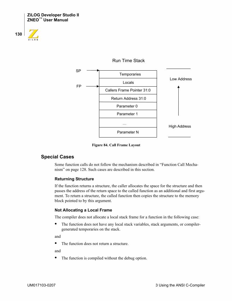
ZiLOG Developer Studio IIZNEO™ User Manual
130
Figure 84. Call Frame Layout
Special CasesSome function calls do not follow the mechanism described in “Function Call Mecha-nism” on page 128. Such cases are described in this section.
Returning StructureIf the function returns a structure, the caller allocates the space for the structure and then passes the address of the return space to the called function as an additional and first argu-ment. To return a structure, the called function then copies the structure to the memory block pointed to by this argument.
Not Allocating a Local FrameThe compiler does not allocate a local stack frame for a function in the following case:
• The function does not have any local stack variables, stack arguments, or compiler-generated temporaries on the stack.
and
• The function does not return a structure.
and
• The function is compiled without the debug option.
Temporaries
Locals
Callers Frame Pointer 31:0
Return Address 31:0
Parameter 0
Parameter 1
…
Parameter N
FP
SP
Run Time Stack
High Address
Low Address
UM017103-0207 3 Using the ANSI C-Compiler
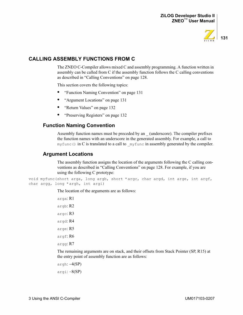
ZiLOG Developer Studio IIZNEO™ User Manual
131
CALLING ASSEMBLY FUNCTIONS FROM CThe ZNEO C-Compiler allows mixed C and assembly programming. A function written in assembly can be called from C if the assembly function follows the C calling conventions as described in “Calling Conventions” on page 128.
This section covers the following topics:
• “Function Naming Convention” on page 131
• “Argument Locations” on page 131
• “Return Values” on page 132
• “Preserving Registers” on page 132
Function Naming ConventionAssembly function names must be preceded by an _ (underscore). The compiler prefixes the function names with an underscore in the generated assembly. For example, a call to myfunc() in C is translated to a call to _myfunc in assembly generated by the compiler.
Argument LocationsThe assembly function assigns the location of the arguments following the C calling con-ventions as described in “Calling Conventions” on page 128. For example, if you are using the following C prototype:
void myfunc(short arga, long argb, short *argc, char argd, int arge, int argf, char argg, long *argh, int argi)
The location of the arguments are as follows:
arga: R1
argb: R2
argc: R3
argd: R4
arge: R5
argf: R6
argg: R7
The remaining arguments are on stack, and their offsets from Stack Pointer (SP, R15) at the entry point of assembly function are as follows:
argh: -4(SP)
argi: -8(SP)
3 Using the ANSI C-Compiler UM017103-0207
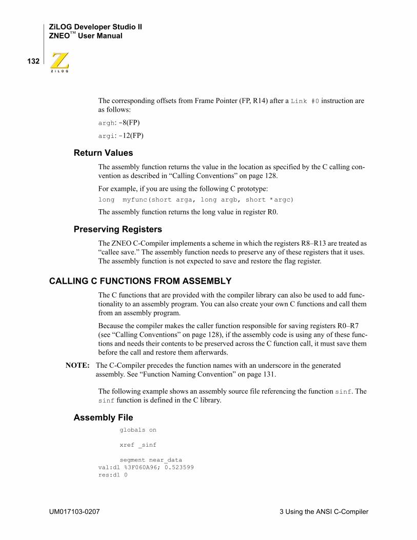
ZiLOG Developer Studio IIZNEO™ User Manual
132
The corresponding offsets from Frame Pointer (FP, R14) after a Link #0 instruction are as follows:
argh: -8(FP)
argi: -12(FP)
Return ValuesThe assembly function returns the value in the location as specified by the C calling con-vention as described in “Calling Conventions” on page 128.
For example, if you are using the following C prototype:long myfunc(short arga, long argb, short *argc)
The assembly function returns the long value in register R0.
Preserving RegistersThe ZNEO C-Compiler implements a scheme in which the registers R8–R13 are treated as “callee save.” The assembly function needs to preserve any of these registers that it uses. The assembly function is not expected to save and restore the flag register.
CALLING C FUNCTIONS FROM ASSEMBLYThe C functions that are provided with the compiler library can also be used to add func-tionality to an assembly program. You can also create your own C functions and call them from an assembly program.
Because the compiler makes the caller function responsible for saving registers R0–R7 (see “Calling Conventions” on page 128), if the assembly code is using any of these func-tions and needs their contents to be preserved across the C function call, it must save them before the call and restore them afterwards.
NOTE: The C-Compiler precedes the function names with an underscore in the generated assembly. See “Function Naming Convention” on page 131.
The following example shows an assembly source file referencing the function sinf. The sinf function is defined in the C library.
Assembly Fileglobals on
xref _sinf
segment near_dataval:dl %3F060A96; 0.523599res:dl 0
UM017103-0207 3 Using the ANSI C-Compiler
ZiLOG Developer Studio IIZNEO™ User Manual
133
segment code_main:
pushm <R1>; save the registers, other than return register, if any in use
ld R1,val ; load the argumentcall _sinf ; call the c functionsld res,r0 ; the result is in r0
popm <R1> ; restore the registers, if any were saved
ret
Referenced C Function Prototypefloat sinf(float arg);
COMMAND LINE OPTIONSThe compiler, like the other tools in ZDS II, can be run from the command line for pro-cessing inside a script, and so on. Please see “Compiler Command Line Options” on page 301 for the list of compiler commands that are available from the command line.
RUN-TIME LIBRARYThe C-Compiler provides a collection of run-time libraries. The largest section of these libraries consists of an implementation of much of the C Standard Library. A small library of functions specific to ZiLOG or to the ZNEO is also provided.
The ZNEO C-Compiler is a conforming freestanding 1989 ANSI C implementation with some exceptions. In accordance with the definition of a freestanding implementation, the compiler supports the required standard header files <float.h>, <limits.h>, <stdarg.h>, and <stddef.h>. It also supports additional standard header files and ZiLOG-specific nonstandard header files.
The standard header files and functions are, with minor exceptions, fully compliant with the ANSI C Standard. They are described in detail in the “C Standard Library” appendix on page 337. The deviations from the ANSI Standard in these files are summarized in “Library Files Not Required for Freestanding Implementation” on page 151. The follow-ing sections describe the use and format of the nonstandard, ZiLOG-specific run-time libraries:
• “ZiLOG Header Files” on page 134
• “ZiLOG Functions” on page 136
The ZiLOG-specific header files provided with the compiler are listed in Table 3 and described in “ZiLOG Header Files” on page 134.
3 Using the ANSI C-Compiler UM017103-0207
ZiLOG Developer Studio IIZNEO™ User Manual
134
NOTE: The ZiLOG-specific header files are located in the following directory:
<ZDS Installation Directory>\include\zilog
where <ZDS Installation Directory> is the directory in which ZiLOG Developer Studio was installed. By default, this would be C:\Program Files\ZiLOG\ZDSII_ZNEO_<version>, where <version> might be 4.11.0 or 5.0.0.
NOTE: All external identifiers declared in any of the headers are reserved, whether or not the associated header is included. All external identifiers and macro names that begin with an underscore are also reserved. If the program redefines a reserved external identifier, even with a semantically equivalent form, the behavior is indeterminate.
ZiLOG Header Files
Architecture-Specific Functions <zneo.h>A ZNEO-specific header file <zneo.h> is provided that has prototypes for ZiLOG- specific C library functions and macro definitions.
Macros
<zneo.h> has macro definitions giving the more conventional names for storage specifi-ers:
<zneo.h> has the macro definitions for all ZNEO microcontroller peripheral registers. For example:
Refer to the ZNEO product specifications for the list of peripheral registers supported.
Table 3. Nonstandard Headers
Header Description Page
<zneo.h> ZNEO defines and functions page 134
<sio.h> Serial input/output functions page 135
erom Expands to space specifier _Erom.near Expands to space specifier _Near.far Expands to space specifier _Far.rom Expands to space specifier _Rom.
T0H Expands to (*(unsigned char volatile near*)0xE300)
UM017103-0207 3 Using the ANSI C-Compiler
ZiLOG Developer Studio IIZNEO™ User Manual
135
<zneo.h> also has the macro definition for the ZNEO Flash option bytes:
<zneo.h> also has the macro definition for interrupt vector addresses:
Refer to the ZNEO product specifications for the list of interrupt vectors supported.
Functions
Nonstandard I/O Functions <sio.h>This header contains nonstandard ZNEO-specific input/output functions.
FLASH_OPTION0 Expands to a _Rom char at address 0x0.FLASH_OPTION1 Expands to a _Rom char at address 0x1.FLASH_OPTION2 Expands to a _Rom char at address 0x2.FLASH_OPTION3 Expands to a _Rom char at address 0x3.
RESET Expands to address of Reset vector.
intrinsic void EI(void); Enable interrupts.intrinsic void DI(void); Disable interrupts.intrinsic void RI(unsigned short istat); Restores interrupts.intrinsic void SET_VECTOR(int vectnum,void (*hndlr)(void)); Specifies the address of an
interrupt handler for an interrupt vector.
intrinsic unsigned short TDI(void); Tests and disables interrupts.
_DEFFREQ Expands to unsigned long default frequency._DEFBAUD Expands to unsigned long default baud rate._UART0 Expands to an integer indicating UART0._UART1 Expands to an integer indicating UART1.
3 Using the ANSI C-Compiler UM017103-0207
ZiLOG Developer Studio IIZNEO™ User Manual
136
Functions
ZiLOG FunctionsThe following functions are ZiLOG specific:
• “DI” on page 136
• “EI” on page 137
• “getch” on page 137
• “init_uart” on page 137
• “kbhit” on page 138
• “putch” on page 138
• “RI” on page 139
• “select_port” on page 139
• “SET_VECTOR” on page 140
• “TDI” on page 141
DIDI is a ZiLOG intrinsic function that disables all interrupts. This function is an intrinsic function and is inline expanded by default. If the –reduceopt compiler option is selected, then this function is not inline expanded and is implemented as a regular function instead.
Synopsis
#include <zneo.h> intrinsic void DI(void);
Example
#include <zneo.h>
char getch( void ) ; Returns the data byte available in the selected UART.
int init_uart(int port,unsigned long freq, unsigned long baud); Initializes the selected UART for specified settings and returns the error status.
int kbhit(void); Checks for receive data available on selected UART.
int putch( char ) ; Sends a character to the selected UART and returns the error status.
int select_port(int port); Selects the UART. Default is _UART0.
UM017103-0207 3 Using the ANSI C-Compiler
ZiLOG Developer Studio IIZNEO™ User Manual
137
void main(void){
DI(); /* Disable interrupts */}
EIEI is a ZiLOG intrinsic function that enables all interrupts. This function is an intrinsic function and is inline expanded by default. If the –reduceopt compiler option is selected, then this function is not inline expanded and is implemented as a regular function instead.
Synopsis
#include <zneo.h> intrinsic void EI(void);
Example
#include <zneo.h>
void main(void){
EI(); /* Enable interrupts */}
getchgetch is a ZILOG function that waits for the next character to appear at the serial port and returns its value. This function does not wait for end-of-line to return as getchar does. getch does not echo the character received.
Synopsis
#include <sio.h>char getch(void) ;
Returns
The next character that is received at the selected UART.
Example
char ch;ch=getch();
NOTE: Before using this function, the init_uart() function needs to be called to initialize and select the UART. The default UART is _UART0.
init_uartThe init_uart function is a ZiLOG function that selects the specified UART and initial-izes it for specified settings and returns the error status.
3 Using the ANSI C-Compiler UM017103-0207
ZiLOG Developer Studio IIZNEO™ User Manual
138
Synopsis
#include <sio.h> int init_uart(int port, unsigned long freq, unsigned long baud);
Returns
Returns 0 if initialization is successful and 1 otherwise.
Example
#include <stdio.h>#include <sio.h> void main(){
init_uart(_UART0,_DEFFREQ,_DEFBAUD); printf("Hello UART0\n"); // Write to _UART0
}
_DEFFREQ is automatically set from the IDE using the setting in the Configure Target dialog box. See “Setup” on page 82.
kbhitkbhit is a ZiLOG function that determines whether there is receive data available on the selected UART.
Synopsis
#include <sio.h> int kbhit(void);
Returns
Returns 1 if there is receive data available on the selected UART; otherwise, it returns 0.
Example
int i; i=kbhit();
NOTE: Before using this function, the init_uart() function needs to be called to initialize and select the UART. The default UART is _UART0.
putchputch is a ZiLOG function that sends a character to the selected UART and returns the error status.
Synopsis
#include <sio.h>int putch( char ch ) ;
UM017103-0207 3 Using the ANSI C-Compiler
ZiLOG Developer Studio IIZNEO™ User Manual
139
Returns
A zero is returned on success; a nonzero is returned on failure.
Example
char ch = 'c' ;int err;err = putch( ch ) ;
NOTE: Before using this function, the init_uart() function needs to be called to initialize and select the UART. The default UART is _UART0.
RIRI (restore interrupt) is a ZiLOG intrinsic function that restores interrupt status. It is intended to be paired with an earlier call to TDI(), which has previously saved the exist-ing interrupt status. See “TDI” on page 141 for a discussion of that function. The interrupt status, which is passed as a parameter to RI(), consists of the flags register extended to 16 bits for efficient stack storage. This function is an intrinsic function and is inline expanded by default. If the –reduceopt compiler option is selected, then this function is not inline expanded and is implemented as a regular function instead.
Synopsis
#include <zneo.h>intrinsic void RI(unsigned short istat);
Example
#include <zneo.h>
void main(void){ unsigned short istat; istat = TDI(); /* Test and Disable Interrupts */ /* Do Something */ RI(istat); /* Restore Interrupts */ }
select_portselect_port is a ZiLOG function that selects the UART. The default is _UART0. The init_uart function can be used to configure either _UART0 or _UART1 and select the UART passed as the current one for use. All calls to putch, getch, and kbhit use the selected UART. You can also change the selected UART using the select_port function without having to reinitialize the UART.
Synopsis
#include <sio.h>int select_port( int port ) ;
3 Using the ANSI C-Compiler UM017103-0207
ZiLOG Developer Studio IIZNEO™ User Manual
140
Returns
A zero is returned on success; a nonzero is returned on failure.
Example
#include <stdio.h>#include <sio.h> void main(void){
init_uart(_UART0,_DEFFREQ,_DEFBAUD);init_uart(_UART1,_DEFFREQ,_DEFBAUD);select_port(_UART0);printf("Hello UART0\n"); // Write to uart0select_port(_UART1);printf("Hello UART1\n"); // Write to uart1
}
SET_VECTORSET_VECTOR is a ZiLOG intrinsic function provided by the compiler to specify the address of an interrupt handler for an interrupt vector. Because the interrupt vectors of the ZNEO microcontroller are usually in ROM, they cannot be modified at run time. The SET_VECTOR function works by switching to a special segment and placing the address of the interrupt handler in the vector table. No executable code is generated for this state-ment. Calls to the SET_VECTOR intrinsic function must be placed within a function body. The –reduceopt compiler option does not affect the SET_VECTOR function handling.
Synopsis
#include <zneo.h>intrinsic void SET_VECTOR(int vectnum,void (*hndlr)(void));
where
• vectnum is the interrupt vector number for which the interrupt handler hndlr is to be set.
• hndlr is the interrupt handler function pointer. The hndlr function must be declared to be of the interrupt type with parameters and return as void (no parameters and no return).
UM017103-0207 3 Using the ANSI C-Compiler
ZiLOG Developer Studio IIZNEO™ User Manual
141
The compiler supports the following values for vectnum for ZNEO:
Returns
None
Example
#include <zneo.h>extern void interrupt isr_timer0(void);void main(void){
SET_VECTOR(TIMER0, isr_timer0); /* setup TIMER0 vector */}
TDITDI (test and disable interrupts) is a ZiLOG intrinsic function that supports users creating their own critical sections of code. It returns the previous interrupt status and disables interrupts. It is intended to be paired with a later call to RI(), which will restore the previ-ously existing interrupt status. See “RI” on page 139 for a discussion of that function. The interrupt status, which is returned from TDI(), consists of the flags register extended to 16 bits for efficient stack storage.
This function is an intrinsic function and is inline expanded by default. If the –reduceopt compiler option is selected, then this function is not inline expanded and is implemented as a regular function instead.
Synopsis
#include <zneo.h>intrinsic unsigned short TDI(void);
Example
#include <zneo.h>
ADCC0C1C2C3I2CP0ADP1ADP2ADP3ADP4ADP5ADP6AD
P7ADPWM_FAULTPWM_TIMERRESETSPISYSEXCTIMER0TIMER1TIMER2UART0_RXUART0_TXUART1_RXUART1_TX
3 Using the ANSI C-Compiler UM017103-0207
ZiLOG Developer Studio IIZNEO™ User Manual
142
void main(void){
unsigned short istat; istat = TDI(); /* Test and Disable Interrupts *//* Do Something */RI(istat); /* Restore Interrupts */
}
STACK POINTER OVERFLOWThe run-time library for the ZNEO C-Compiler manipulates the SPOV register to protect program and allocated data. The default action is:
• The SPOV register is initialized to the end of the initialized data segment. So if the Stack Pointer is decremented below SPOV, it results in the Stack overflow exception.
• When malloc() is called, the SPOV register is increased to the highest address of allocated data; malloc() returns NULL if changing the SPOV results in an immediate stack overflow.
• Calling free() returns memory for possible use by malloc() but does not return memory for possible use as stack, that is, the SPOV register is not updated.
• However, if you modify the SPOV register directly, malloc() leaves SPOV where you have put it and does not allocate data on the stack side of SPOV.
The run-time library does not supply a handler for the stack overflow exception (or any other exception). If there is any possibility of your released application overflowing its stack, you need to decide how to recover from the situation and write your own handler.
STARTUP FILESThe startup or C run-time initialization file is an assembly program that performs required start-up functions and then calls main, which is the C entry point. The startup program performs the following C run-time initializations:
• Initialize the stack pointer and stack overflow register.
• Initialize the external interface if enabled. See the description of the Configure Target dialog box on page 82.
• Clear the _Near and _Far uninitialized variables to zero.
• Set the initialized _Near and _Far variables to their initial value from _Erom.
• Allocate space for interrupt vectors.
• Allocate space for the errno variable used by the C run-time libraries.
Table 4 lists the startup files provided with the ZNEO C-Compiler.
UM017103-0207 3 Using the ANSI C-Compiler
ZiLOG Developer Studio IIZNEO™ User Manual
143
SEGMENT NAMINGThe compiler places code and data into separate segments in the object file. The different segments used by the compiler are listed in Table 5.
Table 4. ZNEO Startup Files
Name Description
lib\zilog\startups.obj C startup object file for small model
src\boot\common\startups.asm C startup source file for small model
lib\zilog\startupl.obj C startup object file for large model
src\boot\common\startupl.asm C startup source file for large model
lib\zilog\startupexkl.obj C startup object file (large model) with external interface set up for devices with Port K.
lib\zilog\startupexl.obj C startup object file (large model) with external interface set up for devices without Port K.
src\boot\common\startupexl.asm C startup source file (large model) with external interface set up.
lib\zilog\startupexks.obj C startup object file (small model) with external interface set up for devices with Port K.
lib\zilog\startupexs.obj C startup object file (small model) with external interface set up for devices without Port K.
src\boot\common\startupexs.asm C startup source file (small model) with external interface set up.
Table 5. Segments
Segment Description
NEAR_DATA _Near initialized global and static data
NEAR_BSS _Near un-initialized global and static data
NEAR_TEXT _Near constant strings
FAR_DATA _Far initialized global and static data
FAR_BSS _Far un-initialized global and static data
FAR_TEXT _Far constant strings
3 Using the ANSI C-Compiler UM017103-0207
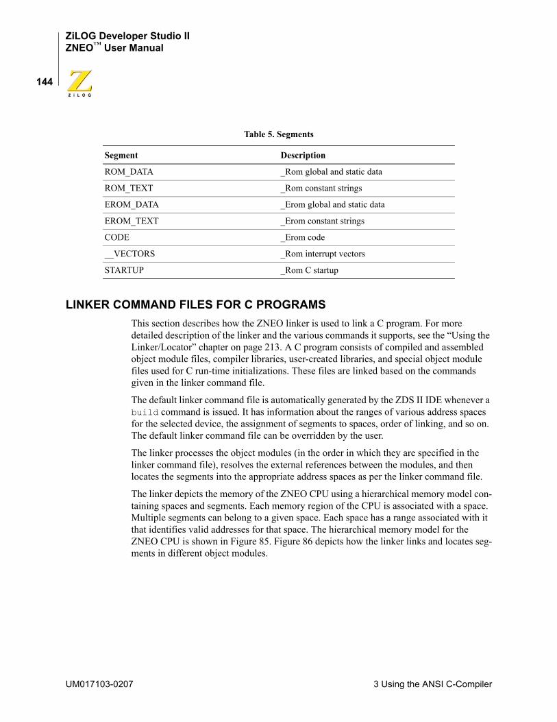
ZiLOG Developer Studio IIZNEO™ User Manual
144
LINKER COMMAND FILES FOR C PROGRAMSThis section describes how the ZNEO linker is used to link a C program. For more detailed description of the linker and the various commands it supports, see the “Using the Linker/Locator” chapter on page 213. A C program consists of compiled and assembled object module files, compiler libraries, user-created libraries, and special object module files used for C run-time initializations. These files are linked based on the commands given in the linker command file.
The default linker command file is automatically generated by the ZDS II IDE whenever a build command is issued. It has information about the ranges of various address spaces for the selected device, the assignment of segments to spaces, order of linking, and so on. The default linker command file can be overridden by the user.
The linker processes the object modules (in the order in which they are specified in the linker command file), resolves the external references between the modules, and then locates the segments into the appropriate address spaces as per the linker command file.
The linker depicts the memory of the ZNEO CPU using a hierarchical memory model con-taining spaces and segments. Each memory region of the CPU is associated with a space. Multiple segments can belong to a given space. Each space has a range associated with it that identifies valid addresses for that space. The hierarchical memory model for the ZNEO CPU is shown in Figure 85. Figure 86 depicts how the linker links and locates seg-ments in different object modules.
ROM_DATA _Rom global and static data
ROM_TEXT _Rom constant strings
EROM_DATA _Erom global and static data
EROM_TEXT _Erom constant strings
CODE _Erom code
__VECTORS _Rom interrupt vectors
STARTUP _Rom C startup
Table 5. Segments
Segment Description
UM017103-0207 3 Using the ANSI C-Compiler
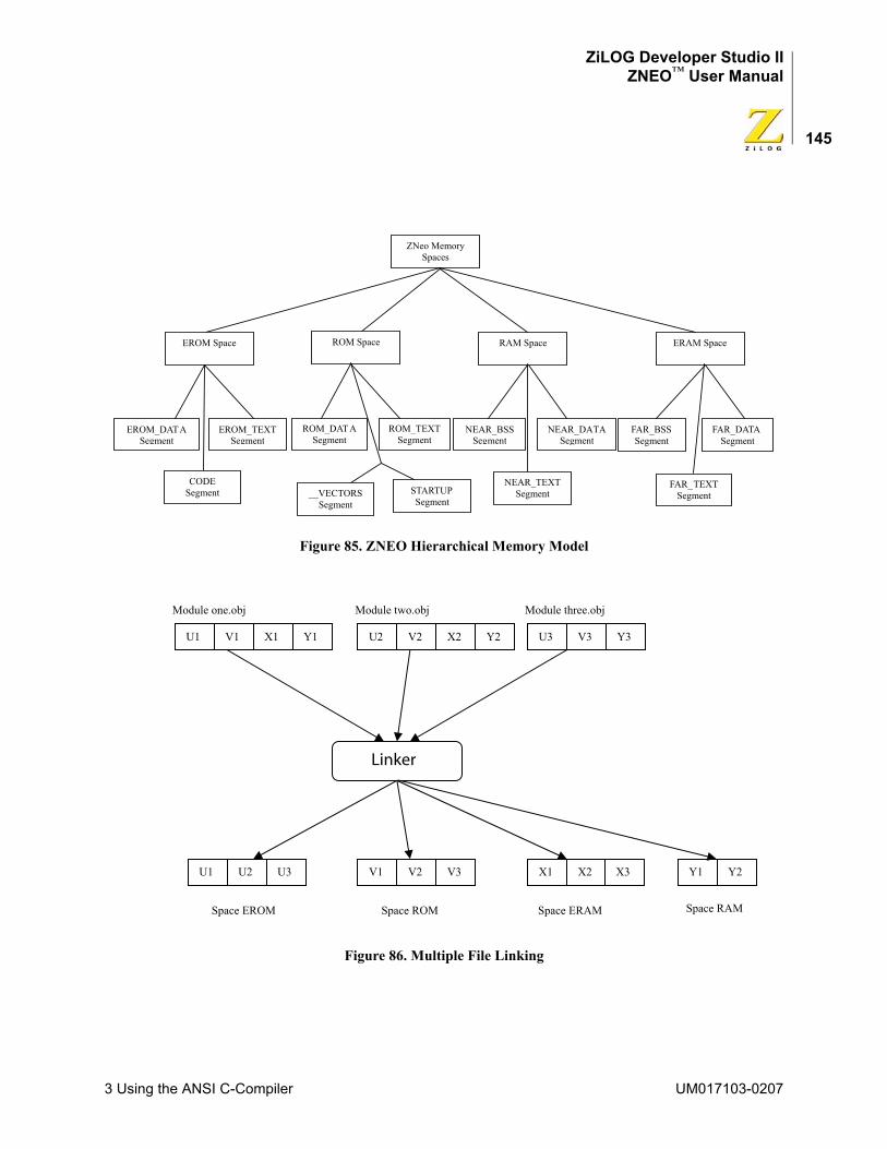
ZiLOG Developer Studio IIZNEO™ User Manual
145
Figure 85. ZNEO Hierarchical Memory Model
Figure 86. Multiple File Linking
U1 V1 X1 U2 X2V2 U3 V3
Linker
U1 V1U3U2 V2 X2X1V3
Module one.obj Module two.obj Module three.obj
Space EROM Space ROM Space ERAM
Y1 Y2 Y3
X3 Y1 Y2
Space RAM
3 Using the ANSI C-Compiler UM017103-0207
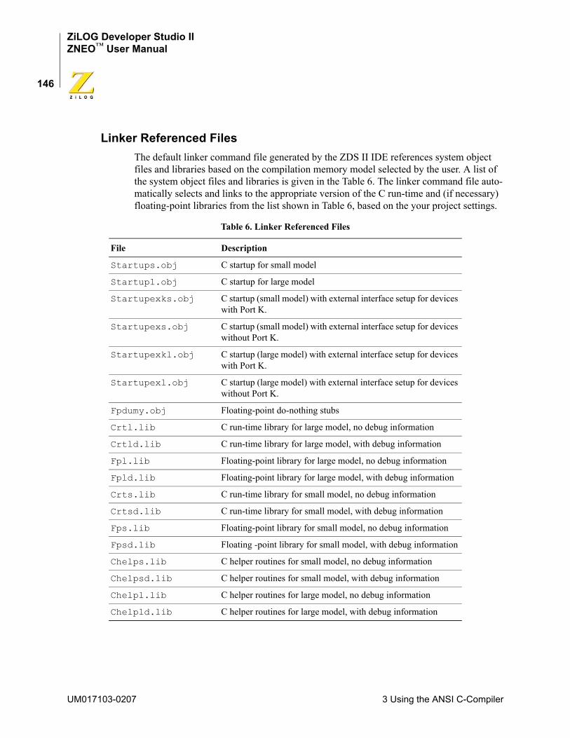
ZiLOG Developer Studio IIZNEO™ User Manual
146
Linker Referenced FilesThe default linker command file generated by the ZDS II IDE references system object files and libraries based on the compilation memory model selected by the user. A list of the system object files and libraries is given in the Table 6. The linker command file auto-matically selects and links to the appropriate version of the C run-time and (if necessary) floating-point libraries from the list shown in Table 6, based on the your project settings.
Table 6. Linker Referenced Files
File Description
Startups.obj C startup for small model
Startupl.obj C startup for large model
Startupexks.obj C startup (small model) with external interface setup for devices with Port K.
Startupexs.obj C startup (small model) with external interface setup for devices without Port K.
Startupexkl.obj C startup (large model) with external interface setup for devices with Port K.
Startupexl.obj C startup (large model) with external interface setup for devices without Port K.
Fpdumy.obj Floating-point do-nothing stubs
Crtl.lib C run-time library for large model, no debug information
Crtld.lib C run-time library for large model, with debug information
Fpl.lib Floating-point library for large model, no debug information
Fpld.lib Floating-point library for large model, with debug information
Crts.lib C run-time library for small model, no debug information
Crtsd.lib C run-time library for small model, with debug information
Fps.lib Floating-point library for small model, no debug information
Fpsd.lib Floating -point library for small model, with debug information
Chelps.lib C helper routines for small model, no debug information
Chelpsd.lib C helper routines for small model, with debug information
Chelpl.lib C helper routines for large model, no debug information
Chelpld.lib C helper routines for large model, with debug information
UM017103-0207 3 Using the ANSI C-Compiler
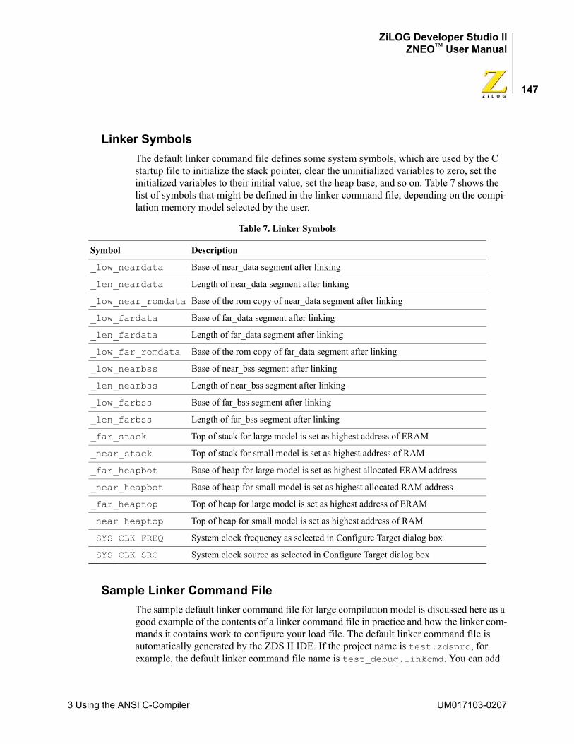
ZiLOG Developer Studio IIZNEO™ User Manual
147
Linker SymbolsThe default linker command file defines some system symbols, which are used by the C startup file to initialize the stack pointer, clear the uninitialized variables to zero, set the initialized variables to their initial value, set the heap base, and so on. Table 7 shows the list of symbols that might be defined in the linker command file, depending on the compi-lation memory model selected by the user.
Sample Linker Command FileThe sample default linker command file for large compilation model is discussed here as a good example of the contents of a linker command file in practice and how the linker com-mands it contains work to configure your load file. The default linker command file is automatically generated by the ZDS II IDE. If the project name is test.zdspro, for example, the default linker command file name is test_debug.linkcmd. You can add
Table 7. Linker Symbols
Symbol Description
_low_neardata Base of near_data segment after linking
_len_neardata Length of near_data segment after linking
_low_near_romdata Base of the rom copy of near_data segment after linking
_low_fardata Base of far_data segment after linking
_len_fardata Length of far_data segment after linking
_low_far_romdata Base of the rom copy of far_data segment after linking
_low_nearbss Base of near_bss segment after linking
_len_nearbss Length of near_bss segment after linking
_low_farbss Base of far_bss segment after linking
_len_farbss Length of far_bss segment after linking
_far_stack Top of stack for large model is set as highest address of ERAM
_near_stack Top of stack for small model is set as highest address of RAM
_far_heapbot Base of heap for large model is set as highest allocated ERAM address
_near_heapbot Base of heap for small model is set as highest allocated RAM address
_far_heaptop Top of heap for large model is set as highest address of ERAM
_near_heaptop Top of heap for small model is set as highest address of RAM
_SYS_CLK_FREQ System clock frequency as selected in Configure Target dialog box
_SYS_CLK_SRC System clock source as selected in Configure Target dialog box
3 Using the ANSI C-Compiler UM017103-0207
ZiLOG Developer Studio IIZNEO™ User Manual
148
additional directives to the linking process by specifying them in the Additional Linker Directives dialog box (see “Additional Directives” on page 68). Alternatively, you can define your own linker command file by selecting the Use Existing button (see “Use Exist-ing” on page 69).
The most important of the linker commands and options in the default linker command file are now discussed individually, in the order in which they are typically found in the linker command file:-FORMAT=OMF695, INTEL32-map -maxhexlen=64 -quiet -warnoverlap -NOxref -unresolved=fatal -sort NAME=ascending -warn –debug -NOigcase
In this command, the linker output file format is selected to be OMF695, which is based on the IEEE 695 object file format, and INTEL32, which is the Intel Hex 32 format. This setting is generated from options selected in Output page (see page 78). The –quiet, -debug, and –noigcase options are generated from the settings on the General page (see page 54). The other options shown here are all generated from the settings selected in the Warnings and Output pages (see page 77 and page 78).RANGE ROM $0 : $7fffRANGE RAM $ffb000 : $ffbfffRANGE EROM $8000 : $1ffffRANGE ERAM $800000 : $81ffff
The ranges for the four address spaces are defined here. These ranges are taken from the settings in Address Spaces page (see page 74).CHANGE NEAR_TEXT=NEAR_DATACHANGE FAR_TEXT=FAR_DATA
The NEAR_TEXT and FAR_TEXT segments are renamed to NEAR_DATA and FAR_DATA segments, respectively, by the above command. This allows the linker to merge them with the material that has already been placed into the NEAR_DATA and FAR_DATA segments. The NEAR_TEXT and FAR_TEXT segments contain constant strings in RAM and ERAM, respectively. This reduces the number of initialized segments from four to two, and the C startup then only needs to initialize two segments.ORDER FAR_BSS, FAR_DATAORDER NEAR_BSS,NEAR_DATA
These ORDER commands specify the link order of these segments. The FAR_BSS seg-ment is placed at lower addresses with the FAR_DATA segment immediately following it in the ERAM space. Similarly, NEAR_DATA follows after NEAR_BSS in RAM space.COPY NEAR_DATA EROMCOPY FAR_DATA EROM
This COPY command is a linker directive to make the linker place a copy of the initialized data segments NEAR_DATA and FAR_DATA into the EROM address space. At run time, the C startup module then copies the initialized data back from the EROM address space to the RAM (NEAR_DATA segment) and ERAM (FAR_DATA segment) address spaces.
UM017103-0207 3 Using the ANSI C-Compiler
ZiLOG Developer Studio IIZNEO™ User Manual
149
This is the standard method to ensure that variables get their required initialization from a nonvolatile stored copy in a typical embedded application where there is no offline mem-ory such as disk storage from which initialized variables can be loaded.define _low_near_romdata = copy base of NEAR_DATAdefine _low_neardata = base of NEAR_DATAdefine _len_neardata = length of NEAR_DATAdefine _low_far_romdata = copy base of FAR_DATAdefine _low_fardata = base of FAR_DATAdefine _len_fardata = length of FAR_DATAdefine _low_nearbss = base of NEAR_BSSdefine _len_nearbss = length of NEAR_BSSdefine _low_farbss = base of FAR_BSSdefine _len_farbss = length of FAR_BSSdefine _far_heapbot = top of ERAMdefine _far_heaptop = highaddr of ERAMdefine _far_stack = highaddr of ERAMdefine _near_heapbot = top of RAMdefine _near_heaptop = highaddr of RAMdefine _near_stack = highaddr of RAM
These are the linker symbol definitions described in Table 7. They allow the compiler to know the bounds of the different memory areas that must be initialized in different ways by the C startup module."c:\sample\test"= \
C:\PROGRA~1\ZiLOG\ZD3E4C~1.0\lib\startupL.obj, \.\foo.obj, \C:\PROGRA~1\ZiLOG\ZD3E4C~1.0\lib\chelpLD.lib, \C:\PROGRA~1\ZiLOG\ZD3E4C~1.0\lib\crtLD.lib, \C:\PROGRA~1\ZiLOG\ZD3E4C~1.0\lib\fpLD.lib
This final command shows that, in this example, the linker output file is named test.lod. The source object file (foo.obj) is to be linked with the other modules that are required to make a complete executable load file. In this case, those other modules are the C startup modules for the large model (startupl.obj), the C helper library for the large model with debug (chelpld.lib), the C run-time library for the large model with debug (crtld.lib), and the floating-point library for that same configuration (fpld.lib).
An important point to understand in using the linker is that if you use the ZiLOG default version of the C run-time library, the linker will link in only those functions that are actu-ally called in your program. This is because the ZiLOG default library is organized with only one function (or in a few cases, a few closely related functions) in each module. Although the C run-time library contains a very large number of functions from the C standard library, if your application only calls two of those functions, then only those two are linked into your application (plus any functions that are called by those two functions in turn). This means it is safe for you to simply link in a large library, like chelpLD.lib, crtLD.lib, and fpLD.lib in this example. You do not have to worry about any
3 Using the ANSI C-Compiler UM017103-0207
ZiLOG Developer Studio IIZNEO™ User Manual
150
unnecessary code being linked in and do not have to do the extra work of painstakingly finding the unresolved symbols for yourself and linking only to those specific functions. See “Use Default Libraries” on page 73 for a further discussion of this area.
ANSI STANDARD COMPLIANCEThe ZiLOG ZNEO C-Compiler is a freestanding ANSI C compiler, complying with the 1989 ISO standard, which is also known as ANSI Standard X3.159-1989 with some devi-ations, which are described in “Deviations from ANSI C” on page 150.
Freestanding ImplementationA “freestanding” implementation of the C language is a concept defined in the ANSI stan-dard itself, to accommodate the needs of embedded applications that cannot be expected to provide all the services of the typical desktop execution environment (which is called a hosted environment in the terms of the standard). In particular, it is presumed that there are no file system and no operating system. The use of the standard term “freestanding imple-mentation” means that the compiler must contain, at least, a specific subset of the full ANSI C features. This subset consists of those basic language features appropriate to embedded applications. Specifically the list of required header files and associated library functions is minimal, namely <float.h>, <limits.h>, <stdarg.h>, and <stddef.h>. A freestanding implementation is allowed to additionally support all or parts of other standard header files but is not required to. The ZNEO C-Compiler, for example, supports a number of additional headers from the standard library, as specified in “Library Files Not Required for Freestanding Implementation” on page 151.
A “conforming implementation” (that is, compiler) is allowed to provide extensions, as long as they do not alter the behavior of any program that uses only the standard features of the language. The ZiLOG ZNEO C-Compiler uses this concept to provide language extensions that are useful for developing embedded applications and for making efficient use of the resources of the ZNEO CPU. These extensions are described in “Language Extensions” on page 114.
Deviations from ANSI CThe differences between the ZiLOG ZNEO C-Compiler and the freestanding implementa-tion of ANSI C Standard consist of both extensions to the ANSI standard and deviations from the behavior described by the standard. The extensions to the ANSI standard are explained in “Language Extensions” on page 114.
There are a small number of areas in which the ZNEO C-Compiler does not behave as specified by the Standard. These areas are described in the following sections.
UM017103-0207 3 Using the ANSI C-Compiler
ZiLOG Developer Studio IIZNEO™ User Manual
151
Prototype of MainAs per ANSI C, in a freestanding environment, the name and type of the function called at program startup are implementation defined. Also, the effect of program termination is implementation defined.
For compatibility with hosted applications, the ZNEO C-Compiler uses main() as the function called at program startup. Because the ZNEO compiler provides a freestanding execution environment, there are a few differences in the syntax for main(). The most important of these is that, in a typical small embedded application, main() never executes a return as there is no operating system for a value to be returned to and is also not intended to terminate. If main() does terminate, and the standard ZiLOG ZNEO C startup module is in use, control simply goes to the statement:_exit:
JP _exit
For this reason, in the ZNEO C-Compiler, main() needs to be of type void; any returned value is ignored. Also, main() is not passed any arguments. In short, the following is the prototype for main():void main (void);
Unlike the hosted environment in which the closest allowed form for main is as follows:int main (void);
Double Treated as FloatThe ZNEO C-Compiler does not support a double-precision floating-point type. The type double is accepted, but is treated as if it were float.
Library Files Not Required for Freestanding ImplementationAs noted in “Freestanding Implementation” on page 150, only four of the standard library header files are required by the standard to be supported in a freestanding compiler such as the ZNEO C-Compiler. However, the compiler does support many of the other standard library headers as well. The supported headers are listed here. The support offered in the ZiLOG libraries is fully compliant with the Standard except as noted here:
• <assert.h>
• <ctype.h>
• <errno.h>
• <math.h>
The ZiLOG implementation of this library is not fully ANSI compliant in the general limitations of the handling of floating-point numbers: namely, ZiLOG does not fully support floating-point NANs, INFINITYs, and related special values. These special values are part of the full ANSI/IEEE 754-1985 floating-point standard that is referenced in the ANSI C Standard.
3 Using the ANSI C-Compiler UM017103-0207
ZiLOG Developer Studio IIZNEO™ User Manual
152
• <stddef.h>
• <stdio.h>
ZiLOG supports only the portions of stdio.h that make sense in the embedded environment. Specifically, ZiLOG defines the ANSI required functions that do not depend on a file system. For example, printf and sprintf are supplied but not fprintf.
• <stdlib.h>
This header is ANSI compliant in the ZiLOG library except that the following functions of limited or no use in an embedded environment are not supplied:
strtoul()_Exit()atexit()
WARNING AND ERROR MESSAGESNOTE: If you see an internal error message, please report it to Technical Support at
http://support.zilog.com. ZiLOG staff will use the information to diagnose or log the problem.
This section covers the following:
• “Preprocessor Warning and Error Messages” on page 152
• “Front-End Warning and Error Messages” on page 155
• “Optimizer Warning and Error Messages” on page 164
• “Code Generator Warning and Error Messages” on page 166
Preprocessor Warning and Error Messages000 Illegal constant expression in directive.
A constant expression made up of constants and macros that evaluate to constants can be the only operands of an expression used in a preprocessor directive.
001 Concatenation at end-of-file. Ignored.
An attempt was made to concatenate lines with a backslash when the line is the last line of the file.
002 Illegal token.
An unrecognizable token or non-ASCII character was encountered.
003 Illegal redefinition of macro <name>.
An attempt was made to redefine a macro, and the tokens in the macro definition do not match those of the previous definition.
UM017103-0207 3 Using the ANSI C-Compiler
ZiLOG Developer Studio IIZNEO™ User Manual
153
004 Incorrect number of arguments for macro <name>.
An attempt was made to call a macro, but too few or too many arguments were given.
005 Unbalanced parentheses in macro call.
An attempt was made to call a macro with a parenthesis embedded in the argument list that did not match up.
006 Cannot redefine <name> keyword.
An attempt was made to redefine a keyword as a macro.
007 Illegal directive.
The syntax of a preprocessor directive is incorrect.
008 Illegal "#if" directive syntax.
The syntax of a #if preprocessor directive is incorrect.
009 Bad preprocessor file. Aborted.
An unrecognizable source file was given to the compiler.
010 Illegal macro call syntax.
An attempt was made to call a macro that does not conform to the syntax rules of the language.
011 Integer constant too large.
An integer constant that has a binary value too large to be stored in 32 bits was encountered.
012 Identifier <name> is undefined
The syntax of the identifier is incorrect.
013 Illegal #include argument.
The argument to a #include directive must be of the form "pathname" or <filename>.
014 Macro "<name>" requires arguments.
An attempt was made to call a macro defined to have arguments and was given none.
015 Illegal "#define" directive syntax.
The syntax of the #define directive is incorrect.
016 Unterminated comment in preprocessor directive.
Within a comment, an end of line was encountered.
017 Unterminated quoted string.
Within a quoted string, an end of line was encountered.
3 Using the ANSI C-Compiler UM017103-0207
ZiLOG Developer Studio IIZNEO™ User Manual
154
018 Escape sequence ASCII code too large to fit in char.
The binary value of an escape sequence requires more than 8 bits of storage.
019 Character not within radix.
An integer constant was encountered with a character greater than the radix of the constant.
020 More than four characters in string constant.
A string constant was encountered having more than four ASCII characters.
021 End of file encountered before end of macro call.
The end of file is reached before right parenthesis of macro call.
022 Macro expansion caused line to be too long.
The line needs to be shortened.
023 "##" cannot be first or last token in replacement string.
The macro definition cannot have “##” operator in the beginning or end.
024 "#" must be followed by an argument name.
In a macro definition, “#” operator must be followed by an argument.
025 Illegal "#line" directive syntax.
In #line <linenum> directive, <linenum> must be an integer after macro expansion.
026 Cannot undefine macro "name".
The syntax of the macro is incorrect.
027 End-of-file found before "#endif" directive.
#if directive was not terminated with a corresponding #endif directive.
028 "#else" not within #if and #endif directives.
#else directive was encountered before a corresponding #if directive.
029 Illegal constant expression.
The constant expression in preprocessing directive has invalid type or syntax.
030 Illegal macro name <name>.
The macro name does not have a valid identifier syntax.
031 Extra "#endif" found.
#endif directive without a corresponding #if directive was found.
032 Division by zero encountered.
Divide by zero in constant expression found.
UM017103-0207 3 Using the ANSI C-Compiler
ZiLOG Developer Studio IIZNEO™ User Manual
155
033 Floating point constant over/underflow.
In the process of evaluating a floating-point expression, the value became too large to be stored.
034 Concatenated string too long.
Shorten the concatenated string.
035 Identifier longer than 32 characters.
Identifiers must be 32 characters or shorter.
036 Unsupported CPU "name" in pragma.
An unknown CPU encountered.
037 Unsupported or poorly formed pragma.
An unknown #pragma directive encountered.
038 (User-supplied text)
A user-created #error directive has been encountered. The user-supplied text from the directive is printed with the error message.
Front-End Warning and Error Messages100 Syntax error.
A syntactically incorrect statement, declaration, or expression was encountered.
101 Function "<name>" already declared.
An attempt was made to define two functions with the same name.
102 Constant integer expression expected.
A non-integral expression was encountered where only an integral expression can be.
103 Constant expression overflow.
In the process of evaluating a constant expression, value became too large to be stored in 32 bits.
104 Function return type mismatch for "<name>".
A function prototype or function declaration was encountered that has a different result from a previous declaration.
105 Argument type mismatch for argument <name>.
The type of an actual parameter does not match the type of the formal parameter of the function called.
3 Using the ANSI C-Compiler UM017103-0207
ZiLOG Developer Studio IIZNEO™ User Manual
156
106 Cannot take address of un-subscripted array.
An attempt was made to take the address of an array with no index. The address of the array is already implicitly calculated.
107 Function call argument cannot be void type.
An attempt was made to pass an argument to a function that has type void.
108 Identifier "<name>" is not a variable or enumeration constant name.
In a declaration, a reference to an identifier was made that was not a variable name or an enumeration constant name.
109 Cannot return a value from a function returning "void".
An attempt was made to use a function defined as returning void in an expression.
110 Expression must be arithmetic, structure, union or pointer type.
The type of an operand to a conditional expression was not arithmetic, structure, union or pointer type.
111 Integer constant too large
Reduce the size of the integer constant.
112 Expression not compatible with function return type.
An attempt was made to return a value from function that cannot be promoted to the type defined by the function declaration.
113 Function cannot return value of type array or function.
An attempt was made to return a value of type array or function.
114 Structure or union member may not be of function type.
An attempt was made to define a member of structure or union that has type function.
115 Cannot declare a typedef within a structure or union.
An attempt was made to declare a typedef within a structure or union.
116 Illegal bit field declaration.
An attempt was made to declare a structure or union member that is a bit field and is syntactically incorrect.
117 Unterminated quoted string
Within a quoted string, an end of line was encountered.
118 Escape sequence ASCII code too large to fit in char
The binary value of an escape sequence requires more than 8 bits of storage.
UM017103-0207 3 Using the ANSI C-Compiler
ZiLOG Developer Studio IIZNEO™ User Manual
157
119 Character not within radix
An integer constant was encountered with a character greater than the radix of the constant.
120 More than one character in string constant
A string constant was encountered having more than one ASCII character.
121 Illegal declaration specifier.
An attempt was made to declare an object with an illegal declaration specifier.
122 Only "const" and "volatile" may be specified with a struct, union, enum, or typedef.
An attempt was made to declare a struct, union, enum, or typedef with a declaration specifier other than const and volatile.
123 Cannot specify both long and short in declaration specifier.
An attempt was made to specify both long and short in the declaration of an object.
124 Only type qualifiers may be specified within pointer declarations.
An attempt was made to declare a pointer with a declaration specifier other than const and volatile.
125 Identifier "<name>" already declared within current scope.
An attempt was made to declare two objects of the same name in the same scope.
126 Identifier "<name>" not in function argument list, ignored.
An attempt was made to declare an argument that is not in the list of arguments when using the old style argument declaration syntax.
127 Name of formal parameter not given.
The type of a formal parameter was given in the new style of argument declarations without giving an identifier name.
128 Identifier "<name>" not defined within current scope.
An identifier was encountered that is not defined within the current scope.
129 Cannot have more than one default per switch statement.
More than one default statements were found in a single switch statement.
130 Label "<name>" is already declared.
An attempt was made to define two labels of the same name in the same scope.
131 Label "<name> not declared.
A goto statement was encountered with an undefined label.
3 Using the ANSI C-Compiler UM017103-0207
ZiLOG Developer Studio IIZNEO™ User Manual
158
132 "continue" statement not within loop body.
A continue statement was found outside a body of any loop.
133 "break" statement not within switch body or loop body.
A break statement was found outside the body of any loop.
134 "case" statement must be within switch body.
A case statement was found outside the body of any switch statement.
135 "default" statement must be within switch body.
A default statement was found outside the body of any switch statement.
136 Case value <name> already declared.
An attempt was made to declare two cases with the same value.
137 Expression is not a pointer.
An attempt was made to dereference a value of an expression whose type is not a pointer.
138 Expression is not a function locator.
An attempt was made to use an expression as the address of a function call that does not have a type pointer to function.
139 Expression to left of "." or "->" is not a structure or union.
An attempt was made to use an expression as a structure or union, or a pointer to a structure or union, whose type was neither a structure or union, or a pointer to a structure or union.
140 Identifier "<name>" is not a member of <name> structure.
An attempt was made to reference a member of a structure that does not belong to the structure.
141 Object cannot be subscripted.
An attempt was made to use an expression as the address of an array or a pointer that was not an array or pointer.
142 Array subscript must be of integral type.
An attempt was made to subscript an array with a non integral expression.
143 Cannot dereference a pointer to "void".
An attempt was made to dereference a pointer to void.
144 Cannot compare a pointer to a non-pointer.
An attempt was made to compare a pointer to a non-pointer.
UM017103-0207 3 Using the ANSI C-Compiler
ZiLOG Developer Studio IIZNEO™ User Manual
159
145 Pointers to different types may not be compared.
An attempt was made to compare pointers to different types.
146 Pointers may not be added.
It is not legal to add two pointers.
147 A pointer and a non-integral may not be subtracted.
It is not legal to subtract a non-integral expression from a pointer.
148 Pointers to different types may not be subtracted.
It is not legal to subtract two pointers of different types.
149 Unexpected end of file encountered.
In the process of parsing the input file, end of file was reached during the evaluation of an expression, statement, or declaration.
150 Unrecoverable parse error detected.
The compiler became confused beyond the point of recovery.
151 Operand must be a modifiable lvalue.
An attempt was made to assign a value to an expression that was not modifiable.
152 Operands are not assignment compatible.
An attempt was made to assign a value whose type cannot be promoted to the type of the destination.
153 "<name>" must be arithmetic type.
An expression was encountered whose type was not arithmetic where only arithmetic types are allowed.
154 "<name>" must be integral type.
An expression was encountered whose type was not integral where only integral types are allowed.
155 "<name>" must be arithmetic or pointer type.
An expression was encountered whose type was not pointer or arithmetic where only pointer and arithmetic types are allowed.
156 Expression must be an lvalue.
An expression was encountered that is not an lvalue where only an lvalue is allowed.
157 Cannot assign to an object of constant type.
An attempt was made to assign a value to an object defined as having constant type.
3 Using the ANSI C-Compiler UM017103-0207
ZiLOG Developer Studio IIZNEO™ User Manual
160
158 Cannot subtract a pointer from an arithmetic expression.
An attempt was made to subtract a pointer from an arithmetic expression.
159 An array is not a legal lvalue.
Cannot assign an array to an array.
160 Cannot take address of a bit field.
An attempt was made to take the address of a bit field.
161 Cannot take address of variable with "register" class.
An attempt was made to take the address of a variable with "register" class.
162 Conditional expression operands are not compatible.
One operand of a conditional expression cannot be promoted to the type of the other operand.
163 Casting a non-pointer to a pointer.
An attempt was made to promote a non-pointer to a pointer.
164 Type name of cast must be scalar type.
An attempt was made to cast an expression to a non-scalar type.
165 Operand to cast must be scalar type.
An attempt was made to cast an expression whose type was not scalar.
166 Expression is not a structure or union.
An expression was encountered whose type was not structure or union where only a structure or union is allowed.
167 Expression is not a pointer to a structure or union.
An attempt was made to dereference a pointer with the arrow operator, and the expression’s type was not pointer to a structure or union.
168 Cannot take size of void, function, or bit field types.
An attempt was made to take the size of an expression whose type is void, function, or bit field.
169 Actual parameter has no corresponding formal parameter.
An attempt was made to call a function whose formal parameter list has fewer elements than the number of arguments in the call.
170 Formal parameter has no corresponding actual parameter.
An attempt was made to call a function whose formal parameter list has more elements than the number of arguments in the call.
UM017103-0207 3 Using the ANSI C-Compiler
ZiLOG Developer Studio IIZNEO™ User Manual
161
171 Argument type is not compatible with formal parameter.
An attempt was made to call a function with an argument whose type is not compatible with the type of the corresponding formal parameter.
172 Identifier "<name>" is not a structure or union tag.
An attempt was made to use the dot operator on an expression whose type was not structure or union.
173 Identifier "<name>" is not a structure tag.
The tag of a declaration of a structure object does not have type structure.
174 Identifier "<name>" is not a union tag.
The tag of a declaration of a union object does not have type union.
175 Structure or union tag "<name>" is not defined.
The tag of a declaration of a structure or union object is not defined.
176 Only one storage class may be given in a declaration.
An attempt was made to give more than one storage class in a declaration.
177 Type specifier cannot have both "unsigned" and "signed".
An attempt was made to give both unsigned and signed type specifiers in a declaration.
178 "unsigned" and "signed" may be used in conjunction only with "int", "long" or "char".
An attempt was made to use signed or unsigned in conjunction with a type specifier other than int, long, or char.
179 "long" may be used in conjunction only with "int" or "double".
An attempt was made to use long in conjunction with a type specifier other than int or double.
180 Illegal bit field length.
The length of a bit field was outside of the range 0-32.
181 Too many initializers for object.
An attempt was made to initialize an object with more elements than the object contains.
182 Static objects can be initialized with constant expressions only.
An attempt was made to initialize a static object with a non-constant expression.
183 Array "<name>" has too many initializers.
An attempt was made to initialize an array with more elements than the array contains.
3 Using the ANSI C-Compiler UM017103-0207
ZiLOG Developer Studio IIZNEO™ User Manual
162
184 Structure "<name>" has too many initializers.
An attempt was made to initialize a structure with more elements than the structure has members.
185 Dimension size may not be omitted.
An attempt was made to omit the dimension of an array which is not the rightmost dimension.
186 First dimension of "<name>" may not be omitted.
An attempt was made to omit the first dimension of an array which is not external and is not initialized.
187 Dimension size must be greater than zero.
An attempt was made to declare an array with a dimension size of zero.
188 Only "register" storage class is allowed for formal parameter.
An attempt was made to declare a formal parameter with storage class other than register.
189 Cannot take size of array with missing dimension size.
An attempt was made to take the size of an array with an omitted dimension.
190 Identifier "<name>" already declared with different type or linkage.
An attempt was made to declare a tentative declaration with a different type than a declaration of the same name; or, an attempt was made to declare an object with a different type from a previous tentative declaration.
191 Cannot perform pointer arithmetic on pointer to void.
An attempt was made to perform pointer arithmetic on pointer to void.
192 Cannot initialize object with "extern" storage class.
An attempt was made to initialize variable with extern storage class.
193 Missing "<name>" detected.
An attempt was made to use a variable without any previous definition or declaration.
194 Recursive structure declaration.
A structure member can not be of same type as the structure itself.
195 Initializer is not assignment compatible.
The initializer type does not match with the variable being initialized.
196 Empty parameter list is an obsolescent feature.
Empty parameter lists are not allowed.
UM017103-0207 3 Using the ANSI C-Compiler
ZiLOG Developer Studio IIZNEO™ User Manual
163
197 No function prototype "<name>" in scope.
The function <name> is called without any previous definition or declaration.
198 "old style" formal parameter declarations are obsolescent.
Change the parameter declarations.
201 Only one memory space can be specified
An attempt was made to declare a variable with multiple memory space specifier.
202 Unrecognized/invalid type specifier
An attempt was made to declare a variable with unknown type specifier.
204 Ignoring space specifiers (e.g. near, far, rom) on local, parameter or struct member
An attempt was made to declare a local, parameter, or struct member with a memory space specifier. The space specifier for a local or parameter is decided based on the memory model chosen. The space specifier for a struct member is decided based on the space specifier of the entire struct. Any space specifier on local, parameter, or struct member is ignored.
205 Ignoring const or volatile qualifier
An attempt was made to assign a pointer to a type with const qualifier to a pointer to a type with no const qualifier.
or
An attempt was made to assign a pointer to a type with volatile qualifier to a pointer to a type with no volatile qualifier.
206 Cannot initialize typedef
An attempt was made to initialize a typedef.
207 Aggregate or union objects may be initialized with constant expressions only
An attempt was made to initiaze an array or struct with non constant expression.
208 Operands are not cast compatible
An attempt was made to cast a variable to an uncompatible type, for example, casting a _Far pointer to a _Near pointer.
209 Ignoring space specifier (e.g. near, far) on function
An attempt was made to designate a function as a _Near or a _Far function.
210 Invalid use of placement or alignment option
An attempt was made to use a placement or alignment option on a local or parameter.
212 No previous use of placement or alignment options
3 Using the ANSI C-Compiler UM017103-0207
ZiLOG Developer Studio IIZNEO™ User Manual
164
An attempt was made to use the _At … directive without any previous use of the _At address directive.
213 Function "<name>" must return a value
An attempt was made to return from a non void function without providing a return value.
214 Function return type defaults to int
The return type of the function was not specified so the default return type was assumed. A function that does not return anything should be declared as void.
215 Signed/unsigned mismatch
An attempt was made to assign a pointer to a signed type with a pointer to an unsigned type and vice versa.
Optimizer Warning and Error Messages250 Missing format parameter to (s)printf
This message is generated when a call to printf or sprintf is missing the format parameter and the inline generation of printf calls is requested. For example, a call of the formprintf();
251 Can't preprocess format to (s)printf
This message is generated when the format parameter to printf or sprintf is not a string literal and the inline generation of printf calls is requested. For example, the following code causes this warning:static char msg1 = "x = %4d";char buff[sizeof(msg1)+4];sprintf(buff,msg1,x); // WARNING HERE
This warning is generated because the line of code is processed by the real printf or sprintf function, so that the primary goal of the inline processing, reducing the code size by removing these functions, is not met.
When this message is displayed, you have three options:– Deselect the Generate Printfs Inline check box (see “Generate Printfs Inline” on
page 64) so that all calls to printf and sprintf are handled by the real printf or sprintf functions.
– Recode to pass a string literal. For example, the code in the example can be revised as follows:
define MSG1 "x = %4d"char buff[sizeof(MSG1)+4];sprintf(buff,MSG1,x); // OK
UM017103-0207 3 Using the ANSI C-Compiler
ZiLOG Developer Studio IIZNEO™ User Manual
165
– Keep the Generate Printfs Inline check box selected and ignore the warning. This loses the primary goal of the option but results in the faster execution of the calls to printf or sprintf that can be processed at compile time, a secondary goal of the option.
252 Bad format string passed to (s)printf
This warning occurs when the compiler is unable to parse the string literal format and the inline generation of printf calls is requested. A normal call to printf or sprintf is generated (which might also be unable to parse the format).
253 Too few parameters for (s)printf format
This error is generated when there are fewer parameters to a call to printf or sprintf than the format string calls for and the inline generation of printf calls is requested. For example:printf("x = %4d\n");
254 Too many parameters for (s)printf format
This warning is generated when there are more parameters to a call to printf or sprintf than the format string calls for and the inline generation of printf calls is requested. For example:printf("x = %4d\n", x, y);
The format string is parsed, and the extra arguments are ignored.
255 Missing declaration of (s)printf helper function, variable, or field
This warning is generated when the compiler has not seen the prototypes for the printf or sprintf helper functions it generates calls to. This occurs if the standard include file stdio.h has not been included or if stdio.h from a different release of ZDS II has been included.
256 Can't preprocess calls to vprintf or vsprintf
This message is generated when the code contains calls to vprintf or vsprintf and the inline generation of printf calls is requested. The reason for this warning and the solutions are similar to the ones for message 201: Can’t preprocess format to (s)printf.
257 Not all paths through “<name>” return a value
The function declared with a return type is not returning any value at least on one path in the function.
3 Using the ANSI C-Compiler UM017103-0207
ZiLOG Developer Studio IIZNEO™ User Manual
166
Code Generator Warning and Error Messages303 Case value <number> already defined.
If a case value consists of an expression containing a sizeof, its value is not known until code generation time. Thus, it is possible to have two cases with the same value not caught by the front end. Review the switch statement closely.
309 Interrupt function <name> cannot have arguments.
A function declared as an interrupt function cannot have function arguments.
313 Bitfield Length exceeds x bits.
The compiler only accepts bit-field lengths of 8 bits or less for char bit-fields, 16 bit or less for short bit-fields and 32 bit or less for int and long bit-fields.
UM017103-0207 3 Using the ANSI C-Compiler
ZiLOG Developer Studio IIZNEO™ User Manual
167
4 Using the Macro AssemblerYou use the Macro Assembler to translate ZNEO assembly language files with the .asm extension into relocatable object modules with the .obj extension. After your relocatable object modules are complete, you convert them into an executable program using the linker/locator. The Macro Assembler can be configured using the Assembler page of the Project Settings dialog box (see page 56).
NOTE: The Command Processor allows you to use commands or script files to automate the execution of a significant portion of the IDE’s functionality. For more information about the Command Processor, see the “Using the Command Processor” appendix on page 307.
The following topics are covered in this section:
• “Address Spaces and Segments” on page 167
• “Output Files” on page 170
• “Source Language Structure” on page 172
• “Expressions” on page 175
• “Directives” on page 181
• “Conditional Assembly” on page 197
• “Macros” on page 200
• “Labels” on page 203
• “Source Language Syntax” on page 205
• “Warning and Error Messages” on page 208
NOTE: For more information about ZNEO CPU instructions, see the “Instruction Set Description” section in the ZNEO CPU User Manual (UM0188).
ADDRESS SPACES AND SEGMENTSThe ZNEO architecture divides the entire memory into various memory regions. These memory regions are depicted by address spaces in the assembler. Each address space can have various segments associated with it. A segment is a contiguous set of memory loca-tions within an address space. The segments can be predefined by the assembler or user defined.
4 Using the Macro Assembler UM017103-0207
ZiLOG Developer Studio IIZNEO™ User Manual
168
Allocating Processor MemoryAll memory locations, whether data or code, must be defined within a segment. There are two types of segments:
• Absolute segments
An absolute segment is any segment with a fixed origin. The origin of a segment can be defined with the ORG directive. All data and code in an absolute segment is located at the specified physical memory address.
• Relocatable segments
A relocatable segment is a segment without a specified origin. At link time, linker commands are used to specify where relocatable segments are to be located within their space. Relocatable segments can be assigned to different physical memory locations without re-assembling.
Address SpacesThe assembler provides the address spaces listed in Table 8, which represent the memory regions of the ZNEO microcontroller.
Code and data are allocated to these spaces by using segments attached to the space.
SegmentsSegments are used to represent regions of memory. Only one segment is considered active at any time during the assembly process. A segment must be defined before setting it as the current segment. Every segment is associated with one and only one address space.
Predefined SegmentsFor convenience, the segments listed in Table 9 are predefined by the assembler.
Table 8. ZNEO Address Spaces
Space ID Description
ROM 16-bit addressable read-only memory
RAM 16-bit addressable read/write memory
EROM 32-bit addressable code memory
ERAM 32-bit addressable extended memory
IODATA 16-bit addressable IO data memory
UM017103-0207 4 Using the Macro Assembler
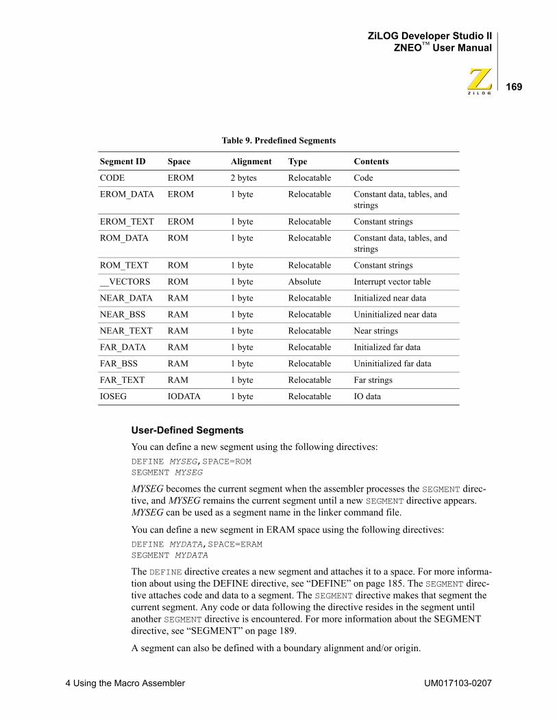
ZiLOG Developer Studio IIZNEO™ User Manual
169
User-Defined SegmentsYou can define a new segment using the following directives:DEFINE MYSEG,SPACE=ROMSEGMENT MYSEG
MYSEG becomes the current segment when the assembler processes the SEGMENT direc-tive, and MYSEG remains the current segment until a new SEGMENT directive appears. MYSEG can be used as a segment name in the linker command file.
You can define a new segment in ERAM space using the following directives:DEFINE MYDATA,SPACE=ERAMSEGMENT MYDATA
The DEFINE directive creates a new segment and attaches it to a space. For more informa-tion about using the DEFINE directive, see “DEFINE” on page 185. The SEGMENT direc-tive attaches code and data to a segment. The SEGMENT directive makes that segment the current segment. Any code or data following the directive resides in the segment until another SEGMENT directive is encountered. For more information about the SEGMENT directive, see “SEGMENT” on page 189.
A segment can also be defined with a boundary alignment and/or origin.
Table 9. Predefined Segments
Segment ID Space Alignment Type Contents
CODE EROM 2 bytes Relocatable Code
EROM_DATA EROM 1 byte Relocatable Constant data, tables, and strings
EROM_TEXT EROM 1 byte Relocatable Constant strings
ROM_DATA ROM 1 byte Relocatable Constant data, tables, and strings
ROM_TEXT ROM 1 byte Relocatable Constant strings
__VECTORS ROM 1 byte Absolute Interrupt vector table
NEAR_DATA RAM 1 byte Relocatable Initialized near data
NEAR_BSS RAM 1 byte Relocatable Uninitialized near data
NEAR_TEXT RAM 1 byte Relocatable Near strings
FAR_DATA RAM 1 byte Relocatable Initialized far data
FAR_BSS RAM 1 byte Relocatable Uninitialized far data
FAR_TEXT RAM 1 byte Relocatable Far strings
IOSEG IODATA 1 byte Relocatable IO data
4 Using the Macro Assembler UM017103-0207
ZiLOG Developer Studio IIZNEO™ User Manual
170
• Alignment: Aligning a segment tells the linker to place all instances of the segment in your program on the specified boundary.
NOTE: Although a module can enter and leave a segment many times, each module still has only one instance of a segment.
• Origin: When a segment is defined with an origin, the segment becomes an absolute segment, and the linker places it at the specified physical address in memory.
Assigning Memory at Link TimeAt link time, the linker groups those segments of code and data that have the same name and places the resulting segment in the address space to which it is attached. However, the linker handles relocatable segments and absolute segments differently:
• Relocatable segments
If a segment is relocatable, the linker decides where in the address space to place the segment.
• Absolute segments
If a segment is absolute, the linker places the segment at the absolute address specified as its origin.
NOTE: At link time, you can redefine segments with the appropriate linker commands.
OUTPUT FILESThe assembler creates the following files and names them the name of the source file but with a different extension:
• <source>.lst contains a readable version of the source and object code generated by the assembler. The assembler creates <source>.lst unless you deselect the Generate Listing File (.lst) check box in the Assembler page of the Project Settings dialog box. See “Generate Assembly Listing Files (.lst)” on page 57.
• <source>.obj is an object file in relocatable OMF695 format. The assembler creates <source>.obj.
Do not use source input files with .lst or .obj extensions. The assembler does not assemble files with these extensions, and therefore the data contained in the files is lost.
Source Listing (.lst) FormatThe listing file name is the same as the source file name with a .lst file extension. Assembly directives allow you to tailor the content and amount of output from the assembler.
Caution:
UM017103-0207 4 Using the Macro Assembler
ZiLOG Developer Studio IIZNEO™ User Manual
171
Each page of the listing file (.lst) contains the following:
• Heading with the assembler version number
• Source input file name
• Date and time of assemblySource lines in the listing file are preceded by the following:
• Include level
• Plus sign (+) if the source line contains a macro
• Line number
• Location of the object code created
• Object codeThe include level starts at level A and works its way down the alphabet to indicate nested includes. The format and content of the listing file can be controlled with directives included in the source file:
• TITLE
• NOLIST
• LIST
• MACLIST ON/OFF
• CONDLIST ON/OFF
NOTE: Error and warning messages follow the source line containing the error(s). A count of the errors and warnings detected is included at the end of the listing output file.
The addresses in the assembly listing are relative. To convert the relative addresses into absolute addresses, select the Show Absolute Addresses in Assembly Listings check box on the Output page of the Project Settings dialog box. This option uses the information in the .src file (generated by the compiler when the Generate Assembly Source Code check box is selected [see “Project Settings—Listing Files Page” on page 59]) and the .map file to change all of the relative addresses in the assembly listing into absolute addresses.
Object Code (.obj) FileThe object code output file name is the same as the source file name with an .obj exten-sion. This file contains the relocatable object code in OMF695 format and is ready to be processed by the linker and librarian.
4 Using the Macro Assembler UM017103-0207
ZiLOG Developer Studio IIZNEO™ User Manual
172
SOURCE LANGUAGE STRUCTUREThis section describes the form of an assembly source file.
General StructureA line in an assembly source file is either a source line or a comment line. The assembler ignores blank lines. Each line of input consists of ASCII characters terminated by a car-riage return. An input line cannot exceed 512 characters.
A backslash (\) at the end of a line is a line continuation. The following line is concate-nated onto the end of the line with the backslash, as exemplified in the C programming language. If you place a space or any other character after the backslash, the following line is not treated as a continuation.
Source LineA source line is composed of an optional label followed by an instruction or a directive. It is possible for a source line to contain only a label field.
Comment LineA semicolon (;) terminates the scanning action of the assembler. Any text following the semicolon is treated as a comment. A semicolon that appears as the first character causes the entire line to be treated as comment.
Label FieldA label must meet at least one of the following conditions:
• It must be followed by a colon.
• It must start at the beginning of the line, with no preceding white space (start in column 1). When an instruction is in the first column, it is treated as a instruction and not a label.
The first character of a label can be a letter, an underscore _ , a dollar sign ($), a question mark (?), a period (.), or pound sign (#). Following characters can include letters, digits, underscores, dollar signs ($), question marks (?), periods (.), or pound signs (#). The label can be followed by a colon (:) that completes the label definition. A label can only be defined once. The maximum label length is 129 characters. See “Labels” on page 203 for more information.
Labels that can be interpreted as hexadecimal numbers are not allowed. For example,ADH:ABEFH:
cannot be used as labels.
See “Labels” on page 203 and “Hexadecimal Numbers” on page 177 for more informa-tion.
UM017103-0207 4 Using the Macro Assembler
ZiLOG Developer Studio IIZNEO™ User Manual
173
InstructionAn instruction contains one valid assembler instruction that consists of a mnemonic and its arguments. When an instruction is in the first column, it is treated as a instruction and not a label. Use commas to separate the operands. Use a semicolon or carriage return to termi-nate the instruction. For more information about ZNEO CPU instructions, see the “Instruction Set Description” section in the ZNEO CPU User Manual (UM0188).
DirectiveA directive tells the assembler to perform a specified task. Use a semicolon or carriage return to terminate the directive. Use spaces or tabs to separate the directive from its oper-ands. See “Directives” on page 181 for more information.
Case SensitivityIn the default mode, the assembler treats all symbols as case sensitive. Select the Ignore Case of Symbols check box of the General page in the Project Settings dialog box to have the assembler ignore the case of user-defined identifiers (see “Ignore Case of Symbols” on page 55). Assembler reserved words are not case sensitive.
Assembler Rules
Reserved WordsThe following list contains reserved words that the assembler uses. You cannot use these words as symbol names or variable names. Also, reserved words are not case sensitive.
.ALIGN .ASCII .ASCIZ .ASECT
.ASG .BES .BLOCK .BSS
.BYTE .chip .COPY .cpu
.DATA .DEF .define .double
.DW24 .ELIF .ELSE .ELSEIF
.EMSG .ENDIF .ENDM .ENDMAC
.ENDMACRO .ENDSTRUCT .EQU .EVAL
.EVEN .EXTERN .FCALL .file
.float .FRAME .GLOBAL .IF
.IFNTRUE .INCLUDE .INT .LIST
.LONG .MACEND .MACRO .MAXBRANCH
.MLIST .MMSG .MNOLIST .NEWBLOCK
.NOLIST .ORG .PAGE .PUBLIC
.REF .SBLOCK .SECT .SET
.SHORT_STACK_FRAME .SPACE .STRING .STRUCT
4 Using the Macro Assembler UM017103-0207
ZiLOG Developer Studio IIZNEO™ User Manual
174
.TAG .TEXT .trio .USECT
.VAR .VECTOR .wmsg .WORD
.word24 ALIGN ASCII ASCIZ
ASECT B BFRACT BLKB
BLKL BLKP BLKW BYTE
C CHIP COMMENT COND
CONDLIST CPU DB DBYTE
DD DEFB DEFINE DF
DL DS DW DW24
ELIF ELSE ELSEIF END
ENDC ENDIF ENDM ENDMAC
ENDMODULE ENDS EQ EQU
EQUAL ERROR EXIT EXTERN
EXTERNAL FCB FILE FP
FRACT GE GLOBAL GLOBALS
GREGISTER GT IF IFDEF
IFDIFF IFE IFEQ IFFALSE
IFMA IFN IFNDEF IFNDIFF
IFNFALSE IFNMA IFNSAME IFNTRUE
IFNZ IFSAME IFTRUE IFZ
INCLUDE LE LEADZERO LFRACT
LIST LONG LOW LOW16
LT MACCNTR MACDELIM MACEND
MACEXIT MACFIRST MACLIST MACNOTE
MAXBRANCH MESSAGE MI NB
NC NE NEWPAGE NOCONDLIST
NOLIST NOMACLIST NOSPAN NOV
NZ OFF ON ORG
ORIGIN OV PAGE PL
POPSEG PRINT PT public
PUSHSEG PW R0 R10
R11 R12 R13 R14
R15 R2 R3 R4
R5 R6 R7 R8
R9 RR0 RR1 RR10
RR11 RR12 RR13 RR14
UM017103-0207 4 Using the Macro Assembler
ZiLOG Developer Studio IIZNEO™ User Manual
175
NOTE: Additionally, do not use the instruction mnemonics or assembler directives as symbol or variable names.
Assembler Numeric RepresentationNumbers are represented internally as signed 32-bit integers. The assembler detects an expression operand that is out of range for the intended field and generates appropriate error messages.
Character StringsCharacter strings consist of printable ASCII characters enclosed by double (") or single (') quotes. A double quote used within a string delimited by double quotes and a single quote used within a string delimited by single quotes must be preceded by a back slash (\). A single quoted string consisting of a single character is treated as a character constant. The assembler does not insert null character (0's) at the end of a text string automatically unless a 0 is inserted, and a character string cannot be used as an operand. For example:DB "STRING" ; a string DB 'STRING',0 ; C printable string DB "STRING\"S" ; embedded quote DB 'a','b','c' ; character constants
EXPRESSIONSIn most cases, where a single integer value can be used as an operand, an expression can also be used. The assembler evaluates expressions in 32-bit signed arithmetic. Logical expressions are bitwise operators.
The assembler detects division-by-zero errors and reports an error message. The following sections describe the syntax of writing an expression.
RR15 RR2 RR3 RR4
RR5 RR6 RR7 RR8
RR9 SCOPE SECTION SEGMENT
SET SP STRING SUBTITLE
TITLE UBFRACT UFRACT UGE
UGT ULE ULFRACT ULT
VAR VECTOR WARNING word
XDEF XREF Z
4 Using the Macro Assembler UM017103-0207
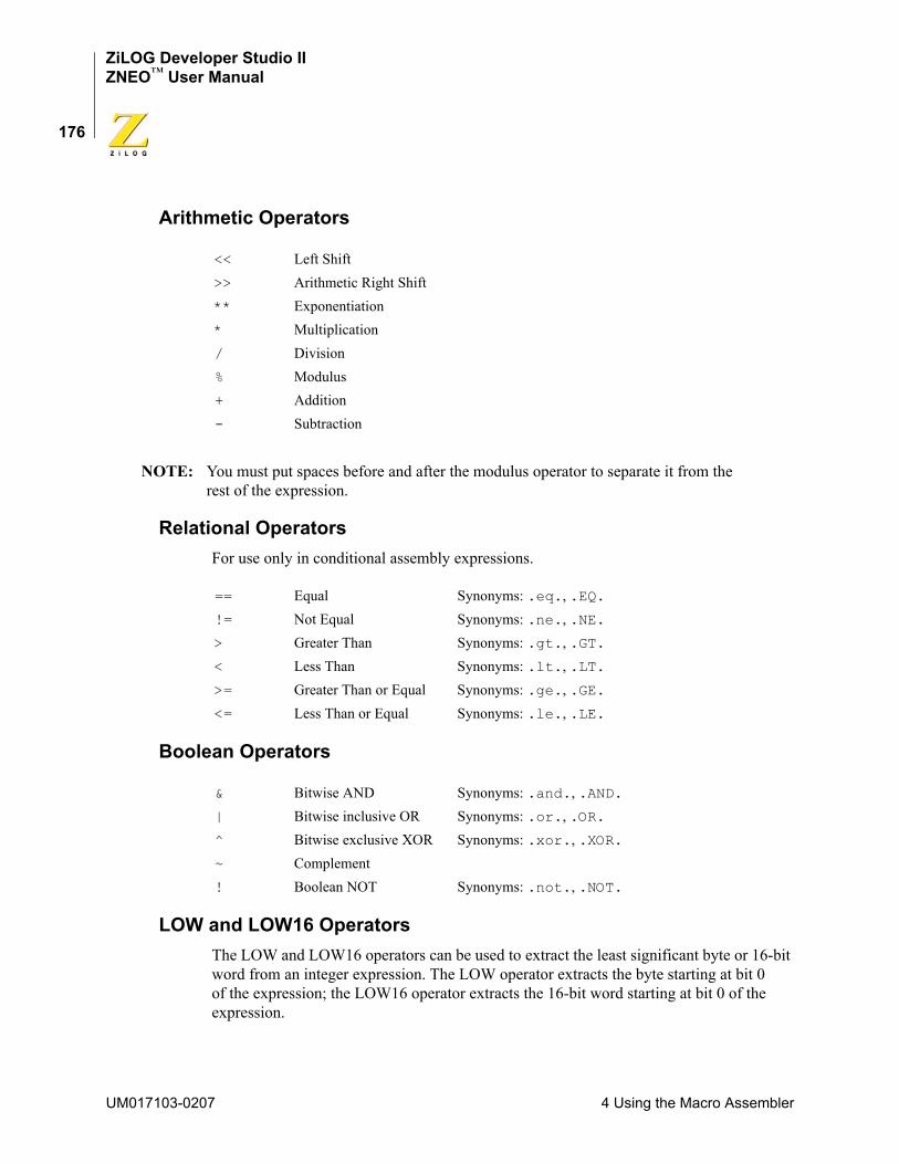
ZiLOG Developer Studio IIZNEO™ User Manual
176
Arithmetic Operators
NOTE: You must put spaces before and after the modulus operator to separate it from the rest of the expression.
Relational OperatorsFor use only in conditional assembly expressions.
Boolean Operators
LOW and LOW16 OperatorsThe LOW and LOW16 operators can be used to extract the least significant byte or 16-bit word from an integer expression. The LOW operator extracts the byte starting at bit 0 of the expression; the LOW16 operator extracts the 16-bit word starting at bit 0 of the expression.
<< Left Shift>> Arithmetic Right Shift** Exponentiation* Multiplication/ Division% Modulus+ Addition- Subtraction
== Equal Synonyms: .eq., .EQ.!= Not Equal Synonyms: .ne., .NE.> Greater Than Synonyms: .gt., .GT.< Less Than Synonyms: .lt., .LT.>= Greater Than or Equal Synonyms: .ge., .GE.<= Less Than or Equal Synonyms: .le., .LE.
& Bitwise AND Synonyms: .and., .AND.| Bitwise inclusive OR Synonyms: .or., .OR.^ Bitwise exclusive XOR Synonyms: .xor., .XOR.~ Complement! Boolean NOT Synonyms: .not., .NOT.
UM017103-0207 4 Using the Macro Assembler
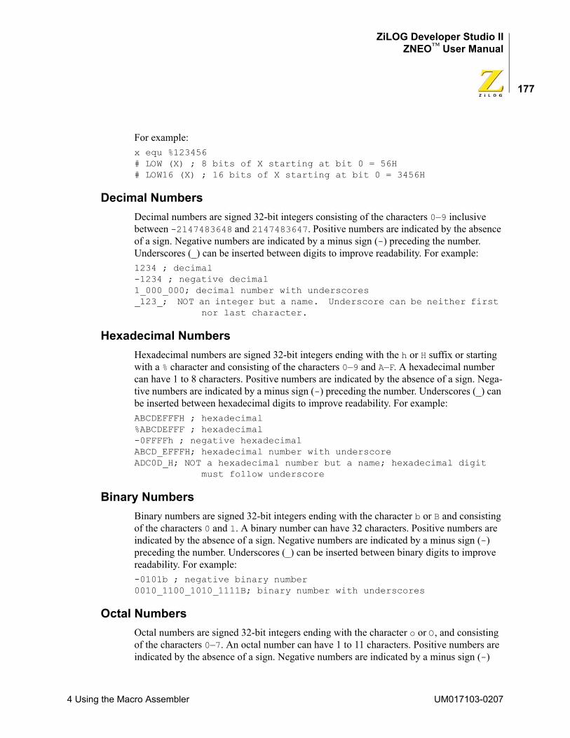
ZiLOG Developer Studio IIZNEO™ User Manual
177
For example:x equ %123456# LOW (X) ; 8 bits of X starting at bit 0 = 56H # LOW16 (X) ; 16 bits of X starting at bit 0 = 3456H
Decimal NumbersDecimal numbers are signed 32-bit integers consisting of the characters 0–9 inclusive between -2147483648 and 2147483647. Positive numbers are indicated by the absence of a sign. Negative numbers are indicated by a minus sign (-) preceding the number. Underscores (_) can be inserted between digits to improve readability. For example:1234 ; decimal -1234 ; negative decimal 1_000_000; decimal number with underscores _123_; NOT an integer but a name. Underscore can be neither first
nor last character.
Hexadecimal NumbersHexadecimal numbers are signed 32-bit integers ending with the h or H suffix or starting with a % character and consisting of the characters 0–9 and A–F. A hexadecimal number can have 1 to 8 characters. Positive numbers are indicated by the absence of a sign. Nega-tive numbers are indicated by a minus sign (-) preceding the number. Underscores (_) can be inserted between hexadecimal digits to improve readability. For example:ABCDEFFFH ; hexadecimal %ABCDEFFF ; hexadecimal -0FFFFh ; negative hexadecimal ABCD_EFFFH; hexadecimal number with underscore ADC0D_H; NOT a hexadecimal number but a name; hexadecimal digit
must follow underscore
Binary NumbersBinary numbers are signed 32-bit integers ending with the character b or B and consisting of the characters 0 and 1. A binary number can have 32 characters. Positive numbers are indicated by the absence of a sign. Negative numbers are indicated by a minus sign (-) preceding the number. Underscores (_) can be inserted between binary digits to improve readability. For example:-0101b ; negative binary number 0010_1100_1010_1111B; binary number with underscores
Octal NumbersOctal numbers are signed 32-bit integers ending with the character o or O, and consisting of the characters 0–7. An octal number can have 1 to 11 characters. Positive numbers are indicated by the absence of a sign. Negative numbers are indicated by a minus sign (-)
4 Using the Macro Assembler UM017103-0207
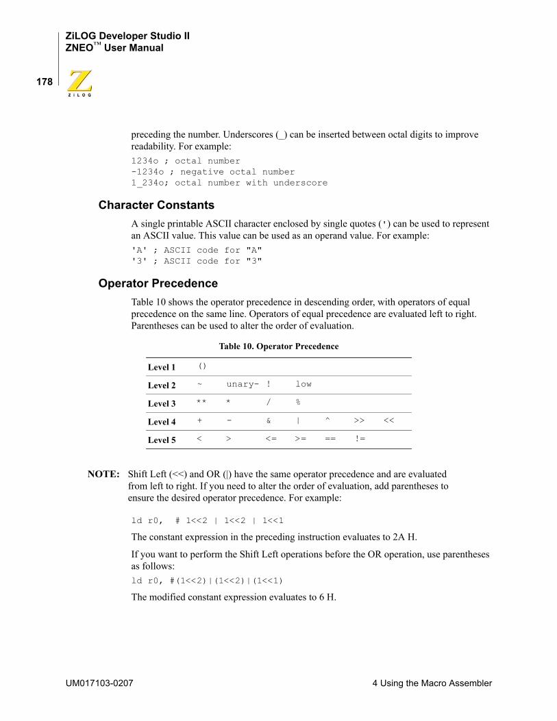
ZiLOG Developer Studio IIZNEO™ User Manual
178
preceding the number. Underscores (_) can be inserted between octal digits to improve readability. For example:1234o ; octal number -1234o ; negative octal number1_234o; octal number with underscore
Character ConstantsA single printable ASCII character enclosed by single quotes (') can be used to represent an ASCII value. This value can be used as an operand value. For example:'A' ; ASCII code for "A" '3' ; ASCII code for "3"
Operator PrecedenceTable 10 shows the operator precedence in descending order, with operators of equal precedence on the same line. Operators of equal precedence are evaluated left to right. Parentheses can be used to alter the order of evaluation.
NOTE: Shift Left (<<) and OR (|) have the same operator precedence and are evaluated from left to right. If you need to alter the order of evaluation, add parentheses to ensure the desired operator precedence. For example:
ld r0, # 1<<2 | 1<<2 | 1<<1
The constant expression in the preceding instruction evaluates to 2A H.
If you want to perform the Shift Left operations before the OR operation, use parentheses as follows:ld r0, #(1<<2)|(1<<2)|(1<<1)
The modified constant expression evaluates to 6 H.
Table 10. Operator Precedence
Level 1 ()
Level 2 ~ unary- ! low
Level 3 ** * / %
Level 4 + - & | ^ >> <<
Level 5 < > <= >= == !=
UM017103-0207 4 Using the Macro Assembler
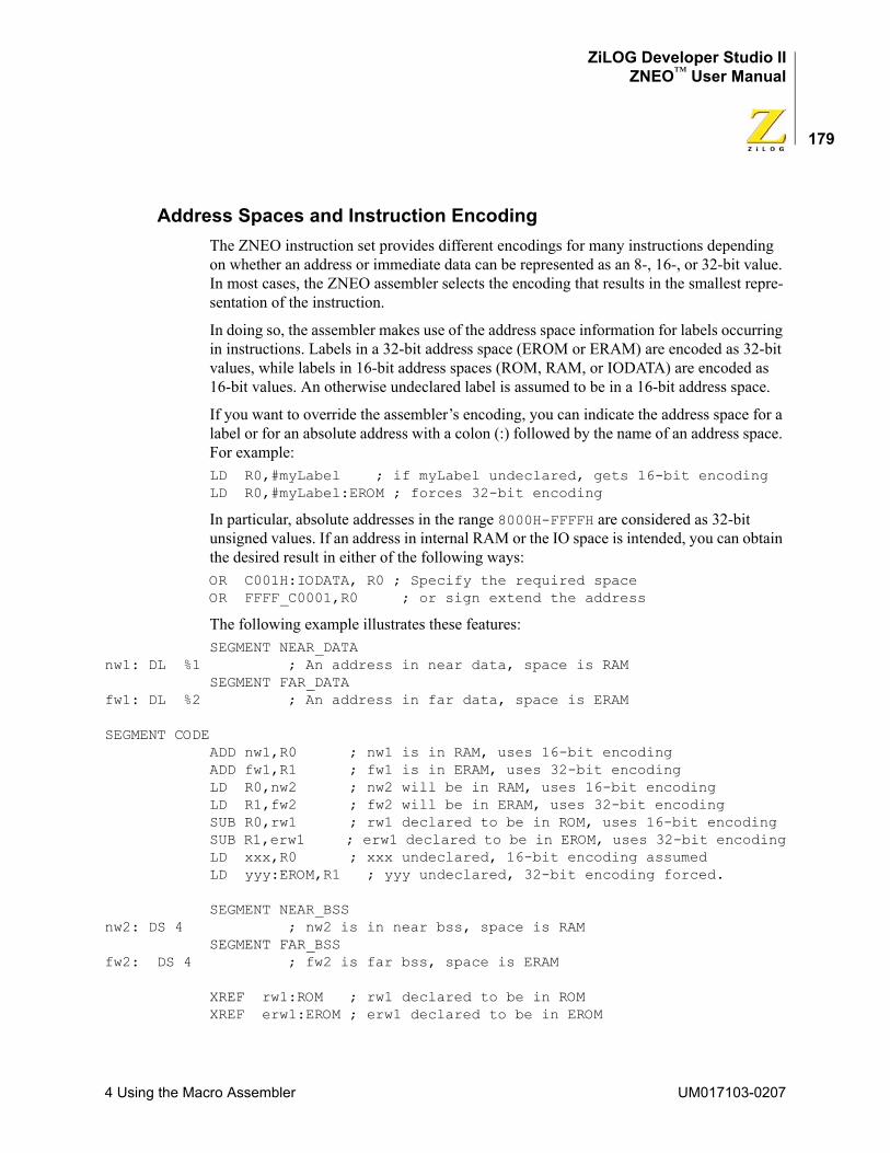
ZiLOG Developer Studio IIZNEO™ User Manual
179
Address Spaces and Instruction EncodingThe ZNEO instruction set provides different encodings for many instructions depending on whether an address or immediate data can be represented as an 8-, 16-, or 32-bit value. In most cases, the ZNEO assembler selects the encoding that results in the smallest repre-sentation of the instruction.
In doing so, the assembler makes use of the address space information for labels occurring in instructions. Labels in a 32-bit address space (EROM or ERAM) are encoded as 32-bit values, while labels in 16-bit address spaces (ROM, RAM, or IODATA) are encoded as 16-bit values. An otherwise undeclared label is assumed to be in a 16-bit address space.
If you want to override the assembler’s encoding, you can indicate the address space for a label or for an absolute address with a colon (:) followed by the name of an address space. For example:LD R0,#myLabel ; if myLabel undeclared, gets 16-bit encodingLD R0,#myLabel:EROM ; forces 32-bit encoding
In particular, absolute addresses in the range 8000H-FFFFH are considered as 32-bit unsigned values. If an address in internal RAM or the IO space is intended, you can obtain the desired result in either of the following ways:OR C001H:IODATA, R0 ; Specify the required spaceOR FFFF_C0001,R0 ; or sign extend the address
The following example illustrates these features:SEGMENT NEAR_DATA
nw1: DL %1 ; An address in near data, space is RAMSEGMENT FAR_DATA
fw1: DL %2 ; An address in far data, space is ERAM
SEGMENT CODEADD nw1,R0 ; nw1 is in RAM, uses 16-bit encodingADD fw1,R1 ; fw1 is in ERAM, uses 32-bit encodingLD R0,nw2 ; nw2 will be in RAM, uses 16-bit encodingLD R1,fw2 ; fw2 will be in ERAM, uses 32-bit encodingSUB R0,rw1 ; rw1 declared to be in ROM, uses 16-bit encodingSUB R1,erw1 ; erw1 declared to be in EROM, uses 32-bit encodingLD xxx,R0 ; xxx undeclared, 16-bit encoding assumedLD yyy:EROM,R1 ; yyy undeclared, 32-bit encoding forced.
SEGMENT NEAR_BSSnw2: DS 4 ; nw2 is in near bss, space is RAM
SEGMENT FAR_BSSfw2: DS 4 ; fw2 is far bss, space is ERAM
XREF rw1:ROM ; rw1 declared to be in ROMXREF erw1:EROM ; erw1 declared to be in EROM
4 Using the Macro Assembler UM017103-0207
ZiLOG Developer Studio IIZNEO™ User Manual
180
Register Lists for PUSHM and POPM InstructionsThe ZNEO processor provides the PUSHM and POPM instructions to push or pop multiple registers. (Actually, the ZNEO processor provides the PUSHMHI, PUSHMLO, POPMHI, and POPMLO instructions, which each push or pop half the register set.The ZNEO assembler accepts PUSHM and POPM and generates the lower level instructions.) The list of registers to be pushed or popped can be expressed either as a register list or as an immediate value. If an immediate value is used, the least significant bit represents R0, and the most signifi-cant bit represents R15. The following examples illustrate the syntax for register lists:
myFunction:PUSHM <R0-R2,R8,R12> ; Save registers R0,R1,R2,R8, and R12 ; Code for myFunction POPM <R0-R2,R8,R12> ; Restore RegistersRET ; and return
; The same example, using immediate values:hisFunction:
PUSHM #1107H ; Save registers R0,R1,R2,R8, and R12 ; Code for hisFunction POPM #1107H ; Restore RegistersRET ; and return
; The same example, using equates:RegList EQU "<R0-R2,R8,R12>"herFunction:
PUSHM RegList ; Save registers ; Code for herFunction POPM RegList ; Restore RegistersRET ; and return
Instruction AlignmentBecause all ZNEO instructions must be aligned to an even address, the ZNEO assembler implicitly inserts an ALIGN directive in front of each instruction. Thus, the following example assembles correctly:; Some codeRET
_L1: DW %1234 ; Some data, perhaps used by previous routineDB %3 ; Warning, next address is odd
myFunction: ; OK, implicitly aligned to next even addressLINK #%20
Of course, it does no harm to insert an ALIGN 2 or a .EVEN directive ahead of a function, just to be safe.
UM017103-0207 4 Using the Macro Assembler
ZiLOG Developer Studio IIZNEO™ User Manual
181
DIRECTIVESDirectives control the assembly process by providing the assembler with commands and information. These directives are instructions to the assembler itself and are not part of the microprocessor instruction set. Each of the supported assembler directives is described in the following sections:
• “ALIGN” on page 181
• “.COMMENT” on page 182
• “CPU” on page 182
• “Data Directives” on page 182
• “DEFINE” on page 185
• “DS” on page 186
• “END” on page 186
• “EQU” on page 187
• “INCLUDE” on page 187
• “LIST” on page 188
• “NOLIST” on page 188
• “ORG” on page 188
• “SEGMENT” on page 189
• “.SHORT_STACK_FRAME” on page 189
• “TITLE” on page 190
• “VAR” on page 190
• “VECTOR” on page 191
• “XDEF” on page 192
• “XREF” on page 192
• “Structures and Unions in Assembly Code” on page 192
ALIGNForces the object following to be aligned on a byte boundary that is a multiple of <value>.
Synonym
.align
Syntax
<align_directive> = > ALIGN <value>
4 Using the Macro Assembler UM017103-0207
ZiLOG Developer Studio IIZNEO™ User Manual
182
Example
ALIGN 2 DW EVEN_LABEL
.COMMENTThe .COMMENT assembler directive classifies a stream of characters as a comment.
The .COMMENT assembler directive causes the assembler to treat an arbitrary stream of characters as a comment. The delimiter can be any printable ASCII character. The assembler treats as comments all text between the initial and final delimiter, as well as all text on the same line as the final delimiter.
You must not use a label on this directive.
Synonym
COMMENT
Syntax
.COMMENT delimiter [ text ] delimiter
Example
.COMMENT $ An insightful comment of great meaning $
This text is a comment, delimited by a dollar sign, and spanning multiple source lines. The dollar sign ($) is a delimiter that marks the line as the end of the comment block.
CPUDefines to the assembler which member of the ZNEO family is targeted. From this direc-tive, the assembler can determine which instructions are legal as well as the locations of the interrupt vectors within the ROM space, __VECTOR segment.
NOTE: The CPU directive is used to determine the physical location of the interrupt vectors.
Syntax
<cpu_definition> = > CPU = <cpu_name>
Example
CPU = Z16F2811
Data DirectivesData directives allow you to reserve space for specified types of data.
UM017103-0207 4 Using the Macro Assembler
ZiLOG Developer Studio IIZNEO™ User Manual
183
Syntax
<data directive> = > <type> <value_list> <type> => DB => DL => DW => DW24 => BLKB => BLKL => BLKW <value_list> => <value> => <value_list>,<value> <value> => <expression>|<string_const>
BLKB Declaration TypeSyntax
BLKB count [, <init_value>]
Examples
BLKB 16 ; Allocate 16 uninitialized bytes. BLKB 16, -1 ; Allocate 16 bytes and initialize them to -1.
BLKL Declaration TypeSyntax
BLKL count [, <init_value>]
Examples
BLKL 16 ; Allocate 16 uninitialized longs. BLKL 16, -1 ; Allocate 16 longs and initialize them to -1.
BLKW Declaration TypeSyntax
BLKW count [, <init_value>]
Examples
BLKW 16 ; Allocate 16 uninitialized words. BLKW 16, -1 ; Allocate 16 words and initialize them to -1.
DB Declaration TypeSynonyms
.byte, .ascii, DEFB, FCB, STRING, .STRING, byte, .asciz
4 Using the Macro Assembler UM017103-0207
ZiLOG Developer Studio IIZNEO™ User Manual
184
Syntax
DB byte data (8 bits)
Examples
DB "Hello World" ; Reserve and initialize 11 bytes. DB 1,2 ; Reserve 2 bytes. Initialize the ; first word with a 1 and the second with a 2. DB %12 ; Reserve 1 byte. Initialize it with %12.
NOTE: There is no trailing null for the DB declaration type. A trailing null is added for .asciz declaration types.
DL Declaration TypeSynonyms
.long, long
Syntax
DL long (32 bits)
Examples
DL 1,2 ; Reserve 2 long words. Initialize the ; first with a 1 and last with a 2. DL %12345678 ; Reserve space for 1 long word and ; initialize it to %12345678.
DW Declaration TypeSynonyms
.word, word, .int
Syntax
DW word data (16 bits)
Examples
DW "Hello World" ; Reserve and initialize 11 words. DW "Hello" ; Reserve and initialize 5 words. DW 1,2 ; Reserve 2 words. Initialize the ; first word with a 1 and the second with a 2. DW %1234 ; Reserve 1 word and initialize it with %1234.
NOTE: There is no trailing null for the DW declaration type. Each letter gets 16 bits with the upper 8 bits zero.
UM017103-0207 4 Using the Macro Assembler
ZiLOG Developer Studio IIZNEO™ User Manual
185
DW24 Declaration TypeSynonyms
.word24, .trio, .DW24
Syntax
DW24 word data (24 bits)
Examples
dw24 %123456 ; Reserve one 24-bit entity and initialize it with %123456.trio %789abc ; Reserve one 24-bit entity and initialize it with %798abc
DEFINEDefines a segment with its associated address space, alignment, and origin. You must define a segment before you can use it, unless it is a predefined segment. If a clause is not given, use the default for that definition. For more information on the SEGMENT directive, see “SEGMENT” on page 189. For a list of predefined segments, see “Predefined Seg-ments” on page 168.
Synonym
.define
Syntax
<segment_definition> => DEFINE<ident>[<space_clause>][align_clause>][<org_clause>]
Examples
DEFINE near_code ; Uses the defaults of the current ; space, byte alignment and relocatable. DEFINE irq_table,ORG=%FFF8 ; Uses current space, byte alignment, ; and absolute starting address at ; memory location %FFF8.
ALIGN ClauseAllows you to select the alignment boundary for a segment. The linker places modules in this segment on the defined boundary. The multiple, given in bytes, must be a power of two (1, 2, 4, 8, and so on).
Syntax
<align_clause> => ,ALIGN = <int_const>
Example
DEFINE fdata,SPACE = ERAM,ALIGN = 2; Aligns on 2-byte boundary, relocatable.
4 Using the Macro Assembler UM017103-0207
ZiLOG Developer Studio IIZNEO™ User Manual
186
ORG ClauseAllows you to specify where the segment is to be located, making the segment an absolute segment. The linker places the segment at the memory location specified by the ORG. The default is no ORG, and thus the segment is relocatable.
Syntax
<org_clause> => ,ORG = <int_const>
Synonym
ORIGIN
Example
DEFINE near_code,ORG = %FFF8; Uses current space, byte alignment, and absolute starting ; address at memory location %FFF8.
SPACE ClauseA SPACE clause defines the address space in which the segment resides. The linker groups together segments with the same space identification. See Table 8, “ZNEO Address Spaces,” on page 168 for available spaces.
Syntax
<space_clause> => ,SPACE = <indent>
Example
DEFINE fdata,SPACE = ERAM,ALIGN = 2; Aligns on a 2-byte boundary, relocatable.
DSDefines storage locations that do not need to be initialized.
Synonym
.block
Syntax
<define_storage> => DS <value>
Example
NAME DS 10 ; Reserve 10 bytes of storage.
ENDInforms the assembler of the end of the source input file. If the operand field is present, it defines the start address of the program. During the linking process, only one module can
UM017103-0207 4 Using the Macro Assembler
ZiLOG Developer Studio IIZNEO™ User Manual
187
define the start address; otherwise, an error results. The END directive is optional for those modules that do not define the start address.
Synonym
.end
Syntax
<end_directive> => END[<expression>]
Example
END _start ; Use the value of _start as the program start address.
EQUAssigns symbolic names to numeric or string values. Any name used to define an equate must not have been previously defined. Other equates and label symbols are allowed in the expression, provided they are previously defined.
Synonyms
.equ, .EQU, EQUAL, .equal
Syntax
<label> EQU <expression>
Examples
length EQU 6 ; 1st dimension of rectanglewidth EQU 11 ; 2nd dimension of rectanglearea EQU length * width ; area of the rectangle
reg EQU r7 ; symbolic name of a register
INCLUDEAllows the insertion of source code from another file into the current source file during assembly. The included file is assembled into the current source file immediately after the directive. When the EOF (End of File) of the included file is reached, the assembly resumes on the line after the INCLUDE directive.
The file to include is named in the string constant after the INCLUDE directive. The file name can contain a path. If the file does not exist, an error results, and the assembly is aborted. A recursive INCLUDE also results in an error.
INCLUDE files are contained in the listing (.lst) file unless a NOLIST directive is active.
Synonyms
.include, .copy, COPY
4 Using the Macro Assembler UM017103-0207
ZiLOG Developer Studio IIZNEO™ User Manual
188
Syntax
<include_directive> => INCLUDE[<string_const>]
Examples
INCLUDE "calc.h" ; include calc header file INCLUDE "\test\calc.h" ; contains a path name INCLUDE calc.h ; ERROR, use string constant
LISTInstructs the assembler to send output to the listing file. This mode stays in effect until a NOLIST directive is encountered. No operand field is allowed. This mode is the default mode.
Synonyms
.list, .LIST
Syntax
<list_directive> => LIST
Example
LIST NOLIST
NOLISTTurns off the generation of the listing file. This mode remains in effect until a LIST directive is encountered. No operand is allowed.
Synonym
.NOLIST
Syntax
<nolist_directive> => NOLIST
Example
LIST NOLIST
ORGThe ORG assembler directive sets the assembler location counter to a specified value in the address space of the current segment.
The ORG directive must be followed by an integer constant, which is the value of the new origin.
UM017103-0207 4 Using the Macro Assembler
ZiLOG Developer Studio IIZNEO™ User Manual
189
Synonyms
ORIGIN, .ORG
Syntax
<org_directive> => ORG <int_const>
ExamplesORG %1000 ; Sets the location counter at %1000 in the address space of current segmentORG LOOP ; ERROR, use an absolute constant
On encountering the ORG assembler directive, the assembler creates a new absolute seg-ment with a name starting with $$$org. This new segment is placed in the address space of the current segment, with origin at the specified value and alignment as 1.
NOTE: ZiLOG recommends that segments requiring the use of ORG be declared as absolute segments from the outset by including an ORG clause in the DEFINE directive for the segment.
SEGMENTSpecifies entry into a previously defined segment.
The SEGMENT directive must be followed by the segment identifier. The default segment is used until the assembler encounters a SEGMENT directive. The internal assembler program counter is reset to the previous program counter of the segment when a SEGMENT directive is encountered. See Table 9, “Predefined Segments,” on page 169 for the names of pre-defined segments.
Synonyms
SECTION
Syntax
<segment_directive> => SEGMENT <ident>
Example
SEGMENT code ; predefined segment DEFINE data ; user-defined
.SHORT_STACK_FRAMEThe ZNEO LD and LEA instructions permit a special encoding when an argument is an offset from the frame pointer and the offset can be expressed as a signed 6-bit value (-32 to +31). Normally, the ZNEO assembler chooses the smaller encoding whenever possible; otherwise, the assembler chooses the more general 14-bit encoding.
4 Using the Macro Assembler UM017103-0207
ZiLOG Developer Studio IIZNEO™ User Manual
190
Also, when the ZNEO assembler encounters a LINK instruction allocating more than 256 bytes of stack frame, it silently substitutes a sequence of LINK and LEA or SUB instruc-tions to obtain the desired result.
For especially tight code, you might prefer to be alerted with an error message when an offset from the frame pointer on an LD or LEA instruction cannot be encoded in a 6-bit field or when the stack size requested in a LINK instruction cannot be encoded in the 8-bit field allowed for a LINK instruction. The .SHORT_STACK_FRAME directive supports such a preference.
Syntax
<shortfp_directive> => .SHORT_STACK_FRAME ON|OFF
Example
.SHORT_STACK_FRAME ON ; Turn short stack frames on ; Section of code that needs to be very tight .SHORT_STACK_FRAME OFF ; Turn short stack frames off
TITLECauses a user-defined TITLE to be displayed in the listing file. The new title remains in effect until the next TITLE directive. The operand must be a string constant.
Synonym
.title
Syntax
<title_directive> => TITLE <string_const>
Example
TITLE "My Title"
VAR
The VAR directive works just like an EQU directive except you are allowed to change the value of the label. In the following example, STRVAR is assigned three different values. This would cause an error if EQU was used instead of VAR.
Synonym
.VAR, SET, .SET
Syntax
<label> VAR <expression>
Example
A 6 SEGMENT NEAR_DATA
UM017103-0207 4 Using the Macro Assembler
ZiLOG Developer Studio IIZNEO™ User Manual
191
A 7 ALIGN 2 000000FF A 8 STRVAR VAR FFH000000 FF A 9 DB STRVAR A 10 SEGMENT ROM_TEXT000000 A 11 L__0:000000 4641494C 4544 A 12 DB "FAILED"000006 00 A 13 DB 0 A 14 SEGMENT NEAR_DATA A 15 ALIGN 2 00000000 A 16 STRVAR VAR L__0 A 17 000002 A 18 _fail_str:000002 00 A 19 DB STRVAR A 20 SEGMENT ROM_TEXT000007 A 21 L__1:000007 50415353 4544 A 22 DB "PASSED"00000D 00 A 23 DB 0 00000007 A 24 STRVAR VAR L__1 A 25 SEGMENT NEAR_DATA A 26 ALIGN 2000004 A 27 _pass_str:000004 07 A 28 DB STRVAR
VECTORInitializes an interrupt or reset vector to a program address.
The CPU directive is used to determine the physical location of the interrupt vectors.
Syntax
<vector_directive> => VECTOR <vector name> = <expression>
<vector name> specifies which vector is being selected. For ZNEO, <vector name> must be one of the following:
ADCC0C1C2C3I2CP0ADP1ADP2ADP3ADP4ADP5ADP6AD
P7ADPWM_FAULTPWM_TIMERRESETSPISYSEXCTIMER0TIMER1TIMER2UART0_RXUART0_TXUART1_RXUART1_TX
4 Using the Macro Assembler UM017103-0207
ZiLOG Developer Studio IIZNEO™ User Manual
192
Examples
VECTOR SPI = spi_handler VECTOR P2AD = p2ad_handler
XDEFDefines a list of labels in the current module as an external symbol that are to be made publicly visible to other modules at link time. The operands must be labels that are defined somewhere in the assembly file.
Synonyms
.global, GLOBAL, .GLOBAL, .public, .def, public
Syntax
<xdef_directive> => XDEF <ident list>
Examples
XDEF label XDEF label1,label2,label3
XREFSpecifies that a list of labels in the operand field are defined in another module. The reference is resolved by the linker. The labels must not be defined in the current module. This directive optionally specifies the address space in which the label resides.
Synonyms
.extern, EXTERN, EXTERNAL, .ref
Syntax
<xref_directive> => XREF <ident_space_list> <ident_space_list> => <ident_space> => <ident_space_list>, <ident_space> <ident_space> => <ident> [:<space>]
Examples
XREF label XREF label1,label2,label3 XREF label:ROM
Structures and Unions in Assembly CodeThe assembler provides a set of directives to group data elements together, similar to high-level programming language constructs like a C structure or a Pascal record. These direc-tives allow you to declare a structure or union type consisting of various elements, assign
UM017103-0207 4 Using the Macro Assembler
ZiLOG Developer Studio IIZNEO™ User Manual
193
labels to be of previously declared structure or union type, and provide multiple ways to access elements at an offset from such labels.
The assembler directives associated with structure and union support are listed in the fol-lowing table:
.STRUCT and .ENDSTRUCT DirectivesA structure is a collection of various elements grouped together under a single name for convenient handling. The .STRUCT and .ENDSTRUCT directives can be used to define the layout for a structure in assembly by identifying the various elements and their sizes. The .STRUCT directive assigns symbolic offsets to the elements of a structure. It does not allo-cate memory. It merely creates a symbolic template that can be used repeatedly.
The .STRUCT and .ENDSTRUCT directives have the following form:
[stag] .STRUCT [offset | : parent]
[name_1] DS count1
[name_2] DS count2
[tname] .TAG stagx [count]
...
[name_n] DS count3
[ssize] .ENDSTRUCT [stag]
The label stag defines a symbol to use to reference the structure; the expression offset, if used, indicates a starting offset value to use for the first element encountered; otherwise, the starting offset defaults to zero.
If parent is specified rather than offset, the parent must be the name of a previously defined structure, and the offset is the size of the parent structure. In addition, each name in the parent structure is inserted in the new structure.
Each element can have an optional label, such as name_1, which is assigned the value of the element’s offset into the structure and which can be used as the symbolic offset. If stag is missing, these element names become global symbols; otherwise, they are referenced
Assembler Directive Description.STRUCT Group data elements in a structure type.ENDSTRUCT Denotes end of structure or union type.UNION Group data elements in a union type.TAG Associate label with a structure or union type.WITH A section in which the specified label or structure tag is implicit.ENDWITH Denotes end of with section
4 Using the Macro Assembler UM017103-0207
ZiLOG Developer Studio IIZNEO™ User Manual
194
using the syntax stag.name. The directives following the optional label can be any space reserving directive such as DS, or the .TAG directive (defined below), and the structure offset is adjusted accordingly.
The label ssize, if provided, is a label in the global name space and is assigned the size of the structure.
If a label stag is specified with the .ENDSTRUCT directive, it must match the label that is used for the .STRUCT directive. The intent is to allow for code readability with some checking by the assembler.
An example structure definition is as follows:
DATE .STRUCT
MONTH DS 1
DAY DS 1
YEAR DS 2
DSIZE .ENDSTRUCT DATE
NOTE: Directives allowed between .STRUCT and .ENDSTRUCT are directives that specify size, principally DS, ALIGN, ORG, and .TAG and their aliases. Also, BLKB, BLKW, and BLKL directives with one parameter are allowed because they indicate only size.
The following directives are not allowed within .STRUCT and .ENDSTRUCT:
• Initialization directives (DB, DW, DL, DF, and DD) and their aliases
• BLKB, BLKW, and BLKL with two parameters because they perform initialization
• Equates (EQU and SET)
• Macro definitions (MACRO)
• Segment directives (SEGMENT and FRAME)
• Nested .STRUCT and .UNION directives
• CPU instructions (for example, LD and NOP)
.TAG DirectiveThe .TAG assembler declares or assigns a label to have a structure type. This directive can also be used to define a structure/union element within a structure. The .TAG directive does not allocate memory.
The .TAG directive to define a structure/union element has the following form:
[stag] .STRUCT [offset | : parent]
[name_1] DS count1
UM017103-0207 4 Using the Macro Assembler
ZiLOG Developer Studio IIZNEO™ User Manual
195
[name_2] DS count2
...
[tname] .TAG stagx [count]
...
[ssize] .ENDSTRUCT [stag]
The .TAG directive to assign a label to have a structure type has the following form:
[tname] .TAG stag ; Apply stag to tname
[tname] DS ssize ; Allocate space for tname
Once applied to label tname, the individual structure elements are applied to tname to pro-duce the desired offsets using tname as the structure base. For example, the label tname.name_2 is created and assigned the value tname + stag.name_2. If there are any alignment requirements with the structure, the .TAG directive attaches the required alignment to the label. The optional count on the .TAG directive is meaningful only inside a structure definition and implies an array of the .TAG structure.
NOTE: Keeping the space allocation separate allows you to place the .TAG declarations that assign structure to a label in the header file in a similar fashion to the .STRUCT and XREF directives. You can then include the header file in multiple source files wherever the label is used. Make sure to perform the space allocation for the label in only one source file.
Examples of the .TAG directive are as follows:DATE .STRUCTMONTH DS 1DAY DS 1YEAR DS 2DSIZE .ENDSTRUCT DATE
NAMELEN EQU 30
EMPLOYEE .STRUCTNAME DS NAMELENSOCIAL DS 10START .TAG DATESALARY DS 1ESIZE .ENDSTRUCT EMPLOYEE
NEWYEARS .TAG DATENEWYEARS DS DSIZE
The .TAG directive in the last example above creates the symbols NEWYEARS.MONTH, NEWYEARS.DAY, and NEWYEARS.YEAR. The space for NEWYEARS is allocated by the DS directive.
4 Using the Macro Assembler UM017103-0207
ZiLOG Developer Studio IIZNEO™ User Manual
196
.UNION DirectiveThe .UNION directive is similar to the .STRUCT directive, except that the offset is reset to zero on each label. A .UNION directive cannot have an offset or parent union. The key-word to terminate a .UNION definition is .ENDSTRUCT.
The .UNION directive has the following form:
[stag] .UNION
[name_1] DS count1
[name_2] DS count2
[tname] .TAG stagx [count]
...
[name_n] DS count3
[ssize] .ENDSTRUCT [stag]
An example of the .UNION directive usage is as follows:BYTES .STRUCTB0 DS 1B1 DS 1B2 DS 1B3 DS 1 BSIZE .ENDSTRUCT BYTES
LONGBYTES .UNIONLDATA BLKL 1BDATA .TAG BYTESLSIZE .ENDSTRUCT LONGBYTES
.WITH and .ENDWITH DirectivesUsing the fully qualified names for fields within a structure can result in very long names. The .WITH directive allows the initial part of the name to be dropped.
The .WITH and .ENDWITH directives have the following form:
.WITH name
; directives
.ENDWITH [name]
The identifier name may be the name of a previously defined .STRUCT or .UNION, or an ordinary label to which a structure has been attached using a .TAG directive. It can also be the name of an equate or label with no structure attached. Within the .WITH section, the assembler attempts to prepend “name.” to each identifier encountered, and selects the
UM017103-0207 4 Using the Macro Assembler
ZiLOG Developer Studio IIZNEO™ User Manual
197
modified name if the result matches a name created by the .STRUCT, .UNION, or .TAG directives.
The .WITH directives can be nested, in which case the search is from the deepest level of nesting outward. In the event that multiple names are found, a warning is generated and the first such name is used.
If name is specified with the .ENDWITH directive, the name must match that used for the .WITH directive. The intent is to allow for code readability with some checking by the assembler.
For example, the COMPUTE_PAY routine below:COMPUTE_PAY:; Enter with pointer to an EMPLOYEE in R2, days in R1; Return with pay in R0,R1
LD R0,EMPLOYEE.SALARY(R2) MULT RR0 RET
could be written using the .WITH directive as follows:COMPUTE_PAY:; Enter with pointer to an EMPLOYEE in R2, days in R1; Return with pay in R0,R1
.WITH EMPLOYEE LD R0, SALARY(R2) MULT RR0 RET .ENDWITH EMPLOYEE
CONDITIONAL ASSEMBLYConditional assembly is used to control the assembly of blocks of code. Entire blocks of code can be enabled or disabled using conditional assembly directives.
The following conditional assembly directives are allowed:
• IF
• IFDEF
• IFSAME
• IFMA
Any symbol used in a conditional directive must be previously defined by an EQU or VAR directive. Relational operators can be used in the expression. Relational expressions eval-uate to 1 if true, and 0 if false.
4 Using the Macro Assembler UM017103-0207
ZiLOG Developer Studio IIZNEO™ User Manual
198
If a condition is true, the code body is processed. Otherwise, the code body after an ELSE is processed, if included.
The ELIF directive allows a case-like structure to be implemented.
NOTE: Conditional assembly can be nested.
Conditional Assembly Directives• “IF” on page 198
• “IFDEF” on page 199
• “IFSAME” on page 199
• “IFMA” on page 200
IFEvaluates a Boolean expression. If the expression evaluates to 0, the result is false; otherwise, the result is true.
Synonyms
.if, .IF, IFN, IFNZ, COND, IFTRUE, IFNFALSE, .IFTRUE
Syntax
IF [<cond_expression> <code_body>] [ELIF <cond_expression> <code_body>] [ELSE <code_body>] ENDIF
Example
IF XYZ ; process code body if XYZ is not 0 . . . <Code Body> . . ENDIFIF XYZ !=3 ; code body 1 if XYZ is not 3 . . . <Code Body 1> . . .
UM017103-0207 4 Using the Macro Assembler
ZiLOG Developer Studio IIZNEO™ User Manual
199
ELIF ABC ; XYZ=3 and ABC is not 0, . . . <Code Body 2> . . .ELSE ; otherwise code body 3 . . . <Code Body 3> . . . ENDIF
IFDEFChecks for label definition. Only a single label can be used with this conditional. If the label is defined, the result is true; otherwise, the result if false.
Syntax
IFDEF <label> <code_body> [ELSE <code_body>] ENDIF
Example
IFDEF XYZ ; process code body if XYZ is defined . . . <Code Body> . . . ENDIF
IFSAMEChecks to see if two string constants are the same. If the strings are the same, the result is true; otherwise, the result is false. If the strings are not enclosed by quotes, the comma is used as the separator.
4 Using the Macro Assembler UM017103-0207
ZiLOG Developer Studio IIZNEO™ User Manual
200
Syntax
IFSAME <string_const> , <string_const> <code_body> [ELSE <code_body>] ENDIF
IFMAUsed only within a macro, this directive checks to determine if a macro argument has been defined. If the argument is defined, the result is true. Otherwise, the result is false. If <arg_number> is 0, the result is TRUE if no arguments were provided; otherwise, the result is FALSE.
NOTE: IFMA refers to argument numbers that are one based (that is, the first argument is numbered one).
Syntax
IFMA <arg_number> <code_body> [ELSE <code_body>] ENDIF
MACROSMacros allow a sequence of one or more assembly source lines to be represented by a sin-gle assembler symbol. In addition, arguments can be supplied to the macro in order to specify or alter the assembler source lines generated once the macro is expanded. The fol-lowing sections describe how to define and invoke macros.
Macro DefinitionA macro definition must precede the use of the macro. The macro name must be the same for both the definition and the ENDMACRO line. The argument list contains the formal argu-ments that are substituted with actual arguments when the macro is expanded. The argu-ments can be optionally prefixed with the substitution character (\) in the macro body.
During the invocation of the macro, a token substitution is performed, replacing the formal arguments (including the substitution character, if present) with the actual arguments.
Syntax
<macroname>[:]MACRO[<arg>(,<arg>)...] <macro_body> ENDMAC[RO]<macroname>
UM017103-0207 4 Using the Macro Assembler
ZiLOG Developer Studio IIZNEO™ User Manual
201
Example
store: MACRO reg1,reg2,reg3 ADD reg1,reg2 LD reg3,reg1 ENDMAC store
NOTE: The following example contains a subtle error:
BadMac MACRO a,b,cDL a,b,cMACEND BadMac
Recall that b and c are reserved words on ZNEO, used for condition codes on the JP instruction. Thus, they cannot be used as macro arguments. To avoid this and similar errors, it is recommended that you avoid single character names.
ConcatenationTo facilitate unambiguous symbol substitution during macro expansion, the concatenation character (&) can be suffixed to symbol names. The concatenation character is a syntactic device for delimiting symbol names that are points of substitution and is devoid of seman-tic content. The concatenation character, therefore, is discarded by the assembler, when the character has delimited a symbol name. For example:val_part1 equ 55hval_part2 equ 33h
The assembly is:value macro par1, par2
DB par1&_&par2macend
value val,part1value val,part2
The generated list file is: A 9 value val,part1000000 55 A+ 9 DB val_part1 A+ 9 macend A 10 value val,part2000001 33 A+ 10 DB val_part2 A+ 10 macend
Macro Invocation A macro is invoked by specifying the macro name and following the name with the desired arguments. Use commas to separate the arguments.
4 Using the Macro Assembler UM017103-0207
ZiLOG Developer Studio IIZNEO™ User Manual
202
Syntax
<macroname>[<arg>[(,<arg>)]...]
Example
store R1,R2,R3
This macro invocation causes registers R1 and R2 to be added and the result stored in reg-ister R3.
Local Macro Labels Local macro labels allow labels to be used within multiple macro expansions without duplication. When used within the body of a macro, symbols preceded by two dollar signs ($$) are considered local to the scope of the macro and therefore are guaranteed to be unique. The two dollars signs are replaced by an underscore followed by a macro invoca-tion number.
Syntax
$$ <label>
Example
LJMP: MACRO cc,label JP cc,$$lab JP label $$lab: ENDMAC
Optional Macro ArgumentsA macro can be defined to handle omitted arguments using the IFMA (if macro argument) conditional directive within the macro. The conditional directive can be used to detect if an argument was supplied with the invocation.
Example
MISSING_ARG: MACRO ARG0,ARG1,ARG2 IFMA 2 LD ARG0,ARG1 ELSE LD ARG0,ARG2 ENDIF ENDMACRO MISSING_ARG
Invocation
MISSING_ARG R1, ,R2 ; missing second arg
Result
LD R1,R2
UM017103-0207 4 Using the Macro Assembler
ZiLOG Developer Studio IIZNEO™ User Manual
203
NOTE: IFMA refers to argument numbers that are one based (that is, the first argument is numbered one).
Exiting a MacroThe MACEXIT directive is used to immediately exit a macro. No further processing is per-formed. However, the assembler checks for proper if-then conditional directives. A MACEXIT directive is normally used to terminate a recursive macro.
The following example is a recursive macro that demonstrates using MACEXIT to termi-nate the macro.
Example
RECURS_MAC: MACRO ARG1,ARG2 IF ARG1==0 MACEXIT ELSE RECURS_MAC ARG1-1, ARG2 DB ARG2 ENDIF ENDMACRO RECURS_MAC RECURS_MAC 1, ’a’
LABELSLabels are considered symbolic representations of memory locations and can be used to reference that memory location within an expression. See “Local Labels” on page 204 for the form of a legal label.
The following sections describe labels:
• “Anonymous Labels” on page 204
• “Local Labels” on page 204
• “Importing and Exporting Labels” on page 204
• “Label Spaces” on page 204
4 Using the Macro Assembler UM017103-0207
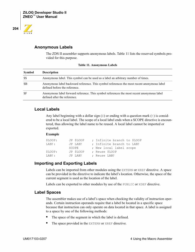
ZiLOG Developer Studio IIZNEO™ User Manual
204
Anonymous LabelsThe ZDS II assembler supports anonymous labels. Table 11 lists the reserved symbols pro-vided for this purpose.
Local LabelsAny label beginning with a dollar sign ($) or ending with a question mark (?) is consid-ered to be a local label. The scope of a local label ends when a SCOPE directive is encoun-tered, thus allowing the label name to be reused. A local label cannot be imported or exported.
Example
$LOOP: JP $LOOP ; Infinite branch to $LOOPLAB?: JP LAB? ; Infinite branch to LAB?
SCOPE ; New local label scope$LOOP: JP $LOOP ; Reuse $LOOPLAB?: JP LAB? ; Reuse LAB?
Importing and Exporting LabelsLabels can be imported from other modules using the EXTERN or XREF directive. A space can be provided in the directive to indicate the label’s location. Otherwise, the space of the current segment is used as the location of the label.
Labels can be exported to other modules by use of the PUBLIC or XDEF directive.
Label SpacesThe assembler makes use of a label’s space when checking the validity of instruction oper-ands. Certain instruction operands require that a label be located in a specific space because that instruction can only operate on data located in that space. A label is assigned to a space by one of the following methods:
• The space of the segment in which the label is defined.
• The space provided in the EXTERN or XREF directive.
Table 11. Anonymous Labels
Symbol Description
$$ Anonymous label. This symbol can be used as a label an arbitrary number of times.
$B Anonymous label backward reference. This symbol references the most recent anonymous label defined before the reference.
$F Anonymous label forward reference. This symbol references the most recent anonymous label defined after the reference.
UM017103-0207 4 Using the Macro Assembler
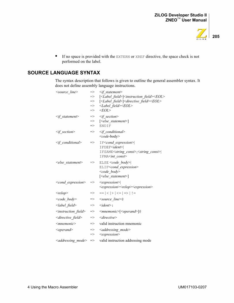
ZiLOG Developer Studio IIZNEO™ User Manual
205
• If no space is provided with the EXTERN or XREF directive, the space check is not performed on the label.
SOURCE LANGUAGE SYNTAXThe syntax description that follows is given to outline the general assembler syntax. It does not define assembly language instructions.<source_line> =>
=>=>=>=>
<if_statement>[<Label_field>]<instruction_field><EOL>[<Label_field>]<directive_field><EOL><Label_field><EOL><EOL>
<if_statement> =>=>=>
<if_section>[<else_statement>]ENDIF
<if_section> => <if_conditional><code-body>
<if_conditional> => IF<cond_expression>| IFDEF<ident>| IFSAME<string_const>,<string_const>| IFMA<int_const>
<else_statement> => ELSE <code_body>| ELIF<cond_expression> <code_body> [<else_statement>]
<cond_expression> => <expression>| <expression><relop><expression>
<relop> => == | < | > | <= | => | !=<code_body> => <source_line>@<label_field> => <ident>:<instruction_field> => <mnemonic>[<operand>]@<directive_field> => <directive><mnemonic> => valid instruction mnemonic<operand> =>
=><addressing_mode><expression>
<addressing_mode> => valid instruction addressing mode
4 Using the Macro Assembler UM017103-0207
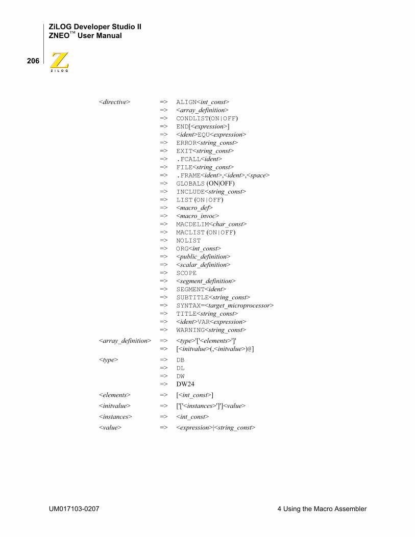
ZiLOG Developer Studio IIZNEO™ User Manual
206
<directive> =>=>=>=>=>=>=>=>=>=>=>=>=>=>=>=>=>=>=>=>=>=>=>=>=>=>=>=>=>
ALIGN<int_const><array_definition> CONDLIST(ON|OFF) END[<expression>] <ident>EQU<expression> ERROR<string_const> EXIT<string_const> .FCALL<ident> FILE<string_const> .FRAME<ident>,<ident>,<space> GLOBALS (ON|OFF) INCLUDE<string_const> LIST (ON|OFF) <macro_def> <macro_invoc> MACDELIM<char_const> MACLIST (ON|OFF) NOLIST ORG<int_const> <public_definition> <scalar_definition> SCOPE <segment_definition> SEGMENT<ident> SUBTITLE<string_const> SYNTAX=<target_microprocessor>TITLE<string_const> <ident>VAR<expression> WARNING<string_const>
<array_definition> =>=>
<type>'['<elements>']'[<initvalue>(,<initvalue>)@]
<type> =>=>=>=>
DBDLDWDW24
<elements> => [<int_const>]<initvalue> => ['['<instances>']']<value><instances> => <int_const><value> => <expression>|<string_const>
UM017103-0207 4 Using the Macro Assembler
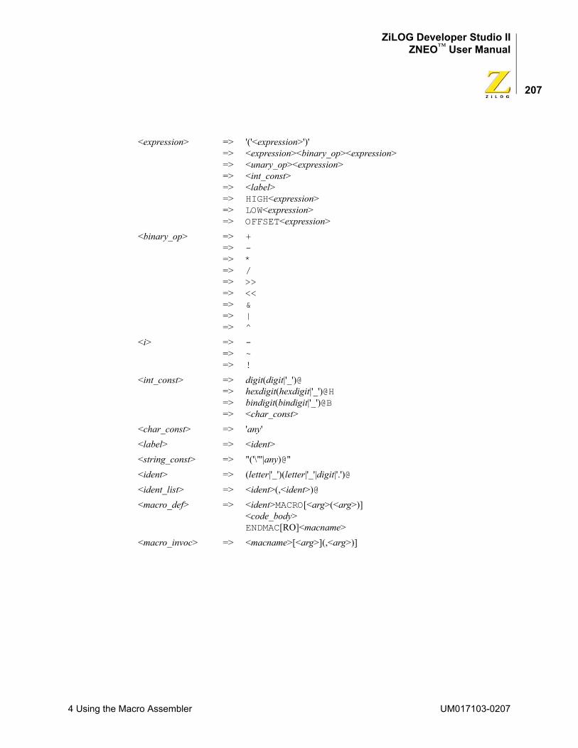
ZiLOG Developer Studio IIZNEO™ User Manual
207
<expression> =>=>=>=>=>=>=>=>
'('<expression>')'<expression><binary_op><expression> <unary_op><expression> <int_const> <label> HIGH<expression> LOW<expression> OFFSET<expression>
<binary_op> =>=>=>=>=>=>=>=>=>
+- * / >> << & | ^
<i> =>=>=>
- ~ !
<int_const> =>=>=>=>
digit(digit|'_')@ hexdigit(hexdigit|'_')@H bindigit(bindigit|'_')@B <char_const>
<char_const> => 'any'<label> => <ident><string_const> => "('\"'|any)@"<ident> => (letter|'_')(letter|'_'|digit|'.')@<ident_list> => <ident>(,<ident>)@<macro_def> => <ident>MACRO[<arg>(<arg>)]
<code_body> ENDMAC[RO]<macname>
<macro_invoc> => <macname>[<arg>](,<arg>)]
4 Using the Macro Assembler UM017103-0207
ZiLOG Developer Studio IIZNEO™ User Manual
208
WARNING AND ERROR MESSAGESThis section covers warning and error messages for the assembler.
400 Symbol already defined.
The symbol has been previously defined.
401 Syntax error.
General-purpose error when the assembler recognizes only part of a source line. The assembler might generate multiple syntax errors per source line.
402 Symbol XREF'd and XDEF'd.
Label previously marked as externally defined or referenced. This error occurs when an attempt is made to both XREF and XDEF a label.
403 Symbol not a segment.
The segment has not been previously defined or is defined as some other symbol type.
404 Illegal EQU.
The name used to define an equate has been previously defined or equates and label symbols in an equate expression have not been previously defined.
405 Label not defined.
The label has not been defined, either by an XREF or a label definition.
406 Illegal use of XREF's symbol.
XDEF defines a list of labels in the current module as an external symbol that are to be made publicly visible to other modules at link time; XREF specifies that a list of labels in the operand field are defined in another module.
<arg> => macro argument<public_definition> => PUBLIC<ident list>
EXTERN<ident list><scalar_definition> => <type>[<value>]<segment_definition>
=> DEFINE<ident>[<space_clause>][<align_clause>][<org_clause>]
<space_clause> => ,SPACE=<space><align_clause> => ,ALIGN=<int_const><org_clause> => ,ORG=<int_const><space> => (RAM|ROM|ERAM|EROM|IODATA)
UM017103-0207 4 Using the Macro Assembler
ZiLOG Developer Studio IIZNEO™ User Manual
209
407 Illegal constant expression.
The constant expression is not valid in this particular context. This error normally occurs when an expression requires a constant value that does not contain labels.
408 Memory allocation error.
Not enough memory is available in the specified memory range.
409 Illegal .elif directive.
There is no matching .if for the .elif directive.
410 Illegal .else directive.
There is no matching .if for the .else directive.
411 Illegal .endif directive.
There is no matching .if for the .endif directive.
412 EOF encountered within an .if
End-of-file encountered within a conditional directive.
416 Unsupported/illegal directives.
General-purpose error when the assembler recognizes only part of a source line. The assembler might generate multiple errors for the directive.
417 Unterminated quoted string.
You must terminate a string with a double quote.
418 Illegal symbol name.
There are illegal characters in a symbol name.
419 Unrecognized token.
The assembler has encountered illegal/unknown character(s).
420 Constant expression overflow.
A constant expression exceeded the range of –2147483648 to 2147483648.
421 Division by zero.
The divisor equals zero in an expression.
422 Address space not defined.
The address space is not one of the defined spaces.
423 File not found.
The file cannot be found in the specified path, or, if no path is specified, the file cannot be located in the current directory.
4 Using the Macro Assembler UM017103-0207
ZiLOG Developer Studio IIZNEO™ User Manual
210
424 XREF or XDEF label in const exp.
You cannot use an XREF or XDEF label in an EQU directive.
425 EOF found in macro definition
End of file encountered before ENDMAC(RO) reached.
426 MACRO/ENDMACRO name mismatch.
The declared MACRO name does not match the ENDMAC(RO) name.
427 Invalid MACRO arguments.
The argument is not valid in this particular instance.
428 Nesting same segment.
You cannot nest a segment within a segment of the same name.
429 Macro call depth too deep.
You cannot exceed a macro call depth of 25.
430 Illegal ENDMACRO found.
No macro definition for the ENDMAC(RO) encountered.
431 Recursive macro call.
Macro calls cannot be recursive.
432 Recursive include file.
Include directives cannot be recursive.
433 ORG to bad address.
The ORG clause specifies an invalid address for the segment.
434 Symbol name too long.
The maximum symbol length (33 characters) has been exceeded.
435 Operand out-of-range error.
The assembler detects an expression operand that is out of range for the intended field and generates appropriate error messages.
436 Relative branch to XREF label.
Do not use the JP instruction with XREF.
437 Invalid array index.
A negative number or zero has been used for an array instance index. You must use positive numbers.
UM017103-0207 4 Using the Macro Assembler
ZiLOG Developer Studio IIZNEO™ User Manual
211
438 Label in improper space.
Instruction requires label argument to be located in certain address space. The most common error is to have a code label when a data label is needed or vice versa.
439 Vector not recognized.
The vector name is illegal.
444 Too many initializers.
Initializers for array data allocation exceeds array element size.
445 Missing .$endif at EOF.
There is no matching .$endif for the .$if directive.
448 Segment stack overflow.
Do not allocate returned structures on the stack.
461 Unexpected end-of-file in comment.
End-of-file encountered in a multi-line comment
462 Macro redefinition.
The macro has been redefined.
464 Obsolete feature encountered.
An obsolete feature was encountered.
470 Missing token error.
A token needs to be added.
475 User error.
General-purpose error.
476 User warning.
General-purpose warning.
480 Relist map file error.
A map file will not be generated.
481 Relist file not found error.
The map file cannot be found in the specified path, or, if no path is specified, the map file cannot be located in the current directory.
482 Relist symbol not found.
Any symbol used in a conditional directive must be previously defined by an EQU or VAR directive.
4 Using the Macro Assembler UM017103-0207
ZiLOG Developer Studio IIZNEO™ User Manual
212
483 Relist aborted.
A map file will not be generated.
490 Stall or hazard conflict found.
A stall or hazard conflict was encountered.
499 General purpose switch error.
There was an illegal or improperly formed command line option.
UM017103-0207 4 Using the Macro Assembler
ZiLOG Developer Studio IIZNEO™ User Manual
213
5 Using the Linker/LocatorThe ZNEO developer’s environment linker/locator creates a single executable file from a set of object modules and object libraries. It acts as a linker by linking together object modules and resolving external references to public symbols. It also acts as a locator because it allows you to specify where code and data is stored in the target processor at run time. The executable file generated by the linker can be loaded onto the target system and debugged using the ZiLOG Developer Studio II.
This section describes the following:
• “Linker Functions” on page 213
• “Invoking the Linker” on page 214
• “Linker Commands” on page 215
• “Linker Expressions” on page 226
• “Sample Linker Map File” on page 232
• “Troubleshooting the Linker” on page 246
• “Warning and Error Messages” on page 248
LINKER FUNCTIONSThe following five major types of objects are manipulated during the linking process.
• Libraries
Object libraries are collections of object modules created by the Librarian.
• Modules
Modules are created by assembling a file with the assembler or compiling a file with the compiler and then assembling it.
• Address spaces
Each module consists of various address spaces. Address spaces correspond to either a physical or logical block of memory on the target processor. For example, a Harvard architecture that physically divides memory into program and data stores has two physical blocks—each with its own set of addresses. Logical address spaces are often used to divide a large contiguous block of memory in order to separate data and code. In this case, the address spaces partition the physical memory into two logical address spaces. The memory range for each address space depends on the particular ZNEO family member. For more information about address spaces on ZNEO, see “Address Spaces” on page 168.
5 Using the Linker/Locator UM017103-0207
ZiLOG Developer Studio IIZNEO™ User Manual
214
• Groups
A group is a collection of logical address spaces. They are typically used for convenience in locating a set of address spaces together.
• Segments
Each address space consists of various segments. Segments are named logical partitions of data or code that form a continuous block of memory. Segments with the same name residing in different modules are concatenated together at link time. Segments are assigned to an address space and can be relocatable or absolute. Relocatable segments can be randomly allocated by the linker; absolute segments are assigned a physical address within its address space. See “Segments” on page 168 for more information about using predefined segments, defining new segments, and attaching code and data to segments.
The linker performs the following functions:
• Reads in relocatable object modules and library files and linker commands.
• Resolves external references.
• Assigns absolute addresses to relocatable segments of each address space and group.
• Generates a single executable module to download into the target system.
• Generates a map file.
INVOKING THE LINKERThe linker is automatically invoked when your project is open and you click the Build but-ton or Rebuild All button on the Build toolbar (see “Build Toolbar” on page 18). The linker then links the corresponding object modules of the various source files in your project and any additional object/library modules specified in the Objects and Libraries page in the Project Settings dialog box (see page 70).The linker uses the linker command file to control how these object modules and libraries are linked. The linker command file is automatically generated by ZDS II if the Always Generate from Settings button is selected (see “Always Generate from Settings” on page 67). You can add additional linker commands with the Additional Linker Directives dialog box (page 68). If you want to override the automatically generated linker command file, select the Use Existing button (see “Use Existing” on page 69).
The linker can also be invoked from the DOS command line or through the ZDS II Com-mand Processor. For more information on invoking the linker from the DOS command line, see the “Running ZDS II from the Command Line” appendix on page 297. To invoke the linker through the ZDS II Command Processor, see the “Using the Command Proces-sor” appendix on page 307.
UM017103-0207 5 Using the Linker/Locator
ZiLOG Developer Studio IIZNEO™ User Manual
215
LINKER COMMANDSThis section describes the commands of a linker command file:
• “<outputfile>=<module list>” on page 216
• “CHANGE” on page 216
• “COPY” on page 217
• “DEBUG” on page 218
• “DEFINE” on page 218
• “FORMAT” on page 219
• “GROUP” on page 219
• “HEADING” on page 219
• “LOCATE” on page 220
• “MAP” on page 220
• “MAXHEXLEN” on page 220
• “MAXLENGTH” on page 221
• “NODEBUG” on page 221
• “NOMAP” on page 221
• “NOWARN” on page 222
• “ORDER” on page 222
• “RANGE” on page 222
• “SEARCHPATH” on page 223
• “SEQUENCE” on page 223
• “SORT” on page 223
• “SPLITTABLE” on page 224
• “UNRESOLVED IS FATAL” on page 224
• “WARN” on page 225
• “WARNING IS FATAL” on page 225
• “WARNOVERLAP” on page 225
NOTE: Only the <outputfile>=<module list> and the FORMAT commands are required. All commands and operators are not case sensitive.
5 Using the Linker/Locator UM017103-0207
ZiLOG Developer Studio IIZNEO™ User Manual
216
<outputfile>=<module list>This command defines the executable file, object modules, and libraries involved in the linking process. <module list> is a list of object module or library path names to be linked together to create the output file. <output file> is the base name of the output file gener-ated. The extension of the output file name is determined by the FORMAT command.Examplesample=c:\ZDSII_ZNEO_4.11.0\lib\zilog\startups.obj, \
test.obj, \c:\ZDSII_ZNEO_4.11.0\lib\standard\chelpsd.lib, \c:\ZDSII_ZNEO_4.11.0\lib\standard\crtsd.lib, \c:\ZDSII_ZNEO_4.11.0\lib\standard\fpsd.lib
This command links the two object modules and three library modules to generate the linked output file sample.lod in IEEE 695 format when the format=OMF695 command is present.
NOTE: In the preceding example, the \ (backslash) at the end of the first line allows the <module list> to extend over several lines in a linker command file. The backslash to continue the <module list> over multiple lines is not supported when this command is entered on the DOS command line.
CHANGEThe CHANGE command is used to rename a group, address space, or segment. The CHANGE command can also be used to move an address space to another group or to move a seg-ment to another address space.SyntaxCHANGE <name> = <newname><name> can be a group, address space, or segment.<newname> is the new name to be used in renaming a group, address space, or segment; the name of the group where an address space is to be moved; or the name of the address space where a segment is to be moved.
NOTE: The linker recognizes the special space NULL. NULL is not one of the spaces that an object file or library contains in it. If a segment name is changed to NULL using the CHANGE command to the linker, the segment is deleted from the linking process. This can be useful if you need to link only part of an executable or not write out a particular part of the executable. The predefined space NULL can also be used to prevent initialization of data while reserving the segment in the original space using the COPY command. See also the examples for the COPY command (page 217).
ExamplesTo change the name of a segment (for example, strseg) to another segment name (for example, codeseg), use the following command:CHANGE strseg=codeseg
UM017103-0207 5 Using the Linker/Locator
ZiLOG Developer Studio IIZNEO™ User Manual
217
To move a segment (for example, codeseg) to a different address space (for example, RAM), use the following command:CHANGE codeseg=RAM
To not allocate a segment (for example, dataseg), use the following command:CHANGE dataseg=NULL
COPY The COPY command is used to make a copy of a segment into a specified address space. This is most often used to make a copy of initialized RAM in ROM so that it can be initial-ized at run time.
SyntaxCOPY <segment> <name>[at<expression>]
<segment> can only be a segment. <name> can only be an address space.
ExamplesTo make a copy of a code segment in ROM, use the following procedure:
1. In the assembly code, define a code segment (for example, codeseg) to be a segment located in RAM. This is the run-time location of codeseg.
2. Use the following linker command:COPY codeseg ROM
The linker places the actual contents associated with codeseg in ROM (the load time location) and associates RAM (the run-time location) addresses with labels in codeseg.
NOTE: You need to copy the codeseg contents from ROM to RAM at run time as part of the startup routine. You can use the COPY BASE OF and COPY TOP OF linker expressions to get the base address and top address of the contents in ROM. You can use the BASE OF and TOP OF linker expressions to get the base address and top address of codeseg.
To copy multiple segments to ROM, use the following procedure:
1. In the assembly code, define the segments (for example, strseg, text, and codeseg) to be segments located in RAM. This is the run-time location of the segments.
2. Use the following linker commands:CHANGE strseg=codeseg CHANGE text=codeseg COPY codeseg ROM
5 Using the Linker/Locator UM017103-0207
ZiLOG Developer Studio IIZNEO™ User Manual
218
The linker renames strseg and text as codeseg and performs linking as described in the previous example. You need to write only one loop to perform the copy from ROM to RAM at run time, instead of three (one loop each for strseg, text, and codeseg).
To allocate a string segment in ROM but not generate the initialization:
1. In the assembly code, define the string segment (for example, strsect) to be a segment located in ROM.
2. Use the following linker command:COPY strsect NULL
The linker associates all the labels in strsect with an address in ROM and does not generate any loadable data for strsect. This is useful when ROM is already programmed separately, and the address information is needed for linking and debugging.
NOTE: The linker recognizes the special space NULL. NULL is not one of the spaces that an object file or library contains in it. If a segment name is changed to NULL using the CHANGE command to the linker, the segment is deleted from the linking process. This can be useful if you need to link only part of an executable or not write out a particular part of the executable. The predefined space NULL can also be used to prevent initialization of data while reserving the segment in the original space using the COPY command. Refer to “Linker Expressions” on page 226 for the format to write an expression.
DEBUG The DEBUG command causes the linker to generate debug information for the debugger. This option is applicable only if the executable file is IEEE 695.
Syntax[-]DEBUG
DEFINE The DEFINE command creates a user-defined public symbol at link time. This command is used to resolve external references (XREF) used in assemble time.
SyntaxDEFINE <symbol name> = <expression>
<symbol name> is the name assigned to the public symbol.
<expression> is the value assigned to the public symbol.
UM017103-0207 5 Using the Linker/Locator
ZiLOG Developer Studio IIZNEO™ User Manual
219
ExampleDEFINE copy_size = copy top of data_seg - copy base of data_seg
NOTE: Refer to “Linker Expressions” on page 226 for the format to write an expression.
FORMAT The FORMAT command sets the executable file of the linker according to the following table.
The default setting is IEEE 695.
Syntax[-]FORMAT=<type>
ExampleFORMAT = OMF695, INTEL32
GROUPThe GROUP command provides a method of collecting multiple address spaces into a single manageable entity.
SyntaxGROUP <groupname> = <name>[,<name>]
<groupname> can only be a group.
<name> can only be an address space.
HEADINGThe HEADING command enables or disables the form feed (\f) characters in the map file output.
Syntax-[NO]heading
File Type Option File ExtensionIEEE 695 format OMF695 .lod
Intel 32-bit INTEL32 .hex
5 Using the Linker/Locator UM017103-0207
ZiLOG Developer Studio IIZNEO™ User Manual
220
LOCATEThe LOCATE command specifies the address where a group, address space, or segment is to be located. If multiple locates are specified for the same space, the last specification takes precedence. A warning is flagged on a LOCATE of an absolute segment.
NOTE: The LOCATE of a segment overrides the LOCATE of an address space. A LOCATE does not override an absolute segment.
SyntaxLOCATE <name> AT <expression>
<name> can be a group, address space, or segment.
<expression> is the address to begin loading.
ExampleLOCATE ROM AT $1000
NOTE: Refer to “Linker Expressions” on page 226 for the format to write an expression.
MAPThe MAP command causes the linker to create a link map file. The link map file contains the location of address spaces, segments, and symbols. The default is to create a link map file. NOMAP suppresses the generation of a link map file.
For the ZNEO link map file, the C prefix indicates EROM, the T prefix indicates ROM, the E prefix indicates ERAM, and the R prefix indicates RAM.
Syntax-MAP = [<mapfile>]
mapfile has the same name as the executable file with the .map extension unless an optional <mapfile> is specified.
ExampleMAP = myfile.map
Link Map FileA sample map file is shown in the “Sample Linker Map File” on page 232.
MAXHEXLENThe MAXHEXLEN command causes the linker to fix the maximum data record size for the Intel hex output. The default is 64 bytes.
UM017103-0207 5 Using the Linker/Locator
ZiLOG Developer Studio IIZNEO™ User Manual
221
Syntax[-]MAXHEXLEN < IS | = > < 16 | 32 | 64 | 128 | 255 >
Examples-maxhexlen=16
orMAXHEXLEN IS 16
MAXLENGTHThe MAXLENGTH command causes a warning message to be issued if a group, address space, or segment is longer than the specified size. The RANGE command sets address boundaries. The MAXLENGTH command allows further control of these boundaries.
SyntaxMAXLENGTH <name> <expression>
<name> can be a group, address space, or segment.
<expression> is the maximum size.
ExampleMAXLENGTH CODE $FF
NOTE: Refer to “Linker Expressions” on page 226 for the format to write an expression.
NODEBUGThe NODEBUG command suppresses the linker from generating debug information. This option is applicable only if the executable file is IEEE 695.
Syntax[-]NODEBUG
NOMAPThe NOMAP command suppresses generation of a link map file. The default is to generate a link map file.
Syntax[-]NOMAP
5 Using the Linker/Locator UM017103-0207
ZiLOG Developer Studio IIZNEO™ User Manual
222
NOWARNThe NOWARN command suppresses warning messages. The default is to generate warning messages.
Syntax[-]NOWARN
ORDERThe ORDER command establishes a linking sequence and sets up a dynamic RANGE for contiguously mapped address spaces. The base of the RANGE of each consecutive address space is set to the top of its predecessor.
SyntaxORDER <name>[,<name-list>]
<name> can be a group, address space, or segment. <name-list> is a comma-separated list of other groups, address spaces, or segments. However, a RANGE is established only for an address space.
ExampleORDER GDATA,GTEXT
where GDATA and GTEXT are groups.
In this example, all address spaces associated with GDATA are located before (that is, at lower addresses than) address spaces associated with GTEXT.
RANGEThe RANGE command sets the lower and upper bounds of a group, address space, or seg-ment. If an address falls outside of the specified RANGE, the system displays a message.
NOTE: You must use white space to separate the colon from the RANGE command operands.
SyntaxRANGE <name><expression> : <expression>[,<expression> : <expression>...]
<name> can be a group, address space, or segment. The first <expression> marks the lower boundary for a specified address RANGE. The second <expression> marks the upper boundary for a specified address RANGE.
ExampleRANGE EROM $008000 : $01FFFF,$040000 : $04FFFF
UM017103-0207 5 Using the Linker/Locator
ZiLOG Developer Studio IIZNEO™ User Manual
223
If a RANGE is specified for a segment, this range must be within any RANGE specified by that segment’s address space.
NOTE: Refer to “Linker Expressions” on page 226 for the format to write an expression.
SEARCHPATHThe SEARCHPATH command establishes an additional search path to be specified in locat-ing files. The search order is as follows.
1. Current directory
2. Environment path
3. Search path
SyntaxSEARCHPATH ="<path>"
ExampleSEARCHPATH="C:\ZDSII_ZNEO_4.11.0\lib\standard"
SEQUENCEThe SEQUENCE command forces the linker to allocate a group, address space, or segment in the order specified.
SyntaxSEQUENCE <name>[,<name_list>]
<name> is either a group, address space, or segment.
<name_list> is a comma-separated list of group, address space, or segment names.
ExampleSEQUENCE NEAR_DATA,NEAR_TEXT,NEAR_BSS
NOTE: If the sequenced segments do not all receive space allocation in the first pass through the available address ranges, then the sequence of segments is not maintained.
SORTThe SORT command sorts the external symbol listing in the map file by name or address order. The default is to sort in ascending order by name.
Syntax[-]SORT <ADDRESS | NAME> [IS | =] <ASCENDING | UP | DESCENDING | DOWN>
5 Using the Linker/Locator UM017103-0207
ZiLOG Developer Studio IIZNEO™ User Manual
224
NAME indicates sorting by symbol name.
ADDRESS indicates sorting by symbol address.
ExamplesThe following examples show how to sort the symbol listing by the address in ascending order:SORT ADDRESS ASCENDING
or-SORT ADDRESS = UP
SPLITTABLE
The SPLITTABLE command allows (but does not force) the linker to split a segment into noncontiguous pieces to fit into available memory slots. Splitting segments can be helpful in reducing the overall memory requirements of the project. However, problems can arise if a noncontiguous segment is copied from one space to another using the COPY command. The linker issues a warning if it is asked to COPY any noncontiguous segment.
If SPLITTABLE is not specified for a given segment, the linker allocates the entire seg-ment contiguously.
The SPLITTABLE command takes precedence over the ORDER and SEQUENCE com-mands.
By default, ZDS II segments are nonsplittable. When multiple segments are made splitta-ble, the linker might re-order segments regardless of what is specified in the ORDER (or SEQUENCE) command. In this case, you need to do one of following actions:
• Modify the memory map of the system so there is only one discontinuity and only one splittable segment in which case the ORDER command is followed
• Modify the project so a specific ordering of segments is not needed, in which case multiple segments can be marked splittable
SyntaxSPLITTABLE segment_list
ExampleSPLITTABLE CODE, ROM_TEXT
UNRESOLVED IS FATALThe UNRESOLVED IS FATAL command causes the linker to treat “undefined external symbol” warnings as fatal errors. The linker quits generating output files immediately if
UM017103-0207 5 Using the Linker/Locator
ZiLOG Developer Studio IIZNEO™ User Manual
225
the linker cannot resolve any undefined symbol. By default, the linker proceeds with gen-erating output files if there are any undefined symbols.
Syntax[-] < UNRESOLVED > < IS | = > <FATAL>
Examples-unresolved=fatal
orUNRESOLVED IS FATAL
WARNThe WARN command specifies that warning messages are to be generated. An optional warning file can be specified to redirect messages. The default setting is to generate warn-ing messages on the screen and in the map file.
Syntax[-]WARN = [<warn filename>]
Example-WARN=warnfile.txt
WARNING IS FATALThe WARNING IS FATAL command causes the linker to treat all warning messages as fatal errors. The linker does not generate output file(s) if there are any warnings while linking. By default, the linker proceeds with generating output files even if there are warn-ings.
Syntax[-]< WARNING | WARN> < IS | = > <FATAL>
Examples-warn=fatal
orWARNING IS FATAL
WARNOVERLAPThe WARNOVERLAP command enables or disables the warnings when overlap occurs while binding segments. The default is to display the warnings whenever a segment gets over-lapped.
5 Using the Linker/Locator UM017103-0207
ZiLOG Developer Studio IIZNEO™ User Manual
226
Syntax-[NO]warnoverlap
LINKER EXPRESSIONSThis section describes the operators and their operands that form legal linker expressions:
• “+ (Add)” on page 227
• “& (And)” on page 227
• “BASE OF” on page 227
• “COPY BASE” on page 228
• “COPY TOP” on page 228
• “/ (Divide)” on page 228
• “FREEMEM” on page 229
• “HIGHADDR” on page 229
• “LENGTH” on page 229
• “LOWADDR” on page 229
• “* (Multiply)” on page 230
• “Decimal Numeric Values” on page 230
• “Hexadecimal Numeric Values” on page 231
• “| (Or)” on page 231
• “<< (Shift Left)” on page 231
• “>> (Shift Right)” on page 231
• “- (Subtract)” on page 231
• “TOP OF” on page 231
• “^ (Bitwise Exclusive Or)” on page 232
• “~ (Not)” on page 232
The following note applies to many of the <expression> commands discussed in this sec-tion.
NOTE: To use BASE, TOP, COPY BASE, COPY TOP, LOWADDR, HIGHADDR, LENGTH, and FREEMEM <expression> commands, you must have completed the calculations on the expression. This is done using the SEQUENCE and ORDER commands. Do not use an expression of the segment or space itself to locate the object in question.
UM017103-0207 5 Using the Linker/Locator
ZiLOG Developer Studio IIZNEO™ User Manual
227
Examples/* Correct example using segments */ SEQUENCE seg2, seg1 /* Calculate seg2 before seg1 */ LOCATE seg1 AT TOP OF seg2 + 1
/* Do not do this: cannot use expression of seg1 to locate seg1 */ LOCATE seg1 AT (TOP OF seg2 - LENGTH OF seg1)
+ (Add)The + (Add) operator is used to perform the addition of two expressions.
Syntax<expression> + <expression>
& (And)The & (And) operator is used to perform a bitwise & of two expressions.
Syntax<expression> & <expression>
BASE OFThe BASE OF operator provides the lowest used address of a group, address space, or seg-ment, excluding any segment copies when <name> is a segment. The value of BASE OF is treated as an expression value.
SyntaxBASE OF <name>
<name> can be a group, address space, or segment.
BASE OF Versus LOWADDR OFBy default, allocation for a given memory group, address space, or segment starts at the lowest defined address for that memory group, address space, or segment. If you explicitly define an assignment within that memory space, allocation for that space begins at that defined point and then occupies subsequent memory locations; the explicit allocation becomes the default BASE OF value. BASE OF <name> gives the lowest allocated address in the space; LOWADDR OF <name> gives the lowest physical address in the space.
For example:RANGE ROM $0 : $7FFF RANGE RAM $8000 : $BFFF
5 Using the Linker/Locator UM017103-0207
ZiLOG Developer Studio IIZNEO™ User Manual
228
/* RAM allocation */ LOCATE s_uninit_data at $8000 LOCATE s_nvrblock at $9000 DEFINE __low_data = BASE OF s_uninit_data
UsingLOCATE s_uninit_data at $8000
or LOCATE s_uninit_data at LOWADDR OF RAM
gives the same address (the lowest possible address) when RANGE RAM $8000:$BFFF.
If LOCATE s_uninit_data at $8000
is changed to LOCATE s_uninit_data at BASE OF RAM
the lowest used address is $9000 (because LOCATE s_nvrblock at $9000 and s_nvrblock is in RAM).
COPY BASEThe COPY BASE operator provides the lowest used address of a copy segment, group, or address space. The value of COPY BASE is treated as an expression value.
SyntaxCOPY BASE OF <name>
<name> can be either a group, address space, or segment.
COPY TOPThe COPY TOP operator provides the highest used address of a copy segment, group, or address space. The value of COPY TOP is treated as an expression value.
SyntaxCOPY TOP OF <name>
<name> can be a group, address space, or segment.
/ (Divide)The / (Divide) operator is used to perform division.
UM017103-0207 5 Using the Linker/Locator
ZiLOG Developer Studio IIZNEO™ User Manual
229
Syntax<expression> / <expression>
FREEMEMThe FREEMEM operator provides the lowest address of unallocated memory of a group, address space, or segment. The value of FREEMEM is treated as an expression value.
SyntaxFREEMEM OF <name>
<name> can be a group, address space, or segment.
HIGHADDRThe HIGHADDR operator provides the highest possible address of a group, address space, or segment. The value of HIGHADDR is treated as an expression value.
SyntaxHIGHADDR OF <name>
<name> can be a group, address space, or segment.
LENGTHThe LENGTH operator provides the length of a group, address space, or segment. The value of LENGTH is treated as an expression value.
SyntaxLENGTH OF <name>
<name> can be a group, address space, or segment.
LOWADDRThe LOWADDR operator provides the lowest possible address of a group, address space, or segment. The value of LOWADDR is treated as an expression value.
SyntaxLOWADDR OF <name>
<name> can be a group, address space, or segment.
BASE OF Versus LOWADDR OFBy default, allocation for a given memory group, address space, or segment starts at the lowest defined address for that memory group, address space, or segment. If you explicitly
5 Using the Linker/Locator UM017103-0207
ZiLOG Developer Studio IIZNEO™ User Manual
230
define an assignment within that memory space, allocation for that space begins at that defined point and then occupies subsequent memory locations; the explicit allocation becomes the default BASE OF value. BASE OF <name> gives the lowest allocated address in the space; LOWADDR OF <name> gives the lowest physical address in the space.
For example:RANGE ROM $0 : $7FFF RANGE RAM $8000 : $BFFF /* RAM allocation */ LOCATE s_uninit_data at $8000 LOCATE s_nvrblock at $9000 DEFINE __low_data = BASE OF s_uninit_data
UsingLOCATE s_uninit_data at $8000
or LOCATE s_uninit_data at LOWADDR OF RAM
gives the same address (the lowest possible address) when RANGE RAM $8000:$BFFF.
If LOCATE s_uninit_data at $8000
is changed to LOCATE s_uninit_data at BASE OF RAM
the lowest used address is $9000 (because LOCATE s_nvrblock at $9000 and s_nvrblock is in RAM).
* (Multiply)The * (Multiply) operator is used to multiply two expressions.
Syntax<expression> * <expression>
Decimal Numeric ValuesDecimal numeric constant values can be used as an expression or part of an expression. Digits are collections of numeric digits from 0 to 9.
Syntax<digits>
UM017103-0207 5 Using the Linker/Locator
ZiLOG Developer Studio IIZNEO™ User Manual
231
Hexadecimal Numeric ValuesHexadecimal numeric constant values can be used as an expression or part of an expres-sion. Hex digits are collections of numeric digits from 0 to 9 or A to F.
Syntax$<hexdigits>
| (Or)The | (Or) operator is used to perform a bitwise inclusive | (Or) of two expressions.
Syntax<expression> | <expression>
<< (Shift Left)The << (Shift Left) operator is used to perform a left shift. The first expression to the left of << is the value to be shifted. The second expression is the number of bits to the left the value is to be shifted.
Syntax<expression> << <expression>
>> (Shift Right)The >> (Shift Right) operator is used to perform a right shift. The first expression to the left of >> is the value to be shifted. The second expression is the number of bits to the right the value is to be shifted.
Syntax<expression> >> <expression>
- (Subtract)The - (Subtract) operator is used to subtract one expression from another.
Syntax<expression> - <expression>
TOP OFThe TOP OF operator provides the highest allocated address of a group, address space, or segment, excluding any segment copies when <name> is a segment. The value of TOP OF is treated as an expression value.
5 Using the Linker/Locator UM017103-0207
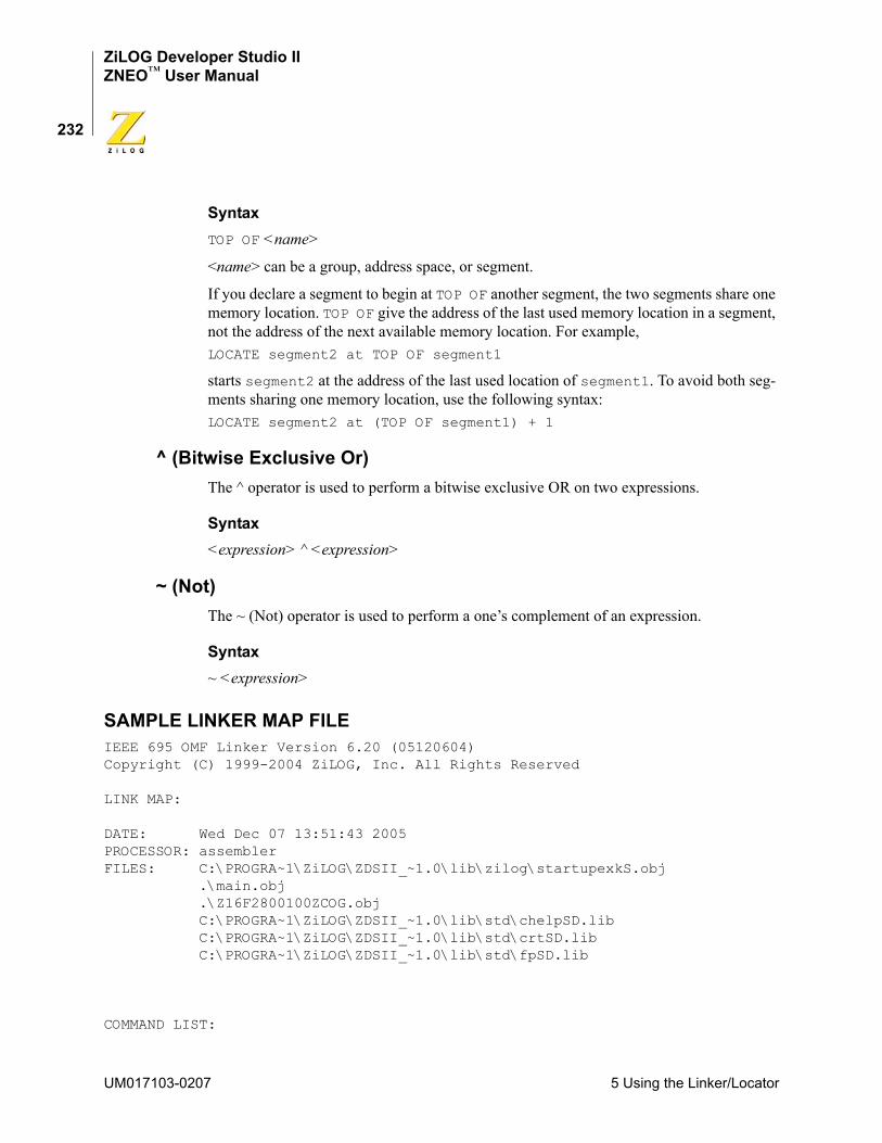
ZiLOG Developer Studio IIZNEO™ User Manual
232
SyntaxTOP OF <name>
<name> can be a group, address space, or segment.
If you declare a segment to begin at TOP OF another segment, the two segments share one memory location. TOP OF give the address of the last used memory location in a segment, not the address of the next available memory location. For example,LOCATE segment2 at TOP OF segment1
starts segment2 at the address of the last used location of segment1. To avoid both seg-ments sharing one memory location, use the following syntax: LOCATE segment2 at (TOP OF segment1) + 1
^ (Bitwise Exclusive Or)The ^ operator is used to perform a bitwise exclusive OR on two expressions.
Syntax<expression> ^ <expression>
~ (Not)The ~ (Not) operator is used to perform a one’s complement of an expression.
Syntax~ <expression>
SAMPLE LINKER MAP FILEIEEE 695 OMF Linker Version 6.20 (05120604)Copyright (C) 1999-2004 ZiLOG, Inc. All Rights Reserved
LINK MAP:
DATE: Wed Dec 07 13:51:43 2005PROCESSOR: assemblerFILES: C:\PROGRA~1\ZiLOG\ZDSII_~1.0\lib\zilog\startupexkS.obj .\main.obj .\Z16F2800100ZCOG.obj C:\PROGRA~1\ZiLOG\ZDSII_~1.0\lib\std\chelpSD.lib C:\PROGRA~1\ZiLOG\ZDSII_~1.0\lib\std\crtSD.lib C:\PROGRA~1\ZiLOG\ZDSII_~1.0\lib\std\fpSD.lib
COMMAND LIST:
UM017103-0207 5 Using the Linker/Locator
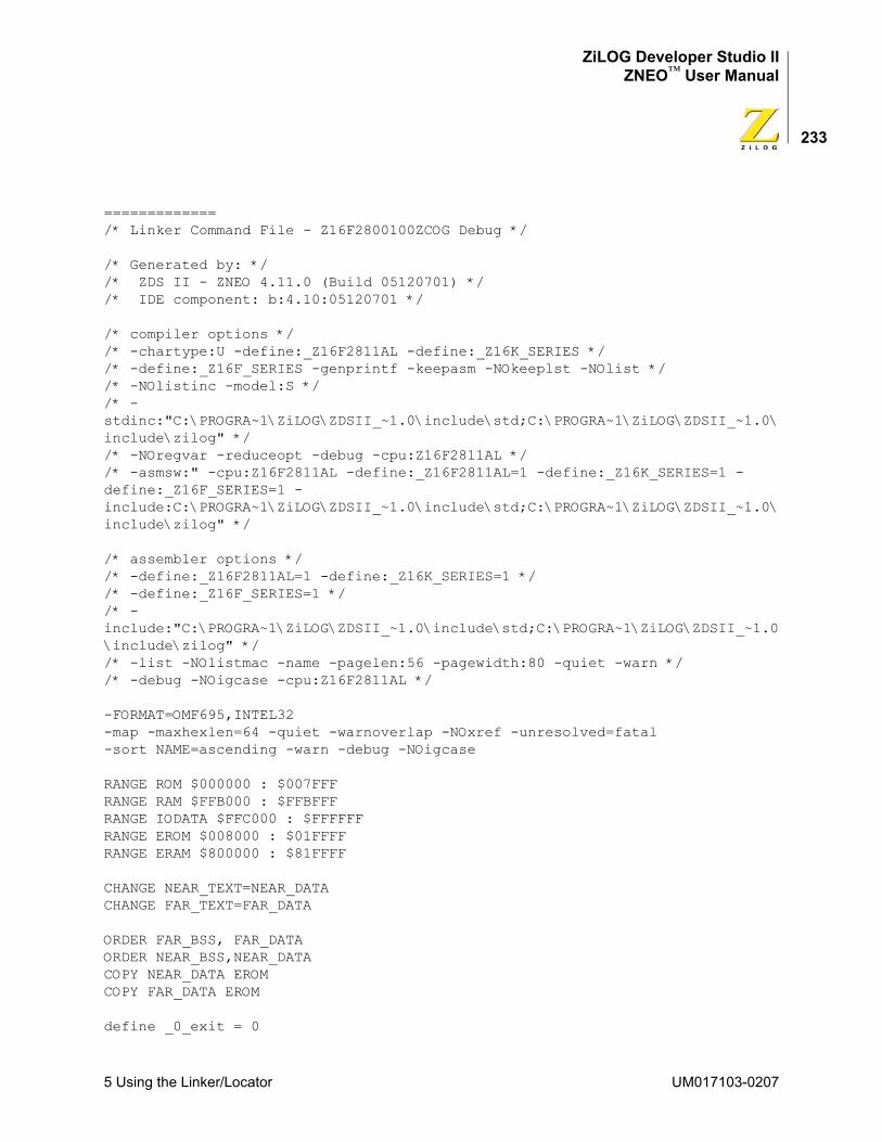
ZiLOG Developer Studio IIZNEO™ User Manual
233
=============/* Linker Command File - Z16F2800100ZCOG Debug */
/* Generated by: *//* ZDS II - ZNEO 4.11.0 (Build 05120701) *//* IDE component: b:4.10:05120701 */
/* compiler options *//* -chartype:U -define:_Z16F2811AL -define:_Z16K_SERIES *//* -define:_Z16F_SERIES -genprintf -keepasm -NOkeeplst -NOlist *//* -NOlistinc -model:S *//* -stdinc:"C:\PROGRA~1\ZiLOG\ZDSII_~1.0\include\std;C:\PROGRA~1\ZiLOG\ZDSII_~1.0\include\zilog" *//* -NOregvar -reduceopt -debug -cpu:Z16F2811AL *//* -asmsw:" -cpu:Z16F2811AL -define:_Z16F2811AL=1 -define:_Z16K_SERIES=1 -define:_Z16F_SERIES=1 -include:C:\PROGRA~1\ZiLOG\ZDSII_~1.0\include\std;C:\PROGRA~1\ZiLOG\ZDSII_~1.0\include\zilog" */
/* assembler options *//* -define:_Z16F2811AL=1 -define:_Z16K_SERIES=1 *//* -define:_Z16F_SERIES=1 *//* -include:"C:\PROGRA~1\ZiLOG\ZDSII_~1.0\include\std;C:\PROGRA~1\ZiLOG\ZDSII_~1.0\include\zilog" *//* -list -NOlistmac -name -pagelen:56 -pagewidth:80 -quiet -warn *//* -debug -NOigcase -cpu:Z16F2811AL */
-FORMAT=OMF695,INTEL32-map -maxhexlen=64 -quiet -warnoverlap -NOxref -unresolved=fatal-sort NAME=ascending -warn -debug -NOigcase
RANGE ROM $000000 : $007FFFRANGE RAM $FFB000 : $FFBFFFRANGE IODATA $FFC000 : $FFFFFFRANGE EROM $008000 : $01FFFFRANGE ERAM $800000 : $81FFFF
CHANGE NEAR_TEXT=NEAR_DATACHANGE FAR_TEXT=FAR_DATA
ORDER FAR_BSS, FAR_DATAORDER NEAR_BSS,NEAR_DATACOPY NEAR_DATA EROMCOPY FAR_DATA EROM
define _0_exit = 0
5 Using the Linker/Locator UM017103-0207
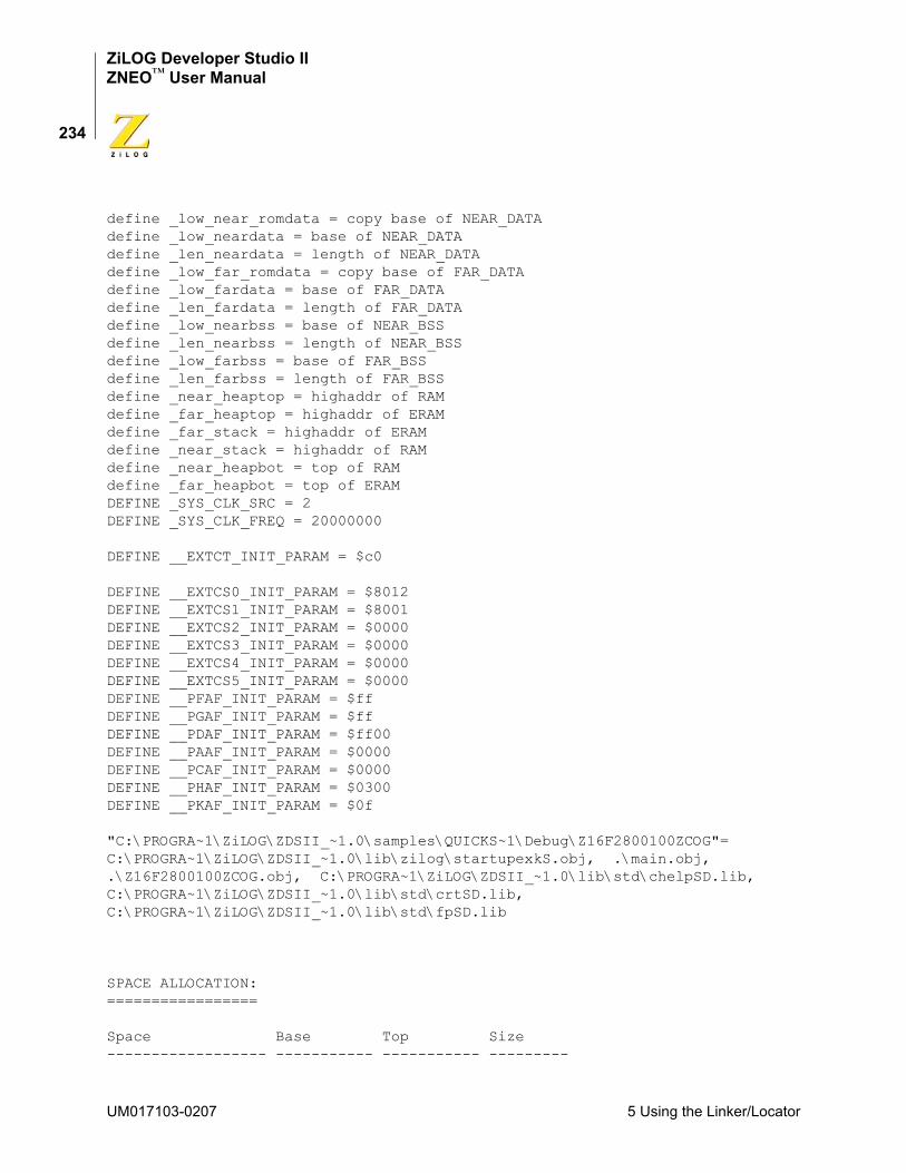
ZiLOG Developer Studio IIZNEO™ User Manual
234
define _low_near_romdata = copy base of NEAR_DATAdefine _low_neardata = base of NEAR_DATAdefine _len_neardata = length of NEAR_DATAdefine _low_far_romdata = copy base of FAR_DATAdefine _low_fardata = base of FAR_DATAdefine _len_fardata = length of FAR_DATAdefine _low_nearbss = base of NEAR_BSSdefine _len_nearbss = length of NEAR_BSSdefine _low_farbss = base of FAR_BSSdefine _len_farbss = length of FAR_BSSdefine _near_heaptop = highaddr of RAMdefine _far_heaptop = highaddr of ERAMdefine _far_stack = highaddr of ERAMdefine _near_stack = highaddr of RAMdefine _near_heapbot = top of RAMdefine _far_heapbot = top of ERAMDEFINE _SYS_CLK_SRC = 2DEFINE _SYS_CLK_FREQ = 20000000
DEFINE __EXTCT_INIT_PARAM = $c0
DEFINE __EXTCS0_INIT_PARAM = $8012DEFINE __EXTCS1_INIT_PARAM = $8001DEFINE __EXTCS2_INIT_PARAM = $0000DEFINE __EXTCS3_INIT_PARAM = $0000DEFINE __EXTCS4_INIT_PARAM = $0000DEFINE __EXTCS5_INIT_PARAM = $0000DEFINE __PFAF_INIT_PARAM = $ffDEFINE __PGAF_INIT_PARAM = $ffDEFINE __PDAF_INIT_PARAM = $ff00DEFINE __PAAF_INIT_PARAM = $0000DEFINE __PCAF_INIT_PARAM = $0000DEFINE __PHAF_INIT_PARAM = $0300DEFINE __PKAF_INIT_PARAM = $0f
"C:\PROGRA~1\ZiLOG\ZDSII_~1.0\samples\QUICKS~1\Debug\Z16F2800100ZCOG"= C:\PROGRA~1\ZiLOG\ZDSII_~1.0\lib\zilog\startupexkS.obj, .\main.obj, .\Z16F2800100ZCOG.obj, C:\PROGRA~1\ZiLOG\ZDSII_~1.0\lib\std\chelpSD.lib, C:\PROGRA~1\ZiLOG\ZDSII_~1.0\lib\std\crtSD.lib, C:\PROGRA~1\ZiLOG\ZDSII_~1.0\lib\std\fpSD.lib
SPACE ALLOCATION:=================
Space Base Top Size------------------ ----------- ----------- ---------
UM017103-0207 5 Using the Linker/Locator
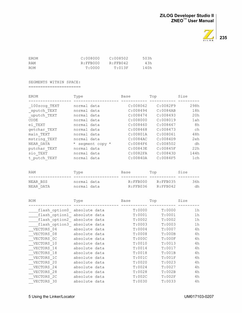
ZiLOG Developer Studio IIZNEO™ User Manual
235
EROM C:008000 C:008502 503hRAM R:FFB000 R:FFB042 43hROM T:0000 T:013F 140h
SEGMENTS WITHIN SPACE:======================
EROM Type Base Top Size------------------ ------------------- ----------- ----------- ---------_100zcog_TEXT normal data C:008062 C:0082F9 298h_sputch_TEXT normal data C:008494 C:0084AB 18h_uputch_TEXT normal data C:008474 C:008493 20hCODE normal data C:008000 C:008019 1ahei_TEXT normal data C:008460 C:008467 8hgetchar_TEXT normal data C:008468 C:008473 chmain_TEXT normal data C:00801A C:008061 48hmstring_TEXT normal data C:0084AC C:0084D9 2ehNEAR_DATA * segment copy * C:0084F6 C:008502 dhputchar_TEXT normal data C:00843E C:00845F 22hsio_TEXT normal data C:0082FA C:00843D 144ht_putch_TEXT normal data C:0084DA C:0084F5 1ch
RAM Type Base Top Size------------------ ------------------- ----------- ----------- ---------NEAR_BSS normal data R:FFB000 R:FFB035 36hNEAR_DATA normal data R:FFB036 R:FFB042 dh
ROM Type Base Top Size------------------ ------------------- ----------- ----------- ---------____flash_option0_ absolute data T:0000 T:0000 1h____flash_option1_ absolute data T:0001 T:0001 1h____flash_option2_ absolute data T:0002 T:0002 1h____flash_option3_ absolute data T:0003 T:0003 1h__VECTORS_04 absolute data T:0004 T:0007 4h__VECTORS_08 absolute data T:0008 T:000B 4h__VECTORS_0C absolute data T:000C T:000F 4h__VECTORS_10 absolute data T:0010 T:0013 4h__VECTORS_14 absolute data T:0014 T:0017 4h__VECTORS_18 absolute data T:0018 T:001B 4h__VECTORS_1C absolute data T:001C T:001F 4h__VECTORS_20 absolute data T:0020 T:0023 4h__VECTORS_24 absolute data T:0024 T:0027 4h__VECTORS_28 absolute data T:0028 T:002B 4h__VECTORS_2C absolute data T:002C T:002F 4h__VECTORS_30 absolute data T:0030 T:0033 4h
5 Using the Linker/Locator UM017103-0207
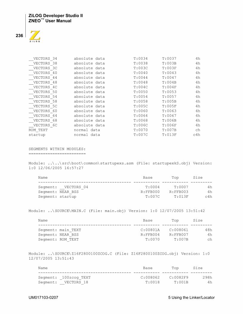
ZiLOG Developer Studio IIZNEO™ User Manual
236
__VECTORS_34 absolute data T:0034 T:0037 4h__VECTORS_38 absolute data T:0038 T:003B 4h__VECTORS_3C absolute data T:003C T:003F 4h__VECTORS_40 absolute data T:0040 T:0043 4h__VECTORS_44 absolute data T:0044 T:0047 4h__VECTORS_48 absolute data T:0048 T:004B 4h__VECTORS_4C absolute data T:004C T:004F 4h__VECTORS_50 absolute data T:0050 T:0053 4h__VECTORS_54 absolute data T:0054 T:0057 4h__VECTORS_58 absolute data T:0058 T:005B 4h__VECTORS_5C absolute data T:005C T:005F 4h__VECTORS_60 absolute data T:0060 T:0063 4h__VECTORS_64 absolute data T:0064 T:0067 4h__VECTORS_68 absolute data T:0068 T:006B 4h__VECTORS_6C absolute data T:006C T:006F 4hROM_TEXT normal data T:0070 T:007B chstartup normal data T:007C T:013F c4h
SEGMENTS WITHIN MODULES:========================
Module: ..\..\src\boot\common\startupexs.asm (File: startupexkS.obj) Version: 1:0 12/06/2005 16:57:27
Name Base Top Size --------------------------------------- ----------- ----------- --------- Segment: __VECTORS_04 T:0004 T:0007 4h Segment: NEAR_BSS R:FFB000 R:FFB003 4h Segment: startup T:007C T:013F c4h
Module: ..\SOURCE\MAIN.C (File: main.obj) Version: 1:0 12/07/2005 13:51:42
Name Base Top Size --------------------------------------- ----------- ----------- --------- Segment: main_TEXT C:00801A C:008061 48h Segment: NEAR_BSS R:FFB004 R:FFB007 4h Segment: ROM_TEXT T:0070 T:007B ch
Module: ..\SOURCE\Z16F2800100ZCOG.C (File: Z16F2800100ZCOG.obj) Version: 1:0 12/07/2005 13:51:43
Name Base Top Size --------------------------------------- ----------- ----------- --------- Segment: _100zcog_TEXT C:008062 C:0082F9 298h Segment: __VECTORS_18 T:0018 T:001B 4h
UM017103-0207 5 Using the Linker/Locator
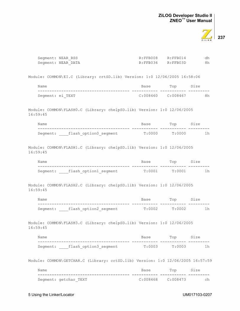
ZiLOG Developer Studio IIZNEO™ User Manual
237
Segment: NEAR_BSS R:FFB008 R:FFB014 dh Segment: NEAR_DATA R:FFB036 R:FFB03D 8h
Module: COMMON\EI.C (Library: crtSD.lib) Version: 1:0 12/06/2005 16:58:06
Name Base Top Size --------------------------------------- ----------- ----------- --------- Segment: ei_TEXT C:008460 C:008467 8h
Module: COMMON\FLASH0.C (Library: chelpSD.lib) Version: 1:0 12/06/2005 16:59:45
Name Base Top Size --------------------------------------- ----------- ----------- --------- Segment: ____flash_option0_segment T:0000 T:0000 1h
Module: COMMON\FLASH1.C (Library: chelpSD.lib) Version: 1:0 12/06/2005 16:59:45
Name Base Top Size --------------------------------------- ----------- ----------- --------- Segment: ____flash_option1_segment T:0001 T:0001 1h
Module: COMMON\FLASH2.C (Library: chelpSD.lib) Version: 1:0 12/06/2005 16:59:45
Name Base Top Size --------------------------------------- ----------- ----------- --------- Segment: ____flash_option2_segment T:0002 T:0002 1h
Module: COMMON\FLASH3.C (Library: chelpSD.lib) Version: 1:0 12/06/2005 16:59:45
Name Base Top Size --------------------------------------- ----------- ----------- --------- Segment: ____flash_option3_segment T:0003 T:0003 1h
Module: COMMON\GETCHAR.C (Library: crtSD.lib) Version: 1:0 12/06/2005 16:57:59
Name Base Top Size --------------------------------------- ----------- ----------- --------- Segment: getchar_TEXT C:008468 C:008473 ch
5 Using the Linker/Locator UM017103-0207
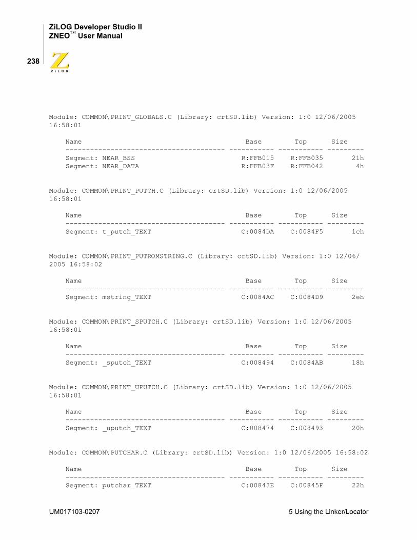
ZiLOG Developer Studio IIZNEO™ User Manual
238
Module: COMMON\PRINT_GLOBALS.C (Library: crtSD.lib) Version: 1:0 12/06/2005 16:58:01
Name Base Top Size --------------------------------------- ----------- ----------- --------- Segment: NEAR_BSS R:FFB015 R:FFB035 21h Segment: NEAR_DATA R:FFB03F R:FFB042 4h
Module: COMMON\PRINT_PUTCH.C (Library: crtSD.lib) Version: 1:0 12/06/2005 16:58:01
Name Base Top Size --------------------------------------- ----------- ----------- --------- Segment: t_putch_TEXT C:0084DA C:0084F5 1ch
Module: COMMON\PRINT_PUTROMSTRING.C (Library: crtSD.lib) Version: 1:0 12/06/2005 16:58:02
Name Base Top Size --------------------------------------- ----------- ----------- --------- Segment: mstring_TEXT C:0084AC C:0084D9 2eh
Module: COMMON\PRINT_SPUTCH.C (Library: crtSD.lib) Version: 1:0 12/06/2005 16:58:01
Name Base Top Size --------------------------------------- ----------- ----------- --------- Segment: _sputch_TEXT C:008494 C:0084AB 18h
Module: COMMON\PRINT_UPUTCH.C (Library: crtSD.lib) Version: 1:0 12/06/2005 16:58:01
Name Base Top Size --------------------------------------- ----------- ----------- --------- Segment: _uputch_TEXT C:008474 C:008493 20h
Module: COMMON\PUTCHAR.C (Library: crtSD.lib) Version: 1:0 12/06/2005 16:58:02
Name Base Top Size --------------------------------------- ----------- ----------- --------- Segment: putchar_TEXT C:00843E C:00845F 22h
UM017103-0207 5 Using the Linker/Locator
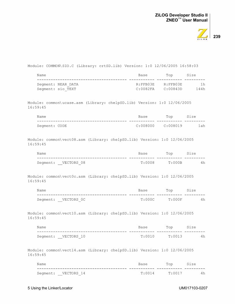
ZiLOG Developer Studio IIZNEO™ User Manual
239
Module: COMMON\SIO.C (Library: crtSD.lib) Version: 1:0 12/06/2005 16:58:03
Name Base Top Size --------------------------------------- ----------- ----------- --------- Segment: NEAR_DATA R:FFB03E R:FFB03E 1h Segment: sio_TEXT C:0082FA C:00843D 144h
Module: common\ucase.asm (Library: chelpSD.lib) Version: 1:0 12/06/2005 16:59:45
Name Base Top Size --------------------------------------- ----------- ----------- --------- Segment: CODE C:008000 C:008019 1ah
Module: common\vect08.asm (Library: chelpSD.lib) Version: 1:0 12/06/2005 16:59:45
Name Base Top Size --------------------------------------- ----------- ----------- --------- Segment: __VECTORS_08 T:0008 T:000B 4h
Module: common\vect0c.asm (Library: chelpSD.lib) Version: 1:0 12/06/2005 16:59:45
Name Base Top Size --------------------------------------- ----------- ----------- --------- Segment: __VECTORS_0C T:000C T:000F 4h
Module: common\vect10.asm (Library: chelpSD.lib) Version: 1:0 12/06/2005 16:59:45
Name Base Top Size --------------------------------------- ----------- ----------- --------- Segment: __VECTORS_10 T:0010 T:0013 4h
Module: common\vect14.asm (Library: chelpSD.lib) Version: 1:0 12/06/2005 16:59:45
Name Base Top Size --------------------------------------- ----------- ----------- --------- Segment: __VECTORS_14 T:0014 T:0017 4h
5 Using the Linker/Locator UM017103-0207
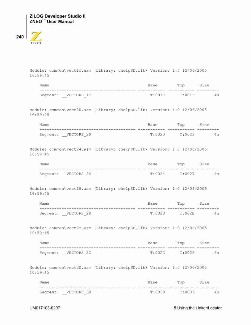
ZiLOG Developer Studio IIZNEO™ User Manual
240
Module: common\vect1c.asm (Library: chelpSD.lib) Version: 1:0 12/06/2005 16:59:45
Name Base Top Size --------------------------------------- ----------- ----------- --------- Segment: __VECTORS_1C T:001C T:001F 4h
Module: common\vect20.asm (Library: chelpSD.lib) Version: 1:0 12/06/2005 16:59:45
Name Base Top Size --------------------------------------- ----------- ----------- --------- Segment: __VECTORS_20 T:0020 T:0023 4h
Module: common\vect24.asm (Library: chelpSD.lib) Version: 1:0 12/06/2005 16:59:45
Name Base Top Size --------------------------------------- ----------- ----------- --------- Segment: __VECTORS_24 T:0024 T:0027 4h
Module: common\vect28.asm (Library: chelpSD.lib) Version: 1:0 12/06/2005 16:59:45
Name Base Top Size --------------------------------------- ----------- ----------- --------- Segment: __VECTORS_28 T:0028 T:002B 4h
Module: common\vect2c.asm (Library: chelpSD.lib) Version: 1:0 12/06/2005 16:59:45
Name Base Top Size --------------------------------------- ----------- ----------- --------- Segment: __VECTORS_2C T:002C T:002F 4h
Module: common\vect30.asm (Library: chelpSD.lib) Version: 1:0 12/06/2005 16:59:45
Name Base Top Size --------------------------------------- ----------- ----------- --------- Segment: __VECTORS_30 T:0030 T:0033 4h
UM017103-0207 5 Using the Linker/Locator
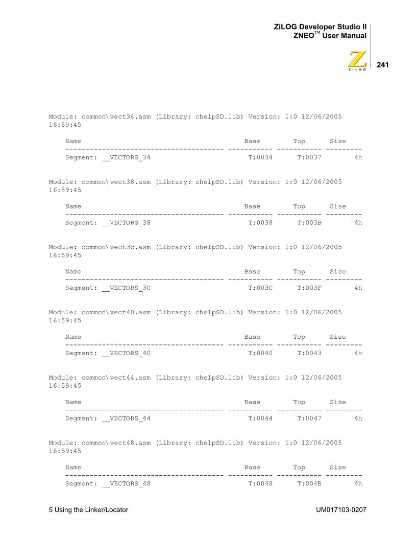
ZiLOG Developer Studio IIZNEO™ User Manual
241
Module: common\vect34.asm (Library: chelpSD.lib) Version: 1:0 12/06/2005 16:59:45
Name Base Top Size --------------------------------------- ----------- ----------- --------- Segment: __VECTORS_34 T:0034 T:0037 4h
Module: common\vect38.asm (Library: chelpSD.lib) Version: 1:0 12/06/2005 16:59:45
Name Base Top Size --------------------------------------- ----------- ----------- --------- Segment: __VECTORS_38 T:0038 T:003B 4h
Module: common\vect3c.asm (Library: chelpSD.lib) Version: 1:0 12/06/2005 16:59:45
Name Base Top Size --------------------------------------- ----------- ----------- --------- Segment: __VECTORS_3C T:003C T:003F 4h
Module: common\vect40.asm (Library: chelpSD.lib) Version: 1:0 12/06/2005 16:59:45
Name Base Top Size --------------------------------------- ----------- ----------- --------- Segment: __VECTORS_40 T:0040 T:0043 4h
Module: common\vect44.asm (Library: chelpSD.lib) Version: 1:0 12/06/2005 16:59:45
Name Base Top Size --------------------------------------- ----------- ----------- --------- Segment: __VECTORS_44 T:0044 T:0047 4h
Module: common\vect48.asm (Library: chelpSD.lib) Version: 1:0 12/06/2005 16:59:45
Name Base Top Size --------------------------------------- ----------- ----------- --------- Segment: __VECTORS_48 T:0048 T:004B 4h
5 Using the Linker/Locator UM017103-0207

ZiLOG Developer Studio IIZNEO™ User Manual
242
Module: common\vect4c.asm (Library: chelpSD.lib) Version: 1:0 12/06/2005 16:59:45
Name Base Top Size --------------------------------------- ----------- ----------- --------- Segment: __VECTORS_4C T:004C T:004F 4h
Module: common\vect50.asm (Library: chelpSD.lib) Version: 1:0 12/06/2005 16:59:45
Name Base Top Size --------------------------------------- ----------- ----------- --------- Segment: __VECTORS_50 T:0050 T:0053 4h
Module: common\vect54.asm (Library: chelpSD.lib) Version: 1:0 12/06/2005 16:59:45
Name Base Top Size --------------------------------------- ----------- ----------- --------- Segment: __VECTORS_54 T:0054 T:0057 4h
Module: common\vect58.asm (Library: chelpSD.lib) Version: 1:0 12/06/2005 16:59:45
Name Base Top Size --------------------------------------- ----------- ----------- --------- Segment: __VECTORS_58 T:0058 T:005B 4h
Module: common\vect5c.asm (Library: chelpSD.lib) Version: 1:0 12/06/2005 16:59:45
Name Base Top Size --------------------------------------- ----------- ----------- --------- Segment: __VECTORS_5C T:005C T:005F 4h
Module: common\vect60.asm (Library: chelpSD.lib) Version: 1:0 12/06/2005 16:59:45
Name Base Top Size --------------------------------------- ----------- ----------- --------- Segment: __VECTORS_60 T:0060 T:0063 4h
UM017103-0207 5 Using the Linker/Locator
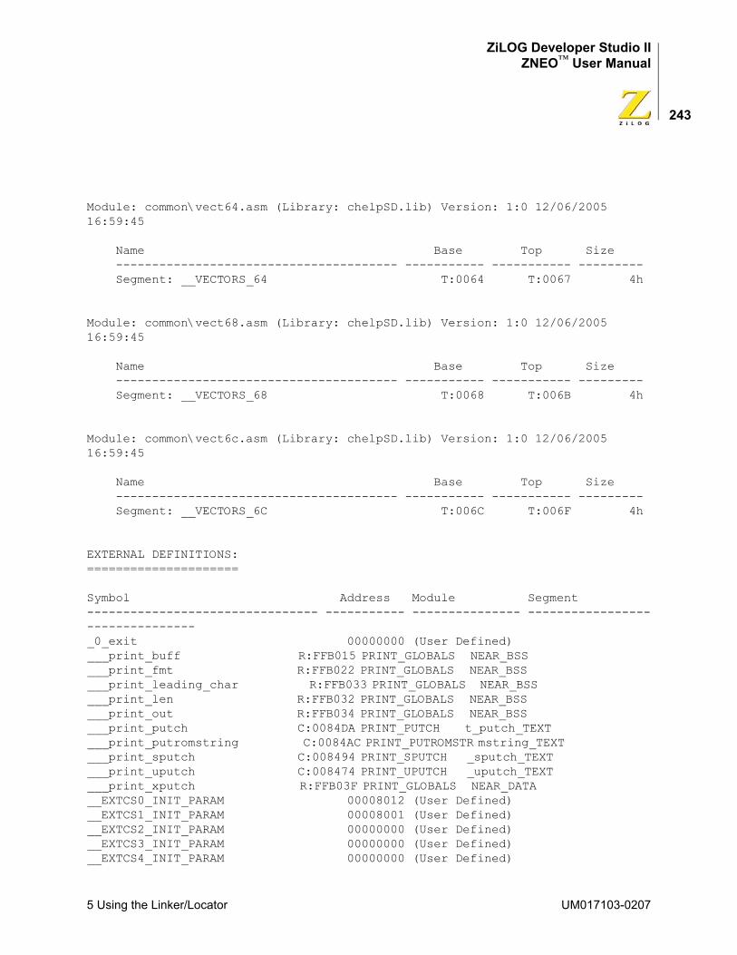
ZiLOG Developer Studio IIZNEO™ User Manual
243
Module: common\vect64.asm (Library: chelpSD.lib) Version: 1:0 12/06/2005 16:59:45
Name Base Top Size --------------------------------------- ----------- ----------- --------- Segment: __VECTORS_64 T:0064 T:0067 4h
Module: common\vect68.asm (Library: chelpSD.lib) Version: 1:0 12/06/2005 16:59:45
Name Base Top Size --------------------------------------- ----------- ----------- --------- Segment: __VECTORS_68 T:0068 T:006B 4h
Module: common\vect6c.asm (Library: chelpSD.lib) Version: 1:0 12/06/2005 16:59:45
Name Base Top Size --------------------------------------- ----------- ----------- --------- Segment: __VECTORS_6C T:006C T:006F 4h
EXTERNAL DEFINITIONS:=====================
Symbol Address Module Segment-------------------------------- ----------- --------------- --------------------------------_0_exit 00000000 (User Defined)___print_buff R:FFB015 PRINT_GLOBALS NEAR_BSS ___print_fmt R:FFB022 PRINT_GLOBALS NEAR_BSS ___print_leading_char R:FFB033 PRINT_GLOBALS NEAR_BSS ___print_len R:FFB032 PRINT_GLOBALS NEAR_BSS ___print_out R:FFB034 PRINT_GLOBALS NEAR_BSS ___print_putch C:0084DA PRINT_PUTCH t_putch_TEXT ___print_putromstring C:0084AC PRINT_PUTROMSTR mstring_TEXT ___print_sputch C:008494 PRINT_SPUTCH _sputch_TEXT ___print_uputch C:008474 PRINT_UPUTCH _uputch_TEXT ___print_xputch R:FFB03F PRINT_GLOBALS NEAR_DATA __EXTCS0_INIT_PARAM 00008012 (User Defined)__EXTCS1_INIT_PARAM 00008001 (User Defined)__EXTCS2_INIT_PARAM 00000000 (User Defined)__EXTCS3_INIT_PARAM 00000000 (User Defined)__EXTCS4_INIT_PARAM 00000000 (User Defined)
5 Using the Linker/Locator UM017103-0207
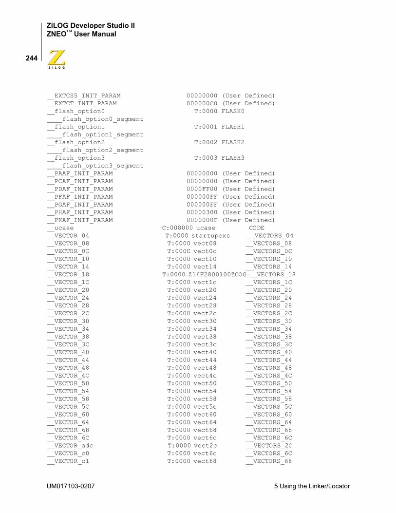
ZiLOG Developer Studio IIZNEO™ User Manual
244
__EXTCS5_INIT_PARAM 00000000 (User Defined)__EXTCT_INIT_PARAM 000000C0 (User Defined)__flash_option0 T:0000 FLASH0 ____flash_option0_segment __flash_option1 T:0001 FLASH1 ____flash_option1_segment __flash_option2 T:0002 FLASH2 ____flash_option2_segment __flash_option3 T:0003 FLASH3 ____flash_option3_segment __PAAF_INIT_PARAM 00000000 (User Defined)__PCAF_INIT_PARAM 00000000 (User Defined)__PDAF_INIT_PARAM 0000FF00 (User Defined)__PFAF_INIT_PARAM 000000FF (User Defined)__PGAF_INIT_PARAM 000000FF (User Defined)__PHAF_INIT_PARAM 00000300 (User Defined)__PKAF_INIT_PARAM 0000000F (User Defined)__ucase C:008000 ucase CODE __VECTOR_04 T:0000 startupexs __VECTORS_04 __VECTOR_08 T:0000 vect08 __VECTORS_08 __VECTOR_0C T:000C vect0c __VECTORS_0C __VECTOR_10 T:0000 vect10 __VECTORS_10 __VECTOR_14 T:0000 vect14 __VECTORS_14 __VECTOR_18 T:0000 Z16F2800100ZCOG __VECTORS_18 __VECTOR_1C T:0000 vect1c __VECTORS_1C __VECTOR_20 T:0000 vect20 __VECTORS_20 __VECTOR_24 T:0000 vect24 __VECTORS_24 __VECTOR_28 T:0000 vect28 __VECTORS_28 __VECTOR_2C T:0000 vect2c __VECTORS_2C __VECTOR_30 T:0000 vect30 __VECTORS_30 __VECTOR_34 T:0000 vect34 __VECTORS_34 __VECTOR_38 T:0000 vect38 __VECTORS_38 __VECTOR_3C T:0000 vect3c __VECTORS_3C __VECTOR_40 T:0000 vect40 __VECTORS_40 __VECTOR_44 T:0000 vect44 __VECTORS_44 __VECTOR_48 T:0000 vect48 __VECTORS_48 __VECTOR_4C T:0000 vect4c __VECTORS_4C __VECTOR_50 T:0000 vect50 __VECTORS_50 __VECTOR_54 T:0000 vect54 __VECTORS_54 __VECTOR_58 T:0000 vect58 __VECTORS_58 __VECTOR_5C T:0000 vect5c __VECTORS_5C __VECTOR_60 T:0000 vect60 __VECTORS_60 __VECTOR_64 T:0000 vect64 __VECTORS_64 __VECTOR_68 T:0000 vect68 __VECTORS_68 __VECTOR_6C T:0000 vect6c __VECTORS_6C __VECTOR_adc T:0000 vect2c __VECTORS_2C __VECTOR_c0 T:0000 vect6c __VECTORS_6C __VECTOR_c1 T:0000 vect68 __VECTORS_68
UM017103-0207 5 Using the Linker/Locator
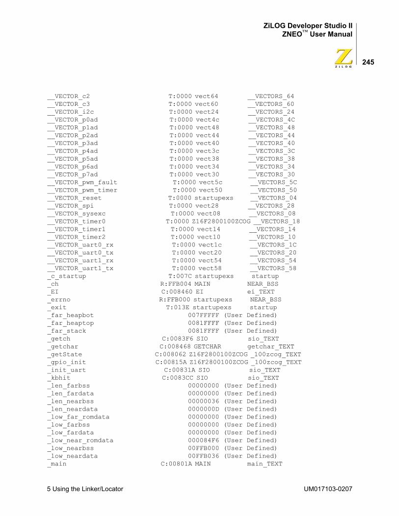
ZiLOG Developer Studio IIZNEO™ User Manual
245
__VECTOR_c2 T:0000 vect64 __VECTORS_64 __VECTOR_c3 T:0000 vect60 __VECTORS_60 __VECTOR_i2c T:0000 vect24 __VECTORS_24 __VECTOR_p0ad T:0000 vect4c __VECTORS_4C __VECTOR_p1ad T:0000 vect48 __VECTORS_48 __VECTOR_p2ad T:0000 vect44 __VECTORS_44 __VECTOR_p3ad T:0000 vect40 __VECTORS_40 __VECTOR_p4ad T:0000 vect3c __VECTORS_3C __VECTOR_p5ad T:0000 vect38 __VECTORS_38 __VECTOR_p6ad T:0000 vect34 __VECTORS_34 __VECTOR_p7ad T:0000 vect30 __VECTORS_30 __VECTOR_pwm_fault T:0000 vect5c __VECTORS_5C __VECTOR_pwm_timer T:0000 vect50 __VECTORS_50 __VECTOR_reset T:0000 startupexs __VECTORS_04 __VECTOR_spi T:0000 vect28 __VECTORS_28 __VECTOR_sysexc T:0000 vect08 __VECTORS_08 __VECTOR_timer0 T:0000 Z16F2800100ZCOG __VECTORS_18 __VECTOR_timer1 T:0000 vect14 __VECTORS_14 __VECTOR_timer2 T:0000 vect10 __VECTORS_10 __VECTOR_uart0_rx T:0000 vect1c __VECTORS_1C __VECTOR_uart0_tx T:0000 vect20 __VECTORS_20 __VECTOR_uart1_rx T:0000 vect54 __VECTORS_54 __VECTOR_uart1_tx T:0000 vect58 __VECTORS_58 _c_startup T:007C startupexs startup _ch R:FFB004 MAIN NEAR_BSS _EI C:008460 EI ei_TEXT _errno R:FFB000 startupexs NEAR_BSS _exit T:013E startupexs startup _far_heapbot 007FFFFF (User Defined)_far_heaptop 0081FFFF (User Defined)_far_stack 0081FFFF (User Defined)_getch C:0083F6 SIO sio_TEXT _getchar C:008468 GETCHAR getchar_TEXT _getState C:008062 Z16F2800100ZCOG _100zcog_TEXT _gpio_init C:00815A Z16F2800100ZCOG _100zcog_TEXT _init_uart C:00831A SIO sio_TEXT _kbhit C:0083CC SIO sio_TEXT _len_farbss 00000000 (User Defined)_len_fardata 00000000 (User Defined)_len_nearbss 00000036 (User Defined)_len_neardata 0000000D (User Defined)_low_far_romdata 00000000 (User Defined)_low_farbss 00000000 (User Defined)_low_fardata 00000000 (User Defined)_low_near_romdata 000084F6 (User Defined)_low_nearbss 00FFB000 (User Defined)_low_neardata 00FFB036 (User Defined)_main C:00801A MAIN main_TEXT
5 Using the Linker/Locator UM017103-0207
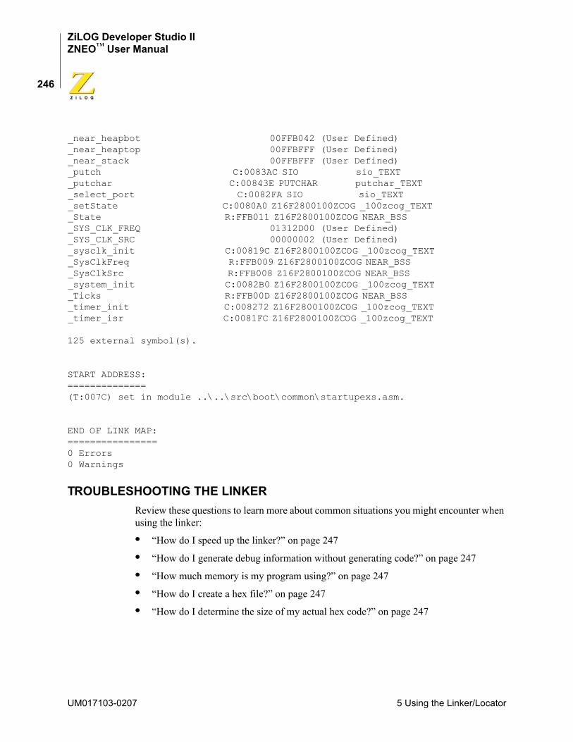
ZiLOG Developer Studio IIZNEO™ User Manual
246
_near_heapbot 00FFB042 (User Defined)_near_heaptop 00FFBFFF (User Defined)_near_stack 00FFBFFF (User Defined)_putch C:0083AC SIO sio_TEXT _putchar C:00843E PUTCHAR putchar_TEXT _select_port C:0082FA SIO sio_TEXT _setState C:0080A0 Z16F2800100ZCOG _100zcog_TEXT _State R:FFB011 Z16F2800100ZCOG NEAR_BSS _SYS_CLK_FREQ 01312D00 (User Defined)_SYS_CLK_SRC 00000002 (User Defined)_sysclk_init C:00819C Z16F2800100ZCOG _100zcog_TEXT _SysClkFreq R:FFB009 Z16F2800100ZCOG NEAR_BSS _SysClkSrc R:FFB008 Z16F2800100ZCOG NEAR_BSS _system_init C:0082B0 Z16F2800100ZCOG _100zcog_TEXT _Ticks R:FFB00D Z16F2800100ZCOG NEAR_BSS _timer_init C:008272 Z16F2800100ZCOG _100zcog_TEXT _timer_isr C:0081FC Z16F2800100ZCOG _100zcog_TEXT
125 external symbol(s).
START ADDRESS:==============(T:007C) set in module ..\..\src\boot\common\startupexs.asm.
END OF LINK MAP:================0 Errors0 Warnings
TROUBLESHOOTING THE LINKERReview these questions to learn more about common situations you might encounter when using the linker:
• “How do I speed up the linker?” on page 247
• “How do I generate debug information without generating code?” on page 247
• “How much memory is my program using?” on page 247
• “How do I create a hex file?” on page 247
• “How do I determine the size of my actual hex code?” on page 247
UM017103-0207 5 Using the Linker/Locator

ZiLOG Developer Studio IIZNEO™ User Manual
247
How do I speed up the linker?Use the following tips to lower linker execution times:
• If you do not need a link map file, deselect the Generate Map File check box in the Project Settings dialog box (Output page). See page 79.
• Make sure that all DOS windows are minimized.
How do I generate debug information without generating code?Use the COPY or CHANGE command in the linker to copy or change a segment to the predefined NULL space. If you copy the segment to the NULL space, the region is still allocated but no data is written for it. If you change the segment to the NULL space, the region is not allocated at all.
The following examples are of commands in the linker command file:COPY myseg NULLCHANGE myseg = NULL
How much memory is my program using?Unless the Generate Map File check box is unchecked in the Project Settings dialog box (Output page), the linker creates a link map file each time it is run. The link map file name is the same as your executable file with the .map extension and resides in the same direc-tory as your project file. The link map has a wealth of information about the memory requirements of your program. Views of memory usage from the space, segment, and module perspective are given as are the names and locations of all public symbols. See “Generate Map File” on page 79 and “MAP” on page 220.
How do I create a hex file?Select Intel Hex32 Records from the Executable Formats area in the Project Settings dia-log box (“Project Settings—Output Page” on page 78).
How do I determine the size of my actual hex code?Refer to the map file. Unless the Generate Map File check box is unchecked in the Project Settings dialog box (“Generate Map File” on page 79), the linker creates a link map file each time it is run. The link map file name is the same as your executable file with the .map extension and resides in the same directory as your project file.
5 Using the Linker/Locator UM017103-0207
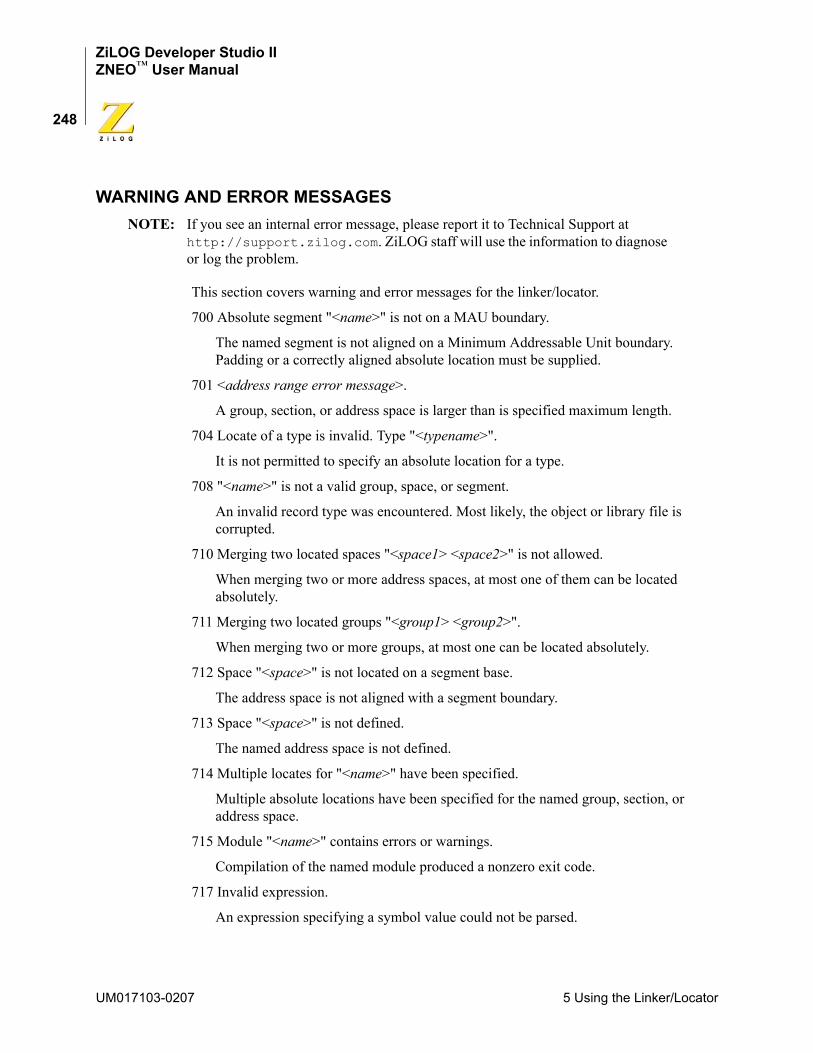
ZiLOG Developer Studio IIZNEO™ User Manual
248
WARNING AND ERROR MESSAGESNOTE: If you see an internal error message, please report it to Technical Support at
http://support.zilog.com. ZiLOG staff will use the information to diagnose or log the problem.
This section covers warning and error messages for the linker/locator.
700 Absolute segment "<name>" is not on a MAU boundary.
The named segment is not aligned on a Minimum Addressable Unit boundary. Padding or a correctly aligned absolute location must be supplied.
701 <address range error message>.
A group, section, or address space is larger than is specified maximum length.
704 Locate of a type is invalid. Type "<typename>".
It is not permitted to specify an absolute location for a type.
708 "<name>" is not a valid group, space, or segment.
An invalid record type was encountered. Most likely, the object or library file is corrupted.
710 Merging two located spaces "<space1> <space2>" is not allowed.
When merging two or more address spaces, at most one of them can be located absolutely.
711 Merging two located groups "<group1> <group2>".
When merging two or more groups, at most one can be located absolutely.
712 Space "<space>" is not located on a segment base.
The address space is not aligned with a segment boundary.
713 Space "<space>" is not defined.
The named address space is not defined.
714 Multiple locates for "<name>" have been specified.
Multiple absolute locations have been specified for the named group, section, or address space.
715 Module "<name>" contains errors or warnings.
Compilation of the named module produced a nonzero exit code.
717 Invalid expression.
An expression specifying a symbol value could not be parsed.
UM017103-0207 5 Using the Linker/Locator
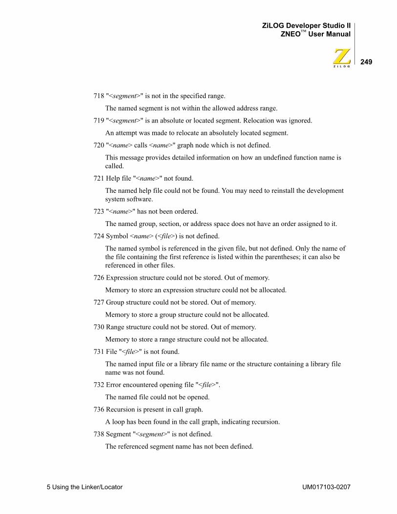
ZiLOG Developer Studio IIZNEO™ User Manual
249
718 "<segment>" is not in the specified range.
The named segment is not within the allowed address range.
719 "<segment>" is an absolute or located segment. Relocation was ignored.
An attempt was made to relocate an absolutely located segment.
720 "<name> calls <name>" graph node which is not defined.
This message provides detailed information on how an undefined function name is called.
721 Help file "<name>" not found.
The named help file could not be found. You may need to reinstall the development system software.
723 "<name>" has not been ordered.
The named group, section, or address space does not have an order assigned to it.
724 Symbol <name> (<file>) is not defined.
The named symbol is referenced in the given file, but not defined. Only the name of the file containing the first reference is listed within the parentheses; it can also be referenced in other files.
726 Expression structure could not be stored. Out of memory.
Memory to store an expression structure could not be allocated.
727 Group structure could not be stored. Out of memory.
Memory to store a group structure could not be allocated.
730 Range structure could not be stored. Out of memory.
Memory to store a range structure could not be allocated.
731 File "<file>" is not found.
The named input file or a library file name or the structure containing a library file name was not found.
732 Error encountered opening file "<file>".
The named file could not be opened.
736 Recursion is present in call graph.
A loop has been found in the call graph, indicating recursion.
738 Segment "<segment>" is not defined.
The referenced segment name has not been defined.
5 Using the Linker/Locator UM017103-0207
ZiLOG Developer Studio IIZNEO™ User Manual
250
739 Invalid space "<space>" is defined.
The named address space is not valid. It must be either a group or an address space.
740 Space "<space>" is not defined.
The referenced space name is not defined.
742 <error message>
A general-purpose error message.
743 Vector "<vector>" not defined.
The named interrupt vector could not be found in the symbol table.
745 Configuration bits mismatch in file <file>.
The mode bit in the current input file differs from previous input files.
746 Symbol <name> not attached to a valid segment.
The named symbol is not assigned to a valid segment.
747 <message>
General-purpose error message for reporting out-of-range errors. An address does not fit within the valid range.
748 <message>
General-purpose error message for OMF695 to OMF251 conversion. The requested translation could not proceed.
749 Could not allocate global register.
A global register was requested, but no register of the desired size remains available.
751 Error opening output file "<outfile>".
The named load module file could not be opened.
753 Segment '<segment>' being copied is splittable
A segment, which is to be copied, is being marked as splittable, but startup code might assume that it is contiguous.
UM017103-0207 5 Using the Linker/Locator
ZiLOG Developer Studio IIZNEO™ User Manual
251
6 Configuring Memory for Your ProgramThe ZNEO CPU architecture provides a single unified address space for both internal and external memory and I/O. Several address ranges within this space can be configured for various purposes, providing a great deal of flexibility for creating a program configuration tailored to your target design and application needs. The cost of this flexibility is that you need to understand how to set up the project settings and initialization to support your pre-ferred configuration. This chapter gives you the information needed to configure your project to support the programming model that best fits your needs.
This chapter covers the following topics:
• “ZNEO Memory Layout” on page 251
• “Programmer’s Model of ZNEO Memory” on page 253
• “Program Configurations” on page 258
The first two sections describe the relationship between the ZNEO CPU’s physical mem-ory layout and the functional address ranges available to the programmer. Understanding this relationship is the key to correctly configuring your project. The last section presents several examples of program configuration, covering the configurations that are expected to be most commonly used.
ZNEO MEMORY LAYOUTThe ZNEO CPU has a unique memory architecture with a unified 24-bit physical address space. (ZNEO CPU effective addresses are 32 bits wide, but current devices ignore bits [31:24].) The physical address space can address four types of memory and I/O, as fol-lows:
• Internal nonvolatile memory
• Internal RAM
• Internal I/O memory and special-function registers (SFRs)
• External memory and memory mapped peripherals.
The internal memory and I/O are always present in ZNEO devices, and are located at spe-cific address ranges in the unified address space. External memory or I/O is optional, and its location in the address space is determined by the target hardware design.
To promote code efficiency, the ZNEO CPU supports shorter 16-bit data addressing for the address ranges 00_0000H-00_7FFFH and FF_8000H-FF_FFFFH. 32-bit addressing can also be used in these ranges. The range 00_8000H–FF_7FFFH requires 32-bit addresses. Figure 87 on page 252 shows the typical address layout of memory types avail-able in the ZNEO architecture.
6 Configuring Memory for Your Program UM017103-0207
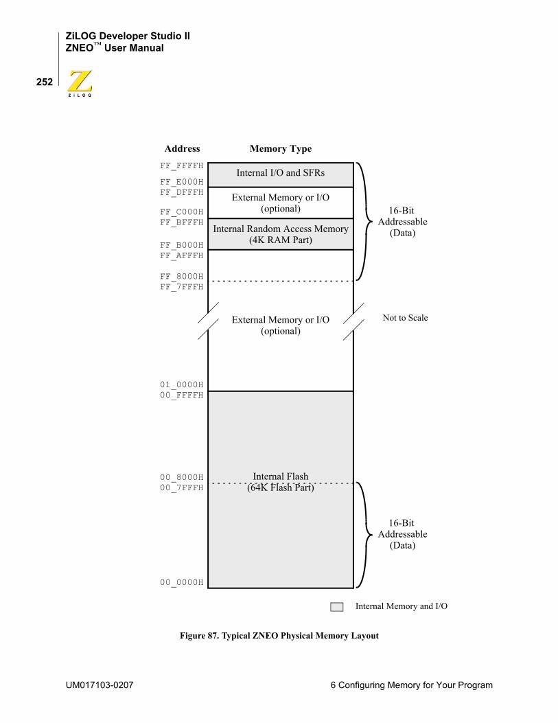
ZiLOG Developer Studio IIZNEO™ User Manual
252
Figure 87. Typical ZNEO Physical Memory Layout
Memory TypeAddressFF_FFFFH
FF_E000HFF_DFFFH
FF_C000HFF_BFFFH
FF_B000H
00_8000H00_7FFFH
00_0000H
Internal I/O and SFRs
External Memory or I/O(optional)
Internal Random Access Memory
External Memory or I/O(optional)
Internal Flash
(4K RAM Part)FF_AFFFH
FF_7FFFHFF_8000H
00_FFFFH01_0000H
(64K Flash Part)
16-Bit Addressable
16-Bit Addressable
Internal Memory and I/O
Not to Scale
(Data)
(Data)
UM017103-0207 6 Configuring Memory for Your Program
ZiLOG Developer Studio IIZNEO™ User Manual
253
ZNEO CPU-based devices have internal nonvolatile memory starting at address 00_0000H. For example, a device equipped with 128K of Flash has internal nonvolatile memory starting at address 00_0000H and ending at address 01_FFFFH.
ZNEO CPU-based devices have internal RAM ending at address FF_BFFFH, while the beginning address (and hence the total extent of this area) is device dependent. For exam-ple, a device equipped with 4K of RAM has internal RAM starting at address FF_B000H and ending at address FF_BFFFH.
ZNEO CPU-based devices reserve 8K of addresses for internal memory-mapped I/O, located at addresses FF_E000H-FF_FFFFH. This memory contains CPU control registers and other SFRs, on-chip peripherals, and memory-mapped I/O ports.
Finally, ZNEO CPU-based devices provide an external interface that allows seamless con-nection to external memory and/or peripherals. External memory can be nonvolatile mem-ory such as Flash, volatile (random access) memory, or both.
The external interface supports multiple chip select signals (CSx), which the target system designer can use as needed to enable different devices on the external interface. One chip select is asserted whenever an external memory or I/O address is accessed. Each chip select is available for use in a particular address range with a particular priority, but note that the actual external address ranges available on a target system depend on its design. For details about chip select priorities and address spaces, refer to the individual product specification for your ZNEO CPU-based device.
To use ZDS II, a detailed understanding of chip selects is not needed. It is only necessary to enable and configure the chip selects used by the target system, and to add the actual external address ranges, as implemented on the target, to the Address Spaces page of the Project Settings dialog box (see page 74).
PROGRAMMER’S MODEL OF ZNEO MEMORYDifferent address ranges in the 24-bit ZNEO CPU memory space are suited for different functions, depending on whether the corresponding memory is volatile or nonvolatile, whether it can be addressed using 16 or 32 bits, and whether it is reserved or otherwise convenient for I/O. The following considerations affect the suitability of an address range for various memory functions:
• Volatile (random access) memory contents can be changed easily, so it is used for storing variable data, and can also contain program code downloaded temporarily or copied from nonvolatile memory.
• Nonvolatile memory is not easily changed, but is also unaffected by power loss, so it is used for storing constants, variable initializers, program code, option bits, and vectors.
• Data in 16-bit addressable memory can be addressed with short pointers and instructions, so using these spaces for data results in more compact code. However, 16
6 Configuring Memory for Your Program UM017103-0207
ZiLOG Developer Studio IIZNEO™ User Manual
254
bit addresses can access only two 32KB areas, one in low memory and one in high memory, so data-intensive applications might also need to use some 32-bit addressed memory for data.
• Program code is always fetched using the 32-bit program counter, so there are no addressing restrictions for program code. Placing as little program code as possible in the 16-bit addressable (for data) space leaves more memory available in that space for data.
• The ZNEO microcontroller I/O and special function registers are located in the highest 8KB of its 24-bit address space, and extra chip selects are available for external I/O in the space immediately below internal I/O. Locating I/O functions in the high-memory 16-bit addressable space allows efficient access to I/O devices.
ZDS II uses five configurable memory ranges to associate a functional purpose to each part of the target system’s physical memory map. You can configure the address ranges for each function in the Linker page of the Project Settings dialog box (see “Project Set-tings—Address Spaces Page” on page 74). Each address range has a corresponding mne-monic that is used with the assembly language SPACE keyword. The five address ranges and their SPACE mnemonics are:
• Constant data (ROM)—This range is typically 00_0000H-00_1FFFH for devices with 32 KB of internal Flash, 00_0000H-00_3FFFH for devices with 64 KB of internal Flash, and 00_0000H-00_7FFFH for devices with 128 KB of internal Flash. The lower boundary must be 00_0000H. The upper boundary can be lower than 00_7FFFH, but no higher. Data in this range is addressable using 16 or 32 bits.
The ROM address range includes the ZNEO CPU option bytes and vector table. The C-Compiler uses the ROM range for constant data, data tables, and startup code. The assembly language programmer can place any executable code in the ROM range if desired.
The ROM range typically includes only internal Flash, but can include external nonvolatile memory if, for example, internal Flash is disabled.
NOTE: To use any external memory provided on the target system, you must configure the memory’s chip select in the Configure Target dialog box. See “Project Settings—Debugger Page” on page 81.
• Program space (EROM)—Identifies any 32-bit addressed nonvolatile memory space outside the ROM range. This range is typically 00_2000H-00_7FFFH for devices with 32 KB of internal Flash, 00_4000H-00_FFFFH for devices with 64 KB of internal Flash, and 00_8000H-01_FFFFH for devices with 128 KB of internal Flash. Specify a larger range only if the target system provides external nonvolatile memory.
UM017103-0207 6 Configuring Memory for Your Program
ZiLOG Developer Studio IIZNEO™ User Manual
255
The EROM range extends to the highest nonvolatile memory address in the target system. ZDS II requires the highest EROM address to fall below the specified ERAM (if present) and RAM ranges.
Normally, the EROM range begins immediately above the ROM range, but this is not required. The EROM range can include both internal Flash and external nonvolatile memory, if present. The EROM range is the primary location for storing executable code in most applications.
• Extended RAM (ERAM)—The ERAM address range identifies any 32-bit addressed random access memory on the target. In current ZNEO CPU-based devices, ERAM is always external memory. The ERAM range must begin above the highest EROM address. Also, the ZDS II GUI does not allow an ERAM starting address below 80_0000H. An address gap is allowed between the EROM and ERAM ranges. The C-Compiler does not support gaps (holes) within the ERAM range.
The highest ERAM address must fall below the specified RAM address range. (Any external volatile memory that is present at or above FF_8000H is 16-bit addressable, so it should be assigned to the RAM range.) The ERAM address range can be used for data, stack, or executable code. For details, see “Program Configurations” on page 258.
• Internal RAM (RAM)—Typically FF_B700H-FF_BFFFH for 2KB internal RAM or FF_B000H-FF_BFFFH for 4KB internal RAM. Despite its name, this range can be expanded up to FF_8000H-FF_BFFFH if the target system provides external random access memory to fill out this address range. This GUI field does not allow a high RAM address boundary above FF_BFFFH.
The RAM address range is addressable using either 16 or 32 bits (the ZNEO CPU sign-extends 16-bit addresses). The C-Compiler does not support gaps (holes) within the RAM range.
ZDS II uses the RAM address range for nonpermanent storage of data during program execution. ZDS II can be configured to place code in the RAM address range, if desired. For more information, see “Program Configurations” on page 258.
• Special Function Registers and IO (IODATA)—Typically FF_C000H-FF_FFFFH. The microcontroller reserves addresses FF_E000H and above for its special function registers, on-chip peripherals, and I/O ports. The ZDS II GUI expects addresses FF_C000H to FF_DFFFH to be used for external I/O (if any) on the target system.
The IODATA address range is addressable using 16 or 32 bits (the ZNEO CPU sign-extends 16-bit addresses). ZDS II does not support placing executable code in the IODATA space.
Figure 88 on page 256 illustrates typical contents of the five ZDS II address ranges and an example of how they might map to a target’s physical memory.
6 Configuring Memory for Your Program UM017103-0207
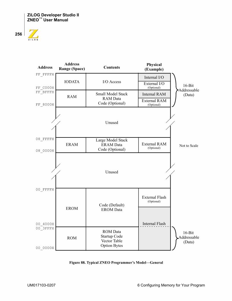
ZiLOG Developer Studio IIZNEO™ User Manual
256
Figure 88. Typical ZNEO Programmer’s Model—General
PhysicalAddressFF_FFFFH
FF_C000HFF_BFFFH
00_4000H00_3FFFH
00_0000H
Internal I/O
Internal RAM
External RAM
Internal Flash
16-Bit Addressable
16-Bit Addressable
Not to Scale
Address
IODATA
ERAM
ROM
RAMExternal RAM
EROM
External I/O
08_0000H
08_FFFFH
FF_8000H
I/O Access
00_FFFFH
Small Model StackRAM Data
Code (Optional)
Large Model StackERAM Data
Code (Optional)
Code (Default)EROM Data
ROM DataStartup CodeVector TableOption Bytes
Unused
Unused
Contents (Example)
External Flash
(Optional)
(Optional)
(Optional)
(Optional)
Range (Space)
(Data)
(Data)
UM017103-0207 6 Configuring Memory for Your Program
ZiLOG Developer Studio IIZNEO™ User Manual
257
The following default segments are provided by the assembler and associated with spe-cific address spaces as shown in the following table:
For a detailed description of these segments, see “Predefined Segments” on page 168.
You can define your own segments in these address spaces using the DEFINE assembler directive. For example:DEFINE romseg, SPACE=ROM ; Defines the new segment romsegSEGMENT romseg ; Sets the current segment to romseg
See “User-Defined Segments” on page 169 for further details.
Unconventional Memory LayoutsIt might be necessary for a target design to locate memory or I/O in an address range that the ZDS II GUI does not directly accommodate. Some GUI address range limitations can be circumvented, as follows:
• The GUI rejects an ERAM range lower boundary setting below 80_0000H. If the target locates external volatile memory below this address, an unrestricted ERAM range can be configured by adding an edited linker RANGE command to the “Additional Linker Commands” field of the ZDS II project settings. For example, if the target provides 8MB of extended RAM at address 70_0000H, you would use this command: RANGE ERAM $700000 : $FEFFFF
• The GUI rejects a RAM range upper boundary setting above FF_BFFFH. If the target uses the space above this address for external volatile memory instead of external I/O, a higher RAM upper boundary (up to FF_DFFFH) can be configured by adding an edited linker RANGE command to the “Additional Linker Commands” field of the ZDS II project settings. The debugger memory window always displays addresses above FF_BFFFH as part of the I/O Data space, however. For example, if the target provides 24KB of combined internal and external RAM beginning at FF_8000H, you would use this command:RANGE RAM $FF8000 : $FFDFFF
Address Range (Space) SegmentROM ROM_DATA, ROM_TEXT, __VECTORSEROM CODE, EROM_DATA, EROM_TEXTRAM NEAR_DATA, NEAR_BSS, NEAR_TEXTERAM FAR_DATA, FAR_BSS, FAR_TEXTIODATA IOSEG
6 Configuring Memory for Your Program UM017103-0207
ZiLOG Developer Studio IIZNEO™ User Manual
258
• The ZDS II GUI assumes external I/O is located in the range FF_C000H to FF_DFFFH. Any external I/O that is located elsewhere can be accessed using absolute addresses. The debugger memory window displays all addresses below FF_C000H as part of the Memory space, however.
PROGRAM CONFIGURATIONSWith the information given so far in this chapter as background, you are now ready to plan the memory configuration for your own application. At this point, you should have deter-mined what external memory, if any, is present on your target system, enabled and config-ured its chip selects, and added its address space to the linker address ranges. For information about these settings, see “Project Settings—Debugger Page” on page 81 and “Project Settings—Address Spaces Page” on page 74.
Now it is necessary to implement your program’s memory configuration using the devel-opment environment and tools. This section presents several examples of this process, beginning with the default program configuration provided by the ZiLOG development tools. For each configuration, there is a discussion of reasons to choose the configuration and how to implement the configuration in both C and assembly language projects.
Two distinct features of a program configuration are how its code is downloaded and how its initial values are copied. Downloading refers to what the development tools do when they copy your compiled or assembled code and data from your host computer to the ZNEO CPU’s internal or external memory in preparation for a debugging or test session. The memory space (ZDS II address range) or spaces into which your program is down-loaded depend on the memory model that best fits your application. You might also choose to change those spaces as your application evolves from the early stages of development closer to production.
The copying of initial values, on the other hand, is carried out by the startup code in your application. Usually, the startup code copies values from nonvolatile memory to a location in volatile memory where they are accessed in the main body of your program. In addition to copying data that must have a specific value on program startup, the startup code can also set otherwise uninitialized values to zero (to conform with the C standard). Unlike the downloading step, the copying step continues to occur in your production code, typically when the end-user device is powered up or reset.
Default Program ConfigurationThe default program configuration (Figure 89) provided by ZNEO development tools can be used for production code as well as development. It is designed to provide a general case that meets the needs of many users. In this configuration, your compiled or assembled program is all downloaded to the ROM or EROM functional address spaces.
The startup code (which is provided in the form of both source code and the standard, pre-compiled C startup module) is downloaded to ROM, and the rest of the executable pro-gram code is downloaded to EROM. The ROM/EROM data (declared using the _Rom or
UM017103-0207 6 Configuring Memory for Your Program
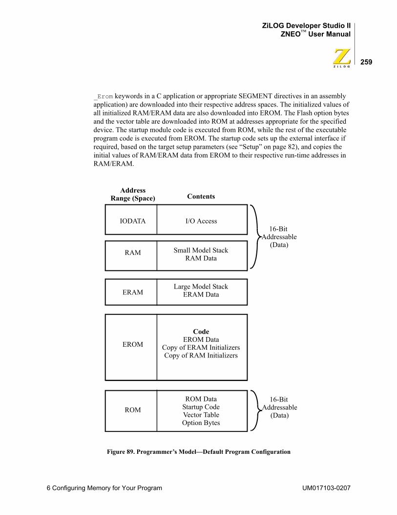
ZiLOG Developer Studio IIZNEO™ User Manual
259
_Erom keywords in a C application or appropriate SEGMENT directives in an assembly application) are downloaded into their respective address spaces. The initialized values of all initialized RAM/ERAM data are also downloaded into EROM. The Flash option bytes and the vector table are downloaded into ROM at addresses appropriate for the specified device. The startup module code is executed from ROM, while the rest of the executable program code is executed from EROM. The startup code sets up the external interface if required, based on the target setup parameters (see “Setup” on page 82), and copies the initial values of RAM/ERAM data from EROM to their respective run-time addresses in RAM/ERAM.
Figure 89. Programmer’s Model—Default Program Configuration
CodeEROM Data
Copy of ERAM InitializersCopy of RAM Initializers
16-Bit Addressable
16-Bit Addressable
Address
IODATA
ERAM
ROM
RAM
EROM
I/O Access
Small Model StackRAM Data
Large Model StackERAM Data
ROM DataStartup CodeVector TableOption Bytes
ContentsRange (Space)
(Data)
(Data)
6 Configuring Memory for Your Program UM017103-0207
ZiLOG Developer Studio IIZNEO™ User Manual
260
NOTE: Figure 89 and the other program configuration figures omit physical address and interface information to emphasize that, once the address ranges have been defined in the project setup, most memory locations can be expressed symbolically in terms of the functional space (address range) in which they are located.
C Program SetupThis is the default setup provided by the development tools. You do not have to perform any additional steps to achieve this configuration. A point to note is that if the C program is a large model program, the data and stack reside in ERAM by default, so selecting the large model is not appropriate unless the target has external random access memory that you have configured in the target setup and added to the ERAM linker address range.
Assembly Program SetupAs an assembly user, you can choose either to use the default segments or to define and use your own segments in various address spaces. To avoid problems, you need to observe the following guidelines to achieve the same configuration as that used in the default C program configuration:
• Locate the reset vector routine in the internal memory portion of ROM. For example: vector reset = _startup
define ROMSEG, space=ROM, org=%70 segment ROMSEG_startup: ; startup code here; any external memory interface initialization should be done here; any RAM/ERAM data copying should be done here
• Locate the rest of the executable program in EROM. For example:segment CODE; program code goes here
• Locate the initialized constant data in ROM/EROM.
• Only allocate space for data in RAM/ERAM using the DS assembler directive and make sure to not perform any initializations using the DB/DW/DL directive for such data. Any initializations of RAM/ERAM data should be done in your code. For example:
segment NEAR_BSSval: DS 4 ; allocate 4 uninitialized bytes: OK
segment codeld r0, #%12345678ld val, r0 ; initialize ram location val as part of code: OK
segment NEAR_BSS val: dl %12345678 ; incorrect usage for production code, as RAM does
; not retain value across power cycles: NOT OK
UM017103-0207 6 Configuring Memory for Your Program
ZiLOG Developer Studio IIZNEO™ User Manual
261
If your application has a lot of such initializations, this approach can be tedious. In that case, an alternative is to use the linker COPY directive and perform the physical copy for all the RAM data as a single loop in the startup. An example can be found in the C startup provided in the installation under src\boot\common\startups.asm:;; Copy ROM data into internal RAM;
LEA R0,_low_near_romdataLEA R1,_low_neardataLD R2,#_len_neardata+1JP lab10
lab9:LD.B R3,(R0++)LD.B (R1++),R3
lab10:DJNZ R2,lab9
Along with the following linker directives:COPY NEAR_DATA EROMdefine _low_near_romdata = copy base of NEAR_DATAdefine _low_neardata = base of NEAR_DATAdefine _len_neardata = length of NEAR_DATA
Where NEAR_DATA is the RAM segment containing initialized data: segment NEAR_DATAval1: dl %12345678 val2: dl %23456789val3: dl %3456789A…
The linker COPY directive only designates the load addresses and the run-time addresses for the segments. The actual copying of the data needs to be performed by the user code as shown above.
• Assembly users can perform their own external interface setup in the startup code. This can be made easier if you take advantage of some definitions provided by the Configure Target dialog box (see “Setup” on page 82). An example can be found in the C startup provided in the installation under src\boot\common\startupexs.asm. The ZDS II IDE generates the following linker directives based on your settings in the Target Configure dialog box:DEFINE __EXTCT_INIT_PARAM = $c0DEFINE __EXTCS0_INIT_PARAM = $8012DEFINE __EXTCS1_INIT_PARAM = $8001DEFINE __EXTCS2_INIT_PARAM = $0000DEFINE __EXTCS3_INIT_PARAM = $0000DEFINE __EXTCS4_INIT_PARAM = $0000
6 Configuring Memory for Your Program UM017103-0207
ZiLOG Developer Studio IIZNEO™ User Manual
262
DEFINE __EXTCS5_INIT_PARAM = $0000DEFINE __PFAF_INIT_PARAM = $ffDEFINE __PGAF_INIT_PARAM = $ffDEFINE __PDAF_INIT_PARAM = $ff00DEFINE __PAAF_INIT_PARAM = $0000DEFINE __PCAF_INIT_PARAM = $0000DEFINE __PHAF_INIT_PARAM = $0300DEFINE __PKAF_INIT_PARAM = $0f
You can initialize the external interface registers based on these defines as part of your startup. For example:
LD R0,#__EXTCT_INIT_PARAMLD.B EXTCT,R0 ; Setup EXTCT
LD R0,#EXTCS0 ; Setup EXTCS0-EXTCS5LD (R0++),#((__EXTCS0_INIT_PARAM <<16)|__EXTCS1_INIT_PARAM)LD (R0++),#((__EXTCS2_INIT_PARAM <<16)|__EXTCS3_INIT_PARAM)LD (R0++),#((__EXTCS4_INIT_PARAM <<16)|__EXTCS5_INIT_PARAM)
; Setup Port Alternate functions.LD R0,#__PAAF_INIT_PARAMLD.W PAAF,R0LD R0,#__PCAF_INIT_PARAMLD.W PCAF,R0LD R0,#__PDAF_INIT_PARAMLD.W PDAF,R0LD R0,#__PFAF_INIT_PARAMLD.B PFAFL,R0LD R0,#__PGAF_INIT_PARAMLD.B PGAFL,R0LD R0,#__PHAF_INIT_PARAMLD.W PHAF,R0LD R0,#__PKAF_INIT_PARAMLD.B PKAFL,R0
Following the above guidelines, an assembly user can achieve the Default Program Configuration for production code.
Download to ERAM Program ConfigurationThe Download to ERAM Program Configuration (Figure 90) can be used only during development and not for production code. It is similar to the Default Program Configura-tion; the only difference is that aside from the startup code, the rest of the executable pro-gram is downloaded into ERAM and executed from ERAM.
Because ERAM cannot retain values across power cycles, this configuration is meant for development only. By using this configuration, you can avoid erasing and burning the exe-cutable code in Flash multiple times as part of the development cycle.
UM017103-0207 6 Configuring Memory for Your Program
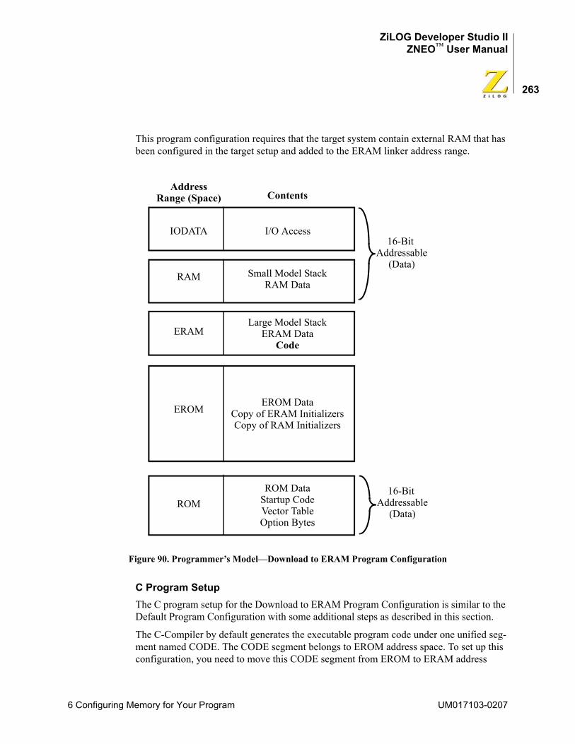
ZiLOG Developer Studio IIZNEO™ User Manual
263
This program configuration requires that the target system contain external RAM that has been configured in the target setup and added to the ERAM linker address range.
Figure 90. Programmer’s Model—Download to ERAM Program Configuration
C Program SetupThe C program setup for the Download to ERAM Program Configuration is similar to the Default Program Configuration with some additional steps as described in this section.
The C-Compiler by default generates the executable program code under one unified seg-ment named CODE. The CODE segment belongs to EROM address space. To set up this configuration, you need to move this CODE segment from EROM to ERAM address
EROM DataCopy of ERAM InitializersCopy of RAM Initializers
Address
IODATA
ERAM
ROM
RAM
EROM
I/O Access
Small Model StackRAM Data
Large Model StackERAM Data
ROM DataStartup CodeVector TableOption Bytes
ContentsRange (Space)
Code
16-Bit Addressable
16-Bit Addressable
(Data)
(Data)
6 Configuring Memory for Your Program UM017103-0207
ZiLOG Developer Studio IIZNEO™ User Manual
264
space. Do this by adding the following linker command in the Additional Linker Direc-tives dialog box (see “Additional Directives” on page 68):
change code=ERAM /* The linker will then allocate code segment in ERAM */
To go back to the Default Program Configuration for production code, remove this direc-tive from the Additional Linker Directives dialog box.
Special Case: Partial Download to ERAM
A special case of this configuration is to download program code from just one C source file into ERAM, while retaining the rest of the code in EROM. This example is included for completeness because similar cases of partitioning the code are discussed for the other configurations that are covered in this chapter. Do this by performing the following steps:
1. Select the Distinct Code Segment for Each Module check box in the Advanced page in the Project Settings dialog box (see page 65).
This option directs the C-Compiler to generate different code segment names for each file.
2. Use the linker CHANGE directive to move the particular segment to ERAM.
For example, to download the code for main.c to ERAM, add the following linker command in the Additional Linker Directives dialog box (see “Additional Directives” on page 68):change main_TEXT = ERAM
To go back to the Default Program Configuration for production code, remove this directive from the Additional Linker Directives dialog box.
Assembly Program SetupThe Assembly program setup for the Download to ERAM Program Configuration is simi-lar to the Default Program Configuration with some additional guidelines as described in this section.
Write all the executable program code (nonstartup code) under the CODE segment. This segment belongs to EROM address space. To set up this configuration, you need to move the CODE segment from EROM to the ERAM address space. Do this by adding the fol-lowing linker command in the Additional Linker Directives dialog box (see “Additional Directives” on page 68):
change code=ERAM /* The linker will then allocate code segment in ERAM */
To go back to the Default Program Configuration for production code, remove this direc-tive from the Additional Linker Directives dialog box.
UM017103-0207 6 Configuring Memory for Your Program
ZiLOG Developer Studio IIZNEO™ User Manual
265
Special Case: Partial Download to ERAM
A special case of this configuration is to download program code from just one assembly segment into ERAM, while retaining the rest of the code in EROM. Do this by performing the following steps:
1. Use a distinct segment name for the particular segment. For example:Define main_TEXT, space=EROMsegment main_TEXT; code goes here
2. Use the linker CHANGE directive to move the particular segment to ERAM. For example:
To download the code for the main_TEXT segment to ERAM, add the following linker command in the Additional Linker Directives dialog box (see “Additional Directives” on page 68):change main_TEXT = ERAM
To go back to the Default Program Configuration for production code, remove this directive from the Additional Linker Directives dialog box.
Download to RAM Program ConfigurationThe Download to RAM Program Configuration (Figure 91) can be used only during development and not for production code. It is similar to the Default Program Configura-tion, the only difference is that the rest of the executable program code is downloaded in RAM and executed from RAM.
6 Configuring Memory for Your Program UM017103-0207
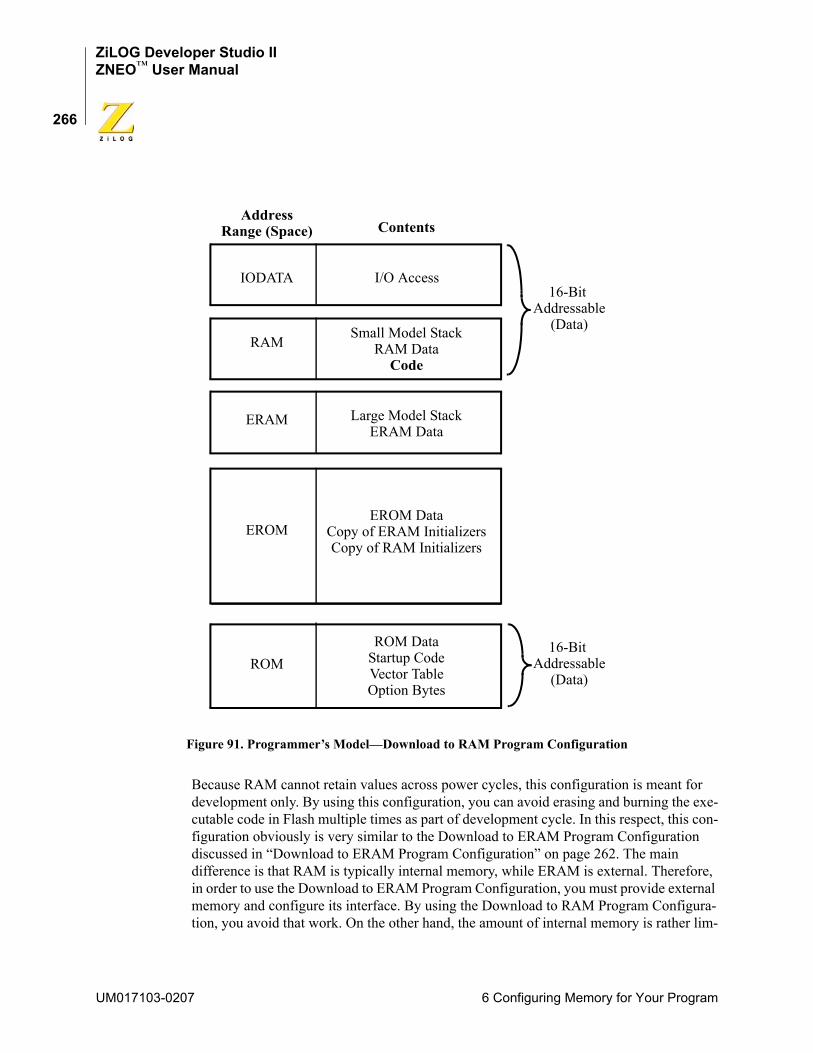
ZiLOG Developer Studio IIZNEO™ User Manual
266
Figure 91. Programmer’s Model—Download to RAM Program Configuration
Because RAM cannot retain values across power cycles, this configuration is meant for development only. By using this configuration, you can avoid erasing and burning the exe-cutable code in Flash multiple times as part of development cycle. In this respect, this con-figuration obviously is very similar to the Download to ERAM Program Configuration discussed in “Download to ERAM Program Configuration” on page 262. The main difference is that RAM is typically internal memory, while ERAM is external. Therefore, in order to use the Download to ERAM Program Configuration, you must provide external memory and configure its interface. By using the Download to RAM Program Configura-tion, you avoid that work. On the other hand, the amount of internal memory is rather lim-
EROM DataCopy of ERAM InitializersCopy of RAM Initializers
16-Bit Addressable
Address
IODATA
ERAM
ROM
RAM
EROM
I/O Access
Small Model StackRAM Data
Large Model StackERAM Data
ROM DataStartup CodeVector TableOption Bytes
ContentsRange (Space)
Code
(Data)
16-Bit Addressable
(Data)
UM017103-0207 6 Configuring Memory for Your Program
ZiLOG Developer Studio IIZNEO™ User Manual
267
ited on many ZNEO devices, so the Download to RAM Program Configuration might tend to be limited to small applications or portions of applications during development.
C Program SetupThe C program setup for Download to RAM Program Configuration is similar to the Default Program Configuration with some additional steps as described in this section.
The C-Compiler by default generates the executable program code under one unified seg-ment named CODE. The CODE segment belongs to EROM address space. To set up this configuration, you need to move the CODE segment from EROM to the RAM address space. Do this by adding the following linker command in the Additional Linker Direc-tives dialog box (see “Additional Directives” on page 68):
change code=RAM /* The linker will then allocate code segment in RAM */
To go back to the Default Program Configuration for production code, remove this direc-tive from the Additional Linker Directives dialog box.
Special Case: Partial Download to RAM
A special case of this configuration is when you want to download program code from just one C source file into RAM, while retaining the rest of the code in EROM. This allows you to experiment with different partitions of your code, for example, if you are consider-ing the Partial Copy to RAM Program Configuration discussed in “Special Case: Partial Copy to RAM” on page 275. Do this by performing the following steps:
1. Select the Distinct Code Segment for Each Module check box in the Advanced page in the Project Settings dialog box (see page 65).
This option directs the C-Compiler to generate different code segment names for each file.
2. Use the linker CHANGE directive to move the particular segment to RAM. For example:
To download the code for main.c to RAM, add the following linker command in the Additional Linker Directives dialog box (see “Additional Directives” on page 68):change main_TEXT = RAM
To go back to the Default Program Configuration for production code, remove this directive from the Additional Linker Directives dialog box.
Assembly Program SetupThe Assembly program setup for the Download to RAM Program Configuration is similar to the Default Program Configuration with some additional guidelines as described in this section.
Write all the executable program code (nonstartup code) under the CODE segment. This segment belongs to EROM address space. To set up this configuration, you need to move
6 Configuring Memory for Your Program UM017103-0207
ZiLOG Developer Studio IIZNEO™ User Manual
268
the CODE segment from EROM to the RAM address space. Do this by adding the follow-ing linker command in the Additional Linker Directives dialog box (see “Additional Directives” on page 68):
change code=RAM /* The linker will then allocate code segment in RAM */
To go back to the Default Program Configuration for production code, remove this direc-tive from the Additional Linker Directives dialog box.
Special Case: Partial Download to RAM
A special case of this configuration is when you want to download program code from just one assembly segment into RAM, while retaining the rest of the code in EROM. This allows you to experiment with different partitions of your code, for instance if you are considering the Partial Copy to RAM Program Configuration discussed in “Special Case: Partial Copy to RAM” on page 275. Do this by performing the following steps:
1. Use a distinct segment name for the particular segment. For example:Define main_TEXT, space=EROMsegment main_TEXT; code goes here
2. Use the linker CHANGE directive to move the particular segment to RAM.
For example, to download the code for the main_TEXT segment to RAM, add the following linker command in the Additional Linker Directives dialog box (see “Additional Directives” on page 68):change main_TEXT = RAM
To go back to the Default Program Configuration for production code, remove this directive from the Additional Linker Directives dialog box.
Copy to ERAM Program ConfigurationThe Copy to ERAM Program Configuration (Figure 92) can be used for production as well as development code. It is somewhat similar to the Default Program Configuration, the only difference being that aside from the startup code, the rest of the executable pro-gram is downloaded into EROM, copied from EROM to ERAM by the startup code, and then executed from ERAM. The reason for choosing this configuration is that while inter-nal Flash on ZNEO-CPU-based devices can be accessed quickly enough to keep up with the CPU, that might not be true of external Flash. If you have both external Flash (as part of the EROM address range) and external RAM (as part of ERAM) in your application and if the external RAM is faster than the external Flash, the user program might execute faster on ERAM. Therefore, this configuration might be advantageous if you want to exe-cute your program from external memory (for example, because your program is too large to fit into internal Flash), but you do not want your execution speed to be limited by the access speed of external Flash memory.
UM017103-0207 6 Configuring Memory for Your Program
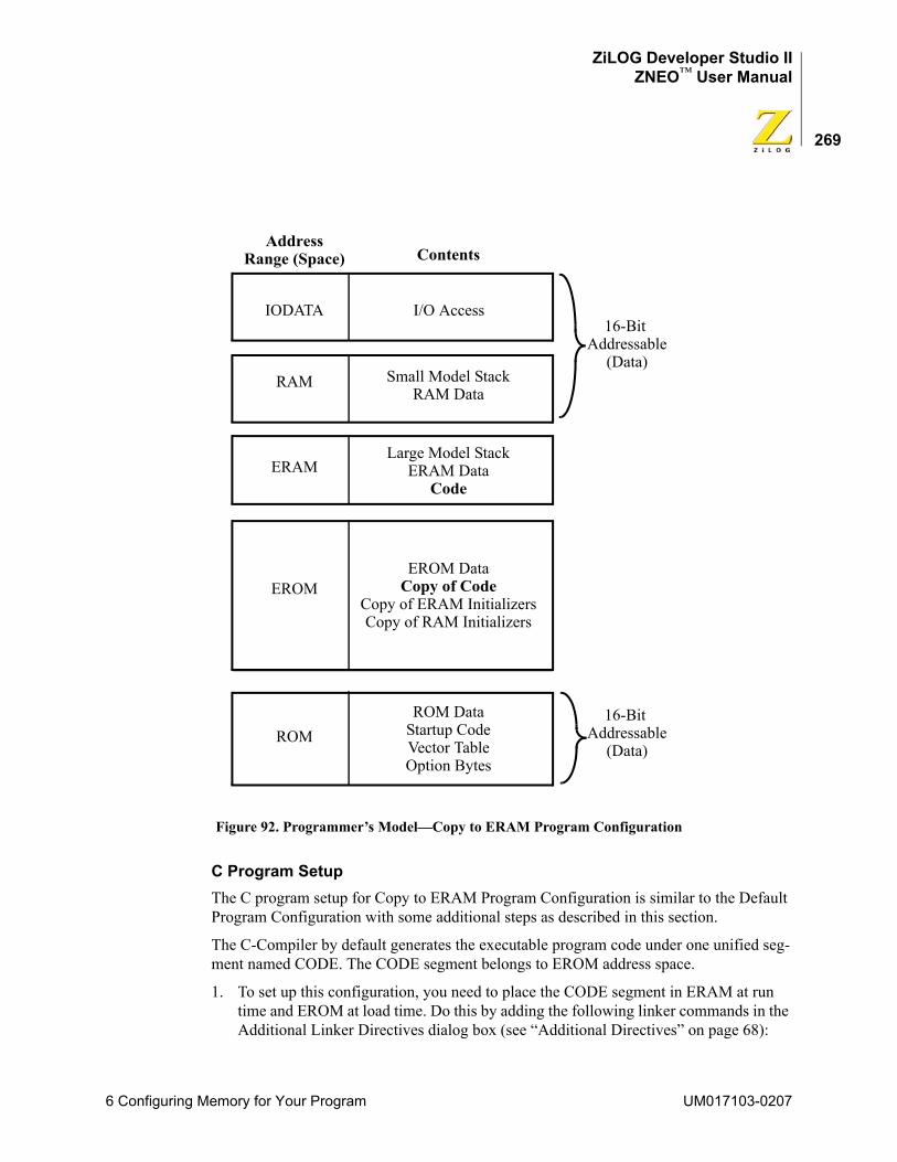
ZiLOG Developer Studio IIZNEO™ User Manual
269
Figure 92. Programmer’s Model—Copy to ERAM Program Configuration
C Program SetupThe C program setup for Copy to ERAM Program Configuration is similar to the Default Program Configuration with some additional steps as described in this section.
The C-Compiler by default generates the executable program code under one unified seg-ment named CODE. The CODE segment belongs to EROM address space.
1. To set up this configuration, you need to place the CODE segment in ERAM at run time and EROM at load time. Do this by adding the following linker commands in the Additional Linker Directives dialog box (see “Additional Directives” on page 68):
EROM DataCopy of Code
Copy of ERAM Initializers
16-Bit Addressable
Address
IODATA
ERAM
ROM
RAM
EROM
I/O Access
Small Model StackRAM Data
Large Model StackERAM Data
ROM DataStartup CodeVector TableOption Bytes
ContentsRange (Space)
Code
Copy of RAM Initializers
(Data)
16-Bit Addressable
(Data)
6 Configuring Memory for Your Program UM017103-0207
ZiLOG Developer Studio IIZNEO™ User Manual
270
change code=ERAM /* Run time CODE is in ERAM space */copy code EROM /* Load time CODE is in EROM space */
define _low_code_copy = copy base of CODEdefine _low_code = base of CODEdefine _len_code = length of CODE
2. The linker COPY directive only designates the load addresses and the run-time addresses for the segment. The actual copying of the segment must be performed by the startup code. For example if you are using the small model, copy and modify the C startup provided in the installation under src\boot\common\startupexs.asm, rewriting the relevant section as follows:;; Copy CODE into ERAM;
LEA R0,_low_code_copyLEA R1,_low_codeLD R2,#_len_code+1JP clab1
clab0:LD.B R3,(R0++)LD.B (R1++),R3
clab1:DJNZ R2,clab0
XREF _low_code_copy:EROMXREF _len_code:ERAMXREF _low_code:ERAM
3. Finally, add your modified startup module to your project. To do this, you must select the Included in Project button in the Objects and Libraries page of the Project Settings dialog box (see “C Startup Module” on page 72) and also add the modified source code file to your project using the Add Files command from the Project menu.
Special Case: Partial Copy to ERAM
A special case of this configuration is when you want to copy program code from just one C source file into ERAM, while retaining the rest of the code in EROM. This allows you to gain the potential speed advantages of external RAM over external Flash for a specific module. Do this by performing the following steps:
1. Select the Distinct Code Segment for Each Module check box in the Advanced page in the Project Settings dialog box (see page 65).
This directs the C-Compiler to generate different code segment names for each file.
2. Add the linker commands to place the particular segment in ERAM at run time and EROM at load time.
UM017103-0207 6 Configuring Memory for Your Program
ZiLOG Developer Studio IIZNEO™ User Manual
271
For example, to copy the code for main.c to ERAM, add the following linker commands in the Additional Linker Directives dialog box (see “Additional Directives” on page 68):change main_TEXT=ERAM /* Run time main_TEXT is in ERAM space */copy main_TEXT EROM /* Load time main_TEXT is in EROM space */
define _low_main_copy = copy base of main_TEXTdefine _low_main = base of main_TEXTdefine _len_main = length of main_TEXT
3. The linker COPY directive only designates the load addresses and the run-time addresses for the segment. The actual copying of the segment needs to be performed by the startup code. For example, if you are using the small model, copy and modify the C startup provided in the installation under src\boot\common\startupexs.asm, rewriting the relevant section as follows:;; Copy main_TEXT into ERAM;
LEA R0,_low_main_copyLEA R1,_low_mainLD R2,#_len_main+1JP mlab1
mlab0:LD.B R3,(R0++)LD.B (R1++),R3
mlab1:DJNZ R2,mlab0
XREF _low_main_copy:EROMXREF _len_main:ERAMXREF _low_main:ERAM
4. Finally, add your modified startup module to your project. To do this, you must select the Included in Project button in the Objects and Libraries page of the Project Settings dialog box (see “C Startup Module” on page 72) and also add the modified source code file to your project using the Add Files command from the Project menu.
Assembly Program SetupThe Assembly program setup for the Copy to ERAM Program Configuration is similar to the Default Program Configuration with some additional guidelines as described in this section.
Write all the executable program code (nonstartup code) under the CODE segment. This segment belongs to EROM address space. To set up this configuration, you need to copy the CODE segment from EROM to the ERAM address space. Do this by performing steps 2 and 3 from the C Program Setup for this configuration, as described in “C Program
6 Configuring Memory for Your Program UM017103-0207
ZiLOG Developer Studio IIZNEO™ User Manual
272
Setup” on page 269. In step 3, add the code to your assembly startup code instead of the standard C startup.
Special Case: Partial Copy to ERAM
A special case of this configuration is when you want to copy program code from just one assembly segment into ERAM, while retaining the rest of the code in EROM. This allows you to gain the potential speed advantages of external RAM over external Flash for a spe-cific module. Do this by performing the following steps:
1. Use a distinct segment name for the particular segment. For example:Define main_TEXT, space=EROMsegment main_TEXT; code goes here
2. To copy the main_TEXT segment from EROM to the ERAM address space, perform steps 2 and 3 from the C Program Setup, Special Case, for this configuration as described in “C Program Setup” on page 269. In step 3, add the code to your assembly startup code instead of the standard C startup.
Copy to RAM Program ConfigurationThe Copy to RAM Program Configuration (Figure 93) can be used for production as well as development code. It is somewhat similar to the Default Program Configuration, the only difference being that the executable program code is downloaded in EROM, copied from EROM to RAM by the startup code, and then executed from RAM. The reason for choosing this configuration is that while internal Flash on ZNEO-CPU-based devices can be accessed quickly enough to keep up with the CPU, that might not be true of external Flash. If you have external Flash (as part of the EROM address space) and if the internal RAM is faster than the external Flash, the user program might execute faster from RAM.
UM017103-0207 6 Configuring Memory for Your Program
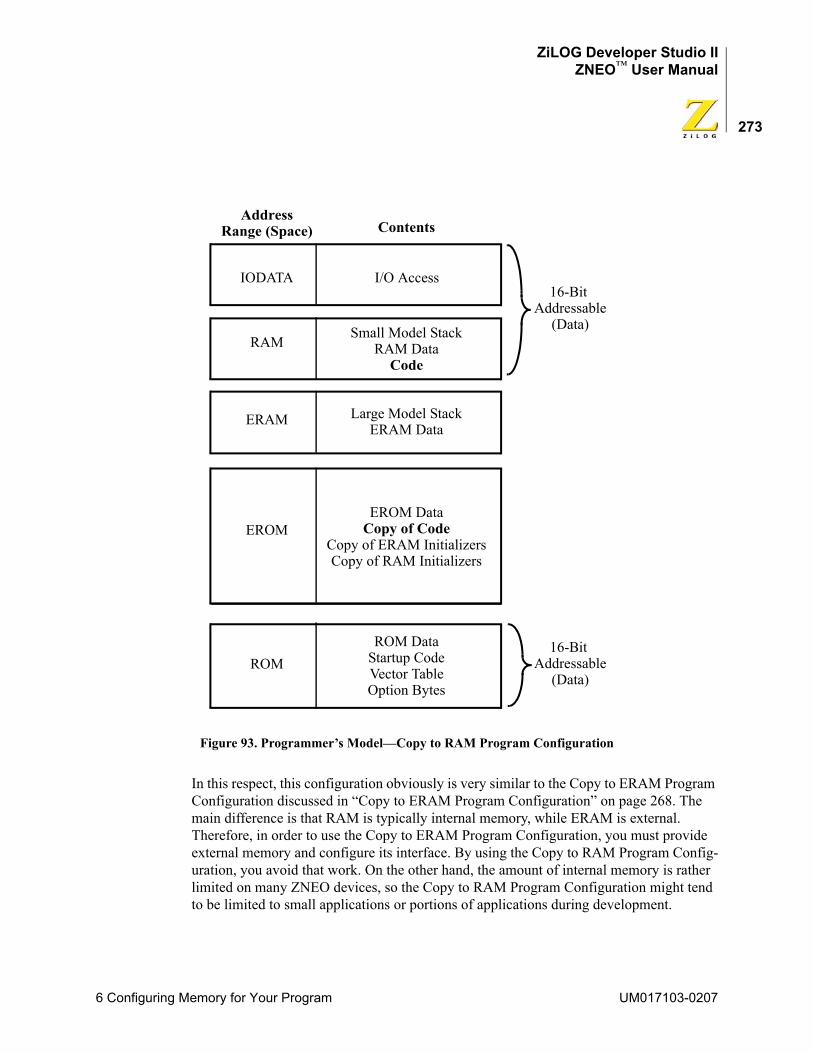
ZiLOG Developer Studio IIZNEO™ User Manual
273
Figure 93. Programmer’s Model—Copy to RAM Program Configuration
In this respect, this configuration obviously is very similar to the Copy to ERAM Program Configuration discussed in “Copy to ERAM Program Configuration” on page 268. The main difference is that RAM is typically internal memory, while ERAM is external. Therefore, in order to use the Copy to ERAM Program Configuration, you must provide external memory and configure its interface. By using the Copy to RAM Program Config-uration, you avoid that work. On the other hand, the amount of internal memory is rather limited on many ZNEO devices, so the Copy to RAM Program Configuration might tend to be limited to small applications or portions of applications during development.
EROM DataCopy of Code
Copy of ERAM Initializers
16-Bit Addressable
Address
IODATA
ERAM
ROM
RAM
EROM
I/O Access
Small Model StackRAM Data
Large Model StackERAM Data
ROM DataStartup CodeVector TableOption Bytes
ContentsRange (Space)
Copy of RAM Initializers
Code
(Data)
16-Bit Addressable
(Data)
6 Configuring Memory for Your Program UM017103-0207
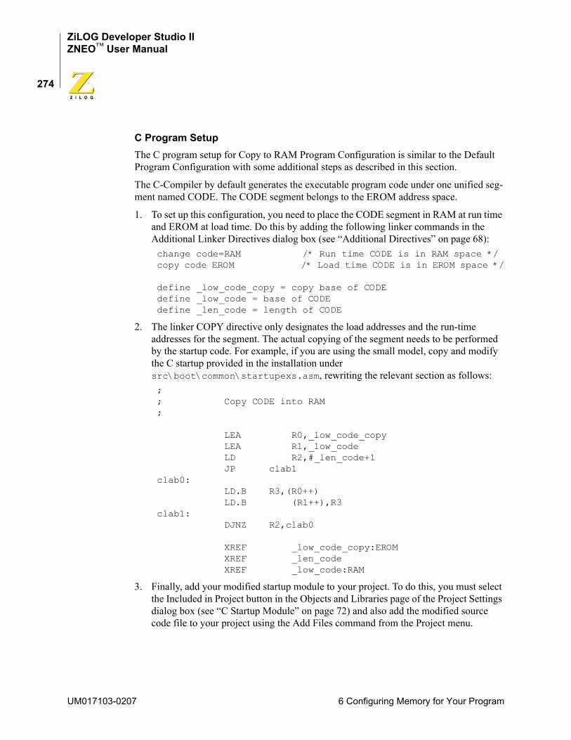
ZiLOG Developer Studio IIZNEO™ User Manual
274
C Program SetupThe C program setup for Copy to RAM Program Configuration is similar to the Default Program Configuration with some additional steps as described in this section.
The C-Compiler by default generates the executable program code under one unified seg-ment named CODE. The CODE segment belongs to the EROM address space.
1. To set up this configuration, you need to place the CODE segment in RAM at run time and EROM at load time. Do this by adding the following linker commands in the Additional Linker Directives dialog box (see “Additional Directives” on page 68):change code=RAM /* Run time CODE is in RAM space */copy code EROM /* Load time CODE is in EROM space */
define _low_code_copy = copy base of CODEdefine _low_code = base of CODEdefine _len_code = length of CODE
2. The linker COPY directive only designates the load addresses and the run-time addresses for the segment. The actual copying of the segment needs to be performed by the startup code. For example, if you are using the small model, copy and modify the C startup provided in the installation under src\boot\common\startupexs.asm, rewriting the relevant section as follows:;; Copy CODE into RAM;
LEA R0,_low_code_copyLEA R1,_low_codeLD R2,#_len_code+1JP clab1
clab0:LD.B R3,(R0++)LD.B (R1++),R3
clab1:DJNZ R2,clab0
XREF _low_code_copy:EROMXREF _len_codeXREF _low_code:RAM
3. Finally, add your modified startup module to your project. To do this, you must select the Included in Project button in the Objects and Libraries page of the Project Settings dialog box (see “C Startup Module” on page 72) and also add the modified source code file to your project using the Add Files command from the Project menu.
UM017103-0207 6 Configuring Memory for Your Program
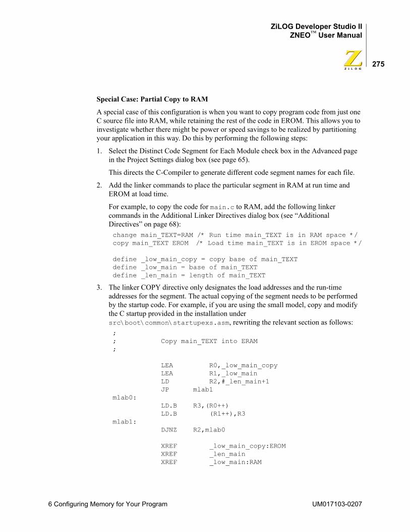
ZiLOG Developer Studio IIZNEO™ User Manual
275
Special Case: Partial Copy to RAM
A special case of this configuration is when you want to copy program code from just one C source file into RAM, while retaining the rest of the code in EROM. This allows you to investigate whether there might be power or speed savings to be realized by partitioning your application in this way. Do this by performing the following steps:
1. Select the Distinct Code Segment for Each Module check box in the Advanced page in the Project Settings dialog box (see page 65).
This directs the C-Compiler to generate different code segment names for each file.
2. Add the linker commands to place the particular segment in RAM at run time and EROM at load time.
For example, to copy the code for main.c to RAM, add the following linker commands in the Additional Linker Directives dialog box (see “Additional Directives” on page 68):change main_TEXT=RAM /* Run time main_TEXT is in RAM space */copy main_TEXT EROM /* Load time main_TEXT is in EROM space */
define _low_main_copy = copy base of main_TEXTdefine _low_main = base of main_TEXTdefine _len_main = length of main_TEXT
3. The linker COPY directive only designates the load addresses and the run-time addresses for the segment. The actual copying of the segment needs to be performed by the startup code. For example, if you are using the small model, copy and modify the C startup provided in the installation under src\boot\common\startupexs.asm, rewriting the relevant section as follows:;; Copy main_TEXT into ERAM;
LEA R0,_low_main_copyLEA R1,_low_mainLD R2,#_len_main+1JP mlab1
mlab0:LD.B R3,(R0++)LD.B (R1++),R3
mlab1:DJNZ R2,mlab0
XREF _low_main_copy:EROMXREF _len_mainXREF _low_main:RAM
6 Configuring Memory for Your Program UM017103-0207
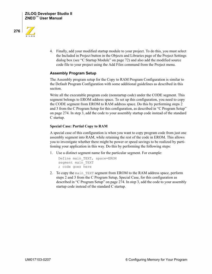
ZiLOG Developer Studio IIZNEO™ User Manual
276
4. Finally, add your modified startup module to your project. To do this, you must select the Included in Project button in the Objects and Libraries page of the Project Settings dialog box (see “C Startup Module” on page 72) and also add the modified source code file to your project using the Add Files command from the Project menu.
Assembly Program SetupThe Assembly program setup for the Copy to RAM Program Configuration is similar to the Default Program Configuration with some additional guidelines as described in this section.
Write all the executable program code (nonstartup code) under the CODE segment. This segment belongs to EROM address space. To set up this configuration, you need to copy the CODE segment from EROM to RAM address space. Do this by performing steps 2 and 3 from the C Program Setup for this configuration, as described in “C Program Setup” on page 274. In step 3, add the code to your assembly startup code instead of the standard C startup.
Special Case: Partial Copy to RAM
A special case of this configuration is when you want to copy program code from just one assembly segment into RAM, while retaining the rest of the code in EROM. This allows you to investigate whether there might be power or speed savings to be realized by parti-tioning your application in this way. Do this by performing the following steps:
1. Use a distinct segment name for the particular segment. For example:Define main_TEXT, space=EROMsegment main_TEXT; code goes here
2. To copy the main_TEXT segment from EROM to the RAM address space, perform steps 2 and 3 from the C Program Setup, Special Case, for this configuration as described in “C Program Setup” on page 274. In step 3, add the code to your assembly startup code instead of the standard C startup.
UM017103-0207 6 Configuring Memory for Your Program
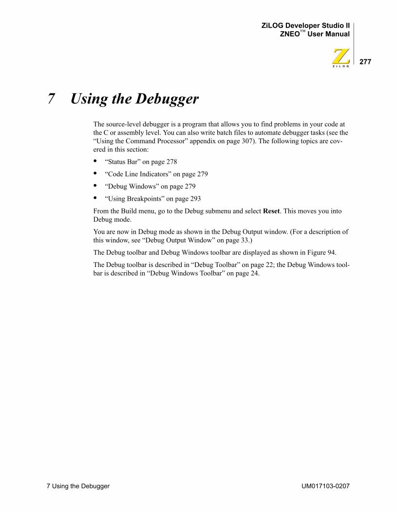
ZiLOG Developer Studio IIZNEO™ User Manual
277
7 Using the DebuggerThe source-level debugger is a program that allows you to find problems in your code at the C or assembly level. You can also write batch files to automate debugger tasks (see the “Using the Command Processor” appendix on page 307). The following topics are cov-ered in this section:
• “Status Bar” on page 278
• “Code Line Indicators” on page 279
• “Debug Windows” on page 279
• “Using Breakpoints” on page 293
From the Build menu, go to the Debug submenu and select Reset. This moves you into Debug mode.
You are now in Debug mode as shown in the Debug Output window. (For a description of this window, see “Debug Output Window” on page 33.)
The Debug toolbar and Debug Windows toolbar are displayed as shown in Figure 94.
The Debug toolbar is described in “Debug Toolbar” on page 22; the Debug Windows tool-bar is described in “Debug Windows Toolbar” on page 24.
7 Using the Debugger UM017103-0207
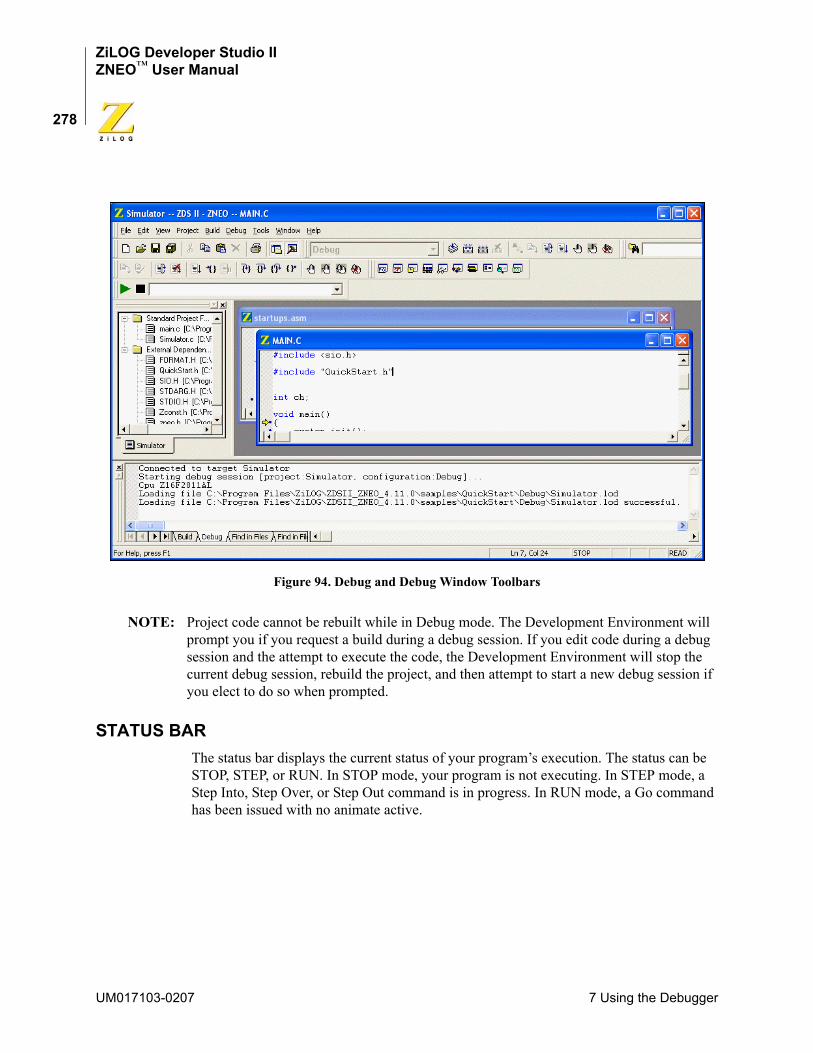
ZiLOG Developer Studio IIZNEO™ User Manual
278
Figure 94. Debug and Debug Window Toolbars
NOTE: Project code cannot be rebuilt while in Debug mode. The Development Environment will prompt you if you request a build during a debug session. If you edit code during a debug session and the attempt to execute the code, the Development Environment will stop the current debug session, rebuild the project, and then attempt to start a new debug session if you elect to do so when prompted.
STATUS BARThe status bar displays the current status of your program’s execution. The status can be STOP, STEP, or RUN. In STOP mode, your program is not executing. In STEP mode, a Step Into, Step Over, or Step Out command is in progress. In RUN mode, a Go command has been issued with no animate active.
UM017103-0207 7 Using the Debugger
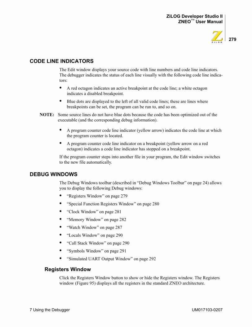
ZiLOG Developer Studio IIZNEO™ User Manual
279
CODE LINE INDICATORSThe Edit window displays your source code with line numbers and code line indicators. The debugger indicates the status of each line visually with the following code line indica-tors:
• A red octagon indicates an active breakpoint at the code line; a white octagon indicates a disabled breakpoint.
• Blue dots are displayed to the left of all valid code lines; these are lines where breakpoints can be set, the program can be run to, and so on.
NOTE: Some source lines do not have blue dots because the code has been optimized out of the executable (and the corresponding debug information).
• A program counter code line indicator (yellow arrow) indicates the code line at which the program counter is located.
• A program counter code line indicator on a breakpoint (yellow arrow on a red octagon) indicates a code line indicator has stopped on a breakpoint.
If the program counter steps into another file in your program, the Edit window switches to the new file automatically.
DEBUG WINDOWSThe Debug Windows toolbar (described in “Debug Windows Toolbar” on page 24) allows you to display the following Debug windows:
• “Registers Window” on page 279
• “Special Function Registers Window” on page 280
• “Clock Window” on page 281
• “Memory Window” on page 282
• “Watch Window” on page 287
• “Locals Window” on page 290
• “Call Stack Window” on page 290
• “Symbols Window” on page 291
• “Simulated UART Output Window” on page 292
Registers WindowClick the Registers Window button to show or hide the Registers window. The Registers window (Figure 95) displays all the registers in the standard ZNEO architecture.
7 Using the Debugger UM017103-0207
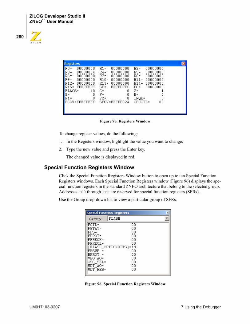
ZiLOG Developer Studio IIZNEO™ User Manual
280
Figure 95. Registers Window
To change register values, do the following:
1. In the Registers window, highlight the value you want to change.
2. Type the new value and press the Enter key.
The changed value is displayed in red.
Special Function Registers WindowClick the Special Function Registers Window button to open up to ten Special Function Registers windows. Each Special Function Registers window (Figure 96) displays the spe-cial function registers in the standard ZNEO architecture that belong to the selected group. Addresses F00 through FFF are reserved for special function registers (SFRs).
Use the Group drop-down list to view a particular group of SFRs.
Figure 96. Special Function Registers Window
UM017103-0207 7 Using the Debugger
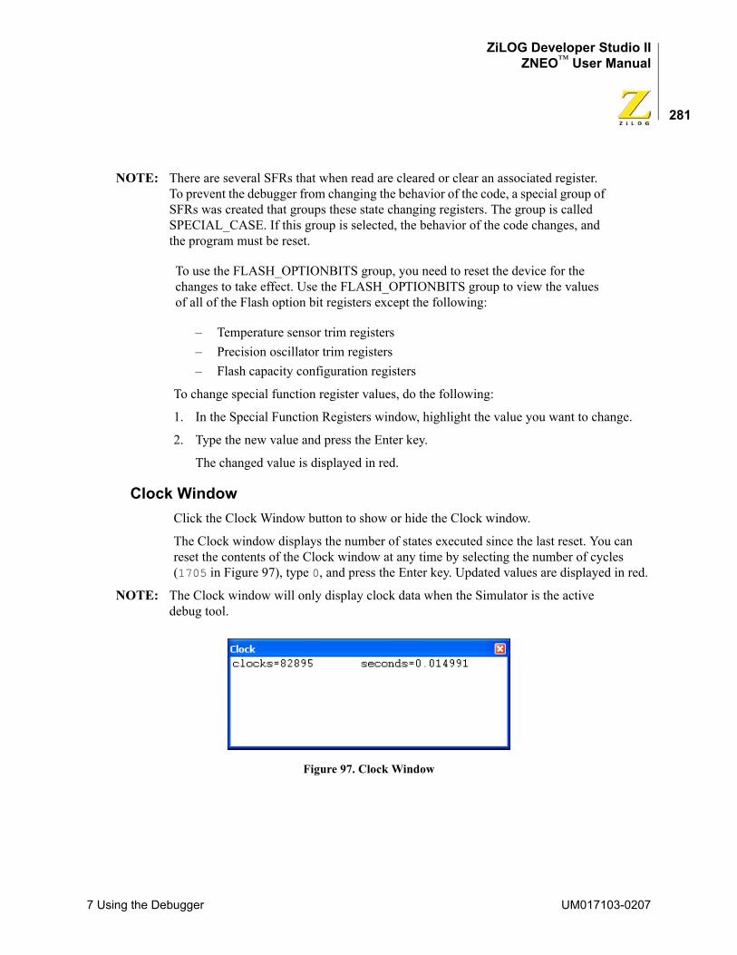
ZiLOG Developer Studio IIZNEO™ User Manual
281
NOTE: There are several SFRs that when read are cleared or clear an associated register. To prevent the debugger from changing the behavior of the code, a special group of SFRs was created that groups these state changing registers. The group is called SPECIAL_CASE. If this group is selected, the behavior of the code changes, and the program must be reset.
To use the FLASH_OPTIONBITS group, you need to reset the device for the changes to take effect. Use the FLASH_OPTIONBITS group to view the values of all of the Flash option bit registers except the following:
– Temperature sensor trim registers– Precision oscillator trim registers– Flash capacity configuration registers
To change special function register values, do the following:
1. In the Special Function Registers window, highlight the value you want to change.
2. Type the new value and press the Enter key.
The changed value is displayed in red.
Clock WindowClick the Clock Window button to show or hide the Clock window.
The Clock window displays the number of states executed since the last reset. You can reset the contents of the Clock window at any time by selecting the number of cycles (1705 in Figure 97), type 0, and press the Enter key. Updated values are displayed in red.
NOTE: The Clock window will only display clock data when the Simulator is the active debug tool.
Figure 97. Clock Window
7 Using the Debugger UM017103-0207
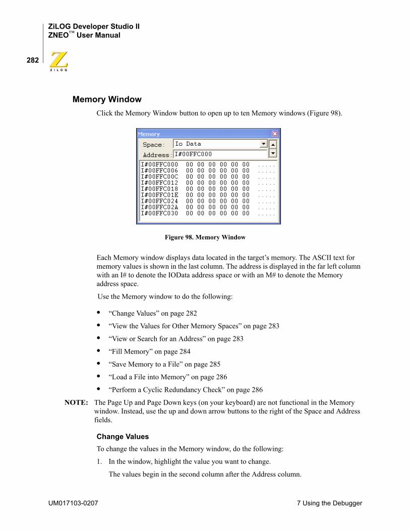
ZiLOG Developer Studio IIZNEO™ User Manual
282
Memory WindowClick the Memory Window button to open up to ten Memory windows (Figure 98).
Figure 98. Memory Window
Each Memory window displays data located in the target’s memory. The ASCII text for memory values is shown in the last column. The address is displayed in the far left column with an I# to denote the IOData address space or with an M# to denote the Memory address space.
Use the Memory window to do the following:
• “Change Values” on page 282
• “View the Values for Other Memory Spaces” on page 283
• “View or Search for an Address” on page 283
• “Fill Memory” on page 284
• “Save Memory to a File” on page 285
• “Load a File into Memory” on page 286
• “Perform a Cyclic Redundancy Check” on page 286
NOTE: The Page Up and Page Down keys (on your keyboard) are not functional in the Memory window. Instead, use the up and down arrow buttons to the right of the Space and Address fields.
Change ValuesTo change the values in the Memory window, do the following:
1. In the window, highlight the value you want to change.
The values begin in the second column after the Address column.
UM017103-0207 7 Using the Debugger
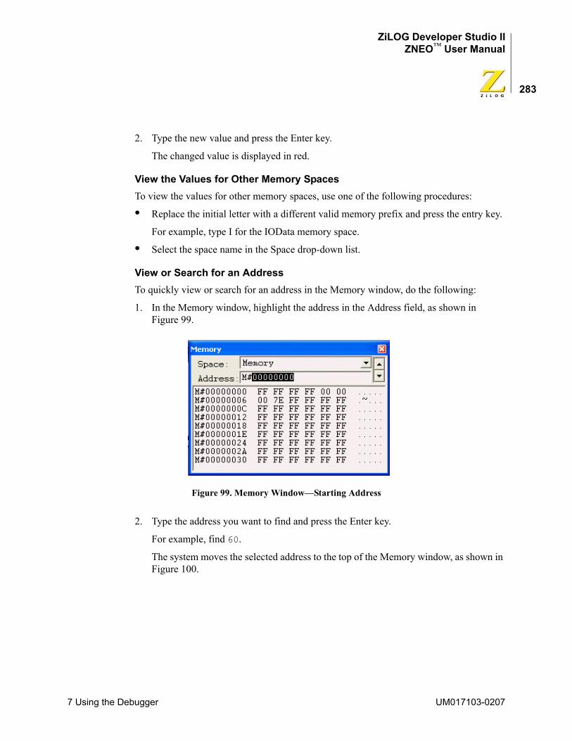
ZiLOG Developer Studio IIZNEO™ User Manual
283
2. Type the new value and press the Enter key.
The changed value is displayed in red.
View the Values for Other Memory SpacesTo view the values for other memory spaces, use one of the following procedures:
• Replace the initial letter with a different valid memory prefix and press the entry key.
For example, type I for the IOData memory space.
• Select the space name in the Space drop-down list.
View or Search for an AddressTo quickly view or search for an address in the Memory window, do the following:
1. In the Memory window, highlight the address in the Address field, as shown in Figure 99.
Figure 99. Memory Window—Starting Address
2. Type the address you want to find and press the Enter key.
For example, find 60.
The system moves the selected address to the top of the Memory window, as shown in Figure 100.
7 Using the Debugger UM017103-0207
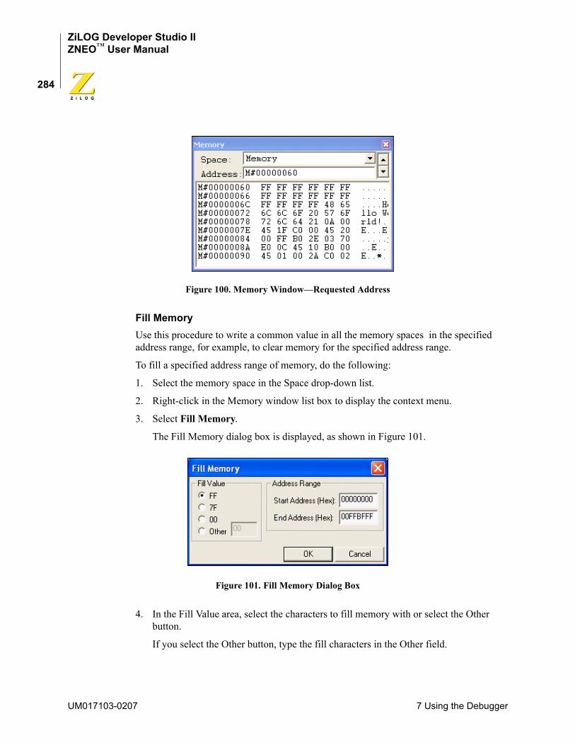
ZiLOG Developer Studio IIZNEO™ User Manual
284
Figure 100. Memory Window—Requested Address
Fill MemoryUse this procedure to write a common value in all the memory spaces in the specified address range, for example, to clear memory for the specified address range.
To fill a specified address range of memory, do the following:
1. Select the memory space in the Space drop-down list.
2. Right-click in the Memory window list box to display the context menu.
3. Select Fill Memory.
The Fill Memory dialog box is displayed, as shown in Figure 101.
Figure 101. Fill Memory Dialog Box
4. In the Fill Value area, select the characters to fill memory with or select the Other button.
If you select the Other button, type the fill characters in the Other field.
UM017103-0207 7 Using the Debugger
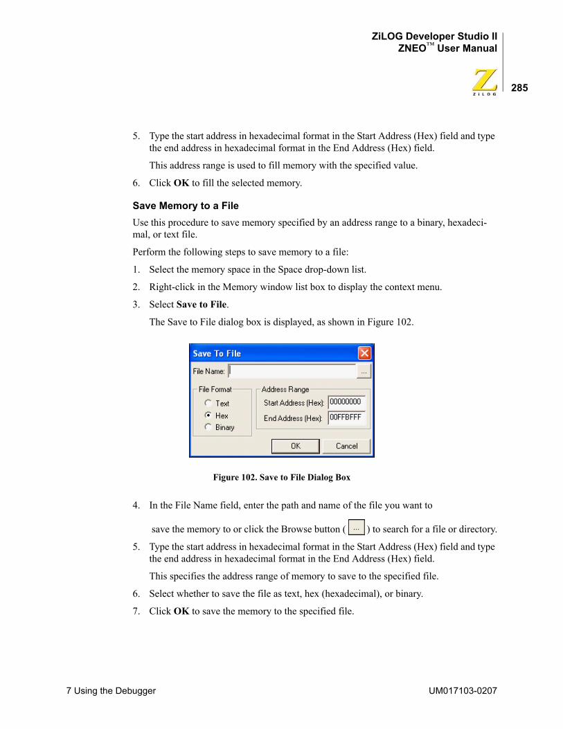
ZiLOG Developer Studio IIZNEO™ User Manual
285
5. Type the start address in hexadecimal format in the Start Address (Hex) field and type the end address in hexadecimal format in the End Address (Hex) field.
This address range is used to fill memory with the specified value.
6. Click OK to fill the selected memory.
Save Memory to a FileUse this procedure to save memory specified by an address range to a binary, hexadeci-mal, or text file.
Perform the following steps to save memory to a file:
1. Select the memory space in the Space drop-down list.
2. Right-click in the Memory window list box to display the context menu.
3. Select Save to File.
The Save to File dialog box is displayed, as shown in Figure 102.
Figure 102. Save to File Dialog Box
4. In the File Name field, enter the path and name of the file you want to save the memory to or click the Browse button ( ) to search for a file or directory.
5. Type the start address in hexadecimal format in the Start Address (Hex) field and type the end address in hexadecimal format in the End Address (Hex) field.
This specifies the address range of memory to save to the specified file.
6. Select whether to save the file as text, hex (hexadecimal), or binary.
7. Click OK to save the memory to the specified file.
7 Using the Debugger UM017103-0207
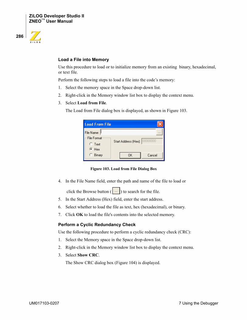
ZiLOG Developer Studio IIZNEO™ User Manual
286
Load a File into MemoryUse this procedure to load or to initialize memory from an existing binary, hexadecimal, or text file.
Perform the following steps to load a file into the code’s memory:
1. Select the memory space in the Space drop-down list.
2. Right-click in the Memory window list box to display the context menu.
3. Select Load from File.
The Load from File dialog box is displayed, as shown in Figure 103.
Figure 103. Load from File Dialog Box
4. In the File Name field, enter the path and name of the file to load or click the Browse button ( ) to search for the file.
5. In the Start Address (Hex) field, enter the start address.
6. Select whether to load the file as text, hex (hexadecimal), or binary.
7. Click OK to load the file's contents into the selected memory.
Perform a Cyclic Redundancy CheckUse the following procedure to perform a cyclic redundancy check (CRC):
1. Select the Memory space in the Space drop-down list.
2. Right-click in the Memory window list box to display the context menu.
3. Select Show CRC.
The Show CRC dialog box (Figure 104) is displayed.
UM017103-0207 7 Using the Debugger
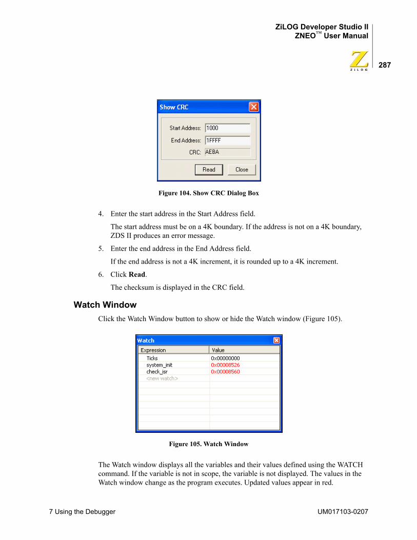
ZiLOG Developer Studio IIZNEO™ User Manual
287
Figure 104. Show CRC Dialog Box
4. Enter the start address in the Start Address field.
The start address must be on a 4K boundary. If the address is not on a 4K boundary, ZDS II produces an error message.
5. Enter the end address in the End Address field.
If the end address is not a 4K increment, it is rounded up to a 4K increment.
6. Click Read.
The checksum is displayed in the CRC field.
Watch WindowClick the Watch Window button to show or hide the Watch window (Figure 105).
Figure 105. Watch Window
The Watch window displays all the variables and their values defined using the WATCH command. If the variable is not in scope, the variable is not displayed. The values in the Watch window change as the program executes. Updated values appear in red.
7 Using the Debugger UM017103-0207
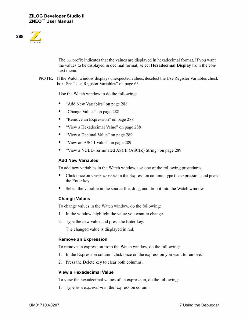
ZiLOG Developer Studio IIZNEO™ User Manual
288
The 0x prefix indicates that the values are displayed in hexadecimal format. If you want the values to be displayed in decimal format, select Hexadecimal Display from the con-text menu.
NOTE: If the Watch window displays unexpected values, deselect the Use Register Variables check box. See “Use Register Variables” on page 63.
Use the Watch window to do the following:
• “Add New Variables” on page 288
• “Change Values” on page 288
• “Remove an Expression” on page 288
• “View a Hexadecimal Value” on page 288
• “View a Decimal Value” on page 289
• “View an ASCII Value” on page 289
• “View a NULL-Terminated ASCII (ASCIZ) String” on page 289
Add New VariablesTo add new variables in the Watch window, use one of the following procedures:
• Click once on <new watch> in the Expression column, type the expression, and press the Enter key.
• Select the variable in the source file, drag, and drop it into the Watch window.
Change ValuesTo change values in the Watch window, do the following:
1. In the window, highlight the value you want to change.
2. Type the new value and press the Enter key.
The changed value is displayed in red.
Remove an ExpressionTo remove an expression from the Watch window, do the following:
1. In the Expression column, click once on the expression you want to remove.
2. Press the Delete key to clear both columns.
View a Hexadecimal ValueTo view the hexadecimal values of an expression, do the following:
1. Type hex expression in the Expression column
UM017103-0207 7 Using the Debugger
ZiLOG Developer Studio IIZNEO™ User Manual
289
For example, type hex tens.
NOTE: You can also type just the expression (for example, type tens) to view the hexadecimal value of any expression. Hexadecimal format is the default.
2. Press the Enter key.
The hexadecimal value displays in the Value column.
To view the hexadecimal values for all expressions, select Hexadecimal Display from the context menu.
View a Decimal ValueTo view the decimal values of an expression, do the following:
1. Type dec expression in the Expression column
For example, type dec huns.
2. Press the Enter key.
The decimal value displays in the Value column.
To view the decimal values for all expressions, select Hexadecimal Display from the context menu.
View an ASCII ValueTo view the ASCII values of an expression, do the following:
1. Type ascii expression in the Expression column.
For example, type ascii ones.
2. Press the Enter key.
The ASCII value displays in the Value column.
View a NULL-Terminated ASCII (ASCIZ) StringTo view the NULL-terminated ASCII (ASCIZ) values of an expression, do the following:
1. Type asciz expression in the Expression column
For example, type asciz ones.
2. Press the Enter key.
The ASCIZ value displays in the Value column.
7 Using the Debugger UM017103-0207
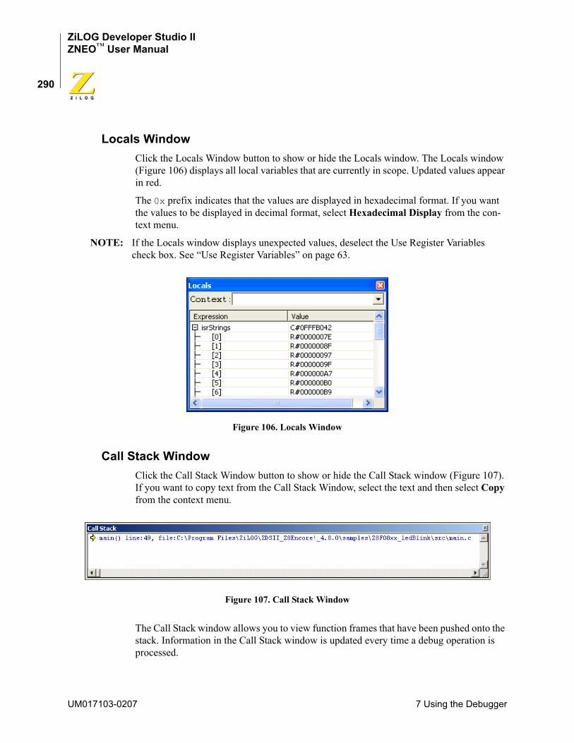
ZiLOG Developer Studio IIZNEO™ User Manual
290
Locals WindowClick the Locals Window button to show or hide the Locals window. The Locals window (Figure 106) displays all local variables that are currently in scope. Updated values appear in red.
The 0x prefix indicates that the values are displayed in hexadecimal format. If you want the values to be displayed in decimal format, select Hexadecimal Display from the con-text menu.
NOTE: If the Locals window displays unexpected values, deselect the Use Register Variables check box. See “Use Register Variables” on page 63.
Figure 106. Locals Window
Call Stack WindowClick the Call Stack Window button to show or hide the Call Stack window (Figure 107). If you want to copy text from the Call Stack Window, select the text and then select Copy from the context menu.
Figure 107. Call Stack Window
The Call Stack window allows you to view function frames that have been pushed onto the stack. Information in the Call Stack window is updated every time a debug operation is processed.
UM017103-0207 7 Using the Debugger
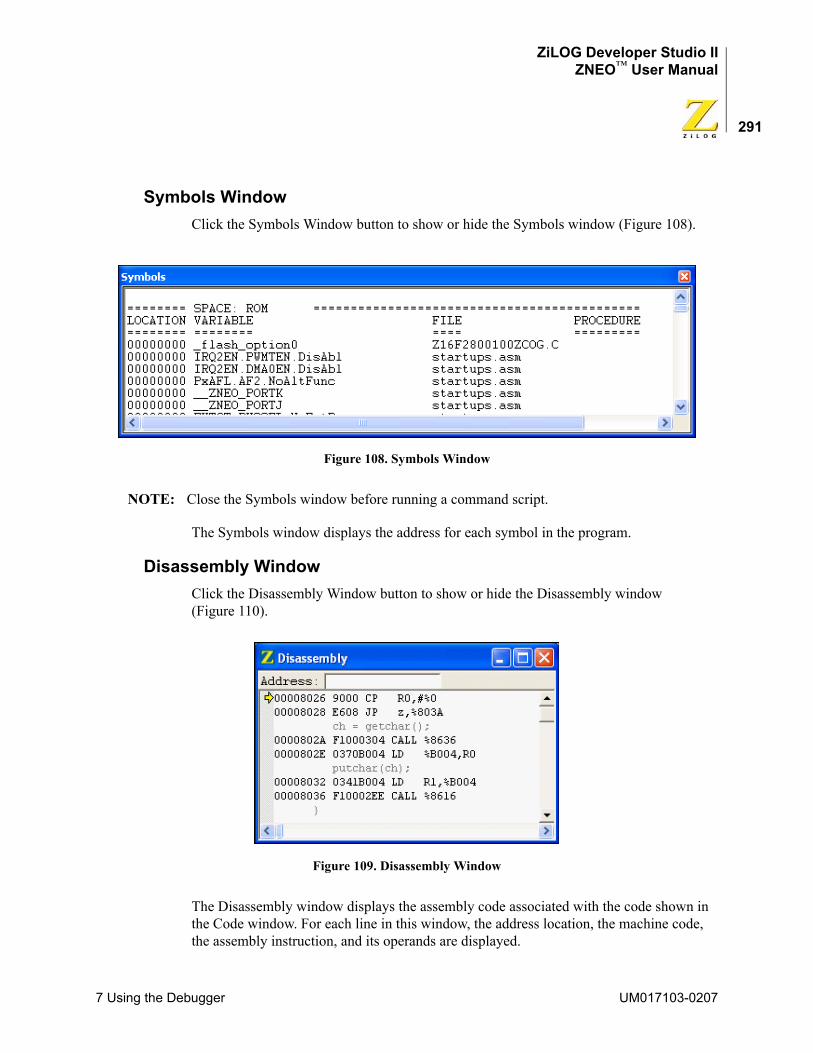
ZiLOG Developer Studio IIZNEO™ User Manual
291
Symbols WindowClick the Symbols Window button to show or hide the Symbols window (Figure 108).
Figure 108. Symbols Window
NOTE: Close the Symbols window before running a command script.
The Symbols window displays the address for each symbol in the program.
Disassembly WindowClick the Disassembly Window button to show or hide the Disassembly window (Figure 110).
Figure 109. Disassembly Window
The Disassembly window displays the assembly code associated with the code shown in the Code window. For each line in this window, the address location, the machine code, the assembly instruction, and its operands are displayed.
7 Using the Debugger UM017103-0207
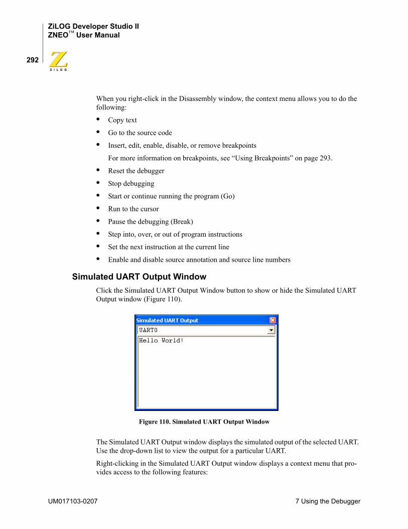
ZiLOG Developer Studio IIZNEO™ User Manual
292
When you right-click in the Disassembly window, the context menu allows you to do the following:
• Copy text
• Go to the source code
• Insert, edit, enable, disable, or remove breakpoints
For more information on breakpoints, see “Using Breakpoints” on page 293.
• Reset the debugger
• Stop debugging
• Start or continue running the program (Go)
• Run to the cursor
• Pause the debugging (Break)
• Step into, over, or out of program instructions
• Set the next instruction at the current line
• Enable and disable source annotation and source line numbers
Simulated UART Output WindowClick the Simulated UART Output Window button to show or hide the Simulated UART Output window (Figure 110).
Figure 110. Simulated UART Output Window
The Simulated UART Output window displays the simulated output of the selected UART. Use the drop-down list to view the output for a particular UART.
Right-clicking in the Simulated UART Output window displays a context menu that pro-vides access to the following features:
UM017103-0207 7 Using the Debugger
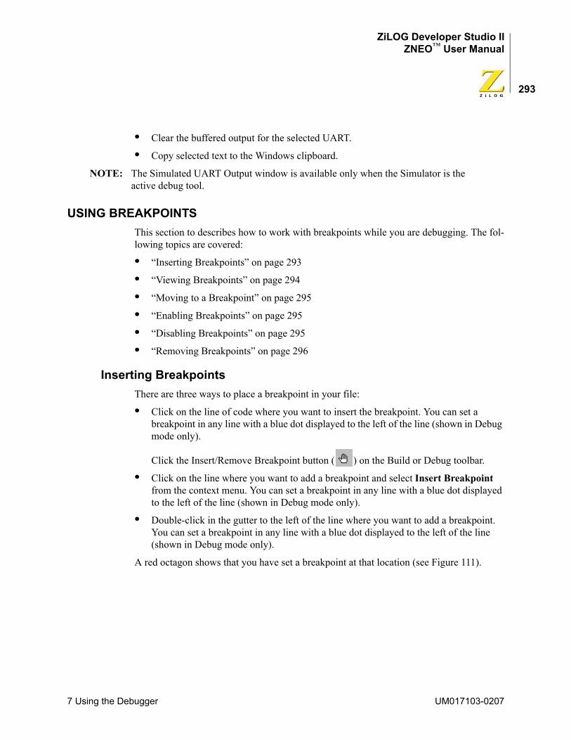
ZiLOG Developer Studio IIZNEO™ User Manual
293
• Clear the buffered output for the selected UART.
• Copy selected text to the Windows clipboard.
NOTE: The Simulated UART Output window is available only when the Simulator is the active debug tool.
USING BREAKPOINTSThis section to describes how to work with breakpoints while you are debugging. The fol-lowing topics are covered:
• “Inserting Breakpoints” on page 293
• “Viewing Breakpoints” on page 294
• “Moving to a Breakpoint” on page 295
• “Enabling Breakpoints” on page 295
• “Disabling Breakpoints” on page 295
• “Removing Breakpoints” on page 296
Inserting BreakpointsThere are three ways to place a breakpoint in your file:
• Click on the line of code where you want to insert the breakpoint. You can set a breakpoint in any line with a blue dot displayed to the left of the line (shown in Debug mode only). Click the Insert/Remove Breakpoint button ( ) on the Build or Debug toolbar.
• Click on the line where you want to add a breakpoint and select Insert Breakpoint from the context menu. You can set a breakpoint in any line with a blue dot displayed to the left of the line (shown in Debug mode only).
• Double-click in the gutter to the left of the line where you want to add a breakpoint. You can set a breakpoint in any line with a blue dot displayed to the left of the line (shown in Debug mode only).
A red octagon shows that you have set a breakpoint at that location (see Figure 111).
7 Using the Debugger UM017103-0207
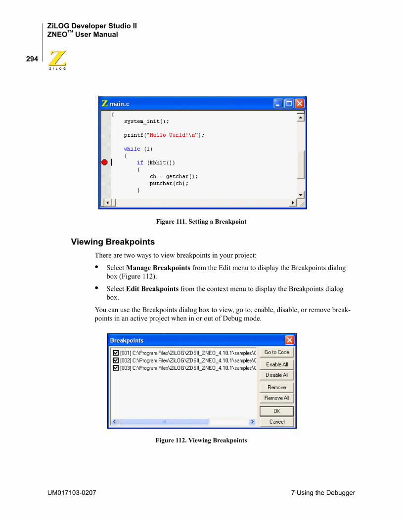
ZiLOG Developer Studio IIZNEO™ User Manual
294
Figure 111. Setting a Breakpoint
Viewing BreakpointsThere are two ways to view breakpoints in your project:
• Select Manage Breakpoints from the Edit menu to display the Breakpoints dialog box (Figure 112).
• Select Edit Breakpoints from the context menu to display the Breakpoints dialog box.
You can use the Breakpoints dialog box to view, go to, enable, disable, or remove break-points in an active project when in or out of Debug mode.
Figure 112. Viewing Breakpoints
UM017103-0207 7 Using the Debugger
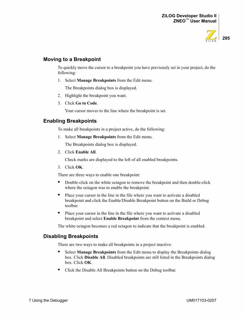
ZiLOG Developer Studio IIZNEO™ User Manual
295
Moving to a BreakpointTo quickly move the cursor to a breakpoint you have previously set in your project, do the following:
1. Select Manage Breakpoints from the Edit menu.
The Breakpoints dialog box is displayed.
2. Highlight the breakpoint you want.
3. Click Go to Code.
Your cursor moves to the line where the breakpoint is set.
Enabling BreakpointsTo make all breakpoints in a project active, do the following:
1. Select Manage Breakpoints from the Edit menu.
The Breakpoints dialog box is displayed.
2. Click Enable All.
Check marks are displayed to the left of all enabled breakpoints.
3. Click OK.
There are three ways to enable one breakpoint:
• Double-click on the white octagon to remove the breakpoint and then double-click where the octagon was to enable the breakpoint.
• Place your cursor in the line in the file where you want to activate a disabled breakpoint and click the Enable/Disable Breakpoint button on the Build or Debug toolbar.
• Place your cursor in the line in the file where you want to activate a disabled breakpoint and select Enable Breakpoint from the context menu.
The white octagon becomes a red octagon to indicate that the breakpoint is enabled.
Disabling BreakpointsThere are two ways to make all breakpoints in a project inactive:
• Select Manage Breakpoints from the Edit menu to display the Breakpoints dialog box. Click Disable All. Disabled breakpoints are still listed in the Breakpoints dialog box. Click OK.
• Click the Disable All Breakpoints button on the Debug toolbar.
7 Using the Debugger UM017103-0207
ZiLOG Developer Studio IIZNEO™ User Manual
296
There are two ways to disable one breakpoint:
• Place your cursor in the line in the file where you want to deactivate an active breakpoint and click the Enable/Disable Breakpoint button on the Build or Debug toolbar.
• Place your cursor in the line in the file where you want to deactivate an active breakpoint and select Disable Breakpoint from the context menu.
The red octagon becomes a white octagon to indicate that the breakpoint is disabled.
Removing BreakpointsThere are two ways to delete all breakpoints in a project:
• Select Manage Breakpoints from the Edit menu to display the Breakpoints dialog box. Click Remove All and then click OK. All breakpoints are removed from the Breakpoints dialog box and all project files.
• Click the Remove All Breakpoints button on the Build or Debug toolbar.
There are four ways to delete a single breakpoint:
• Double-click on the red octagon to remove the breakpoint.
• Select Manage Breakpoints from the Edit menu to display the Breakpoints dialog box. Click Remove and then click OK. The breakpoint is removed from the Breakpoints dialog box and the file.
• Place your cursor in the line in the file where there is a breakpoint and click the Insert/Remove Breakpoint button on the Build or Debug toolbar.
• Place your cursor in the line in the file where there is a breakpoint and select Remove Breakpoint from the context menu.
UM017103-0207 7 Using the Debugger
ZiLOG Developer Studio IIZNEO™ User Manual
297
Appendix A Running ZDS II from the Com-mand Line
You can run ZDS II from the command line. ZDS II generates a make file (project_Debug.mak or project_Release.mak, depending on the project configuration) every time you build or rebuild a project. For a project named test.zdsproj set up in the Debug configuration, ZDS II generates a make file named test_Debug.mak in the project directory. You can use this make file to run your project from the command line.
This section covers the following topics:
• “Building a Project from the Command Line” on page 297
• “Running the Compiler from the Command Line” on page 298
• “Running the Assembler from the Command Line” on page 298
• “Running the Linker from the Command Line” on page 298
• “Assembler Command Line Options” on page 299
• “Compiler Command Line Options” on page 301
• “Librarian Command Line Options” on page 304
• “Linker Command Line Options” on page 304
BUILDING A PROJECT FROM THE COMMAND LINETo build a project from the command line, use the following procedure:
1. Add the ZDS II bin directory (for example, C:\Program Files\ZiLOG\ZDSII_Z8Encore!_4.11.0\bin) to your path by setting the PATH environment variable.
The make utility is available in this directory.
2. Open the project using the IDE.
3. Export the make file for the project using the Export Makefile command in the Project menu.
4. Open a DOS window and change to the intermediate files directory.
5. Build the project using the make utility on the command line in a DOS window.
To build a project by compiling only the changed files, use the following command:make -f sampleproject_Debug.mak
To rebuild the entire project, use the following command:make rebuildall -f sampleproject_Debug.mak
Appendix A Running ZDS II from the Command Line UM017103-0207
ZiLOG Developer Studio IIZNEO™ User Manual
298
RUNNING THE COMPILER FROM THE COMMAND LINETo run the compiler from the command line:
1. Open the make file in a text editor.
2. Copy the options in the CFLAGS section.
3. In a Command Prompt window, type the path to the compiler, the options from the CFLAGS section (on a single line and without backslashes), and your C file. For example:
C:\PROGRA~1\ZiLOG\ZDSII_ZNEO_4.11.0\bin\eZ8cc -alias -asm -const:RAM -debug -define:_z8f64 -NOexpmac -NOfplib -intsrc -intrinsic -NOkeepasm -NOkeeplst -NOlist -NOlistinc -maxerrs:50 -NOmodsect -promote -quiet -NOstrict -NOwatch -optsize -localopt -localcse -localfold -localcopy -peephole -globalopt -NOglobalcse -NOglobalfold -NOglobalcopy -NOloopopt -NOsdiopt -NOjmpopt -stdinc:"..\include;C:\PROGRA~1\ZiLOG\ZDSII_ZNEO_4.11.0\include" -usrinc:"..\include" -cpu:z8f64 -bitfieldsize:24 -charsize:8 -doublesize:32 -floatsize:32 -intsize:24 -longsize:32 -shortsize:16 -asmsw:"-cpu:z8f64" test.c
NOTE: If you use DOS, use double quotation marks for the -stdinc and -usrinc commands for the C-Compiler. For example: -stdinc:"C:\ez8\include"
If you use cygwin, use single quotation marks on both sides of a pair of braces for the -stdinc and -usrinc commands for the C-Compiler. For example: -stdinc:'{C:\ez8\include}'
RUNNING THE ASSEMBLER FROM THE COMMAND LINETo run the assembler from the command line:
1. Open the make file in a text editor.
2. Copy the options in the AFLAGS section.
3. In a Command Prompt window, type the path to the assembler, the options from the AFLAGS section (on a single line and without backslashes), and your assembly file. For example:
C:\PROGRA~1\ZiLOG\ZDSII_ZNEO_4.11.0\bin\eZ8asm -debug -genobj -NOigcase -include:"..\include" -list -NOlistmac -name -pagelen:56 -pagewidth:80 -quiet -warn -NOzmasm -cpu:z8f64 test.asm
RUNNING THE LINKER FROM THE COMMAND LINETo run the linker from the command line:
1. Open the make file in a text editor.
UM017103-0207 Appendix A Running ZDS II from the Command Line
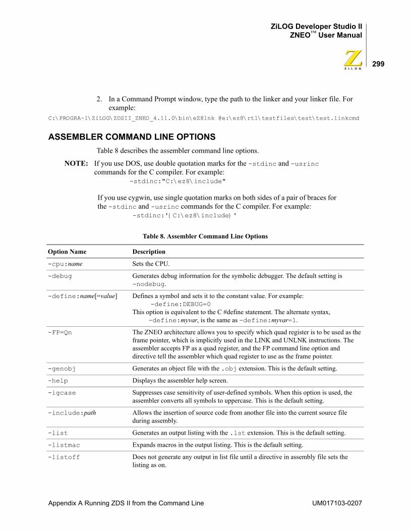
ZiLOG Developer Studio IIZNEO™ User Manual
299
2. In a Command Prompt window, type the path to the linker and your linker file. For example:
C:\PROGRA~1\ZiLOG\ZDSII_ZNEO_4.11.0\bin\eZ8lnk @e:\ez8\rtl\testfiles\test\test.linkcmd
ASSEMBLER COMMAND LINE OPTIONSTable 8 describes the assembler command line options.
NOTE: If you use DOS, use double quotation marks for the -stdinc and -usrinc commands for the C compiler. For example: -stdinc:"C:\ez8\include"
If you use cygwin, use single quotation marks on both sides of a pair of braces for the -stdinc and -usrinc commands for the C compiler. For example: -stdinc:'{C:\ez8\include}'
Table 8. Assembler Command Line Options
Option Name Description
-cpu:name Sets the CPU.
-debug Generates debug information for the symbolic debugger. The default setting is -nodebug.
-define:name[=value] Defines a symbol and sets it to the constant value. For example: -define:DEBUG=0This option is equivalent to the C #define statement. The alternate syntax, -define:myvar, is the same as -define:myvar=1.
-FP=Qn The ZNEO architecture allows you to specify which quad register is to be used as the frame pointer, which is implicitly used in the LINK and UNLNK instructions. The assembler accepts FP as a quad register, and the FP command line option and directive tell the assembler which quad register to use as the frame pointer.
-genobj Generates an object file with the .obj extension. This is the default setting.
-help Displays the assembler help screen.
-igcase Suppresses case sensitivity of user-defined symbols. When this option is used, the assembler converts all symbols to uppercase. This is the default setting.
-include:path Allows the insertion of source code from another file into the current source file during assembly.
-list Generates an output listing with the .lst extension. This is the default setting.
-listmac Expands macros in the output listing. This is the default setting.
-listoff Does not generate any output in list file until a directive in assembly file sets the listing as on.
Appendix A Running ZDS II from the Command Line UM017103-0207
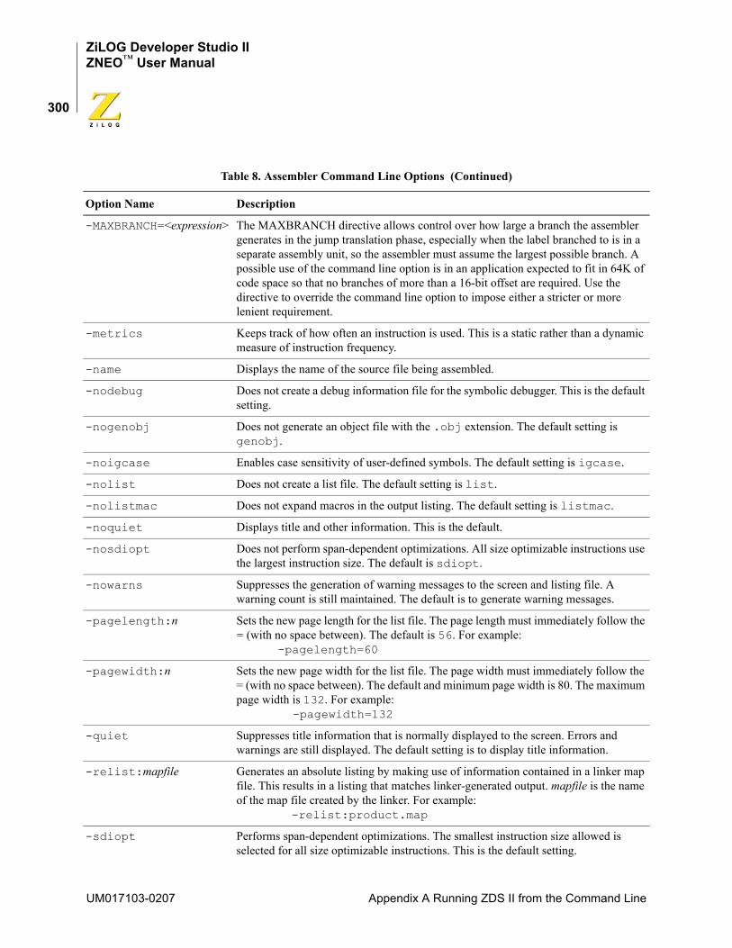
ZiLOG Developer Studio IIZNEO™ User Manual
300
-MAXBRANCH=<expression> The MAXBRANCH directive allows control over how large a branch the assembler generates in the jump translation phase, especially when the label branched to is in a separate assembly unit, so the assembler must assume the largest possible branch. A possible use of the command line option is in an application expected to fit in 64K of code space so that no branches of more than a 16-bit offset are required. Use the directive to override the command line option to impose either a stricter or more lenient requirement.
-metrics Keeps track of how often an instruction is used. This is a static rather than a dynamic measure of instruction frequency.
-name Displays the name of the source file being assembled.
-nodebug Does not create a debug information file for the symbolic debugger. This is the default setting.
-nogenobj Does not generate an object file with the .obj extension. The default setting is genobj.
-noigcase Enables case sensitivity of user-defined symbols. The default setting is igcase.
-nolist Does not create a list file. The default setting is list.
-nolistmac Does not expand macros in the output listing. The default setting is listmac.
-noquiet Displays title and other information. This is the default.
-nosdiopt Does not perform span-dependent optimizations. All size optimizable instructions use the largest instruction size. The default is sdiopt.
-nowarns Suppresses the generation of warning messages to the screen and listing file. A warning count is still maintained. The default is to generate warning messages.
-pagelength:n Sets the new page length for the list file. The page length must immediately follow the = (with no space between). The default is 56. For example: -pagelength=60
-pagewidth:n Sets the new page width for the list file. The page width must immediately follow the = (with no space between). The default and minimum page width is 80. The maximum page width is 132. For example: -pagewidth=132
-quiet Suppresses title information that is normally displayed to the screen. Errors and warnings are still displayed. The default setting is to display title information.
-relist:mapfile Generates an absolute listing by making use of information contained in a linker map file. This results in a listing that matches linker-generated output. mapfile is the name of the map file created by the linker. For example: -relist:product.map
-sdiopt Performs span-dependent optimizations. The smallest instruction size allowed is selected for all size optimizable instructions. This is the default setting.
Table 8. Assembler Command Line Options (Continued)
Option Name Description
UM017103-0207 Appendix A Running ZDS II from the Command Line
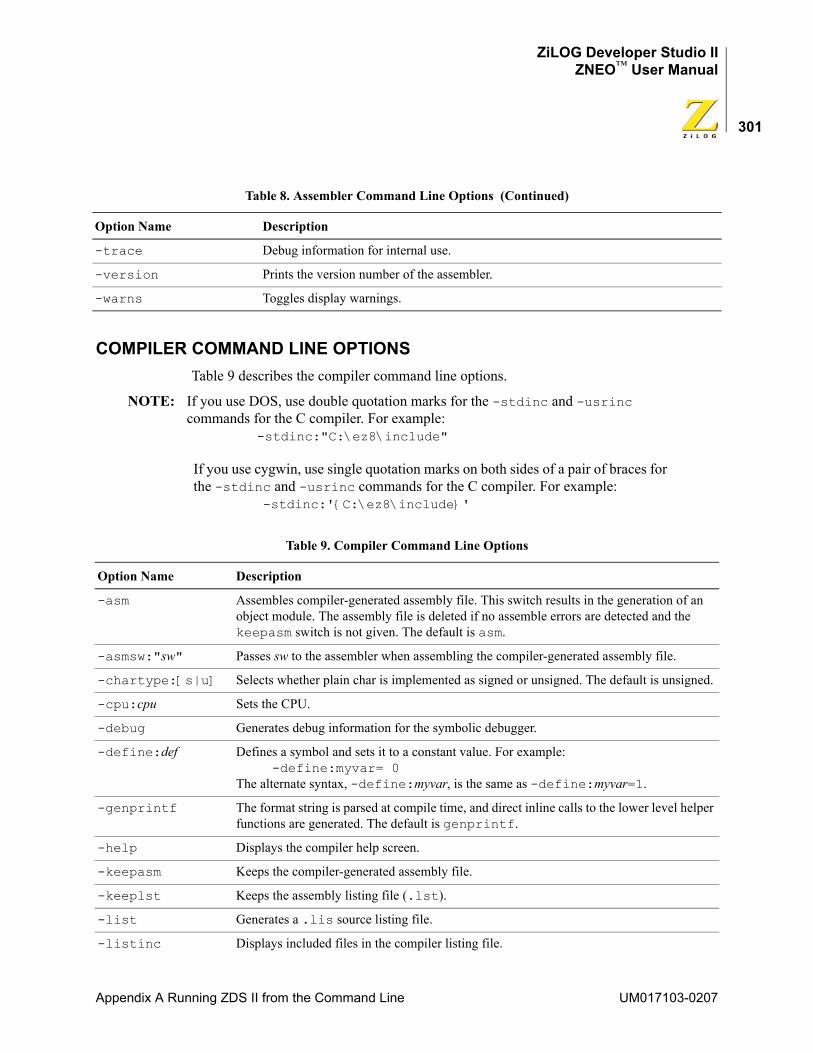
ZiLOG Developer Studio IIZNEO™ User Manual
301
COMPILER COMMAND LINE OPTIONSTable 9 describes the compiler command line options.
NOTE: If you use DOS, use double quotation marks for the -stdinc and -usrinc commands for the C compiler. For example: -stdinc:"C:\ez8\include"
If you use cygwin, use single quotation marks on both sides of a pair of braces for the -stdinc and -usrinc commands for the C compiler. For example: -stdinc:'{C:\ez8\include}'
-trace Debug information for internal use.
-version Prints the version number of the assembler.
-warns Toggles display warnings.
Table 9. Compiler Command Line Options
Option Name Description
-asm Assembles compiler-generated assembly file. This switch results in the generation of an object module. The assembly file is deleted if no assemble errors are detected and the keepasm switch is not given. The default is asm.
-asmsw:"sw" Passes sw to the assembler when assembling the compiler-generated assembly file.
-chartype:[s|u] Selects whether plain char is implemented as signed or unsigned. The default is unsigned.
-cpu:cpu Sets the CPU.
-debug Generates debug information for the symbolic debugger.
-define:def Defines a symbol and sets it to a constant value. For example: -define:myvar= 0The alternate syntax, -define:myvar, is the same as -define:myvar=1.
-genprintf The format string is parsed at compile time, and direct inline calls to the lower level helper functions are generated. The default is genprintf.
-help Displays the compiler help screen.
-keepasm Keeps the compiler-generated assembly file.
-keeplst Keeps the assembly listing file (.lst).
-list Generates a .lis source listing file.
-listinc Displays included files in the compiler listing file.
Table 8. Assembler Command Line Options (Continued)
Option Name Description
Appendix A Running ZDS II from the Command Line UM017103-0207
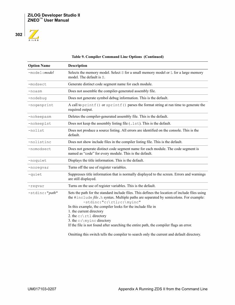
ZiLOG Developer Studio IIZNEO™ User Manual
302
-model:model Selects the memory model. Select S for a small memory model or L for a large memory model. The default is S.
-modsect Generate distinct code segment name for each module.
-noasm Does not assemble the compiler-generated assembly file.
-nodebug Does not generate symbol debug information. This is the default.
-nogenprint A call to printf() or sprintf() parses the format string at run time to generate the required output.
-nokeepasm Deletes the compiler-generated assembly file. This is the default.
-nokeeplst Does not keep the assembly listing file (.lst). This is the default.
-nolist Does not produce a source listing. All errors are identified on the console. This is the default.
-nolistinc Does not show include files in the compiler listing file. This is the default.
-nomodsect Does not generate distinct code segment name for each module. The code segment is named as “code” for every module. This is the default.
-noquiet Displays the title information. This is the default.
-noregvar Turns off the use of register variables.
-quiet Suppresses title information that is normally displayed to the screen. Errors and warnings are still displayed.
-regvar Turns on the use of register variables. This is the default.
-stdinc:"path" Sets the path for the standard include files. This defines the location of include files using the #include file.h syntax. Multiple paths are separated by semicolons. For example: -stdinc:"c:\rtl;c:\myinc"In this example, the compiler looks for the include file in1. the current directory2. the c:\rtl directory3. the c:\myinc directoryIf the file is not found after searching the entire path, the compiler flags an error.
Omitting this switch tells the compiler to search only the current and default directory.
Table 9. Compiler Command Line Options (Continued)
Option Name Description
UM017103-0207 Appendix A Running ZDS II from the Command Line
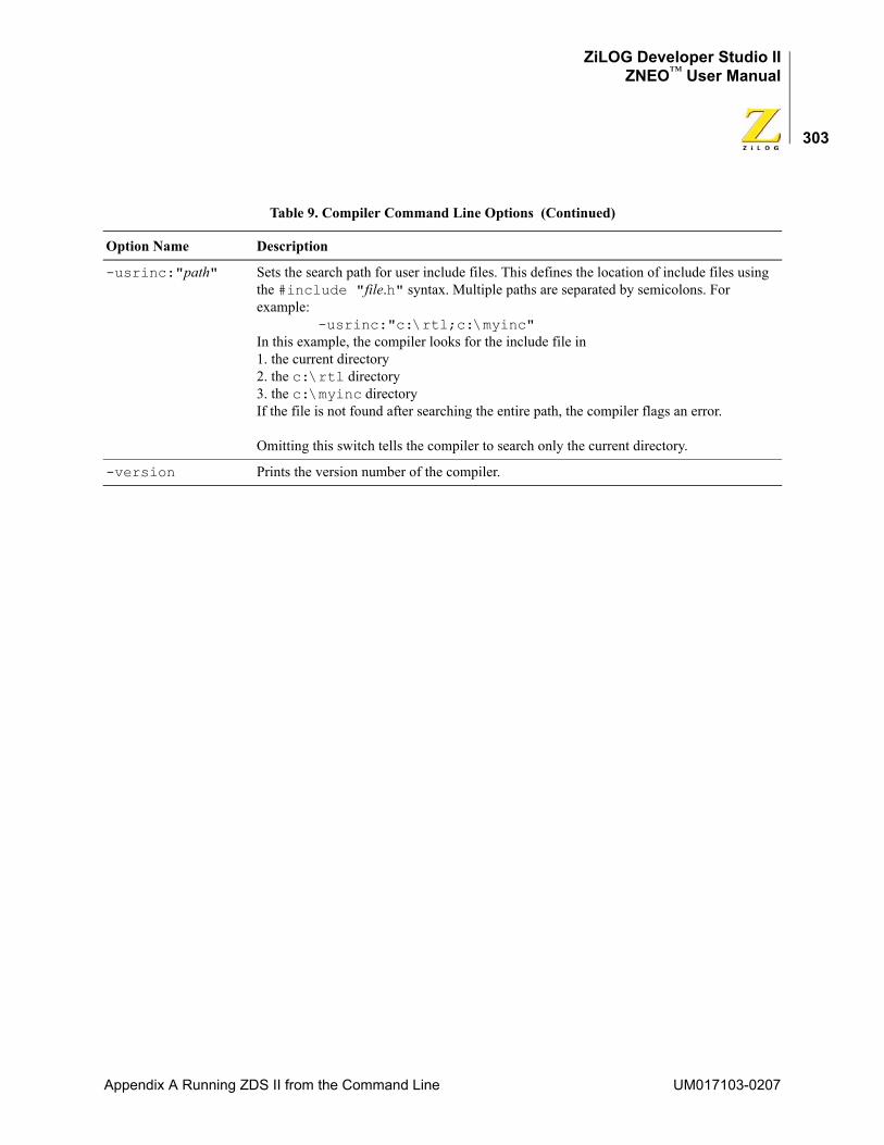
ZiLOG Developer Studio IIZNEO™ User Manual
303
-usrinc:"path" Sets the search path for user include files. This defines the location of include files using the #include "file.h" syntax. Multiple paths are separated by semicolons. For example: -usrinc:"c:\rtl;c:\myinc"In this example, the compiler looks for the include file in1. the current directory2. the c:\rtl directory3. the c:\myinc directoryIf the file is not found after searching the entire path, the compiler flags an error.
Omitting this switch tells the compiler to search only the current directory.
-version Prints the version number of the compiler.
Table 9. Compiler Command Line Options (Continued)
Option Name Description
Appendix A Running ZDS II from the Command Line UM017103-0207
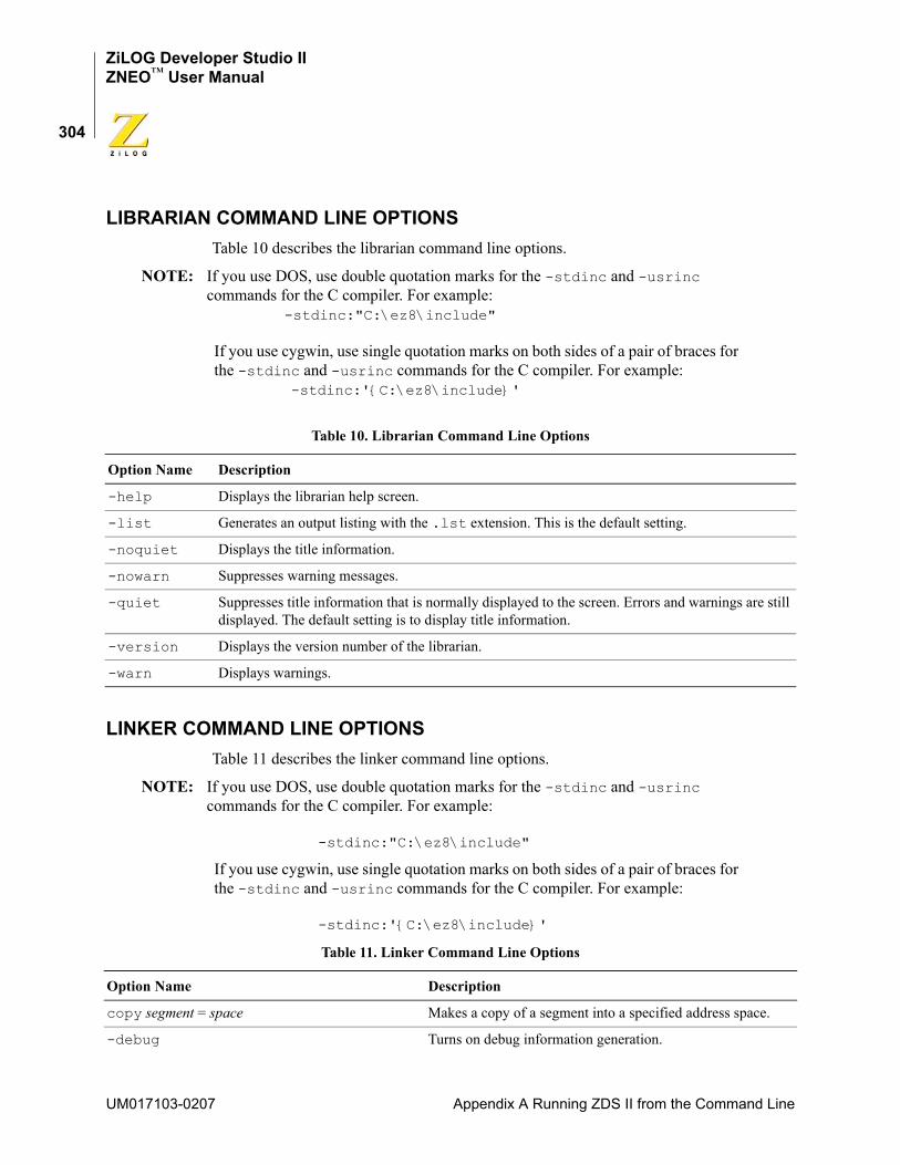
ZiLOG Developer Studio IIZNEO™ User Manual
304
LIBRARIAN COMMAND LINE OPTIONSTable 10 describes the librarian command line options.
NOTE: If you use DOS, use double quotation marks for the -stdinc and -usrinc commands for the C compiler. For example: -stdinc:"C:\ez8\include"
If you use cygwin, use single quotation marks on both sides of a pair of braces for the -stdinc and -usrinc commands for the C compiler. For example: -stdinc:'{C:\ez8\include}'
LINKER COMMAND LINE OPTIONSTable 11 describes the linker command line options.
NOTE: If you use DOS, use double quotation marks for the -stdinc and -usrinc commands for the C compiler. For example:
-stdinc:"C:\ez8\include"
If you use cygwin, use single quotation marks on both sides of a pair of braces for the -stdinc and -usrinc commands for the C compiler. For example:
-stdinc:'{C:\ez8\include}'
Table 10. Librarian Command Line Options
Option Name Description
-help Displays the librarian help screen.
-list Generates an output listing with the .lst extension. This is the default setting.
-noquiet Displays the title information.
-nowarn Suppresses warning messages.
-quiet Suppresses title information that is normally displayed to the screen. Errors and warnings are still displayed. The default setting is to display title information.
-version Displays the version number of the librarian.
-warn Displays warnings.
Table 11. Linker Command Line Options
Option Name Description
copy segment = space Makes a copy of a segment into a specified address space.
-debug Turns on debug information generation.
UM017103-0207 Appendix A Running ZDS II from the Command Line
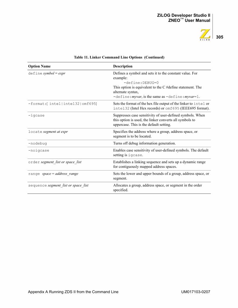
ZiLOG Developer Studio IIZNEO™ User Manual
305
define symbol = expr Defines a symbol and sets it to the constant value. For example: -define:DEBUG=0This option is equivalent to the C #define statement. The alternate syntax, -define:myvar, is the same as -define:myvar=1.
-format:[intel|intel32|omf695] Sets the format of the hex file output of the linker to intel or intel32 (Intel Hex records) or omf695 (IEEE695 format).
-igcase Suppresses case sensitivity of user-defined symbols. When this option is used, the linker converts all symbols to uppercase. This is the default setting.
locate segment at expr Specifies the address where a group, address space, or segment is to be located.
-nodebug Turns off debug information generation.
-noigcase Enables case sensitivity of user-defined symbols. The default setting is igcase.
order segment_list or space_list Establishes a linking sequence and sets up a dynamic range for contiguously mapped address spaces.
range space = address_range Sets the lower and upper bounds of a group, address space, or segment.
sequence segment_list or space_list Allocates a group, address space, or segment in the order specified.
Table 11. Linker Command Line Options (Continued)
Option Name Description
Appendix A Running ZDS II from the Command Line UM017103-0207
ZiLOG Developer Studio IIZNEO™ User Manual
306
UM017103-0207 Appendix A Running ZDS II from the Command Line
ZiLOG Developer Studio IIZNEO™ User Manual
307
Appendix B Using the Command ProcessorThe Command Processor allows you to use commands or script files to automate the exe-cution of a significant portion of the functionality of the integrated development environ-ment (IDE). This section covers the following topics:
• “Sample Command Script File” on page 311
• “Supported Script File Commands” on page 312
• “Running the Flash Loader from the Command Processor” on page 333
You can run commands in one of the following ways:
• Using the Command Processor toolbar in the IDE to run a single command.
Commands entered into the Command Processor toolbar are executed after you press the Enter (or Return) key or click the Run Command button. The toolbar is described in “Command Processor Toolbar” on page 21.
• Using the batch command to run a command script file from the Command Processor toolbar in the IDE.
For example: batch "c:\path\to\command\file\runall.cmd" batch "commands.txt"
• Passing a command script file to the IDE when it is started.
You must precede the script file with an at symbol (@) when passing the path and name of the command script file to the IDE on the command line. For example:
zds2ide @c:\path\to\command\file\runall.cmd zds2ide @commands.txt
Processed commands are echoed, and associated results are displayed in the Command Output window in the IDE and, if logging is enabled (see “log” on page 321), in the log file as well.
Commands are not case sensitive.
In directory or path-based parameters, you can use \, \\, or / as separators as long as you use the same separator throughout a single parameter. For example, the following exam-ples are legal:cd "..\path\to\change\to" cd "..\\path\\to\\change\\to" cd "../path/to/change/to"
The following examples are illegal:cd "..\path/to\change/to" cd "..\\path\to\change\to"
Appendix B Using the Command Processor UM017103-0207
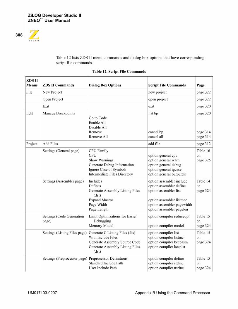
ZiLOG Developer Studio IIZNEO™ User Manual
308
Table 12 lists ZDS II menu commands and dialog box options that have corresponding script file commands.
Table 12. Script File Commands
ZDS II Menus ZDS II Commands Dialog Box Options Script File Commands Page
File New Project new project page 322
Open Project open project page 322
Exit exit page 320
Edit Manage BreakpointsGo to CodeEnable AllDisable AllRemoveRemove All
list bp
cancel bpcancel all
page 320
page 314page 314
Project Add Files add file page 312
Settings (General page) CPU FamilyCPUShow WarningsGenerate Debug InformationIgnore Case of SymbolsIntermediate Files Directory
option general cpuoption general warnoption general debugoption general igcaseoption general outputdir
Table 16 on page 325
Settings (Assembler page) IncludesDefinesGenerate Assembly Listing Files (.lst)Expand MacrosPage WidthPage Length
option assembler includeoption assembler defineoption assembler list
option assembler listmacoption assembler pagewidthoption assembler pagelen
Table 14 on page 324
Settings (Code Generation page)
Limit Optimizations for Easier DebuggingMemory Model
option compiler reduceopt
option compiler model
Table 15 on page 324
Settings (Listing Files page) Generate C Listing Files (.lis)With Include FilesGenerate Assembly Source Code Generate Assembly Listing Files (.lst)
option compiler listoption compiler listincoption compiler keepasmoption compiler keeplst
Table 15 on page 324
Settings (Preprocessor page) Preprocessor DefinitionsStandard Include PathUser Include Path
option compiler defineoption compiler stdincoption compiler usrinc
Table 15 on page 324
UM017103-0207 Appendix B Using the Command Processor
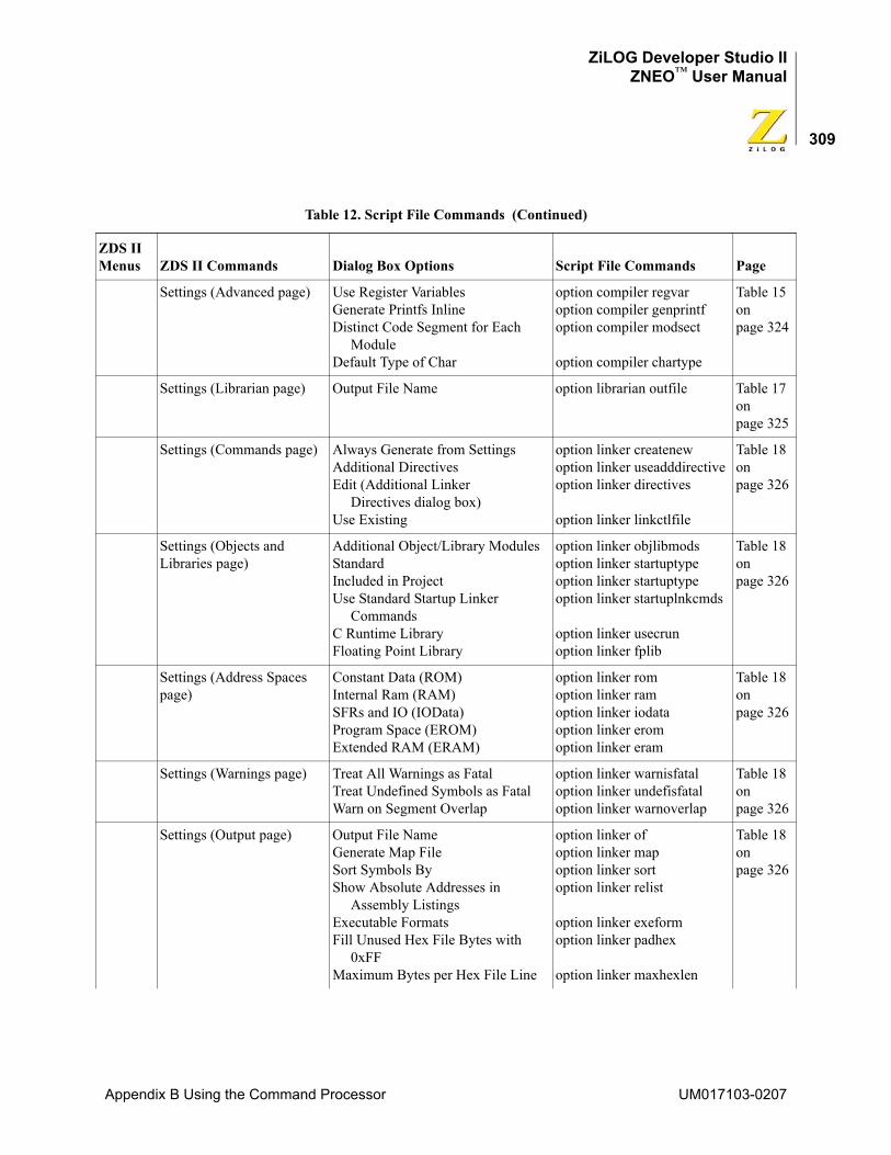
ZiLOG Developer Studio IIZNEO™ User Manual
309
Settings (Advanced page) Use Register VariablesGenerate Printfs InlineDistinct Code Segment for Each ModuleDefault Type of Char
option compiler regvaroption compiler genprintfoption compiler modsect
option compiler chartype
Table 15 on page 324
Settings (Librarian page) Output File Name option librarian outfile Table 17 on page 325
Settings (Commands page) Always Generate from SettingsAdditional DirectivesEdit (Additional Linker Directives dialog box)Use Existing
option linker createnewoption linker useadddirectiveoption linker directives
option linker linkctlfile
Table 18 on page 326
Settings (Objects and Libraries page)
Additional Object/Library ModulesStandardIncluded in ProjectUse Standard Startup Linker CommandsC Runtime LibraryFloating Point Library
option linker objlibmodsoption linker startuptypeoption linker startuptypeoption linker startuplnkcmds
option linker usecrunoption linker fplib
Table 18 on page 326
Settings (Address Spaces page)
Constant Data (ROM)Internal Ram (RAM)SFRs and IO (IOData)Program Space (EROM)Extended RAM (ERAM)
option linker romoption linker ramoption linker iodataoption linker eromoption linker eram
Table 18 on page 326
Settings (Warnings page) Treat All Warnings as FatalTreat Undefined Symbols as FatalWarn on Segment Overlap
option linker warnisfataloption linker undefisfataloption linker warnoverlap
Table 18 on page 326
Settings (Output page) Output File NameGenerate Map FileSort Symbols ByShow Absolute Addresses in Assembly ListingsExecutable FormatsFill Unused Hex File Bytes with 0xFFMaximum Bytes per Hex File Line
option linker ofoption linker mapoption linker sortoption linker relist
option linker exeformoption linker padhex
option linker maxhexlen
Table 18 on page 326
Table 12. Script File Commands (Continued)
ZDS II Menus ZDS II Commands Dialog Box Options Script File Commands Page
Appendix B Using the Command Processor UM017103-0207
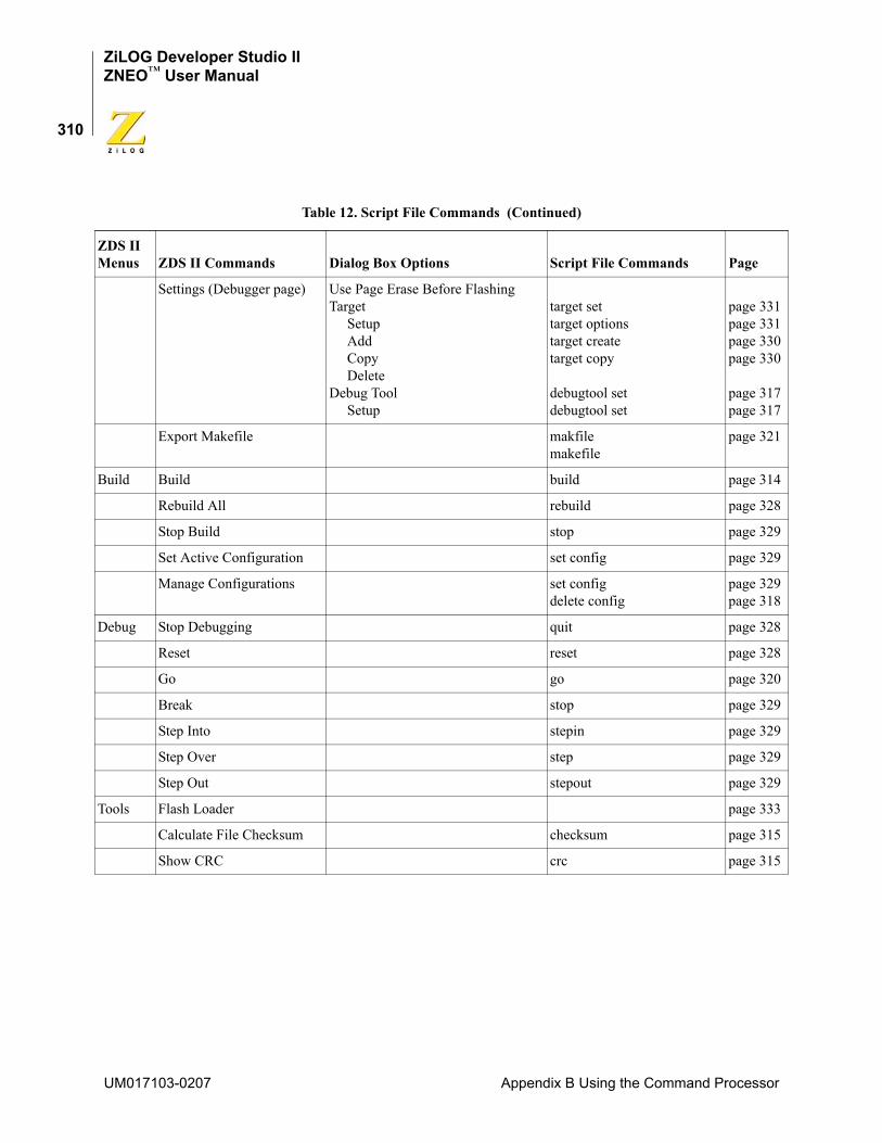
ZiLOG Developer Studio IIZNEO™ User Manual
310
Settings (Debugger page) Use Page Erase Before FlashingTarget Setup Add Copy DeleteDebug Tool Setup
target settarget optionstarget createtarget copy
debugtool setdebugtool set
page 331page 331page 330page 330
page 317page 317
Export Makefile makfilemakefile
page 321
Build Build build page 314
Rebuild All rebuild page 328
Stop Build stop page 329
Set Active Configuration set config page 329
Manage Configurations set configdelete config
page 329page 318
Debug Stop Debugging quit page 328
Reset reset page 328
Go go page 320
Break stop page 329
Step Into stepin page 329
Step Over step page 329
Step Out stepout page 329
Tools Flash Loader page 333
Calculate File Checksum checksum page 315
Show CRC crc page 315
Table 12. Script File Commands (Continued)
ZDS II Menus ZDS II Commands Dialog Box Options Script File Commands Page
UM017103-0207 Appendix B Using the Command Processor
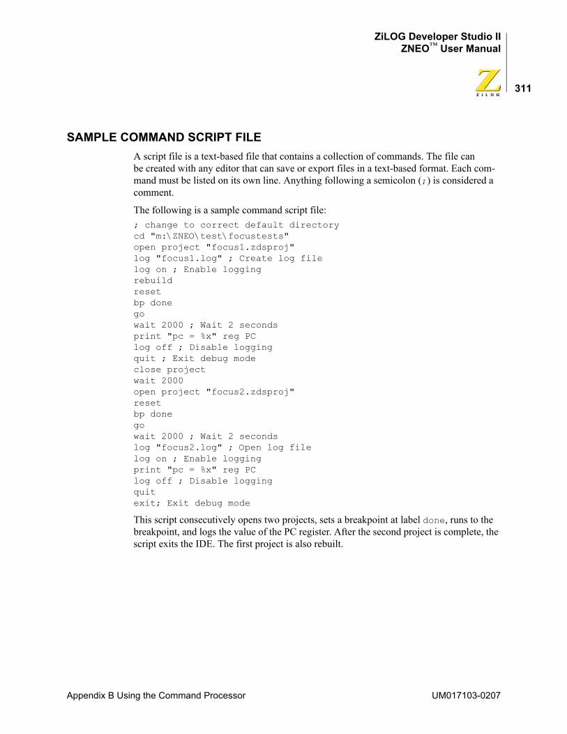
ZiLOG Developer Studio IIZNEO™ User Manual
311
SAMPLE COMMAND SCRIPT FILEA script file is a text-based file that contains a collection of commands. The file can be created with any editor that can save or export files in a text-based format. Each com-mand must be listed on its own line. Anything following a semicolon (;) is considered a comment.
The following is a sample command script file:; change to correct default directory cd "m:\ZNEO\test\focustests" open project "focus1.zdsproj" log "focus1.log" ; Create log file log on ; Enable logging rebuild reset bp done go wait 2000 ; Wait 2 seconds print "pc = %x" reg PC log off ; Disable logging quit ; Exit debug mode close project wait 2000 open project "focus2.zdsproj" reset bp done go wait 2000 ; Wait 2 seconds log "focus2.log" ; Open log file log on ; Enable logging print "pc = %x" reg PC log off ; Disable logging quit exit; Exit debug mode
This script consecutively opens two projects, sets a breakpoint at label done, runs to the breakpoint, and logs the value of the PC register. After the second project is complete, the script exits the IDE. The first project is also rebuilt.
Appendix B Using the Command Processor UM017103-0207
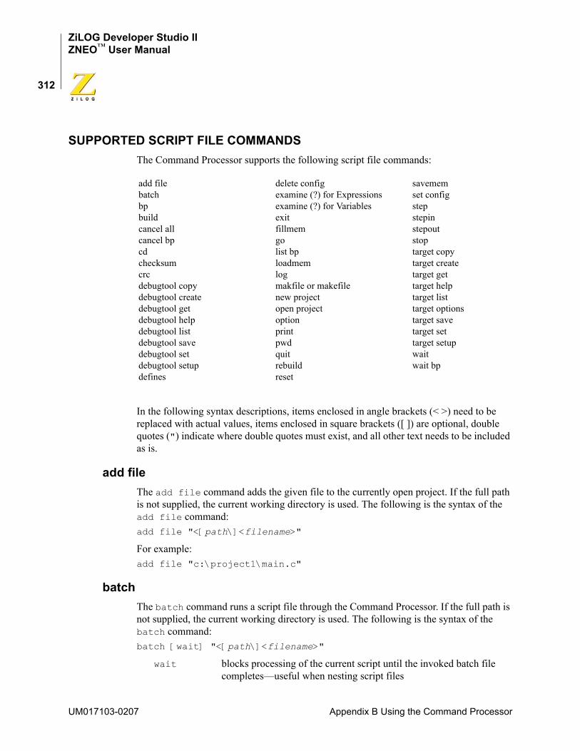
ZiLOG Developer Studio IIZNEO™ User Manual
312
SUPPORTED SCRIPT FILE COMMANDSThe Command Processor supports the following script file commands:
In the following syntax descriptions, items enclosed in angle brackets (< >) need to be replaced with actual values, items enclosed in square brackets ([ ]) are optional, double quotes (") indicate where double quotes must exist, and all other text needs to be included as is.
add fileThe add file command adds the given file to the currently open project. If the full path is not supplied, the current working directory is used. The following is the syntax of the add file command:add file "<[path\]<filename>"
For example:add file "c:\project1\main.c"
batchThe batch command runs a script file through the Command Processor. If the full path is not supplied, the current working directory is used. The following is the syntax of the batch command:batch [wait] "<[path\]<filename>"
wait blocks processing of the current script until the invoked batch file completes—useful when nesting script files
add filebatchbpbuildcancel allcancel bpcdchecksumcrcdebugtool copydebugtool createdebugtool getdebugtool helpdebugtool listdebugtool savedebugtool setdebugtool setupdefines
delete configexamine (?) for Expressionsexamine (?) for Variablesexitfillmemgolist bploadmemlogmakfile or makefilenew projectopen projectoptionprintpwdquitrebuildreset
savememset configstepstepinstepoutstoptarget copytarget createtarget gettarget helptarget listtarget optionstarget savetarget settarget setupwaitwait bp
UM017103-0207 Appendix B Using the Command Processor
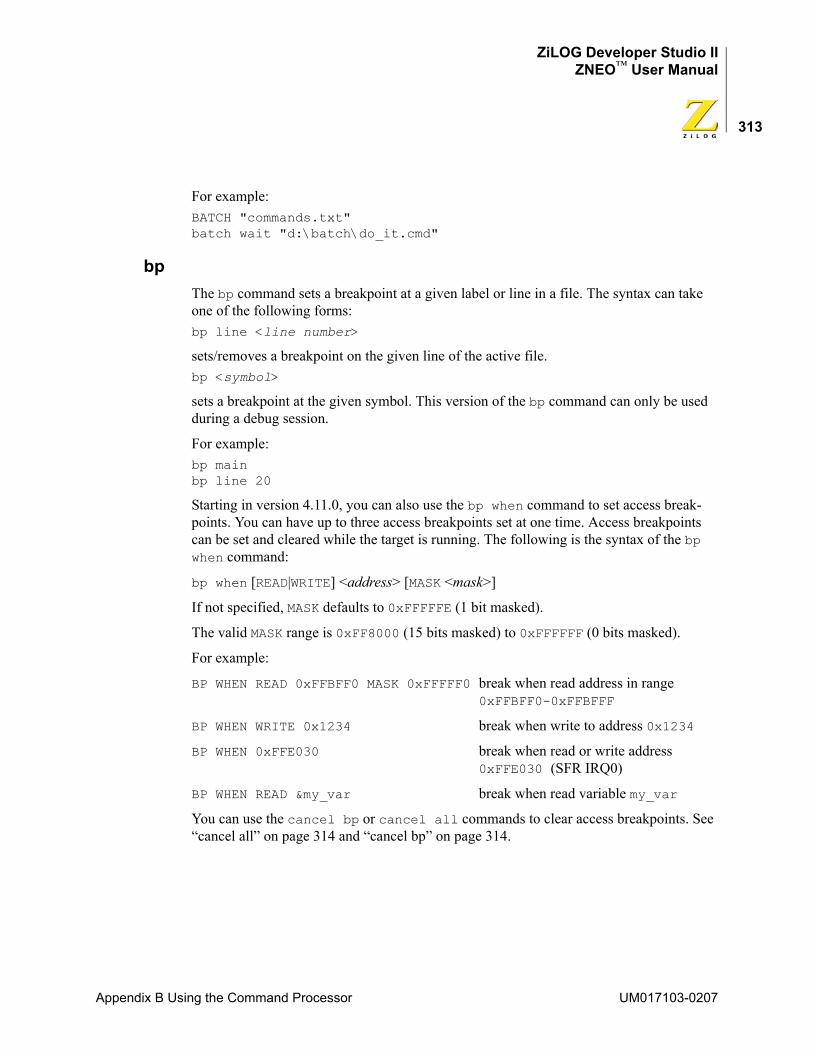
ZiLOG Developer Studio IIZNEO™ User Manual
313
For example:BATCH "commands.txt" batch wait "d:\batch\do_it.cmd"
bpThe bp command sets a breakpoint at a given label or line in a file. The syntax can take one of the following forms:bp line <line number>
sets/removes a breakpoint on the given line of the active file.bp <symbol>
sets a breakpoint at the given symbol. This version of the bp command can only be used during a debug session.
For example:bp main bp line 20
Starting in version 4.11.0, you can also use the bp when command to set access break-points. You can have up to three access breakpoints set at one time. Access breakpoints can be set and cleared while the target is running. The following is the syntax of the bp when command:
bp when [READ|WRITE] <address> [MASK <mask>]
If not specified, MASK defaults to 0xFFFFFE (1 bit masked).
The valid MASK range is 0xFF8000 (15 bits masked) to 0xFFFFFF (0 bits masked).
For example:
BP WHEN READ 0xFFBFF0 MASK 0xFFFFF0 break when read address in range 0xFFBFF0-0xFFBFFF
BP WHEN WRITE 0x1234 break when write to address 0x1234
BP WHEN 0xFFE030 break when read or write address 0xFFE030 (SFR IRQ0)
BP WHEN READ &my_var break when read variable my_var
You can use the cancel bp or cancel all commands to clear access breakpoints. See “cancel all” on page 314 and “cancel bp” on page 314.
Appendix B Using the Command Processor UM017103-0207
ZiLOG Developer Studio IIZNEO™ User Manual
314
buildThe build command builds the currently open project. This command blocks the execu-tion of other commands until the build process is complete. The following is the syntax of the build command:build
cancel allThe cancel all command clears all breakpoints in the currently loaded project. The fol-lowing is the syntax of the cancel all command:cancel all
Starting in version 4.11.0, you can also use the cancel all command to clear all break-points, including access breakpoints. For example:cancel all
To clear a specified breakpoint, see “cancel bp” on page 314. To set access breakpoints, see “bp” on page 313.
cancel bpThe cancel bp command clears the breakpoint at the bp list index. Use the list bp command to retrieve the index of a particular breakpoint. The following is the syntax of the cancel bp command:cancel bp <index>
For example:cancel bp 3
Starting in version 4.11.0, you can also use the cancel bp when command to clear an access breakpoint set at a specified address. The following is the syntax of the cancel bp when command:cancel bp when <address>
To clear all access breakpoints, see “cancel all” on page 314. To set access breakpoints, see “bp” on page 313.
cdThe cd command changes the working directory to dir. The following is the syntax of the cd command:cd "<dir>"
For example:cd "c:\temp" cd "../another_dir"
UM017103-0207 Appendix B Using the Command Processor
ZiLOG Developer Studio IIZNEO™ User Manual
315
checksumThe checksum command calculates the checksum of a hex file. The following is the syn-tax of the checksum command:checksum "<filename>"
For example, if you use the following command:checksum "ledblink.hex"
The file checksum for the example is:0xCEA3
crcThe CRC command performs a cyclic redundancy check (CRC). The syntax can take one of two forms:• crc
calculates the CRC for the whole Flash memory.• crc STARTADDRESS="<address>" ENDADDRESS="<endaddress>"
calculates the CRC for 4K-increment blocks. STARTADDRESS must be on a 4K boundary; if the address is not on a 4K boundary, ZDS II produces an error message. ENDADDRESS must be a 4K increment; if the end address is not a 4K increment, it is rounded up to a 4K increment.
For example:crc STARTADDRESS="1000" ENDADDRESS="1FFF"
debugtool copyThe debugtool copy command creates a copy of an existing debug tool with the given new name. The syntax can take one of two forms:• debugtool copy NAME="<new debug tool name>"
creates a copy of the active debug tool named the value given for NAME.
• debugtool copy NAME="<new debug tool name>" SOURCE="<existing debug tool name>"
creates a copy of the SOURCE debug tool named the value given for NAME.
For example:debugtool copy NAME="Sim3" SOURCE="Z16F2811AL"
Appendix B Using the Command Processor UM017103-0207
ZiLOG Developer Studio IIZNEO™ User Manual
316
debugtool createThe debugtool create command creates a new debug tool with the given name and using the given communication type: usb, tcpip, ethernet, or simulator. The fol-lowing is the syntax of the debugtool create command:debugtool create NAME="<debug tool name>" COMMTYPE="<comm type>"
For example:debugtool create NAME="emulator2" COMMTYPE="ethernet"
debugtool getThe debugtool get command displays the current value for the given data item for the active debug tool. Use the debugtool setup command to view available data items and current values. The following is the syntax of the debugtool get command:debugtool get "<data item>"
For example:debugtool get "ipAddress"
debugtool helpThe debugtool help command displays all debugtool commands. The following is the syntax of the debugtool help command:debugtool help
debugtool listThe debugtool list command lists all available debug tools. The syntax can take one of two forms:• debugtool list
displays the names of all available debug tools.• debugtool list COMMTYPE="<type>"
displays the names of all available debug tools using the given communications type: usb, tcpip, ethernet, or simulator.
For example:debugtool list COMMTYPE="ethernet"
debugtool saveThe debugtool save command saves a debug tool configuration to disk. The syntax can take one of two forms:• debugtool save
saves the active debug tool.
UM017103-0207 Appendix B Using the Command Processor
ZiLOG Developer Studio IIZNEO™ User Manual
317
• debugtool save NAME ="<Debug Tool Name>"
saves the given debug tool.
For example:debugtool save NAME="USBSmartCable"
debugtool setThe debugtool set command sets the given data item to the given data value for the active debug tool or activates a particular debug tool. The syntax can take one of two forms:• debugtool set "<data item>" "<new value>"
sets data item to new value for the active debug tool. Use debugtool setup to view available data items and current values.
For example:debugtool set "ipAddress" "123.456.7.89"
• debugtool set "<debug tool name>"
activates the debug tool with the given name. Use debugtool list to view available debug tools.
debugtool setupThe debugtool setup command displays the current configuration of the active debug tool. The following is the syntax of the debugtool setup command:debugtool setup
definesThe defines command provides a mechanism to add to, remove from, or replace define strings in the compiler preprocessor defines and assembler defines options. This command provides a more flexible method to modify the defines options than the option com-mand, which requires that the entire defines string be set with each use. Each defines parameter is a string containing a single define symbol, such as "TRACE" or "_SIMULATE=1". The defines command can take one of three forms:• defines <compiler|assembler> add "<new define>"
adds the given define to the compiler or assembler defines, as indicated by the first parameter.
• defines <compiler|assembler> replace "<new define>" "<old define>"
replaces <old define> with <new define> for the compiler or assembler defines, as indicated by the first parameter. If <old define> is not found, no change is made.
Appendix B Using the Command Processor UM017103-0207
ZiLOG Developer Studio IIZNEO™ User Manual
318
• defines <compiler|assembler> remove "<define to be removed>"
removes the given define from the compiler or assembler defines, as indicated by the first parameter.
For example:defines compiler add "_TRACE"defines assembler add "_TRACE=1"defines assembler replace "_TRACE" "_NOTRACE"defines assembler replace "_TRACE=1" "_TRACE=0"defines compiler remove "_NOTRACE"
delete configThe delete config command deletes the given existing project build configuration. The following is the syntax of the delete config command:delete config "<config_name>"
If <config_name> is active, the first remaining build configuration, if any, is made active. If <config_name> does not exist, no action is taken.
For example:delete config "MyDebug"
examine (?) for ExpressionsThe examine command evaluates the given expression and displays the result. It accepts any legal expression made up of constants, program variables, and C operators. The syn-tax takes the following form:? [<data_type>] [<radix>] <expr> [:<count>]
<data_type> can consist of one of the following types:
short int[eger] long ascii asciz
<radix> can consist of one of the following types:
dec[imal] hex[adecimal] oct[al] bin[ary]
Omitting a <data_type> or <radix> results in using the $data_type or $radix pseudo-variable, respectively.
[:<count>] represents the number of items to display.
UM017103-0207 Appendix B Using the Command Processor
ZiLOG Developer Studio IIZNEO™ User Manual
319
The following are examples:? x
shows the value of x using $data_type and $radix.? ascii STR
shows the ASCII string representation of STR.? 0x1000
shows the value of 0x1000 in the $data_type and $radix.? *0x1000
shows the byte at address 0x1000.? *0x1000 :25
shows 25 bytes at address 0x1000.? L0
shows the value of register D0:0 using $data_type and $radix.? asciz D0:0
shows the null-terminated string pointed to by the contents of register D0:0.
examine (?) for VariablesThe examine command displays the values of variables. This command works for values of any type, including arrays and structures. The following is the syntax:
? <expression>
The following are examples:
To see the value of z, enter?z
To see the nth value of array x, enter? x[n]
To see all values of array x, enter?x
To see the nth through the n+5th values of array x, enter?x[n]:5
If x is an array of pointers to strings, enter? asciz *x[n]
NOTE: When displaying a structure's value, the examine command also displays the names of each of the structure's elements.
Appendix B Using the Command Processor UM017103-0207
ZiLOG Developer Studio IIZNEO™ User Manual
320
exitThe exit command exits the IDE. The following is the syntax of the exit command:exit
fillmemThe fillmem command fills a block of a specified memory space with the specified value. The functionality is similar to the Fill Memory command available from the context menu in the Memory window (see “Fill Memory” on page 286). The following is the syn-tax of the fillmem command:
fillmem SPACE="<displayed spacename>" FILLVALUE="<hexcadecimal value>"[STARTADDRESS="<hexadecimal address>"] [ENDADDRESS="<hexadecimal address>"]
If STARTADDRESS and ENDADDRESS are not specified, all the memory contents of a spec-ified space are filled.
For example:fillmem SPACE="ROM" VALUE="AA"fillmem SPACE="ROM" VALUE="AA" STARTADDRESS="1000" ENDADDRESS="2FFF"
goThe go command executes the program code from the current program counter until a breakpoint or, optionally, a symbol is encountered. This command starts a debug session if one has not been started. The go command can take one of the following forms:• go
resumes execution from the current location.
• go <symbol>
resumes execution at the function identified by <symbol>. This version of the go command can only be used during a debug session.
The following are examples:gogo myfunc
list bpThe list bp command displays a list of all of the current breakpoints of the active file. The following is the syntax of the list bp command:list bp
loadmemThe loadmem command loads the data of an Intel hex file, a binary file, or a text file to a specified memory space at a specified address. The functionality is similar to the Load
UM017103-0207 Appendix B Using the Command Processor
ZiLOG Developer Studio IIZNEO™ User Manual
321
from File command available from the context menu in the Memory window (see “Load a File into Memory” on page 288). The following is the syntax of the loadmem command:
loadmem SPACE="<displayed spacename>" FORMAT=<HEX | BIN |TEXT> "<[PATH\]name>"[STARTADDRESS="<hexadecimal address>"]
If STARTADDRESS is not specified, the data is loaded at the memory lower address.
For example:loadmem SPACE="RDATA" FORMAT=BIN "c:\temp\file.bin" STARTADDRESS="20"loadmem SPACE="ROM" FORMAT=HEX "c:\temp\file.hex"loadmem SPACE="ROM" FORMAT=TEXT "c:\temp\file.txt" STARTADDRESS="1000"
logThe log command manages the IDE’s logging feature. The log command can take one of three forms:• log "<[path\]filename>" [APPEND]
sets the path and file name for the log file. If APPEND is not provided, an existing log file with the same name is truncated when the log is next activated.
• log on
activates the logging of data.• log off
deactivates the logging of data.
For example:log "buildall.log"log onlog off
makfile or makefileThe makfile and makefile commands export a make file for the current project. The syntax can take one of two forms:
• makfile "<[path\]file name>"
• makefile "<[path\]file name>"
If path is not provided, the current working directory is used.
For example:makfile "myproject.mak"makefile "c:\projects\test.mak"
Appendix B Using the Command Processor UM017103-0207
ZiLOG Developer Studio IIZNEO™ User Manual
322
new projectThe new project command creates a new project designated by project_name, target, and the type supplied. If the full path is not supplied, the current working directory is used. By default, existing projects with the same name are replaced. Use NOREPLACE to prevent the overwriting of existing projects. The syntax can take one of the following forms:• new project "<[path\]name>" "<target>" "<exe|lib>" ["<cpu>"]
[NOREPLACE]
• new project "<[path\]name>" "<target>" "<project type>" "<exe|lib>" "<cpu>" [NOREPLACE]
where
• <name> is the path and name of the new project. If the path is not provided, the current working directory is assumed. Any file extension can be used, but none is required. If not provided, the default extension of .zdsproj is used.
• <target> must match that of the IDE (that is, the ZNEO IDE can only create ZNEO-based projects).
• <exe|lib> must be either exe (Executable) or lib (Static Library).
• ["<cpu>"] is the name of the CPU to configure for the new project.
• "<project type"> can be "Standard" or "Assembly Only". Standard is the default.
• NOREPLACE is an optional parameter to use to prevent the overwriting of existing projects.
For example:new project "test1.zdsproj" "ZNEO" "exe" new project "test1.zdsproj" "ZNEO" "exe" NOREPLACE
open projectThe open project command opens the project designated by project_name. If the full path is not supplied, the current working directory is used. The command fails if the spec-ified project does not exist. The following is the syntax of the open project command:open project "<project_name>"
For example:open project "test1.zdsproj" open project "c:\projects\test1.zdsproj"
UM017103-0207 Appendix B Using the Command Processor
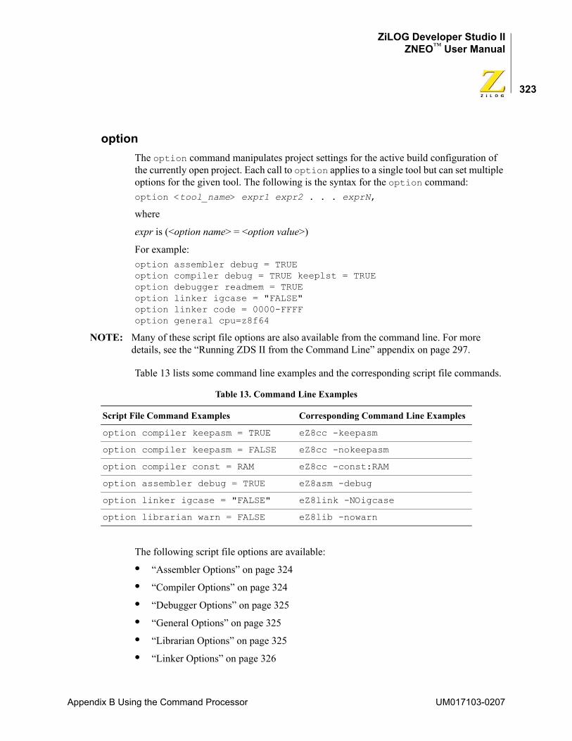
ZiLOG Developer Studio IIZNEO™ User Manual
323
optionThe option command manipulates project settings for the active build configuration of the currently open project. Each call to option applies to a single tool but can set multiple options for the given tool. The following is the syntax for the option command:option <tool_name> expr1 expr2 . . . exprN,
where
expr is (<option name> = <option value>)
For example:option assembler debug = TRUE option compiler debug = TRUE keeplst = TRUE option debugger readmem = TRUE option linker igcase = "FALSE"option linker code = 0000-FFFF option general cpu=z8f64
NOTE: Many of these script file options are also available from the command line. For more details, see the “Running ZDS II from the Command Line” appendix on page 297.
Table 13 lists some command line examples and the corresponding script file commands.
The following script file options are available:
• “Assembler Options” on page 324
• “Compiler Options” on page 324
• “Debugger Options” on page 325
• “General Options” on page 325
• “Librarian Options” on page 325
• “Linker Options” on page 326
Table 13. Command Line Examples
Script File Command Examples Corresponding Command Line Examples
option compiler keepasm = TRUE eZ8cc -keepasm
option compiler keepasm = FALSE eZ8cc -nokeepasm
option compiler const = RAM eZ8cc -const:RAM
option assembler debug = TRUE eZ8asm -debug
option linker igcase = "FALSE" eZ8link -NOigcase
option librarian warn = FALSE eZ8lib -nowarn
Appendix B Using the Command Processor UM017103-0207
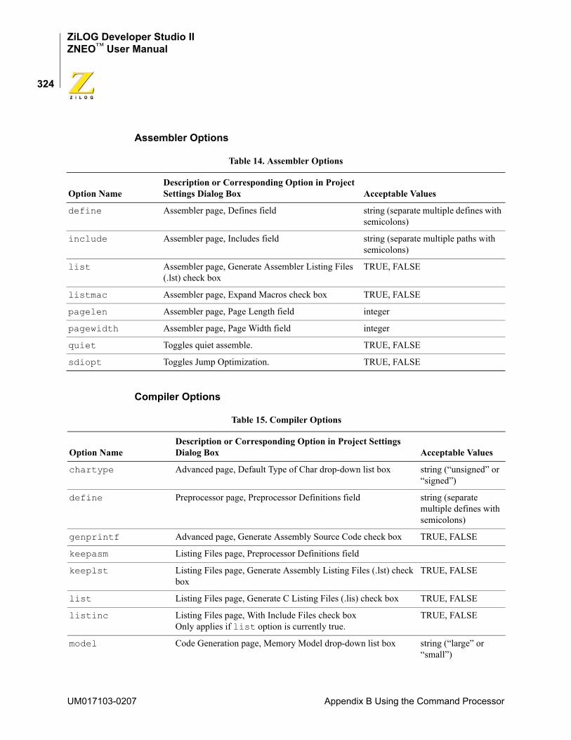
ZiLOG Developer Studio IIZNEO™ User Manual
324
Assembler Options
Compiler Options
Table 14. Assembler Options
Option NameDescription or Corresponding Option in Project Settings Dialog Box Acceptable Values
define Assembler page, Defines field string (separate multiple defines with semicolons)
include Assembler page, Includes field string (separate multiple paths with semicolons)
list Assembler page, Generate Assembler Listing Files (.lst) check box
TRUE, FALSE
listmac Assembler page, Expand Macros check box TRUE, FALSE
pagelen Assembler page, Page Length field integer
pagewidth Assembler page, Page Width field integer
quiet Toggles quiet assemble. TRUE, FALSE
sdiopt Toggles Jump Optimization. TRUE, FALSE
Table 15. Compiler Options
Option NameDescription or Corresponding Option in Project Settings Dialog Box Acceptable Values
chartype Advanced page, Default Type of Char drop-down list box string (“unsigned” or “signed”)
define Preprocessor page, Preprocessor Definitions field string (separate multiple defines with semicolons)
genprintf Advanced page, Generate Assembly Source Code check box TRUE, FALSE
keepasm Listing Files page, Preprocessor Definitions field
keeplst Listing Files page, Generate Assembly Listing Files (.lst) check box
TRUE, FALSE
list Listing Files page, Generate C Listing Files (.lis) check box TRUE, FALSE
listinc Listing Files page, With Include Files check box Only applies if list option is currently true.
TRUE, FALSE
model Code Generation page, Memory Model drop-down list box string (“large” or “small”)
UM017103-0207 Appendix B Using the Command Processor
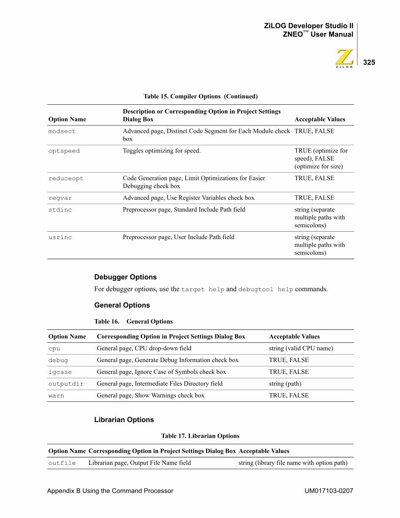
ZiLOG Developer Studio IIZNEO™ User Manual
325
Debugger OptionsFor debugger options, use the target help and debugtool help commands.
General Options
Librarian Options
modsect Advanced page, Distinct Code Segment for Each Module check box
TRUE, FALSE
optspeed Toggles optimizing for speed. TRUE (optimize for speed), FALSE (optimize for size)
reduceopt Code Generation page, Limit Optimizations for Easier Debugging check box
TRUE, FALSE
regvar Advanced page, Use Register Variables check box TRUE, FALSE
stdinc Preprocessor page, Standard Include Path field string (separate multiple paths with semicolons)
usrinc Preprocessor page, User Include Path field string (separate multiple paths with semicolons)
Table 16. General Options
Option Name Corresponding Option in Project Settings Dialog Box Acceptable Values
cpu General page, CPU drop-down field string (valid CPU name)
debug General page, Generate Debug Information check box TRUE, FALSE
igcase General page, Ignore Case of Symbols check box TRUE, FALSE
outputdir General page, Intermediate Files Directory field string (path)
warn General page, Show Warnings check box TRUE, FALSE
Table 17. Librarian Options
Option Name Corresponding Option in Project Settings Dialog Box Acceptable Values
outfile Librarian page, Output File Name field string (library file name with option path)
Table 15. Compiler Options (Continued)
Option NameDescription or Corresponding Option in Project Settings Dialog Box Acceptable Values
Appendix B Using the Command Processor UM017103-0207
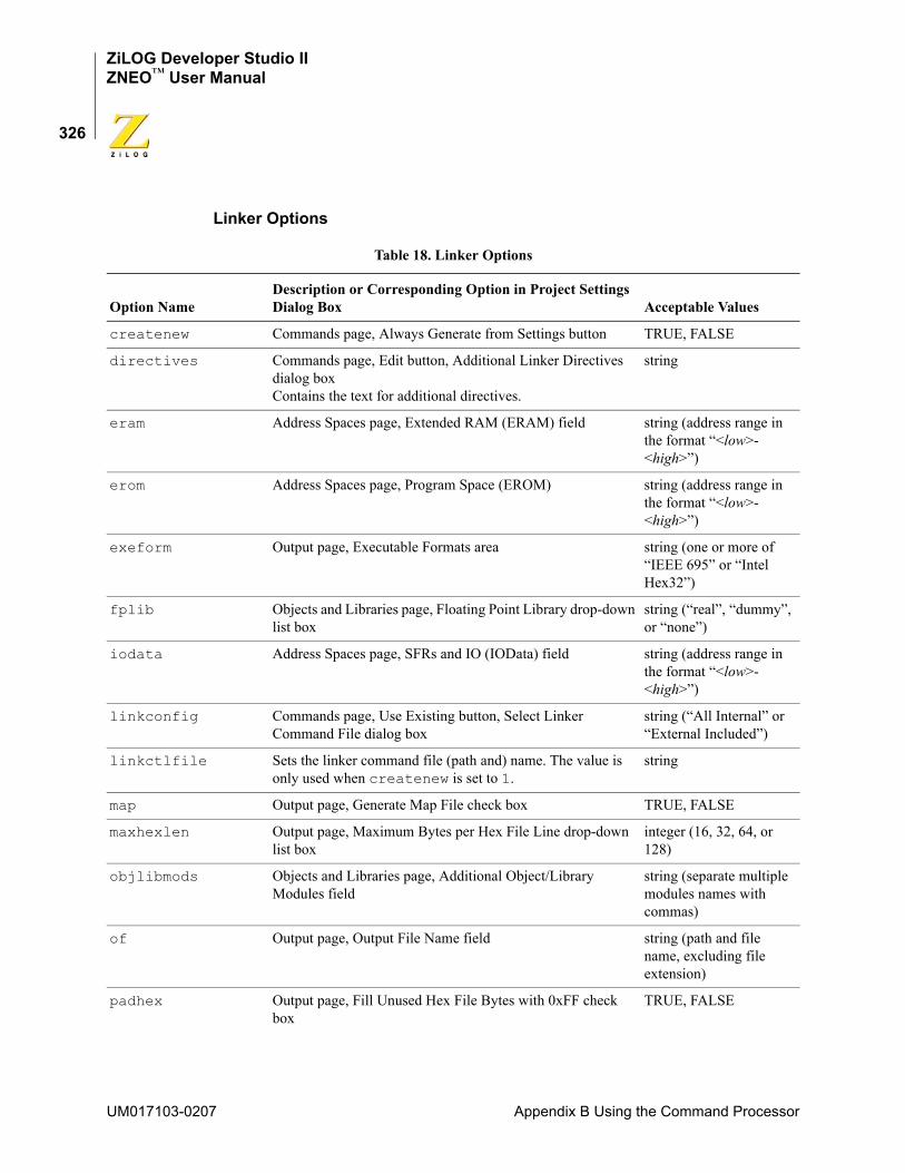
ZiLOG Developer Studio IIZNEO™ User Manual
326
Linker Options
Table 18. Linker Options
Option NameDescription or Corresponding Option in Project Settings Dialog Box Acceptable Values
createnew Commands page, Always Generate from Settings button TRUE, FALSE
directives Commands page, Edit button, Additional Linker Directives dialog boxContains the text for additional directives.
string
eram Address Spaces page, Extended RAM (ERAM) field string (address range in the format “<low>-<high>”)
erom Address Spaces page, Program Space (EROM) string (address range in the format “<low>-<high>”)
exeform Output page, Executable Formats area string (one or more of “IEEE 695” or “Intel Hex32”)
fplib Objects and Libraries page, Floating Point Library drop-down list box
string (“real”, “dummy”, or “none”)
iodata Address Spaces page, SFRs and IO (IOData) field string (address range in the format “<low>-<high>”)
linkconfig Commands page, Use Existing button, Select Linker Command File dialog box
string (“All Internal” or “External Included”)
linkctlfile Sets the linker command file (path and) name. The value is only used when createnew is set to 1.
string
map Output page, Generate Map File check box TRUE, FALSE
maxhexlen Output page, Maximum Bytes per Hex File Line drop-down list box
integer (16, 32, 64, or 128)
objlibmods Objects and Libraries page, Additional Object/Library Modules field
string (separate multiple modules names with commas)
of Output page, Output File Name field string (path and file name, excluding file extension)
padhex Output page, Fill Unused Hex File Bytes with 0xFF check box
TRUE, FALSE
UM017103-0207 Appendix B Using the Command Processor
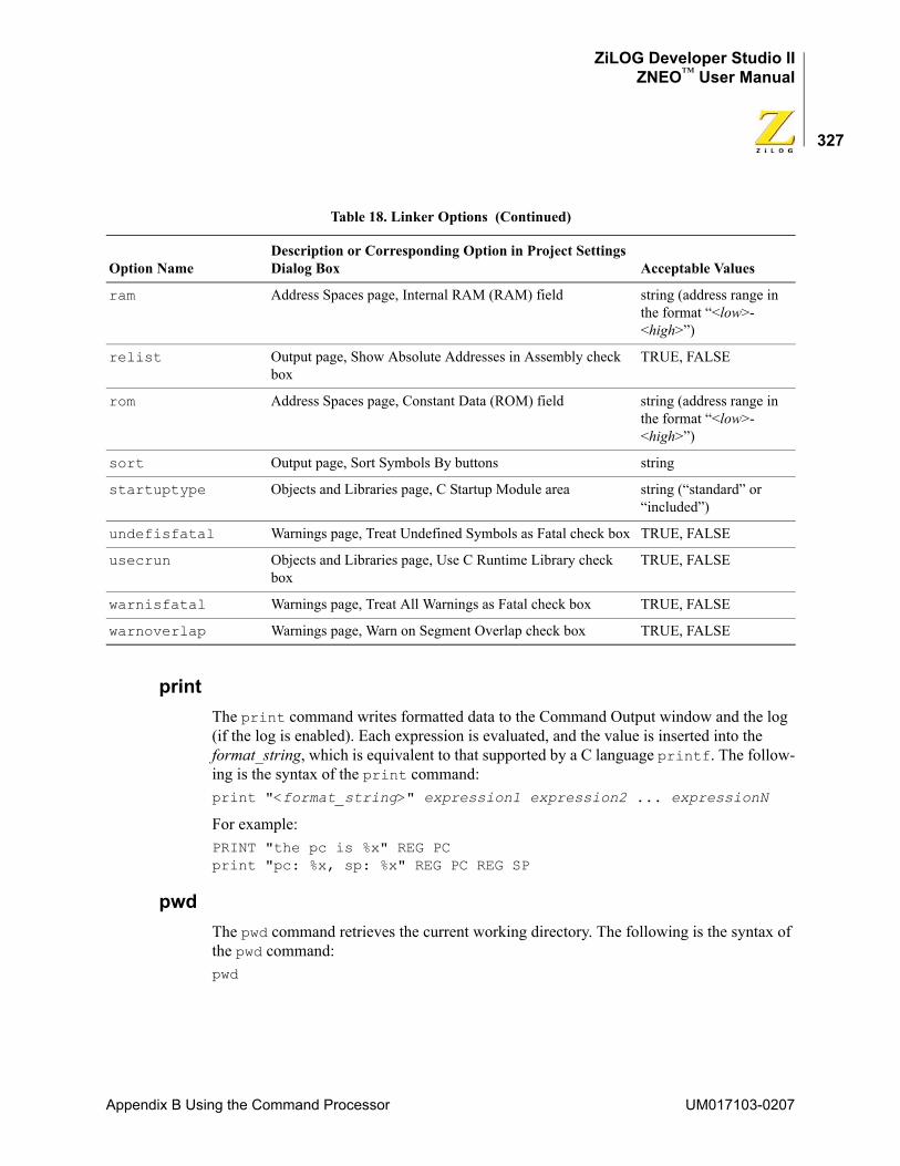
ZiLOG Developer Studio IIZNEO™ User Manual
327
printThe print command writes formatted data to the Command Output window and the log (if the log is enabled). Each expression is evaluated, and the value is inserted into the format_string, which is equivalent to that supported by a C language printf. The follow-ing is the syntax of the print command:print "<format_string>" expression1 expression2 ... expressionN
For example:PRINT "the pc is %x" REG PC print "pc: %x, sp: %x" REG PC REG SP
pwdThe pwd command retrieves the current working directory. The following is the syntax of the pwd command:pwd
ram Address Spaces page, Internal RAM (RAM) field string (address range in the format “<low>-<high>”)
relist Output page, Show Absolute Addresses in Assembly check box
TRUE, FALSE
rom Address Spaces page, Constant Data (ROM) field string (address range in the format “<low>-<high>”)
sort Output page, Sort Symbols By buttons string
startuptype Objects and Libraries page, C Startup Module area string (“standard” or “included”)
undefisfatal Warnings page, Treat Undefined Symbols as Fatal check box TRUE, FALSE
usecrun Objects and Libraries page, Use C Runtime Library check box
TRUE, FALSE
warnisfatal Warnings page, Treat All Warnings as Fatal check box TRUE, FALSE
warnoverlap Warnings page, Warn on Segment Overlap check box TRUE, FALSE
Table 18. Linker Options (Continued)
Option NameDescription or Corresponding Option in Project Settings Dialog Box Acceptable Values
Appendix B Using the Command Processor UM017103-0207
ZiLOG Developer Studio IIZNEO™ User Manual
328
quitThe quit command ends the current debug session. The following is the syntax of the quit command:quit
rebuildThe rebuild command rebuilds the currently open project. This command blocks the execution of other commands until the build process is complete. The following is the syn-tax of the rebuild command:rebuild
resetThe reset command resets execution of program code to the beginning of the program. This command starts a debug session if one has not been started. The following is the syn-tax of the reset command:reset
By default, the reset command resets the PC to symbol 'main'. If you deselect the Reset to Symbol 'main' (Where Applicable) check box on the Debugger tab of the Options dia-log box (see “Options—Debugger Tab” on page 107), the PC resets to the first line of the program.
savememThe savemem command saves the memory content of the specified range into an Intel hex file, a binary file, or a text file. The functionality is similar to the Save to File command available from the context menu in the Memory window (see “Save Memory to a File” on page 287). The following is the syntax of the savemem command:
savemem SPACE="<displayed spacename>" FORMAT=<HEX | BIN |TEXT> "<[PATH\]name>"[STARTADDRESS="<hexadecimal address>"] [ENDADDRESS="<hexadecimal address>"]
If STARTADDRESS and ENDADDRESS are not specified, all the memory contents of a spec-ified space are saved.
For example:savemem SPACE="RDATA" FORMAT=BIN "c:\temp\file.bin" STARTADDRESS="20" ENDADDRESS="100"savemem SPACE="ROM" FORMAT=HEX "c:\temp\file.hex"savemem SPACE="ROM" FORMAT=TEXT "c:\temp\file.txt" STARTADDRESS="1000" ENDADDRESS="2FFF"
UM017103-0207 Appendix B Using the Command Processor
ZiLOG Developer Studio IIZNEO™ User Manual
329
set configThe set config command activates an existing build configuration for or creates a new build configuration in the currently loaded project. The following is the syntax of the set config command:set config "config_name" ["copy_from_config_name"]
The set config command does the following:
• Activates config_name if it exists.
• Creates a new configuration named config_name if it does not yet exist. When complete, the new configuration is made active. When creating a new configuration, the Command Processor copies the initial settings from the copy_from_config_name parameter, if provided. If not provided, the active build configuration is used as the copy source. If config_name exists, the copy_from_config_name parameter is ignored.
NOTE: The active/selected configuration is used with commands like option tool name="value" and build.
stepThe step command performs a single step (stepover) from the current location of the pro-gram counter. If the count is not provided, a single step is performed. This command starts a debug session if one has not been started. The following is the syntax of the step com-mand:step
stepinThe stepin command steps into the function at the PC. If there is no function at the cur-rent PC, this command is equivalent to step. This command starts a debug session if one has not been started. The following is the syntax of the stepin command:stepin
stepoutThe stepout command steps out of the function. This command starts a debug session if one has not been started. The following is the syntax of the stepout command:stepout
stopThe stop command stops the execution of program code. The following is the syntax of the stop command:stop
Appendix B Using the Command Processor UM017103-0207
ZiLOG Developer Studio IIZNEO™ User Manual
330
target copyThe target copy command creates a copy of the existing target with a given name with the given new name. The syntax can take one of two forms:• target copy NAME="<new target name>"
creates a copy of the active target named the value given for NAME.• target copy NAME="<new target name>" SOURCE="<existing target
name>"
creates a copy of the SOURCE target named the value given for NAME.
For example:target copy NAME="mytarget" SOURCE="Sim3"
target createThe target create command creates a new target with the given name and using the given CPU. The following is the syntax of the target create command:target create NAME="<target name>" CPU="<cpu name>"
For example:target create NAME="mytarget" CPU="Z16F2811AL"
target getThe target get command displays the current value for the given data item for the active target. The following is the syntax of the target get command:target get "<data item>"
Use the target setup command to view available data items and current values.
For example:target get "cpu"
target helpThe target help command displays all target commands. The following is the syntax of the target help command:target help
target listThe target list command lists all available targets. The syntax can take one of three forms:
• target list
UM017103-0207 Appendix B Using the Command Processor
ZiLOG Developer Studio IIZNEO™ User Manual
331
displays the names of all available targets (restricted to the currently configured CPU family).
• target list CPU="<cpu name>"
displays the names of all available targets associated with the given CPU name.• target list FAMILY="<family name>"
displays the names of all available targets associated with the given CPU family name.
For example:target list FAMILY="ZNEO"
target optionsNOTE: See a target in the following directory for a list of categories and options:
<ZDS Installation Directory>\targets
where <ZDS Installation Directory> is the directory in which ZiLOG Developer Studio was installed. By default, this would be C:\Program Files\ZiLOG\ZDSII_ZNEO_<version>, where <version> might be 4.11.0 or 5.0.0.
To set a target value, use one of the following syntaxes:target options CATEGORY="<Category>" OPTION="<Option>" "<token name>"="<value to set>" target options CATEGORY="<Category>" "<token name>"="<value to set>"target options "<token name>"="<value to set>"
To select a target, use the following syntax:target options NAME ="<Target Name>"
target saveThe target save command saves a target. To save the selected target, use the following syntax:target save
To save a specified target, use the following syntax:target save NAME="<Target Name>"
For example:target save Name="Sim3"
target setThe target set command sets the given data item to the given data value for the active target or activates a particular target. The syntax can take one of two forms:• target set "<data item>" "<new value>"
Appendix B Using the Command Processor UM017103-0207
ZiLOG Developer Studio IIZNEO™ User Manual
332
Sets data item to new value for the active debug tool. Use target setup to view available data items and current values.
For example:target set "frequency" "20000000"
• target set "<target name>"
Activates the target with the given name. Use target list to view available targets.
target setupThe target setup command displays the current configuration. The following is the syntax of the target setup command:target setup
waitThe wait command instructs the Command Processor to wait the specified milliseconds before executing the next command. The following is the syntax of the wait command:wait <milliseconds>
For example:wait 5000
wait bpThe wait bp command instructs the Command Processor to wait until the debugger stops executing. The optional max_milliseconds parameter provides a method to limit the amount of time a wait takes (that is, wait until the debugger stops or max_milliseconds passes). The following is the syntax of the wait bp command:wait bp [max_milliseconds]
For example:wait bp wait bp 2000
UM017103-0207 Appendix B Using the Command Processor
ZiLOG Developer Studio IIZNEO™ User Manual
333
RUNNING THE FLASH LOADER FROM THE COMMAND PROCESSORYou can run the Flash Loader from the Command field. Command Processor keywords have been added to allow for easy scripting of the Flash loading process. Each of the parameters is persistent, which allows for the repetition of the Flash and verification pro-cesses with a minimum amount of repeated key strokes.
Use the following procedure to run the Flash Loader:
1. Create a project or open a project with a ZNEO microcontroller selected in the CPU Family and CPU fields of the General page of the Project Settings dialog box (see “Project Settings—General Page” on page 54).
2. Set up the USB communication in the Configure Target dialog box (see Figure 61 on page 82).
3. In the Command field (in the Command Processor toolbar), type in one of the following command sequence to use the Flash Loader.
Displaying Flash Help
Setting Up Flash Options
Flash Setup Displays the Flash setup in the Command Output windowFlash Help Displays the Flash command format in the Command Output window
Flash Options "<File Name>" File to be flashedFlash Options OFFSET = "<address>" Offset address in hex fileFlash Options NAUTO Do not automatically select external Flash deviceFlash Options AUTO Automatically select external Flash deviceFlash Options INTMEM Set to internal memoryFlash Options EXTMEM Set to external memoryFlash Options BOTHMEM Set to both internal and external memoryFlash Options NEBF Do not erase before flashFlash Options EBF Erase before flashFlash Options NISN Do not include serial numberFlash Options ISN Include a serial numberFlash Options NPBF Do not page-erase Flash memory; use mass eraseFlash Options PBF Page-erase Flash memoryFlash Options SERIALADDRESS = "<address>" Serial number addressFlash Options SERIALNUMBER = "<Number in Hex>" Initial serial number valueFlash Options SERIALSIZE = <1-8> Number of bytes in serial numberFlash Options INCREMENT = "<Decimal value>" Increment value for serial number
Appendix B Using the Command Processor UM017103-0207
ZiLOG Developer Studio IIZNEO™ User Manual
334
Executing Flash Commands
The Flash Loader dialog box and the Command Processor interface use the same parameters. If an option is not specified with the Command Processor interface, the current setting in the Flash Loader dialog box is used. If a setting is changed in the Command Processor interface, the Flash Loader dialog box settings are changed.
ExamplesThe following are valid examples:FLASH Options INTMEM FLASH Options "c:\testing\test.hex" FLASH BURN REPEAT
orflash options intmem flash options "c:\testing\test.hex" flash burn repeat
The file test.hex is loaded into internal Flash memory. After the Flashing is completed, you are prompted to program an additional unit.FLASH VERIFY
The file test.hex is verified against internal Flash memory.FLASH SETUP
The current Flash Loader parameters settings are displayed in the Command Output window.
Flash READSERIAL Read the serial numberFlash READSERIAL REPEAT Read the serial number and repeatFlash BURNSERIAL Program the serial numberFlash BURNSERIAL REPEAT Program the serial number and repeatFlash ERASE Erase Flash memoryFlash ERASE REPEAT Erase Flash memory and repeatFlash BURN Program Flash memoryFlash BURN REPEAT Program Flash memory and repeatFlash BURNVERIFY Program and verify Flash memory Flash BURNVERIFY REPEAT Program and verify Flash memory and repeatFlash VERIFY Verify Flash memory Flash VERIFY REPEAT Verify Flash memory and repeat
Caution:
UM017103-0207 Appendix B Using the Command Processor
ZiLOG Developer Studio IIZNEO™ User Manual
335
FLASH HELP
The current Flash Loader command options are displayed in the Command Output window.Flash Options NAUTO
The Flash Loader does not automatically select the external Flash device.Flash Options PBF
Page erase is enabled instead of mass erase for internal and external Flash programming.
Appendix B Using the Command Processor UM017103-0207
ZiLOG Developer Studio IIZNEO™ User Manual
336
UM017103-0207 Appendix B Using the Command Processor
ZiLOG Developer Studio IIZNEO™ User Manual
337
Appendix C C Standard LibraryAs described in “Run-Time Library” on page 133, the ZNEO C-Compiler provides a col-lection of run-time libraries. The largest section of these libraries consists of an implemen-tation of much of the C Standard Library.
The ZNEO C-Compiler is a conforming freestanding 1989 ANSI C implementation with some exceptions. In accordance with the definition of a freestanding implementation, the compiler supports the required standard header files <float.h>, <limits.h>, <stdarg.h>, and <stddef.h>. It also supports additional standard header files and ZiLOG-specific nonstandard header files. The latter are described in “Run-Time Library” on page 133.
The standard header files and functions are, with minor exceptions, fully compliant with the ANSI C Standard. The deviations from the ANSI Standard in these files are summa-rized in “Library Files Not Required for Freestanding Implementation” on page 151. The standard header files provided with the compiler are listed in Table 19 and described in detail in “Standard Header Files” on page 338. The following sections describe the use and format of the standard portions of the run-time libraries:
• “Standard Header Files” on page 338
• “Standard Functions” on page 351
Table 19. Standard Headers
Header Description Page
<assert.h> Diagnostics page 340
<ctype.h> Character-handling functions page 340
<errno.h> Error numbers page 339
<float.h> Floating-point limits page 342
<limits.h> Integer limits page 341
<math.h> Math functions page 343
<setjmp.h> Nonlocal jump functions page 346
<stdarg.h> Variable arguments functions page 346
<stddef.h> Standard defines page 339
<stdio.h> Standard input/output functions page 347
<stdlib.h> General utilities functions page 348
<string.h> String-handling functions page 350
Appendix C C Standard Library UM017103-0207
ZiLOG Developer Studio IIZNEO™ User Manual
338
NOTE: The standard include header files are located in the following directory:
<ZDS Installation Directory>\include\std
where <ZDS Installation Directory> is the directory in which ZiLOG Developer Studio was installed. By default, this would be C:\Program Files\ZiLOG\ZDSII_ZNEO_<version>, where <version> might be 4.11.0 or 5.0.0.
STANDARD HEADER FILESEach library function is declared in a header file. The header files can be included in the source files using the #include preprocessor directive. The header file declares a set of related functions, any necessary types, and additional macros needed to facilitate their use.
Header files can be included in any order; each can be included more than once in a given scope with no adverse effect. Header files need to be included in the code before the first reference to any of the functions they declare or types and macros they define.
The following sections describe the standard header files:
• “Errors <errno.h>” on page 339
• “Standard Definitions <stddef.h>” on page 339
• “Diagnostics <assert.h>” on page 340
• “Character Handling <ctype.h>” on page 340
• “Limits <limits.h>” on page 341
• “Floating Point <float.h>” on page 342
• “Mathematics <math.h>” on page 343
• “Nonlocal Jumps <setjmp.h>” on page 346
• “Variable Arguments <stdarg.h>” on page 346
• “Input/Output <stdio.h>” on page 347
• “General Utilities <stdlib.h>” on page 348
• “String Handling <string.h>” on page 350
UM017103-0207 Appendix C C Standard Library
ZiLOG Developer Studio IIZNEO™ User Manual
339
Errors <errno.h>The <errno.h> header defines macros relating to the reporting of error conditions.
Macros
Additional macro definitions, beginning with E and an uppercase letter, can also be speci-fied by the implementation.
Standard Definitions <stddef.h>The following types and macros are defined in several headers referred to in the descrip-tions of the functions declared in that header, as well as the common <stddef.h> stan-dard header.
Macros
Types
EDOM Expands to a distinct nonzero integral constant expression.ERANGE Expands to a distinct nonzero integral constant expression.errno A modifiable value that has type int. Several libraries set errno to a positive value to
indicate an error. errno is initialized to zero at program startup, but it is never set to zero by any library function. The value of errno can be set to nonzero by a library function even if there is no error, depending on the behavior specified for the library function in the ANSI Standard.
NULL Expands to a null pointer constant.offsetof (type, identifier) Expands to an integral constant expression that has type size_t and
provides the offset in bytes, from the beginning of a structure designated by type to the member designated by identifier.
ptrdiff_t Signed integral type of the result of subtracting two pointers.size_t Unsigned integral type of the result of the sizeof operator.wchar_t Integral type whose range of values can represent distinct codes for all members of
the largest extended character set specified among the supported locales.
Appendix C C Standard Library UM017103-0207
ZiLOG Developer Studio IIZNEO™ User Manual
340
Diagnostics <assert.h>The <assert.h> header declares two macros.
Macros
Character Handling <ctype.h>The <ctype.h> header declares several macros and functions useful for testing and map-ping characters. In all cases, the argument is an int, the value of which is represented as an unsigned char or equals the value of the EOF macro. If the argument has any other value, the behavior is undefined.
Macros
NOTE: These are nonstandard macros.
FunctionsThe functions in this section return nonzero (true) if, and only if, the value of the argument c conforms to that in the description of the function. The term printing character refers to a member of a set of characters, each of which occupies one printing position on a display device. The term control character refers to a member of a set of characters that are not printing characters.
Character Testing
NDEBUG The <assert.h> header defines the assert() macro. It refers to the NDEBUG macro that is not defined in the header. If NDEBUG is defined as a macro name before the inclusion of this header, the assert() macro is defined simply as:
#define assert(ignore)((void) 0)assert(expression); Tests the expression and, if false, prints the diagnostics including the
expression, file name, and line number. Also calls exit with nonzero exit code if the expression is false.
TRUE Expands to a constant 1.FALSE Expands to a constant 0.
int isalnum(int c); Tests for alphanumeric character.int isalpha(int c); Tests for alphabetic character.int iscntrl(int c); Tests for control character.int isdigit(int c); Tests for decimal digit.
UM017103-0207 Appendix C C Standard Library
ZiLOG Developer Studio IIZNEO™ User Manual
341
Character Case Mapping
Limits <limits.h>The <limits.h> header defines macros that expand to various limits and parameters.
Macros
If the value of an object of type char sign-extends when used in an expression, the value of CHAR_MIN is the same as that of SCHAR_MIN, and the value of CHAR_MAX is the same as that of SCHAR_MAX. If the value of an object of type char does not sign-extend
int isgraph(int c); Tests for printable character except space.int islower(int c); Tests for lowercase character.int isprint(int c); Tests for printable character.int ispunct(int c); Tests for punctuation character.int isspace(int c); Tests for white-space character.int isupper(int c); Tests for uppercase character.int isxdigit(int c); Tests for hexadecimal digit.
int tolower(int c); Tests character and converts to lowercase if uppercase.
int toupper(int c); Tests character and converts to uppercase if lowercase.
CHAR_BIT Maximum number of bits for smallest object that is not a bit-field (byte).CHAR_MAX Maximum value for an object of type char.CHAR_MIN Minimum value for an object of type char.INT_MAX Maximum value for an object of type int.INT_MIN Minimum value for an object of type int.LONG_MAX Maximum value for an object of type long int.LONG_MIN Minimum value for an object of type long int.SCHAR_MAX Maximum value for an object of type signed char.SCHAR_MIN Minimum value for an object of type signed char.SHRT_MAX Maximum value for an object of type short int.SHRT_MIN Minimum value for an object of type short int.UCHAR_MAX Maximum value for an object of type unsigned char.UINT_MAX Maximum value for an object of type unsigned int.ULONG_MAX Maximum value for an object of type unsigned long int.USHRT_MAX Maximum value for an object of type unsigned short int.MB_LEN_MAX Maximum number of bytes in a multibyte character.
Appendix C C Standard Library UM017103-0207
ZiLOG Developer Studio IIZNEO™ User Manual
342
when used in an expression, the value of CHAR_MIN is 0, and the value of CHAR_MAX is the same as that of UCHAR_MAX.
Floating Point <float.h>The <float.h> header defines macros that expand to various limits and parameters.
Macros
DBL_DIG Number of decimal digits of precision.DBL_MANT_DIG Number of base-FLT_RADIX digits in the floating-point mantissa.DBL_MAX Maximum represented floating-point numbers.DBL_MAX_EXP Maximum integer such that FLT_RADIX raised to that power
approximates a floating-point number in the range of represented numbers.
DBL_MAX_10_EXP Maximum integer such that 10 raised to that power approximates a floating-point number in the range of represented value ((int)log10(DBL_MAX), and so on).
DBL_MIN Minimum represented positive floating-point numbers.DBL_MIN_EXP Minimum negative integer such that FLT_RADIX raised to that power
approximates a positive floating-point number in the range of represented numbers.
DBL_MIN_10_EXP Minimum negative integer such that 10 raised to that power approximates a positive floating-point number in the range of represented values ((int)log10(DBL_MIN), and so on).
FLT_DIG Number of decimal digits of precision.FLT_MANT_DIG Number of base-FLT_RADIX digits in the floating-point mantissa.FLT_MAX Maximum represented floating-point numbers.FLT_MAX_EXP Maximum integer such that FLT_RADIX raised to that power
approximates a floating-point number in the range of represented numbers.
FLT_MAX_10_EXP Maximum integer such that 10 raised to that power approximates a floating-point number in the range of represented value ((int)log10(FLT_MAX), and so on).
FLT_MIN Minimum represented positive floating-point numbers.FLT_MIN_EXP Minimum negative integer such that FLT_RADIX raised to that power
approximates a positive floating-point number in the range of represented numbers
FLT_MIN_10_EXP Minimum negative integer such that 10 raised to that power approximates a positive floating-point number in the range of represented values ((int)log10(FLT_MIN), and so on).
FLT_RADIX Radix of exponent representation.
UM017103-0207 Appendix C C Standard Library
ZiLOG Developer Studio IIZNEO™ User Manual
343
NOTE: The limits for the double and long double data types are the same as that for the float data type for the ZNEO C-Compiler.
Mathematics <math.h>The <math.h> header declares several mathematical functions and defines one macro. The functions take double-precision arguments and return double-precision values. Integer arithmetic functions and conversion functions are discussed later.
NOTE: The double data type is implemented as float in the ZNEO C-Compiler.
Macro
Treatment of Error ConditionsThe behavior of each of these functions is defined for all values of its arguments. Each function must return as if it were a single operation, without generating any externally vis-ible exceptions.
FLT_ROUND Rounding mode for floating-point addition.-1 indeterminable 0 toward zero 1 to nearest 2 toward positive infinity 3 toward negative infinity
LDBL_DIG Number of decimal digits of precision.LDBL_MANT_DIG Number of base-FLT_RADIX digits in the floating-point mantissa.LDBL_MAX Maximum represented floating-point numbers.LDBL_MAX_EXP Maximum integer such that FLT_RADIX raised to that power
approximates a floating-point number in the range of represented numbers.
LDBL_MAX_10_EXP Maximum integer such that 10 raised to that power approximates a floating-point number in the range of represented value ((int)log10(LDBL_MAX), and so on).
LDBL_MIN Minimum represented positive floating-point numbers.LDBL_MIN_EXP Minimum negative integer such that FLT_RADIX raised to that power
approximates a positive floating-point number in the range of represented numbers.
LDBL_MIN_10_EXP Minimum negative integer such that 10 raised to that power approximates a positive floating-point number in the range of represented values ((int)log10(LDBL_MIN), and so on).
HUGE_VAL Expands to a positive double expression, not necessarily represented as a float.
Appendix C C Standard Library UM017103-0207

ZiLOG Developer Studio IIZNEO™ User Manual
344
For all functions, a domain error occurs if an input argument to the function is outside the domain over which the function is defined. On a domain error, the function returns a spec-ified value; the integer expression errno acquires the value of the EDOM macro.
Similarly, a range error occurs if the result of the function cannot be represented as a dou-ble value. If the result overflows (the magnitude of the result is so large that it cannot be represented in an object of the specified type), the function returns the value of the HUGE_VAL macro, with the same sign as the correct value of the function; the integer expression errno acquires the value of the ERANGE macro. If the result underflows (the magnitude of the result is so small that it cannot be represented in an object of the speci-fied type), the function returns zero.
Functions
Trigonometric
The following additional trigonometric functions are provided:
double acos(double x); Calculates arc cosine of x.double asin(double x) Calculates arc sine of x.double atan(double x); Calculates arc tangent of x.double atan2(double y, double x); Calculates arc tangent of y/x.double cos(double x); Calculates cosine of x.double sin(double x); Calculates sine of x.double tan(double x); Calculates tangent of x.
float acosf(float x); Calculates arc cosine of x.float asinf(float x); Calculates arc sine of x.float atanf(float x); Calculates arc tangent of x.float atan2f(float y, float x); Calculates arc tangent of y/x.float cosf(float x); Calculates cosine of x.float sinf(float x); Calculates sine of x.float tanf(float x); Calculates tangent of x.
UM017103-0207 Appendix C C Standard Library
ZiLOG Developer Studio IIZNEO™ User Manual
345
Hyperbolic
The following additional hyperbolic functions are provided:
Exponential
The following additional exponential functions are provided:
Logarithmic
The following additional logarithmic functions are provided:
double cosh(double x); Calculates hyperbolic cosine of x.double sinh(double x); Calculates hyperbolic sine of x.double tanh(double x); Calculates hyperbolic tangent of x.
float coshf(float x); Calculates hyperbolic cosine of x.float sinhf(float x); Calculates hyperbolic sine of x.float tanhf(float x); Calculates hyperbolic tangent of x.
double exp(double x); Calculates exponential function of x.double frexp(double value, int *exp); Shows x as product of mantissa (the value returned by
frexp) and 2 to the n.double ldexp(double x, int exp); Calculates x times 2 to the exp.
float expf(float x); Calculates exponential function of x.float frexpf(float value, int *exp); Shows x as product of mantissa (the value returned by
frexp) and 2 to the n.float ldexpf(float x, int exp); Calculates x times 2 to the exp.
double log(double x); Calculates natural logarithm of x.double log10(double x); Calculates base 10 logarithm of x.double modf(double value, double *iptr); Breaks down x into integer (the value returned by
modf) and fractional (n) parts.
float logf(float x); Calculates natural logarithm of x.float log10f(float x); Calculates base 10 logarithm of x.float modff(float value, float *iptr); Breaks down x into integer (the value returned by
modf) and fractional (n) parts.
Appendix C C Standard Library UM017103-0207
ZiLOG Developer Studio IIZNEO™ User Manual
346
Power
The following additional power functions are provided:
Nearest Integer
The following additional nearest integer functions are provided:
Nonlocal Jumps <setjmp.h>The <setjmp.h> header declares two functions and one type for bypassing the normal function call and return discipline.
Type
Functions
Variable Arguments <stdarg.h>The <stdarg.h> header declares a type and a function and defines two macros for advancing through a list of arguments whose number and types are not known to the called function when it is translated.
double pow(double x, double y); Calculates x to the y.double sqrt(double x); Finds square root of x.
float powf(float x, float y); Calculates x to the y.float sqrtf(float x); Finds square root of x.
double ceil(double x); Finds integer ceiling of x.double fabs(double x); Finds absolute value of x.double floor(double x); Finds largest integer less than or equal to x.double fmod(double x,double y); Finds floating-point remainder of x/y.
float ceilf(float x); Finds integer ceiling of x.float fabsf(float x); Finds absolute value of x.float floorf(float x); Finds largest integer less than or equal to x.float fmodf(float x,float y); Finds floating-point remainder of x/y.
jmp_buf An array type suitable for holding the information needed to restore a calling environment.
int setjmp(jmp_buf env); Saves a stack environment.void longjmp(jmp_buf env, int val); Restores a saved stack environment.
UM017103-0207 Appendix C C Standard Library
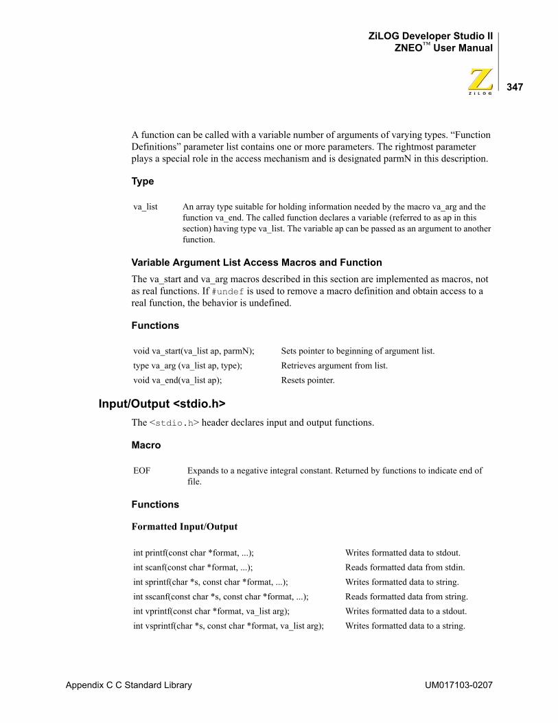
ZiLOG Developer Studio IIZNEO™ User Manual
347
A function can be called with a variable number of arguments of varying types. “Function Definitions” parameter list contains one or more parameters. The rightmost parameter plays a special role in the access mechanism and is designated parmN in this description.
Type
Variable Argument List Access Macros and FunctionThe va_start and va_arg macros described in this section are implemented as macros, not as real functions. If #undef is used to remove a macro definition and obtain access to a real function, the behavior is undefined.
Functions
Input/Output <stdio.h>The <stdio.h> header declares input and output functions.
Macro
Functions
Formatted Input/Output
va_list An array type suitable for holding information needed by the macro va_arg and the function va_end. The called function declares a variable (referred to as ap in this section) having type va_list. The variable ap can be passed as an argument to another function.
void va_start(va_list ap, parmN); Sets pointer to beginning of argument list.type va_arg (va_list ap, type); Retrieves argument from list.void va_end(va_list ap); Resets pointer.
EOF Expands to a negative integral constant. Returned by functions to indicate end of file.
int printf(const char *format, ...); Writes formatted data to stdout.int scanf(const char *format, ...); Reads formatted data from stdin.int sprintf(char *s, const char *format, ...); Writes formatted data to string.int sscanf(const char *s, const char *format, ...); Reads formatted data from string.int vprintf(const char *format, va_list arg); Writes formatted data to a stdout.int vsprintf(char *s, const char *format, va_list arg); Writes formatted data to a string.
Appendix C C Standard Library UM017103-0207
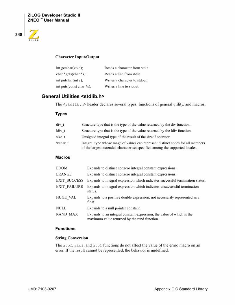
ZiLOG Developer Studio IIZNEO™ User Manual
348
Character Input/Output
General Utilities <stdlib.h>The <stdlib.h> header declares several types, functions of general utility, and macros.
Types
Macros
Functions
String Conversion
The atof, atoi, and atol functions do not affect the value of the errno macro on an error. If the result cannot be represented, the behavior is undefined.
int getchar(void); Reads a character from stdin.char *gets(char *s); Reads a line from stdin.int putchar(int c); Writes a character to stdout.int puts(const char *s); Writes a line to stdout.
div_t Structure type that is the type of the value returned by the div function.ldiv_t Structure type that is the type of the value returned by the ldiv function.size_t Unsigned integral type of the result of the sizeof operator.wchar_t Integral type whose range of values can represent distinct codes for all members
of the largest extended character set specified among the supported locales.
EDOM Expands to distinct nonzero integral constant expressions.ERANGE Expands to distinct nonzero integral constant expressions.EXIT_SUCCESS Expands to integral expression which indicates successful termination status.EXIT_FAILURE Expands to integral expression which indicates unsuccessful termination
status.HUGE_VAL Expands to a positive double expression, not necessarily represented as a
float.NULL Expands to a null pointer constant.RAND_MAX Expands to an integral constant expression, the value of which is the
maximum value returned by the rand function.
UM017103-0207 Appendix C C Standard Library
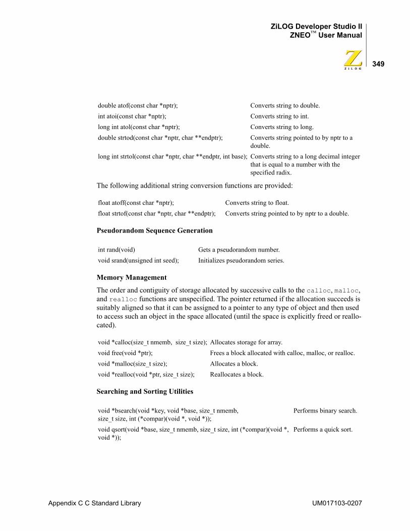
ZiLOG Developer Studio IIZNEO™ User Manual
349
The following additional string conversion functions are provided:
Pseudorandom Sequence Generation
Memory Management
The order and contiguity of storage allocated by successive calls to the calloc, malloc, and realloc functions are unspecified. The pointer returned if the allocation succeeds is suitably aligned so that it can be assigned to a pointer to any type of object and then used to access such an object in the space allocated (until the space is explicitly freed or reallo-cated).
Searching and Sorting Utilities
double atof(const char *nptr); Converts string to double.int atoi(const char *nptr); Converts string to int.long int atol(const char *nptr); Converts string to long.double strtod(const char *nptr, char **endptr); Converts string pointed to by nptr to a
double.long int strtol(const char *nptr, char **endptr, int base); Converts string to a long decimal integer
that is equal to a number with the specified radix.
float atoff(const char *nptr); Converts string to float.float strtof(const char *nptr, char **endptr); Converts string pointed to by nptr to a double.
int rand(void) Gets a pseudorandom number.void srand(unsigned int seed); Initializes pseudorandom series.
void *calloc(size_t nmemb, size_t size); Allocates storage for array.void free(void *ptr); Frees a block allocated with calloc, malloc, or realloc.void *malloc(size_t size); Allocates a block.void *realloc(void *ptr, size_t size); Reallocates a block.
void *bsearch(void *key, void *base, size_t nmemb, size_t size, int (*compar)(void *, void *));
Performs binary search.
void qsort(void *base, size_t nmemb, size_t size, int (*compar)(void *, void *));
Performs a quick sort.
Appendix C C Standard Library UM017103-0207
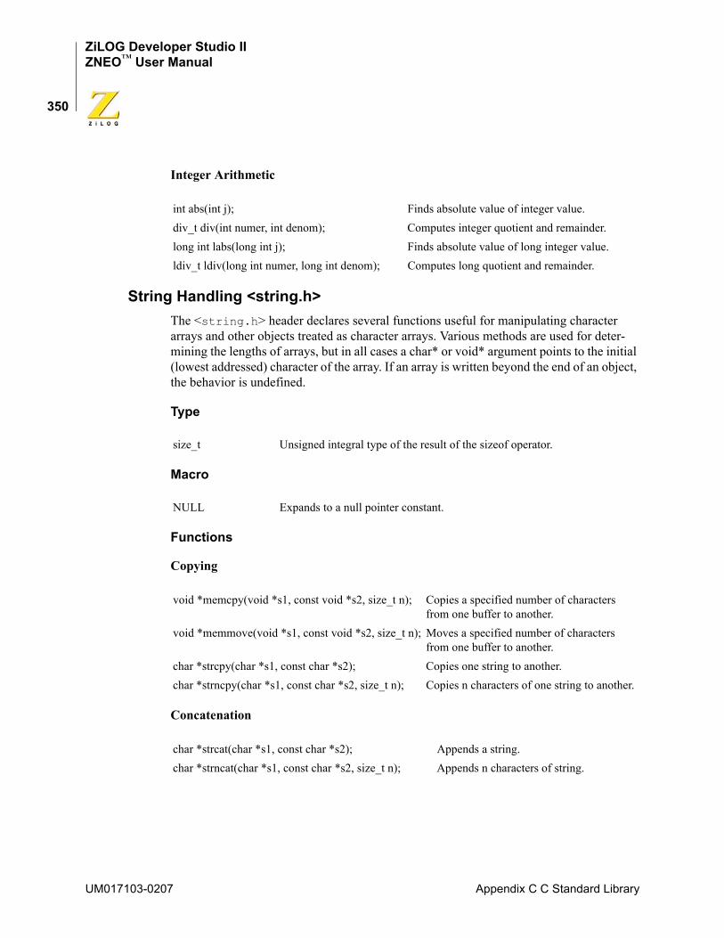
ZiLOG Developer Studio IIZNEO™ User Manual
350
Integer Arithmetic
String Handling <string.h>The <string.h> header declares several functions useful for manipulating character arrays and other objects treated as character arrays. Various methods are used for deter-mining the lengths of arrays, but in all cases a char* or void* argument points to the initial (lowest addressed) character of the array. If an array is written beyond the end of an object, the behavior is undefined.
Type
Macro
Functions
Copying
Concatenation
int abs(int j); Finds absolute value of integer value.div_t div(int numer, int denom); Computes integer quotient and remainder.long int labs(long int j); Finds absolute value of long integer value.ldiv_t ldiv(long int numer, long int denom); Computes long quotient and remainder.
size_t Unsigned integral type of the result of the sizeof operator.
NULL Expands to a null pointer constant.
void *memcpy(void *s1, const void *s2, size_t n); Copies a specified number of characters from one buffer to another.
void *memmove(void *s1, const void *s2, size_t n); Moves a specified number of characters from one buffer to another.
char *strcpy(char *s1, const char *s2); Copies one string to another.char *strncpy(char *s1, const char *s2, size_t n); Copies n characters of one string to another.
char *strcat(char *s1, const char *s2); Appends a string.char *strncat(char *s1, const char *s2, size_t n); Appends n characters of string.
UM017103-0207 Appendix C C Standard Library
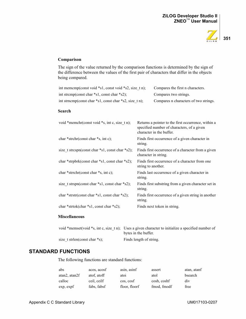
ZiLOG Developer Studio IIZNEO™ User Manual
351
Comparison
The sign of the value returned by the comparison functions is determined by the sign of the difference between the values of the first pair of characters that differ in the objects being compared.
Search
Miscellaneous
STANDARD FUNCTIONSThe following functions are standard functions:
int memcmp(const void *s1, const void *s2, size_t n); Compares the first n characters.int strcmp(const char *s1, const char *s2); Compares two strings.int strncmp(const char *s1, const char *s2, size_t n); Compares n characters of two strings.
void *memchr(const void *s, int c, size_t n); Returns a pointer to the first occurrence, within a specified number of characters, of a given character in the buffer.
char *strchr(const char *s, int c); Finds first occurrence of a given character in string.
size_t strcspn(const char *s1, const char *s2); Finds first occurrence of a character from a given character in string.
char *strpbrk(const char *s1, const char *s2); Finds first occurrence of a character from one string to another.
char *strrchr(const char *s, int c); Finds last occurrence of a given character in string.
size_t strspn(const char *s1, const char *s2); Finds first substring from a given character set in string.
char *strstr(const char *s1, const char *s2); Finds first occurrence of a given string in another string.
char *strtok(char *s1, const char *s2); Finds next token in string.
void *memset(void *s, int c, size_t n); Uses a given character to initialize a specified number of bytes in the buffer.
size_t strlen(const char *s); Finds length of string.
abs acos, acosf asin, asinf assert atan, atanfatan2, atan2f atof, atoff atoi atol bsearchcalloc ceil, ceilf cos, cosf cosh, coshf divexp, expf fabs, fabsf floor, floorf fmod, fmodf free
Appendix C C Standard Library UM017103-0207
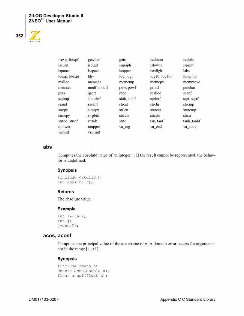
ZiLOG Developer Studio IIZNEO™ User Manual
352
absComputes the absolute value of an integer j. If the result cannot be represented, the behav-ior is undefined.
Synopsis#include <stdlib.h> int abs(int j);
ReturnsThe absolute value.
Exampleint I=-5632; int j; j=abs(I);
acos, acosfComputes the principal value of the arc cosine of x. A domain error occurs for arguments not in the range [-1,+1].
Synopsis#include <math.h> double acos(double x); float acosf(float x);
frexp, frexpf getchar gets isalnum isalphaiscntrl isdigit isgraph islower isprintispunct isspace isupper isxdigit labsldexp, ldexpf ldiv log, logf log10, log10f longjmpmalloc memchr memcmp memcpy memmovememset modf, modff pow, powf printf putcharputs qsort rand realloc scanfsetjmp sin, sinf sinh, sinhf sprintf sqrt, sqrtfsrand sscanf strcat strchr strcmpstrcpy strcspn strlen strncat strncmpstrncpy strpbrk strrchr strspn strstrstrtod, strtof strtok strtol tan, tanf tanh, tanhftolower toupper va_arg va_end va_startvprintf vsprintf
UM017103-0207 Appendix C C Standard Library
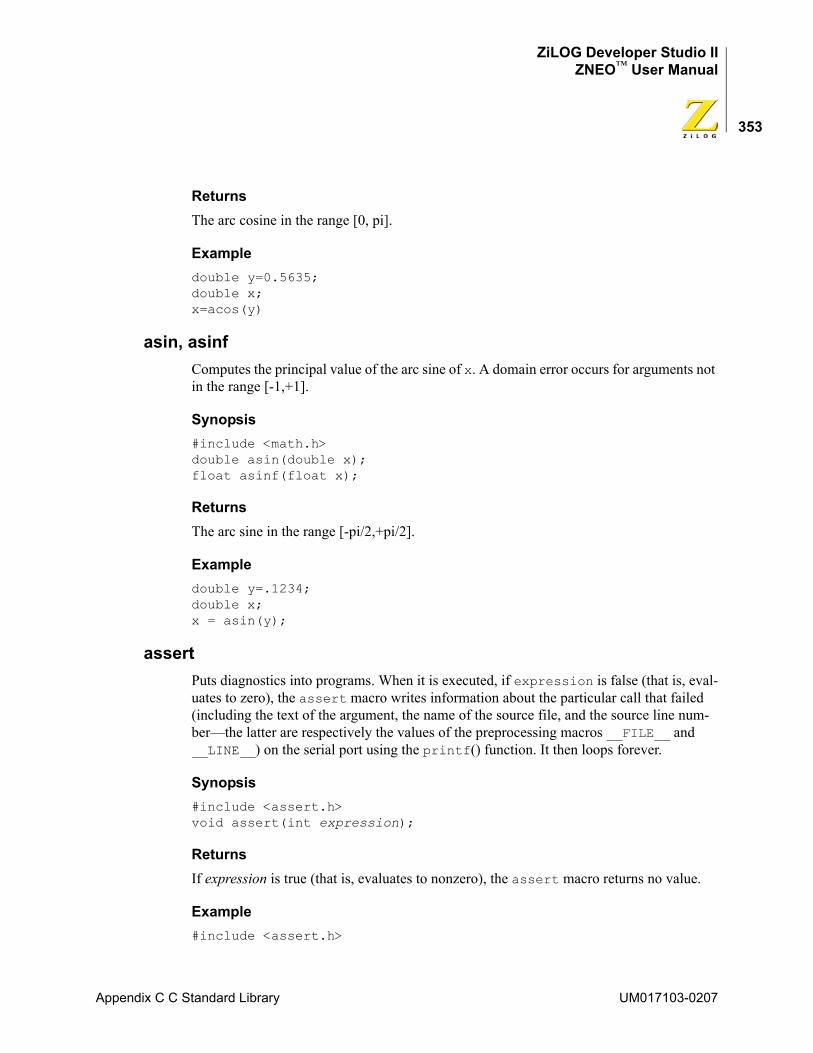
ZiLOG Developer Studio IIZNEO™ User Manual
353
ReturnsThe arc cosine in the range [0, pi].
Exampledouble y=0.5635; double x; x=acos(y)
asin, asinfComputes the principal value of the arc sine of x. A domain error occurs for arguments not in the range [-1,+1].
Synopsis#include <math.h> double asin(double x); float asinf(float x);
ReturnsThe arc sine in the range [-pi/2,+pi/2].
Exampledouble y=.1234; double x; x = asin(y);
assertPuts diagnostics into programs. When it is executed, if expression is false (that is, eval-uates to zero), the assert macro writes information about the particular call that failed (including the text of the argument, the name of the source file, and the source line num-ber—the latter are respectively the values of the preprocessing macros __FILE__ and __LINE__) on the serial port using the printf() function. It then loops forever.
Synopsis#include <assert.h> void assert(int expression);
ReturnsIf expression is true (that is, evaluates to nonzero), the assert macro returns no value.
Example#include <assert.h>
Appendix C C Standard Library UM017103-0207
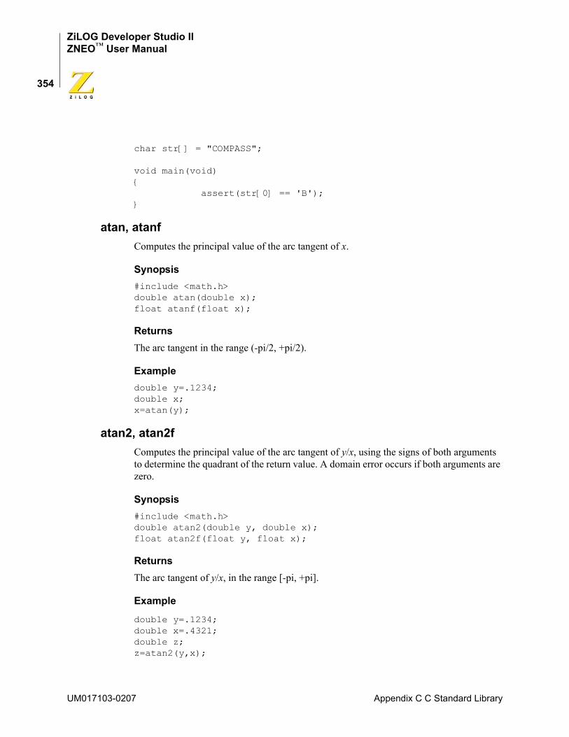
ZiLOG Developer Studio IIZNEO™ User Manual
354
char str[] = "COMPASS";
void main(void){
assert(str[0] == 'B');}
atan, atanfComputes the principal value of the arc tangent of x.
Synopsis#include <math.h> double atan(double x); float atanf(float x);
ReturnsThe arc tangent in the range (-pi/2, +pi/2).
Exampledouble y=.1234; double x; x=atan(y);
atan2, atan2fComputes the principal value of the arc tangent of y/x, using the signs of both arguments to determine the quadrant of the return value. A domain error occurs if both arguments are zero.
Synopsis#include <math.h> double atan2(double y, double x); float atan2f(float y, float x);
ReturnsThe arc tangent of y/x, in the range [-pi, +pi].
Example
double y=.1234; double x=.4321; double z; z=atan2(y,x);
UM017103-0207 Appendix C C Standard Library
ZiLOG Developer Studio IIZNEO™ User Manual
355
atof, atoffConverts the string pointed to by nptr to double representation. Except for the behavior on error, atof is equivalent to strtod (nptr, (char **)NULL), and atoff is equiva-lent to strtof (nptr, (char **)NULL).
Synopsis#include <stdlib.h> double atof(const char *nptr); float atoff(const char *nptr);
ReturnsThe converted value.
Examplechar str []="1.234"; double x; x= atof(str);
atoiConverts the string pointed to by nptr to int representation. Except for the behavior on error, it is equivalent to (int)strtol(nptr, (char **)NULL, 10).
Synopsis#include <stdlib.h> int atoi(const char *nptr);
ReturnsThe converted value.
Examplechar str []="50"; int x; x=atoi(str);
atolConverts the string pointed to by nptr to long int representation. Except for the behavior on error, it is equivalent to strtol(nptr, (char **)NULL, 10).
Synopsis#include <stdlib.h> long int atol(const char *nptr);
Appendix C C Standard Library UM017103-0207
ZiLOG Developer Studio IIZNEO™ User Manual
356
ReturnsThe converted value.
Examplechar str[]="1234567"; long int x; x=atol(str);
bsearchSearches an array of nmemb objects, the initial member of which is pointed to by base, for a member that matches the object pointed to by key. The size of each object is specified by size.
The array has been previously sorted in ascending order according to a comparison func-tion pointed to by compar, which is called with two arguments that point to the objects being compared. The compar function returns an integer less than, equal to, or greater than zero if the first argument is considered to be respectively less than, equal to, or greater than the second.
Synopsis#include <stdlib.h> void *bsearch(const void *key, const void *base, size_t nmemb, size_t size, int (*compar)(const void *, const void *));
ReturnsA pointer to the matching member of the array or a null pointer, if no match is found.
Example
#include <stdlib.h>int list[]={2,5,8,9};int k=8;
int compare (const void * x, const void * y);int main(void){
int *result; result = bsearch(&k, list, 4, sizeof(int), compare);
}
int compare (const void * x, const void * y) {
int a = *(int *) x; int b = *(int *) y; if (a < b) return -1;
UM017103-0207 Appendix C C Standard Library
ZiLOG Developer Studio IIZNEO™ User Manual
357
if (a == b)return 0; return 1;
}
The compare function prototype is, as shown in the preceding example:int compare (const void * x, const void * y);
callocAllocates space for an array of nmemb objects, each of whose size is size. The space is initialized to all bits zero.
Synopsis#include <stdlib.h> void *calloc(size_t nmemb, size_t size);
ReturnsA pointer to the start (lowest byte address) of the allocated space. If the space cannot be allocated, or if nmemb or size is zero, the calloc function returns a null pointer.
Examplechar *buf; buf = (char*)calloc(40, sizeof(char)); if (buf != NULL) /*success*/ else /*fail*/
ceil, ceilfComputes the smallest integer not less than x.
Synopsis#include <math.h> double ceil(double x); float ceilf(float x);
ReturnsThe smallest integer not less than x, expressed as a double for ceil and expressed as a float for ceilf.
Exampledouble y=1.45; double x; x=ceil(y);
Appendix C C Standard Library UM017103-0207
ZiLOG Developer Studio IIZNEO™ User Manual
358
cos, cosfComputes the cosine of x (measured in radians). A large magnitude argument can yield a result with little or no significance.
Synopsis#include <math.h> double cos(double x); float cosf(float x);
ReturnsThe cosine value.
Exampledouble y=.1234; double x; x=cos(y);
cosh, coshfComputes the hyperbolic cosine of x. A range error occurs if the magnitude of x is too large.
Synopsis#include <math.h> double cosh(double x); float coshf(float x);
ReturnsThe hyperbolic cosine value.
Exampledouble y=.1234; double x x=cosh(y);
divComputes the quotient and remainder of the division of the numerator numer by the denominator denom. If the division is inexact, the sign of the quotient is that of the mathematical quotient, and the magnitude of the quotient is the largest integer less than the magnitude of the mathematical quotient.
UM017103-0207 Appendix C C Standard Library
ZiLOG Developer Studio IIZNEO™ User Manual
359
Synopsis#include <stdlib.h> div_t div(int numer, int denom);
ReturnsA structure of type div_t, comprising both the quotient and the remainder. The structure contains the following members, in either order:int quot; /* quotient */ int rem; /* remainder */
Exampleint x=25; int y=3; div_t t; int q; int r; t=div (x,y); q=t.quot; r=t.rem;
exp, expfComputes the exponential function of x. A range error occurs if the magnitude of x is too large.
Synopsis#include <math.h> double exp(double x); float expf(float x);
ReturnsThe exponential value.
Exampledouble y=.1234; double x; x=exp(y);
Appendix C C Standard Library UM017103-0207
ZiLOG Developer Studio IIZNEO™ User Manual
360
fabs, fabsfComputes the absolute value of a floating-point number x.
Synopsis#include <math.h> double fabs(double x); float fabsf(float x);
ReturnsThe absolute value of x.
Exampledouble y=6.23; double x; x=fabs(y);
floor, floorfComputes the largest integer not greater than x.
Synopsis#include <math.h> double floor(double x); float floorf(float x);
ReturnsThe largest integer not greater than x, expressed as a double for floor and expressed as a float for floorf.
Exampledouble y=6.23; double x; x=floor(y);
fmod, fmodfComputes the floating-point remainder of x/y. If the quotient of x/y cannot be represented, the behavior is undefined.
Synopsis#include <math.h> double fmod(double x, double y); float fmodf(float x, float y);
UM017103-0207 Appendix C C Standard Library
ZiLOG Developer Studio IIZNEO™ User Manual
361
ReturnsThe value of x if y is zero. Otherwise, it returns the value f, which has the same sign as x, such that x - i * y + f for some integer i, where the magnitude of f is less than the magni-tude of y.
Exampledouble y=7.23; double x=2.31; double z; z=fmod(y,x);
freeCauses the space pointed to by ptr to be deallocated, that is, made available for further allocation. If ptr is a null pointer, no action occurs. Otherwise, if the argument does not match a pointer earlier returned by the calloc, malloc, or realloc function, or if the space has been deallocated by a call to free or realloc, the behavior is undefined. If freed space is referenced, the behavior is undefined.
Synopsis#include <stdlib.h> void free(void *ptr);
Examplechar *buf; buf=(char*) calloc(40, sizeof(char)); free(buf);
frexp, frexpfBreaks a floating-point number into a normalized fraction and an integral power of 2. It stores the integer in the int object pointed to by exp.
Synopsis#include <math.h> double frexp(double value, int *exp); float frexpf(float value, int *exp);
ReturnsThe value x, such that x is a double (frexp) or float (frexpf) with magnitude in the interval [1/2, 1] or zero, and value equals x times 2 raised to the power *exp. If value is zero, both parts of the result are zero.
Appendix C C Standard Library UM017103-0207
ZiLOG Developer Studio IIZNEO™ User Manual
362
Exampledouble y, x=16.4; int n; y=frexp(x,&n);
getcharWaits for the next character to appear at the serial port and return its value.
Synopsis#include <stdio.h> int getchar(void);
ReturnsThe next character from the input stream pointed to by stdin. If the stream is at end-of-file, the end-of-file indicator for the stream is set, and getchar returns EOF. If a read error occurs, the error indicator for the stream is set, and getchar returns EOF.
Exampleint i; i=getchar();
NOTE: The UART needs to be initialized using the ZiLOG init_uart() function. See “init_uart” on page 137.
getsReads characters from the input stream into the array pointed to by s, until end-of-file is encountered or a new-line character is read. The new-line character is discarded, and a null character is written immediately after the last character read into the array.
Synopsis#include <stdio.h> char *gets(char *s);
ReturnsThe value of s, if successful. If a read error occurs during the operation, the array contents are indeterminate, and a null pointer is returned.
Examplechar *r; char buf [80]; r=gets(buf);
UM017103-0207 Appendix C C Standard Library
ZiLOG Developer Studio IIZNEO™ User Manual
363
if (r==NULL) /*No input*/
NOTE: The UART needs to be initialized using the ZiLOG init_uart() function. See “init_uart” on page 137.
isalnumTests for any character for which isalpha or isdigit is true.
Synopsisinclude <ctype.h> int isalnum(int c);
Exampleint r; char c='a'; r=isalnum(c);
isalphaTests for any character for which isupper or islower is true.
Synopsis#include <ctype.h> int isalpha(int c);
Exampleint r; char c='a'; r=isalpha(c);
iscntrlTests for any control character.
Synopsis#include <ctype.h> int iscntrl(int c);
Exampleint r; char c=NULL; r=iscntrl(c);
Appendix C C Standard Library UM017103-0207
ZiLOG Developer Studio IIZNEO™ User Manual
364
isdigitTests for any decimal digit.
Synopsis#include <ctype.h> int isdigit(int c);
Exampleint r; char c='4'; r=isdigit(c);
isgraphTests for any printing character except space (' ').
Synopsis#include <ctype.h> int isgraph(int c);
Exampleint r; char c=''; r=isgraph(c);
islowerTests for any lowercase letter 'a' to 'z'.
Synopsis#include <ctype.h> int islower(int c);
Exampleint r; char c='a'; r=islower(c);
UM017103-0207 Appendix C C Standard Library
ZiLOG Developer Studio IIZNEO™ User Manual
365
isprintTests for any printing character including space (' ').
Synopsis#include <ctype.h> int isprint(int c);
Exampleint r; char c='1'; r=isprint(c);
ispunctTests for any printing character except space (' ') or a character for which isalnum is true.
Synopsis#include <ctype.h> int ispunct(int c);
Exampleint r; char c='a'; r=ispunct(c);
isspaceTests for the following white-space characters: space (' '), form feed ('\f'), new line ('\n'), carriage return ('\r'), horizontal tab ('\t'), or vertical tab ('\v').
Synopsis#include <ctype.h> int isspace(int c);
Exampleint r; char c=''; r=isspace(c);
Appendix C C Standard Library UM017103-0207
ZiLOG Developer Studio IIZNEO™ User Manual
366
isupperTests for any uppercase letter 'A' to 'Z'.
Synopsis#include <ctype.h> int isupper(int c);
Exampleint r; char c='a'; r=isupper(c);
isxdigitTests for any hexadecimal digit '0' to '9' and 'A' to 'F'.
Synopsis#include <ctype.h> int isxdigit(int c);
Exampleint r; char c='f'; r=isxdigit(c);
labsComputes the absolute value of a long int j.
Synopsis#include <stdlib.h> long labs(long j);
Examplelong i=-193250; long j j=labs(i);
UM017103-0207 Appendix C C Standard Library
ZiLOG Developer Studio IIZNEO™ User Manual
367
ldexp, ldexpfMultiplies a floating-point number by an integral power of 2. A range error can occur.
Synopsis#include <math.h> double ldexp(double x, int exp); float ldexpf(float x, int exp);
ReturnsThe value of x times 2 raised to the power of exp.
Exampledouble x=1.235 int exp=2; double y; y=ldexp(x,exp);
ldivComputes the quotient and remainder of the division of the numerator numer by the denominator denom. If the division is inexact, the sign of the quotient is that of the mathematical quotient, and the magnitude of the quotient is the largest integer less than the magnitude of the mathematical quotient.
Synopsis#include <stdlib.h> ldiv_t ldiv(long numer, long denom);
Examplelong x=25000; long y=300; ldiv_t t; long q; long r; t=ldiv(x,y); q=t.quot; r=t.rem;
Appendix C C Standard Library UM017103-0207
ZiLOG Developer Studio IIZNEO™ User Manual
368
log, logfComputes the natural logarithm of x. A domain error occurs if the argument is negative. A range error occurs if the argument is zero.
Synopsis#include <math.h> double log(double x); float logf(float x);
ReturnsThe natural logarithm.
Exampledouble x=2.56; double y; y=log(x);
log10, log10fComputes the base-ten logarithm of x. A domain error occurs if the argument is negative. A range error occurs if the argument is zero.
Synopsis#include <math.h> double log10(double x); float log10f(float x);
ReturnsThe base-ten logarithm.
Exampledouble x=2.56; double y; y=log10(x);
longjmpRestores the environment saved by the most recent call to setjmp in the same invocation of the program, with the corresponding jmp_buf argument. If there has been no such call, or if the function containing the call to setjmp has executed a return statement in the interim, the behavior is undefined.
UM017103-0207 Appendix C C Standard Library
ZiLOG Developer Studio IIZNEO™ User Manual
369
All accessible objects have values as of the time longjmp was called, except that the values of objects of automatic storage class that do not have volatile type and have been changed between the setjmp and longjmp call are indeterminate.
As it bypasses the usual function call and returns mechanisms, the longjmp function exe-cutes correctly in contexts of interrupts, signals, and any of their associated functions. However, if the longjmp function is invoked from a nested signal handler (that is, from a function invoked as a result of a signal raised during the handling of another signal), the behavior is undefined.
Synopsis#include <setjmp.h> void longjmp(jmp_buf env, int val);
ReturnsAfter longjmp is completed, program execution continues as if the corresponding call to setjmp had just returned the value specified by val. The longjmp function cannot cause setjmp to return the value 0; if val is 0, setjmp returns the value 1.
Exampleint i; jmp_buf env; i=setjmp(env); longjmp(env,i);
mallocAllocates space for an object whose size is specified by size.
NOTE: The existing implementation of malloc() depends on the heap area being located from the bottom of the heap (referred to by the symbol __heapbot) to the top of the stack (SP). Care must be taken to avoid holes in this memory range. Otherwise, the malloc() function might not be able to allocate a valid memory object.
Synopsis#include <stdlib.h> void *malloc(size_t size);
ReturnsA pointer to the start (lowest byte address) of the allocated space. If the space cannot be allocated, or if size is zero, the malloc function returns a null pointer.
Appendix C C Standard Library UM017103-0207
ZiLOG Developer Studio IIZNEO™ User Manual
370
Examplechar *buf; buf=(char *) malloc(40*sizeof(char)); if(buf !=NULL)
/*success*/ else
/*fail*/
memchrLocates the first occurrence of c (converted to an unsigned char) in the initial n charac-ters of the object pointed to by s.
Synopsis#include <string.h> void *memchr(const void *s, int c, size_t n);
ReturnsA pointer to the located character or a null pointer if the character does not occur in the object.
Examplechar *p1; char str[]="COMPASS"; c='p'; p1=memchr(str,c,sizeof(char));
memcmpCompares the first n characters of the object pointed to by s2 to the object pointed to by s1.
Synopsis#include <string.h> int memcmp(const void *s1, const void *s2, size_t n);
ReturnsAn integer greater than, equal to, or less than zero, according as the object pointed to by s1 is greater than, equal to, or less than the object pointed to by s2.
Examplechar s1[]="COMPASS"; char s2[]="IDE"; int res; res=memcmp(s1, s2, sizeof (char));
UM017103-0207 Appendix C C Standard Library
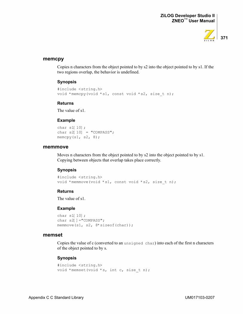
ZiLOG Developer Studio IIZNEO™ User Manual
371
memcpyCopies n characters from the object pointed to by s2 into the object pointed to by s1. If the two regions overlap, the behavior is undefined.
Synopsis#include <string.h> void *memcpy(void *s1, const void *s2, size_t n);
ReturnsThe value of s1.
Examplechar s1[10]; char s2[10] = "COMPASS"; memcpy(s1, s2, 8);
memmoveMoves n characters from the object pointed to by s2 into the object pointed to by s1. Copying between objects that overlap takes place correctly.
Synopsis#include <string.h> void *memmove(void *s1, const void *s2, size_t n);
ReturnsThe value of s1.
Examplechar s1[10]; char s2[]="COMPASS"; memmove(s1, s2, 8*sizeof(char));
memsetCopies the value of c (converted to an unsigned char) into each of the first n characters of the object pointed to by s.
Synopsis#include <string.h> void *memset(void *s, int c, size_t n);
Appendix C C Standard Library UM017103-0207
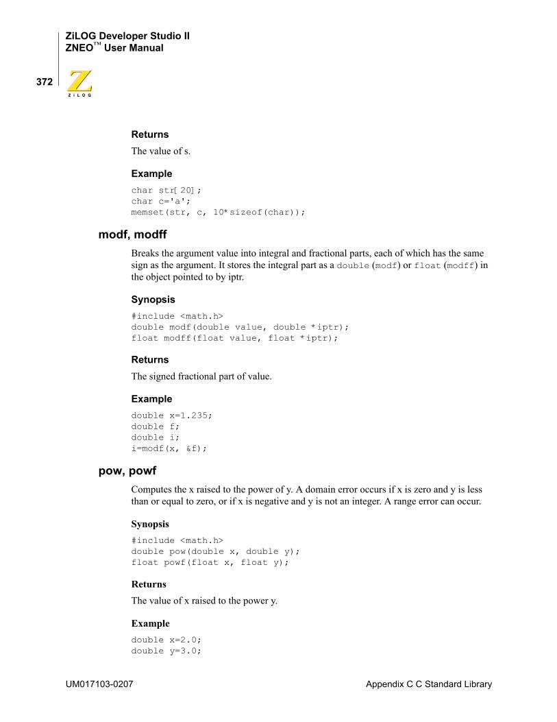
ZiLOG Developer Studio IIZNEO™ User Manual
372
ReturnsThe value of s.
Examplechar str[20]; char c='a'; memset(str, c, 10*sizeof(char));
modf, modffBreaks the argument value into integral and fractional parts, each of which has the same sign as the argument. It stores the integral part as a double (modf) or float (modff) in the object pointed to by iptr.
Synopsis#include <math.h> double modf(double value, double *iptr); float modff(float value, float *iptr);
ReturnsThe signed fractional part of value.
Exampledouble x=1.235; double f; double i; i=modf(x, &f);
pow, powfComputes the x raised to the power of y. A domain error occurs if x is zero and y is less than or equal to zero, or if x is negative and y is not an integer. A range error can occur.
Synopsis#include <math.h> double pow(double x, double y); float powf(float x, float y);
ReturnsThe value of x raised to the power y.
Exampledouble x=2.0; double y=3.0;
UM017103-0207 Appendix C C Standard Library
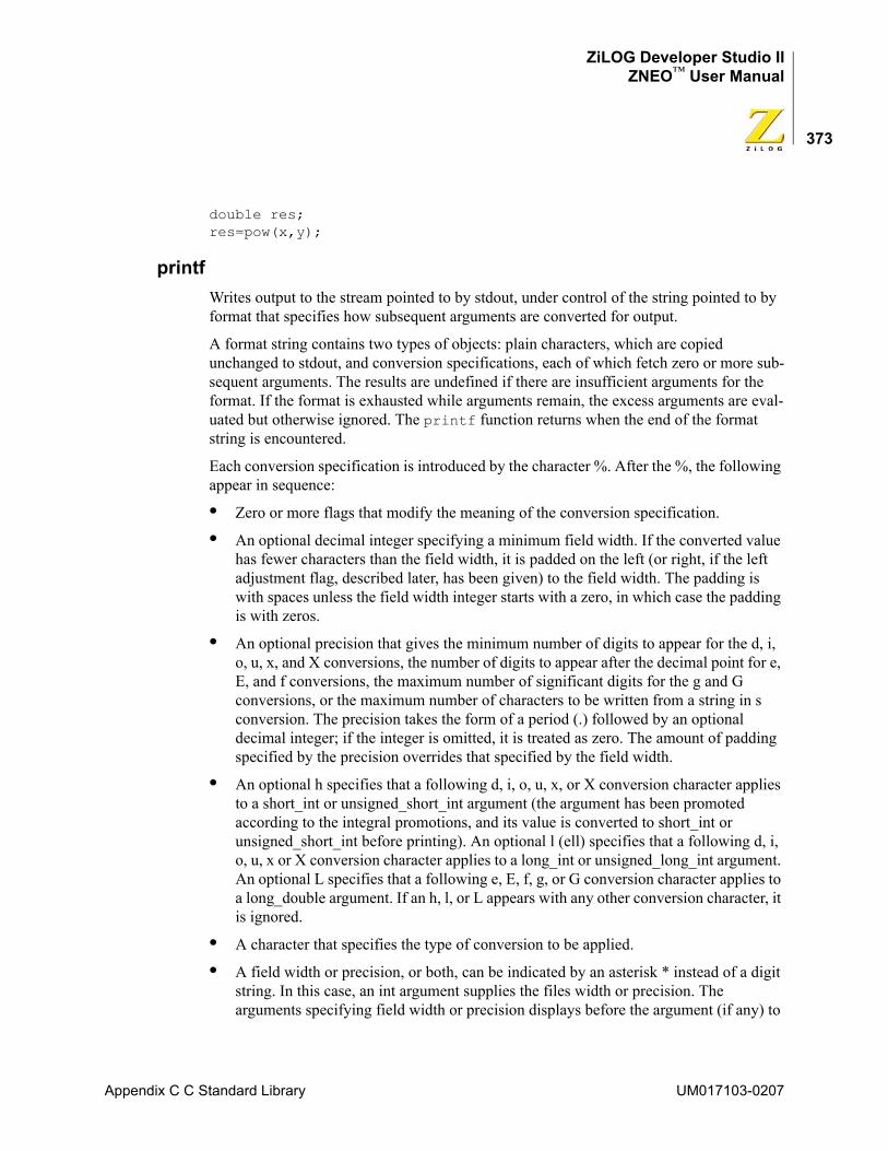
ZiLOG Developer Studio IIZNEO™ User Manual
373
double res; res=pow(x,y);
printfWrites output to the stream pointed to by stdout, under control of the string pointed to by format that specifies how subsequent arguments are converted for output.
A format string contains two types of objects: plain characters, which are copied unchanged to stdout, and conversion specifications, each of which fetch zero or more sub-sequent arguments. The results are undefined if there are insufficient arguments for the format. If the format is exhausted while arguments remain, the excess arguments are eval-uated but otherwise ignored. The printf function returns when the end of the format string is encountered.
Each conversion specification is introduced by the character %. After the %, the following appear in sequence:
• Zero or more flags that modify the meaning of the conversion specification.
• An optional decimal integer specifying a minimum field width. If the converted value has fewer characters than the field width, it is padded on the left (or right, if the left adjustment flag, described later, has been given) to the field width. The padding is with spaces unless the field width integer starts with a zero, in which case the padding is with zeros.
• An optional precision that gives the minimum number of digits to appear for the d, i, o, u, x, and X conversions, the number of digits to appear after the decimal point for e, E, and f conversions, the maximum number of significant digits for the g and G conversions, or the maximum number of characters to be written from a string in s conversion. The precision takes the form of a period (.) followed by an optional decimal integer; if the integer is omitted, it is treated as zero. The amount of padding specified by the precision overrides that specified by the field width.
• An optional h specifies that a following d, i, o, u, x, or X conversion character applies to a short_int or unsigned_short_int argument (the argument has been promoted according to the integral promotions, and its value is converted to short_int or unsigned_short_int before printing). An optional l (ell) specifies that a following d, i, o, u, x or X conversion character applies to a long_int or unsigned_long_int argument. An optional L specifies that a following e, E, f, g, or G conversion character applies to a long_double argument. If an h, l, or L appears with any other conversion character, it is ignored.
• A character that specifies the type of conversion to be applied.
• A field width or precision, or both, can be indicated by an asterisk * instead of a digit string. In this case, an int argument supplies the files width or precision. The arguments specifying field width or precision displays before the argument (if any) to
Appendix C C Standard Library UM017103-0207
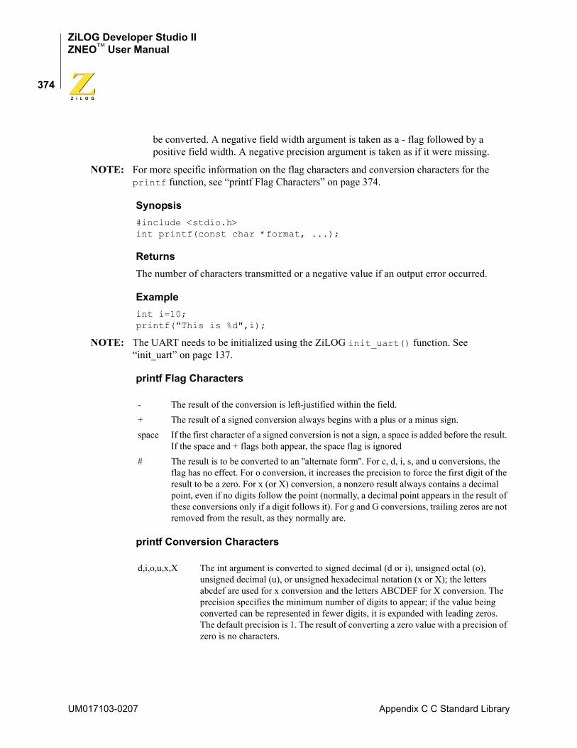
ZiLOG Developer Studio IIZNEO™ User Manual
374
be converted. A negative field width argument is taken as a - flag followed by a positive field width. A negative precision argument is taken as if it were missing.
NOTE: For more specific information on the flag characters and conversion characters for the printf function, see “printf Flag Characters” on page 374.
Synopsis#include <stdio.h> int printf(const char *format, ...);
ReturnsThe number of characters transmitted or a negative value if an output error occurred.
Exampleint i=10; printf("This is %d",i);
NOTE: The UART needs to be initialized using the ZiLOG init_uart() function. See “init_uart” on page 137.
printf Flag Characters
printf Conversion Characters
- The result of the conversion is left-justified within the field.+ The result of a signed conversion always begins with a plus or a minus sign.space If the first character of a signed conversion is not a sign, a space is added before the result.
If the space and + flags both appear, the space flag is ignored# The result is to be converted to an ''alternate form''. For c, d, i, s, and u conversions, the
flag has no effect. For o conversion, it increases the precision to force the first digit of the result to be a zero. For x (or X) conversion, a nonzero result always contains a decimal point, even if no digits follow the point (normally, a decimal point appears in the result of these conversions only if a digit follows it). For g and G conversions, trailing zeros are not removed from the result, as they normally are.
d,i,o,u,x,X The int argument is converted to signed decimal (d or i), unsigned octal (o), unsigned decimal (u), or unsigned hexadecimal notation (x or X); the letters abcdef are used for x conversion and the letters ABCDEF for X conversion. The precision specifies the minimum number of digits to appear; if the value being converted can be represented in fewer digits, it is expanded with leading zeros. The default precision is 1. The result of converting a zero value with a precision of zero is no characters.
UM017103-0207 Appendix C C Standard Library
ZiLOG Developer Studio IIZNEO™ User Manual
375
In no case does a nonexistent or small field width cause truncation of a field. If the result of a conversion is wider than the field width, the field is expanded to contain the conver-sion result.
putcharWrites a character to the serial port.
Synopsis#include <stdio.h> int putchar(int c);
f The double argument is converted to decimal notation in the style [-]ddd.ddd, where the number of digits after the decimal point is equal to the precision specification. If the precision is missing, it is taken as 6; if the precision is explicitly zero, no decimal point appears. If a decimal point appears, at least one digit appears before it. The value is rounded to the appropriate number of digits.
e,E The double argument is converted in the style [-]d.ddde+dd, where there is one digit before the decimal point and the number of digits after it is equal to the precision; when the precision is missing, six digits are produced; if the precision is zero, no decimal point appears. The value is rounded to the appropriate number of digits. The E conversion character produces a number with E instead of e introducing the exponent. The exponent always contains at least two digits. However, if the magnitude to be converted is greater than or equal to lE+100, additional exponent digits are written as necessary.
g,G The double argument is converted in style f or e (or in style E in the case of a G conversion character), with the precision specifying the number of significant digits. The style used depends on the value converted; style e is used only if the exponent resulting from the conversion is less than -4 or greater than the precision. Trailing zeros are removed from the result; a decimal point appears only if it is followed by a digit.
c The int argument is converted to an unsigned char, and the resulting character is written.
s The argument is taken to be a (const char *) pointer to a string. Characters from the string are written up to, but not including, the terminating null character, or until the number of characters indicated by the precision are written. If the precision is missing it is taken to be arbitrarily large, so all characters before the first null character are written.
p The argument is taken to be a (const void) pointer to an object. The value of the pointer is converted to a sequence of hex digits.
n The argument is taken to be an (int) pointer to an integer into which is written the number of characters written to the output stream so far by this call to printf. No argument is converted.
% A % is written. No argument is converted.
Appendix C C Standard Library UM017103-0207
ZiLOG Developer Studio IIZNEO™ User Manual
376
ReturnsThe character written. If a write error occurs, putchar returns EOF.
Exampleint i; charc='a'; i=putchar(c);
NOTE: The UART needs to be initialized using the ZiLOG init_uart() function. See “init_uart” on page 137.
putsWrites the string pointed to by s to the serial port and appends a new-line character to the output. The terminating null character is not written.
Synopsis#include <stdio.h> int puts(char *s);
ReturnsEOF if an error occurs; otherwise, it is a non-negative value.
Exampleint i; char strp[]="COMPASS"; i=puts(str);
NOTE: The UART needs to be initialized using the ZiLOG init_uart() function. See “init_uart” on page 137.
qsortSorts an array of nmemb objects, the initial member of which is pointed to by any base. The size of each object is specified by size.
The array is sorted in ascending order according to a comparison function pointed to by compar, which is called with two arguments that point to the objects being compared. The compar function returns an integer less than, equal to, or greater than zero if the first argu-ment is considered to be respectively less than, equal to, or greater than the second.
If two members in the array compare as equal, their order in the sorted array is unspeci-fied.
Synopsis#include <stdlib.h>
UM017103-0207 Appendix C C Standard Library
ZiLOG Developer Studio IIZNEO™ User Manual
377
void qsort(void *base, size_t nmemb, size_t size, int (*compar)(const void *, const void *));
Exampleint lst[]={5,8,2,9}; int compare (const void * x, const void * y); qsort (lst, sizeof(int), 4, compare);
int compare (const void * x, const void * y){
int a = *(int *) x;int b = *(int *) y;if (a < b) return -1;if (a == b)return 0;return 1;
}
The compare function prototype is, as shown in the preceding example: int compare (const void * x, const void * y);
randComputes a sequence of pseudorandom integers in the range 0 to RAND_MAX.
Synopsis#include <stdlib.h> int rand(void);
ReturnsA pseudorandom integer.
Exampleint i; srand(1001); i=rand();
reallocChanges the size of the object pointed to by ptr to the size specified by size. The contents of the object are unchanged up to the lesser of the new and old sizes. If ptr is a null pointer, the realloc function behaves like the malloc function for the specified size. Otherwise, if ptr does not match a pointer earlier returned by the calloc, malloc, or realloc func-tion, or if the space has been deallocated by a call to the free or realloc function, the behavior is undefined. If the space cannot be allocated, the realloc function returns a null pointer and the object pointed to by ptr is unchanged. If size is zero, the realloc function returns a null pointer and, if ptr is not a null pointer, the object it points to is freed.
Appendix C C Standard Library UM017103-0207
ZiLOG Developer Studio IIZNEO™ User Manual
378
Synopsis#include <stdlib.h> void *realloc(void *ptr, size_t size);
ReturnsReturns a pointer to the start (lowest byte address) of the possibly moved object.
Examplechar *buf; buf=(char *) malloc(40*sizeof(char)); buf=(char *) realloc(buf, 80*sizeof(char)); if(buf !=NULL)
/*success*/ else
/*fail*/
scanfReads input from the stream pointed to by stdin, under control of the string pointed to by format that specifies the admissible input sequences and how they are to be converted for assignment, using subsequent arguments as pointers to the object to receive the converted input. If there are insufficient arguments for the format, the behavior is undefined. If the format is exhausted while arguments remain, the excess arguments are evaluated but otherwise ignored.
The format is composed of zero or more directives from the following list:
• one or more white-space characters
• an ordinary character (not %)
• a conversion specification
Each conversion specification is introduced by the character %. After the %, the following appear in sequence:
• An optional assignment-suppressing character *.
• An optional decimal integer that specifies the maximum field width.
• An optional h, l or L indicating the size of the receiving object. The conversion characters d, l, n, o, and x can be preceded by h to indicate that the corresponding argument is a pointer to short_int rather than a pointer to int, or by l to indicate that it is a pointer to long_int. Similarly, the conversion character u can be preceded by h to indicate that the corresponding argument is a pointer to unsigned_short_int rather than a pointer to unsigned_int, or by l to indicate that it is a pointer to unsigned_long_int. Finally, the conversion character e, f, and g can be preceded by l to indicate that the corresponding argument is a pointer to double rather than a pointer to float, or by L to
UM017103-0207 Appendix C C Standard Library
ZiLOG Developer Studio IIZNEO™ User Manual
379
indicate a pointer to long_double. If an h, l, or L appears with any other conversion character, it is ignored.
• A character that specifies the type of conversion to be applied. The valid conversion characters are described in the following paragraphs.
The scanf function executes each directive of the format in turn. If a directive fails, as detailed below, the scanf function returns. Failures are described as input failures (due to the unavailability of input characters), or matching failures (due to inappropriate input).
A directive composed of white space is executed by reading input up to the first non-white-space character (which remains unread), or until no more characters can be read. A white-space directive fails if no white-space character can be found.
A directive that is an ordinary character is executed by reading the next character of the stream. If the character differs from the one comprising the directive, the directive fails, and the character remains unread.
A directive that is a conversion specification defines a set of matching input sequences, as described below for each character. A conversion specification is executed in the follow-ing steps:
• Input white-space characters (as specified by the isspace function) are skipped, unless the specification includes a ’[’, ’c,’ or ’n’ character.
• An input item is read from the stream, unless the specification includes an n character. An input item is defined as the longest sequence of input characters (up to any specified maximum field width) which is an initial subsequence of a matching sequence. The first character, if any, after the input item remains unread. If the length of the input item is zero, the execution of the directive fails: this condition is a matching failure, unless an error prevented input from the stream, in which case it is an input failure.
• Except in the case of a % character, the input item (or, in the case of a %n directive, the count of input characters) is converted to a type appropriate to the conversion character. If the input item is not a matching sequence, the execution of the directive fails: this condition is a matching failure. Unless assignment suppression was indicated by a *, the result of the conversion is placed in the object pointed to by the first argument following the format argument that has not already received a conversion result. If this object does not have an appropriate type, or if the result of the conversion cannot be represented in the space provided, the behavior is undefined.
NOTE: See “scanf Conversion Characters” for valid input information.
Synopsis#include <stdio.h> int scanf(const char *format, ...);
Appendix C C Standard Library UM017103-0207
ZiLOG Developer Studio IIZNEO™ User Manual
380
ReturnsThe value of the macro EOF if an input failure occurs before any conversion. Otherwise, the scanf function returns the number of input items assigned, which can be fewer than provided for, or even zero, in the event of an early conflict between an input character and the format.
Examplesint i scanf("%d", &i);
The following example reads in two values. var1 is an unsigned char with two decimal digits, and var2 is a float with three decimal place precision.scanf("%2d,%f",&var1,&var2);
scanf Conversion Characters
d Matches an optionally signed decimal integer, whose format is the same as expected for the subject sequence of the strtol function with the value 10 for the base argument. The corresponding argument is a pointer to integer.
i Matches an optionally signed integer, whose format is the same as expected for the subject sequence of the strtol function with the value 0 for the base argument. The corresponding argument is a pointer to integer.
o Matches an optionally signed octal integer, whose format is the same as expected for the subject sequence of the strtol function with the value 8 for the base argument. The corresponding argument is a pointer to integer.
u Matches an unsigned decimal integer, whose format is the same as expected for the subject sequence of the strtol function with the value 10 for the base argument. The corresponding argument is a pointer to unsigned integer.
x Matches an optionally signed hexadecimal integer, whose format is the same as expected for the subject sequence of the strtol function with the value of 16 for the base argument. The corresponding argument is a pointer to integer.
e,f,g Matches an optionally signed floating-point number, whose format is the same as expected for the subject string of the strtod function. The corresponding argument is a pointer to floating.
s Matches a sequence of non-white-space characters. The corresponding argument is a pointer to the initial character of an array large enough to accept the sequence and a terminating null character, which is added automatically.
UM017103-0207 Appendix C C Standard Library
ZiLOG Developer Studio IIZNEO™ User Manual
381
If a conversion specification is invalid, the behavior is undefined.
The conversion characters e, g, and x can be capitalized. However, the use of upper case is ignored.
If end-of-file is encountered during input, conversion is terminated. If end-of-file occurs before any characters matching the current directive have been read (other than leading white space, where permitted), execution of the current directive terminates with an input failure; otherwise, unless execution of the current directive is terminated with a matching failure, execution of the following directive (if any) is terminated with an input failure.
If conversion terminates on a conflicting input character, the offending input character is left unread in the input stream. Trailing white space (including new-line characters) is left unread unless matched by a directive. The success of literal matches and suppressed assignments is not directly determinable other than using the %n directive.
setjmpSaves its calling environment in its jmp_buf argument, for later use by the longjmp function.
Synopsis#include<setjmp.h> int setjmp(jmp_buf env);
[ Matches a sequence of expected characters (the scanset). The corresponding argument is a pointer to the initial character of an array large enough to accept the sequence and a terminating null character, which is added automatically. The conversion character includes all subsequent characters is the format string, up to and including the matching right bracket ( ] ). The characters between the brackets (the scanlist) comprise the scanset, unless the character after the left bracket is a circumflex ( ^ ), in which case the scanset contains all characters that do not appear in the scanlist between the circumflex and the right bracket. As a special case, if the conversion character begins with [] or [^], the right bracket character is in the scanlist and next right bracket character is the matching right bracket that ends the specification. If a - character is in the scanlist and is neither the first nor the last character, the behavior is indeterminate.
c Matches a sequence of characters of the number specified by the field width (1 if no field width is present in the directive). The corresponding argument is a pointer to the initial character of an array large enough to accept the sequence. No null character is added.
p Matches a hexadecimal number. The corresponding argument is a pointer to a pointer to void.
n No input is consumed. The corresponding argument is a pointer to integer into which is to be written the number of characters read from the input stream so far by this call to the scanf function. Execution of a %n directive does not increment the assignment count returned at the completion of execution of the scanf function.
% Matches a single %; no conversion or assignment occurs.
Appendix C C Standard Library UM017103-0207
ZiLOG Developer Studio IIZNEO™ User Manual
382
ReturnsIf the return is from a direct invocation, the setjmp function returns the value zero. If the return is from a call to the longjmp function, the setjmp function returns a nonzero value.
Exampleint i; jmp_buf env; i=setjmp(env); longjmp(env, i);
sin, sinfComputes the sine of x (measured in radians). A large magnitude argument can yield a result with little or no significance.
Synopsis#include <math.h> double sin(double x); float sinf(float x);
ReturnsThe sine value.
Exampledouble x=1.24; double y; y=sin(x);
sinh, sinhfComputes the hyperbolic sine of x. A range error occurs if the magnitude of x is too large.
Synopsis#include <math.h> double sinh(double x); float sinhf(float x);
ReturnsThe hyperbolic sine value.
UM017103-0207 Appendix C C Standard Library
ZiLOG Developer Studio IIZNEO™ User Manual
383
Exampledouble x=1.24; double y; y=sinh(x);
sprintfThe sprintf function is equivalent to printf, except that the argument s specifies an array into which the generated output is to be written, rather than to a stream. A null char-acter is written at the end of the characters written; it is not counted as part of the returned sum.
Synopsis#include <stdio.h> int sprintf(char *s, const char *format, ...);
ReturnsThe number of characters written in the array, not counting the terminating null character.
Exampleint d=51; char buf [40]; sprintf(buf,"COMPASS/%d",d);
sqrt, sqrtfComputes the non-negative square root of x. A domain error occurs if the argument is negative.
Synopsis#include <math.h> double sqrt(double x); float sqrtf(float x);
ReturnsThe value of the square root.
Exampledouble x=25.0; double y; y=sqrt(x);
Appendix C C Standard Library UM017103-0207
ZiLOG Developer Studio IIZNEO™ User Manual
384
srandUses the argument as a seed for a new sequence of pseudorandom numbers to be returned by subsequent calls to rand. If srand is then called with the same seed value, the sequence of pseudorandom numbers is repeated. If rand is called before any calls to srand have been made, the same sequence is generated as when srand is first called with a seed value of 1.
Synopsis#include <stdlib.h> void srand(unsigned int seed);
Exampleint i; srand(1001); i=rand();
sscanfReads formatted data from a string.
Synopsis#include <stdio.h> int sscanf(const char *s, const char *format, ...);
ReturnsThe value of the macro EOF if an input failure occurs before any conversion. Otherwise, the sscanf function returns the number of input items assigned, which can be fewer than provided for, or even zero, in the event of an early conflict between an input character and the format.
Examplechar buf [80]; int i; sscanf(buf,"%d",&i);
strcatAppends a copy of the string pointed to by s2 (including the terminating null character) to the end of the string pointed to by s1. The initial character of s2 overwrites the null charac-ter at the end of s1.
UM017103-0207 Appendix C C Standard Library
ZiLOG Developer Studio IIZNEO™ User Manual
385
Synopsis#include <string.h> char *strcat(char *s1, const char *s2);
ReturnsThe value of s1.
Examplechar *ptr; char s1[80]="Production"; char s2[]="Languages"; ptr=strcat(s1,s2);
strchrLocates the first occurrence of c (converted to a char) in the string pointed to by s. The terminating null character is considered to be part of the string.
Synopsis#include <string.h> char *strchr(const char *s, int c);
ReturnsA pointer to the located character or a null pointer if the character does not occur in the string.
Examplechar *ptr; char str[]="COMPASS"; ptr=strchr(str,'p');
strcmpCompares the string pointed to by s1 to the string pointed to by s2.
Synopsis#include <string.h> int strcmp(const char *s1, const char *s2);
ReturnsAn integer greater than, equal to, or less than zero, according as the string pointed to by s1 is greater than, equal to, or less than the string pointed to by s2.
Appendix C C Standard Library UM017103-0207
ZiLOG Developer Studio IIZNEO™ User Manual
386
Examplechar s1[]="Production"; char s2[]="Programming"; int res; res=strcmp(s1,s2);
strcpyCopies the string pointed to by s2 (including the terminating null character) into the array pointed to by s1. If copying takes place between objects that overlap, the behavior is unde-fined.
Synopsis#include <string.h> char *strcpy(char *s1, const char *s2);
ReturnsThe value of s1.
Examplechar s1[80], *s2; s2=strcpy(s1,"Production");
strcspnComputes the length of the initial segment of the string pointed to by s1 that consists entirely of characters not from the string pointed to by s2. The terminating null character is not considered part of s2.
Synopsis#include <string.h> size_t strcspn(const char *s1, const char *s2);
ReturnsThe length of the segment.
Examplesize_t pos; char s1[]="xyzabc"; char s2[]="abc"; pos=strcspn(s1,s2);
UM017103-0207 Appendix C C Standard Library
ZiLOG Developer Studio IIZNEO™ User Manual
387
strlenComputes the length of the string pointed to by s.
Synopsis#include <string.h> size_t strlen(const char *s);
ReturnsThe number of characters that precede the terminating null character.
Examplechar s1[]="COMPASS"; size_t i; i=strlen(s1);
strncatAppends no more than n characters of the string pointed to by s2 (not including the termi-nating null character) to the end of the string pointed to by s1. The initial character of s2 overwrites the null character at the end of s1. A terminating null character is always appended to the result.
Synopsis#include <string.h> char *strncat(char *s1, const char *s2, size_t n);
ReturnsThe value of s1.
Examplechar *ptr; char strl[80]="Production"; char str2[]="Languages"; ptr=strncat(str1,str2,4);
strncmpCompares no more than n characters from the string pointed to by s1 to the string pointed to by s2.
Synopsis#include <string.h> int strncmp(const char *s1, const char *s2, size_t n);
Appendix C C Standard Library UM017103-0207
ZiLOG Developer Studio IIZNEO™ User Manual
388
ReturnsAn integer greater than, equal to, or less than zero, according as the string pointed to by s1 is greater than, equal to, or less than the string pointed to by s2.
Examplechar s1[]="Production"; char s2[]="Programming"; int res; res=strncmp(s1,s2,3);
strncpyCopies not more than n characters from the string pointed to by s2 to the array pointed to by s1. If copying takes place between objects that overlap, the behavior is undefined.
If the string pointed to by s2 is shorter than n characters, null characters are appended to the copy in the array pointed to by s1, until n characters in all have been written.
Synopsis#include <string.h> char *strncpy(char *s1, const char *s2, size_t n);
ReturnsThe value of s1.
Examplechar *ptr; char s1[40]="Production"; char s2[]="Languages"; ptr=strncpy(s1,s2,4);
strpbrkLocates the first occurrence in the string pointed to by s1 of any character from the string pointed to by s2.
Synopsis#include <string.h> char *strpbrk(const char *s1, const char *s2);
ReturnsA pointer to the character, or a null pointer if no character from s2 occurs in s1.
UM017103-0207 Appendix C C Standard Library
ZiLOG Developer Studio IIZNEO™ User Manual
389
Examplechar *ptr; char s1[]="COMPASS"; char s2[]="PASS"; ptr=strpbrk(s1,s2);
strrchrLocates the last occurrence of c (converted to a char) in the string pointed to by s. The terminating null character is considered to be part of the string.
Synopsis#include <string.h> char *strrchr(const char *s, int c);
ReturnsA pointer to the character, or a null pointer if c does not occur in the string.
Examplechar *ptr; char s1[]="COMPASS"; ptr=strrchr(s1,'p');
strspnFinds the first substring from a given character set in a string.
Synopsis#include <string.h> size_t strspn(const char *s1, const char *s2);
ReturnsThe length of the segment.
Examplechar s1[]="cabbage"; char s2[]="abc"; size_t res, res=strspn(s1,s2);
Appendix C C Standard Library UM017103-0207
ZiLOG Developer Studio IIZNEO™ User Manual
390
strstrLocates the first occurrence of the string pointed to by s2 in the string pointed to by s1.
Synopsis#include <string.h> char *strstr(const char *s1, const char *s2);
ReturnsA pointer to the located string or a null pointer if the string is not found.
Examplechar *ptr; char s1[]="Production Languages"; char s2[]="Lang"; ptr=strstr(s1,s2);
strtod, strtofConverts the string pointed to by nptr to double (strtod) or float (strtof) represen-tation. The function recognizes an optional leading sequence of white-space characters (as specified by the isspace function), then an optional plus or minus sign, then a sequence of digits optionally containing a decimal point, then an optional letter e or E followed by an optionally signed integer, then an optional floating suffix. If an inappropriate character occurs before the first digit following the e or E, the exponent is taken to be zero.The first inappropriate character ends the conversion. If endptr is not a null pointer, a pointer to that character is stored in the object endptr points to; if an inappropriate charac-ter occurs before any digit, the value of nptr is stored.The sequence of characters from the first digit or the decimal point (whichever occurs first) to the character before the first inappropriate character is interpreted as a floating constant according to the rules of this section, except that if neither an exponent part or a decimal point appears, a decimal point is assumed to follow the last digit in the string. If a minus sign appears immediately before the first digit, the value resulting from the conver-sion is negated.
Synopsis#include <stdlib.h> double strtod(const char *nptr, char **endptr); float strtof(const char *nptr, char **endptr);
ReturnsThe converted value, or zero if an inappropriate character occurs before any digit. If the correct value would cause overflow, plus or minus HUGE_VAL is returned (according to the sign of the value), and the macro errno acquires the value ERANGE. If the correct
UM017103-0207 Appendix C C Standard Library
ZiLOG Developer Studio IIZNEO™ User Manual
391
value causes underflow, zero is returned and the macro errno acquires the value ERANGE.
Examplechar *ptr; char s[]="0.1456"; double res; res=strtod(s,&ptr);
strtokA sequence of calls to the strtok function breaks the string pointed to by s1 into a sequence of tokens, each of which is delimited by a character from the string pointed to by s2. The first call in the sequence has s1 as its first argument, and is followed by calls with a null pointer as their first argument. The separator string pointed to by s2 can be different from call to call.
The first call in the sequence searches s1 for the first character that is not contained in the current separator string s2. If no such character is found, there are no tokens in s1, and the strtok function returns a null pointer. If such a character is found, it is the start of the first token.
The strtok function then searches from there for a character that is contained in the cur-rent separator string. If no such character is found, the current token extends to the end of the string pointed to by s1, and subsequent searches for a token fail. If such a character is found, it is overwritten by a null character, which terminates the current token. The strtok function saves a pointer to the following character, from which the next search for a token starts.
Each subsequent call, with a null pointer as the value of the first argument, starts searching from the saved pointer and behaves as described in the preceding paragraphs.
Synopsis#include <string.h> char *strtok(char *s1, const char *s2);
ReturnsA pointer to the first character of a token or a null pointer if there is no token.
Example#include <string.h> static char str[] = "?a???b, , ,#c"; char *t; t = strtok(str,"?"); /* t points to the token "a" */ t = strtok(NULL,","); /* t points to the token "??b " */
Appendix C C Standard Library UM017103-0207
ZiLOG Developer Studio IIZNEO™ User Manual
392
t = strtok(NULL,"#,"); /* t points to the token "c" */ t = strtok(NULL,"?"); /* t is a null pointer */
strtolConverts the string pointed to by nptr to long int representation. The function recognizes an optional leading sequence of white-space characters (as specified by the isspace func-tion), then an optional plus or minus sign, then a sequence of digits and letters, then an optional integer suffix.
The first inappropriate character ends the conversion. If endptr is not a null pointer, a pointer to that character is stored in the object endptr points to; if an inappropriate charac-ter occurs before the first digit or recognized letter, the value of nptr is stored.
If the value of base is 0, the sequence of characters from the first digit to the character before the first inappropriate character is interpreted as an integer constant according to the rules of this section. If a minus sign appears immediately before the first digit, the value resulting from the conversion is negated.
If the value of base is between 2 and 36, it is used as the base for conversion. Letters from a (or A) through z (or Z) are ascribed the values 10 to 35; a letter whose value is greater than or equal to the value of base ends the conversion. Leading zeros after the optional sign are ignored, and leading 0x or 0X is ignored if the value of base is 16. If a minus sign appears immediately before the first digit or letter, the value resulting from the conversion is negated.
Synopsis#include <stdlib.h> long strtol(const char *nptr, char **endptr, int base);
ReturnsThe converted value, or zero if an inappropriate character occurs before the first digit or recognized letter. If the correct value would cause overflow, LONG_MAX or LONG_MIN is returned (according to the sign of the value), and the macro errno acquires the value ERANGE.
Examplechar *ptr; char s[]="12345"; long res; res=strtol(s,&ptr,10);
UM017103-0207 Appendix C C Standard Library
ZiLOG Developer Studio IIZNEO™ User Manual
393
tan, tanfThe tangent of x (measured in radians). A large magnitude argument can yield a result with little or no significance.
Synopsis#include <math.h> double tan(double x); float tanf(float x);
ReturnsThe tangent value.
Exampledouble x=2.22; double y; y=tan(x);
tanh, tanhfComputes the hyperbolic tangent of x.
Synopsis#include <math.h> double tanh(double x); float tanhf(float x);
ReturnsThe hyperbolic tangent of x.
Exampledouble x=2.22; double y; y=tanh(x);
tolowerConverts an uppercase letter to the corresponding lowercase letter.
Synopsis#include <ctype.h> int tolower(int c);
Appendix C C Standard Library UM017103-0207
ZiLOG Developer Studio IIZNEO™ User Manual
394
ReturnsIf the argument is an uppercase letter, the tolower function returns the corresponding lowercase letter, if any; otherwise, the argument is returned unchanged.
Examplechar c='A'; int i; i=tolower(c);
toupperConverts a lowercase letter to the corresponding uppercase letter.
Synopsis#include <ctype.h> int toupper(int c);
ReturnsIf the argument is a lowercase letter, the toupper function returns the corresponding uppercase letter, if any; otherwise, the argument is returned unchanged.
Examplechar c='a'; int i; i=toupper(c);
va_argExpands to an expression that has the type and value of the next argument in the call. The parameter ap is the same as the va_list ap initialized by va_start. Each invocation of va_arg modifies ap so that successive arguments are returned in turn. The parameter type is a type name such that the type of a pointer to an object that has the specified type can be obtained simply by fixing a * to type. If type disagrees with the type of the actual next argument (as promoted, according to the default argument conversions, into int, unsigned int, or double), the behavior is undefined.
Synopsis
#include <stdarg.h> type va_arg(va_list ap, type);
UM017103-0207 Appendix C C Standard Library
ZiLOG Developer Studio IIZNEO™ User Manual
395
ReturnsThe first invocation of the va_arg macro after that of the va_start macro returns the value of the argument after that specified by parmN. Successive invocations return the val-ues of the remaining arguments in succession.
ExampleThe function f1 gathers into an array a list of arguments that are pointers to strings (but not more than MAXARGS arguments), then passes the array as a single argument to function f2. The number of pointers is specified by the first argument to f1.#include <stdarg.h>extern void f2(int n, char *array[]);#define MAXARGS 31 void f1(int n_ptrs,...) {
va_list ap; char *array[MAXARGS]; int ptr_no = 0;
if (n_ptrs > MAXARGS) n_ptrs = MAXARGS;
va_start(ap, n_ptrs);while (ptr_no < n_ptrs)
array[ptr_no++] = va_arg(ap, char *);va_end(ap); f2(n_ptrs, array);
}
Each call to f1 has in scope the definition of the function of a declaration such as void f1(int, ...);
va_endFacilitates a normal return from the function whose variable argument list was referenced by the expansion of va_start that initialized the va_list ap. The va_end function can modify ap so that it is no longer usable (without an intervening invocation of va_start). If the va_end function is not invoked before the return, the behavior is unde-fined.
Synopsis#include <stdarg.h> void va_end(va_list ap);
ExampleThe function f1 gathers into an array a list of arguments that are pointers to strings (but not more than MAXARGS arguments), then passes the array as a single argument to function f2. The number of pointers is specified by the first argument to f1.
Appendix C C Standard Library UM017103-0207
ZiLOG Developer Studio IIZNEO™ User Manual
396
#include <stdarg.h>extern void f2(int n, char *array[]);#define MAXARGS 31 void f1(int n_ptrs,...) {
va_list ap; char *array[MAXARGS]; int ptr_no = 0;
if (n_ptrs > MAXARGS) n_ptrs = MAXARGS;
va_start(ap, n_ptrs);while (ptr_no < n_ptrs)
array[ptr_no++] = va_arg(ap, char *);va_end(ap); f2(n_ptrs, array);
}
Each call to f1 has in scope the definition of the function of a declaration such as void f1(int, ...);
va_startIs executed before any access to the unnamed arguments.
The parameter ap points to an object that has type va_list. The parameter parmN is the identifier of the rightmost parameter in the variable parameter list in the function defini-tion (the one just before the , ...). The va_start macro initializes ap for subsequent use by va_arg and va_end.
Synopsis#include <stdarg.h> void va_start(va_list ap, parmN);
ExampleThe function f1 gathers into an array a list of arguments that are pointers to strings (but not more than MAXARGS arguments), then passes the array as a single argument to function f2. The number of pointers is specified by the first argument to f1.#include <stdarg.h>extern void f2(int n, char *array[]);#define MAXARGS 31 void f1(int n_ptrs,...) {
va_list ap; char *array[MAXARGS]; int ptr_no = 0;
if (n_ptrs > MAXARGS) n_ptrs = MAXARGS;
UM017103-0207 Appendix C C Standard Library
ZiLOG Developer Studio IIZNEO™ User Manual
397
va_start(ap, n_ptrs);while (ptr_no < n_ptrs)
array[ptr_no++] = va_arg(ap, char *);va_end(ap); f2(n_ptrs, array);
}
Each call to f1 has in scope the definition of the function of a declaration such as void f1(int, ...);
vprintfEquivalent to printf, with the variable argument list replaced by arg, which has been ini-tialized by the va_start macro (and possibly subsequent va_arg calls). The vprintf function does not invoke the va_end function.
Synopsis#include <stdarg.h> #include <stdio.h> int vprintf(const char *format, va_list arg);
ReturnsThe number of characters transmitted or a negative value if an output error occurred.
Exampleva_list va; /* initialize the variable argument va here */ vprintf("%d %d %d",va);
vsprintfEquivalent to sprintf, with the variable argument list replaced by arg, which has been initialized by the va_start macro (and possibly subsequent va_arg calls). The vsprintf function does not invoke the va_end function.
Synopsis#include <stdarg.h> #include <stdio.h> int vsprintf(char *s, const char *format, va_list arg);
ReturnsThe number of characters written in the array, not counting the terminating null character.
Appendix C C Standard Library UM017103-0207
ZiLOG Developer Studio IIZNEO™ User Manual
398
Exampleva_list va; char buf[80]; /*initialize the variable argument va here*/ vsprint(buf, "%d %d %d",va);
UM017103-0207 Appendix C C Standard Library
ZiLOG Developer Studio IIZNEO™ User Manual
399
Glossary
AABS. Absolute Value.A/D. Analog-to-Digital—the conversion of an analog signal, such as a waveform, to a digital signal, represented by binary data. See ADC.ADC. Analog-to-Digital Converter—a circuit that converts an analog signal to a digital bit stream. See A/D.address space. The physical or logical area of the target system’s memory map. The memory map could be physically partitioned into ROM to store code, and RAM for data. The memory can also be divided logically to form separate areas for code and data storage.ALU. See Arithmetic Logical Unit.American National Standards Institute (ANSI). The U.S. standards organization that establishes procedures for the development and coordination of voluntary American National Standards.analog. From the word analogous, meaning similar to. The signal being transmitted can be represented in a way similar to the original signal. For example, a telephone signal can be seen on an oscilloscope as a sine wave similar to the voice signal being carried through the phone line.analog signal. A signal that exhibits a continuous nature rather than a pulsed or discrete nature. AND. A bitwise AND instruction.ANSI. American National Standards Institute.application program interface (API). A formalized set of software calls and routines that can be referenced by an application program to access supporting network services.architecture. Of a computer, the physical configuration, logical structure, formats, protocols, and operational sequences for processing data, controlling the configuration, and controlling the operations. Computer architecture may also include word lengths, instruction codes, and the interrelationships among the main parts of a computer or group of computers.Arithmetic Logical Unit (ALU). the element that can perform the basic data manipulations in the central processor. Usually, the ALU can add, subtract, complement, negate, rotate, AND, and OR.array. 1. An arrangement of elements in one or more dimensions. 2. In a programming language, an aggregate that consists of data objects with identical attributes, each of which may be uniquely referenced by subscription.ASCII. Acronym for American Standard Code for Information Interchange. The standard code used for information interchange among data processing systems, data communications systems, and associated equipment in the United States. ASM. Assembler File.assembly. 1. The manufacturing process that converts circuits in wafer form into finished packaged parts. 2. A short term for assembly language.
Glossary UM017103-0207
ZiLOG Developer Studio IIZNEO™ User Manual
400
Bbaud. A unit of measure of transmission capacity. The speed at which a modem can transmit data. The number of events or signal changes that occur in one second. Because one event can encode more than one bit in high-speed digital communications, baud rate and bits per second are not always synonymous, especially at speeds above 2400 bps.baud rate. A unit of measure of the number of state changes (from 0 to 1 or 1 to 0) per second on an asynchronous communications channel.binary (b). A number system based on 2. A binary digit is a bit.bit. binary digit—a digit of a binary system. It contains only two possible values: 0 or 1.block diagram. A diagram of a system, a computer, or a device in which the principal parts are represented by suitably annotated geometrical figures to show both the basic functions of the parts and their functional relationships.buffer. 1. In hardware, a device that restores logic drive signal levels to drive a bus or a large number of inputs. In software, any memory structure allocated to the temporary storage of data. 2. A routine or storage medium used to compensate for a difference in rate of flow of data, or time of occurrence of events, when transferring data from one device to another. bus. In electronics, a parallel interconnection of the internal units of a system that enables data transfer and control information. One or more conductors or optical fibers that serve as a common connection for a group of related devices. byte (B). A sequence of adjacent bits (usually 8) considered as a unit. A collection of four sequential bits of memory. Two sequential bytes (8 bits) comprise one word.
CCALL. This command invokes a subroutine.CCF. Clear Carry Flag.character set. A finite set of different characters that is complete for a given purpose. A character set might include punctuation marks or other symbols. CIEF. Clear IE Flag.clock. A specific cycle designed to time events, used to synchronize events in a system.CLR. Clear.CMOS. Complementary Metal Oxide Semiconductor. A type of integrated circuit used in processors and for memory.compile. 1. To translate a computer program expressed in a high-level language into a program expressed in a lower level language, such as an intermediate language, assembly language, or a machine language. 2. To prepare a machine language program from a computer program written in another programming language by making use of the overall logic structure of the program or by generating more than one computer instruction for each symbolic statement as well as performing the function of an assembler.compiler. A computer program for compiling. COPF. Clear Overflow Protection Flag.
UM017103-0207 Glossary
ZiLOG Developer Studio IIZNEO™ User Manual
401
CPU. Abbreviation for Central Processing Unit. 1. The portion of a computer that includes circuits controlling the interpretation and execution of instructions. 2. The portion of a computer that executes programmed instructions, performs arithmetic and logical operations on data, and controls input/output functions.
Ddebug. To detect, trace, and eliminate mistakes. DI. Disable interrupt.
EEI. Enable interrupt.emulation. The process of duplicating the characteristics of one product or part using another medium. For example, an In-Circuit Emulator (ICE) module duplicates the behavior of the chip it emulates, in the circuit being tested.emulator. An emulation device. EOF. End of file—when all records in a file are processed, the computer encounters an end-of-file condition.EPROM. Erasable Programmable Read-Only Memory. An EPROM can be erased by exposure to ultraviolet light.EQ. A Boolean operator meaning Equal to.escape sequence. A special escape command is entered as three plus symbols (+++). placing the modem in command mode, and interrupting user data transmission. However, the escape sequence does not terminate the data connection. Command mode allows the entering of commands while the connection is maintained.
FF. Falling Edge. Fast Fourier Transform. An algorithm for computing the Fourier transform of a set of discrete data values. Given a finite set of data points—for example, a periodic sampling taken from a real-world signal—the FFT expresses the data in terms of its component frequencies. It also solves the essentially identical inverse problem of reconstructing a signal from the frequency data.FFT. See Fast Fourier Transform.filter. A process for removing information content, such as high or low frequencies.flag. In data transmission or processing, an indicator, such as a signal, symbol, character, or digit, used for identification. A flag may be a byte, word, mark, group mark, or letter that signals the occurrence of some condition or event, such as the end of a word, block, or message.frequency. For a periodic function, the number of cycles or events per unit time.
Glossary UM017103-0207
ZiLOG Developer Studio IIZNEO™ User Manual
402
Ggraphical user interface (GUI). 1. A graphics-based user interface that enables users to select files, programs or commands by pointing to pictorial representations (icons) on the screen, rather than by typing long, complex commands from a command prompt. 2. The windows and incorporated text displayed on a computer screen.groups. Collections of logical address spaces typically used for convenience of locating a set of address spaces.GUI. See graphical user interface.
Hh. See hexadecimal.hardware. The boards, wires, and devices that comprise the physical components of a system.Hertz. Abbreviated Hz. A measurement of frequency in cycles per second. A hertz is one cycle per second. A kilohertz (KHz) is one thousand cycles per second. A megahertz (MHz) is one million cycles per second. A gigahertz (GHz) is a billion cycles per second.hexadecimal. A base-16 number system. Hex values are often substituted for harder-to-read binary numbers.
IICE. In-Circuit Emulator. A ZiLOG product that supports the application design process.icon. A small screen image representing a specific element like a document, embedded and linked objects, or a collection of programs gathered together in a group.ID. Identifier.IE. Interrupt Enable.initialize. To establish start-up parameters, typically involving clearing all of some part of the device’s memory space.instruction. Command.interface (I/F). 1. In a system, a shared boundary, i.e., the boundary between two subsystems or two devices. 2. A shared boundary between two functional units, defined by specific attributes, such as functional characteristics, common physical interconnection characteristics, and signal characteristics. 3. A point of communication between two or more processes, persons, or other physical entities. interleaving. The transmission of pulses from two or more digital sources in time-division sequence over a single path. interrupt. A suspension of a process, such as the execution of a computer program, caused by an event external to that process, and performed in such a way that the process can be resumed. The three types of interrupts include: internal hardware, external hardware, and software.I/O. Input/Output. In computers, the part of the system that deals with interfacing to external devices for input or output, such as keyboards or printers.
UM017103-0207 Glossary
ZiLOG Developer Studio IIZNEO™ User Manual
403
IPR. Interrupt Priority Register.
JJP. Jump.
KK. Thousands. May indicate 1000 or 1024 to differentiate between decimal and binary values. Abbreviation for the Latin root kilo.kHz. See kilohertz.kilohertz (kHz). A unit of frequency denoting one thousand (103) Hz.
LLD. Load.library. A file that contains a collection of object modules that were created by an assembler or directly by a C compiler.LSB. Least significant bit.
MMAC. An acronym for Media Access Control, the method a computer uses to transmit or receive data across a LAN.Megahertz (MHz). A unit of frequency denoting one million (106) Hz. memory. 1. All of the addressable storage space in a processing unit and other internal memory that is used to execute instructions. 2. The volatile, main storage in computers. MHz. See Megahertz; also Hertz.MI. Minus.MLD. Multiply and Load.MPYA. Multiply and Add.MPYS. Multiply and Subtract.MSB. Most significant bit.
Nn. Number. This letter is used as place holder notation.NC. No Connection.NE. Not Equal.
Glossary UM017103-0207
ZiLOG Developer Studio IIZNEO™ User Manual
404
NEG. Negate.NMI. Nonmaskable interrupt.NOP. An acronym for No Operation, an instruction whose sole function is to increment the program counter, but that does not affect any changes to registers or memory.
OOp Code. Operation Code, a quantity that is altered by a microprocessor’s instruction. Also abbreviated OPC.OR. Bitwise OR.OV. Overflow.
PPC. Program counter.pipeline. The act of initiating a bus cycle while another bus cycle is in progress. Thus, the bus can have multiple bus cycles pending at a time.POP. Retrieve a value from the stack.port. The point at which a communications circuit terminates at a network, serial, or parallel interface card.power. The rate of transfer or absorption of energy per unit time in a system. push. To store a value in the stack.
RRAM. Random-access memory. A memory that can be written to or read at random. The device is usually volatile, which means the data is lost without power.random-access memory (RAM). A read/write, nonsequential-access memory used for the storage of instructions and data. read-only memory (ROM). A type of memory in which data, under normal conditions, can only be read. Nonvolatile computer memory that contains instructions that do not require change, such as permanent parts of an operating system. A computer can read instructions from ROM, but cannot store new data in ROM. Also called nonerasable storage.register. A device, accessible to one or more input circuits, that accepts and stores data. A register is most often used only as a device for temporary storage of data. ROM. See read-only memory.RR. Rotate Right.
UM017103-0207 Glossary
ZiLOG Developer Studio IIZNEO™ User Manual
405
SSCF. Set C Flag.SL. Shift Left.SLL. Shift Left Logical.SP. Stack Pointer.SR. Shift Right.SRA. Shift Right Arithmetic.Static. Characteristic of random-access memory that enables it to operate without clocking signals.SUB. Subtract.
Ttristate. A form of transistor-to-transistor logic in which output stages, or input and output stages, can assume three states. Two are normal low-impedance 1 and 0 states; the third is a high-impedance state that allows many tristate devices to time-share bus lines. This industry term is not trademarked, and is available for ZiLOG use. Do not use 3-state or three-state.
UULT. Unsigned Less Than.
Wwait state. A clock cycle during which no instructions are executed because the processor is waiting for data from memory.word. Amount of data a processor can hold in its registers and process at one time.write. To make a permanent or transient recording of data in a storage device or on a data medium.
XX. 1. Indexed Address. 2. An undefined or indeterminate variable.XOR. Bitwise exclusive OR.
ZZ. 1. Zero. 2. Zero Flag.ZDS. ZiLOG Developer Studio. ZiLOG’s program development environment for Microsoft Windows.
Glossary UM017103-0207

ZiLOG Developer Studio IIZNEO™ User Manual
406
UM017103-0207 Glossary
ZiLOG Developer Studio IIZNEO™ User Manual
407
Index
Symbols# Bytes drop-down list box 97, 98#include 60, 62, 338#pragma asm 123#pragma interrupt 120$$ 202& (and) 227* (multiply) 230+ (add) 227.COMMENT directive 182.ENDSTRUCT directive 193.ENDWITH directive 196.hex file extension 80.map file extension 220, 247.SHORT_STACK_FRAME directive 189.STRUCT directive 193.TAG directive 194.UNION directive 196.WITH directive 196/ (divide) 228<< (shift left) 231<assert.h> header 340<ctype.h> header 340<errno.h> header 339<float.h> header 342<limits.h> header 341<math.h> header 343<outputfile>=<module list> command 216<setjmp.h> header 346<sio.h> header 135<stdarg.h> header 346<stddef.h> header 339<stdio.h> header 347<stdlib.h> header 348<string.h> header 350<zneo.h> header 134>> (shift right) 231
?, script file commandfor expressions 318for variables 319
^ (bitwise exclusive or) 232_ (underscore)
for assembly routine names 131for external identifiers 134for macro names 134
__CONST_IN_ROM__ 127__DATE__ 127__FILE__ 127__LINE__ 127__MODEL__ 127__STDC__ 127__TIME__ 127__UNSIGNED_CHARS__ 127__VECTORS segment 169__ZDATE__ 127__ZILOG__ 127__ZNEO__ 127_Align keyword 122_At keyword
placement of a variable 121placement of consecutive variables 121
_Erom 116_Far 117_far_heapbot 147_far_heaptop 147_far_stack 147_len_farbss 147_len_fardata 147_len_nearbss 147_len_neardata 147_low_far_romdata 147_low_farbss 147_low_fardata 147_low_near_romdata 147
UM017103-0207 Index
ZiLOG Developer Studio IIZNEO™ User Manual
408
_low_nearbss 147_low_neardata 147_Near 116_near_heapbot 147_near_heaptop 147_near_stack 147_Rom 116_SYS_CLK_FREQ 147_SYS_CLK_SRC 147_VECTOR segment 144| (or) 231~ (not) 232
Numerics16 Bit Data Width check box 83
Aabs function 350, 352Absolute segments 170, 186
definition 168, 214locating 220
Absolute value, computing 352, 360, 366Access breakpoints
clearing all 314clearing at specified address 314setting 313
acos function 344, 352acosf function 344, 352Activate Breakpoints check box 108Add button 84add file, script file command 312Add Files to Project dialog box 7, 52Add Project Configuration dialog box 91Adding breakpoints 293Adding files to a project 6, 52Additional Directives check box 68Additional Linker Directives dialog box 68Additional Object/Library Modules field 71Address button 80
Address Hex field 97Address range, syntax 76Address spaces 168
allocation order 223definition 167, 213grouping 219linking sequence 222locating 220moving 216renaming 216setting maximum size 221setting ranges 76, 222ZNEO 168
Addressesfinding 283viewing 283
ALIGN clause 185ALIGN directive 181Allocating space 369Always Generate from Settings button 67Always Rebuild After Configuration Activated check box 103Anonymous labels 204Another Location button 86Another Location field 86ANSI C-Compiler
command line options 301comments 125data type sizes 126error messages 152running from the command line 298run-time library 133, 337warning messages 152writing C programs 113
arc cosine, computing 352arc sine, computing 353arc tangent, computing 354Argument
location 131variable 346
Arithmetic operators in assembly 176
UM017103-0207 Index
ZiLOG Developer Studio IIZNEO™ User Manual
409
Array function 357ASCII values, viewing 289ASCIZ values, viewing 289asctime function 127asin function 344, 353asinf function 344, 353asm statement 124Assembler 167
adding null characters 175arithmetic operators 176binary numbers 177Boolean operators 176case sensitivity 55, 173character constants 178character strings 175command line options 299decimal numbers 177directives 181error messages 208expressions 175generating listing file (.lst) 170generating object file 170hexadecimal numbers 177numeric representation 175octal numbers 177operator precedence 178options 324relational operators 176reserved words 173running from the command line 298setup 56syntax 205warning messages 208
Assembler page 10, 56Assembly language
adding null characters 175argument location 131arithmetic operators 176backslash 172binary numbers 177blank lines 172
Boolean operators 176calling C functions from 132calling from C 131case sensitivity 173character constants 178character strings 175comments 172conditional 197decimal numbers 177directives 173, 181expressions 175function names 131hexadecimal numbers 177instructions 173labels 203line continuation 172line definition 172line length 172macro expansion 57numeric representation 175octal numbers 177operator precedence 178preserving registers 132relational operators 176reserved words 173return values 132source line 172structure 172structures 192syntax 205unions 192
assert function 353assert macro 340<assert.h> header 340atan function 344, 354atan2 function 344, 354atan2f function 344, 354atanf function 344, 354atof function 349, 355atoff function 349, 355atoi function 349, 355
UM017103-0207 Index
ZiLOG Developer Studio IIZNEO™ User Manual
410
atol function 349, 355Auto Indent check box 105Automatically Reload Externally Modified Files check box 104
BBackslash, used in assembly 172BASE OF 217, 227batch, script file command 307, 312Beginning a project 2Binary numbers in assembly 177BLKB directive 183BLKL directive 183BLKW directive 183Blue dots 20, 23, 24, 279, 293Bookmarks
adding 30deleting 31example 30finding 31, 32inserting 30jumping to 31, 32moving to 31, 32next bookmark 31previous bookmark 32removing 31setting 30using 29
Boolean operators in assembly 176bp when, script file command 313bp, script file command 313Break button 23Breakpoints 294
activating 295adding 293deactivating 295deleting 296disabling 295enabling 295finding 295
inserting 293jumping to 295making active 295making inactive 295moving to 295placing 293removing 296setting 293viewing 294
Breakpoints dialog box 49, 294Broadcast Address field 87bsearch function 349, 356Build button 19Build menu 89
Build 89Clean 89Compile 89Manage Configurations 91Rebuild All 89Set Active Configuration 90shortcuts 111Stop Build 89Update All Dependencies 90
Build Output window 14, 32, 33Build toolbar 18, 19Build Type list box 3, 37build, script file command 314Building a project 13, 89
from the command line 297Burn Serial button 97
CC
calling assembly from 131calling from assembly 132escape sequences 123preserving routines 132return values 132run-time library 133, 337writing programs 113
UM017103-0207 Index
ZiLOG Developer Studio IIZNEO™ User Manual
411
C run-time initialization file 142C Startup Module area 72Calculate Checksum dialog box 99, 100Call Stack window 290Call Stack Window button 25Calling assembly from C 131calloc function 349, 357cancel all, script file command 314cancel bp when, script file command 314cancel bp, script file command 314Cascade the files 109Case sensitivity
in assembler 55, 173in linker 55
C-Compilercommand line options 301comments 125data type sizes 126error messages 152running from the command line 298run-time library 133, 337warning messages 152writing C programs 113
cd, script file command 314ceil function 346, 357ceilf function 346, 357CHANGE command 216, 247Changing object size 377char enumerations 124CHAR_BIT 341CHAR_MAX 341CHAR_MIN 341Character case mapping functions 341Character constants in assembly 178Character strings in assembly 175Character testing functions 340Character-handling functions 340checksum, script file command 315Chip Select Registers drop-down list box 82Clear button 104Clock Frequency (MHz) area 83
Clock window 281Clock Window button 25Close Dialog When Complete check box 97Code line indicators 279CODE segment 144, 169Command field 21Command line
building a project from 297examples 323running the assembler from 298, 299running the compiler from 298, 301running the librarian from 304running the linker from 298, 304running ZDS II from 297
Command Output window 34Command Processor
running the Flash Loader from 333sample command script file 311script file commands 312
Command Processor toolbar 21Command script file
commands 312example 311writing 311
Commandslinker command file 215running 307
Commands tab 102Commands to Keep field 104.COMMENT directive 182Comments 125
in assembly language 172Comparing characters 370, 387Comparing strings 385, 386Comparison functions 351Compile/Assemble File button 19Compiler
command line options 301comments 125data type sizes 126error messages 152
UM017103-0207 Index
ZiLOG Developer Studio IIZNEO™ User Manual
412
options 324running from the command line 298run-time library 133, 337warning messages 152writing C programs 113
Compiling a project 89Computing string length 387Concatenating strings 384, 387Concatenation character 201Concatenation functions 350Conditional assembly 197Conditional assembly directives 198
IF 198IFDEF 199IFMA 200, 202IFSAME 199
Configuration Name field 91Configurations
adding new 91Debug 90Release 90setting 90
Configure Target dialog box 82Connect to Target button 19__CONST_IN_ROM__ 127Constant data 75, 254Context menus
Call Stack window 290Disassembly window 292in Edit window 29, 31in Project Workspace window 27Locals window 290Simulated UART Output window 292Watch window 288, 289
Converting letter case 393, 394Converting strings 390, 392COPY BASE OF command 217COPY BASE operator 228Copy button 18, 85COPY command 217, 247Copy Settings From list box 91
COPY TOP OF command 217COPY TOP operator 228Copying characters 371, 388Copying functions 350Copying strings 386Copying values 371cos function 344, 358cosf function 344, 358cosh function 345, 358coshf function 345, 358cosine, calculating 358CPU directive 182CPU drop-down list box 54CPU Family drop-down list box 54CPU Family list box 3, 37CPU list box 3, 37CPU selection 54CpuflashDevice.xml file 84, 96CRC 98CRC, script file command 315Create New Target Wizard dialog box 85Creating a project 2<ctype.h> header 340Current drop-down list box 87Customer service xxivCustomer support xxivCustomize dialog box 100
Commands tab 102, 103Toolbars tab 100, 101
Cut button 18Cyclic redundancy check 98
DData directives in assembly 182Data type sizes 126__DATE__ 127DB directive 184DBL_DIG 342DBL_MANT_DIG 342DBL_MAX 342
UM017103-0207 Index
ZiLOG Developer Studio IIZNEO™ User Manual
413
DBL_MAX_10_EXP 342DBL_MAX_EXP 342DBL_MIN 342DBL_MIN_10_EXP 342DBL_MIN_EXP 342Deallocating space 361DEBUG command 218Debug configuration 90Debug information, generating 218, 221, 247Debug menu 92
Break 93Connect to Target 92Download Code 93Go 93Reset 93Run to Cursor 93Set Next Instruction 94shortcuts 112Step Into 93Step Out 94Step Over 94Stop Debugging 93Verify Download 93
Debug modeRUN 278STEP 278STOP 278switching to 277
Debug Output window 33Debug Tool area 87Debug toolbar 22Debug windows 51Debug Windows toolbar 24, 25Debugger
description 81, 277status bar 278
Debugger page 81Debugger script file
commands 312example 311writing 311
Debugger tab, Options dialog box 107debugtool copy, script file command 315debugtool create, script file command 316debugtool get, script file command 316debugtool help, script file command 316debugtool list, script file command 316debugtool save, script file command 316debugtool set, script file command 317debugtool setup, script file command 317Dec button 97Decimal numbers in assembly 177Decimal numeric values 230Decimal values, viewing 289Default Type of Char drop-down list box 66DEFINE 169, 185, 218Defines field 57defines, script file command 317Delete button 18, 86delete config, script file command 318Delete Source Target After Copy check box 86Developer’s environment
memory requirements xxiiimenus 34software installation 1system requirements xxiiitoolbars 16tutorial 1
DI 136Diagnostics function 353Directives
.COMMENT 182
.ENDSTRUCT 193
.ENDWITH 196
.SHORT_STACK_FRAME 189
.STRUCT 193
.TAG 194
.UNION 196
.WITH 196ALIGN 181BLKB 183BLKL 183
UM017103-0207 Index
ZiLOG Developer Studio IIZNEO™ User Manual
414
BLKW 183conditional assembly directives 198CPU 182data 182DB 184DEFINE 169, 185definition 181DL 184DS 186DW 184, 185END 186ENDMACRO 200EQU 187EXTERN 204IF 198IFDEF 199IFMA 200IFSAME 199in assembly 173, 181INCLUDE 187LIST 188MACEXIT 203MACRO 200MAXBRANCH 300NOLIST 188ORG 188SCOPE 204SEGMENT 169, 189TITLE 190VAR 190VECTOR 191XDEF 192XREF 192, 204
Disable All Breakpoints button 24Disable All button 49, 295Disable Breakpoint command 296Disable Warning on Flash Optionbits Program-ming check box 108Disassembly window 291Disassembly Window button 26
Distinct Code Segment for Each Module check box 65div function 350, 358div_t 348DL directive 184Down button 46, 48Download Code button 19, 22DS directive 186DW directive 184, 185
EEdit Breakpoints command 294Edit button 68Edit menu 44
Copy 45Cut 45Delete 45Find 45Find Again 46Find in Files 46Go to Line 48Manage Breakpoints 49Paste 45Redo 45Replace 47Select All 45shortcuts 110Show Whitespaces 45Undo 45
Edit window 27, 28code line indicators 279
Editor tab, Options dialog box 104EDOM 339, 348EI 137Enable All button 49, 295Enable Breakpoint command 295Enable check box 97Enable/Disable Breakpoint button 20, 24END directive 186ENDMACRO directive 200
UM017103-0207 Index
ZiLOG Developer Studio IIZNEO™ User Manual
415
.ENDSTRUCT directive 193
.ENDWITH directive 196enum declarations with trailing commas 126enumeration data type 124EOF macro 347EQU directive 187ERAM address space 76, 168, 255ERANGE 339, 348Erase Before Flashing check box 97ERASE button 97erom 134EROM address space 76, 168, 254EROM_DATA segment 144, 169EROM_TEXT segment 144, 169errno macro 339<errno.h> header 339Error conditions 339, 343Error messages
ANSI C-Compiler 152assembler 208linker/locator 248
Executable Formats area 80Executable formats, for Linker 80exit, script file command 320EXIT_FAILURE macro 348EXIT_SUCCESS macro 348exp function 345, 359Expand Macros check box 57expf function 345, 359Exponential functions 345, 359Exporting project as make file 88
from the command line 297Expressions
arithmetic operators 176binary numbers 177Boolean operators 176character constants 178decimal numbers 177hexadecimal numbers 177in assembly 175linker 226
LOW operator 176LOW16 operator 176octal numbers 177operator precedence 178relational operators 176
Extended RAM 76, 255EXTERN directive 204External Flash Base field 84External Flash check box 84, 96External references, resolving 218
Ffabs function 346, 360fabsf function 346, 360False macro 340FAQ.html, location of xxvfar 134FAR_BSS segment 143, 169FAR_DATA segment 143, 169FAR_TEXT segment 143, 169__FILE__ 127File
adding 6, 52opening 8reading 8viewing 8
File extensions.hex 80.lod 80.lst 170.map 220, 247.obj 170, 171.wsp 41.zdsproj 3
File menu 35Close File 36Close Project 41Exit 44New File 35New Project 36
UM017103-0207 Index
ZiLOG Developer Studio IIZNEO™ User Manual
416
Open File 35Open Project 40Print 42Print Preview 43Print Setup 43Recent Files 44Recent Projects 44Save 42Save All 42Save As 42Save Project 41shortcuts 110
File Name fieldOpen dialog box 42Save As dialog box 89Select Project Name dialog box 37
File Offset field 97File toolbar 17File Type drop-down list box 105Fill Memory dialog box 284Fill Unused Hex File Bytes with 0xFF check box 80FILLMEM, script file command 320Find button 47Find dialog box 45, 46Find field 21, 47Find in Files 2 Output window 33, 34Find in Files button 20Find in Files dialog box 46, 47Find in Files Output window 33Find list box 47Find Next button 46, 48Find toolbar 20Find What field 46, 48Find What list box 46, 48Finding characters 385, 388, 389Finding strings 390Flash Base field 96Flash Configuration area 96Flash Loader
running from the Command Processor 333
using the GUI 94Flash Loader Processor dialog box 95Flash memory, setting Flash option bytes in C 125Flash option bytes 125, 135Flash Options area 95FLASH_OPTION1 125FLASH_OPTION2 125FLASH_OPTIONBITS 281FlashDevice.xml file 84, 96<float.h> header 342Floating Point Library drop-down list box 73floor function 346, 360floorf function 346, 360FLT_DIG 342FLT_MANT_DIG 342FLT_MAX 342FLT_MAX_10_EXP 342FLT_MAX_EXP 342FLT_MIN 342FLT_MIN_10_EXP 342FLT_MIN_EXP 342FLT_RADIX 342FLT_ROUND 343fmod function 346, 360fmodf function 346, 360Font dialog box 107FORMAT command 219free function 349, 361FREEMEM operator 229frexp function 345, 361frexpf function 345, 361Function names in assembly 131Functions
abs 352acos 352acosf 352asctime 127asin 353asinf 353assert 353
UM017103-0207 Index
ZiLOG Developer Studio IIZNEO™ User Manual
417
atan 354atan2 354atan2f 354atanf 354atof 355atoff 355atoi 355atol 355bsearch 356calloc 357ceil 357ceilf 357character case mapping 341character handling 340character input 348character output 348character testing 340comparison 351concatenation 350copying 350cos 358cosf 358cosh 358coshf 358detailed descriptions of 351DI 136div 358EI 137error conditions 343exp 359expf 359exponential 345fabs 360fabsf 360floor 360floorf 360fmod 360fmodf 360formatted input 347formatted output 347free 361
frexp 361frexpf 361getch 137getchar 362gets 362hyperbolic 345init_uart 137integer arithmetic 350isalnum 363isalpha 363iscntrl 363isdigit 364isgraph 364islower 364isprint 365ispunct 365isspace 365isupper 366isxdigit 366kbhit 138labs 366ldexp 367ldexpf 367ldiv 367library 338linker 213log 368log10 368log10f 368logarithmic 345logf 368longjmp 368malloc 369mathematical 344memchr 370memcmp 370memcpy 371memmove 371memory management 349memset 371modf 372
UM017103-0207 Index
ZiLOG Developer Studio IIZNEO™ User Manual
418
modff 372multiplication 367nearest integer 346nonlocal jumps 346nonstandard input 136nonstandard output 136pow 372power 346powf 372printf 373pseudorandom sequence generation 349putch 138putchar 375puts 376qsort 376rand 377realloc 377RI 139scanf 378search 349, 351select_port 139SET_VECTOR 140setjmp 381sin 382sinf 382sinh 382sinhf 382sorting 349sprintf 383sqrt 383sqrtf 383srand 384sscanf 384strcat 384strchr 385strcmp 385strcpy 386strcspn 386string conversion 348strlen 387strncat 387
strncmp 387strncpy 388strpbrk 388strrchr 389strspn 389strstr 390strtod 390strtok 391strtol 392tan 393tanf 393tanh 393tanhf 393TDI 141testing characters 363, 364, 365, 366tolower 393toupper 394trigonometric 344va_arg 394va_end 395va_start 396vprintf 397vsprintf 397
GGeneral page 9, 54General tab, Options dialog box 103Generate Assembly Listing Files (.lst) check box 57, 61Generate Assembly Source Code check box 60Generate C Listing Files (.lis) check box 60Generate Map File check box 79Generate Printfs Inline check box 64getch function 137getchar function 348, 362gets function 348, 362Go button 20, 23Go To button 48Go to Code button 49, 295Go to Line Number dialog box 48
UM017103-0207 Index
ZiLOG Developer Studio IIZNEO™ User Manual
419
go, script file command 320GPIO Port drop-down list box 83GROUP command 219Groups 214
allocation order 223linking sequence 222locating 220renaming 216setting maximum size 221setting ranges 222
HHeaders 338
architecture-specific functions 134character handling 340diagnostics 340error reporting 339floating point 342general utilities 348input 347limits 341location 134, 338mathematics 343nonlocal jumps 346nonstandard 134nonstandard input functions 135nonstandard output functions 135output 347reserved words 134standard 337standard definitions 339string handling 350variable arguments 346
HEADING command 219Help menu 109
About 110Help Topics 109Technical Support 110
Hex button 97Hex code, size of 247
Hex filecreating 247size of 247
.hex file extension 80Hexadecimal Display check box 108Hexadecimal numbers
in assembly 177in linker expressions 231viewing 288
HIGHADDR operator 229HUGE_VAL macro 343, 348Hyperbolic cosine, computing 358Hyperbolic functions 345Hyperbolic sine, computing 382Hyperbolic tangent, calculating 393
IIDE, definition 16IEEE 695 format 80, 219IF directive 198IFDEF directive 199IFMA directive 200, 202IFSAME directive 199In File Types list box 47In Folder list box 47INCLUDE directive 187#include directive 60, 338Include Serial in Programming check box 97Included in Project button 72Includes field 57Increment Dec (+/-) field 97init_uart function 137Input/output macro 347Insert Breakpoint command 293Insert Spaces button 105Insert/Remove Breakpoint button 20, 24, 293Inserting breakpoints 293Installation 1Installing ZDS II 1Instructions, in assembly 173
UM017103-0207 Index
ZiLOG Developer Studio IIZNEO™ User Manual
420
INT_MAX 341Integer arithmetic functions 350Intel Hex32 - Records format 80Intel Hex32 format 80Intermediate Files Directory field 56Internal Flash check box 84, 96Internal RAM 76, 255interrupt handlers 120interrupt keyword 120IODATA address space 76, 168, 255IOSEG segment 169IP Address field 87ISA Mode Enabled check box 83isalnum function 340, 363isalpha function 340, 363iscntrl function 340, 363isdigit function 340, 364isgraph function 341, 364islower function 341, 364isprint function 341, 365ispunct function 341, 365isspace function 341, 365isupper function 341, 366isxdigit function 341, 366
Jjmp_buf 346
Kkbhit function 138Keep Tabs button 105
LLabels
$$ 204$B 204$F 204anonymous 204
assigning to a space 204exporting 204importing 204in assembly language 203local ($) 204local (?) 204
labs function 350, 366Large memory model 119Largest integer, computing 360LDBL_DIG 343LDBL_MANT_DIG 343LDBL_MAX 343LDBL_MAX_10_EXP 343LDBL_MAX_EXP 343LDBL_MIN 343LDBL_MIN_10_EXP 343LDBL_MIN_EXP 343ldexp function 345, 367ldexpf function 345, 367ldiv function 350, 367ldiv_t 348LENGTH operator 229Librarian
command line options 304options 325
Librarian page 66Libraries
defining 216functions 351object 213
Library functions 338, 351Limit Optimizations for Easier Debugging check box 58<limits.h> header 341__LINE__ 127Line continuation in assembly 172Link map file
contents 220creating 220, 221
Linkercase sensitivity 55
UM017103-0207 Index
ZiLOG Developer Studio IIZNEO™ User Manual
421
command line options 304commands 215creating link map file 220, 221creating linking sequence 222defining holes in memory 76detailed description 213error messages 248expressions 226file format 219functions 213generating debug information 218, 221,
247generating warnings 225invoking 214map file 232memory used 247objects manipulated during linking 213opening 214options 326reducing execution times 247running 214running from the command line 298search order 223speeding up 247starting 214suppressing warnings 222symbols 147troubleshooting 246warning messages 248
Linker command file 214commands 215for C programs 144linker symbols 147referenced files 146sample 147
Linker commands<outputfile>=<module list> 216BASE OF 217CHANGE 216COPY 217COPY BASE OF 217
COPY TOP OF 217DEBUG 218DEFINE 218FORMAT 219GROUP 219HEADING 219LOCATE 220MAP 220MAXHEXLEN 220MAXLENGTH 221NODEBUG 221NOMAP 220, 221NOWARN 222ORDER 222RANGE 222SEARCHPATH 223SEQUENCE 223SORT 223SPLITTABLE 224TOP OF 217UNRESOLVED IS FATAL 224WARN 225WARNING IS FATAL 225WARNOVERLAP 225
Linker expressions- (subtract) 231& (and) 227* (multiply) 230+ (add) 227/ (divide) 228<< (shift left) 231>> (shift right) 231^ (bitwise exclusive or) 232| (or) 231~ (not) 232BASE OF 227COPY BASE 228COPY TOP 228decimal numeric values 230FREEMEM 229hexadecimal numeric values 231
UM017103-0207 Index
ZiLOG Developer Studio IIZNEO™ User Manual
422
HIGHADDR 229LENGTH 229LOWADDR 229TOP OF 231
Linker map file, sample 232Linker/locator error messages 248Linker/locator warning messages 248Linking sequence, creating 222list bp, script file command 320LIST directive 188Listing file, assembly 171Load Debug Information (Current Project) check box 108Load from File dialog box 286Load Last Project on Startup check box 104LOADMEM, script file command 320Local labels in assembly 204Local macro label 202Locals window 290Locals Window button 25LOCATE command 220Locator
detailed description 213error messages 248warning messages 248
.lod file extension 80log function 345, 368log, script file command 321log10 function 345, 368log10f function 345, 368Logarithm, computing 368Logarithmic functions 345logf function 345, 368long long int type 126LONG_MAX 341LONG_MIN 341longjmp function 346, 368Look In drop-down list box
Add Files to Project dialog box 52Open dialog box 41Select Linker Command File dialog box 69
Look in Subfolders check box 47LOW operator 176LOW16 operator 176LOWADDR operator 229.lst file extension 170
MMACEXIT directive 203Macro Assembler 167
adding null characters 175arithmetic operators 176binary numbers 177Boolean operators 176case sensitivity 55, 173character constants 178character strings 175command line options 299decimal numbers 177directives 181error messages 208expressions 175generating listing file (.lst) 170generating object file 170hexadecimal numbers 177numeric representation 175octal numbers 177operator precedence 178relational operators 176reserved words 173running from the command line 298setup 56syntax 205warning messages 208
MACRO directive 200Macros 200
__CONST_IN_ROM__ 127__DATE__ 127__FILE__ 127__LINE__ 127__MODEL__ 127
UM017103-0207 Index
ZiLOG Developer Studio IIZNEO™ User Manual
423
__STDC__ 127__TIME__ 127__UNSIGNED_CHARS__ 127__ZDATE__ 127__ZILOG__ 127__ZNEO__ 127character handling 340concatenation character 201diagnostics 340empty arguments 126error reporting 339exiting 203expanding 57floating point 342general utility 348input/output 347invocation 201labels 202limits 341mathematical 343optional arguments 202predefined 127standard definitions 339string handling 350
Make file, exporting 88makefile, script file command 321makfile, script file command 321malloc function 349, 369Manage Configurations dialog box 91MAP command 220.map file extension 220, 247Mark All button 46Match Case check box 46, 47, 48Match Whole Word Only check box 46, 47<math.h> header 343Mathematical functions 344Mathematical macro 343MAXBRANCH directive 300MAXHEXLEN command 220Maximum Bytes per Hex File Line drop-down list box 80
MAXLENGTH command 221MB_LEN_MAX 341memchr function 351, 370memcmp function 351, 370memcpy function 350, 371memmove function 350, 371Memory
amount used by program 247configuring 251copy to ERAM program configuration 268copy to RAM program configuration 272default program configuration 258defining holes 76defining locations 168download to ERAM program configuration
262download to RAM program configuration
265filling 284layout 251loading to file 286physical memory layout 252programmer’s model 253requirements xxiiisaving to file 285
Memory management functions 349Memory Model drop-down list box 59Memory models
defining 59large 119small 119
Memory range, syntax 76Memory window 282
changing memory spaces 283changing values 282cyclic redundancy check 286filling memory 284finding addresses 283loading to file 286saving to file 285viewing addresses 283
UM017103-0207 Index
ZiLOG Developer Studio IIZNEO™ User Manual
424
Memory Window button 25memset function 351, 371Menu bar 34Menus
Build 89Debug 92Edit 44File 35Help 109Project 51shortcuts 110Tools 94View 50Windows 109
Messages Output window 34minus sign, used as an operator 231__MODEL__ 127modf function 345, 372modff function 345, 372Modules
defining 216definition 213
Moving characters 371
NName button 80Name for New Target field 86NDEBUG macro 340near 134NEAR_BSS segment 143, 169NEAR_DATA segment 143, 169NEAR_TEXT segment 143, 169Nearest integer functions 346New button 17New project
adding files 6, 52building 13configuring 8creating 2, 36saving 14
setting up 8New Project dialog box 2, 3, 36New Project Wizard dialog box 4, 5, 6, 38, 39, 40new project, script file command 322New toolbar 101New Toolbar dialog box 101NODEBUG command 221NOLIST directive 188NOMAP command 220, 221NOWARN command 222ntext 292NULL macro 339, 348, 350NULL, using 216, 218NULL-terminated ASCII, viewing 289Numbers
binary 177decimal 177hexadecimal 177octal 177
O.obj file extension 170, 171Object code file 171Object formats 80
for Linker 80IEEE 695 80OMF695 170, 171
Object libraries 213Octal numbers in assembly 177offsetof macro 339OMF695 format 170, 171Open button 17Open dialog box 35, 36Open Project dialog box 41open project, script file command 322Operator precedence in assembly 178Operators
- (subtract) 231& (and) 227
UM017103-0207 Index
ZiLOG Developer Studio IIZNEO™ User Manual
425
* (multiply) 230+ (add) 227/ (divide) 228<< (shift left) 231>> (shift right) 231^ (bitwise exclusive or) 232| (or) 231~ (not) 232arithmetic 176BASE OF 227Boolean 176COPY BASE 228COPY TOP 228FREEMEM 229HIGHADDR 229LENGTH 229LOW 176LOW16 176LOWADDR 229precedence 178relational 176TOP OF 231
option, script file command 323Options 323
assembler 324compiler 324general 325librarian 325linker 326
Options dialog box 103Debugger tab 107, 108Editor tab 104, 105General tab 103, 104
ORDER command 222, 226ORG clause 186ORG directive 188Output File Name field 79Output to Pane 2 check box 47Output Window button 18
PPage Length field 57Page Width field 57Paste button 18PC, definition 279Place Target File In area 86Place Target File in Project Directory check box 85Placing breakpoints 293Polarity Active High check box 83Post Read Wait States drop-down list box 83pow function 346, 372Power functions 346powf function 346, 372#pragma asm 123Predefined macros 127Predefined segments 168Preprocessing, predefined macros 127Preprocessor Definitions field 62Print button 18Print Preview window 43Print Setup dialog box 43print, script file command 327printf function 347, 373
conversion characters 374flag characters 374
Program and Verify button 97, 98Program button 97, 98Program space 76, 254Project
adding files 6, 52building 13, 89compiling 89configuring 8, 90creating 1, 2, 36customized configuration 91exporting as make file 88saving 14setting up 8
Project Directory button 86Project file, creating 3
UM017103-0207 Index
ZiLOG Developer Studio IIZNEO™ User Manual
426
Project menu 51Add Files 52Export Makefile 88Remove Selected File(s) 52Settings 52shortcuts 111
Project Settings dialog box 52Address Spaces page 74, 75Advanced page 12, 62, 63Assembler page 10, 56Code Generation page 11, 57, 58Commands page 66, 67Debugger page 81General page 9, 54Librarian page 66Listing Files page 59, 60Objects and Libraries page 70, 71Output page 78, 79Preprocessor page 61Warnings page 77
Project Type field 3, 37Project Workspace window 26, 27Pseudorandom sequence generation 349, 377, 384ptrdiff_t 339Public symbols, creating 218putch function 138putchar function 348, 375puts function 348, 376pwd, script file command 327
Qqsort function 349, 376quit, script file command 328Quotient, computing 358, 367
RRAM address space 76, 168, 255RAM, extended 76, 255
rand function 349, 377RAND_MAX macro 348RANGE command 222Range error, generating 76Read Serial button 98Reading input 378readme.txt, location of xxvrealloc function 349, 377Rebuild All button 19rebuild, script file command 328Red octagon 279, 294Refresh button 87Registers
changing values 280preserving 132
Registers window 279, 280Registers Window button 25Regular Expression check box 46, 48Relational operators in assembly 176Release configuration 90Relocatable segments 168, 170, 214Remainder, computing 360Remove All Breakpoints button 20, 24Remove All button 50, 296Remove Breakpoint command 296Remove button 49, 296Replace All button 48Replace button 48Replace dialog box 47, 48Replace With field 48Replace With list box 48Reserved words
in assembly 173in headers 134
Reset button 20, 23Reset to Symbol ’main’ (Where Applicable) check box 107reset, script file command 328Return values 132Revision history iiiRI function 139
UM017103-0207 Index

ZiLOG Developer Studio IIZNEO™ User Manual
427
rom 134ROM address space 75, 168, 254ROM_DATA segment 144, 169ROM_TEXT segment 144, 169Run Command button 21Run to Cursor button 23Run-time library 133, 337
formatting 133, 337functions 351nonstandard headers 134standard headers 337using functions 338using headers 338
SSample program 1Save All button 18Save As dialog box 42, 88Save as Type drop-down list box 42Save button 17Save Files Before Build check box 103Save In drop-down list box 42, 88Save Project Before Start of Debug Session check box 107Save to File dialog box 285Save/Restore Project Workspace check box 104SAVEMEM, script file command 328Saving a project 14scanf function 347, 378
conversion characters 380SCHAR_MAX 341SCHAR_MIN 341SCOPE directive 204Script file
commands 312definition 311example 311writing 311
Search functions 349, 351, 356
SEARCHPATH command 223SEGMENT directive 169, 189Segments 143, 168, 214
absolute 168, 170, 186, 214address space 186alignment 170, 185allocation order 223attaching code 169attaching data 169copying 217creating 169defining 185definition 167linking sequence 222locating 186, 220moving 216origin 170predefined 168relocatable 168, 170, 214renaming 216setting maximum size 221setting ranges 222splitting 224types 168user defined 169
Select Build Configuration list box 19Select Configuration dialog box 90Select Linker Command File dialog box 69Select Project Name dialog box 2, 37select_port function 139SEQUENCE command 223, 226Serial Number list box 88Serial number, choosing 88Serial Value field 97set config, script file command 329Set Next Instruction button 24SET_VECTOR 140setjmp function 346, 381<setjmp.h> header 346Setting breakpoints 293Setup button, Target area 82
UM017103-0207 Index
ZiLOG Developer Studio IIZNEO™ User Manual
428
Setup Ethernet Smart Cable Communication dialog box 87Setup USB Communication dialog box 88SFR, definition 280short enumerations 124.SHORT_STACK_FRAME directive 189Shortcut keys 110Show Absolute Addresses in Assembly List-ings check box 80Show CRC dialog box 98, 99, 287Show DataTips Pop-Up Information check box 107Show the Full Path in the Document Window’s Title Bar check box 104SHRT_MAX 341SHRT_MIN 341Simulated UART Output window 292Simulated UART Output Window button 26sin function 344, 382Sine, computing 382sinf function 344, 382sinh function 345, 382sinhf function 345, 382<sio.h> header 135size_t 339, 348, 350Small memory model 119Smallest integer, computing 357Smart Cables Available area 87Software installation 1SORT command 223Sort Symbols By area 80Sorting arrays 376Sorting functions 349Source area 83Source line
contents 172definition 172labels 203
SPACE clause 186Special function registers
changing values 281
location 280Special Function Registers window 280, 281Special Function Registers Window button 25SPECIAL_CASE 281SPLITTABLE command 224SPOV register 142sprintf function 347, 383sqrt function 346, 383sqrtf function 346, 383Square root, calculating 383srand function 349, 384sscanf function 347, 384Stack pointer overflow 142Standard button 72Standard Include Path field 62Starting a project 2Startup files 142STARTUP segment 144Status bar 278<stdarg.h> header 346__STDC__ 127<stddef.h> header 339<stdio.h> header 347<stdlib.h> header 348Step Into button 23Step Out button 23Step Over button 23step, script file command 329stepin, script file command 329stepout, script file command 329Stop Build button 19Stop Command button 21Stop Debugging button 23stop, script file command 329strcat function 350, 384strchr function 351, 385strcmp function 351, 385strcpy function 350, 386strcspn function 351, 386String comparison 385, 386String conversion functions 348, 355, 390, 392
UM017103-0207 Index
ZiLOG Developer Studio IIZNEO™ User Manual
429
String placement 122<string.h> header 350String-handling functions 350strlen function 351, 387strncat function 350, 387strncmp function 351, 387strncpy function 350, 388strpbrk function 351, 388strrchr function 351, 389strspn function 351, 389strstr function 351, 390strtod function 349, 390strtof function 349strtok function 351, 391strtol function 349, 392.STRUCT directive 193Structures in assembly 192Symbols window 291Symbols Window button 25Symbols, public 218Syntax Coloring dialog box 106System requirements xxiii
TTab Size field 105.TAG directive 194tan function 344, 393tanf function 344, 393Tangent, calculating 393tanh function 345, 393tanhf function 345, 393Target area 82Target Copy or Move dialog box 86target copy, script file command 330target create, script file command 330Target File button 86Target Flash Settings dialog box 84target get, script file command 330target help, script file command 330Target list box 39
target list, script file command 330target options, script file command 331target save, script file command 331, 332target set, script file command 331Target, selecting 81TCP Port field 87TDI function 141Technical service xxivTechnical support xxivTile the files 109__TIME__ 127TITLE directive 190tof 349tolower function 341, 393Toolbars 16
Build 18Command Processor 21creating 101Debug 22Debug Windows 24, 279File 17Find 20
Toolbars tab 100Tools menu 94
Calculate File Checksum 99Customize 100Firmware Upgrade 98Flash Loader 94Options 103Show CRC 98
TOP OF 217, 231toupper function 341, 394Treat All Warnings as Fatal check box 77Treat Undefined Symbols as Fatal check box 77Trigonometric functions 344Troubleshooting the linker 246True macro 340Tutorials, developer’s environment 1Type sizes 126
UM017103-0207 Index
ZiLOG Developer Studio IIZNEO™ User Manual
430
UUCHAR_MAX 341UINT_MAX 341ULONG_MAX 341Underscore 134.UNION directive 196Unions in assembly 192Units drop-down list box 84, 96UNRESOLVED IS FATAL command 224__UNSIGNED_CHARS__ 127Up button 46, 48Use C Runtime Library check box 73Use Default Libraries area 73Use Existing button 69Use Page Erase Before Flashing check box 39, 82Use Register Variables check box 63Use Selected Target button 86Use Standard Startup Linker Commands check box 72User Include Path field 62User-defined segments 169USHRT_MAX 341
Vva_arg function 347, 394va_end function 347, 395va_list 347va_start function 347, 396Values, return 132VAR directive 190Variable arguments 346VECTOR directive 191Verify button 98Verify Download button 22Verify File Downloads--Read After Write check box 108Verify File Downloads--Upon Completion check box 108View menu 50
Debug Windows 50Output 51Status Bar 51Workspace 51
vprintf function 347, 397vsprintf function 347, 397
Wwait bp, script file command 332Wait States drop-down list box 83wait, script file command 332WARN command 225Warn on Segment Overlap check box 78WARNING IS FATAL command 225Warning messages
ANSI C-Compiler 152assembler 208generating 225linker/locator 248suppressing 222
WARNOVERLAP command 225Watch window 287
adding new variables 288changing values 288removing expressions 288viewing ASCII values 289viewing ASCIZ values 289viewing decimal values 289viewing hexadecimal values 288viewing NULL-terminated ASCII 289
Watch Window button 25wchar_t 339, 348White octagon 279Windows menu 109
Arrange Icons 109Cascade 109Close 109Close All 109New Window 109Tile 109
UM017103-0207 Index
ZiLOG Developer Studio IIZNEO™ User Manual
431
.WITH directive 196With Include Files check box 60Workspace Window button 18Wrap Around Search check box 48Writing characters 375Writing output 373, 383Writing strings 376.wsp file extension 41
XXDEF directive 192XREF directive 192, 204
YYellow arrow 279Yellow arrow on red octagon 279
Z__ZDATE__ 127ZDS
definition xxivlatest released version xxiv
ZDS Default Directory button 86ZDS II
installing 1running from the command line 297
.zdsproj file extension 3__ZILOG__ 127ZiLOG functions
DI 136EI 137getch 137init_uart 137kbhit 138putch 138RI 139select_port 139SET_VECTOR 140
TDI 141ZiLOG header files
<sio.h> 135<zneo.h> 134
ZiLOG web site URL xxiv__ZNEO__ 127ZNEO address spaces 168ZNEO developer’s environment
IDE window 16memory requirements xxiiimenus 34software installation 1system requirements xxiiitoolbars 16tutorial 1
ZNEO memoryERAM 76, 255EROM 76, 254IODATA 76, 255RAM 76, 255ROM 75, 254
<zneo.h> header 134
UM017103-0207 Index

ZiLOG Developer Studio IIZNEO™ User Manual
432
UM017103-0207 Index