Other Members
Site Picture
SITE AUDIT REPORT
Site Name / Site ID
Lead Engineer
Date
New/Old Site Macro/Micro
Environment Equipment
AZIMUTH AZIMUTH AZIMUTH AZIMUTH
OTHER RELEVANT PHOTOS
IMPLEMENTATION REVIEW
GENERAL INFORMATION
Date Site Name
Site ID (900 MHz)City Name
Area
PHOTOS
Structure
Site type Site ID (UMTS)
Transmission PowerBTS - GSM NodeB - UMTS
OBSTRUCTION PHOTOS
Antenna OTHER RELEVANT PHOTOS OTHER RELEVANT PHOTOS
IMPLEMENTATION REVIEW
PHOTOS OF FOUND PROBLEMS

Site ID Site Name Department Category SQI Root Cause

Description Suggested Rectification
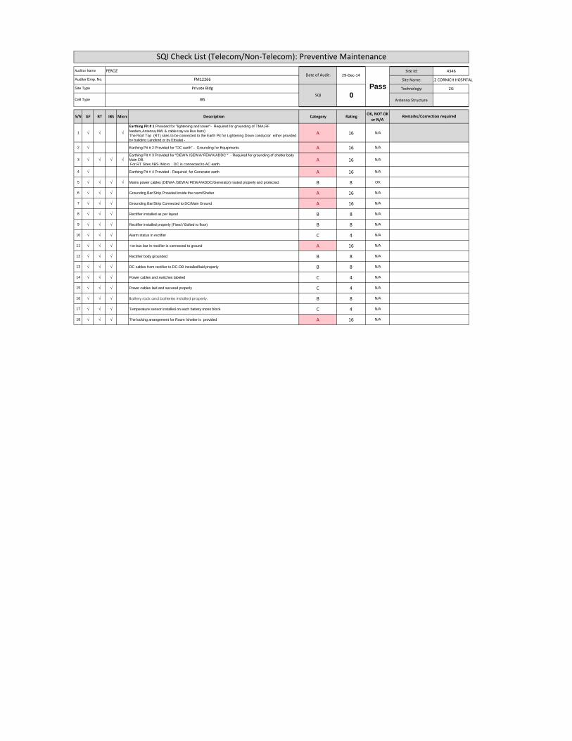
Site Id: 4346
Site Name: E12 CORNICH HOSPITAL
Technology: 2G
Antenna Structure
S/N GF RT IBS Micro Description Category RatingOK, NOT OK
or N/A
1 √ √ √
Earthing Pit # 1 Provided for "lightening and tower"- Required for grounding of TMA,RF
feeders,Antenna,MW & cable tray via Bus bars)
The Roof Top (RT) sites to be connected to the Earth Pit for Lightening Down conductor either provided
by building Landlord or by Etisalat -
A 16 N/A
2 √ Earthing Pit # 2 Provided for "DC earth" - Grounding for Equipments A 16 N/A
3 √ √ √ √Earthing Pit # 3 Provided for "DEWA /SEWA/ FEWA/ADDC " - Required for grounding of shelter body
Main DB.
For RT Sites /IBS /Micro , DC is connected to AC earth.A 16 N/A
4 √ Earthing Pit # 4 Provided - Required for Generator earth A 16 N/A
5 √ √ √ √ Mains power cables (DEWA /SEWA/ FEWA/ADDC/Generator) routed properly and protected. B 8 OK
6 √ √ √ Grounding Bar/Strip Provided inside the room/Shelter A 16 N/A
7 √ √ √ Grounding Bar/Strip Connected to DC/Main Ground A 16 N/A
8 √ √ √ Rectifier installed as per layout B 8 N/A
9 √ √ √ Rectifier installed properly (Fixed / Bolted to floor) B 8 N/A
10 √ √ √ Alarm status in rectifier C 4 N/A
11 √ √ √ +ve bus bar in rectifier is connected to ground A 16 N/A
12 √ √ √ Rectifier body grounded B 8 N/A
13 √ √ √ DC cables from rectifier to DC-DB installed/laid properly B 8 N/A
14 √ √ √ Power cables and switches labeled C 4 N/A
15 √ √ √ Power cables laid and secured properly C 4 N/A
16 √ √ √ Battery rack and batteries installed properly. B 8 N/A
17 √ √ √ Temperature sensor installed on each battery mono block C 4 N/A
18 √ √ √ The locking arrangement for Room /shelter is provided A 16 N/A
SQI Check List (Telecom/Non-Telecom): Preventive Maintenance
Remarks/Correction required
Site Type
Cell Type
Auditor Name
Auditor Emp. No.Date of Audit: 29-Dec-14
SQI 0
Pass
FEROZ
FM12266
Private Bldg
IBS
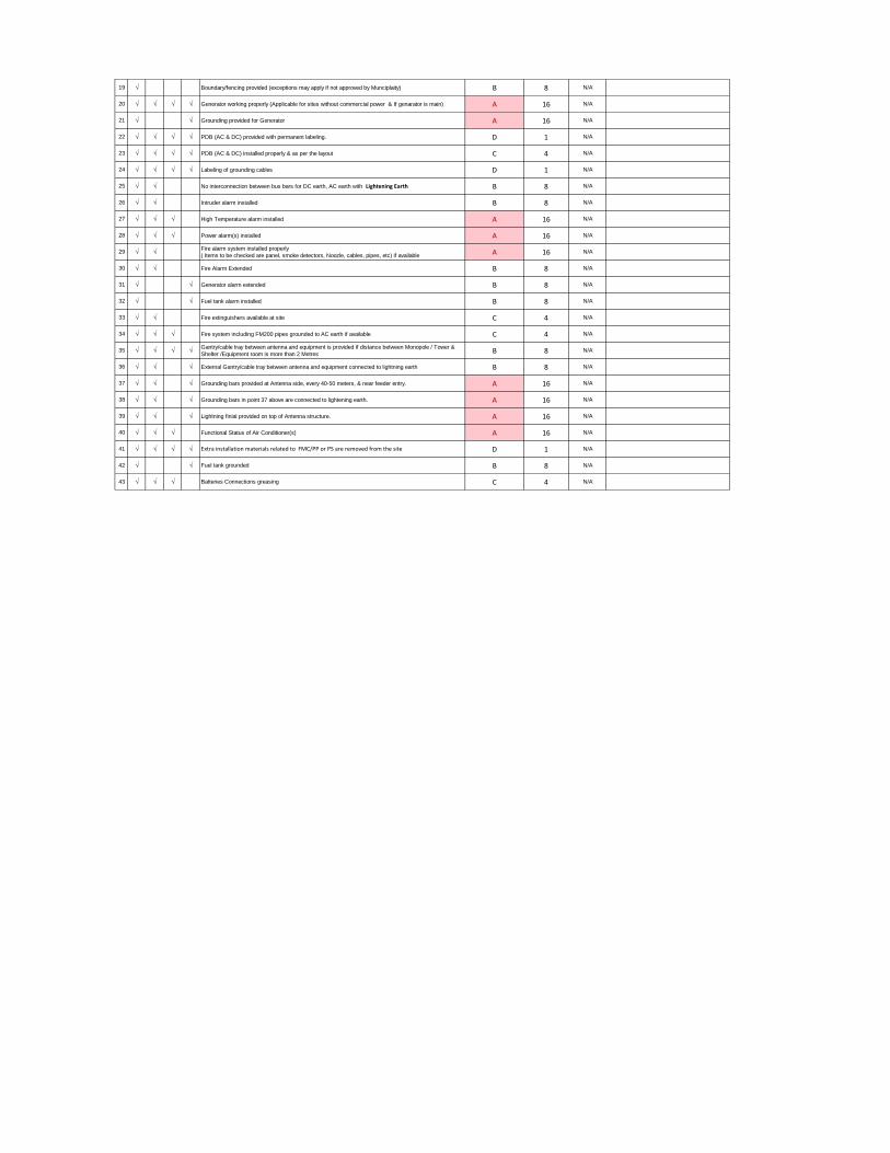
19 √ Boundary/fencing provided (exceptions may apply if not approved by Munciplaity) B 8 N/A
20 √ √ √ √ Generator working properly (Applicable for sites without commercial power & If genarator is main) A 16 N/A
21 √ √ Grounding provided for Generator A 16 N/A
22 √ √ √ √ PDB (AC & DC) provided with permanent labeling. D 1 N/A
23 √ √ √ √ PDB (AC & DC) installed properly & as per the layout C 4 N/A
24 √ √ √ √ Labeling of grounding cables D 1 N/A
25 √ √ No interconnection between bus bars for DC earth, AC earth with Lightening Earth B 8 N/A
26 √ √ Intruder alarm installed B 8 N/A
27 √ √ √ High Temperature alarm installed A 16 N/A
28 √ √ √ Power alarm(s) installed A 16 N/A
29 √ √Fire alarm system installed properly
( Items to be checked are panel, smoke detectors, Noozle, cables, pipes, etc) if availableA 16 N/A
30 √ √ Fire Alarm Extended B 8 N/A
31 √ √ Generator alarm extended B 8 N/A
32 √ √ Fuel tank alarm installed B 8 N/A
33 √ √ Fire extinguishers available at site C 4 N/A
34 √ √ √ Fire system including FM200 pipes grounded to AC earth if available C 4 N/A
35 √ √ √ √Gantry/cable tray between antenna and equipment is provided if distance between Monopole / Tower &
Shelter /Equipment room is more than 2 MetresB 8 N/A
36 √ √ √ External Gantry/cable tray between antenna and equipment connected to lightning earth B 8 N/A
37 √ √ √ Grounding bars provided at Antenna side, every 40-50 meters, & near feeder entry. A 16 N/A
38 √ √ √ Grounding bars in point 37 above are connected to lightening earth. A 16 N/A
39 √ √ √ Lightning finial provided on top of Antenna structure. A 16 N/A
40 √ √ √ Functional Status of Air Conditioner(s) A 16 N/A
41 √ √ √ √ Extra installation materials related to FMC/PP or PS are removed from the site D 1 N/A
42 √ √ Fuel tank grounded B 8 N/A
43 √ √ √ Batteries Connections greasing C 4 N/A
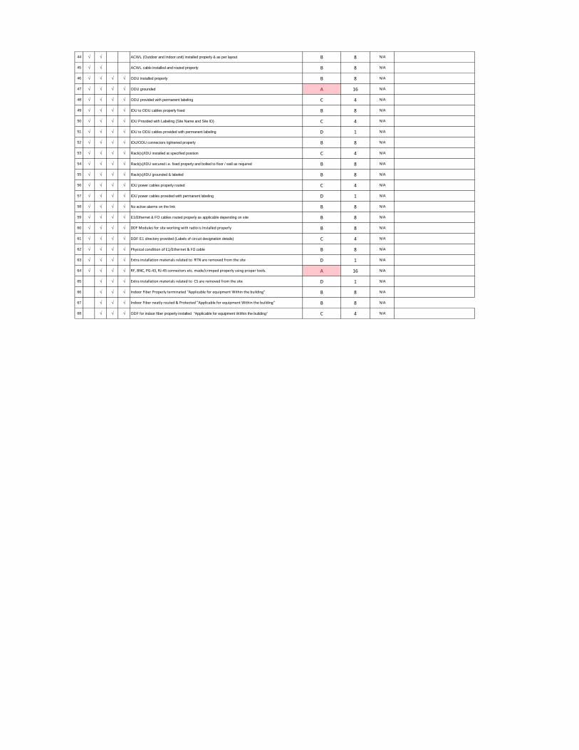
44 √ √ ACWL (Outdoor and Indoor unit) installed properly & as per layout B 8 N/A
45 √ √ ACWL cable installed and routed properly B 8 N/A
46 √ √ √ √ ODU installed properly B 8 N/A
47 √ √ √ √ ODU grounded A 16 N/A
48 √ √ √ √ ODU provided with permanent labeling C 4 N/A
49 √ √ √ √ IDU to ODU cables properly fixed B 8 N/A
50 √ √ √ √ IDU Provided with Labeling (Site Name and Site ID) C 4 N/A
51 √ √ √ √ IDU to ODU cables provided with permanent labeling D 1 N/A
52 √ √ √ √ IDU/ODU connectors tightened properly B 8 N/A
53 √ √ √ √ Rack(s)/IDU installed at specified position C 4 N/A
54 √ √ √ √ Rack(s)/IDU secured i.e. fixed properly and bolted to floor / wall as required B 8 N/A
55 √ √ √ √ Rack(s)/IDU grounded & labeled B 8 N/A
56 √ √ √ √ IDU power cables properly routed C 4 N/A
57 √ √ √ √ IDU power cables provided with permanent labeling D 1 N/A
58 √ √ √ √ No active alarms on the link B 8 N/A
59 √ √ √ √ E1/Ethernet & FO cables routed properly as applicable depending on site B 8 N/A
60 √ √ √ √ DDF Modules for site working with radio is Installed properly B 8 N/A
61 √ √ √ √ DDF E1 directory provided (Labels of circuit designation details) C 4 N/A
62 √ √ √ √ Physical condition of E1/Ethernet & FO cable B 8 N/A
63 √ √ √ √ Extra installation materials related to RTN are removed from the site D 1 N/A
64 √ √ √ √ RF, BNC, PG-43, RJ-45 connectors etc. made/crimped properly using proper tools. A 16 N/A
65 √ √ √ Extra installation materials related to CS are removed from the site D 1 N/A
66 √ √ √ Indoor Fiber Properly terminated "Applicable for equipment Within the building" B 8 N/A
67 √ √ √ Indoor Fiber neatly routed & Protected "Applicable for equipment Within the building" B 8 N/A
68 √ √ √ ODF for indoor fiber properly installed "Applicable for equipment Within the building" C 4 N/A
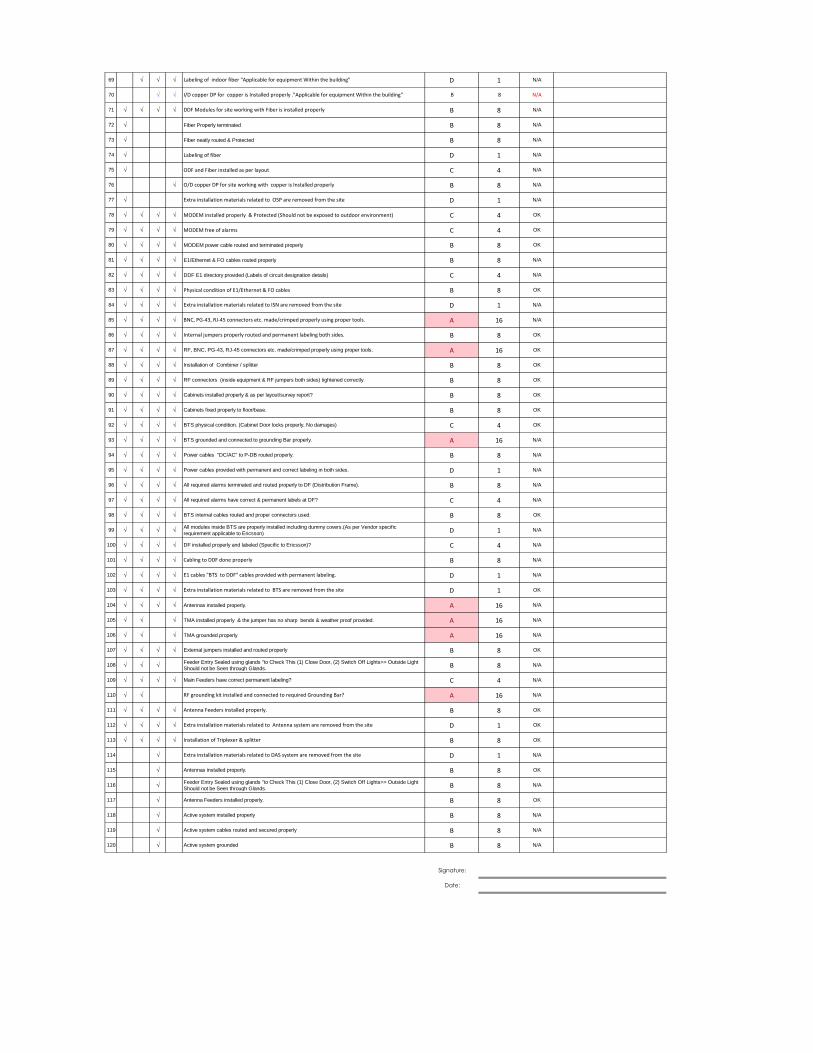
69 √ √ √ Labeling of indoor fiber "Applicable for equipment Within the building" D 1 N/A
70 √ √ I/D copper DP for copper is Installed properly ."Applicable for equipment Within the building" B 8 N/A
71 √ √ √ √ DDF Modules for site working with Fiber is installed properly B 8 N/A
72 √ Fiber Properly terminated B 8 N/A
73 √ Fiber neatly routed & Protected B 8 N/A
74 √ Labeling of fiber D 1 N/A
75 √ ODF and Fiber installed as per layout C 4 N/A
76 √ O/D copper DP for site working with copper is Installed properly B 8 N/A
77 √ Extra installation materials related to OSP are removed from the site D 1 N/A
78 √ √ √ √ MODEM installed properly & Protected (Should not be exposed to outdoor environment) C 4 OK
79 √ √ √ √ MODEM free of alarms C 4 OK
80 √ √ √ √ MODEM power cable routed and terminated properly B 8 OK
81 √ √ √ √ E1/Ethernet & FO cables routed properly B 8 N/A
82 √ √ √ √ DDF E1 directory provided (Labels of circuit designation details) C 4 N/A
83 √ √ √ √ Physical condition of E1/Ethernet & FO cables B 8 OK
84 √ √ √ √ Extra installation materials related to ISN are removed from the site D 1 N/A
85 √ √ √ √ BNC, PG-43, RJ-45 connectors etc. made/crimped properly using proper tools. A 16 N/A
86 √ √ √ √ Internal jumpers properly routed and permanent labeling both sides. B 8 OK
87 √ √ √ √ RF, BNC, PG-43, RJ-45 connectors etc. made/crimped properly using proper tools. A 16 OK
88 √ √ √ √ Installation of Combiner / splitter B 8 OK
89 √ √ √ √ RF connectors (inside equipment & RF jumpers both sides) tightened correctly. B 8 OK
90 √ √ √ √ Cabinets installed properly & as per layout/survey report? B 8 OK
91 √ √ √ √ Cabinets fixed properly to floor/base. B 8 OK
92 √ √ √ √ BTS physical condition. (Cabinet Door locks properly, No damages) C 4 OK
93 √ √ √ √ BTS grounded and connected to grounding Bar properly. A 16 N/A
94 √ √ √ √ Power cables "DC/AC" to P-DB routed properly. B 8 N/A
95 √ √ √ √ Power cables provided with permanent and correct labeling in both sides. D 1 N/A
96 √ √ √ √ All required alarms terminated and routed properly to DF (Distribution Frame). B 8 N/A
97 √ √ √ √ All required alarms have correct & permanent labels at DF? C 4 N/A
98 √ √ √ √ BTS internal cables routed and proper connectors used. B 8 OK
99 √ √ √ √All modules inside BTS are properly installed including dummy covers.(As per Vendor specific
requirement applicable to Ericsson)D 1 N/A
100 √ √ √ √ DF installed properly and labeled (Specific to Ericsson)? C 4 N/A
101 √ √ √ √ Cabling to DDF done properly B 8 N/A
102 √ √ √ √ E1 cables "BTS to DDF" cables provided with permanent labeling. D 1 N/A
103 √ √ √ √ Extra installation materials related to BTS are removed from the site D 1 OK
104 √ √ √ √ Antennas installed properly. A 16 N/A
105 √ √ √ TMA installed properly & the jumper has no sharp bends & weather proof provided. A 16 N/A
106 √ √ √ TMA grounded properly A 16 N/A
107 √ √ √ √ External jumpers installed and routed properly B 8 OK
108 √ √ √Feeder Entry Sealed using glands "to Check This (1) Close Door, (2) Switch Off Lights>> Outside Light
Should not be Seen through Glands.B 8 N/A
109 √ √ √ √ Main Feeders have correct permanent labeling? C 4 N/A
110 √ √ RF grounding kit installed and connected to required Grounding Bar? A 16 N/A
111 √ √ √ √ Antenna Feeders installed properly. B 8 OK
112 √ √ √ √ Extra installation materials related to Antenna system are removed from the site D 1 OK
113 √ √ √ √ Installation of Triplexer & splitter B 8 OK
114 √ Extra installation materials related to DAS system are removed from the site D 1 N/A
115 √ Antennas installed properly. B 8 OK
116 √Feeder Entry Sealed using glands "to Check This (1) Close Door, (2) Switch Off Lights>> Outside Light
Should not be Seen through Glands.B 8 N/A
117 √ Antenna Feeders installed properly. B 8 OK
118 √ Active system installed properly B 8 N/A
119 √ Active system cables routed and secured properly B 8 N/A
120 √ Active system grounded B 8 N/A
Signature:
Date:
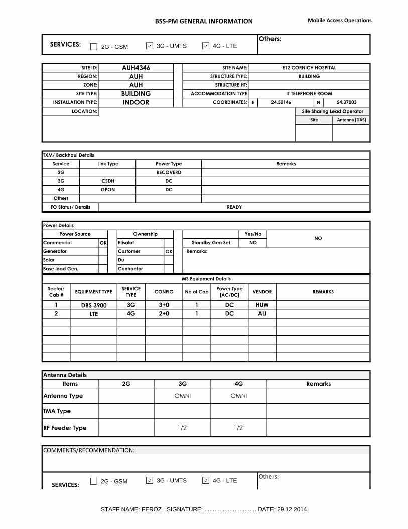
BSS-PM GENERAL INFORMATION Mobile Access Operations
E N
OK
OK
SERVICES:Others:
ZONE: AUH STRUCTURE HT:
SITE TYPE: BUILDING ACCOMMODATION TYPE IT TELEPHONE ROOM
SITE ID: AUH4346 SITE NAME: E12 CORNICH HOSPITAL
REGION: AUH STRUCTURE TYPE: BUILDING
Site Antenna [DAS]
INSTALLATION TYPE: INDOOR COORDINATES: 24.50146 54.37003
LOCATION: Site Sharing Lead Operator
TXM/ Backhaul Details
Service Link Type Power Type Remarks
2G RECOVERD
Others
FO Status/ Details READY
3G CSDH DC
4G GPON DC
Power Details
Power Source Ownership Yes/NoNO
Commercial Etisalat Standby Gen Set NO
Generator Customer Remarks:
Solar Du
Base load Gen. Contractor
MS Equipment Details
Sector/
Cab #EQUIPMENT TYPE
SERVICE
TYPECONFIG No of Cab
Power Type
[AC/DC] VENDOR REMARKS
HUW
2 LTE 4G 2+0 1 DC ALI
1 DBS 3900 3G 3+0 1 DC
Antenna Details
Items 2G 3G 4G Remarks
RF Feeder Type 1/2" 1/2"
Antenna Type OMNI OMNI
TMA Type
COMMENTS/RECOMMENDATION:
SERVICES:
Others:
2G - GSM 3G - UMTS 4G - LTE
2G - GSM 3G - UMTS 4G - LTE
STAFF NAME: FEROZ SIGNATURE: ................................DATE: 29.12.2014
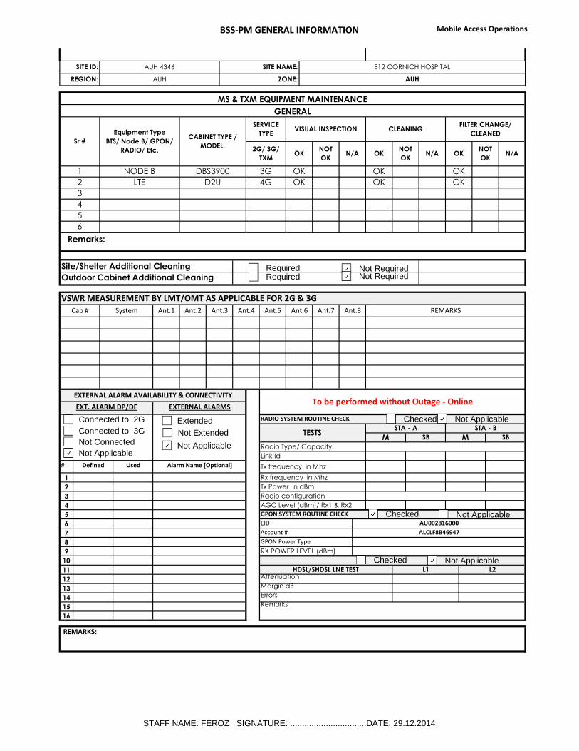
BSS-PM GENERAL INFORMATION Mobile Access Operations
#
1
2
3
4
5
6
7
8
9
10
11
12
13
14
15
16
SITE ID: AUH 4346 SITE NAME: E12 CORNICH HOSPITAL
REGION: AUH ZONE: AUH
SERVICES:
Others:
MS & TXM EQUIPMENT MAINTENANCE
GENERAL
Sr #
Equipment Type
BTS/ Node B/ GPON/
RADIO/ Etc.
CABINET TYPE /
MODEL:
SERVICE
TYPEVISUAL INSPECTION CLEANING
FILTER CHANGE/
CLEANED
2G/ 3G/
TXM
1 NODE B DBS3900 3G OK
OKNOT
OKN/A
OK OK
OKNOT
OKN/AOK
NOT
OKN/A
3
OK OK2 LTE D2U 4G OK
4
6
5
Remarks:
Site/Shelter Additional Cleaning
Outdoor Cabinet Additional Cleaning
VSWR MEASUREMENT BY LMT/OMT AS APPLICABLE FOR 2G & 3G
Cab # System Ant.1 Ant.2 Ant.3 Ant.4 Ant.5 Ant.6 Ant.7 Ant.8 REMARKS
EXTERNAL ALARM AVAILABILITY & CONNECTIVITYTo be performed without Outage - Online
EXT. ALARM DP/DF EXTERNAL ALARMS
Radio Type/ Capacity
Link Id
RADIO SYSTEM ROUTINE CHECK
TESTSSTA - A STA - B
M SB M SB
Rx frequency in Mhz
Defined Used Alarm Name [Optional] Tx frequency in Mhz
Radio configuration
Tx Power in dBm
GPON SYSTEM ROUTINE CHECK
AGC Level (dBm)/ Rx1 & Rx2
EID AU002816000
Account # ALCLF8B46947
GPON Power Type
RX POWER LEVEL (dBm)
AttenuationHDSL/SHDSL LNE TEST L1 L2
Errors
Margin dB
REMARKS:
Remarks
Extended
Not Extended
Not Applicable
Connected to 2G
Connected to 3G
Not Connected
Not Applicable
Checked Not Applicable
Checked Not Applicable
Checked Not Applicable
Required Not Required Required Not Required
STAFF NAME: FEROZ SIGNATURE: ................................DATE: 29.12.2014
BSS-PM GENERAL INFORMATION Mobile Access Operations
.
STAFF NAME: FEROZ SIGNATURE: ................................DATE: 29.12.2014
Recommended