ADVANCED TRACKING AND DATA RELAY EXPERIMENTS
STUDY - Multimode Transponder Experiment Equipment
Magnavox Research Laboratories2829 Maricopa StreetTorrance, California 90503
15 September 1973
Final Report for Period Sept. 1972 - Sept. 1973
Prepared for0
GODDARD SPACE FLIGHT CENTER
Greenbelt, Maryland 20771
(NASA-CR-132930) ADVANCED TRACKING AND N74-1688TDATA RELAY EXPERIMENTS STUDY: MULTIMODETRANSPONDER EXPERIMENT EQUIPMENT FinalReport, Sep. 1972 - Sep. 1973 (Magnavox UnclasResearch Labs.) -29 p HC $4.50 G3/07 30069
1. Report No. 2. Government Accession No. 3. Recipient's Catal No.
4. Title and Subtitle 5. Report Date
ADVANCED TRACKING AND DATA RELAY 15 September 1973
EXPERIMENTS STUDY - Multimode Transponder 6. Performing Organization Code
Experiment Equipment
7. Author(s) 8. Performing Organization Report No.
R. S. Cnossen R-4741
9. Performing Organization Name and Address 10. Work Unit No.
'The Magnavox Company 5Magnavox Research Laboratories 11. Contract or Grant No.
2829 Maricopa StreetTorrance, CA 90503 13. Type of Report and Period Covered
12. Sponsoring Agency Name and Address Type III
National Aeronautics and Space Administration Final Report9-72 to 9-73Goddard Space Flight Center 14. Sponsoring Agency Code
Greenbelt, Maryland 20771
15. Supplementary Notes
16. Abstract
Plans and implementation concepts have been developed for a series
of experiments utilizing a Multimode Transponder mounted in an aircraft
working either through a spacecraft or directly with a ground station which
would simulate a TDRSS user working through the TDRSS. The purpose of
the experiments would be to determine the best modulation and encoding
techniques for combating RFI in discreet bands. The experiments would also
determine the feasibility and accuracy of range and range rate measurements
with the various modulation and encoding techniques.
This report provides an analysis of the Multimode Transponder
and ground support equipment contracted for and determine the additional
equipment required to perform the experiments described above.
17. Key Words (Selected by Author(s)) 18. Distribution Statement
Experiment, Satellite Transponder,Modulation Evaluation
19. Security Classif. (of this report) 20. Security Classif. (of this pagei 21. No. of Pages 22. Price
Unclassified Unclassified 27
"For sale by the Clearinghouse for Federal Scientific and Technical Information, Springfield, Virginia 22151.
-7-
MRL TECHN ICAL INFORMATI ON NOTICE
All entries must be completed prior to printing. If a particular block isnot applicable, place NIA (not applicable) in the appropriate block.
DISTRIBUTION DATE 21 Sept. 1 3
AUTHOR CONTRIBUTORS MRL REFERENCE NO.R-4741
R. S. Cnossen J. Mackey DOCUMENT DATEDOCUMENT DATE15 September 1973
TITLE ADVANCED TRACKING AND DATA RELAY EXPERIMENTSSTUDY - Multimode Transponder Experiment Equipment
SUBJECT/I KEY WORDSExperiments, Satellite Transponder, Modulation Evaluation
GOVERNMENT CLASS TYPE OF INFORMATION NO. OF PAGESAND MRL CONTROL HO.
Unclassified Interim Report 27
MAGNAVOX CLASS NO. OF ILLUST.
Customer Only 16
ABSTRACT/I CONCLUSIONSPlans and implementation concepts have been developed for a
series of experiments utilizing a Multimode Transponder mounted inan aircraft working either through a spacecraft or directly with aground station which would simulate a TDRSS user Working throughthe TDRSS. The purpose of the experiments would be to determinethe best modulation and encoding techniques for combating RFI indiscreet bands. The experiments would also determine the feasibilityand accuracy of range and range rate measurements with the variousmodulation and encoding techniques.
This report provides an analysis of the Multimode Transponderand ground support equipment contracted for and determine theadditional equipment required to perform the experiments describedabove.
BY CUTTING OUT THIS RECTANGLE AND FOLDING ON THE CENTER LINE,THE ABOVE INFORMATION CAN BE FITTED INTO A STANDARD CARD FILE.
INFORMATION PREPARED FOR: National Aeronautics and Space Administration
APPROVED BY: PROGRAM MANAGER /. i -- - DATE: 21 Sept. 1973R. Cnossen
DEPARTMENT MANAGER DATE: 21 Sept. 1973B. Glazer-
7U-1002 A (See Reverse Side For Instructions)
PREFACE
This report, dated 15 September 1973, is entitled "Multimode TransponderExperiment Equipment. " It is the .econd of three reports which contain the findingsof a program titled "Advanced Tracking and Data Relay Experiments Study. " Thework was accomplished by the Magnavox Research Laboratories of Torrance,California and complies with the requirements of Contract Number NAS5-21824,Contract Data Item 4.
Plans and implementation concepts have been developed for a series ofexperiments utilizing a Multimode Transponder mounted in an aircraft working eitherthrough a spacecraft or directly with a ground station which would simulate a TDRSSuser working through the TDRSS. The purpose of the experiments would be todetermine the best modulation and encoding techniques for combating RFI and multi-
path propagation and to determine the characteristics of VHF and UHF RFI in discreetbands. The experiments would also determine the feasibility and accuracy of rangeand range rate measurements with the various modulation and encoding techniques.
This report provides an analysis of the Multimode Transponder and itsassociated ground support equipment contracted for and determines the additionalequipment required to perform the experiments described above.
Magnavox wishes to acknowledge the assistance of Pat Mitchell, ATDREtechnical officer and Keith Fellerman of the TDRSS program office, G. S. F. C.
This report was prepared by Messrs. R. Cnossen and J. Mackey of MRL.
ii
TABLE OF CONTENTS
Section Title Page
III ATDRE EQUIPMENT ............................. 3-1
3.1 MTAR/MMT Equipment ...................... 3-1
3.1.1 Functional Description ................. 3-1
3.2 MTAR Antenna ........................... 3-11
3.3 MTAR/MMT Interfaces ...................... 3-13
3.3.1 Mechanical Interface ................. 3-13
3.3.2 Lab Test Interface ................. 3-13
3.3.3 Flight Test Interface ................. 3-13
3.3.4 MTAR/MMT Monitor Signals ............. 3-13
3.3.5 External Interface Signal Specifications ..... 3-16
3.3.6 Range and Range Rate Signal Specifications. ... 3-18
3.4 TDRSS Van Equipment ...................... 3-19
3.5 Candidate Aircraft Equipment .................. 3-19
3.5.1 NASA Aircraft ................... . 3-20
3.5.2 Rockwell International Aircraft .......... 3-25
3.5.3 Flight Systems Test Aircraft .......... 3-25
3.6 Test Equipment ........................... 3-26
3.6.1 MX 270 Bit Error Rate Analyzer ....... 3-27
iii
LIST OF ILLUSTRATIONS
Figure Title Page
3-1 MTAR Receiver-Transmitter ..................... 3-2
3-2 MTAR Signal Processor ......................... 3-2
3-3 MTAR and MMT Control/Display Panels ............... 3-3
3-4 MTAR Receiver, Block Diagram .................... 3-5
3-5 MTAR Transmitter, Block Diagram ................... 3-6
3-6 MMT Receiver, Block Diagram ....................... 3-8
3-7 MMT Transmitter, Block Diagram ................... 3-10
3-8 Trapezoidal Log-Periodic Antenna Array .............. . 3-11
3-9 Feed Schematic for Orthogonal Log-Periodic Arrays ....... 3-12
3-10 Rack Configuration for Both MMT and MTAR Equipments ..... 3-14
3-11 MMT/MTAR Lab Test Box Interface ................... 3-15
3-12 MTAR Flight Test Data Interface .................. ... 3-15
3-13 MMT Flight Test Data Interface ..................... 3-16
3-14 C121G Aircraft Interior Arrangements ................. 3-22
3-15 Convair 340 Aircraft Interior Arrangements ............ 3-24
3-16 MX 270 Bit Error Rate Analyzer .................... 3-27
iv
SECTION III
ATDRE EQUI PMENT
The Multimode Transponder and the Multimode Transmitter and Receiver
Units are described in this section along with the support equipment required to
perform the experiments detailed in Section II.
Part 1 provides a functional description of both the MMT and MTAR
equipments. It includes diagrams of the signal interfaces and includes a description
of the MTAR antenna developed for this program. Part 2 details the required test
equipment needed to support the test series. Part 3 provides a brief description of
the NASA mobile test station which would be used for the flight test series. Finally,
part 4 gives a summary of the airborne test beds which were considered during the
study.
3.1 MTAR/MMT EQUIPMENT
3.1.1 FUNCTIONAL DESCRIPTION
The section contains a description of the MTAR (ground) and the MMT
(airborne) equipment developed for evaluating candidate modulation techniques for
TDRSS.
The MTAR equipment consists of four chassis:
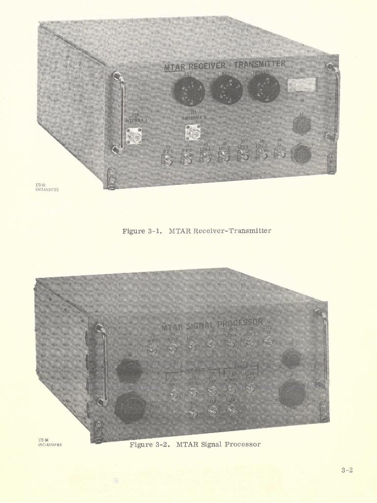
1. The Receiver-Transmitter contains the RF to IF sections for both
the receiver and the transmitter. It is shown in figure 3-1.
2. The Signal Processor contains all circuits from IF to baseboard for
both the transmitter and receiver. It is shown in figure 3-2.
3. The Power Supply provides all supply potentials to the other three
chassis and its appearance is similar to the Signal Processor.
4. The Control/Display Panel houses all mode selection switches
and indicates the operational status of the equipment. It is shown in figure 3-3.
The MMT equipment also consists of four chassis which are similar in
function and almost identical in appearance to the MTAR equipment. The Control/
Display Panel for the MMT is shown in figure 3-3.
3-1
~~tK
MT Pc~
IF2 kFLDS~ Fgre32.MA SgllPocso
173-85
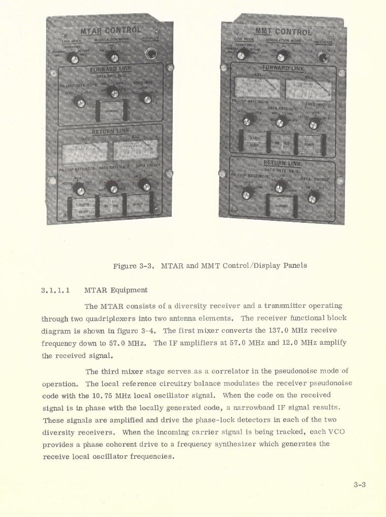
Figure 3-3. MTAR and MMT Control/Display Panels
3.1.1.1 MTAR Equipment
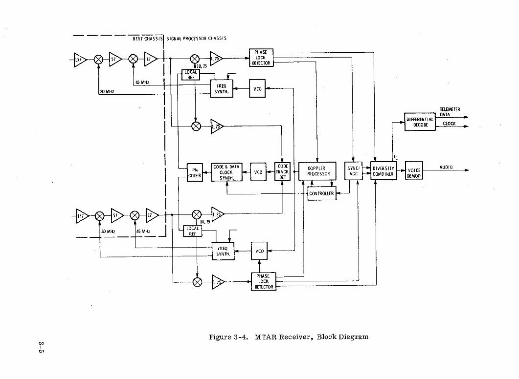
The MTAR consists of a diversity receiver and a transmitter operating
through two quadriplexers into two antenna elements. The receiver functional block
diagram is shown in figure 3-4. The first mixer converts the 137.0 MHz receive
frequency down to 57.0 MHz. The IF amplifiers at 57.0 MHz and 12.0 MHz amplify
the received signal.
The third mixer stage serves as a correlator in the pseudonoise mode of
operation. The local reference circuitry balance modulates the receiver pseudonoise
code with the 10. 75 MHz local oscillator signal. When the code on the received
signal is in phase with the locally generated code, a narrowband IF signal results.
These signals are amplified and drive the phase-lock detectors in each of the two
diversity receivers. When the incoming carrier signal is being tracked, each VCO
provides a phase coherent drive to a frequency synthesizer which generates the
receive local oscillator frequencies.
3-3
In the pseudonoise mode the code tracking loop keeps the receiver refta -
ence code in phase with the code on the received signal. In each receiver the incom-
ing signal goes to a separate correlator and 1. 25 MHz IF amplifier. The local
reference provides this correlator with an early-late code from which a tracking
error signal is derived. These error signals are combined and filtered in the code
track detector and drive a single-clock VCO. Diversity reception requires two
receivers because the propagation time difference due to the spatial relationship of
the antennas is in the order of a full cycle at the RF carrier frequency. The code-
track error signals can be combined to drive a single VCO because the 10 ns time
difference in the received signals is insignificant at the code-chip rates used. The
code and data-clock synthesizer is driven by the clock VCO and generates the selected
chip-rate clock for the receive coder. In the conventional PSK mode the clock VCO
and synthesizer are used to recover the received digital data clock.
The in-phase (I) outputs of the phase-lock detectors are combined in
the diversity combiner. The telemetry digital data or PDM voice is extracted from
the I-combined signal.
The doppler processor in conjunction with the controller searches out the
doppler frequency uncertainty to obtain carrier lock. The anticipated doppler fre-
quency error for the TDRS system is much greater than the carrier loop filter band-
width. The doppler processor employs a technique that searches out the doppler
uncertainty much faster than a linear cell-by-cell frequency search. Both the carrier
frequency and code-phase uncertainties must be resolved. The controller advanced
or retards the code clock phase to obtain pseudonoise code synchronization. The
sync-AGC circuitry makes the sync-search decision and generates the AGC signals
to control IF amplifier gain.
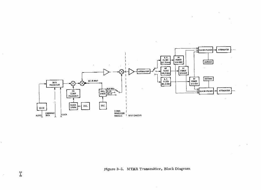
The MTAR transmitter functions are shown in figure 3-5. The output arihpli-
fier drives into a variable attenuator for output power control. The attenuator is
connected to the appropirate bandpass filter for the frequency to be transmitted. An
RF power divider for each of the bandpass filters provides the outputs to the dual
quadriplexer and attenuator arrangement.
A frequency synthesizer driven by a stable crystal-controlled oscillator
provides three transmit local-oscillator frequencies and the transmit carrier. One
of the three local-oscillator frequencies is selected for mixing with the modulated
67.76 MHz transmit carrier to obtain the desired output frequency.
3-4
RFIIF CHASSIS I SIGNAL PROCESSOR CHASSIS
PHASEF I•137 57 12 2LOCK
IECTOR10.75
LO ALREF
45 MHzVCO
80 MHz ;SYNTH.
TELEMETERDATA
DE VRENTIALDECODE I CLOCK
I
, ATAIC AUDIO
CD DOPPLER SYNC DIVERSITYP NL O C A T V C 0 T R A C K -
COD RH PROCESSOR AGC COMBINERSY TH. DEo
CONTROLLER
137Ng 51 12 eee
I1
0 .7 5
80 MHz 45 MHz _1 LOCAL
REFQ
FREQ VC0SYNTH.
Ir PHASE
1.2 'LOCK
Figure 3-4. MTAR Receiver, Block DiagramWr
QUADRIPLEXER ATTENUATOR
B. P. RFFILTER POWER
COERDIVIDER ANTENNA
sp RF
ATTENUA FR ILTER POWER9 'MH, 0 VIDER
NMB. RF ANTENNA
DATA "6.I H\FILTER POWER
PROCESSOR 401.0 DIVIDER
0 MHzFREQ. 81.25 QUDRIPLXER ATENUAOR
CODER SYNTH 333 25(TRANSMIT)
CLOCK OSC OSC.VOI~tCOMMN~i LOCK SYNTH.
VOICE tSIGNAL
COMMANDPROCESSORAUDIO DATA CHASSIS I RFIIF CHASSIS
Figure 3-5. MTAR Transmitter, Block Diagram
In the PSK mode digital data or PDM voice is balance modulated on the
carrier. In the PN mode the digital data or PDM voice is combined with the pseudo-
noise code before being balance modulated with the carrier. The selected code-chi.-
rate clock is generated by a synthesizer driven by a stable oscillator at 10. 24 MHz.
3.1.1.2 MMT Equipment
The MMT functions as a coherent transponder with the transmit carrier
frequency synthesized from the receiver VCO tracking the forward link signal. The
MTAR transmits to and detects the signal received from the MMT. Control box
selection of modulation mode, command and telemetry data rates and pseudonoise
chip rates, is provided. Digital data error rates can be measured both with and
without convolutional encoding. A voice channel can be selected for both forward
and return links. The return link carrier frequency will be 137. 0 MHz while one of
three frequencies (127. 75 MHz, 149. 0 MHz or 401. 0 MHz) can be selected for the
forward link.
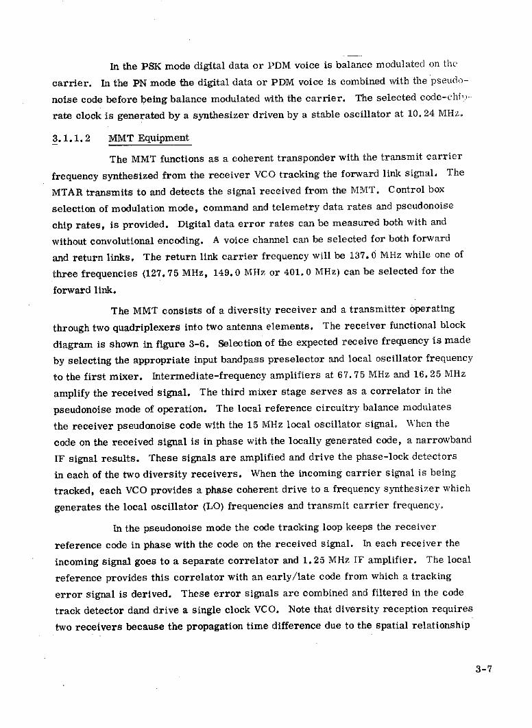
The MMT consists of a diversity receiver and a transmitter operating
through two quadriplexers into two antenna elements. The receiver functional block
diagram is shown in figure 3-6. Selection of the expected receive frequency is made
by selecting the appropriate input bandpass preselector and local oscillator frequency
to the first mixer. Intermediate-frequency amplifiers at 67. 75 MHz and 16. 25 MHz
amplify the received signal. The third mixer stage serves as a correlator in the
pseudonoise mode of operation. The local reference circuitry balance modulates
the receiver pseudonoise code with the 15 MHz local oscillator signal. When the
code on the received signal is in phase with the locally generated code, a narrowband
IF signal results. These signals are amplified and drive the phase-lock detectors
in each of the two diversity receivers. When the incoming carrier signal is being
tracked, each VCO provides a phase coherent drive to a frequency synthesizer which
generates the local oscillator (LO) frequencies and transmit carrier frequency.
In the pseudonoise mode the code tracking loop keeps the receiver
reference code in phase with the code on the received signal. In each receiver the
incoming signal goes to a separate correlator and 1. 25 MHz IF amplifier. The local
reference provides this correlator with an early/late code from which a tracking
error signal is derived. These error signals are combined and filtered in the code
track detector dand drive a single clock VCO. Note that diversity reception requires
two receivers because the propagation time difference due to the spatial relationship
3-7
401
PHASE DIFFERENTIAL COMMANDQUADIPLEXER 149 67.750 16.250 1.250 LOCK DECODE DTA
LOCAL 15 MHz
127.750 MHz 8MHz
A SYNTH
ANT. 0 TX1137 MHz
333.25081.25O.560.0 MHz
ANT. 1.250 B ICI-7
PN CODE & DATA CODE PROCESSOR AUI CMBNER DEMOD.CODER CCLOCK VCO TRACK
RE CIVE TO YNTH. I ETCONTROLLER
QUADRIPLEXER 149 7.750 16.20 1.250
15 MHz
84 MHz LOCAL
127.750 MHz FREQ. 137 MHz
0 SYNTH
PHASE1.250 LOCK
DETECTOR
Figure 3-6. MMT Receiver, Block Diagram
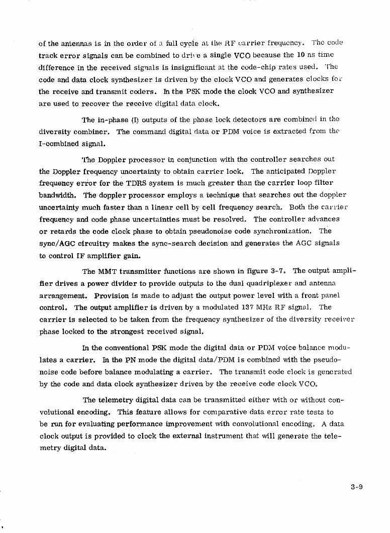
of the antennas is in the order of a full cycle at the RF carrier frequency. The code
track error signals can be combined to drive a single VCO because the 10 ns time
difference in the received signals is insignificant at the code-chip rates used. The
code and data clock synthesizer is driven by the clock VCO and generates clocks for
the receive and transmit coders. In the PSK mode the clock VCO and synthesizer
are used to recover the receive digital data clock.
The in-phase (I) outputs of the phase lock detectors are combined in the
diversity combiner. The command digital data or PDM voice is extracted from the
I-combined signal.
The Doppler processor in conjunction with the controller searches out
the Doppler frequency uncertainty to obtain carrier lock. The anticipated Doppler
frequency error for the TDRS system is much greater than the carrier loop filter
bandwidth. The doppler processor employs a technique that searches out the doppler
uncertainty much faster than a linear cell by cell frequency search. Both the carrier
frequency and code phase uncertainties must be resolved. The controller advances
or retards the code clock phase to obtain pseudonoise code synchronization. The
sync/AGC circuitry makes the sync-search decision and generates the AGC signals
to control IF amplifier gain.
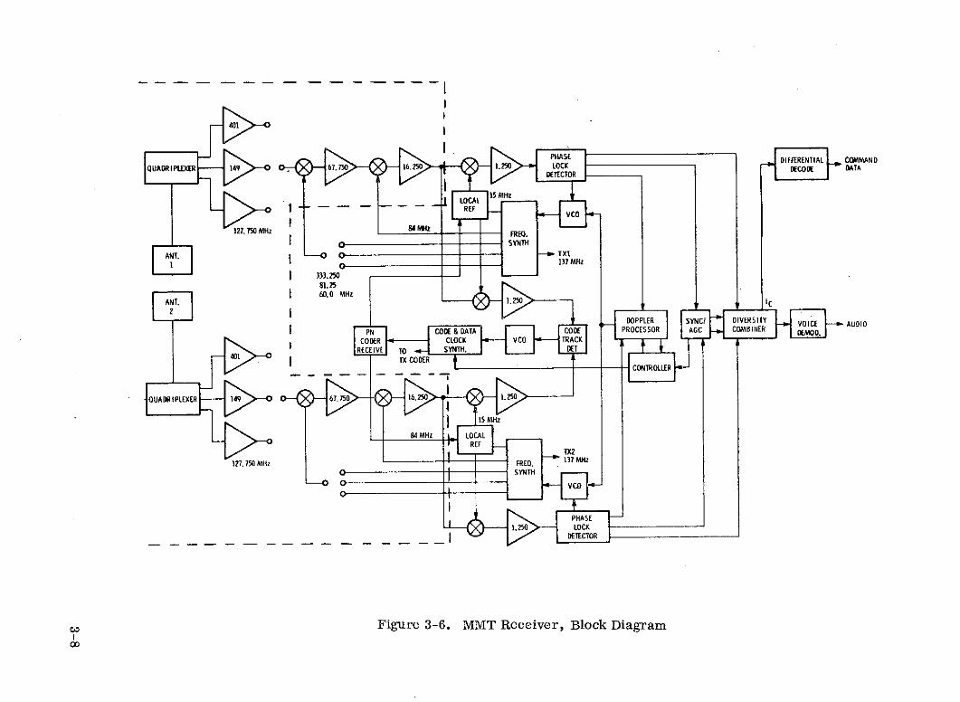
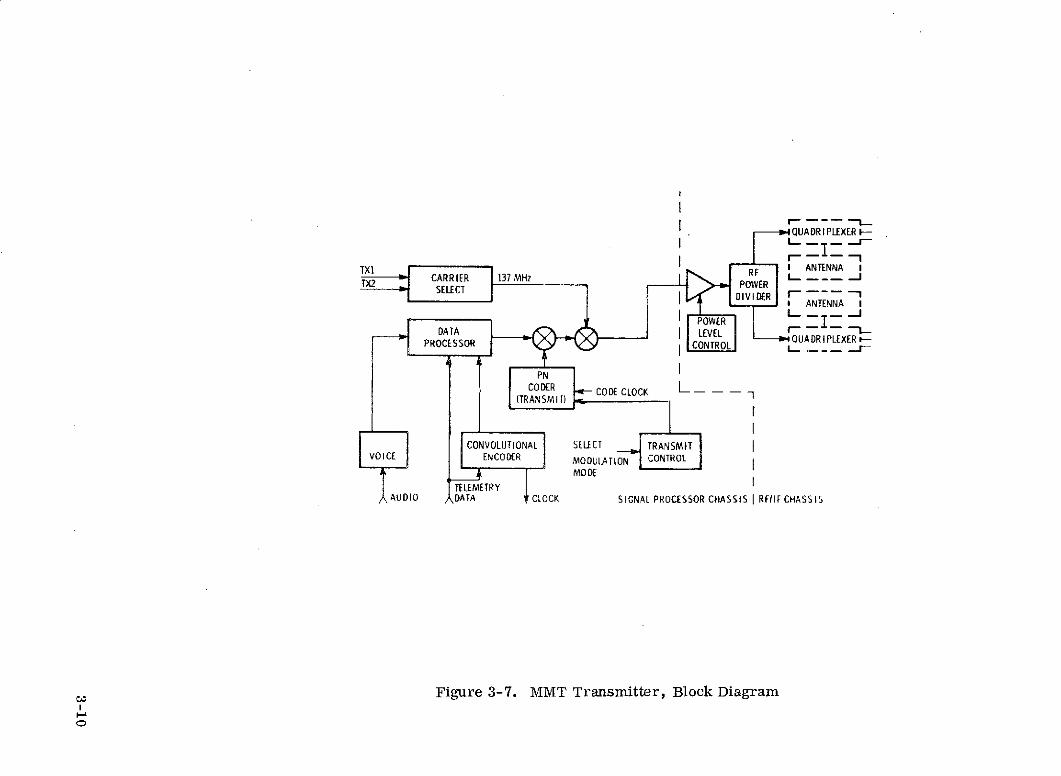
The MMT transmitter functions are shown in figure 3-7. The output ampli-
fier drives a power divider to provide outputs to the dual quadriplexer and antenna
arrangement. Provision is made to adjust the output power level with a front panel
control. The output amplifier is driven by a modulated 137 MHz RF signal. The
carrier is selected to be taken from the frequency synthesizer of the diversity receiver
phase locked to the strongest received signal.
In the conventional PSK mode the digital data or PDM voice balance modu-
lates a carrier. In the PN mode the digital data/PDM is combined with the pseudo-
noise code before balance modulating a carrier. The transmit code clock is generated
by the code and data clock synthesizer driven by the receive code clock VCO.
The telemetry digital data can be transmitted either with or without con-
volutional encoding. This feature allows for comparative data error rate tests to
be run for evaluating performance improvement with convolutional encoding. A data
clock output is provided to clock the external instrument that will generate the tele-
metry digital data.
3-9
QUADR IPLEXER I--
II CARRIER 137 MHz L. -
TX2 -POWERSELECT DIVIDER ---- 1
* ANTENNA
POWERDATA LEVEL -PROCESSOR QUADR I PLEXERPROCESSOR CONTROL
PNCODER CODE CLOCK L
(TRANSMI T)
CONVOLUTIONAL SELECT TRANSMITVOICE ENCODER MODULATION CONTROL
MODETELEMETRY
AUDIO DATA CLOCK SIGNAL PROCESSOR CHASSIS I RFIIF CHASSIS
Figure 3-7. MMT Transmitter, Block Diagram
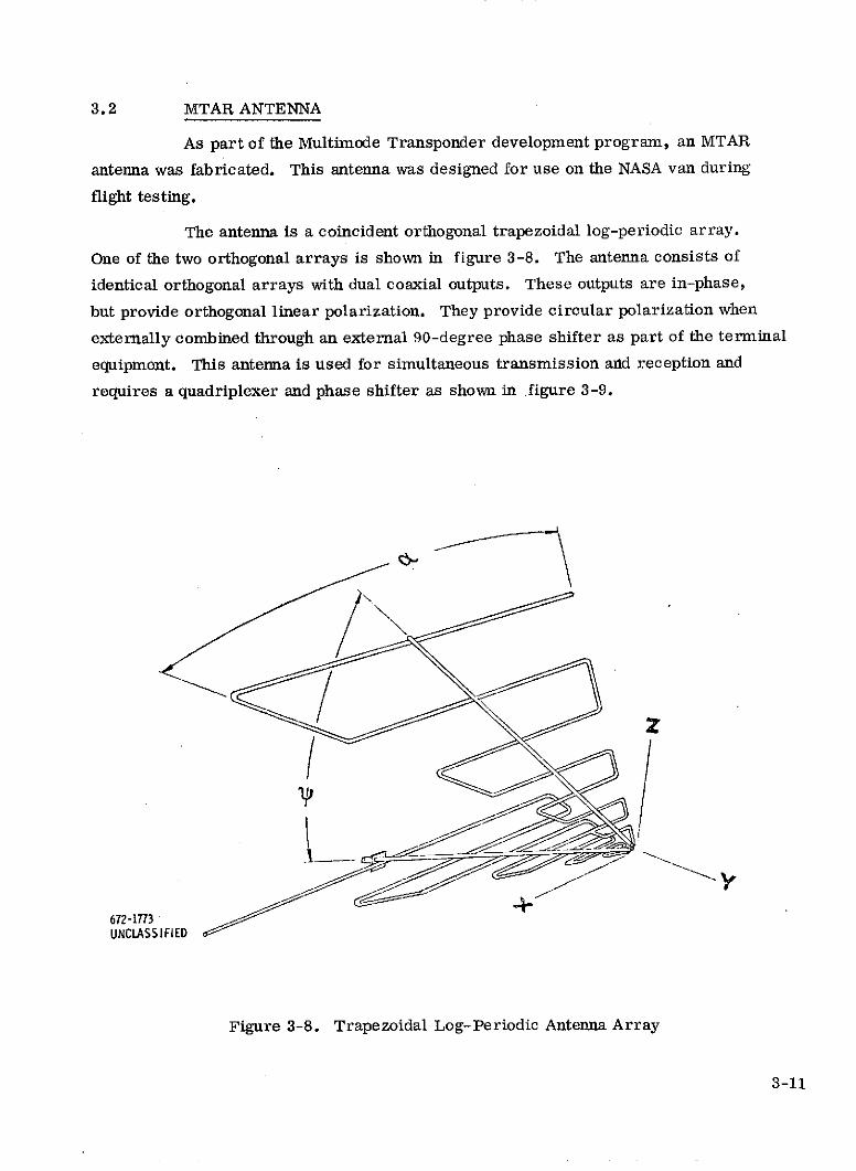
3.2 MTAR ANTENNA
As part of the Multimode Transponder development program, an MTAR
antenna was fabricated. This antenna was designed for use on the NASA van during
flight testing.
The antenna is a coincident orthogonal trapezoidal log-periodic array.
One of the two orthogonal arrays is shown in figure 3-8. The antenna consists of
identical orthogonal arrays with dual coaxial outputs. These outputs are in-phase,
but provide orthogonal linear polarization. They provide circular polarization when
externally combined through an external 90-degree phase shifter as part of the terminal
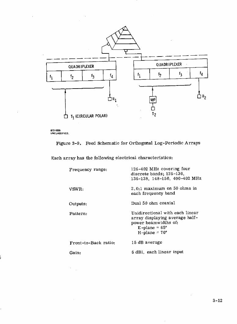
equipment. This antenna is used for simultaneous transmission and reception and
requires a quadriplexer and phase shifter as shown in figure 3-9.
7
672-1773UNCLASSIFIED
Figure 3-8. Trapezoidal Log-Periodic Antenna Array
3-11
QUADRIPLEXER QUADRIPLEXER
S2 1 2 3 f3
R1 R2
T1 (CIRCULAR POLAR) T2
672-1595UNCLASSIFIED.
Figure 3-9. Feed Schematic for Orthogonal Log-Periodic Arrays
Each array has the following electrical characteristics:
Frequency range: 126-402 MHz covering fourdiscrete bands; 126-130,136-138, 148-150, 400-402 MHz
VSWR: 2.0:1 maximum on 50 ohms ineach frequency band
Outputs: Dual 50 ohm coaxial
Pattern: Unidirectional with each lineararray displaying average half-power beamwidths of:
E -plane = 650H-plane = 700
Front-to-Back ratio: 15 dB average
Gain: 6 dBi, each linear input
3-12
3.3 MTAR/MMT INTERFACES
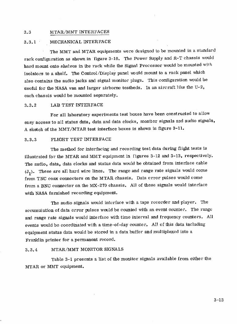
3.3.1 MECHANICAL INTERFACE
The MMT and MTAR equipments were designed to be mounted in a standard
rack configuration as shown in figure 3-10. The Power Supply and R-T chassis would
hard mount onto shelves in the rack while the Signal Processor would be mounted with
isolators to a shelf. The Control/Display panel would mount to a rack panel which
also contains the audio jacks and signal monitor plugs. This configuration would be
useful for the NASA van and larger airborne testbeds. In an aircraft like the U-2,
each chassis would be mounted separately.
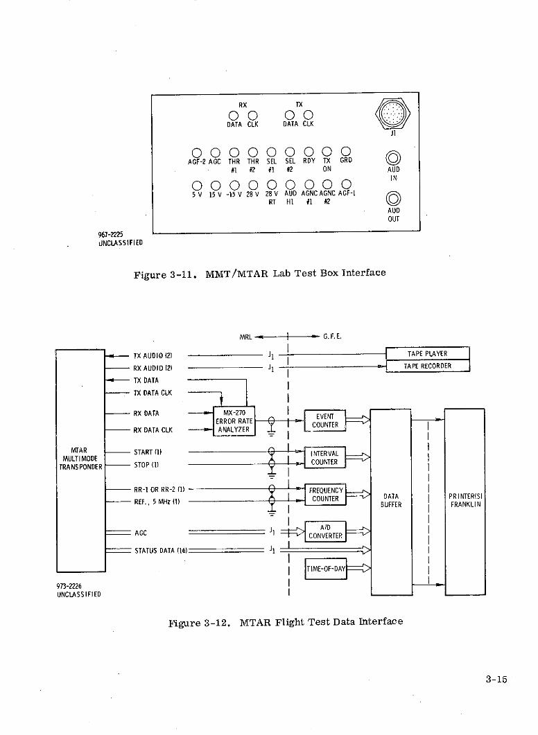
3.3.2 LAB TEST INTERFACE
For all laboratory experiments test boxes have been constructed to allow
easy access to all status data, data and data clocks, monitor signals and audio signals,
A sketch of the MMT/MTAR test interface boxes is shown in figure 3-11.
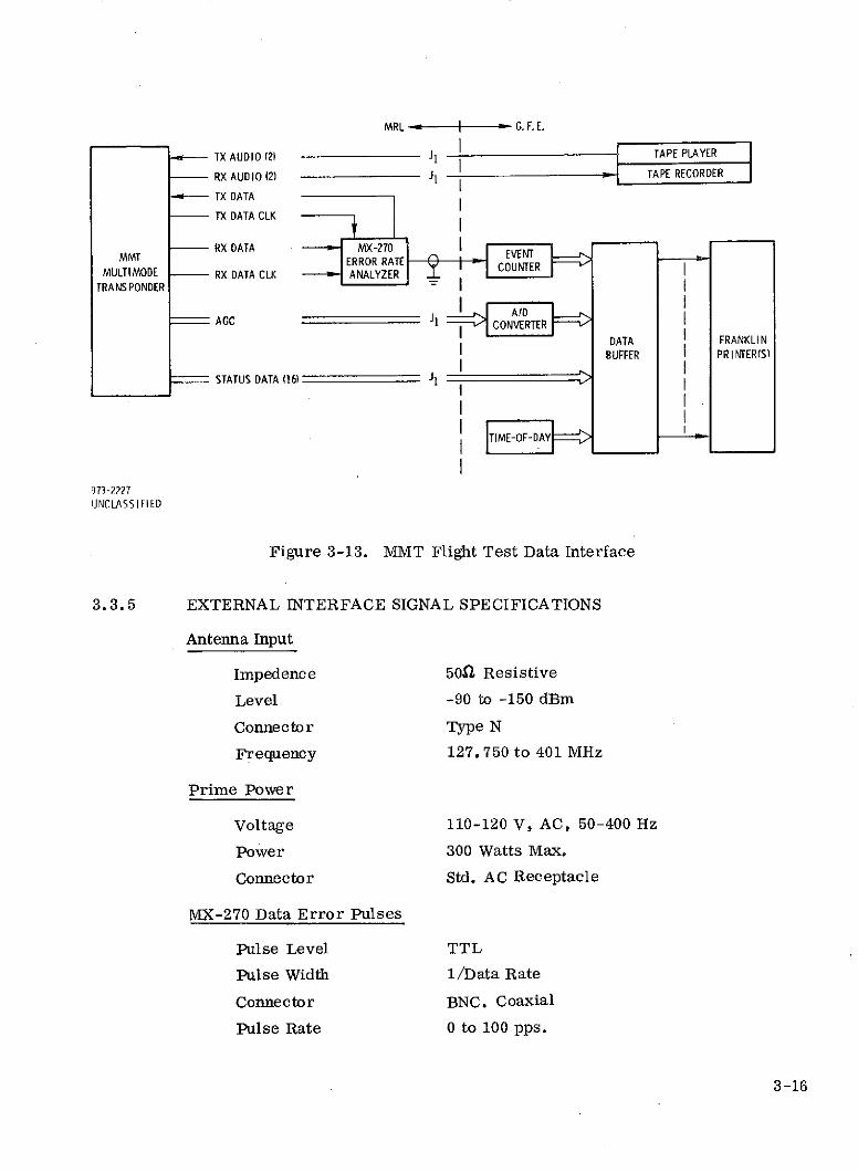
3.3.3 FLIGHT TEST INTERFACE
The method for interfacing and recording test data during flight tests is
illustrated for the MTAR and MMT equipment in figures 3-12 and 3-13, respectively.
The audio, data, data clocks and status data would be obtained from interface cable
(J1). These are all hard wire lines. The range and range rate signals would come
from TNC coax connectors on the MTAR chassis. Data error pulses would come
from a BNC connector on the MX-270 chassis. All of these signals would interface
with NASA furnished recording equipment.
The audio signals would interface with a tape recorder and player. The
accumulation of data error pulses would be counted with an event counter. The range
and range rate signals would interface with time interval and frequency counters. All
events would be coordinated with a time-of-day counter. All of this data including
equipment status data would be stored in a data buffer and multiplexed into a
Franklin printer for a.permanent record.
3.3.4 MTAR/MMT MONITOR SIGNALS
Table 3-1 presents a list of the monitor signals available from either the
MTAR or MMT equipment.
3-13
173-82UNCLASSIFIED
Figure 3-10. Rack Configuration For Both MMT and MTAR Equipments
3-14
RX TX
00 00DATA CLK DATA CLK
J1
000000000AGF-2 AGC THR THR SEL SEL RDY TX GRD
#1 #2 #1 #2 ON AUD
000000000 IN
5 V 15 V -15 V 28V 28V AUD AGNC AGNC AGF-1RT HI #1 #2
AUDOUT
967-2225UNCLASSIFIED
Figure 3-11. MMT/MTAR Lab Test Box Interface
MRL G.F.E.
TX AUDIO (2) J1 TAPE PLAYER
RX AUDIO (2) 1 TAPE RECORDER
TX DATA
TX DATA CLK
RX DATA X MX-270 EVENTERROR RATE N ER
RX DATA CLK ANALYZER L
MTAR - START (1) INTERVALMULTI MODE I NTER
TRANSPONDER - STOP (1) COUNER
RR-1 OR RR-2 (1) FREQUENCY- REF., 5MHz () COUNTER DATA I PRINTER(S)
REF.,BUFFER FRANKLIN
AGC J1 AID
CONVERTER
STATUS DATA (16) J1
TIME-OF-DAY
973-2226UNCLASSIFIED
Figure 3-12. MTAR Flight Test Data Interface
3-15
MRL I G. F. E.
TX AUDIO (2) J1 TAPE PLAYER
RX AUDIO (2) 1 - TAPE RECORDER
TX DATA
TX DATA CLK
RX DATA MX-270MMT ERROR RATE EVENT
MULTIMODE - RX DATA CLK ANALYZERTRANSPONDER
AGC JACC - -1 CONVERTER
DATA FRANKLINBUFFER PR I NTER(S)
STATUS DATA (16) J1
UNCLASSIFIED
Figure 3-13. MMT Flight Test Data Interface
3.3.5 EXTERNAL INTERFACE SIGNAL SPECIFICATIONS
Antenna Input
Impedence 50Q Resistive
Level -90 to -150 dBm
Connector Type N
Frequency 127. 750 to 401 MHz
Prime Power
Voltage 110-120 V, AC, 50-400 Hz
Power 300 Watts Max.
Connector Std. AC Receptacle
MX-270 Data Error Pulses
Pulse Level TTL
Pulse Width 1/Data Rate
Connector BNC. Coaxial
Pulse Rate 0 to 100 pps.
3-16
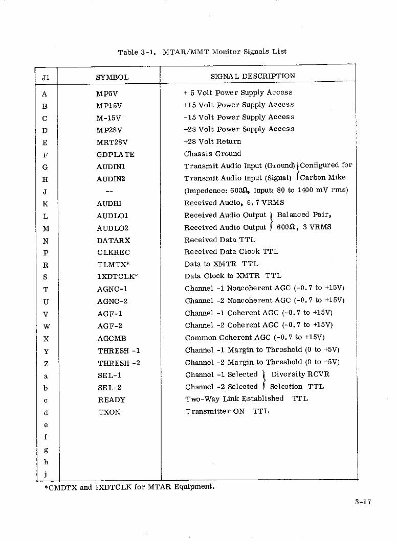
Table 3-1. MTAR/MMT Monitor Signals List
J1 SYMBOL SIGNAL DESCRIPTION
A MP5V + 5 Volt Power Supply Access
B MP15V +15 Volt Power Supply Access
C M-15V -15 Volt Power Supply Access
D MP28V +28 Volt Power Supply Access
E MRT28V +28 Volt Return
F GDPLA TE Chassis Ground
G AUDIN1 Transmit Audio Input (Ground) Configured for
H AUDIN2 Transmit Audio Input (Signal) Carbon Mike
J -- (Impedence: 600Q, Input: 80 to 1400 mV rms)
K AUDHI Received Audio, 6.7 VRMS
L AUDLO1 Received Audio Output Balanced Pair,
M AUDLO2 Received Audio Output 600Q, 3 VRMS
N DATARX Received Data TTL
P CLKREC Received Data Clock TTL
R TLMTX* Data to XMTR TTL
S 1XDTCLK* Data Clock to XMTR TTL
T AGNC-1 Channel -1 Noncoherent AGC (-0.7 to +15V)
U AGNC-2 Channel -2 Noncoherent AGC (-0.7 to +15V)
V AGF-1 Channel -1 Coherent AGC (-0.7 to +15V)
W AGF-2 Channel -2 Coherent AGC (-0.7 to +15V)
X AGCMB Common Coherent AGC (-0.7 to +15V)
Y THRESH -1 Channel -1 Margin to Threshold (0 to +5V)
Z THRESH -2 Channel -2 Margin to Threshold (0 to +5V)
a SEL-1 Channel -1 Selected Diversity RCVR
b SEL-2 Channel -2 Selected Selection TTL
c READY Two-Way Link Established TTL
d TXON Transmitter ON TTL
e
f
g
h
*CMDTX and 1XDTCLK for MTAR Equipment.
3-17
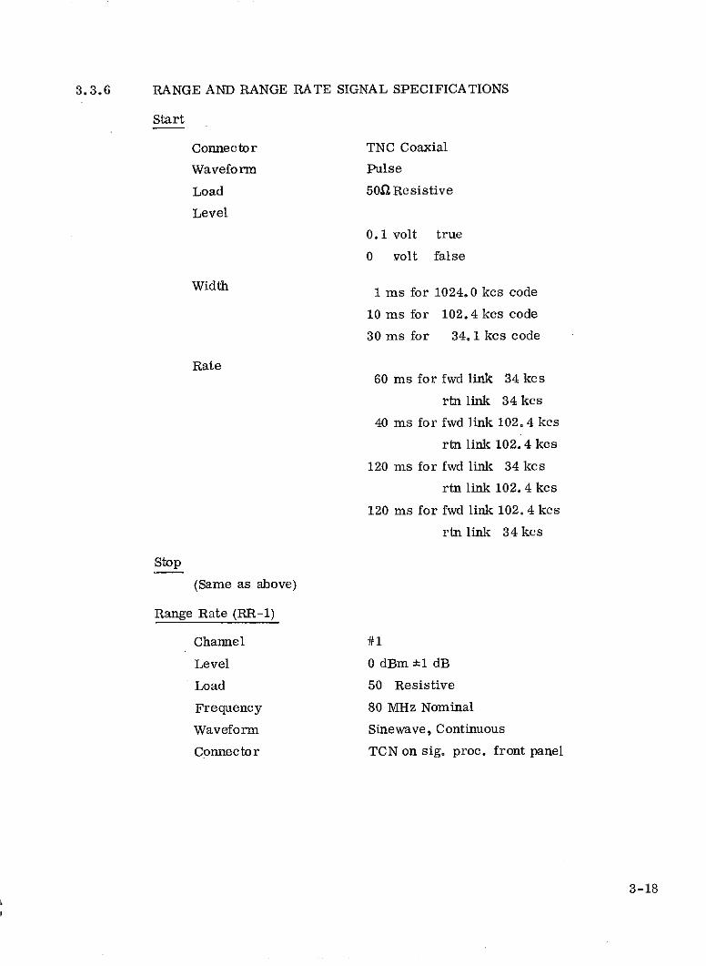
3.3.6 RANGE AND RANGE RATE SIGNAL SPECIFICATIONS
Start
Connector TNC Coaxial
Waveform Pulse
Load 50n Resistive
Level
0.1 volt true
0 volt false
Width 1 ms for 1024.0 kcs code10 ms for 1024.04 kcs code
30 ms for 34. 1 kcs code
Rate60 ms for fwd link 34 kcs
rtn link 34 kcs
40 ms for fwd link 102. 4 kcs
rtn link 102. 4 kcs
120 ms for fwd link 34 kcs
rtn link 102. 4 kcs
120 ms for fwd link 102. 4 kcs
rtn link 34 kcs
Stop
(Same as above)
Range Rate (RR-1)
Channel #1
Level 0 dBm ±1 dB
Load 50 Resistive
Frequency 80 MHz Nominal
Waveform Sinewave, Continuous
Connector TCN on sig. proc. front panel
3-18
Range Rate (RR-2)
Channel /#2
Level 0 dBm ±1 dB
Load 50S Resistive
Frequency 80 MHz Nominal
Waveform Sinewave, Continuous
Connector TNC on sig. proc. front panel
Reference
Frequency 5 MHz
Level 0 dBm ±1 dB
Load 50a Resistive
Waveform Sinewave
Connector TNC on sig. proc. front panel
3,4 TDRSS VAN EQUIPMENT
Goddard Space Flight Center has a modile test van which has been
identified as a TDRS Test Van. This mobile unit could house the MTAR equipment
during air-to-ground testing.
The van is RFI insulated, contains many racks of test equipment, has a
self contained power generator and has considerable flexibility for a wide range of
experiments. A list of available test equipment in the van has been evaluated and
found to be more than adequate for the proposed tests. The only known equipment
needed, in addition to the MTAR equipment, MTAR antenna and a MX-270 Bit Error
Rate Analyzer, is a data multiplexer and storage unit for interfacing the test data outputs
with a Franklin printer. This item would be supplied by NASA.
3.5 CANDIDATE AIRCRA FT EQUIPMENT
A number of aircraft suitable for flight testing were evaluated during this
study. They include aircraft which could be furnished by NASA, Flight Systems, Inc,
and Rockwell, Int. A capsule summary of these aircraft will be presented in this
sec tion.
3-19
3.5.1 NASA AIRCRAFT
Four NASA aircraft were identified and found useful for flight testing.
They are the (1) C121G Super Constellation, (2) DC-6, (3) Convair 340 and (4) U-2.
The first three could provide a suitable airborne testbed for air-to-ground experiments
and the fourth would be suitable for use as a high altitude aircraft during air-to-air
experiments.
3.5.1.1 C121G Super Constellation
The aircraft types are as follows:
N420NA C121G Super Constellation
N421NA C121G Super Constellation
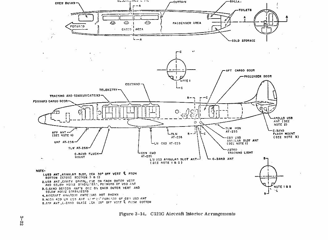
Aircraft operating characteristics are summarized in table 3-2. Aircraft
interior arrangements and antenna locations are shown in figure 3-14.
The instrumentation section of the aircraft consists of 16 racks containing
more than 30 pieces of commercial and special test equipment in addition to the
Apollo/LM Simulator System.
Electrical power is supplied to the equipment racks by four 115-vac 60-Hz
inverters and six 115-vac, 400-Hz inverters. Ten regulated dc power supplies provide
regulated 28-vdc, and each rack is connected to the aircraft 28 vdc bus, 300 amps,
max., for unregulated power.
The instrumented aircraft can provide a dynamic tracking target and a
data transmission source. The system is capable of receiving signals normally
transmitted from the MSFN station to the Apollo CSM/LM spacecraft. System
capabilities may be summarized as follows:
* Transmission of voice, telemetry, and television data to the station.
* Reception and demodulation of voice transmission from the station.
* Reception, demodulation, decoding, and verification of station generated
digital data.
0 Voice transmission in backup mode.
0 Voice reception in backup mode.
0 Transmission of emergency keyed signals to the station.
3-20
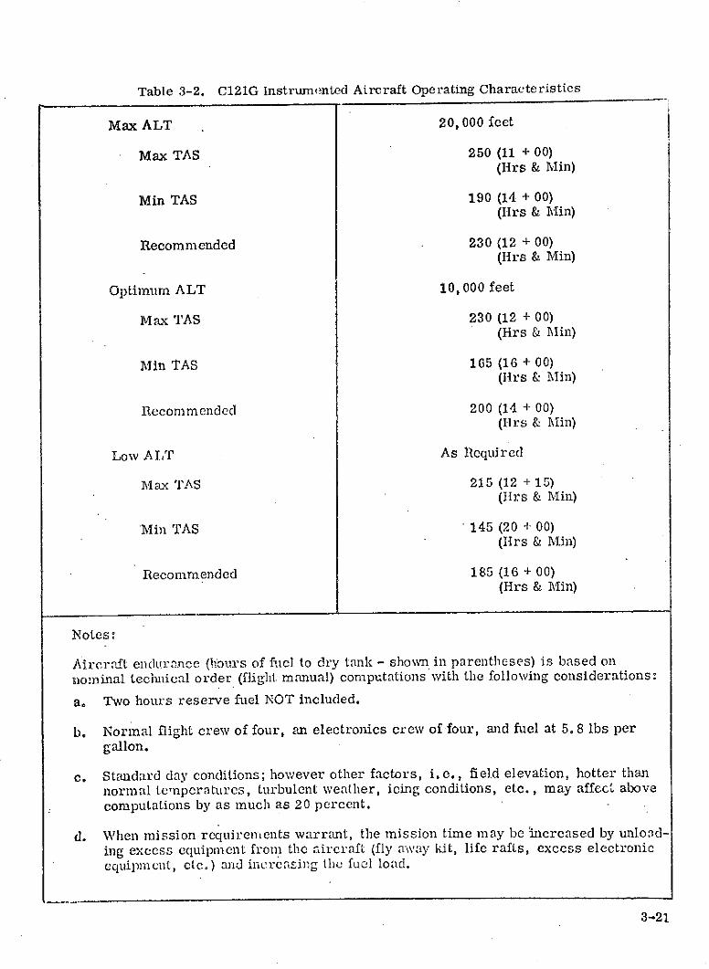
Table 3-2. C121G Instrumented Aircraft Operating Characteristics
Max ALT 20, 000 feet
Max TAS 250 (11 + 00)(lirs & Min)
Min TAS 190 (14 + 00)(Hrs & Min)
Recommended 230 (12 + 00)(Hrs & Min)
Optimum ALT 10, 000 feet
Max TAS 230 (12 + 00)(Hrs & Min)
Min TAS 165 (16 + 00)(Hrs & Min)
Recommended 200 (14 + 00)(Hrs & Min)
Low ALT As Required
Max TAS 215 (12 + 15)(Hlrs & Min)
Min TAS ' 145 (20 + 00)(IIrs & in)
Recommended 185 (16 + 00)(Hrs & Min)
Notes:
Aircraft endurance (hours of fuel to dry tank - shown in parentheses) is based onnominal technical order (flight manual) computations with the following considerations:
a. Two hours reserve fuel NOT included.
b. Normal flight crew of four, an electronics crew of four, and fuel at 5. 8 lbs pergallon.
c. Standard day conditions; however other factors, i.e., field elevation, hotter thannormal temperatures, turbulent weather, icing conditions, etc., may affect abovecomputations by as much as 20 percent.
d. When mission requirements warrant, the mission time may be increased by unlod-ing excess equipment from the aircraft (fly away kit, life rafts, excess electronicequipment, etc.) and increasing the fuel load.
3-21
CREV DUNKS,,i.tAIN LL-A
TOLET
FORC
A- AFT CARGO DOOR
PASSEMOER DOOR
8- -CFO ARD C ARGO DOOR-,,
L f I .__ I- _-_--- "--------- =- ---- - - -- APOLLO US$-NOTE 2)
r L HTLM MON
AFP ANT- .T,. - - AT-2 c-ADO
IOAT-.;6 .CS, UV0 (GEE NOTE 3)
UHF AVT- - / AN::'LAR SLOT ANTL.M CM O AT-.03 (SEE VOTE 1)
TLM AT-26 STO
C.-SAND FLUSH CS4 CWD TRACKINO LIGHT
tOUNIT AT-25GLTl "D0 ANNULA,7 SLOT ANT C-CAND ANT 8(ZrZ NOTE I0 03)
NOTE'
I.US3 ANT ,A%!NULAR SLOT, 2EA 30" OFF VERT ~. FROmTTOM (COS SECTION '0 C)
2.Ut ANT ,CAVITY PIrAL, .:E ON ACH OUTER VE.T
AND CLOW HXOIZ STADL!E%., FC::WOD OF US ANT
3.C-.AND EACONI NT'S O: ON EACH OUTER VERT AND NOTE I 5
EELOW HOMIZ Srt.SILIZZRSD
4.AIRCRAFT NAV/COM A.NTE'::IAC NOT SON5. NASA 420 LM LUS AnT i . "roRv.~o OF CS USO ANT
0.AFP ANT ,L-AD GLA.E LEA 25o OF V r-T 2L Fri., GOTTOM
Figure 3-14. C121G Aircraft Interior Arrangements
e Provision of a time reference for all time dependent subsystems.
* Reception and coherent retransmission of ranging signals transmitted
by the station.
3.5.1.2 DC-6 Aircraft
NASA has a DC-6 aircraft which would be ideal for flight testing. It's
flight performance is on the same order as the C121. Up to 5 racks are available for
mounting experimental equipment. It is heavily equipped with conventional test
equipment.
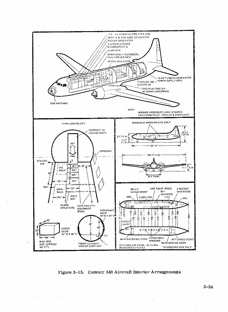
3,5.1.3 Convair 340 Aircraft
The Ames Convair 340 flying laboratory is a two-engine, low-wing
monoplane with a pressurized cabin. The aircraft is powered by two R-2800 recipro-
cating engines with thrust reversers. The thrust reversers are for ground use only.
The aircraft is equipped with an all-electric, Sperry A-12 Gyro-Pilot
System. A mechanical engaging lever provides connection of the aileron, rudder,
and elevator to the autopilot system. Control of the system is exercised from the
autopilot controller unit located on the pilot's pedestal.
The aircraft is equipped with one VHF and one UHF transceiver for radio
communic ation.
The aircraft is supplied power for its standard equipment from engine-
driven generators, and inverters. Power used for all experimental equipment is
supplied from a 14 KW gas turbine power plant located in the aft section of the
aircraft.
Access to the aircraft as shown in figure 3-15 is through the main
entrance door with integral stairs (door opening: 28" wide x 581" high). Space is
available along the left side of the cabin compartment for installation of additional
equipment. Seat tracks are installed for easy installation of properly designed
equipment racks. All experimental equipment to be placed on board the aircraft
must be approved by an Air Safety Board.
The aircraft has no unusual flight characteristics. Stall warning commences
approximately 15% above the indicated stall speed. The aircraft is stable under all
normal flight conditions. Maximum diving indicated airspeed from 10,000 feet to
sea level is 295 knots. Normal cruise in the terminal area is 140 to 160 knots
indicated airspeed. Aircraft landing velocity is about 100 knots indicated airspeed.
3-23
L.1N 1, HADAR ALTIMETER & UMS
DMS P S. & TIME CODE GENEHAlOR
DISPLAY GFNEHAEOR
2 GY ROPLATFORM
//& COMPUTER P. S.SCOMPUI E R
STRIP CHART RECORDERS,MiAG TAPE & PUNCHSTATIC INVERTI ERS
,,' i -14 KW TURBINE GENERATOR2 ROTARY 400 POWER SUPPLY (APU)
,- INVERTERSA RADAR ALTIMETER
ANTENNA UNDERWING
DMS ANTENNANOTE:
NORMAL PASSENGER LOAD .8 PEOPLEEXCLUDING PILOT - COPILOT & CREW CHIEF
VIEW LOOKING AFT WINDOW STARBOARD SIDE ONLY
DOORWAY TOLOUNGE ROOM 281.64 IN.FT
9FT5 'C u 1.6 IN.
AFAFT ,_ .2.1 1N81' 4"
WINDOWS
FWD -. - 105FT4IN.
STATION -"518 v
1B4 35"SINV. 11 F 5 N,SRACK 18"
82" L- -J 18% F"
35" 16
101W MAIN 23" BELLY EXP. EQUIP. SPACE 2 ROTARY
RACK CARGO DOOR* 60' INVERTERSIINVERTER
... ISLE DMS COMPUTER LAV APU-L24E" WAY .APU
FLOOR EXPERIMENTA'
STRUCTURE EQUIPMENT tSPACE PASSENGER lJ - w 1
25" " _ P c
EDOOR
78" oo 0 .CARGO 6" o a 055"n DOOR J35" W X 48" H
MAIN ENTRANCE DOOR REMOVABLE AFT CARGODOORMAX.BOX WINDOWS AT CARGO DOR'
SIZE (APPROX) FRONT CUTAWAY STTIONSAREFRREAR SERVICE DOOR
(47 FT3 )
VIEW FUSELAGE MASUREDININCHES ' STARBOARD SIDE ONLY
Figure 3-15. Convair 340 Aircraft Interior Arrangements
3-24
3.5.1.4 U-2 Aircraft
The U-2 is a NASA owned high altitude aircraft which would be suitable
for air-to-air flight experiments. The U-2 is currently making scheduled flights
between Ames and Wallop's Island. A piggyback arrangement for a number of
experiments and some dedicated flights may be possible. The scheduled missions
pass by the vicinity of Edward's Air Force Base where a ground station could be
located.
During high altitude flights (65 k feet) the cabin area is pressurized to
30 k feet and temperatures drop to 20 0 C. This environment appears reasonable for
the multimode transponder equipment. It has been verified that there is adequate
space and power available to accommodate the MMT equipment. A suitable antenna
would have to be installed by Lockheed, subcontractor for all U-2 modifications.
3.5.2 ROCKWELL INTERNATIONAL AIRCRAFT
Rockwell has a Sabreliner (N287NA) which could be used as an airborne
testbed. It has been used in the past to perform RFI surveys for NASA (Contract
No. NAS5-22009).
This aircraft is suitable for 2-3 hour flights at altitudes of 30,000 feet.
The aircraft has adequate space for the MTAR equipment, its associated test equip-
ment and a flight test operator.
The Sabreliner is configured with a 28 volt power and it has inverters
that produce 115 volts AC, 60 and 400 Hz. The available aircraft power supply is
more than adequate to furnish the requirements for the experiment equipment.
3.5.3 FLIGHT SYSTEMS TEST AIRCRAFT
Flight Systems Test, Inc. could provide a number of suitable aircraft
for the flight experiments. After reviewing the requirements for an air-to-ground
test series, F. S. T. has reccommended a T-33 aircraft.
All aircraft modification and installation would be provided by F. S. T. A
suitable antenna would be furnished for VHF/UHF operations. Operating costs are
estimated at $650/hour.
3-25
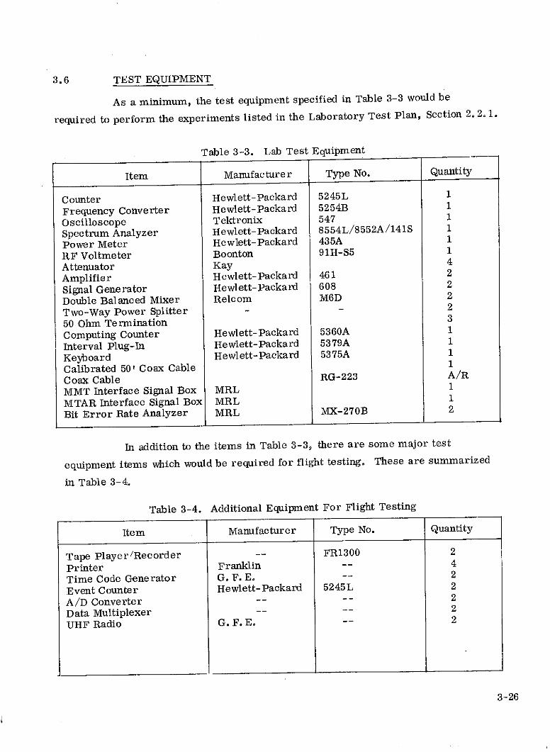
3.6 TEST EQUIPMENT
As a minimum, the test equipment specified in Table 3-3 would be
required to perform the experiments listed in the Laboratory Test Plan, Section 2. 2. 1.
Table 3-3. Lab Test Equipment
Item Manufacturer Type No. Quantity
Counter Hewlett-Packard 5245L 1
Frequency Converter Hewlett-Packard 5254B 1
Oscilloscope Tektronix 547 1
Spectrum Analyzer Hewlett-Packard 8554L/8552A/141S 1
Power Meter Hewlett-Packard 435A 1
RF Voltmeter Boonton 91H-S5 1
Attenuator Kay 4
Amplifier Hewlett-Packard 461 2
Signal Generator Hewlett-Packard 608 2
Double Balanced Mixer Relcom M6D 2
Two-Way Power Splitter 2
50 Ohm Termination 3
Computing Counter Hewlett-Packard 5360A 1
Interval Plug-In Hewlett-Packard 5379A 1
Keyboard Hewlett-Packard 5375A 1
Calibrated 50' Coax Cable 1
Coax Cable RG-223 A/R
MMT Interface Signal Box MRL 1
MTAR Interface Signal Box MRL 1
Bit Error Rate Analyzer MRL MX-270B 2
In addition to the items in Table 3-3, there are some major test
equipment items which would be required for flight testing. These are summarized
in Table 3-4.
Table 3-4. Additional Equipment For Flight Testing
Item Manufacturer Type No. Quantity
Tape Player/Recorder -- FR1300 2
Printer Franklin -- 4
Time Code Generator G. F. E. -- 2
Event Counter Hewlett-Packard 5245L 2
A/D Converter -- 2
Data Multiplexer -- -- 2
UHF Radio G. F. E. -- 2
3-26
3.6.1 MX-270 BIT ERROR RATE ANALYZER
As part of the overall multimode transponder design a data source was
provided at both the MMT and MTAR terminals to simulate telemetry and command
data sources respectively. A pair of Magnavox MX-270 Bit Error Rate Analyzers
were selected for the task. In addition to functioning as data generators, they will
provide a method for measuring bit-error rates.
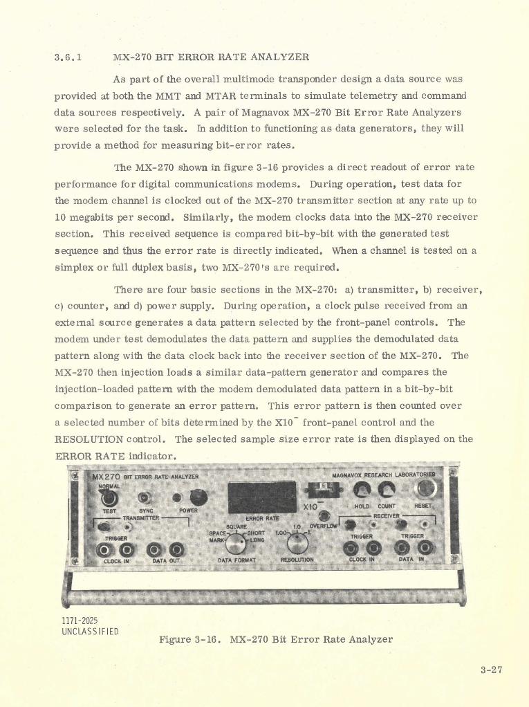
The MX-270 shown in figure 3-16 provides a direct readout of error rate
performance for digital communications modems. During operation, test data for
the modem channel is clocked out of the MX-270 transmitter section at any rate up to
10 megabits per second. Similarly, the modem clocks data into the MX-270 receiver
section. This received sequence is compared bit-by-bit with the generated test
sequence and thus the error rate is directly indicated. When a channel is tested on a
simplex or full duplex basis, two MX-270's are required.
There are four basic sections in the MX-270: a) transmitter, b) receiver,
c) counter, and d) power supply. During operation, a clock pulse received from an
external source generates a data pattern selected by the front-panel controls. The
modem under test demodulates the data pattern and supplies the demodulated data
pattern along with the data clock back into the receiver section of the MX-270. The
MX-270 then injection loads a similar data-pattern generator and compares the
injection-loaded pattern with the modem demodulated data pattern in a bit-by-bit
comparison to generate an error pattern. This error pattern is then counted over
a selected number of bits determined by the X10 front-panel control and the
RESOLUTION control. The selected sample size error rate is then displayed on the
ERROR RATE indicator.
X 270 SIT ERROR RATE ANALYZER MAGNAVOX RESEARCH LABORATORIES
X10 HOLD COUNT RESET
e GG GGEcLOCK IN DATA OUT DATA FORMAT RE&OTION CLOCK IN DATA IN
1171-2025UNCLASSIFIED
Figure 3-16. MX-270 Bit Error Rate Analyzer
3-27
Recommended