DISTRIBUTED BY
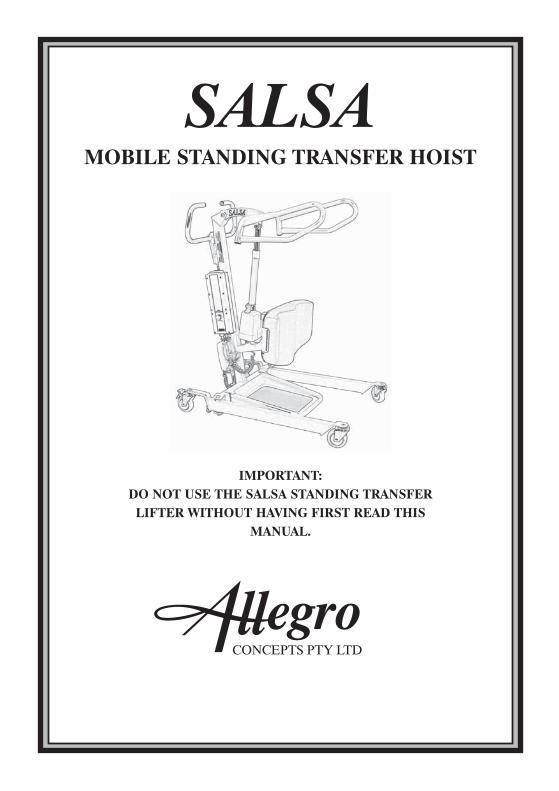
SALSA MOBILE STANDING TRANSFER HOIST
IMPORTANT DO NOT USE THE SALSA STANDING TRANSFER
LIFTER WITHOUT HAVING FIRST READ THIS
MANUAL
13
LOG BOOK
SERVICE TYPE
DATE
INSPECTED BY
NEKATNOITCAERUTANGIS
CONDITION REPORT
SERVICE TYPE
DATE
INSPECTED BY
NEKATNOITCAERUTANGIS
CONDITION REPORT
1
2
CONTENTS
SALSA LIFT 200 OVERVIEW
IMPORTANT SAFETY CONSIDERATIONS
SALSA LIFT 200 ASSEMBLY INSTRUCTIONS
HOIST OPERATION AND CHARGING
LIFTING PROCEDURES
MAINTENANCE
TROUBLE SHOOTING
SPECIFICATIONS
WARRANTY
LOG BOOK
3
5
8
9
10
11
12
13
WARRANTYALLEGRO CONCEPTS PTY LTD warrants its products to be free from defects inmaterials and workmanship under normal use and service and will within the periodstated below from the date of purchase repair or replace without cost to theoriginal customer any part assembly or portion thereof which shall be returned toALLEGRO CONCEPTS and from OUR inspection shows to be defective
Patient lifter including electronics 2 years
Accessories on lifter 2 years
raey1sgnilstneitaP
raey1secivedgnihgieW
shtnom3seirettaB
ALLEGRO CONCEPTS PTY LTD cannot be held responsible for any personalinjury damage to the hoist or damage to property as a result of the improper orunsafe use of the product
No warranty claim shall apply where the product or any part thereof has beenmodified varied altered or damaged either accidentally or through improper ornegligent use
No warranty claim shall apply where the hoist is repaired or serviced by any personsnot accredited by the authorised distributor
Warranty does not extend to items or components which may require replacementdue to normal wear and tear ( eg castors mouldings and paint work ) for whichALLEGRO CONCEPTS nor its distributors can be held responsible
BATTERIESBatteries carry a limited warranty from the original manufacturer which is subject toa stringent wear and tear clause Any battery faults due to defect in originalmanufacture will normally become apparent within the first two months of use
Any gradual deterioration in performance after this period is normally associatedwith fair wear and tear misuse and accidental damage and as such is not covered bythe manufacturers warranty
12
SALSA OVERVIEW
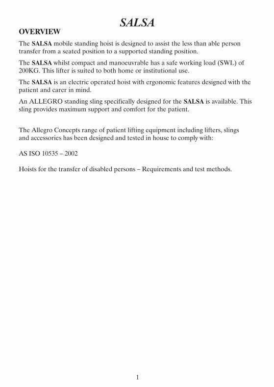
The SALSA mobile standing hoist is designed to assist the less than able person transfer from a seated position to a supported standing position
The SALSA whilst compact and manoeuvrable has a safe working load (SWL) of 200KG This lifter is suited to both home or institutional use
The SALSA is an electric operated hoist with ergonomic features designed with the patient and carer in mind
An ALLEGRO standing sling specifically designed for the SALSA is available This sling provides maximum support and comfort for the patient
The Allegro Concepts range of patient lifting equipment including lifters slings and accessories has been designed and tested in house to comply with
AS ISO 10535 ndash 2002
Hoists for the transfer of disabled persons ndash Requirements and test methods
1
SALSA SPECIFICATIONS
11
GK002LWS
1050mm
655mm
585mm
1035mm
ELECTRIC
125mm
825mm
1670mm
482KG
1200mm
REMOVABLE
BASE LENGTH
EXTERNAL BASE WIDTH
INTERNAL BASE WIDTH CLOSED
INTERNAL BASE WIDTH OPEN
BASE WIDTH ADJ
UNDER BED CLEARANCE
MIN HEIGHT OF LIFT ARM
MAX HEIGHT OF LIFT ARM
MACHINE WEIGHT
MINIMUM STORAGE HEIGHT
FOOTPLATE
IMPORTANT SAFETY CONSIDERATIONS
INTENDED USE OF THE PRODUCT
The SALSA compact mobile patient standingtransfer hoist has been designed to lift and transfer a less able person with the assistance of a carer
The SALSA should be used with one of the ALLEGRO range of patient slings as assessed by a competent trained person
NB Not all slings and accessories are compatible with this hoist
If you are unsure please contact ALLEGRO CONCEPTS
The correct and appropriate use of the SALSA hoist will reduce the risks associated with manual patient handling The liftingtransferring task should be assessed amp planned by a trained user
SAFETY CONSIDERATIONS
Ensure all that all users read this guide before operating the hoist
Do not operate the hoist without training in the safe operation of hoists amp slings IF IN DOUBT DO NOT USE
Only use slings which have been assessed as suitable by a competent trained professional
Read the relevant sling users guide which is provided with each sling before use
Do not use the hoist if there is any doubt about wear or damage to the unit
Do not use the hoist if there is any fraying or stitch damage to the sling or if the sling is damaged in any other way
DO NOT EXCEED THE SAFE WORKING LOAD OF THE HOIST (SALSA 200KG)
Ensure when the hoist is in use that the surrounding area is clear and the person being lifted is clear of all obstructing objects
THE SALSA STANDING TRANSFER HOIST IS NOT DESIGNED OR INTENDED TO USE WITH NON WEIGHT BEARING PATIENTS
2
TROUBLE SHOOTINGWARNING TROUBLE SHOOTING SHOULD ONLY BE CARRIED OUT BY
ALLEGRO CONCEPTS AUTHORISED PERSONNEL FAMILIAR WITHBOTH USE ELECTRICAL AND MECHANICAL FEATURES OF PATIENT
LIFTING HOISTS
The following is a guideline only to general trouble shooting
Before carrying out any trouble shooting ensure that
Red emergency stop button is released
Maintenance procedures checked amp followed
All cable connections are secure
Battery is fully charged
10
POSSIBLE FAULT
Warning buzzer soundswithin control box
Flat battery packFaulty battery pack
Recharge batteryReplace battery
Battery charger power indicatorLED does not light up
No mains connectionInternal fuse blown
Battery chargers is defective
Plug into mainsReplace fuse
Repair replace charger
Actuator will not run and no relayclick is heard from control box
Control box is defectiveHandset defective Replace control box
Actuator will not run via handsetbut control box relays click
Actuator plugs not fully pushedin to control box
Actuator defectiveControl box defective
Push firmly into correct portReplace actuator or control
Actuator cannot lift full load orruns slow
Batteries not chargeddefectiveLoad too high for lifter
Actuator motor damaged
Chargereplace batteriesReplace actuator
No response from control boxno clicking of relays is heard
Emergency stop button engagedHoist battery completely flatBlown fuse in battery pack
Faulty control box
ReleaseCharge battery
Replacerepair control box
Actuator works in onedirection only
Handset defectiveControl box defective
Replace handsetRepairreplace control box
ACTION
PUSH
LIFT ARMS
ACTUATOR
KNEE PAD
BATTERY PACK
LEG
HANDLE
3
GENERAL MAINTENANCETo prolong the working life of the lifter and for trouble free operation it isrecommended that periodic inspections should be performed routinely and as oftenas necessary Periodic inspections should be performed by a person who is suitablyqualified and well acquainted with the design use and care of patient lifting hoists
If inspection reveals that the safety of the hoist is jeopardised in any way the hoistshould be IMMEDIATELY WITHDRAWN FROM SERVICE tagged as such andthe owner notified
MAINTENANCE GUIDE amp CHECK LISTbull General visual inspection of lifter
bull Check castors are tightly attached to legs
bull Check castors run amp swivel freely remove any hair amp fluff from axle
bull Check castor brakes operate efficiently
bull Over haul castors amp pack with grease
bull Inspect surfaces for scratches amp chips
bull Clean surfacers with a neutral detergent remove any adhesive tape with orangeor eucalyptus oil
bull Examine all moving parts and fasteners for wear and fatigue lubricate and oradjust as required
bull NB leg pivot bushes incorporate a Teflon coated pivot bush which requiresminimal lubrication
bull Check tightness of bolt in leg bushes
bull Check linkages are secure in leg adjuster ball joints
bull Check all electrical components for correct operation
bull Check battery charger operation
bull Remove dirt amp dust from actuator
bull Wipe actuator shaft with oiled rag (DO NOT use WD40 or equivalent)bull Check mast to boom pivot point remove bolts and lightly regrease bush and
retighten ensuring free movement at pivot
A MAJOR SERVICE SHOULD BE CARRIED OUT EVERY 12 MONTHSAS A MINIMUM REQUIREMENT
IMPORTANT An annual load test to the safe working load(swl) is required forcompliance with AS ISO 10535 minus 2002
9
ASSEMBLY INSTRUCTION S SALSA 200 All the ALLEGRO range of patient lifting and transfer hoists are fully assembled load tested and certified at the factory before being partially dismantled for packing and shipping Use the instructions below as a guide to assemble your SALSA standing hoist 1 Remove lifter components from protective packing and lay out on a smooth
surface to prevent damage to powder coating on lifter sub assemblies 2 Remove mastleg chassis weldment and slide one leg into receiver clevis Align
bolt holes push bolt through clevis and leg bush Thread nylock nut onto bolt on the under side of leg and tighten Ensure thread engages nylon locking ring of nut
3 Repeat process 2 for second leg 4 Attach leg adjuster tie rod ends to each leg and tighten each nylock nut 5 Attach lift actuator to lifting arm assembly by aligning actuator clevis with
actuator mount bracket Insert bolt and tighten nylock nut 6 Attach push handle assembly with hex bolts and washers supplied with handle
assembly 7 Attach Linak control box to mount plate with M5 hex bolt then attach clip on
battery pack 8 Plug the lift actuator cable into port 1 and the leg adjust cable into port 2 of the
control box Both ports are located on the underside of the control box (diagram 1)
9 Ensure both plugs are pushed in firmly into their respective sockets
Diagram 1 10 Locate handset and push into handset socket ensuring alignment of tongue of
plug with keyway of socket Push home firmly A smear of Vaseline on the O ring may assist if plug is tight Check operation of the SALSA via handset ensuring that the RED EMERGENCY STOP BUTTON ON THE CONTROL BOX IS RELEASED Turn the knob ndash turn clockwise to release
4
LIFTING PROCEDURESbull Carer should be fully conversant and trained in the use of lifter and sling This
will decrease patient apprehension and increase their coshyoperation and overallsafety of the lifting process
bull Where possible always pull the lifter for maximum safety and comfort
bull Move the hoist slowly to avoid patient swing whilst standing
bull The hoist should not be used on ramps with incline greater than 5 deg
bull Never leave a patient in a sling unattended
bull Ensure brakes of the chair bed trolley that the patient is being lifted from arelocked
bull The braking castors on the lifter should be off This allows the lifter to create itsown centre of gravity (CG) over the weight of the patient NB This action mayresult in the lifter moving slightly during the initial phase of the lift
GENERAL LIFTING PROCEDUREThe information supplied below is not intended to be construed as a training
manual but as a general guide to lifting procedure only
bull The SALSA hoist utilises a special type of padded sling designed to fit around thepatients lower back It utilises a restraint belt to help prevent the sling fromslipping and riding up the patients back the restraint belt is adjustable and fastenswith either a buckle or a velcro flap around the chest area
bull Key hole buckles on the sling clip onto the studs located on both lift arms of thehoist
bull For detailed sling fitting instructions refer to COMFORT STANDING SLINGUSER MANUAL
bull NB THIS SLING SHOULD ONLY BE USED WITH THE SALSA HOISTAND MAY NOT BE COMPATIBLE WITH OTHER PATIENT HOISTS
bull Manoeuvre the hoist around the patient adjusting the legs to fit around chairwheel chair etc If lifting from a bed ensure under bed clearance is sufficient tomanoeuvre legs under the bed
bull Lower the SALSA lift arms using the handset buttons until sling keyhole bucklescan reach and easily engage the studs on the lift arms to prevent possible injuryensure the lift arms do not come in contact with patients face or body
bull Place keyhole buckles onto the correct stud on each lift arm and pull firmly toengae and lock A slight resistance should be felt as the buckle moves to the lockposition
bull Use the handset to raise the hoist boom enough to take up the patients weight Atthis point stop the lift Check all sling attachments are secure and that the sling ispositioned correctly Check patient comfort Lower and realign sling if necessary
8
HOIST OPERATION AND CHARGING HANDSET
The handset activates the lift actuator by the use of two low pressure buttons protected by a strong plastic cover These are symbolised by arrows (diagram) The arrows indicate the direction of travel to raise or lower the hoist jib When either button is released the jib will remain in position
Some versions of ALLEGRO hoists incorporate an actuator driven leg opening adjustment On these hoists two extra buttons will be seen on the handset with arrows and symbolised legs indicating the direction of travel This function allows an unrestricted range of leg adjustment
The handset is also fitted with a battery indicator light This will flash when the batteries reach a maximum discharge of 18 volts NB the light will only flash when the hoist is under load
The connection for the handset is located on the underside of the control box (diagram 1)
HANDSET ACTUATOR RELEASE
LEG ADJUST
ACTUATOR
The SALSA 200 mobile patient STANDINGTRANSFER hoist uses a LINAK single speed actuator with an emergency controlled lowering release handle( red lift up tab located at base of actuator shaft) This allows the patient to be lowered in the event of a fault in the hoist or deep discharged batteries
5
CHARGING DOs amp DONrsquoTs
DODo charge the battery whenever possible This will extend the battery life A largenumber of cycles can be obtained from operating on the batteries but batterylifetime is reduced with frequent discharging
Do inspect all cables particularly the mains power cable on the charger for anydamage replace where necessary
Do stow the handset and if fitted with charger the mains power cable whentransporting the hoist
Do clean the actuators control box charger battery and handset at regularintervals to remove dust and dirt
DONrsquoTDonrsquot allow the batteries to fully discharge before connecting to chargerThebatteries are a lead acid gel type that can be trickle charged continuously andhave a high current discharge capacity The batteries are not the nickel cadmiumtype and must not be periodically fully discharged Battery life is greatly reducedby deep or complete discharging of the batteries Longer lifetime is obtained bymaintaining fully charged batteries
7
CHARGING The SALSA is suppled with a LINAK external wall mount charger This is activated by plugging the 3 pin plug into a standard 240Vac outlet
To recharge the battery pack perform the following steps
bull Release battery pack from control box by pulling the handle on the pack towards youUse both hands to support the battery pack when removing or replacing it
bull Clip the battery pack onto the charging unit ensuring it is seated properly on the charger base
bull Charger will automatically activate charging sequence
CHARGING INDICATOR LIGHTS
GREEN mains power on light will be illuminated when connected to 240 v power supply
ORANGE LIGHT illuminated indicates battery currently charging
ORANGE LIGHT will extinguish when battery pack is fully charged
LINAK CHARGER UNIT
240V INPUT SOCKET
6
CHARGINGThe SALSA is suppled with a LINAK external wall mount charger This isactivated by plugging the 3 pin plug into a standard 240Vac outlet
To recharge the battery pack perform the following steps
bull Release battery pack from control box by pulling the handle on the pack towardsyouUse both hands to support the battery pack when removing or replacing it
bull Clip the battery pack onto the charging unit ensuring it is seated properly on thecharger base
bull Charger will automatically activate charging sequence
CHARGING INDICATOR LIGHTSGREEN mains power on light will be illuminated when connected to 240 v powersupply
ORANGE LIGHT illuminated indicates battery currently charging
ORANGE LIGHT will extinguish when battery pack is fully charged
LINAK CHARGER UNIT
240VINPUT SOCKET
6
CHARGING DOs amp DONrsquoTs
DO
Do charge the battery whenever possible This will extend the battery life A large number of cycles can be obtained from operating on the batteries but battery lifetime is reduced with frequent discharging
Do inspect all cables particularly the mains power cable on the charger for any damage replace where necessary
Do stow the handset and if fitted with charger the mains power cable when transporting the hoist
Do clean the actuators control box charger battery and handset at regular intervals to remove dust and dirt
DONrsquoT
Donrsquot allow the batteries to fully discharge before connecting to chargerThe batteries are a lead acid gel type that can be trickle charged continuously and have a high current discharge capacity The batteries are not the nickel cadmium type and must not be periodically fully discharged Battery life is greatly reduced by deep or complete discharging of the batteries Longer lifetime is obtained by maintaining fully charged batteries
7
HOIST OPERATION AND CHARGINGHANDSET
The handset activates the lift actuator by the use of two low pressure buttonsprotected by a strong plastic cover These are symbolised by arrows (diagram)The arrows indicate the direction of travel to raise or lower the hoist jib Wheneither button is released the jib will remain in position
Some versions of ALLEGRO hoists incorporate an actuator driven leg openingadjustment On these hoists two extra buttons will be seen on the handset witharrows and symbolised legs indicating the direction of travel This function allowsan unrestricted range of leg adjustment
The handset is also fitted with a battery indicator light This will flash when thebatteries reach a maximum discharge of 18 volts NB the light will only flashwhen the hoist is under load
The connection for the handset is located on the underside of the control box(diagram 1)
ACTUATORThe SALSA 200 mobile patient STANDINGTRANSFER hoist uses a LINAKsingle speed actuator with an emergency controlled lowering release handle( red liftup tab located at base of actuator shaft) This allows the patient to be lowered in theevent of a fault in the hoist or deep discharged batteries
HANDSET ACTUATOR RELEASE
LEG ADJUST
5
LIFTING PROCEDURES bull Carer should be fully conversant and trained in the use of lifter and sling This
will decrease patient apprehension and increase their coshyoperation and overall safety of the lifting process
bull Where possible always pull the lifter for maximum safety and comfort
bull Move the hoist slowly to avoid patient swing whilst standing
bull The hoist should not be used on ramps with incline greater than 5 deg
bull Never leave a patient in a sling unattended
bull Ensure brakes of the chair bed trolley that the patient is being lifted from are locked
bull The braking castors on the lifter should be off This allows the lifter to create its own centre of gravity (CG) over the weight of the patient NB This action may result in the lifter moving slightly during the initial phase of the lift
GENERAL LIFTING PROCEDURE
The information supplied below is not intended to be construed as a training manual but as a general guide to lifting procedure only
bull The SALSA hoist utilises a special type of padded sling designed to fit around the patients lower back It utilises a restraint belt to help prevent the sling from slipping and riding up the patients back the restraint belt is adjustable and fastens with either a buckle or a velcro flap around the chest area
bull Key hole buckles on the sling clip onto the studs located on both lift arms of the hoist
bull For detailed sling fitting instructions refer to COMFORT STANDING SLING USER MANUAL
bull NB THIS SLING SHOULD ONLY BE USED WITH THE SALSA HOIST AND MAY NOT BE COMPATIBLE WITH OTHER PATIENT HOISTS
bull Manoeuvre the hoist around the patient adjusting the legs to fit around chair wheel chair etc If lifting from a bed ensure under bed clearance is sufficient to manoeuvre legs under the bed
bull Lower the SALSA lift arms using the handset buttons until sling keyhole buckles can reach and easily engage the studs on the lift arms to prevent possible injury ensure the lift arms do not come in contact with patients face or body
bull Place keyhole buckles onto the correct stud on each lift arm and pull firmly to engae and lock A slight resistance should be felt as the buckle moves to the lock position
bull Use the handset to raise the hoist boom enough to take up the patients weight At this point stop the lift Check all sling attachments are secure and that the sling is positioned correctly Check patient comfort Lower and realign sling if necessary
8
4
ASSEMBLY INSTRUCTION SSALSA 200All the ALLEGRO range of patient lifting and transfer hoists are fully assembledload tested and certified at the factory before being partially dismantled for packingand shippingUse the instructions below as a guide to assemble your SALSA standing hoist1 Remove lifter components from protective packing and lay out on a smooth
surface to prevent damage to powder coating on lifter sub assemblies2 Remove mastleg chassis weldment and slide one leg into receiver clevis Align
bolt holes push bolt through clevis and leg bush Thread nylock nut onto bolton the under side of leg and tighten Ensure thread engages nylon locking ringof nut
3 Repeat process 2 for second leg4 Attach leg adjuster tie rod ends to each leg and tighten each nylock nut5 Attach lift actuator to lifting arm assembly by aligning actuator clevis with
actuator mount bracket Insert bolt and tighten nylock nut6 Attach push handle assembly with hex bolts and washers supplied with handle
assembly7 Attach Linak control box to mount plate with M5 hex bolt then attach clip on
battery pack8 Plug the lift actuator cable into port 1 and the leg adjust cable into port 2 of the
control box Both ports are located on the underside of the control box(diagram 1)
9 Ensure both plugs are pushed in firmly into their respective sockets
Diagram 110 Locate handset and push into handset socket ensuring alignment of tongue of
plug with keyway of socket Push home firmly A smear of Vaseline on the Oring may assist if plug is tight Check operation of the SALSA via handsetensuring that the RED EMERGENCY STOP BUTTON ON THE CONTROLBOX IS RELEASED Turn the knob ndash turn clockwise to release
GENERAL MAINTENANCE To prolong the working life of the lifter and for trouble free operation it is recommended that periodic inspections should be performed routinely and as often as necessary Periodic inspections should be performed by a person who is suitably qualified and well acquainted with the design use and care of patient lifting hoists
If inspection reveals that the safety of the hoist is jeopardised in any way the hoist should be IMMEDIATELY WITHDRAWN FROM SERVICE tagged as such and the owner notified
MAINTENANCE GUIDE amp CHECK LIST bull General visual inspection of lifter
bull Check castors are tightly attached to legs
bull Check castors run amp swivel freely remove any hair amp fluff from axle
bull Check castor brakes operate efficiently
bull Over haul castors amp pack with grease
bull Inspect surfaces for scratches amp chips
bull Clean surfacers with a neutral detergent remove any adhesive tape with orange or eucalyptus oil
bull Examine all moving parts and fasteners for wear and fatigue lubricate and or adjust as required
bull NB leg pivot bushes incorporate a Teflon coated pivot bush which requires minimal lubrication
bull Check tightness of bolt in leg bushes
bull Check linkages are secure in leg adjuster ball joints
bull Check all electrical components for correct operation
bull Check battery charger operation
bull Remove dirt amp dust from actuator
bull Wipe actuator shaft with oiled rag (DO NOT use WD40 or equivalent) bull Check mast to boom pivot point remove bolts and lightly regrease bush and
retighten ensuring free movement at pivot
A MAJOR SERVICE SHOULD BE CARRIED OUT EVERY 12 MONTHS AS A MINIMUM REQUIREMENT
IMPORTANT An annual load test to the safe working load(swl) is required for compliance with AS ISO 10535 minus 2002
9
3
PUSHHANDLE
LIFT ARMS
ACTUATOR
KNEE PAD
BATTERYPACK
LEG
TROUBLE SHOOTING
WARNING TROUBLE SHOOTING SHOULD ONLY BE CARRIED OUT BY ALLEGRO CONCEPTS AUTHORISED PERSONNEL FAMILIAR WITH
BOTH USE ELECTRICAL AND MECHANICAL FEATURES OF PATIENT LIFTING HOISTS
The following is a guideline only to general trouble shooting
Before carrying out any trouble shooting ensure that
Red emergency stop button is released
Maintenance procedures checked amp followed
All cable connections are secure
Battery is fully charged
POSSIBLE FAULT ACTION
Warning buzzer sounds within control box
Flat battery pack Faulty battery pack
Recharge battery Replace battery
Battery charger power indicator LED does not light up
No mains connection Internal fuse blown
Battery chargers is defective
Plug into mains Replace fuse
Repair replace charger
Actuator will not run and no relay click is heard from control box
Control box is defective Handset defective Replace control box
Actuator will not run via handset but control box relays click
Actuator plugs not fully pushed in to control box
Actuator defective Control box defective
Push firmly into correct port Replace actuator or control
Actuator cannot lift full load or runs slow
Batteries not chargeddefective Load too high for lifter
Actuator motor damaged
Chargereplace batteries Replace actuator
No response from control box no clicking of relays is heard
Emergency stop button engaged Hoist battery completely flat Blown fuse in battery pack
Faulty control box
Release Charge battery
Replacerepair control box
Actuator works in one direction only
Handset defective Control box defective
Replace handset Repairreplace control box
10
IMPORTANT SAFETY CONSIDERATIONS
INTENDED USE OF THE PRODUCTThe SALSA compact mobile patient standingtransfer hoist has been designed to liftand transfer a less able person with the assistance of a carer
The SALSA should be used with one of the ALLEGRO range of patient slings asassessed by a competent trained person
NB Not all slings and accessories are compatible with this hoist
If you are unsure please contact ALLEGRO CONCEPTS
The correct and appropriate use of the SALSA hoist will reduce the risks associatedwith manual patient handling The liftingtransferring task should be assessed ampplanned by a trained user
SAFETY CONSIDERATIONSEnsure all that all users read this guide before operating the hoist
Do not operate the hoist without training in the safe operation of hoists amp slingsIF IN DOUBT DO NOT USE
Only use slings which have been assessed as suitable by a competent trainedprofessional
Read the relevant sling users guide which is provided with each sling before use
Do not use the hoist if there is any doubt about wear or damage to the unit
Do not use the hoist if there is any fraying or stitch damage to the sling or if thesling is damaged in any other way
DO NOT EXCEED THE SAFE WORKING LOAD OF THE HOIST(SALSA 200KG)
Ensure when the hoist is in use that the surrounding area is clear and the personbeing lifted is clear of all obstructing objects
THE SALSA STANDING TRANSFER HOIST IS NOT DESIGNED OR INTENDEDTO USE WITH NON WEIGHT BEARING PATIENTS
2
SALSA SPECIFICATIONS
SWL 200KG
BASE LENGTH 1050mm
EXTERNAL BASE WIDTH 655mm
INTERNAL BASE WIDTH CLOSED 585mm
INTERNAL BASE WIDTH OPEN 1035mm
BASE WIDTH ADJ ELECTRIC
UNDER BED CLEARANCE 125mm
MIN HEIGHT OF LIFT ARM 825mm
MAX HEIGHT OF LIFT ARM 1670mm
MACHINE WEIGHT 482KG
MINIMUM STORAGE HEIGHT 1200mm
FOOTPLATE REMOVABLE
11
SALSAOVERVIEWThe SALSA mobile standing hoist is designed to assist the less than able persontransfer from a seated position to a supported standing position
The SALSA whilst compact and manoeuvrable has a safe working load (SWL) of200KG This lifter is suited to both home or institutional use
The SALSA is an electric operated hoist with ergonomic features designed with thepatient and carer in mind
An ALLEGRO standing sling specifically designed for the SALSA is available Thissling provides maximum support and comfort for the patient
1
The Allegro Concepts range of patient lifting equipment including lifters slings and accessories has been designed and tested in house to comply with
AS ISO 10535 ndash 2002
Hoists for the transfer of disabled persons ndash Requirements and test methods
WARRANTY ALLEGRO CONCEPTS PTY LTD warrants its products to be free from defects in materials and workmanship under normal use and service and will within the period stated below from the date of purchase repair or replace without cost to the original customer any part assembly or portion thereof which shall be returned to ALLEGRO CONCEPTS and from OUR inspection shows to be defective
Patient lifter including electronics 2 years
Accessories on lifter 2 years
Patient slings 1 year
Weighing devices 1 year
Batteries 3 months
ALLEGRO CONCEPTS PTY LTD cannot be held responsible for any personal injury damage to the hoist or damage to property as a result of the improper or unsafe use of the product
No warranty claim shall apply where the product or any part thereof has been modified varied altered or damaged either accidentally or through improper or negligent use
No warranty claim shall apply where the hoist is repaired or serviced by any persons not accredited by the authorised distributor
Warranty does not extend to items or components which may require replacement due to normal wear and tear ( eg castors mouldings and paint work ) for which ALLEGRO CONCEPTS nor its distributors can be held responsible
BATTERIES
Batteries carry a limited warranty from the original manufacturer which is subject to a stringent wear and tear clause Any battery faults due to defect in original manufacture will normally become apparent within the first two months of use
Any gradual deterioration in performance after this period is normally associated with fair wear and tear misuse and accidental damage and as such is not covered by the manufacturers warranty
12
CONTENTS
SALSA LIFT 200 OVERVIEW 1
IMPORTANT SAFETY CONSIDERATIONS 2
SALSA LIFT 200 ASSEMBLY INSTRUCTIONS 3
HOIST OPERATION AND CHARGING 5
LIFTING PROCEDURES 8
MAINTENANCE 9
TROUBLE SHOOTING 10
SPECIFICATIONS 11
WARRANTY 12
LOG BOOK 13
LOG BOOK
SERVICE TYPE CONDITION REPORT
DATE
INSPECTED BY
SIGNATURE ACTION TAKEN
SERVICE TYPE CONDITION REPORT
DATE
INSPECTED BY
SIGNATURE ACTION TAKEN
13
SALSAMOBILE STANDING TRANSFER HOIST
IMPORTANTDO NOT USE THE SALSA STANDING TRANSFER
LIFTER WITHOUT HAVING FIRST READ THISMANUAL
DISTRIBUTED BY
13
LOG BOOK
SERVICE TYPE
DATE
INSPECTED BY
NEKATNOITCAERUTANGIS
CONDITION REPORT
SERVICE TYPE
DATE
INSPECTED BY
NEKATNOITCAERUTANGIS
CONDITION REPORT
1
2
CONTENTS
SALSA LIFT 200 OVERVIEW
IMPORTANT SAFETY CONSIDERATIONS
SALSA LIFT 200 ASSEMBLY INSTRUCTIONS
HOIST OPERATION AND CHARGING
LIFTING PROCEDURES
MAINTENANCE
TROUBLE SHOOTING
SPECIFICATIONS
WARRANTY
LOG BOOK
3
5
8
9
10
11
12
13
WARRANTYALLEGRO CONCEPTS PTY LTD warrants its products to be free from defects inmaterials and workmanship under normal use and service and will within the periodstated below from the date of purchase repair or replace without cost to theoriginal customer any part assembly or portion thereof which shall be returned toALLEGRO CONCEPTS and from OUR inspection shows to be defective
Patient lifter including electronics 2 years
Accessories on lifter 2 years
raey1sgnilstneitaP
raey1secivedgnihgieW
shtnom3seirettaB
ALLEGRO CONCEPTS PTY LTD cannot be held responsible for any personalinjury damage to the hoist or damage to property as a result of the improper orunsafe use of the product
No warranty claim shall apply where the product or any part thereof has beenmodified varied altered or damaged either accidentally or through improper ornegligent use
No warranty claim shall apply where the hoist is repaired or serviced by any personsnot accredited by the authorised distributor
Warranty does not extend to items or components which may require replacementdue to normal wear and tear ( eg castors mouldings and paint work ) for whichALLEGRO CONCEPTS nor its distributors can be held responsible
BATTERIESBatteries carry a limited warranty from the original manufacturer which is subject toa stringent wear and tear clause Any battery faults due to defect in originalmanufacture will normally become apparent within the first two months of use
Any gradual deterioration in performance after this period is normally associatedwith fair wear and tear misuse and accidental damage and as such is not covered bythe manufacturers warranty
12
SALSA OVERVIEW
The SALSA mobile standing hoist is designed to assist the less than able person transfer from a seated position to a supported standing position
The SALSA whilst compact and manoeuvrable has a safe working load (SWL) of 200KG This lifter is suited to both home or institutional use
The SALSA is an electric operated hoist with ergonomic features designed with the patient and carer in mind
An ALLEGRO standing sling specifically designed for the SALSA is available This sling provides maximum support and comfort for the patient
The Allegro Concepts range of patient lifting equipment including lifters slings and accessories has been designed and tested in house to comply with
AS ISO 10535 ndash 2002
Hoists for the transfer of disabled persons ndash Requirements and test methods
1
SALSA SPECIFICATIONS
11
GK002LWS
1050mm
655mm
585mm
1035mm
ELECTRIC
125mm
825mm
1670mm
482KG
1200mm
REMOVABLE
BASE LENGTH
EXTERNAL BASE WIDTH
INTERNAL BASE WIDTH CLOSED
INTERNAL BASE WIDTH OPEN
BASE WIDTH ADJ
UNDER BED CLEARANCE
MIN HEIGHT OF LIFT ARM
MAX HEIGHT OF LIFT ARM
MACHINE WEIGHT
MINIMUM STORAGE HEIGHT
FOOTPLATE
IMPORTANT SAFETY CONSIDERATIONS
INTENDED USE OF THE PRODUCT
The SALSA compact mobile patient standingtransfer hoist has been designed to lift and transfer a less able person with the assistance of a carer
The SALSA should be used with one of the ALLEGRO range of patient slings as assessed by a competent trained person
NB Not all slings and accessories are compatible with this hoist
If you are unsure please contact ALLEGRO CONCEPTS
The correct and appropriate use of the SALSA hoist will reduce the risks associated with manual patient handling The liftingtransferring task should be assessed amp planned by a trained user
SAFETY CONSIDERATIONS
Ensure all that all users read this guide before operating the hoist
Do not operate the hoist without training in the safe operation of hoists amp slings IF IN DOUBT DO NOT USE
Only use slings which have been assessed as suitable by a competent trained professional
Read the relevant sling users guide which is provided with each sling before use
Do not use the hoist if there is any doubt about wear or damage to the unit
Do not use the hoist if there is any fraying or stitch damage to the sling or if the sling is damaged in any other way
DO NOT EXCEED THE SAFE WORKING LOAD OF THE HOIST (SALSA 200KG)
Ensure when the hoist is in use that the surrounding area is clear and the person being lifted is clear of all obstructing objects
THE SALSA STANDING TRANSFER HOIST IS NOT DESIGNED OR INTENDED TO USE WITH NON WEIGHT BEARING PATIENTS
2
TROUBLE SHOOTINGWARNING TROUBLE SHOOTING SHOULD ONLY BE CARRIED OUT BY
ALLEGRO CONCEPTS AUTHORISED PERSONNEL FAMILIAR WITHBOTH USE ELECTRICAL AND MECHANICAL FEATURES OF PATIENT
LIFTING HOISTS
The following is a guideline only to general trouble shooting
Before carrying out any trouble shooting ensure that
Red emergency stop button is released
Maintenance procedures checked amp followed
All cable connections are secure
Battery is fully charged
10
POSSIBLE FAULT
Warning buzzer soundswithin control box
Flat battery packFaulty battery pack
Recharge batteryReplace battery
Battery charger power indicatorLED does not light up
No mains connectionInternal fuse blown
Battery chargers is defective
Plug into mainsReplace fuse
Repair replace charger
Actuator will not run and no relayclick is heard from control box
Control box is defectiveHandset defective Replace control box
Actuator will not run via handsetbut control box relays click
Actuator plugs not fully pushedin to control box
Actuator defectiveControl box defective
Push firmly into correct portReplace actuator or control
Actuator cannot lift full load orruns slow
Batteries not chargeddefectiveLoad too high for lifter
Actuator motor damaged
Chargereplace batteriesReplace actuator
No response from control boxno clicking of relays is heard
Emergency stop button engagedHoist battery completely flatBlown fuse in battery pack
Faulty control box
ReleaseCharge battery
Replacerepair control box
Actuator works in onedirection only
Handset defectiveControl box defective
Replace handsetRepairreplace control box
ACTION
PUSH
LIFT ARMS
ACTUATOR
KNEE PAD
BATTERY PACK
LEG
HANDLE
3
GENERAL MAINTENANCETo prolong the working life of the lifter and for trouble free operation it isrecommended that periodic inspections should be performed routinely and as oftenas necessary Periodic inspections should be performed by a person who is suitablyqualified and well acquainted with the design use and care of patient lifting hoists
If inspection reveals that the safety of the hoist is jeopardised in any way the hoistshould be IMMEDIATELY WITHDRAWN FROM SERVICE tagged as such andthe owner notified
MAINTENANCE GUIDE amp CHECK LISTbull General visual inspection of lifter
bull Check castors are tightly attached to legs
bull Check castors run amp swivel freely remove any hair amp fluff from axle
bull Check castor brakes operate efficiently
bull Over haul castors amp pack with grease
bull Inspect surfaces for scratches amp chips
bull Clean surfacers with a neutral detergent remove any adhesive tape with orangeor eucalyptus oil
bull Examine all moving parts and fasteners for wear and fatigue lubricate and oradjust as required
bull NB leg pivot bushes incorporate a Teflon coated pivot bush which requiresminimal lubrication
bull Check tightness of bolt in leg bushes
bull Check linkages are secure in leg adjuster ball joints
bull Check all electrical components for correct operation
bull Check battery charger operation
bull Remove dirt amp dust from actuator
bull Wipe actuator shaft with oiled rag (DO NOT use WD40 or equivalent)bull Check mast to boom pivot point remove bolts and lightly regrease bush and
retighten ensuring free movement at pivot
A MAJOR SERVICE SHOULD BE CARRIED OUT EVERY 12 MONTHSAS A MINIMUM REQUIREMENT
IMPORTANT An annual load test to the safe working load(swl) is required forcompliance with AS ISO 10535 minus 2002
9
ASSEMBLY INSTRUCTION S SALSA 200 All the ALLEGRO range of patient lifting and transfer hoists are fully assembled load tested and certified at the factory before being partially dismantled for packing and shipping Use the instructions below as a guide to assemble your SALSA standing hoist 1 Remove lifter components from protective packing and lay out on a smooth
surface to prevent damage to powder coating on lifter sub assemblies 2 Remove mastleg chassis weldment and slide one leg into receiver clevis Align
bolt holes push bolt through clevis and leg bush Thread nylock nut onto bolt on the under side of leg and tighten Ensure thread engages nylon locking ring of nut
3 Repeat process 2 for second leg 4 Attach leg adjuster tie rod ends to each leg and tighten each nylock nut 5 Attach lift actuator to lifting arm assembly by aligning actuator clevis with
actuator mount bracket Insert bolt and tighten nylock nut 6 Attach push handle assembly with hex bolts and washers supplied with handle
assembly 7 Attach Linak control box to mount plate with M5 hex bolt then attach clip on
battery pack 8 Plug the lift actuator cable into port 1 and the leg adjust cable into port 2 of the
control box Both ports are located on the underside of the control box (diagram 1)
9 Ensure both plugs are pushed in firmly into their respective sockets
Diagram 1 10 Locate handset and push into handset socket ensuring alignment of tongue of
plug with keyway of socket Push home firmly A smear of Vaseline on the O ring may assist if plug is tight Check operation of the SALSA via handset ensuring that the RED EMERGENCY STOP BUTTON ON THE CONTROL BOX IS RELEASED Turn the knob ndash turn clockwise to release
4
LIFTING PROCEDURESbull Carer should be fully conversant and trained in the use of lifter and sling This
will decrease patient apprehension and increase their coshyoperation and overallsafety of the lifting process
bull Where possible always pull the lifter for maximum safety and comfort
bull Move the hoist slowly to avoid patient swing whilst standing
bull The hoist should not be used on ramps with incline greater than 5 deg
bull Never leave a patient in a sling unattended
bull Ensure brakes of the chair bed trolley that the patient is being lifted from arelocked
bull The braking castors on the lifter should be off This allows the lifter to create itsown centre of gravity (CG) over the weight of the patient NB This action mayresult in the lifter moving slightly during the initial phase of the lift
GENERAL LIFTING PROCEDUREThe information supplied below is not intended to be construed as a training
manual but as a general guide to lifting procedure only
bull The SALSA hoist utilises a special type of padded sling designed to fit around thepatients lower back It utilises a restraint belt to help prevent the sling fromslipping and riding up the patients back the restraint belt is adjustable and fastenswith either a buckle or a velcro flap around the chest area
bull Key hole buckles on the sling clip onto the studs located on both lift arms of thehoist
bull For detailed sling fitting instructions refer to COMFORT STANDING SLINGUSER MANUAL
bull NB THIS SLING SHOULD ONLY BE USED WITH THE SALSA HOISTAND MAY NOT BE COMPATIBLE WITH OTHER PATIENT HOISTS
bull Manoeuvre the hoist around the patient adjusting the legs to fit around chairwheel chair etc If lifting from a bed ensure under bed clearance is sufficient tomanoeuvre legs under the bed
bull Lower the SALSA lift arms using the handset buttons until sling keyhole bucklescan reach and easily engage the studs on the lift arms to prevent possible injuryensure the lift arms do not come in contact with patients face or body
bull Place keyhole buckles onto the correct stud on each lift arm and pull firmly toengae and lock A slight resistance should be felt as the buckle moves to the lockposition
bull Use the handset to raise the hoist boom enough to take up the patients weight Atthis point stop the lift Check all sling attachments are secure and that the sling ispositioned correctly Check patient comfort Lower and realign sling if necessary
8
HOIST OPERATION AND CHARGING HANDSET
The handset activates the lift actuator by the use of two low pressure buttons protected by a strong plastic cover These are symbolised by arrows (diagram) The arrows indicate the direction of travel to raise or lower the hoist jib When either button is released the jib will remain in position
Some versions of ALLEGRO hoists incorporate an actuator driven leg opening adjustment On these hoists two extra buttons will be seen on the handset with arrows and symbolised legs indicating the direction of travel This function allows an unrestricted range of leg adjustment
The handset is also fitted with a battery indicator light This will flash when the batteries reach a maximum discharge of 18 volts NB the light will only flash when the hoist is under load
The connection for the handset is located on the underside of the control box (diagram 1)
HANDSET ACTUATOR RELEASE
LEG ADJUST
ACTUATOR
The SALSA 200 mobile patient STANDINGTRANSFER hoist uses a LINAK single speed actuator with an emergency controlled lowering release handle( red lift up tab located at base of actuator shaft) This allows the patient to be lowered in the event of a fault in the hoist or deep discharged batteries
5
CHARGING DOs amp DONrsquoTs
DODo charge the battery whenever possible This will extend the battery life A largenumber of cycles can be obtained from operating on the batteries but batterylifetime is reduced with frequent discharging
Do inspect all cables particularly the mains power cable on the charger for anydamage replace where necessary
Do stow the handset and if fitted with charger the mains power cable whentransporting the hoist
Do clean the actuators control box charger battery and handset at regularintervals to remove dust and dirt
DONrsquoTDonrsquot allow the batteries to fully discharge before connecting to chargerThebatteries are a lead acid gel type that can be trickle charged continuously andhave a high current discharge capacity The batteries are not the nickel cadmiumtype and must not be periodically fully discharged Battery life is greatly reducedby deep or complete discharging of the batteries Longer lifetime is obtained bymaintaining fully charged batteries
7
CHARGING The SALSA is suppled with a LINAK external wall mount charger This is activated by plugging the 3 pin plug into a standard 240Vac outlet
To recharge the battery pack perform the following steps
bull Release battery pack from control box by pulling the handle on the pack towards youUse both hands to support the battery pack when removing or replacing it
bull Clip the battery pack onto the charging unit ensuring it is seated properly on the charger base
bull Charger will automatically activate charging sequence
CHARGING INDICATOR LIGHTS
GREEN mains power on light will be illuminated when connected to 240 v power supply
ORANGE LIGHT illuminated indicates battery currently charging
ORANGE LIGHT will extinguish when battery pack is fully charged
LINAK CHARGER UNIT
240V INPUT SOCKET
6
CHARGINGThe SALSA is suppled with a LINAK external wall mount charger This isactivated by plugging the 3 pin plug into a standard 240Vac outlet
To recharge the battery pack perform the following steps
bull Release battery pack from control box by pulling the handle on the pack towardsyouUse both hands to support the battery pack when removing or replacing it
bull Clip the battery pack onto the charging unit ensuring it is seated properly on thecharger base
bull Charger will automatically activate charging sequence
CHARGING INDICATOR LIGHTSGREEN mains power on light will be illuminated when connected to 240 v powersupply
ORANGE LIGHT illuminated indicates battery currently charging
ORANGE LIGHT will extinguish when battery pack is fully charged
LINAK CHARGER UNIT
240VINPUT SOCKET
6
CHARGING DOs amp DONrsquoTs
DO
Do charge the battery whenever possible This will extend the battery life A large number of cycles can be obtained from operating on the batteries but battery lifetime is reduced with frequent discharging
Do inspect all cables particularly the mains power cable on the charger for any damage replace where necessary
Do stow the handset and if fitted with charger the mains power cable when transporting the hoist
Do clean the actuators control box charger battery and handset at regular intervals to remove dust and dirt
DONrsquoT
Donrsquot allow the batteries to fully discharge before connecting to chargerThe batteries are a lead acid gel type that can be trickle charged continuously and have a high current discharge capacity The batteries are not the nickel cadmium type and must not be periodically fully discharged Battery life is greatly reduced by deep or complete discharging of the batteries Longer lifetime is obtained by maintaining fully charged batteries
7
HOIST OPERATION AND CHARGINGHANDSET
The handset activates the lift actuator by the use of two low pressure buttonsprotected by a strong plastic cover These are symbolised by arrows (diagram)The arrows indicate the direction of travel to raise or lower the hoist jib Wheneither button is released the jib will remain in position
Some versions of ALLEGRO hoists incorporate an actuator driven leg openingadjustment On these hoists two extra buttons will be seen on the handset witharrows and symbolised legs indicating the direction of travel This function allowsan unrestricted range of leg adjustment
The handset is also fitted with a battery indicator light This will flash when thebatteries reach a maximum discharge of 18 volts NB the light will only flashwhen the hoist is under load
The connection for the handset is located on the underside of the control box(diagram 1)
ACTUATORThe SALSA 200 mobile patient STANDINGTRANSFER hoist uses a LINAKsingle speed actuator with an emergency controlled lowering release handle( red liftup tab located at base of actuator shaft) This allows the patient to be lowered in theevent of a fault in the hoist or deep discharged batteries
HANDSET ACTUATOR RELEASE
LEG ADJUST
5
LIFTING PROCEDURES bull Carer should be fully conversant and trained in the use of lifter and sling This
will decrease patient apprehension and increase their coshyoperation and overall safety of the lifting process
bull Where possible always pull the lifter for maximum safety and comfort
bull Move the hoist slowly to avoid patient swing whilst standing
bull The hoist should not be used on ramps with incline greater than 5 deg
bull Never leave a patient in a sling unattended
bull Ensure brakes of the chair bed trolley that the patient is being lifted from are locked
bull The braking castors on the lifter should be off This allows the lifter to create its own centre of gravity (CG) over the weight of the patient NB This action may result in the lifter moving slightly during the initial phase of the lift
GENERAL LIFTING PROCEDURE
The information supplied below is not intended to be construed as a training manual but as a general guide to lifting procedure only
bull The SALSA hoist utilises a special type of padded sling designed to fit around the patients lower back It utilises a restraint belt to help prevent the sling from slipping and riding up the patients back the restraint belt is adjustable and fastens with either a buckle or a velcro flap around the chest area
bull Key hole buckles on the sling clip onto the studs located on both lift arms of the hoist
bull For detailed sling fitting instructions refer to COMFORT STANDING SLING USER MANUAL
bull NB THIS SLING SHOULD ONLY BE USED WITH THE SALSA HOIST AND MAY NOT BE COMPATIBLE WITH OTHER PATIENT HOISTS
bull Manoeuvre the hoist around the patient adjusting the legs to fit around chair wheel chair etc If lifting from a bed ensure under bed clearance is sufficient to manoeuvre legs under the bed
bull Lower the SALSA lift arms using the handset buttons until sling keyhole buckles can reach and easily engage the studs on the lift arms to prevent possible injury ensure the lift arms do not come in contact with patients face or body
bull Place keyhole buckles onto the correct stud on each lift arm and pull firmly to engae and lock A slight resistance should be felt as the buckle moves to the lock position
bull Use the handset to raise the hoist boom enough to take up the patients weight At this point stop the lift Check all sling attachments are secure and that the sling is positioned correctly Check patient comfort Lower and realign sling if necessary
8
4
ASSEMBLY INSTRUCTION SSALSA 200All the ALLEGRO range of patient lifting and transfer hoists are fully assembledload tested and certified at the factory before being partially dismantled for packingand shippingUse the instructions below as a guide to assemble your SALSA standing hoist1 Remove lifter components from protective packing and lay out on a smooth
surface to prevent damage to powder coating on lifter sub assemblies2 Remove mastleg chassis weldment and slide one leg into receiver clevis Align
bolt holes push bolt through clevis and leg bush Thread nylock nut onto bolton the under side of leg and tighten Ensure thread engages nylon locking ringof nut
3 Repeat process 2 for second leg4 Attach leg adjuster tie rod ends to each leg and tighten each nylock nut5 Attach lift actuator to lifting arm assembly by aligning actuator clevis with
actuator mount bracket Insert bolt and tighten nylock nut6 Attach push handle assembly with hex bolts and washers supplied with handle
assembly7 Attach Linak control box to mount plate with M5 hex bolt then attach clip on
battery pack8 Plug the lift actuator cable into port 1 and the leg adjust cable into port 2 of the
control box Both ports are located on the underside of the control box(diagram 1)
9 Ensure both plugs are pushed in firmly into their respective sockets
Diagram 110 Locate handset and push into handset socket ensuring alignment of tongue of
plug with keyway of socket Push home firmly A smear of Vaseline on the Oring may assist if plug is tight Check operation of the SALSA via handsetensuring that the RED EMERGENCY STOP BUTTON ON THE CONTROLBOX IS RELEASED Turn the knob ndash turn clockwise to release
GENERAL MAINTENANCE To prolong the working life of the lifter and for trouble free operation it is recommended that periodic inspections should be performed routinely and as often as necessary Periodic inspections should be performed by a person who is suitably qualified and well acquainted with the design use and care of patient lifting hoists
If inspection reveals that the safety of the hoist is jeopardised in any way the hoist should be IMMEDIATELY WITHDRAWN FROM SERVICE tagged as such and the owner notified
MAINTENANCE GUIDE amp CHECK LIST bull General visual inspection of lifter
bull Check castors are tightly attached to legs
bull Check castors run amp swivel freely remove any hair amp fluff from axle
bull Check castor brakes operate efficiently
bull Over haul castors amp pack with grease
bull Inspect surfaces for scratches amp chips
bull Clean surfacers with a neutral detergent remove any adhesive tape with orange or eucalyptus oil
bull Examine all moving parts and fasteners for wear and fatigue lubricate and or adjust as required
bull NB leg pivot bushes incorporate a Teflon coated pivot bush which requires minimal lubrication
bull Check tightness of bolt in leg bushes
bull Check linkages are secure in leg adjuster ball joints
bull Check all electrical components for correct operation
bull Check battery charger operation
bull Remove dirt amp dust from actuator
bull Wipe actuator shaft with oiled rag (DO NOT use WD40 or equivalent) bull Check mast to boom pivot point remove bolts and lightly regrease bush and
retighten ensuring free movement at pivot
A MAJOR SERVICE SHOULD BE CARRIED OUT EVERY 12 MONTHS AS A MINIMUM REQUIREMENT
IMPORTANT An annual load test to the safe working load(swl) is required for compliance with AS ISO 10535 minus 2002
9
3
PUSHHANDLE
LIFT ARMS
ACTUATOR
KNEE PAD
BATTERYPACK
LEG
TROUBLE SHOOTING
WARNING TROUBLE SHOOTING SHOULD ONLY BE CARRIED OUT BY ALLEGRO CONCEPTS AUTHORISED PERSONNEL FAMILIAR WITH
BOTH USE ELECTRICAL AND MECHANICAL FEATURES OF PATIENT LIFTING HOISTS
The following is a guideline only to general trouble shooting
Before carrying out any trouble shooting ensure that
Red emergency stop button is released
Maintenance procedures checked amp followed
All cable connections are secure
Battery is fully charged
POSSIBLE FAULT ACTION
Warning buzzer sounds within control box
Flat battery pack Faulty battery pack
Recharge battery Replace battery
Battery charger power indicator LED does not light up
No mains connection Internal fuse blown
Battery chargers is defective
Plug into mains Replace fuse
Repair replace charger
Actuator will not run and no relay click is heard from control box
Control box is defective Handset defective Replace control box
Actuator will not run via handset but control box relays click
Actuator plugs not fully pushed in to control box
Actuator defective Control box defective
Push firmly into correct port Replace actuator or control
Actuator cannot lift full load or runs slow
Batteries not chargeddefective Load too high for lifter
Actuator motor damaged
Chargereplace batteries Replace actuator
No response from control box no clicking of relays is heard
Emergency stop button engaged Hoist battery completely flat Blown fuse in battery pack
Faulty control box
Release Charge battery
Replacerepair control box
Actuator works in one direction only
Handset defective Control box defective
Replace handset Repairreplace control box
10
IMPORTANT SAFETY CONSIDERATIONS
INTENDED USE OF THE PRODUCTThe SALSA compact mobile patient standingtransfer hoist has been designed to liftand transfer a less able person with the assistance of a carer
The SALSA should be used with one of the ALLEGRO range of patient slings asassessed by a competent trained person
NB Not all slings and accessories are compatible with this hoist
If you are unsure please contact ALLEGRO CONCEPTS
The correct and appropriate use of the SALSA hoist will reduce the risks associatedwith manual patient handling The liftingtransferring task should be assessed ampplanned by a trained user
SAFETY CONSIDERATIONSEnsure all that all users read this guide before operating the hoist
Do not operate the hoist without training in the safe operation of hoists amp slingsIF IN DOUBT DO NOT USE
Only use slings which have been assessed as suitable by a competent trainedprofessional
Read the relevant sling users guide which is provided with each sling before use
Do not use the hoist if there is any doubt about wear or damage to the unit
Do not use the hoist if there is any fraying or stitch damage to the sling or if thesling is damaged in any other way
DO NOT EXCEED THE SAFE WORKING LOAD OF THE HOIST(SALSA 200KG)
Ensure when the hoist is in use that the surrounding area is clear and the personbeing lifted is clear of all obstructing objects
THE SALSA STANDING TRANSFER HOIST IS NOT DESIGNED OR INTENDEDTO USE WITH NON WEIGHT BEARING PATIENTS
2
SALSA SPECIFICATIONS
SWL 200KG
BASE LENGTH 1050mm
EXTERNAL BASE WIDTH 655mm
INTERNAL BASE WIDTH CLOSED 585mm
INTERNAL BASE WIDTH OPEN 1035mm
BASE WIDTH ADJ ELECTRIC
UNDER BED CLEARANCE 125mm
MIN HEIGHT OF LIFT ARM 825mm
MAX HEIGHT OF LIFT ARM 1670mm
MACHINE WEIGHT 482KG
MINIMUM STORAGE HEIGHT 1200mm
FOOTPLATE REMOVABLE
11
SALSAOVERVIEWThe SALSA mobile standing hoist is designed to assist the less than able persontransfer from a seated position to a supported standing position
The SALSA whilst compact and manoeuvrable has a safe working load (SWL) of200KG This lifter is suited to both home or institutional use
The SALSA is an electric operated hoist with ergonomic features designed with thepatient and carer in mind
An ALLEGRO standing sling specifically designed for the SALSA is available Thissling provides maximum support and comfort for the patient
1
The Allegro Concepts range of patient lifting equipment including lifters slings and accessories has been designed and tested in house to comply with
AS ISO 10535 ndash 2002
Hoists for the transfer of disabled persons ndash Requirements and test methods
WARRANTY ALLEGRO CONCEPTS PTY LTD warrants its products to be free from defects in materials and workmanship under normal use and service and will within the period stated below from the date of purchase repair or replace without cost to the original customer any part assembly or portion thereof which shall be returned to ALLEGRO CONCEPTS and from OUR inspection shows to be defective
Patient lifter including electronics 2 years
Accessories on lifter 2 years
Patient slings 1 year
Weighing devices 1 year
Batteries 3 months
ALLEGRO CONCEPTS PTY LTD cannot be held responsible for any personal injury damage to the hoist or damage to property as a result of the improper or unsafe use of the product
No warranty claim shall apply where the product or any part thereof has been modified varied altered or damaged either accidentally or through improper or negligent use
No warranty claim shall apply where the hoist is repaired or serviced by any persons not accredited by the authorised distributor
Warranty does not extend to items or components which may require replacement due to normal wear and tear ( eg castors mouldings and paint work ) for which ALLEGRO CONCEPTS nor its distributors can be held responsible
BATTERIES
Batteries carry a limited warranty from the original manufacturer which is subject to a stringent wear and tear clause Any battery faults due to defect in original manufacture will normally become apparent within the first two months of use
Any gradual deterioration in performance after this period is normally associated with fair wear and tear misuse and accidental damage and as such is not covered by the manufacturers warranty
12
CONTENTS
SALSA LIFT 200 OVERVIEW 1
IMPORTANT SAFETY CONSIDERATIONS 2
SALSA LIFT 200 ASSEMBLY INSTRUCTIONS 3
HOIST OPERATION AND CHARGING 5
LIFTING PROCEDURES 8
MAINTENANCE 9
TROUBLE SHOOTING 10
SPECIFICATIONS 11
WARRANTY 12
LOG BOOK 13
LOG BOOK
SERVICE TYPE CONDITION REPORT
DATE
INSPECTED BY
SIGNATURE ACTION TAKEN
SERVICE TYPE CONDITION REPORT
DATE
INSPECTED BY
SIGNATURE ACTION TAKEN
13
SALSAMOBILE STANDING TRANSFER HOIST
IMPORTANTDO NOT USE THE SALSA STANDING TRANSFER
LIFTER WITHOUT HAVING FIRST READ THISMANUAL
DISTRIBUTED BY
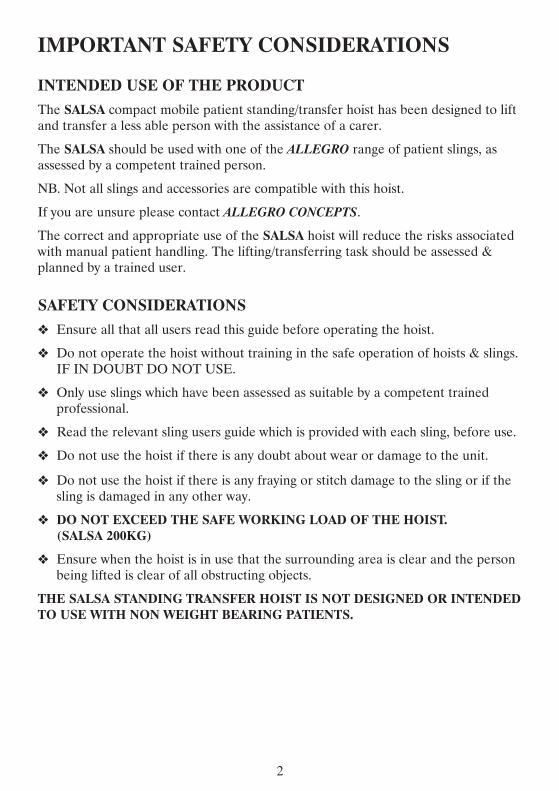
SALSA SPECIFICATIONS
11
GK002LWS
1050mm
655mm
585mm
1035mm
ELECTRIC
125mm
825mm
1670mm
482KG
1200mm
REMOVABLE
BASE LENGTH
EXTERNAL BASE WIDTH
INTERNAL BASE WIDTH CLOSED
INTERNAL BASE WIDTH OPEN
BASE WIDTH ADJ
UNDER BED CLEARANCE
MIN HEIGHT OF LIFT ARM
MAX HEIGHT OF LIFT ARM
MACHINE WEIGHT
MINIMUM STORAGE HEIGHT
FOOTPLATE
IMPORTANT SAFETY CONSIDERATIONS
INTENDED USE OF THE PRODUCT
The SALSA compact mobile patient standingtransfer hoist has been designed to lift and transfer a less able person with the assistance of a carer
The SALSA should be used with one of the ALLEGRO range of patient slings as assessed by a competent trained person
NB Not all slings and accessories are compatible with this hoist
If you are unsure please contact ALLEGRO CONCEPTS
The correct and appropriate use of the SALSA hoist will reduce the risks associated with manual patient handling The liftingtransferring task should be assessed amp planned by a trained user
SAFETY CONSIDERATIONS
Ensure all that all users read this guide before operating the hoist
Do not operate the hoist without training in the safe operation of hoists amp slings IF IN DOUBT DO NOT USE
Only use slings which have been assessed as suitable by a competent trained professional
Read the relevant sling users guide which is provided with each sling before use
Do not use the hoist if there is any doubt about wear or damage to the unit
Do not use the hoist if there is any fraying or stitch damage to the sling or if the sling is damaged in any other way
DO NOT EXCEED THE SAFE WORKING LOAD OF THE HOIST (SALSA 200KG)
Ensure when the hoist is in use that the surrounding area is clear and the person being lifted is clear of all obstructing objects
THE SALSA STANDING TRANSFER HOIST IS NOT DESIGNED OR INTENDED TO USE WITH NON WEIGHT BEARING PATIENTS
2
TROUBLE SHOOTINGWARNING TROUBLE SHOOTING SHOULD ONLY BE CARRIED OUT BY
ALLEGRO CONCEPTS AUTHORISED PERSONNEL FAMILIAR WITHBOTH USE ELECTRICAL AND MECHANICAL FEATURES OF PATIENT
LIFTING HOISTS
The following is a guideline only to general trouble shooting
Before carrying out any trouble shooting ensure that
Red emergency stop button is released
Maintenance procedures checked amp followed
All cable connections are secure
Battery is fully charged
10
POSSIBLE FAULT
Warning buzzer soundswithin control box
Flat battery packFaulty battery pack
Recharge batteryReplace battery
Battery charger power indicatorLED does not light up
No mains connectionInternal fuse blown
Battery chargers is defective
Plug into mainsReplace fuse
Repair replace charger
Actuator will not run and no relayclick is heard from control box
Control box is defectiveHandset defective Replace control box
Actuator will not run via handsetbut control box relays click
Actuator plugs not fully pushedin to control box
Actuator defectiveControl box defective
Push firmly into correct portReplace actuator or control
Actuator cannot lift full load orruns slow
Batteries not chargeddefectiveLoad too high for lifter
Actuator motor damaged
Chargereplace batteriesReplace actuator
No response from control boxno clicking of relays is heard
Emergency stop button engagedHoist battery completely flatBlown fuse in battery pack
Faulty control box
ReleaseCharge battery
Replacerepair control box
Actuator works in onedirection only
Handset defectiveControl box defective
Replace handsetRepairreplace control box
ACTION
PUSH
LIFT ARMS
ACTUATOR
KNEE PAD
BATTERY PACK
LEG
HANDLE
3
GENERAL MAINTENANCETo prolong the working life of the lifter and for trouble free operation it isrecommended that periodic inspections should be performed routinely and as oftenas necessary Periodic inspections should be performed by a person who is suitablyqualified and well acquainted with the design use and care of patient lifting hoists
If inspection reveals that the safety of the hoist is jeopardised in any way the hoistshould be IMMEDIATELY WITHDRAWN FROM SERVICE tagged as such andthe owner notified
MAINTENANCE GUIDE amp CHECK LISTbull General visual inspection of lifter
bull Check castors are tightly attached to legs
bull Check castors run amp swivel freely remove any hair amp fluff from axle
bull Check castor brakes operate efficiently
bull Over haul castors amp pack with grease
bull Inspect surfaces for scratches amp chips
bull Clean surfacers with a neutral detergent remove any adhesive tape with orangeor eucalyptus oil
bull Examine all moving parts and fasteners for wear and fatigue lubricate and oradjust as required
bull NB leg pivot bushes incorporate a Teflon coated pivot bush which requiresminimal lubrication
bull Check tightness of bolt in leg bushes
bull Check linkages are secure in leg adjuster ball joints
bull Check all electrical components for correct operation
bull Check battery charger operation
bull Remove dirt amp dust from actuator
bull Wipe actuator shaft with oiled rag (DO NOT use WD40 or equivalent)bull Check mast to boom pivot point remove bolts and lightly regrease bush and
retighten ensuring free movement at pivot
A MAJOR SERVICE SHOULD BE CARRIED OUT EVERY 12 MONTHSAS A MINIMUM REQUIREMENT
IMPORTANT An annual load test to the safe working load(swl) is required forcompliance with AS ISO 10535 minus 2002
9
ASSEMBLY INSTRUCTION S SALSA 200 All the ALLEGRO range of patient lifting and transfer hoists are fully assembled load tested and certified at the factory before being partially dismantled for packing and shipping Use the instructions below as a guide to assemble your SALSA standing hoist 1 Remove lifter components from protective packing and lay out on a smooth
surface to prevent damage to powder coating on lifter sub assemblies 2 Remove mastleg chassis weldment and slide one leg into receiver clevis Align
bolt holes push bolt through clevis and leg bush Thread nylock nut onto bolt on the under side of leg and tighten Ensure thread engages nylon locking ring of nut
3 Repeat process 2 for second leg 4 Attach leg adjuster tie rod ends to each leg and tighten each nylock nut 5 Attach lift actuator to lifting arm assembly by aligning actuator clevis with
actuator mount bracket Insert bolt and tighten nylock nut 6 Attach push handle assembly with hex bolts and washers supplied with handle
assembly 7 Attach Linak control box to mount plate with M5 hex bolt then attach clip on
battery pack 8 Plug the lift actuator cable into port 1 and the leg adjust cable into port 2 of the
control box Both ports are located on the underside of the control box (diagram 1)
9 Ensure both plugs are pushed in firmly into their respective sockets
Diagram 1 10 Locate handset and push into handset socket ensuring alignment of tongue of
plug with keyway of socket Push home firmly A smear of Vaseline on the O ring may assist if plug is tight Check operation of the SALSA via handset ensuring that the RED EMERGENCY STOP BUTTON ON THE CONTROL BOX IS RELEASED Turn the knob ndash turn clockwise to release
4
LIFTING PROCEDURESbull Carer should be fully conversant and trained in the use of lifter and sling This
will decrease patient apprehension and increase their coshyoperation and overallsafety of the lifting process
bull Where possible always pull the lifter for maximum safety and comfort
bull Move the hoist slowly to avoid patient swing whilst standing
bull The hoist should not be used on ramps with incline greater than 5 deg
bull Never leave a patient in a sling unattended
bull Ensure brakes of the chair bed trolley that the patient is being lifted from arelocked
bull The braking castors on the lifter should be off This allows the lifter to create itsown centre of gravity (CG) over the weight of the patient NB This action mayresult in the lifter moving slightly during the initial phase of the lift
GENERAL LIFTING PROCEDUREThe information supplied below is not intended to be construed as a training
manual but as a general guide to lifting procedure only
bull The SALSA hoist utilises a special type of padded sling designed to fit around thepatients lower back It utilises a restraint belt to help prevent the sling fromslipping and riding up the patients back the restraint belt is adjustable and fastenswith either a buckle or a velcro flap around the chest area
bull Key hole buckles on the sling clip onto the studs located on both lift arms of thehoist
bull For detailed sling fitting instructions refer to COMFORT STANDING SLINGUSER MANUAL
bull NB THIS SLING SHOULD ONLY BE USED WITH THE SALSA HOISTAND MAY NOT BE COMPATIBLE WITH OTHER PATIENT HOISTS
bull Manoeuvre the hoist around the patient adjusting the legs to fit around chairwheel chair etc If lifting from a bed ensure under bed clearance is sufficient tomanoeuvre legs under the bed
bull Lower the SALSA lift arms using the handset buttons until sling keyhole bucklescan reach and easily engage the studs on the lift arms to prevent possible injuryensure the lift arms do not come in contact with patients face or body
bull Place keyhole buckles onto the correct stud on each lift arm and pull firmly toengae and lock A slight resistance should be felt as the buckle moves to the lockposition
bull Use the handset to raise the hoist boom enough to take up the patients weight Atthis point stop the lift Check all sling attachments are secure and that the sling ispositioned correctly Check patient comfort Lower and realign sling if necessary
8
HOIST OPERATION AND CHARGING HANDSET
The handset activates the lift actuator by the use of two low pressure buttons protected by a strong plastic cover These are symbolised by arrows (diagram) The arrows indicate the direction of travel to raise or lower the hoist jib When either button is released the jib will remain in position
Some versions of ALLEGRO hoists incorporate an actuator driven leg opening adjustment On these hoists two extra buttons will be seen on the handset with arrows and symbolised legs indicating the direction of travel This function allows an unrestricted range of leg adjustment
The handset is also fitted with a battery indicator light This will flash when the batteries reach a maximum discharge of 18 volts NB the light will only flash when the hoist is under load
The connection for the handset is located on the underside of the control box (diagram 1)
HANDSET ACTUATOR RELEASE
LEG ADJUST
ACTUATOR
The SALSA 200 mobile patient STANDINGTRANSFER hoist uses a LINAK single speed actuator with an emergency controlled lowering release handle( red lift up tab located at base of actuator shaft) This allows the patient to be lowered in the event of a fault in the hoist or deep discharged batteries
5
CHARGING DOs amp DONrsquoTs
DODo charge the battery whenever possible This will extend the battery life A largenumber of cycles can be obtained from operating on the batteries but batterylifetime is reduced with frequent discharging
Do inspect all cables particularly the mains power cable on the charger for anydamage replace where necessary
Do stow the handset and if fitted with charger the mains power cable whentransporting the hoist
Do clean the actuators control box charger battery and handset at regularintervals to remove dust and dirt
DONrsquoTDonrsquot allow the batteries to fully discharge before connecting to chargerThebatteries are a lead acid gel type that can be trickle charged continuously andhave a high current discharge capacity The batteries are not the nickel cadmiumtype and must not be periodically fully discharged Battery life is greatly reducedby deep or complete discharging of the batteries Longer lifetime is obtained bymaintaining fully charged batteries
7
CHARGING The SALSA is suppled with a LINAK external wall mount charger This is activated by plugging the 3 pin plug into a standard 240Vac outlet
To recharge the battery pack perform the following steps
bull Release battery pack from control box by pulling the handle on the pack towards youUse both hands to support the battery pack when removing or replacing it
bull Clip the battery pack onto the charging unit ensuring it is seated properly on the charger base
bull Charger will automatically activate charging sequence
CHARGING INDICATOR LIGHTS
GREEN mains power on light will be illuminated when connected to 240 v power supply
ORANGE LIGHT illuminated indicates battery currently charging
ORANGE LIGHT will extinguish when battery pack is fully charged
LINAK CHARGER UNIT
240V INPUT SOCKET
6
CHARGINGThe SALSA is suppled with a LINAK external wall mount charger This isactivated by plugging the 3 pin plug into a standard 240Vac outlet
To recharge the battery pack perform the following steps
bull Release battery pack from control box by pulling the handle on the pack towardsyouUse both hands to support the battery pack when removing or replacing it
bull Clip the battery pack onto the charging unit ensuring it is seated properly on thecharger base
bull Charger will automatically activate charging sequence
CHARGING INDICATOR LIGHTSGREEN mains power on light will be illuminated when connected to 240 v powersupply
ORANGE LIGHT illuminated indicates battery currently charging
ORANGE LIGHT will extinguish when battery pack is fully charged
LINAK CHARGER UNIT
240VINPUT SOCKET
6
CHARGING DOs amp DONrsquoTs
DO
Do charge the battery whenever possible This will extend the battery life A large number of cycles can be obtained from operating on the batteries but battery lifetime is reduced with frequent discharging
Do inspect all cables particularly the mains power cable on the charger for any damage replace where necessary
Do stow the handset and if fitted with charger the mains power cable when transporting the hoist
Do clean the actuators control box charger battery and handset at regular intervals to remove dust and dirt
DONrsquoT
Donrsquot allow the batteries to fully discharge before connecting to chargerThe batteries are a lead acid gel type that can be trickle charged continuously and have a high current discharge capacity The batteries are not the nickel cadmium type and must not be periodically fully discharged Battery life is greatly reduced by deep or complete discharging of the batteries Longer lifetime is obtained by maintaining fully charged batteries
7
HOIST OPERATION AND CHARGINGHANDSET
The handset activates the lift actuator by the use of two low pressure buttonsprotected by a strong plastic cover These are symbolised by arrows (diagram)The arrows indicate the direction of travel to raise or lower the hoist jib Wheneither button is released the jib will remain in position
Some versions of ALLEGRO hoists incorporate an actuator driven leg openingadjustment On these hoists two extra buttons will be seen on the handset witharrows and symbolised legs indicating the direction of travel This function allowsan unrestricted range of leg adjustment
The handset is also fitted with a battery indicator light This will flash when thebatteries reach a maximum discharge of 18 volts NB the light will only flashwhen the hoist is under load
The connection for the handset is located on the underside of the control box(diagram 1)
ACTUATORThe SALSA 200 mobile patient STANDINGTRANSFER hoist uses a LINAKsingle speed actuator with an emergency controlled lowering release handle( red liftup tab located at base of actuator shaft) This allows the patient to be lowered in theevent of a fault in the hoist or deep discharged batteries
HANDSET ACTUATOR RELEASE
LEG ADJUST
5
LIFTING PROCEDURES bull Carer should be fully conversant and trained in the use of lifter and sling This
will decrease patient apprehension and increase their coshyoperation and overall safety of the lifting process
bull Where possible always pull the lifter for maximum safety and comfort
bull Move the hoist slowly to avoid patient swing whilst standing
bull The hoist should not be used on ramps with incline greater than 5 deg
bull Never leave a patient in a sling unattended
bull Ensure brakes of the chair bed trolley that the patient is being lifted from are locked
bull The braking castors on the lifter should be off This allows the lifter to create its own centre of gravity (CG) over the weight of the patient NB This action may result in the lifter moving slightly during the initial phase of the lift
GENERAL LIFTING PROCEDURE
The information supplied below is not intended to be construed as a training manual but as a general guide to lifting procedure only
bull The SALSA hoist utilises a special type of padded sling designed to fit around the patients lower back It utilises a restraint belt to help prevent the sling from slipping and riding up the patients back the restraint belt is adjustable and fastens with either a buckle or a velcro flap around the chest area
bull Key hole buckles on the sling clip onto the studs located on both lift arms of the hoist
bull For detailed sling fitting instructions refer to COMFORT STANDING SLING USER MANUAL
bull NB THIS SLING SHOULD ONLY BE USED WITH THE SALSA HOIST AND MAY NOT BE COMPATIBLE WITH OTHER PATIENT HOISTS
bull Manoeuvre the hoist around the patient adjusting the legs to fit around chair wheel chair etc If lifting from a bed ensure under bed clearance is sufficient to manoeuvre legs under the bed
bull Lower the SALSA lift arms using the handset buttons until sling keyhole buckles can reach and easily engage the studs on the lift arms to prevent possible injury ensure the lift arms do not come in contact with patients face or body
bull Place keyhole buckles onto the correct stud on each lift arm and pull firmly to engae and lock A slight resistance should be felt as the buckle moves to the lock position
bull Use the handset to raise the hoist boom enough to take up the patients weight At this point stop the lift Check all sling attachments are secure and that the sling is positioned correctly Check patient comfort Lower and realign sling if necessary
8
4
ASSEMBLY INSTRUCTION SSALSA 200All the ALLEGRO range of patient lifting and transfer hoists are fully assembledload tested and certified at the factory before being partially dismantled for packingand shippingUse the instructions below as a guide to assemble your SALSA standing hoist1 Remove lifter components from protective packing and lay out on a smooth
surface to prevent damage to powder coating on lifter sub assemblies2 Remove mastleg chassis weldment and slide one leg into receiver clevis Align
bolt holes push bolt through clevis and leg bush Thread nylock nut onto bolton the under side of leg and tighten Ensure thread engages nylon locking ringof nut
3 Repeat process 2 for second leg4 Attach leg adjuster tie rod ends to each leg and tighten each nylock nut5 Attach lift actuator to lifting arm assembly by aligning actuator clevis with
actuator mount bracket Insert bolt and tighten nylock nut6 Attach push handle assembly with hex bolts and washers supplied with handle
assembly7 Attach Linak control box to mount plate with M5 hex bolt then attach clip on
battery pack8 Plug the lift actuator cable into port 1 and the leg adjust cable into port 2 of the
control box Both ports are located on the underside of the control box(diagram 1)
9 Ensure both plugs are pushed in firmly into their respective sockets
Diagram 110 Locate handset and push into handset socket ensuring alignment of tongue of
plug with keyway of socket Push home firmly A smear of Vaseline on the Oring may assist if plug is tight Check operation of the SALSA via handsetensuring that the RED EMERGENCY STOP BUTTON ON THE CONTROLBOX IS RELEASED Turn the knob ndash turn clockwise to release
GENERAL MAINTENANCE To prolong the working life of the lifter and for trouble free operation it is recommended that periodic inspections should be performed routinely and as often as necessary Periodic inspections should be performed by a person who is suitably qualified and well acquainted with the design use and care of patient lifting hoists
If inspection reveals that the safety of the hoist is jeopardised in any way the hoist should be IMMEDIATELY WITHDRAWN FROM SERVICE tagged as such and the owner notified
MAINTENANCE GUIDE amp CHECK LIST bull General visual inspection of lifter
bull Check castors are tightly attached to legs
bull Check castors run amp swivel freely remove any hair amp fluff from axle
bull Check castor brakes operate efficiently
bull Over haul castors amp pack with grease
bull Inspect surfaces for scratches amp chips
bull Clean surfacers with a neutral detergent remove any adhesive tape with orange or eucalyptus oil
bull Examine all moving parts and fasteners for wear and fatigue lubricate and or adjust as required
bull NB leg pivot bushes incorporate a Teflon coated pivot bush which requires minimal lubrication
bull Check tightness of bolt in leg bushes
bull Check linkages are secure in leg adjuster ball joints
bull Check all electrical components for correct operation
bull Check battery charger operation
bull Remove dirt amp dust from actuator
bull Wipe actuator shaft with oiled rag (DO NOT use WD40 or equivalent) bull Check mast to boom pivot point remove bolts and lightly regrease bush and
retighten ensuring free movement at pivot
A MAJOR SERVICE SHOULD BE CARRIED OUT EVERY 12 MONTHS AS A MINIMUM REQUIREMENT
IMPORTANT An annual load test to the safe working load(swl) is required for compliance with AS ISO 10535 minus 2002
9
3
PUSHHANDLE
LIFT ARMS
ACTUATOR
KNEE PAD
BATTERYPACK
LEG
TROUBLE SHOOTING
WARNING TROUBLE SHOOTING SHOULD ONLY BE CARRIED OUT BY ALLEGRO CONCEPTS AUTHORISED PERSONNEL FAMILIAR WITH
BOTH USE ELECTRICAL AND MECHANICAL FEATURES OF PATIENT LIFTING HOISTS
The following is a guideline only to general trouble shooting
Before carrying out any trouble shooting ensure that
Red emergency stop button is released
Maintenance procedures checked amp followed
All cable connections are secure
Battery is fully charged
POSSIBLE FAULT ACTION
Warning buzzer sounds within control box
Flat battery pack Faulty battery pack
Recharge battery Replace battery
Battery charger power indicator LED does not light up
No mains connection Internal fuse blown
Battery chargers is defective
Plug into mains Replace fuse
Repair replace charger
Actuator will not run and no relay click is heard from control box
Control box is defective Handset defective Replace control box
Actuator will not run via handset but control box relays click
Actuator plugs not fully pushed in to control box
Actuator defective Control box defective
Push firmly into correct port Replace actuator or control
Actuator cannot lift full load or runs slow
Batteries not chargeddefective Load too high for lifter
Actuator motor damaged
Chargereplace batteries Replace actuator
No response from control box no clicking of relays is heard
Emergency stop button engaged Hoist battery completely flat Blown fuse in battery pack
Faulty control box
Release Charge battery
Replacerepair control box
Actuator works in one direction only
Handset defective Control box defective
Replace handset Repairreplace control box
10
IMPORTANT SAFETY CONSIDERATIONS
INTENDED USE OF THE PRODUCTThe SALSA compact mobile patient standingtransfer hoist has been designed to liftand transfer a less able person with the assistance of a carer
The SALSA should be used with one of the ALLEGRO range of patient slings asassessed by a competent trained person
NB Not all slings and accessories are compatible with this hoist
If you are unsure please contact ALLEGRO CONCEPTS
The correct and appropriate use of the SALSA hoist will reduce the risks associatedwith manual patient handling The liftingtransferring task should be assessed ampplanned by a trained user
SAFETY CONSIDERATIONSEnsure all that all users read this guide before operating the hoist
Do not operate the hoist without training in the safe operation of hoists amp slingsIF IN DOUBT DO NOT USE
Only use slings which have been assessed as suitable by a competent trainedprofessional
Read the relevant sling users guide which is provided with each sling before use
Do not use the hoist if there is any doubt about wear or damage to the unit
Do not use the hoist if there is any fraying or stitch damage to the sling or if thesling is damaged in any other way
DO NOT EXCEED THE SAFE WORKING LOAD OF THE HOIST(SALSA 200KG)
Ensure when the hoist is in use that the surrounding area is clear and the personbeing lifted is clear of all obstructing objects
THE SALSA STANDING TRANSFER HOIST IS NOT DESIGNED OR INTENDEDTO USE WITH NON WEIGHT BEARING PATIENTS
2
SALSA SPECIFICATIONS
SWL 200KG
BASE LENGTH 1050mm
EXTERNAL BASE WIDTH 655mm
INTERNAL BASE WIDTH CLOSED 585mm
INTERNAL BASE WIDTH OPEN 1035mm
BASE WIDTH ADJ ELECTRIC
UNDER BED CLEARANCE 125mm
MIN HEIGHT OF LIFT ARM 825mm
MAX HEIGHT OF LIFT ARM 1670mm
MACHINE WEIGHT 482KG
MINIMUM STORAGE HEIGHT 1200mm
FOOTPLATE REMOVABLE
11
SALSAOVERVIEWThe SALSA mobile standing hoist is designed to assist the less than able persontransfer from a seated position to a supported standing position
The SALSA whilst compact and manoeuvrable has a safe working load (SWL) of200KG This lifter is suited to both home or institutional use
The SALSA is an electric operated hoist with ergonomic features designed with thepatient and carer in mind
An ALLEGRO standing sling specifically designed for the SALSA is available Thissling provides maximum support and comfort for the patient
1
The Allegro Concepts range of patient lifting equipment including lifters slings and accessories has been designed and tested in house to comply with
AS ISO 10535 ndash 2002
Hoists for the transfer of disabled persons ndash Requirements and test methods
WARRANTY ALLEGRO CONCEPTS PTY LTD warrants its products to be free from defects in materials and workmanship under normal use and service and will within the period stated below from the date of purchase repair or replace without cost to the original customer any part assembly or portion thereof which shall be returned to ALLEGRO CONCEPTS and from OUR inspection shows to be defective
Patient lifter including electronics 2 years
Accessories on lifter 2 years
Patient slings 1 year
Weighing devices 1 year
Batteries 3 months
ALLEGRO CONCEPTS PTY LTD cannot be held responsible for any personal injury damage to the hoist or damage to property as a result of the improper or unsafe use of the product
No warranty claim shall apply where the product or any part thereof has been modified varied altered or damaged either accidentally or through improper or negligent use
No warranty claim shall apply where the hoist is repaired or serviced by any persons not accredited by the authorised distributor
Warranty does not extend to items or components which may require replacement due to normal wear and tear ( eg castors mouldings and paint work ) for which ALLEGRO CONCEPTS nor its distributors can be held responsible
BATTERIES
Batteries carry a limited warranty from the original manufacturer which is subject to a stringent wear and tear clause Any battery faults due to defect in original manufacture will normally become apparent within the first two months of use
Any gradual deterioration in performance after this period is normally associated with fair wear and tear misuse and accidental damage and as such is not covered by the manufacturers warranty
12
CONTENTS
SALSA LIFT 200 OVERVIEW 1
IMPORTANT SAFETY CONSIDERATIONS 2
SALSA LIFT 200 ASSEMBLY INSTRUCTIONS 3
HOIST OPERATION AND CHARGING 5
LIFTING PROCEDURES 8
MAINTENANCE 9
TROUBLE SHOOTING 10
SPECIFICATIONS 11
WARRANTY 12
LOG BOOK 13
LOG BOOK
SERVICE TYPE CONDITION REPORT
DATE
INSPECTED BY
SIGNATURE ACTION TAKEN
SERVICE TYPE CONDITION REPORT
DATE
INSPECTED BY
SIGNATURE ACTION TAKEN
13
SALSAMOBILE STANDING TRANSFER HOIST
IMPORTANTDO NOT USE THE SALSA STANDING TRANSFER
LIFTER WITHOUT HAVING FIRST READ THISMANUAL
DISTRIBUTED BY
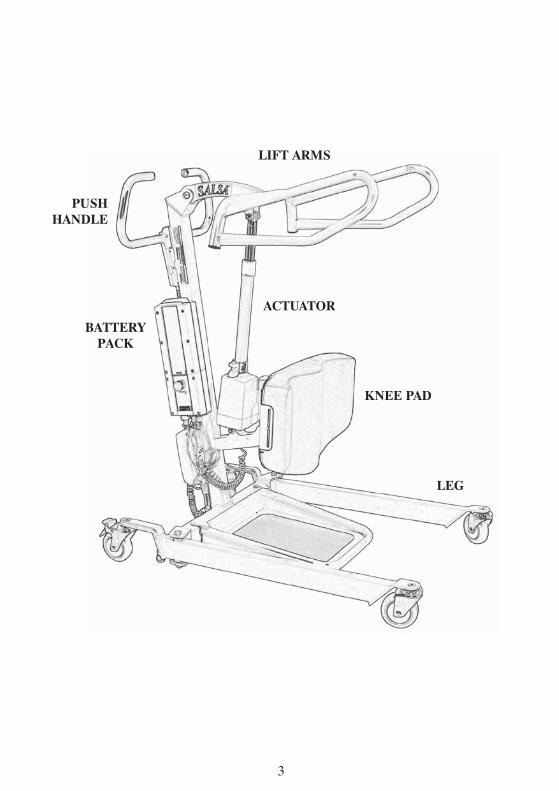
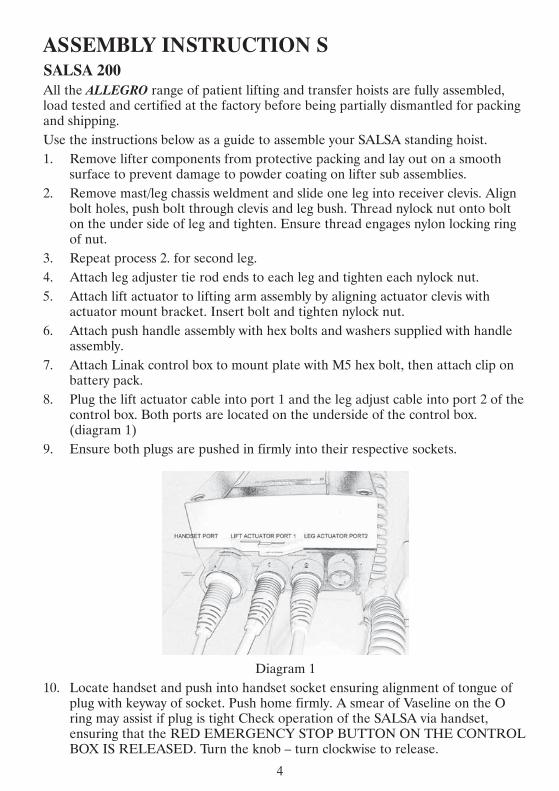
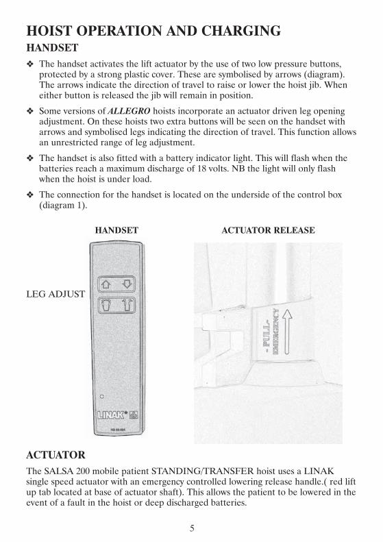

CHARGING DOs amp DONrsquoTs
DODo charge the battery whenever possible This will extend the battery life A largenumber of cycles can be obtained from operating on the batteries but batterylifetime is reduced with frequent discharging
Do inspect all cables particularly the mains power cable on the charger for anydamage replace where necessary
Do stow the handset and if fitted with charger the mains power cable whentransporting the hoist
Do clean the actuators control box charger battery and handset at regularintervals to remove dust and dirt
DONrsquoTDonrsquot allow the batteries to fully discharge before connecting to chargerThebatteries are a lead acid gel type that can be trickle charged continuously andhave a high current discharge capacity The batteries are not the nickel cadmiumtype and must not be periodically fully discharged Battery life is greatly reducedby deep or complete discharging of the batteries Longer lifetime is obtained bymaintaining fully charged batteries
7
CHARGING The SALSA is suppled with a LINAK external wall mount charger This is activated by plugging the 3 pin plug into a standard 240Vac outlet
To recharge the battery pack perform the following steps
bull Release battery pack from control box by pulling the handle on the pack towards youUse both hands to support the battery pack when removing or replacing it
bull Clip the battery pack onto the charging unit ensuring it is seated properly on the charger base
bull Charger will automatically activate charging sequence
CHARGING INDICATOR LIGHTS
GREEN mains power on light will be illuminated when connected to 240 v power supply
ORANGE LIGHT illuminated indicates battery currently charging
ORANGE LIGHT will extinguish when battery pack is fully charged
LINAK CHARGER UNIT
240V INPUT SOCKET
6
CHARGINGThe SALSA is suppled with a LINAK external wall mount charger This isactivated by plugging the 3 pin plug into a standard 240Vac outlet
To recharge the battery pack perform the following steps
bull Release battery pack from control box by pulling the handle on the pack towardsyouUse both hands to support the battery pack when removing or replacing it
bull Clip the battery pack onto the charging unit ensuring it is seated properly on thecharger base
bull Charger will automatically activate charging sequence
CHARGING INDICATOR LIGHTSGREEN mains power on light will be illuminated when connected to 240 v powersupply
ORANGE LIGHT illuminated indicates battery currently charging
ORANGE LIGHT will extinguish when battery pack is fully charged
LINAK CHARGER UNIT
240VINPUT SOCKET
6
CHARGING DOs amp DONrsquoTs
DO
Do charge the battery whenever possible This will extend the battery life A large number of cycles can be obtained from operating on the batteries but battery lifetime is reduced with frequent discharging
Do inspect all cables particularly the mains power cable on the charger for any damage replace where necessary
Do stow the handset and if fitted with charger the mains power cable when transporting the hoist
Do clean the actuators control box charger battery and handset at regular intervals to remove dust and dirt
DONrsquoT
Donrsquot allow the batteries to fully discharge before connecting to chargerThe batteries are a lead acid gel type that can be trickle charged continuously and have a high current discharge capacity The batteries are not the nickel cadmium type and must not be periodically fully discharged Battery life is greatly reduced by deep or complete discharging of the batteries Longer lifetime is obtained by maintaining fully charged batteries
7
HOIST OPERATION AND CHARGINGHANDSET
The handset activates the lift actuator by the use of two low pressure buttonsprotected by a strong plastic cover These are symbolised by arrows (diagram)The arrows indicate the direction of travel to raise or lower the hoist jib Wheneither button is released the jib will remain in position
Some versions of ALLEGRO hoists incorporate an actuator driven leg openingadjustment On these hoists two extra buttons will be seen on the handset witharrows and symbolised legs indicating the direction of travel This function allowsan unrestricted range of leg adjustment
The handset is also fitted with a battery indicator light This will flash when thebatteries reach a maximum discharge of 18 volts NB the light will only flashwhen the hoist is under load
The connection for the handset is located on the underside of the control box(diagram 1)
ACTUATORThe SALSA 200 mobile patient STANDINGTRANSFER hoist uses a LINAKsingle speed actuator with an emergency controlled lowering release handle( red liftup tab located at base of actuator shaft) This allows the patient to be lowered in theevent of a fault in the hoist or deep discharged batteries
HANDSET ACTUATOR RELEASE
LEG ADJUST
5
LIFTING PROCEDURES bull Carer should be fully conversant and trained in the use of lifter and sling This
will decrease patient apprehension and increase their coshyoperation and overall safety of the lifting process
bull Where possible always pull the lifter for maximum safety and comfort
bull Move the hoist slowly to avoid patient swing whilst standing
bull The hoist should not be used on ramps with incline greater than 5 deg
bull Never leave a patient in a sling unattended
bull Ensure brakes of the chair bed trolley that the patient is being lifted from are locked
bull The braking castors on the lifter should be off This allows the lifter to create its own centre of gravity (CG) over the weight of the patient NB This action may result in the lifter moving slightly during the initial phase of the lift
GENERAL LIFTING PROCEDURE
The information supplied below is not intended to be construed as a training manual but as a general guide to lifting procedure only
bull The SALSA hoist utilises a special type of padded sling designed to fit around the patients lower back It utilises a restraint belt to help prevent the sling from slipping and riding up the patients back the restraint belt is adjustable and fastens with either a buckle or a velcro flap around the chest area
bull Key hole buckles on the sling clip onto the studs located on both lift arms of the hoist
bull For detailed sling fitting instructions refer to COMFORT STANDING SLING USER MANUAL
bull NB THIS SLING SHOULD ONLY BE USED WITH THE SALSA HOIST AND MAY NOT BE COMPATIBLE WITH OTHER PATIENT HOISTS
bull Manoeuvre the hoist around the patient adjusting the legs to fit around chair wheel chair etc If lifting from a bed ensure under bed clearance is sufficient to manoeuvre legs under the bed
bull Lower the SALSA lift arms using the handset buttons until sling keyhole buckles can reach and easily engage the studs on the lift arms to prevent possible injury ensure the lift arms do not come in contact with patients face or body
bull Place keyhole buckles onto the correct stud on each lift arm and pull firmly to engae and lock A slight resistance should be felt as the buckle moves to the lock position
bull Use the handset to raise the hoist boom enough to take up the patients weight At this point stop the lift Check all sling attachments are secure and that the sling is positioned correctly Check patient comfort Lower and realign sling if necessary
8
4
ASSEMBLY INSTRUCTION SSALSA 200All the ALLEGRO range of patient lifting and transfer hoists are fully assembledload tested and certified at the factory before being partially dismantled for packingand shippingUse the instructions below as a guide to assemble your SALSA standing hoist1 Remove lifter components from protective packing and lay out on a smooth
surface to prevent damage to powder coating on lifter sub assemblies2 Remove mastleg chassis weldment and slide one leg into receiver clevis Align
bolt holes push bolt through clevis and leg bush Thread nylock nut onto bolton the under side of leg and tighten Ensure thread engages nylon locking ringof nut
3 Repeat process 2 for second leg4 Attach leg adjuster tie rod ends to each leg and tighten each nylock nut5 Attach lift actuator to lifting arm assembly by aligning actuator clevis with
actuator mount bracket Insert bolt and tighten nylock nut6 Attach push handle assembly with hex bolts and washers supplied with handle
assembly7 Attach Linak control box to mount plate with M5 hex bolt then attach clip on
battery pack8 Plug the lift actuator cable into port 1 and the leg adjust cable into port 2 of the
control box Both ports are located on the underside of the control box(diagram 1)
9 Ensure both plugs are pushed in firmly into their respective sockets
Diagram 110 Locate handset and push into handset socket ensuring alignment of tongue of
plug with keyway of socket Push home firmly A smear of Vaseline on the Oring may assist if plug is tight Check operation of the SALSA via handsetensuring that the RED EMERGENCY STOP BUTTON ON THE CONTROLBOX IS RELEASED Turn the knob ndash turn clockwise to release
GENERAL MAINTENANCE To prolong the working life of the lifter and for trouble free operation it is recommended that periodic inspections should be performed routinely and as often as necessary Periodic inspections should be performed by a person who is suitably qualified and well acquainted with the design use and care of patient lifting hoists
If inspection reveals that the safety of the hoist is jeopardised in any way the hoist should be IMMEDIATELY WITHDRAWN FROM SERVICE tagged as such and the owner notified
MAINTENANCE GUIDE amp CHECK LIST bull General visual inspection of lifter
bull Check castors are tightly attached to legs
bull Check castors run amp swivel freely remove any hair amp fluff from axle
bull Check castor brakes operate efficiently
bull Over haul castors amp pack with grease
bull Inspect surfaces for scratches amp chips
bull Clean surfacers with a neutral detergent remove any adhesive tape with orange or eucalyptus oil
bull Examine all moving parts and fasteners for wear and fatigue lubricate and or adjust as required
bull NB leg pivot bushes incorporate a Teflon coated pivot bush which requires minimal lubrication
bull Check tightness of bolt in leg bushes
bull Check linkages are secure in leg adjuster ball joints
bull Check all electrical components for correct operation
bull Check battery charger operation
bull Remove dirt amp dust from actuator
bull Wipe actuator shaft with oiled rag (DO NOT use WD40 or equivalent) bull Check mast to boom pivot point remove bolts and lightly regrease bush and
retighten ensuring free movement at pivot
A MAJOR SERVICE SHOULD BE CARRIED OUT EVERY 12 MONTHS AS A MINIMUM REQUIREMENT
IMPORTANT An annual load test to the safe working load(swl) is required for compliance with AS ISO 10535 minus 2002
9
3
PUSHHANDLE
LIFT ARMS
ACTUATOR
KNEE PAD
BATTERYPACK
LEG
TROUBLE SHOOTING
WARNING TROUBLE SHOOTING SHOULD ONLY BE CARRIED OUT BY ALLEGRO CONCEPTS AUTHORISED PERSONNEL FAMILIAR WITH
BOTH USE ELECTRICAL AND MECHANICAL FEATURES OF PATIENT LIFTING HOISTS
The following is a guideline only to general trouble shooting
Before carrying out any trouble shooting ensure that
Red emergency stop button is released
Maintenance procedures checked amp followed
All cable connections are secure
Battery is fully charged
POSSIBLE FAULT ACTION
Warning buzzer sounds within control box
Flat battery pack Faulty battery pack
Recharge battery Replace battery
Battery charger power indicator LED does not light up
No mains connection Internal fuse blown
Battery chargers is defective
Plug into mains Replace fuse
Repair replace charger
Actuator will not run and no relay click is heard from control box
Control box is defective Handset defective Replace control box
Actuator will not run via handset but control box relays click
Actuator plugs not fully pushed in to control box
Actuator defective Control box defective
Push firmly into correct port Replace actuator or control
Actuator cannot lift full load or runs slow
Batteries not chargeddefective Load too high for lifter
Actuator motor damaged
Chargereplace batteries Replace actuator
No response from control box no clicking of relays is heard
Emergency stop button engaged Hoist battery completely flat Blown fuse in battery pack
Faulty control box
Release Charge battery
Replacerepair control box
Actuator works in one direction only
Handset defective Control box defective
Replace handset Repairreplace control box
10
IMPORTANT SAFETY CONSIDERATIONS
INTENDED USE OF THE PRODUCTThe SALSA compact mobile patient standingtransfer hoist has been designed to liftand transfer a less able person with the assistance of a carer
The SALSA should be used with one of the ALLEGRO range of patient slings asassessed by a competent trained person
NB Not all slings and accessories are compatible with this hoist
If you are unsure please contact ALLEGRO CONCEPTS
The correct and appropriate use of the SALSA hoist will reduce the risks associatedwith manual patient handling The liftingtransferring task should be assessed ampplanned by a trained user
SAFETY CONSIDERATIONSEnsure all that all users read this guide before operating the hoist
Do not operate the hoist without training in the safe operation of hoists amp slingsIF IN DOUBT DO NOT USE
Only use slings which have been assessed as suitable by a competent trainedprofessional
Read the relevant sling users guide which is provided with each sling before use
Do not use the hoist if there is any doubt about wear or damage to the unit
Do not use the hoist if there is any fraying or stitch damage to the sling or if thesling is damaged in any other way
DO NOT EXCEED THE SAFE WORKING LOAD OF THE HOIST(SALSA 200KG)
Ensure when the hoist is in use that the surrounding area is clear and the personbeing lifted is clear of all obstructing objects
THE SALSA STANDING TRANSFER HOIST IS NOT DESIGNED OR INTENDEDTO USE WITH NON WEIGHT BEARING PATIENTS
2
SALSA SPECIFICATIONS
SWL 200KG
BASE LENGTH 1050mm
EXTERNAL BASE WIDTH 655mm
INTERNAL BASE WIDTH CLOSED 585mm
INTERNAL BASE WIDTH OPEN 1035mm
BASE WIDTH ADJ ELECTRIC
UNDER BED CLEARANCE 125mm
MIN HEIGHT OF LIFT ARM 825mm
MAX HEIGHT OF LIFT ARM 1670mm
MACHINE WEIGHT 482KG
MINIMUM STORAGE HEIGHT 1200mm
FOOTPLATE REMOVABLE
11
SALSAOVERVIEWThe SALSA mobile standing hoist is designed to assist the less than able persontransfer from a seated position to a supported standing position
The SALSA whilst compact and manoeuvrable has a safe working load (SWL) of200KG This lifter is suited to both home or institutional use
The SALSA is an electric operated hoist with ergonomic features designed with thepatient and carer in mind
An ALLEGRO standing sling specifically designed for the SALSA is available Thissling provides maximum support and comfort for the patient
1
The Allegro Concepts range of patient lifting equipment including lifters slings and accessories has been designed and tested in house to comply with
AS ISO 10535 ndash 2002
Hoists for the transfer of disabled persons ndash Requirements and test methods
WARRANTY ALLEGRO CONCEPTS PTY LTD warrants its products to be free from defects in materials and workmanship under normal use and service and will within the period stated below from the date of purchase repair or replace without cost to the original customer any part assembly or portion thereof which shall be returned to ALLEGRO CONCEPTS and from OUR inspection shows to be defective
Patient lifter including electronics 2 years
Accessories on lifter 2 years
Patient slings 1 year
Weighing devices 1 year
Batteries 3 months
ALLEGRO CONCEPTS PTY LTD cannot be held responsible for any personal injury damage to the hoist or damage to property as a result of the improper or unsafe use of the product
No warranty claim shall apply where the product or any part thereof has been modified varied altered or damaged either accidentally or through improper or negligent use
No warranty claim shall apply where the hoist is repaired or serviced by any persons not accredited by the authorised distributor
Warranty does not extend to items or components which may require replacement due to normal wear and tear ( eg castors mouldings and paint work ) for which ALLEGRO CONCEPTS nor its distributors can be held responsible
BATTERIES
Batteries carry a limited warranty from the original manufacturer which is subject to a stringent wear and tear clause Any battery faults due to defect in original manufacture will normally become apparent within the first two months of use
Any gradual deterioration in performance after this period is normally associated with fair wear and tear misuse and accidental damage and as such is not covered by the manufacturers warranty
12
CONTENTS
SALSA LIFT 200 OVERVIEW 1
IMPORTANT SAFETY CONSIDERATIONS 2
SALSA LIFT 200 ASSEMBLY INSTRUCTIONS 3
HOIST OPERATION AND CHARGING 5
LIFTING PROCEDURES 8
MAINTENANCE 9
TROUBLE SHOOTING 10
SPECIFICATIONS 11
WARRANTY 12
LOG BOOK 13
LOG BOOK
SERVICE TYPE CONDITION REPORT
DATE
INSPECTED BY
SIGNATURE ACTION TAKEN
SERVICE TYPE CONDITION REPORT
DATE
INSPECTED BY
SIGNATURE ACTION TAKEN
13
SALSAMOBILE STANDING TRANSFER HOIST
IMPORTANTDO NOT USE THE SALSA STANDING TRANSFER
LIFTER WITHOUT HAVING FIRST READ THISMANUAL
DISTRIBUTED BY
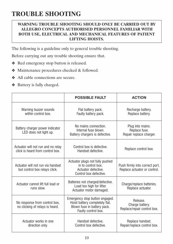

SALSAMOBILE STANDING TRANSFER HOIST
IMPORTANTDO NOT USE THE SALSA STANDING TRANSFER
LIFTER WITHOUT HAVING FIRST READ THISMANUAL
DISTRIBUTED BY
Recommended