ANGLE MEASUREMENTS
B.Ramamoorthy
Manufacturing Engg. Section
IIT,Madras 600036
ANGLE MEASUREMENTS
Sine bar
Autocollimator
Electronic Level
Profile Projector
Laser Interferometer
CMM etc
Tool maker’s microscope
Angle Gauges Spirit level
Protractors
Clinometer
Beam comparator

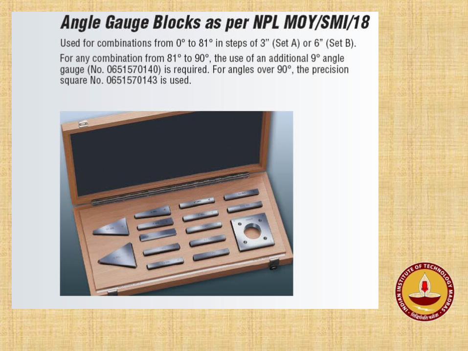
Angle Gauges
Available in sets
1, 3, 9, 27, 41- degrees
1, 3, 9, 27 - minutes
3, 9, 27 or 6, 12, 18 – seconds
plus a square block 13 gauges in Set 1
1, 3, 5, 15, 30, 45 - degrees
1, 3, 5, 20, 30 - minutes
1, 3, 5, 20, 30 - seconds plus a square block 17 gauges in Set 2
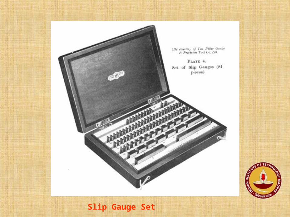
Slip Gauge Set


Wringing of Slip gauges

Clinging power of Slip Gauges

89
89
3.2
16
Typical size and shape of an angle Gauge
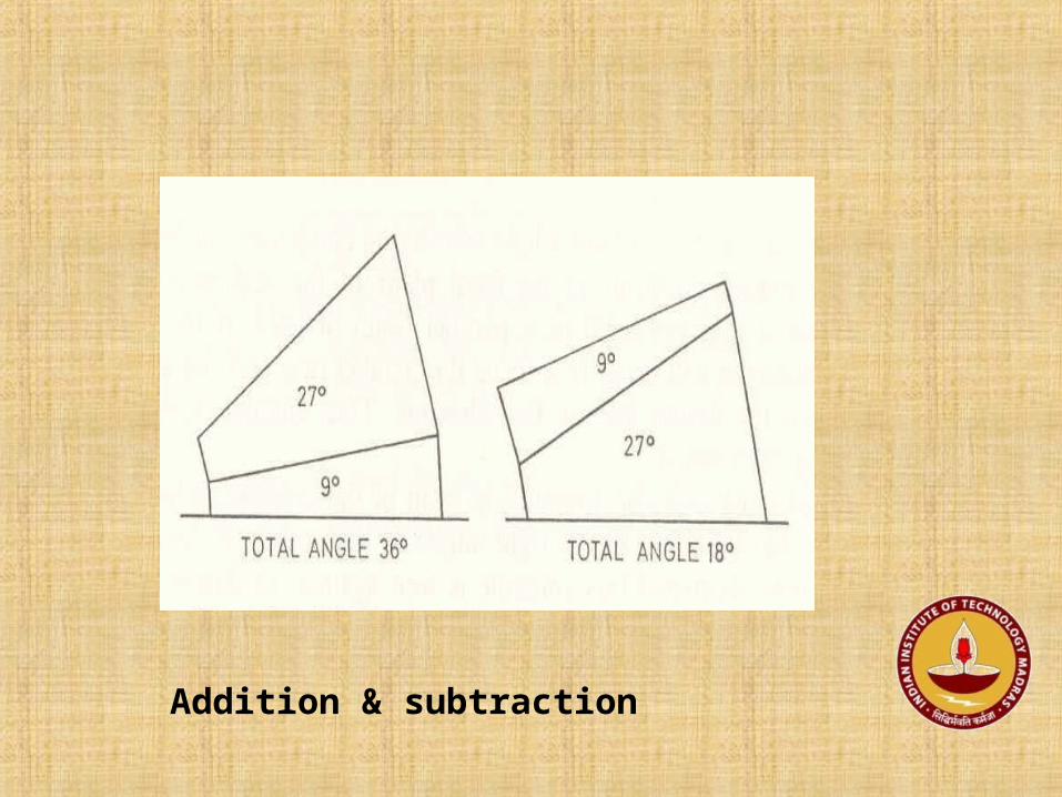
Addition & subtraction


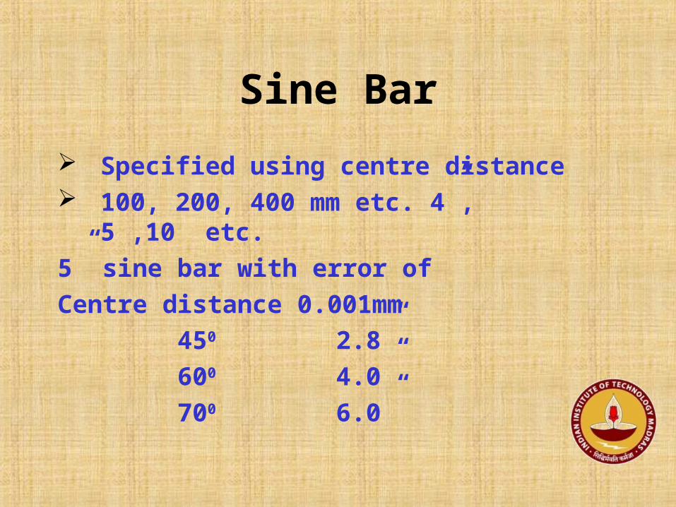
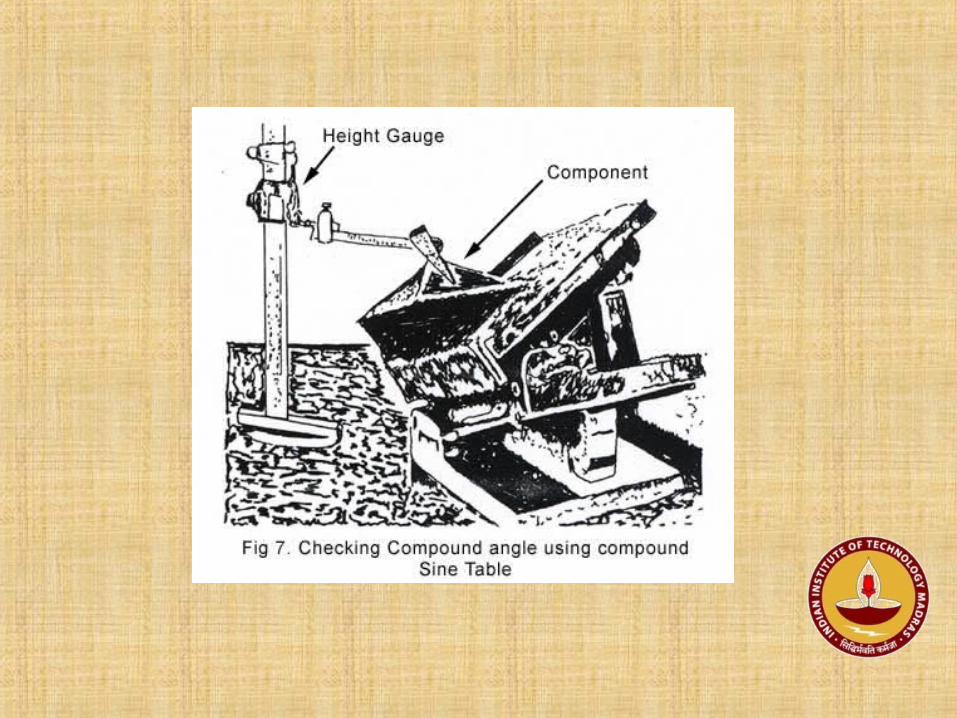
Sine Bar
Specified using centre distance 100, 200, 400 mm etc. 4”, 5”,10” etc.
5” sine bar with error of
Centre distance 0.001mm
450 2.8”
600 4.0”
700 6.0”


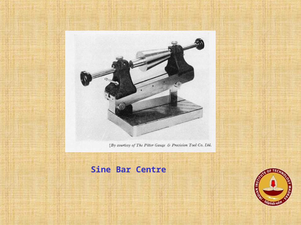
Sine Bar Centre


Gage
Block

Sine Bars - Block Type


Spirit level
To measure the angular divergencies
Simple and yet powerful
Sensitivity is defined as the
Displacement of bubble / Change in inclination in mm / sec
R = L / θ = 2. 5 mm / 10 secs
= 50 m app.

Spirit Level – Principle, (R = t / )

Sensitivity =Displacement Per scale division of bubble for a Change in
inclination ( mm / sec ) R = L / θ = 2. 5 mm / 10 secs = 50 m app.
θ
L
R

Block Levels


Principle of Auto Collimation

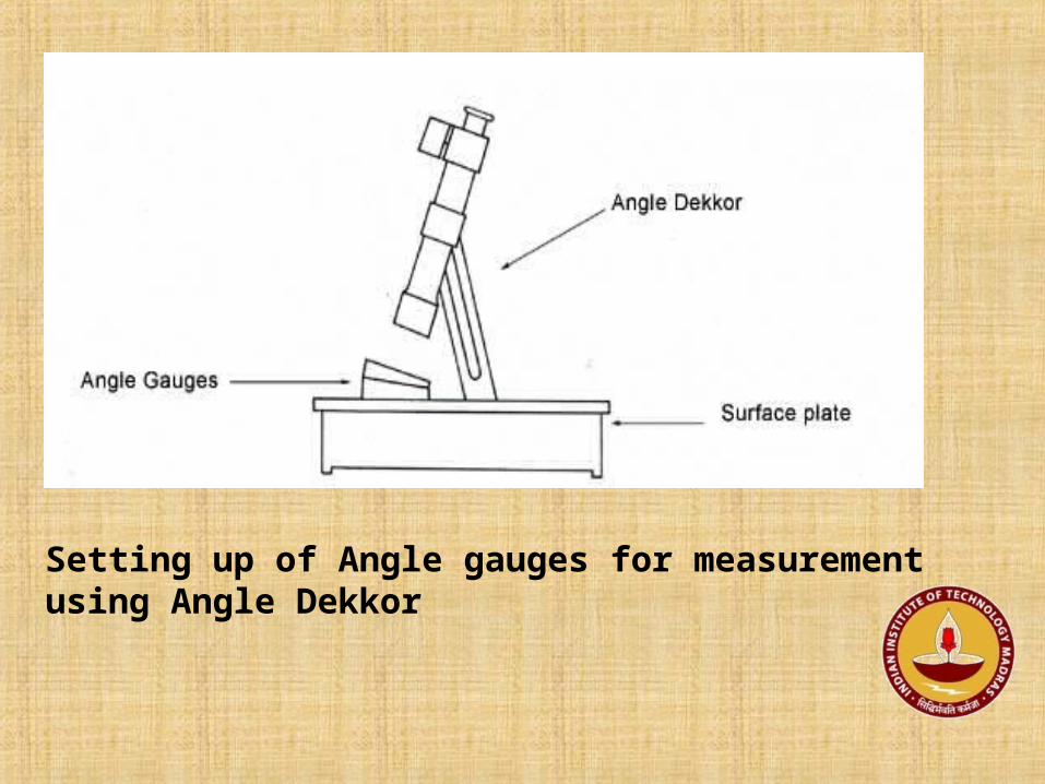
Setting up of Angle gauges for measurement using Angle Dekkor

Angle Dekkor – and Eyepiece view

Angle Dekkor – Eyepiece view

Optical diagram of a Micro optic Auto collimator
1 eyepiece
2,4 prisms
3 beamsplitter
5 crosswire
6 lamp
7,8 reflectors
9 objective
lens
10 plane of setting images
Minute’s scale knobSecond’s scale knob

1 optical flat
2 minute’s scale knob
3 Ocular
4 minute scale
5 Second’s scale
6 Cam
7 Pinion
8 Knob for tilting flat
9 Gear wheel
10 Pin
Measuring Ocular and its reticules
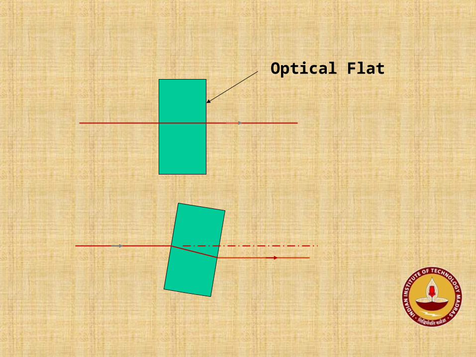
Optical Flat

Reticules (minutes and Seconds) and Reading of the Ocular


θ

AutoCollimator – eyepiece view


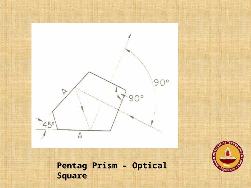
Pentag Prism – Optical Square

Prisms..

Polygons

Angle Gauges

Slip Gauge Set

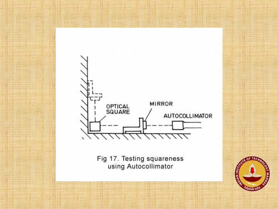

Auto Collimator- Squareness testing

Angle Dekkor – Checking right angle


Squareness Tester

Squareness checking – Dial gauge

Circular Table

Auto collimator-Calibration of a circular Table with a polygon

AC
Square Block
Circular Table


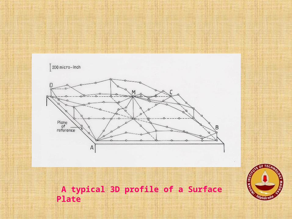
A typical 3D profile of a Surface Plate

Straightness Checking – AutoCollimator and reflector

Straightness Checking – AutoCollimator and reflector, Readings
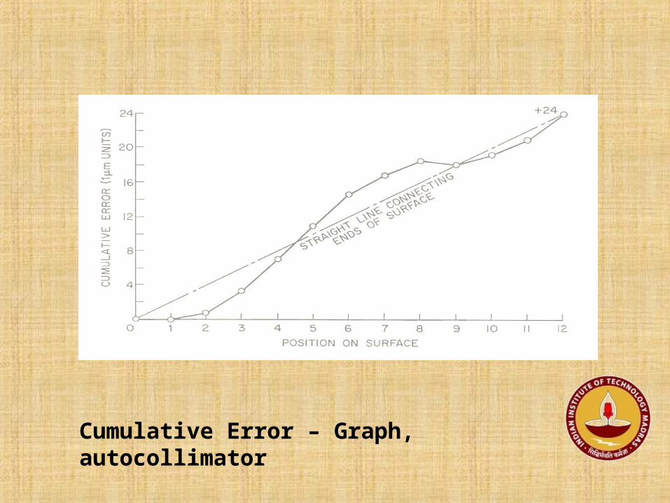
Cumulative Error – Graph, autocollimator

Cumulative and Actual Error Graphs – Autocollimator

Testing a machine tool and readings ,straightness plot

5 ”
4 ”
Straightness Evaluation – Autocollimator readings
Readings – 10 ’ 00 ’,10 ’10 ’’,9 ’55” ,10 ’15”,9 ’56”
Pitch distance – 100mm
10”
15”

5
108.0
10”
15”1.6
2.5
4.8
End points Zero Method
2.3
3.6
5.0
0
Straightness error = 3.6 +2.3µm
End Points Zero Line

10”
15”
Error = 5.0 µm
Crest points Method
Crest points line
5.0
10.012.5
7.5
2.50.0
10” = 5 µm

Error = 6.25µm
Valley points method
Valley points line -1
Valley points line -2
2.53.75
5.0
5.0
10.0
7.5
Error = 5.0 µm

Valley points line10”
15”
Crest points line
End points zero line
Straightness Evaluation - Methods


Profile Projector

Light rays from Lamp
Glass Table
Lens
Reflecting Mirror
Glass Screen
Profile Projector/Shadow Graph

Tool maker’s Microscope

Lamp
To Eye Piece
Lens
Tool Maker’s MicroscopeReflector
Glass Table


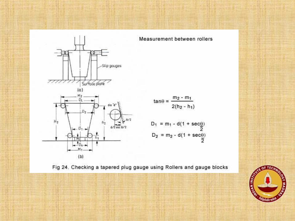

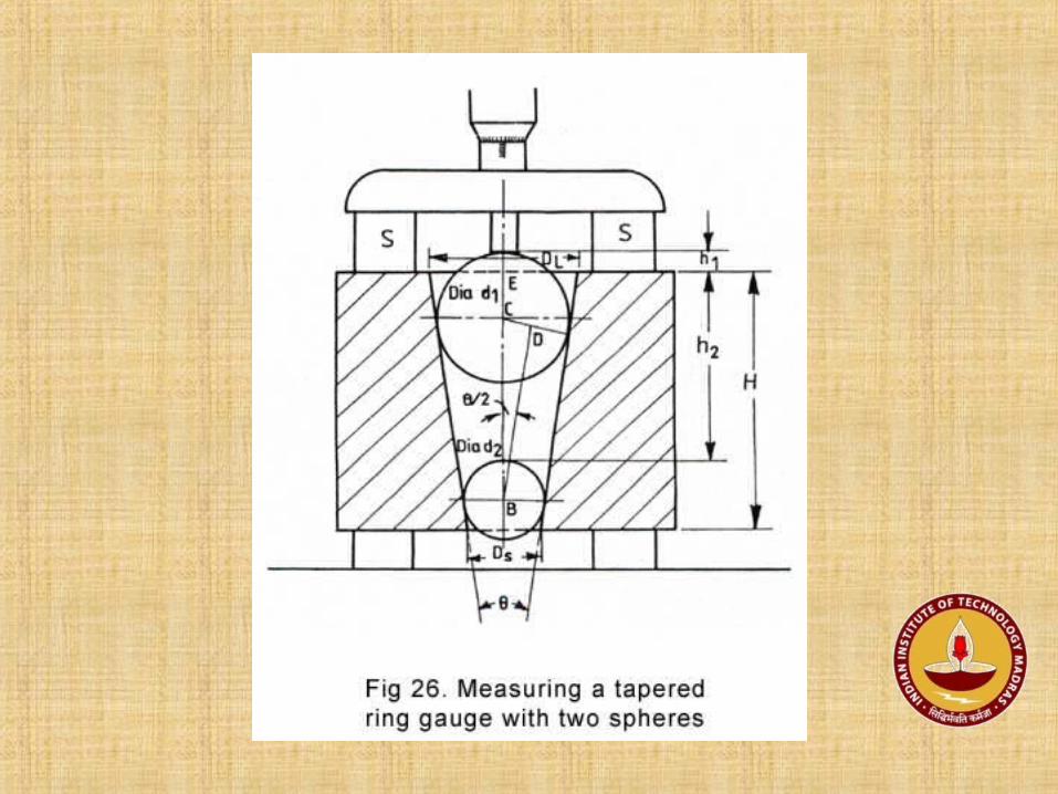
m1
d/2 Sec Ө / 2 Ө/2
Diameter “ d ”
Ө/2
D1


Talyvel with a stride base (to set horizontal lines)
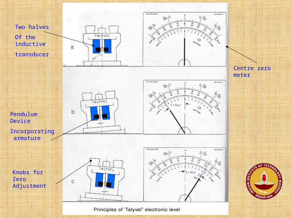
Two halves
Of the inductive
transducer
Centre zero meter
Pendulum Device
Incorporating armature
Knobs for Zero Adjustment

Talyvel with Meter unit (battery operated)
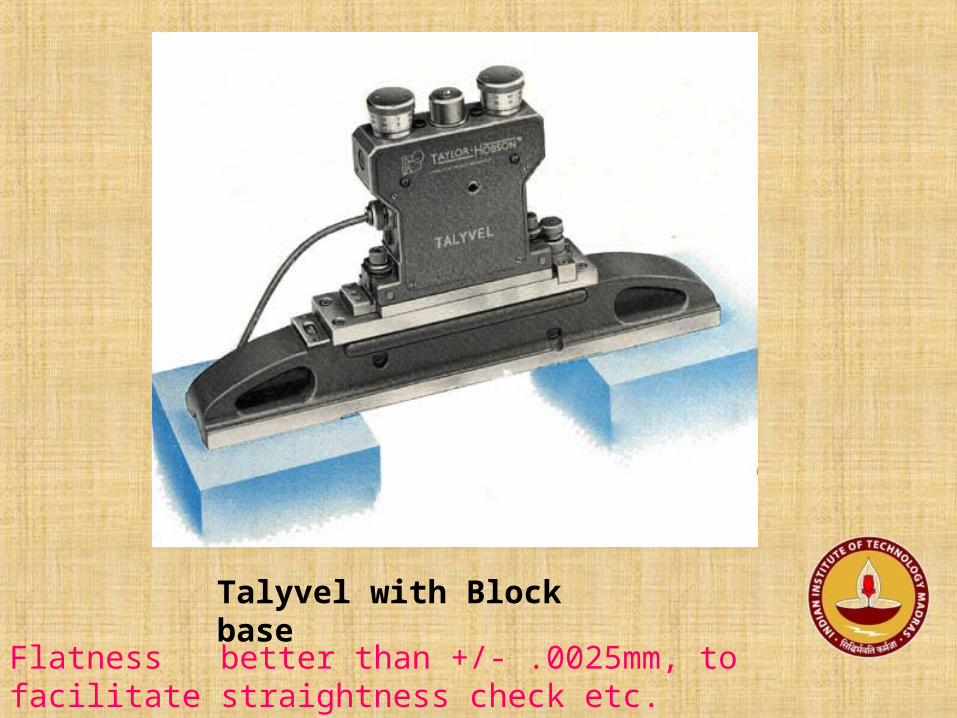
Talyvel with Block base
Flatness better than +/- .0025mm, to facilitate straightness check etc.

Rochdale’s Beam Comparator
Surface plate
Dial gauge
Beam comparator

Rochdale - Beam Comparator


Clinometer


Straightness Testing – Wedge Method
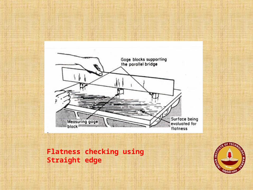
Flatness checking using Straight edge

Flatness Evaluation

Reading Assignments
1)Manufacture of surface Plates – reason?
2) Large radius Grinding – Spirit Level
3) Parallelism of Micrometer faces – how to check using AC?
Recommended