BRAINPowerSupplyDesktop PC Power Supply
Nonstop (Uninterruptible / No Power-interruption) Power Supply
31 mNSP3-450P-S20 series Specification, design, and prices in the catalog are subject to change without prior notice. Do not copy. Copyright 2013 Nipron Co., Ltd.
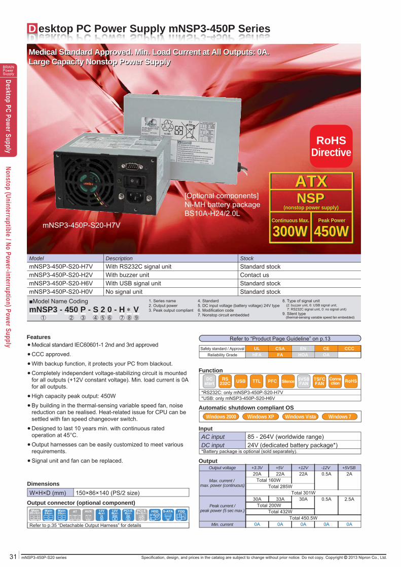
D esktop PC Power Supply mNSP3-450P Series
Model StockDescription
mNSP3-450P-S20-H6V Standard stockWith USB signal unitmNSP3-450P-S20-H0V Standard stockNo signal unit
mNSP3-450P-S20-H2V Contact usWith buzzer unitmNSP3-450P-S20-H7V Standard stockWith RS232C signal unit
1. Series name2. Output power3. Peak output compliant
4. Standard5. DC input voltage (battery voltage) 24V type6. Modification code7. Nonstop circuit embedded
8. Type of signal unit (2: buzzer unit, 6: USB signal unit, 7: RS232C signal unit, 0: no signal unit)9. Silent type (thermal-sensing variable speed fan embedded)
■Model Name CodingmNSP3 - 450 P - S 2 0 - H V
① ② ④ ⑦ ⑨③ ⑤ ⑥ ⑧
mNSP3-450P-S20-H7V
Medical Standard Approved. Min. Load Current at All Outputs: 0A.Large Capacity Nonstop Power Supply
[Optional components]Ni-MH battery packageBS10A-H24/2.0L
RoHSDirective
ATXNSPATXNSP
(nonstop power supply)(nonstop power supply)
300W300W 450W450WContinuous Max.Continuous Max. Peak PowerPeak Power
Medical Standard Approved. Min. Load Current at All Outputs: 0A.Large Capacity Nonstop Power Supply
Refer to “Product Page Guideline” on p.13
W×H×D (mm) 150×86×140 (PS/2 size)
Output voltage
Min. current
Max. current / max. power (continuous)
Peak current /peak power (5 sec max.)
+3.3V20A
0A
30A
+12V22A
0A
30ATotal 301W
Total 450.5W
+5V22A
0A
Total 285W
33A
Total 432W
Total 160W
Total 200W
-12V0.5A
0A
0.5A
+5VSB2A
0A
2.5A
AC input 85 - 264V (worldwide range)DC input*Battery package is optional (sold separately).
24V (dedicated battery package*)
*USB: only mNSP3-450P-S20-H6V*RS232C: only mNSP3-450P-S20-H7V
Safety standard / Approval UL ENCSA CE CCCReliability Grade HFA HOAFA OA
Refer to p.35 “Detachable Output Harness” for details
Windows Vista Windows 7Windows XPWindows 2000
Main24pin
Main20pin
HDD FDDS-ATAAT AUXMain20+4pin
12V4pin
12V8pin
PCI-E6pin
PCI-E6+2pin
Features
Output connector (optional component)
Dimensions
Function
Automatic shutdown compliant OS
Input
Output
Medical standard IEC60601-1 2nd and 3rd approvedCCC approved.With backup function, it protects your PC from blackout.Completely independent voltage-stabilizing circuit is mounted for all outputs (+12V constant voltage). Min. load current is 0A for all outputs.High capacity peak output: 450WBy building in the thermal-sensing variable speed fan, noise reduction can be realised. Heat-related issue for CPU can be settled with fan speed changeover switch.Designed to last 10 years min. with continuous rated operation at 45°C.Output harnesses can be easily customized to meet various requirements.Signal unit and fan can be replaced.
●●●●
●●
●
●
●
RS232C USB PFC Silence 5VSB
FANTSFCFAN RoHSConne
ctionDCstart TTL
BRAINPowerSupplyDesktop PC Power Supply
Nonstop (Uninterruptible / No Power-interruption) Power Supply
mNSP3-450P-S20 seriesSpecification, design, and prices in the catalog are subject to change without prior notice. Do not copy. Copyright 2013 Nipron Co., Ltd. 32
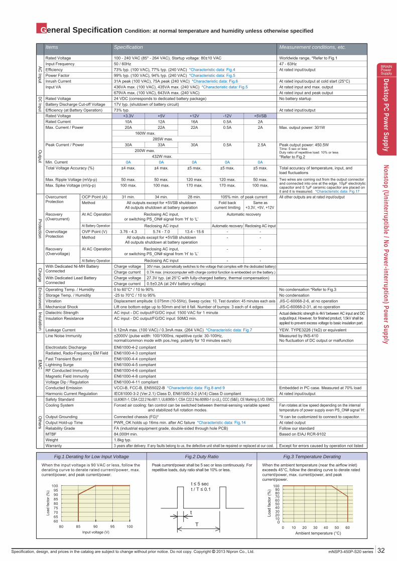
General Specification Condition: at normal temperature and humidity unless otherwise specified
Items Specification Measurement conditions, etc.
When the input voltage is 90 VAC or less, follow the derating curve to derate rated current/power, max. current/power, and peak current/power.
Peak current/power shall be 5 sec or less continuously. For repetitive loads, duty ratio shall be 10% or less.
When the ambient temperature (near the airflow inlet) exceeds 45°C, follow the derating curve to derate rated current/power, max. current/power, and peak current/power.
Fig.1 Derating for Low Input Voltage Fig.3 Temperature DeratingFig.2 Duty Ratio
Rated Voltage 100 - 240 VAC (85* - 264 VAC), Startup voltage: 80±10 VAC Worldwide range, *Refer to Fig.1
Rated Voltage +3.3V +5VSB-12V+12V+5V
285W max.
432W max.
Max. Current / Power 20A 2A0.5A22A22A Max. output power: 301W
OvercurrentProtection
OCP Point (A) 31 min. 105% min. of peak current28 min.34 min. All other outputs are at rated input/output
OvervoltageProtection
OVP Point (V) 3.76 - 4.3 - -13.4 - 15.65.74 - 7.0
Recovery(Overcurrent)
At AC Operation Automatic recoveryReclosing AC input,or switching PS_ON# signal from ‘H’ to ‘L’
Recovery(Overvoltage)
At AC Operation --Reclosing AC input,or switching PS_ON# signal from ‘H’ to ‘L’
Total Voltage Accuracy (%) ±4 max. ±5 max.±5 max.±5 max.±4 max. Total accuracy of temperature, input, andload fluctuations
Max. Spike Voltage (mVp-p) 100 max. 100 max.170 max.170 max.100 max.Two wires are coming out from the output connectorand connected into one at the edge. 10μF electrolyticcapacitor and 0.1μF ceramic capacitor are placed onit and it is measured. *Characteristic data: Fig.17
Max. Ripple Voltage (mVp-p) 50 max. 50 max.120 max.120 max.50 max.
Peak Current / Power 30A 2.5A0.5A30A33A Peak output power: 450.5WTime: 5 sec or lessDuty ratio of repetitive load: 10% or less*Refer to Fig.2
With Dedicated Ni-MH BatteryConnected
Charge voltage 35V max. (automatically switches to the voltage that complies with the dedicated battery)
With Dedicated Lead BatteryConnected
Charge voltage 27.3V typ. (at 25°C with fully-charged battery, thermal compensation)Charge current 0.7A max. (microcomputer with charge control function is embedded on the battery.)
Charge current 0.5±0.2A (at 24V battery voltage)
160W max.
200W max.
Rated Current 10A 2A0.5A16A12A
Method Same as+3.3V, +5V, +12V
Fold backcurrent limiting
All outputs except for +5VSB shutdownAll outputs shutdown at battery operation
Method --All outputs except for +5VSB shutdownAll outputs shutdown at battery operation
At Battery Operation Reclosing AC inputAutomatic recoveryReclosing AC input
At Battery Operation --Reclosing AC input
Min. Current 0A 0A0A0A0A
Efficiency (at Battery Operation) 73% typ. At rated input/outputBattery Discharge Cut-off Voltage 17V typ. (shutdown of battery circuit)Rated Voltage 24 VDC (corresponds to dedicated battery package) No battery startup
Operating Temp. / Humidity 0 to 60°C* / 10 to 90% No condensation *Refer to Fig.3
Line Noise Immunity ±2000V (pulse width: 100/1000ns, repetitive cycle: 30-100Hz,normal/common mode with pos./neg. polarity for 10 minutes each)
Measured by INS-410 No fluctuation of DC output or malfunction
Warranty 3 years after delivery. If any faults belong to us, the defective unit shall be repaired or replaced at our cost. Except for errors caused by operation not listedWeight 1.8kg typ.MTBF 84,000H min. Based on EIAJ RCR-9102Reliability Grade FA (industrial equipment grade, double-sided through hole PCB) Follow our standardOutput Hold-up Time PWR_OK holds up 16ms min. after AC failure *Characteristic data: Fig.14 At rated outputOutput Grounding Connected chassis (FG)* *It can be customized to connect to capacitor.
Cooling System Forced air cooling: fan control can be switched between thermal-sensing variable speed and stabilized full rotation modes.
Fan rotates at low speed depending on the internaltemperature of power supply even PS_ON# signal 'H'.
Harmonic Current Regulation IEC61000-3-2 (Ver.2.1) Class D, EN61000-3-2 (A14) Class D compliant At rated input/outputConducted Emission VCCI-B, FCC-B, EN55022-B *Characteristic data: Fig.8 and 9 Embedded in PC case. Measured at 70% load
Electrostatic Discharge EN61000-4-2 compliant
Voltage Dip / Regulation EN61000-4-11 compliantMagnetic Field Immunity EN61000-4-8 compliantRF Conducted Immunity EN61000-4-6 compliantLightning Surge EN61000-4-5 compliantFast Transient Burst EN61000-4-4 compliantRadiated, Radio-Frequency EM Field EN61000-4-3 compliant
Safety Standard UL60601-1, CSA C22.2 No.601.1, UL60950-1, CSA C22.2 No.60950-1 (c-UL), CCC (S&E), CE Marking (LVD, EMC)
Leakage Current 0.12mA max. (100 VAC) / 0.3mA max. (264 VAC) *Characteristic data: Fig.7 YEW. TYPE3226 (1kΩ) or equivalent
Insulation Resistance AC input - DC output/FG/DC input: 50MΩ min.Dielectric Strength AC input - DC output/FG/DC input: 1500 VAC for 1 minuteMechanical Shock Lift one bottom edge up to 50mm and let it fall. Number of bumps: 3 each of 4 edges JIS-C-60068-2-31, at no operation
Actual dielectric strength is 4kV between AC input and DC output/input. However, for finished product, 1.5kV shall be applied to prevent excess voltage to basic insulation part.
Vibration Displacement amplitude: 0.075mm (10-55Hz), Sweep cycles: 10, Test duration: 45 minutes each axis JIS-C-60068-2-6, at no operationStorage Temp. / Humidity -25 to 70°C / 10 to 95% No condensation
Input VA 436VA max. (100 VAC), 435VA max. (240 VAC) *Characteristic data: Fig.5679VA max. (100 VAC), 643VA max. (240 VAC)
At rated input and max. outputAt rated input and peak output
Inrush Current 31A peak (100 VAC), 75A peak (240 VAC) *Characteristic data: Fig.6 At rated input/output at cold start (25°C)Power Factor 99% typ. (100 VAC), 94% typ. (240 VAC) *Characteristic data: Fig.5Efficiency 73% typ. (100 VAC), 77% typ. (240 VAC) *Characteristic data: Fig.4 At rated input/outputInput Frequency 50 / 60Hz 47 - 63Hz
6065707580859095
100
80 85 90 95 100Input voltage (V)
Load
fact
or (%
)
t
T 0102030405060708090
100
0 10 20 30 40 50 60Ambient temperature (°C)
Load
fact
or (%
)
AC
InputO
utputP
rotectionEnvironm
entC
hargeInsulation
EM
CO
thersD
C Input
t ≤ 5 sect / T ≤ 0.1
33 mNSP3-450P-S20 series Specification, design, and prices in the catalog are subject to change without prior notice. Do not copy. Copyright 2013 Nipron Co., Ltd.
BRAINPowerSupplyDesktop PC Power Supply
Nonstop (Uninterruptible / No Power-interruption) Power Supply
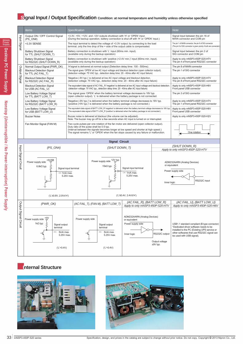
Internal Structure
Signal Input / Output Specification Condition: at normal temperature and humidity unless otherwise specified
Items Specification Note
Input SignalO
utput Signal
Output ON / OFF Control Signal(PS_ON#)
+3.3V, +5V, +12V, and -12V outputs shutdown with ‘H’ or ‘OPEN’ input.(During the backup operation, battery connection is shut off with ‘H’ or ‘OPEN’ input.)
Signal input between the pin 16 ofMAIN connector and COM pin
Battery Shutdown Signalfor RS232C (SHUT DOWN_R)
Battery connection is shutdown with ‘positive (+2.4V min.)’ input (60ms min. input). (available only during the backup operation)
Apply to only mNSP3-450P-S20-H7VThe pin 4 of front panel RS232C connector
Battery Shutdown Signalfor TTL (SHUT DOWN_T)
Battery connection is shutdown with ‘L’ input (60ms min. input).(available only during the backup operation)
Signal input between the pin 2 ofSIG connector and COM pin
+3.3V SENSE The input terminal to detect the voltage of +3.3V output; by connecting to the loadterminal, only the line drop of the + side of the output cable is compensated.
The pin 1 of MAIN connector, the pin 8 of SIG connector(The pin 8 of SIG connector is given priority if both are connected.)
Normal Output Signal (PWR_OK) ‘H’signal is delivered at normal output (Detection delay time: 100 - 500ms). The pin 8 of MAIN connector
Fan Monitor Signal (FAN M) Two cycle pulses per one rotation of the fan motor are delivered (open collector output).Duty ratio of the pulse shall be 0.5 typ. (Interval between the signals becomes longer at low speed and shorter at high speed.)The signal remains 'L' or 'OPEN' when the fan stops caused by any failure or malfunction.
Buzzer Noise Buzzer noise is delivered at blackout (the volume can be adjusted).Note: The buzzer may go off for a few seconds when AC input is turned on or interrupted.
Apply to only mNSP3-450P-S20-H2V
Low Battery Voltage Signalfor USB (BATT LOW_U)
The equivalent data signal of BATT LOW_R 'negative' is delivered when the battery terminal voltage decreases to 18V typ.(The equivalent data signal of BATT LOW_R 'positive' is delivered when the battery package is not connected.)
Apply to only mNSP3-450P-S20-H6VFront panel USB connector
Low Battery Voltage Signalfor RS232C (BATT LOW_R)
'Negative (-9V typ.)' is delivered when the battery terminal voltage decreases to 18V typ.('positive (+9V typ.)' is delivered when the battery package is not connected.)
Apply to only mNSP3-450P-S20-H7VThe pin 1 of front panel RS232C connector
Low Battery Voltage Signalfor TTL (BATT LOW_T)
The signal goes ‘OPEN’ when the battery terminal voltage decreases to 18V typ.(open collector output). ‘L’ is delivered when the battery package is not connected.
The pin 3 of SIG connector
Blackout Detection Signalfor USB (AC FAIL_U)
The equivalent data signal of AC FAIL_R 'negative' is delivered at low AC input voltage and blackout detection. (detection voltage: 75 VAC typ., detection delay time: 20 - 40ms after AC input failure)
Apply to only mNSP3-450P-S20-H6VFront panel USB connector
Blackout Detection Signalfor RS232C (AC FAIL_R)
‘Negative (-9V typ.)’ is delivered at low AC input voltage and blackout detection.(detection voltage: 75 VAC typ., detection delay time: 20 - 40ms after AC input failure)
Apply to only mNSP3-450P-S20-H7VThe pin 8 of front panel RS232C connector
Blackout Detection Signalfor TTL (AC FAIL_T)
The signal goes ‘OPEN' at low AC input voltage and blackout detection (open collector output).(detection voltage: 75 VAC typ., detection delay time: 20 - 40ms after AC input failure)
The pin 1 of SIG connector
One rotation
Input Signal Circuit
Output Signal C
ircuit
Signal Circuit
(PS_ON#) (SHUT DOWN_T) (SHUT DOWN_R)Apply to only mNSP3-450P-S20-H7V
(PWR_OK) (AC FAIL_T), (FAN M), (BATT LOW_T) (AC FAIL_R), (BATT LOW_R)Apply to only mNSP3-450P-S20-H7V
(AC FAIL_U), (BATT LOW_U)Apply to only mNSP3-450P-S20-H6V
(‘L’≤0.8V, 2.0V≤‘H’)
Power supply side+5VSB
Signal input terminal
1mA max.5.25V max.
6.8kΩ typ.
(‘L’≤0.4V, 2.4V≤‘H’)
Power supply side 12V typ
Signal input terminal
1mA max.5.25V max.
15kΩ typ.
(‘L’<0.4V)
Power supply side +5V
Signal output terminal
5mA max.5.25V max.
1kΩ typ
(‘L’<0.4V)
Power supply side
Signal output terminal
5mA max.5.25V max.
USB1.1 standard compliant (B type connector) *Dedicated driver software needs to be installed to the PC (Existing UPS service or other softwares that use RS232C signal can be used with USB signal).
ADM232AARN (Analog Devices)or equivalent
Inner logic
Power supply side
RS232C input
ADM232AARN (Analog Devices)or equivalent
Inner logic
Power supply side
RS232C output
Output voltage±9V typ.
34mNSP3-450P-S20 seriesSpecification, design, and prices in the catalog are subject to change without prior notice. Do not copy. Copyright 2013 Nipron Co., Ltd.
BRAINPowerSupplyDesktop PC Power Supply
Nonstop (Uninterruptible / No Power-interruption) Power Supply
1ms min.
ACInput voltage
DCInput voltageBATT
PS_ON#signal
AC FAIL
All output voltages(except for +5VSB)
+5VSBoutput voltage
1
0
1
0
1
0
1
0
H
L
H
L
H
L
H
L
POWER ONAC operation
Instantaneousblackout AC operationBlackout AC recovery Blackout
Backup operation
DC input (at accident)
20msmax.
100 - 500ms
100 - 500ms
100 - 500ms
20msmin.
SHUTDOWN
H
L
18V typ.
20 - 40ms
20 - 40ms
20 - 40ms
PWR_OKsignal
BATTLOW
TTL
sign
al
RS23
2C s
igna
l
-(*1)
+(*1)
-(*1)
+(*1)
-(*2)
+(*2)
60ms min.
1ms min.
Undefined
100 - 500ms 100 - 500ms100 - 500ms
(1)
(2)
(3)
(4)
(5)
(6)
(7)
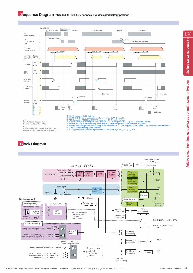
(1) With AC input, only +5VSB starts up. (2) With PS_ON# ‘L’ input, all outputs start up. After 100 - 500ms, PWR_OK goes ‘H'.(3) AC FAIL ‘negative (RS232C)’ and ‘H (TTL)’ are delivered 20 - 40ms after blackout.(4) At blackout, all outputs including +5VSB shut down with SHUT DOWN ‘positive (RS232C)’ or ‘L (TTL)’ input of 60ms min.(5) When AC input and all outputs including +5VSB start up, all outputs except for +5VSB shutdown with PS_ON# ‘H'.(6) When the battery voltage decreases to 18V typ. at backup operation, BATT LOW ‘negative (RS232C)’ and ‘H (TTL)’ are delivered; after it decreases to 17V typ., all outputs including +5VSB shutdown. (7) At AC input, the output does not change even SHUT DOWN ‘positive (RS232C)’ or ‘L (TTL)' input.
(*1)Negative signal output is -9V typ.Positive signal output is +9V typ.(*2)Negative signal input should be +0.4V to -20V.Positive signal output should be +2.8V to +20V.
Dropper
SU-RS3 (RS232C)
+5VSB
Power supply SW
-12V
+12V
+3. 3V
+5V
Noisefilter
Rectifyingcircuit PFC
PWMcontrol circuit
Battery input
Auxiliarypower supply
Charger
AC sideinverter
Battery sideinverter
InverterRectifying/smoothing
Rectifying/smoothing
GND
AC L
AC N
FG
AC sidedrive circuit
Mag. amp.rectifying/smoothing
Battery shutdown signal / SHUT DOWN
Blackout detection signal / AC FAIL Low battery voltage signal / BATT LOW
Signal Connector –1 (TTL input / output signal)
Battery shutdown signal / SHUT DOWN
Blackout detection signal / AC FAIL Low battery voltage signal / BATT LOW
Fan monitor signal / FAN M
PS _ON# (Remote ON / OFF)
PW R_OK (Power Good)
RS232Cdriver
OV detection
BATT LOW
FAN M
SHUT DOWNAC FAIL BATT LOW FAN M
SHUT DOWN
AC FAIL
Mag. amp.rectifying/smoothing
Mag. amp.rectifying/smoothing
Dropper
Resonancecircuit
BATT detection
FAN
FAN SPEED SW
4
81
2
346
Battery sidedrive circuit
D-sub(9-pin)
SU-US 2 ( USB )
USB(B)
SU-BU (buzzer)
USBdriver
Oscillator (2.8kHz)
Adjusting volume
[Replaceable part]
A buzzer goes off atblackout
*Types of USB outputsSHUT DOWN AC FAIL BATT LOW
*
Connect tochassis
Speed control
Rectifying/smoothing
100 - 500ms
Sequence Diagram mNSP3-450P-S20-H7V connected w/ dedicated battery package
Block Diagram
85 - 264 VAC
24 VDC
35 mNSP3-450P-S20 series
BRAINPowerSupplyDesktop PC Power Supply
Nonstop (Uninterruptible / No Power-interruption) Power Supply
Specification, design, and prices in the catalog are subject to change without prior notice. Do not copy. Copyright 2013 Nipron Co., Ltd.
ContentName of manufacturerModelInput / output ratingOthers
Label attached
Label attached
ContentProduction numberREV.Others
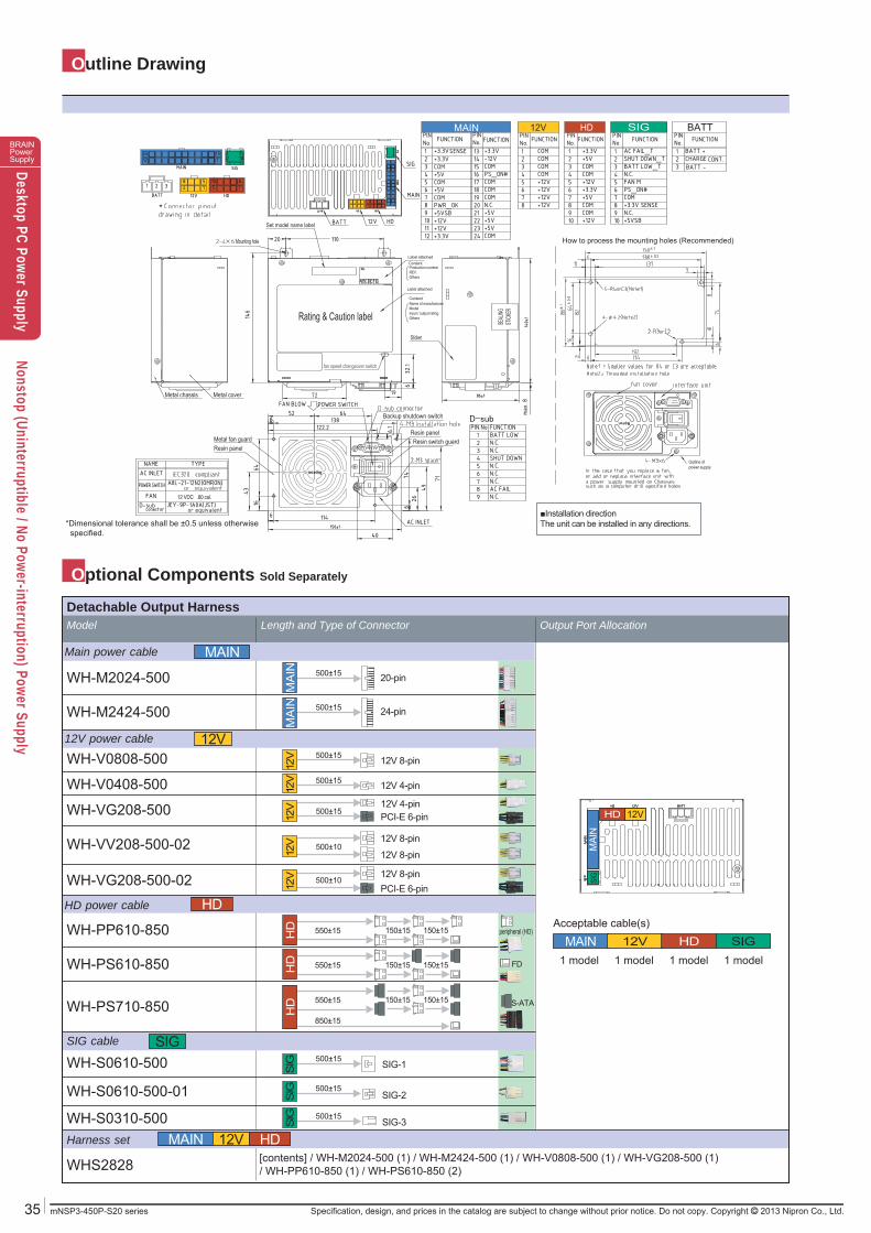
Outline Drawing
MAIN
12V
SIG
HD
WH-M2024-500 500±15 20-pin
WH-VG208-500
WH-V0408-500
WH-M2424-500 500±15 24-pin
WH-S0310-500
WH-S0610-500-01
WH-S0610-500
WHS2828
peripheral (HD)
FD
S-ATA
500±15 12V 4-pin
WH-PP610-850
WH-PS610-850
WH-PS710-850
500±1512V 4-pinPCI-E 6-pin
500±10PCI-E 6-pin
150±15 150±15550±15
150±15 150±15550±15
150±15 150±15550±15
850±15
SIG-1500±15
SIG-2500±15
SIG-3500±15
WH-V0808-500 500±15 12V 8-pin
SIG
HD 12V
MAI
N
WH-VV208-500-02
WH-VG208-500-02
12V 8-pin500±10
12V 8-pin
12V 8-pin
MAIN 12V HD SIG1 model 1 model1 model1 model
Acceptable cable(s)
MAIN 12V HD
MA
INM
AIN
12V
12V
12V
12V
12V
HD
HD
HD
SIG
SIG
SIG
Model Length and Type of Connector Output Port Allocation
Main power cable
Harness set
12V power cable
SIG cable
HD power cable
[contents] / WH-M2024-500 (1) / WH-M2424-500 (1) / WH-V0808-500 (1) / WH-VG208-500 (1) / WH-PP610-850 (1) / WH-PS610-850 (2)
Detachable Output Harness
HD12VMAIN BATTSIG
Optional Components Sold Separately
How to process the mounting holes (Recommended)
Outline of power supply
■Installation directionThe unit can be installed in any directions.
SEAL
INGST
ICKERRating & Caution label
*Dimensional tolerance shall be ±0.5 unless otherwise specified.
*
Sticker
Mounting hole
fan speed changeover switchfan speed changeover switch
Set model name label
Metal chassis
Metal fan guard
Backup shutdown switch
Resin switch guardResin panel
Resin panel
Metal cover
12 VDC .80 cal.
36mNSP3-450P-S20 series
BRAINPowerSupplyDesktop PC Power Supply
Nonstop (Uninterruptible / No Power-interruption) Power Supply
Specification, design, and prices in the catalog are subject to change without prior notice. Do not copy. Copyright 2013 Nipron Co., Ltd.
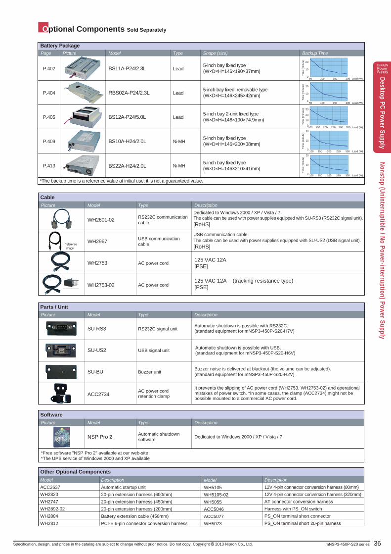
Optional Components Sold Separately
*The backup time is a reference value at initial use; it is not a guaranteed value.
P.402 BS11A-P24/2.3L 5-inch bay fixed type(W×D×H=146×190×37mm)
P.409
P.413
BS10A-H24/2.0L
P.405 BS12A-P24/5.0L
P.404 RBS02A-P24/2.3L
BS22A-H24/2.0L
ModelACC2637WH2820WH2747WH2892-02WH2884WH2812
DescriptionAutomatic startup unit20-pin extension harness (600mm) 20-pin extension harness (450mm) 20-pin extension harness (200mm) Battery extension cable (450mm) PCI-E 6-pin connector conversion harness
ModelWH5105WH5105-02WH5055ACC5046ACC5077WH5073
Description12V 4-pin connector conversion harness (80mm) 12V 4-pin connector conversion harness (320mm) AT connector conversion harnessHarness with PS_ON switchPS_ON terminal short connectorPS_ON terminal short 20-pin harness
Other Optional Components
ACC2734AC power cordretention clamp
It prevents the slipping of AC power cord (WH2753, WH2753-02) and operationalmistakes of power switch. *In some cases, the clamp (ACC2734) might not be possible mounted to a commercial AC power cord.
SU-RS3 RS232C signal unitAutomatic shutdown is possible with RS232C.(standard equipment for mNSP3-450P-S20-H7V)
SU-US2 USB signal unit
SU-BU Buzzer unitBuzzer noise is delivered at blackout (the volume can be adjusted). (standard equipment for mNSP3-450P-S20-H2V)
WH2753
WH2967
125 VAC 12A[PSE]
USB communicationcable
USB communication cableThe cable can be used with power supplies equipped with SU-US2 (USB signal unit). [RoHS]
WH2601-02 RS232C communicationcable
WH2753-02 AC power cord
AC power cord
Automatic shutdownsoftware Dedicated to Windows 2000 / XP / Vista / 7
*Free software "NSP Pro 2" available at our web-site*The UPS service of Windows 2000 and XP available
SoftwarePicture Model Type Description
Picture Model Type Description
Picture Model Type Description
Cable
Tim
e (m
inut
e)
200150100 50 0
10
20
Load (W)
200150100 50 0
10
20
Load (W)
Tim
e (m
inut
e)
Battery PackagePage Picture Model Type Shape (size) Backup Time
Load (W) 350250 300150 200 100 0
10
20
30
Tim
e (m
inut
e)
Tim
e (m
inut
e)
Load (W) 300250200 150 100 0
10
20
Tim
e (m
inut
e)
Load (W) 300250200 150 100 0
10
20
Lead
Ni-MH
Ni-MH
Lead
Lead
5-inch bay fixed type(W×D×H=146×200×38mm)
5-inch bay fixed type(W×D×H=146×210×41mm)
5-inch bay 2-unit fixed type(W×D×H=146×190×74.9mm)
5-inch bay fixed, removable type(W×D×H=146×245×42mm)
125 VAC 12A (tracking resistance type) [PSE]
Parts / Unit
NSP Pro 2
*reference image
fan speed changeover switch
Dedicated to Windows 2000 / XP / Vista / 7. The cable can be used with power supplies equipped with SU-RS3 (RS232C signal unit). [RoHS]
Automatic shutdown is possible with USB.(standard equipment for mNSP3-450P-S20-H6V)
37 mNSP3-450P-S20 series
BRAINPowerSupplyDesktop PC Power Supply
Nonstop (Uninterruptible / No Power-interruption) Power Supply
Specification, design, and prices in the catalog are subject to change without prior notice. Do not copy. Copyright 2013 Nipron Co., Ltd.
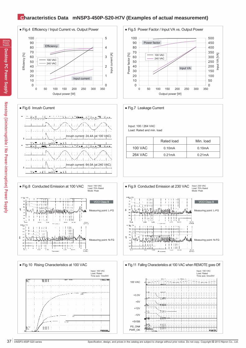
Characteristics Data mNSP3-450P-S20-H7V (Examples of actual measurement)
0102030405060708090
100
0 50 100 150 200 250 300 350050100150200250300350400450500
0102030405060708090
100
0 50 100 150 200 250 300 3500
1
2
3
4
5
VCCI Class BVCCI Class B VCCI Class BVCCI Class B
100 VAC 0.10mA 0.10mA
264 VAC 0.21mA 0.21mA
Rated load Min. load
Measuring point: L-FG
Measuring point: N-FGMeasuring point: N-FG
Measuring point: L-FG
Output
100 VAC240 VAC
100 VAC240 VAC
● Fig.5 Power Factor / Input VA vs. Output Power● Fig.4 Efficiency / Input Current vs. Output Power
● Fig.6 Inrush Current
● Fig.9 Conducted Emission at 230 VAC● Fig.8 Conducted Emission at 100 VAC
Input: 100 VACLoad: 70% RatedMode: Peak
Input: 230 VACLoad: 70% RatedMode: Peak
● Fig.7 Leakage Current
● Fig.11 Falling Characteristics at 100 VAC when REMOTE goes Off ● Fig.10 Rising Characteristics at 100 VAC
+5V
100 VAC
+3.3V
+12V
-12V
+5VSB
PWR_OKPS_ON#
Efficiency
Input current
Power factor
Input VAEffi
cien
cy [%
]
Output power [W]
Inpu
t cur
rent
[A]
Pow
er fa
ctor
[%]
Output power [W]
Inpu
t VA
[VA
]
Inrush current: 24.4A (at 100 VAC)
Inrush current: 64.0A (at 240 VAC)
Input: 100 / 264 VACLoad: Rated and min. load
Input: 100 VACLoad: RatedTime axis: 1ms/DIV
Input: 100 VACLoad: RatedTime axis: 5ms/DIV
38mNSP3-450P-S20 series
BRAINPowerSupplyDesktop PC Power Supply
Nonstop (Uninterruptible / No Power-interruption) Power Supply
Specification, design, and prices in the catalog are subject to change without prior notice. Do not copy. Copyright 2013 Nipron Co., Ltd.
Characteristics Data mNSP3-450P-S20-H7V (Examples of actual measurement)
+3.3V+5V
+12V
0123456789
10111213
0 5 10 15 20 25 30 35 40 45
3.428 V 3.428 V 3.428 V 3.428 V
85 VAC 100 VAC 132 VAC 176 VAC
3.309 V 3.309 V 3.309 V 3.309 V
3.187 V 3.189 V 3.189 V 3.190 V
5.171 V 5.171 V 5.171 V 5.171 V
5.014 V 5.014 V 5.013 V 5.013 V
4.815 V 4.828 V 4.827 V 4.824 V
12.169 V 12.169 V 12.169 V 12.169 V
12.150 V 12.149 V 12.148 V 12.148 V
11.929 V 11.934 V 11.935 V 11.937 V
3.428 V 3.428 V
240 VAC 264 VAC
3.309 V 3.309 V
3.190 V 3.190 V
5.170 V 5.170 V
5.012 V 5.012 V
4.828 V 4.828 V
12.169 V 12.169 V
12.148 V 12.148 V
11.937 V 11.937 V
020406080
100120140160180
0 100 200 300 400
Expected service life (yr)
VCCI Class B VCCI Class B
Expected service life (yr)
■ Electrolytic capacitors
Intake air temp. 20°C 30°C 40°C 45°C
approx. 121 approx. 60 approx. 30 approx. 21※ Lifetime shall be 15 years at longest due to deterioration of sealing plates.
■ Fan
Ambient temp. 20°C 30°C 40°C 45°C
approx. 17 approx. 17 approx. 17 approx. 14
Input: 100 VACLoad: RatedOperating time: 24 consecutive hours
● Fig.18 Ambient Temperature vs. Expected Service Life
Input: 100 VAC
● Fig.19 Over Current Protection (V-I Characteristic)
OutputOutput Rated loadMin. load
Peak load
+12V output 0A 16A 30A+5V output 0A 12A 33A
+3.3V output 0A 10A 30A
PWR_OKOutput voltageAC FAIL
+5V
240 VAC
+3.3V
+12V
-12V
+5VSB
PWR_OKPS_ON#
PWR_OK: the point that PWR_OK signal goes to “L”Output voltage: the point any output voltage decreases to 95% except +5VSBAC FAIL: the point that AC FAIL signal is delivered
● Fig.13 Falling Characteristics at 240 VAC when REMOTE goes Off ● Fig.12 Rising Characteristics at 240 VAC
● Fig.14 Output Hold-up Time vs. Output Power
Output power [W]
Hol
d-up
tim
e [m
s]
● Fig.16 Output Voltage Regulation ● Fig.17 Ripple and Spike Voltage
● Fig.15 Dynamic Load Fluctuation Characteristics at 1kHz
+12V output voltage(500mV/DIV)
+12V output current(25A/DIV)
+5V output voltage(50mV/DIV)
+3.3V output voltage(50mV/DIV)
Output current [A]
Out
put v
olta
ge [V
]
Input: 240 VACLoad: RatedTime axis: 1ms/DIV
Input: 240 VACLoad: RatedTime axis: 5ms/DIV
Input: 100 VACLoad: RatedTime axis: 200μs/DIV
Input: 100 VACLoad: RatedTime axis: 2μs/DIV
AC input voltage
+12V output (rated load)
+12V output (min. load)
+12V output (peak load)
+5V output (rated load)
+5V output (min. load)
+5V output (peak load)
+3.3V output (rated load)
+3.3V output (min. load)
+3.3V output (peak load)
+3.3V output voltage(5mV/DIV)
+5V output voltage(5mV/DIV)
+12V output voltage(20mV/DIV)
Recommended