Bulletin 700-P (10A), 700DC-P (10A), 700-PL (10A), 700-PT (10A), 700-PK (20A), 700DC-PK (20A), 700-PH (35A), 700DC-PH (35A), 700-CP1, 700-CPM, 700-CPR, 700-CPHIndustrial Control Relay and Accessory Installation Instructions
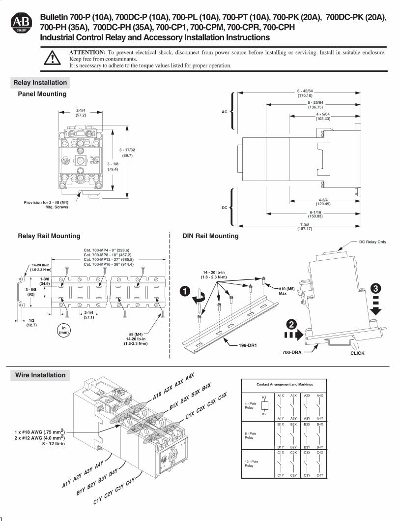
Relay Rail Mounting
Panel Mounting
Relay Installation
ATTENTION: To prevent electrical shock, disconnect from power source before installing or servicing. Install in suitable enclosure. Keep free from contaminants.It is necessary to adhere to the torque values listed for proper operation.
3 - 5/8(92)
1/2(12.7)
in(mm)
#10 (M5)Max
14 - 20 lb-in(1.6 - 2.3 N-m)
2-1/4(57.1)
1-3/8(34.9)
14-20 lb-in(1.6-2.3 N-m)
#8 (M4)14-20 lb-in
(1.6-2.3 N-m)
(89.7)3 - 17/32
(79.4)3 - 1/8
(57.2)2-1/4
Provision for 2 - #8 (M4)Mtg. Screws
Cat. 700-MP4 - 9" (228.6) Cat. 700-MP8 - 18" (457.2)Cat. 700-MP12 - 27" (685.8)Cat. 700-MP16 - 36" (914.4)
199-DR1
700-DRA CLICK
DIN Rail Mounting
DC
AC 4 - 5/64(103.43)
5 - 25/64(136.75)
6 - 45/64(170.10)
(187.17)7-3/8
DC Relay Only
(153.83)6-1/16
(120.49)4-3/4
2
1 3
Wire Installation
4 - PoleRelay
8 - PoleRelay
12 - PoleRelay
Contact Arrangement and Markings
K1A1X
A1YK2
A2X
A2Y
A3X
A3Y
A4X
A4Y
B1X
B1Y
B2X
B2Y
B3X
B3Y
B4X
B4Y
C1X
C1Y
C2X
C2Y
C3X
C3Y
C4X
C4Y
1 x #18 AWG (.75 mm2)2 x #12 AWG (4.0 mm2)
8 - 12 lb-in
A1X A2X A3X A4X
B1X B2X B3X B4X
C1X C2X C3X C4X
A1Y A2Y A3Y A4Y
B1Y B2Y B3Y B4Y
C1Y C2Y C3Y C4Y
B-vertical.ai
1 2 3 4 5 6 7 8
A
B
C
D
E
F
G
H
CONFIDENTIAL AND PROPRIETARY INFORMATION. THIS DOCUMENT CONTAINS CONFIDENTIAL AND PROPRIETARY INFORMATION OF
ROCKWELL AUTOMATION, INC. AND MAY NOT BE USED, COPIED OR DISCLOSED TO OTHERS, EXCEPT WITH THE AUTHORIZED WRITTEN
PERMISSION OF ROCKWELL AUTOMATION, INC.
BULLETIN 700P INSTALLATION INSTRUCTION SHEET
10000005242
Sheet
Size Ver
Of 41
B 00Dr. DateG. USHAKOW 08-17-07
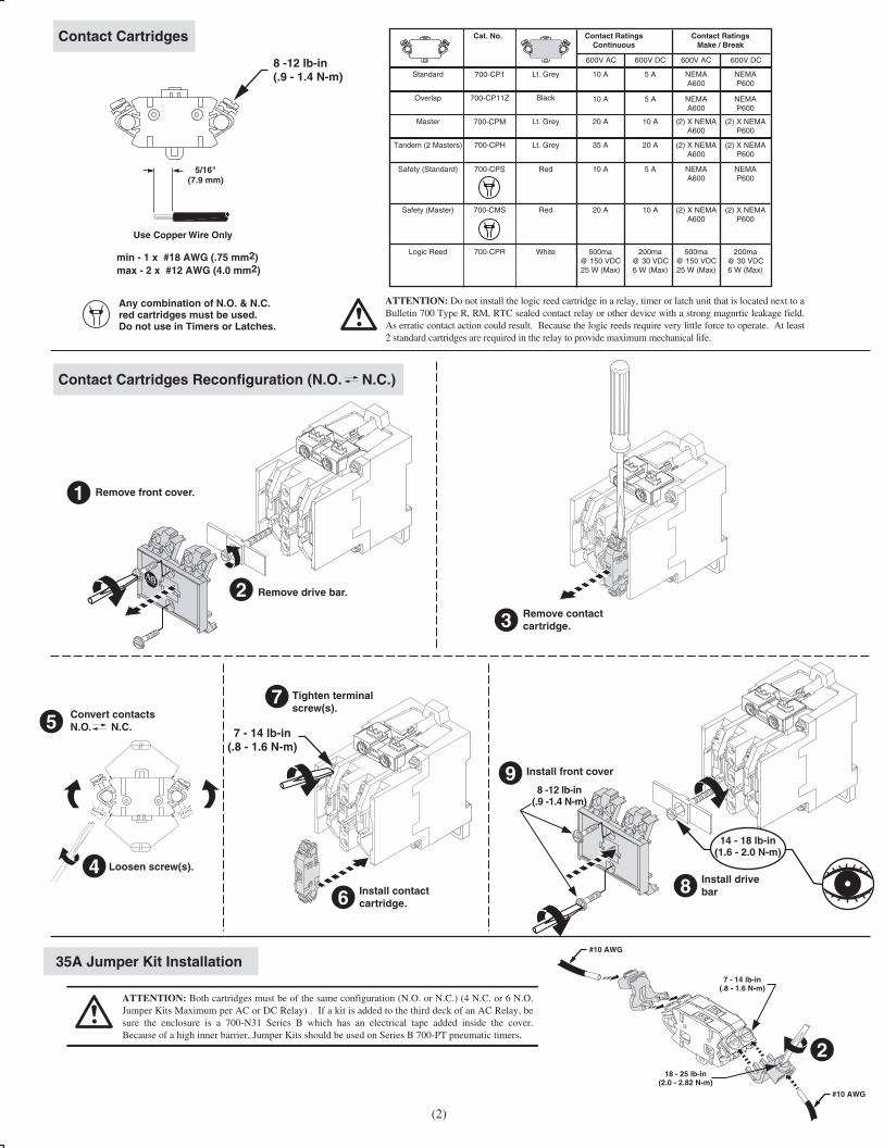
Contact Cartridges
Contact Cartridges Reconfiguration (N.O. N.C.)
8 -12 lb-in(.9 - 1.4 N-m)
min - 1 x #18 AWG (.75 mm2)max - 2 x #12 AWG (4.0 mm2)
7 - 14 lb-in(.8 - 1.6 N-m)
5/16"(7.9 mm)
Use Copper Wire Only
14 - 18 lb-in(1.6 - 2.0 N-m)
Remove front cover.
Remove drive bar.
Loosen screw(s).
Convert contactsN.O. N.C.
Install contactcartridge.
1
2
4
5
Tighten terminal screw(s).
7
6Install drivebar8
2
Install front cover9
Remove contactcartridge.3
Any combination of N.O. & N.C.red cartridges must be used.Do not use in Timers or Latches.
Cat. No. Contact RatingsContinuous
Contact RatingsMake / Break
10 A
600V AC
10 A
20 A
Lt. Grey
Black
Lt. Grey
Standard
Overlap
Master
700-CP1
700-CP11Z
700-CPM
35 ALt. GreyTandem (2 Masters) 700-CPH
RedSafety (Standard) 700-CPS 10 A
RedSafety (Master) 700-CMS 20 A
600V AC
NEMAA600
NEMAA600
(2) X NEMAA600
(2) X NEMAA600
NEMAA600
(2) X NEMAA600
600V DC
NEMAP600
NEMAP600
(2) X NEMAP600
(2) X NEMAP600
NEMAP600
(2) X NEMAP600
WhiteLogic Reed 700-CPR 500ma@ 150 VDC25 W (Max)
500ma@ 150 VDC25 W (Max)
200ma@ 30 VDC6 W (Max)
5 A
600V DC
5 A
10 A
20 A
5 A
10 A
200ma@ 30 VDC6 W (Max)
ATTENTION: Do not install the logic reed cartridge in a relay, timer or latch unit that is located next to a Bulletin 700 Type R, RM, RTC sealed contact relay or other device with a strong magnrtic leakage field. As erratic contact action could result. Because the logic reeds require very little force to operate. At least 2 standard cartridges are required in the relay to provide maximum mechanical life.
35A Jumper Kit Installation
ATTENTION: Both cartridges must be of the same configuration (N.O. or N.C.) (4 N.C. or 6 N.O. Jumper Kits Maximum per AC or DC Relay) . If a kit is added to the third deck of an AC Relay, be sure the enclosure is a 700-N31 Series B which has an electrical tape added inside the cover. Because of a high inner barrier, Jumper Kits should be used on Series B 700-PT pneumatic timers.
(2)
7 - 14 lb-in(.8 - 1.6 N-m)
18 - 25 lb-in(2.0 - 2.82 N-m)
#10 AWG
#10 AWG
8 -12 lb-in(.9 -1.4 N-m)
B-vertical.ai
1 2 3 4 5 6 7 8
A
B
C
D
E
F
G
H
CONFIDENTIAL AND PROPRIETARY INFORMATION. THIS DOCUMENT CONTAINS CONFIDENTIAL AND PROPRIETARY INFORMATION OF
ROCKWELL AUTOMATION, INC. AND MAY NOT BE USED, COPIED OR DISCLOSED TO OTHERS, EXCEPT WITH THE AUTHORIZED WRITTEN
PERMISSION OF ROCKWELL AUTOMATION, INC.
BULLETIN 700P INSTALLATION INSTRUCTION SHEET
10000005242
Sheet
Size Ver
Of 42
B 00Dr. Date- - - - - - - - - - - -
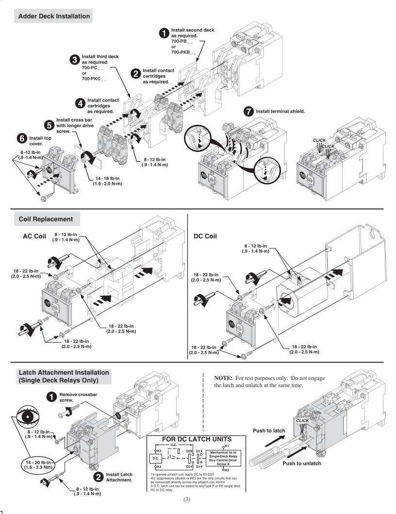
18 - 22 lb-in(2.0 - 2.5 N-m)
18 - 22 lb-in(2.0 - 2.5 N-m)
AC Coil DC Coil
CLICKCLICK
Adder Deck Installation
Install top cover.
6
Install terminal shield.7
Install second deckas required.700-PB_ _or700-PKB_ _
1
Install third deckas required.700-PC_ _or700-PKC_ _
3Install contact cartridgesas required.
2
Install contact cartridgesas required.
4
Install cross barwith longer drivescrew.
5
Coil Replacement
14 - 18 lb-in(1.6 - 2.0 N-m)
8 - 12 lb-in(.9 - 1.4 N-m)
8 -12 lb-in(.9 -1.4 N-m)
(3)
8 - 12 lb-in(.9 - 1.4 N-m)
Latch Attachment Installation(Single Deck Relays Only)
Push to latch
Push to unlatch
CLICK
D.C.
D.C.
Mechanical tie toSingle-Deck Relaythru Central Drive
Screw K
K3
K4
K1
K2D2Y D1Y
D2X D1X
To operate unlatch coil, apply DC to K3-D2XArc suppressors (diodes or RC) are the only circuits that can be connected directly across the unlatch coil, K3-K4A D.C. latch unit can be added to anyType P or PK single deck AC or DC relay.
Remove crossbar screw.1
8 - 12 lb-in(.9 - 1.4 N-m)
8 - 12 lb-in(.9 - 1.4 N-m)
14 - 20 lb-in(1.6 - 2.3 Nm)
Install LatchAttachment.2
2
FOR DC LATCH UNITS
18 - 22 lb-in(2.0 - 2.5 N-m)
8 - 12 lb-in(.9 - 1.4 N-m)
18 - 22 lb-in(2.0 - 2.5 N-m)
18 - 22 lb-in(2.0 - 2.5 N-m)
18 - 22 lb-in(2.0 - 2.5 N-m)
NOTE: For test putposes only. Do not engagethe latch and unlatch at the same time.
B-vertical.ai
1 2 3 4 5 6 7 8
A
B
C
D
E
F
G
H
CONFIDENTIAL AND PROPRIETARY INFORMATION. THIS DOCUMENT CONTAINS CONFIDENTIAL AND PROPRIETARY INFORMATION OF
ROCKWELL AUTOMATION, INC. AND MAY NOT BE USED, COPIED OR DISCLOSED TO OTHERS, EXCEPT WITH THE AUTHORIZED WRITTEN
PERMISSION OF ROCKWELL AUTOMATION, INC.
BULLETIN 700P INSTALLATION INSTRUCTION SHEET
10000005242
Sheet
Size Ver
Of 43
B 00Dr. Date- - - - - - - - - - - -
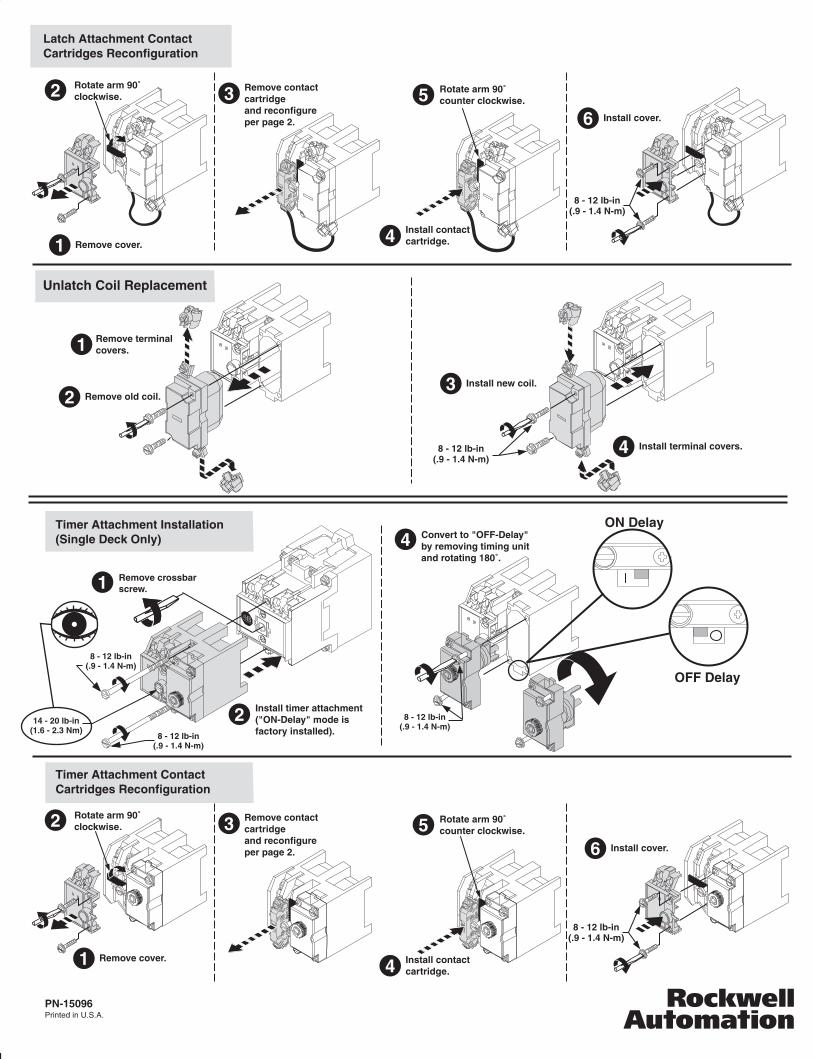
Latch Attachment Contact Cartridges Reconfiguration
Install contactcartridge.4
5Install cover.6
2
Unlatch Coil Replacement
14 - 20 lb-in(1.6 - 2.3 Nm)
8 - 12 lb-in(.9 - 1.4 N-m)
8 - 12 lb-in(.9 - 1.4 N-m)
8 - 12 lb-in(.9 - 1.4 N-m)
Timer Attachment Installation (Single Deck Only)
Timer Attachment Contact Cartridges Reconfiguration
Remove crossbar screw.1
Remove cover.1
1
Remove old coil.2Install new coil.3
Install terminal covers.4
Remove terminalcovers.
2 Rotate arm 90˚clockwise.
2
Remove contactcartridgeand reconfigureper page 2.
3 Rotate arm 90˚counter clockwise.
Install contactcartridge.4
5Install cover.
Install timer attachment("ON-Delay" mode is factory installed).
4 Convert to "OFF-Delay"by removing timing unitand rotating 180˚.
6
Remove cover.1
2 Rotate arm 90˚clockwise.
Remove contactcartridgeand reconfigureper page 2.
3 Rotate arm 90˚counter clockwise.
PN-15096Printed in U.S.A.
OFF Delay
ON Delay
8 - 12 lb-in(.9 - 1.4 N-m)
8 - 12 lb-in(.9 - 1.4 N-m)
8 - 12 lb-in(.9 - 1.4 N-m)
B-vertical.ai
1 2 3 4 5 6 7 8
A
B
C
D
E
F
G
H
CONFIDENTIAL AND PROPRIETARY INFORMATION. THIS DOCUMENT CONTAINS CONFIDENTIAL AND PROPRIETARY INFORMATION OF
ROCKWELL AUTOMATION, INC. AND MAY NOT BE USED, COPIED OR DISCLOSED TO OTHERS, EXCEPT WITH THE AUTHORIZED WRITTEN
PERMISSION OF ROCKWELL AUTOMATION, INC.
BULLETIN 700P INSTALLATION INSTRUCTION SHEET
10000005242
Sheet
Size Ver
Of 44
B 00Dr. Date- - - - - - - - - - - -
MATERIALNO. MATERIAL
SIZEFOLDFLAT
17" W x 11" H 4-1/4" W x 2-3/4" HTWO SIDES PRINTEDBODY STOCK WHITE
BODY INK BLACKPN-15096
SUPERSEDES
- - - - - - - -
Recommended