8/14/2019 Coil Heater Installation Guide
http://slidepdf.com/reader/full/coil-heater-installation-guide 1/1
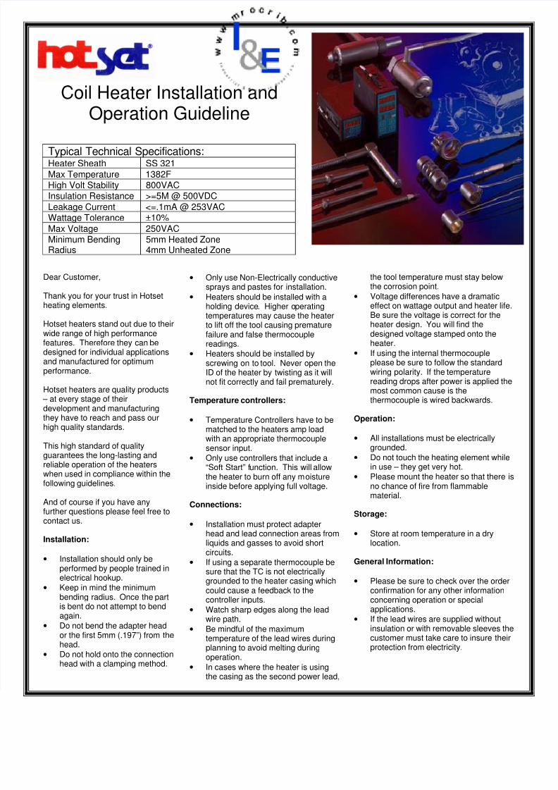
Coil Heater Installation and
Operation Guideline
Typical Technical Specifications:Heater Sheath SS 321
Max Temperature 1382FHigh Volt Stability 800VACInsulation Resistance >=5M @ 500VDC
Leakage Current <=.1mA @ 253VACWattage Tolerance ±10%
Max Voltage 250VACMinimum BendingRadius
5mm Heated Zone4mm Unheated Zone
Dear Customer,
Thank you for your trust in Hotsetheating elements.
Hotset heaters stand out due to theirwide range of high performancefeatures. Therefore they can bedesigned for individual applicationsand manufactured for optimumperformance.
Hotset heaters are quality products – at every stage of theirdevelopment and manufacturing
they have to reach and pass ourhigh quality standards.
This high standard of qualityguarantees the long-lasting andreliable operation of the heaterswhen used in compliance within thefollowing guidelines.
And of course if you have anyfurther questions please feel free tocontact us.
Installation:
• Installation should only beperformed by people trained inelectrical hookup.
• Keep in mind the minimumbending radius. Once the partis bent do not attempt to bendagain.
• Do not bend the adapter heador the first 5mm (.197”) from thehead.
• Do not hold onto the connectionhead with a clamping method.
• Only use Non-Electrically conductivesprays and pastes for installation.
• Heaters should be installed with aholding device. Higher operatingtemperatures may cause the heaterto lift off the tool causing prematurefailure and false thermocouplereadings.
• Heaters should be installed byscrewing on to tool. Never open theID of the heater by twisting as it willnot fit correctly and fail prematurely.
Temperature controllers:
• Temperature Controllers have to bematched to the heaters amp loadwith an appropriate thermocouplesensor input.
• Only use controllers that include a“Soft Start” function. This will allowthe heater to burn off any moistureinside before applying full voltage.
Connections:
• Installation must protect adapterhead and lead connection areas fromliquids and gasses to avoid short
circuits.• If using a separate thermocouple be
sure that the TC is not electricallygrounded to the heater casing whichcould cause a feedback to thecontroller inputs.
• Watch sharp edges along the leadwire path.
• Be mindful of the maximumtemperature of the lead wires duringplanning to avoid melting duringoperation.
• In cases where the heater is usingthe casing as the second power lead,
the tool temperature must stay belowthe corrosion point.
• Voltage differences have a dramaticeffect on wattage output and heater life.Be sure the voltage is correct for theheater design. You will find thedesigned voltage stamped onto theheater.
• If using the internal thermocoupleplease be sure to follow the standardwiring polarity. If the temperaturereading drops after power is applied themost common cause is thethermocouple is wired backwards.
Operation:
• All installations must be electricallygrounded.
• Do not touch the heating element whilein use – they get very hot.
• Please mount the heater so that there isno chance of fire from flammablematerial.
Storage:
• Store at room temperature in a drylocation.
General Information:
• Please be sure to check over the orderconfirmation for any other informationconcerning operation or specialapplications.
• If the lead wires are supplied withoutinsulation or with removable sleeves thecustomer must take care to insure theirprotection from electricity.
Recommended