4 A B B R e v i e w 1 / 1 9 9 7
ottbus is a town with about 130,000
inhabitants, situated south-east of Berlin,
close to the border with Poland. The
combined heat and power plant already
existing on the Cottbus site has four
small, conventional coal-fired boilers that
can supply a maximum of 48 MWe and
230 MWth in the form of steam to one
of the two municipal district heating net-
works. The second district heating grid
is supplied with hot water from a pulver-
ized coal-fired power plant in Jänsch-
walde, 9 km from Cottbus. All the plants
burn local brown coal.
The Cottbus plant has a remaining life-
time of less than 30,000 hours and must
be replaced before 2001.
PFBC – the ideal option for
repowering Cottbus
Feasibility studies that had been carried
out showed that PFBC is the ideal sol-
ution under the given circumstances as it
will best allow the required performance
to be achieved.
After offers had been requested from
PFBC suppliers and financing agree-
ments had been organized, the city of
Cottbus awarded ABB Kraftwerke AG of
Mannheim, in April 1996, the contract to
build a new turnkey unit based on pres-
surized fluidized bed technology.
ABB has designed two standard mod-
ules – the P200 and P800 – for PFBC
power plants [2–4]. The P200 module
is used to build plants rated at 70 to
100 MWe (one module) or 140 to
210-MWe plants (two P200 modules
combined with one or two steam tur-
bines). The P800 module is used to build
power plants rated at 350 to 425 MWe.
Cottbus power station will have
one P200 module and two gas-fired
peak-load boilers for a maximum output
of 74 MWe and 220 Mwth.
1
ABB’s PFBC technology has the com-
mercial and technical advantage of being
as yet the only such technology to be
commercially proven. Four plants in the
80-MWe range (P200) are already oper-
ating in various parts of the world and a
larger 360-MWe plant is under construc-
tion.
PFBC was judged to be the best op-
tion since it is a proven yet innovative
technology that permits maximum utili-
zation of the local brown coal whilst en-
suring high efficiency and low environ-
mental impact. This is important, as it
also helps to keep jobs in the area. In ad-
dition, it positions Cottbus as a ‘center of
excellence’ for the use of brown coal.
Project requirements
The plant consists of one P200 mod-
ule operating with separate high-pressure
and low-pressure/intermediate-pressure
steam turbines. The P200 module com-
prises a specially developed PFBC gas
turbine , connected to a pressurized
fluidized bed boiler which generates the
steam. The steam passes to the steam
turbines for power generation, being
afterwards fed into the district heating
system. In addition to the P200 module,
the plant has two gas-fired boilers for use
during periods of high heat demand and
as standby capacity (Table 1).
The Cottbus plant will be delivered
under a turnkey contract which covers
the civil works, district heating connec-
tions, coal and sorbent storage and
transport systems, and electrical and
control systems. The consortium leader
for the turnkey supply is ABB Kraftwerke
AG of Mannheim, ABB Carbon supplying
the PFBC island consisting of com-
bustor, gas turbine and auxiliaries. The
two steam turbines, of type G32 and
VEE63, will be supplied by ABB Tur-
binen Nürnberg GmbH. These two tur-
bines have separate generators so that
each can produce electricity separately.
The electrical equipment and plant con-
3
2
P F B C P O W E R P L A N T S
Pär Almhem
ABB Carbon
Wolfgang Schemenau
ABB Kraftwerke AG
C
Cottbus –first PFBC plantto be firedwith brown coalThe first PFBC power plant to be fired with brown coal is currently under
construction at Cottbus, Germany. With its pressurized fluidized bed
combustion P200 module and two gas-fired peak-load boilers, the new
combined heat and power plant will have a maximum output of 74 MWe
and 220 MWth. It replaces an older pulverized coal plant on the same
site and is designed primarily to supply steam and hot water to the
town’s two district heating grids.
A B B R e v i e w 1 / 1 9 9 7 5
trol system will be supplied by ABB
Cottbus.
A long-term maintenance agreement
was also signed, under which ABB Kraft-
werke Service GmbH, Mannheim, and
ABB Carbon will provide manpower and
parts subject to wear for all scheduled
overhauls over a 15-year period. The ser-
vice agreement also covers operation
and maintenance consultancy as well as
access to ABB specialists.
Site work began in autumn 1996. The
plant is scheduled to be on line in the
summer of 1999.
Architectural considerations
Architects and city planners were
brought into the planning of the power
station from the start to ensure optimum
harmonization of the plant with its sur-
roundings.
The industrial estate on which the
power station stands is only about
2 km east of the ‘Spreeaue’ which cuts
across the town from North to South.
The estate is surrounded by residential
areas.
Due to these circumstances, the city
planners required a compact layout and
design for the plant. Some of the key
requirements were that:
• Full use should be made of the exist-
ing plant site.
• The buildings should be low in height
in order not to obstruct the view from
the nearby residences.
• The plant’s design should combine
discreetness with good architectural
features.
• No unacceptable emissions (including
noise) should be allowed.
The site of the new plant is next to the
existing power station. The available
space is almost square, being 165 m by
185 m. Essential plant parts and build-
ings, such as the coal silos, boiler, gas
turbine and steam turbines, will be adjac-
ent to each other , with transformers,
dust filter and auxiliary boilers close by.
4
The switchgear building, water treatment
and cooling towers are also integrated in
the plant.
Existing rails can be used for transpor-
ting main components, fuel and ash. In
and off loading will be optically and
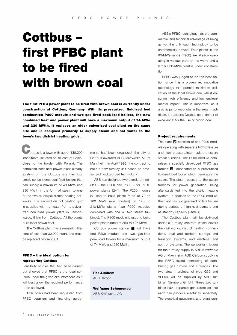
Model of the Cottbus PFBC plant. The combined heat and power utility will have a maximum output of 74 MWe and 220 MWth.
1
Table 1:Technical details of the Cottbus PFBC plant
Combined cycle data
Plant type 1 × P200, combined heat and powerGas turbine 1 × GT35PSteam turbines 1 × G32 + 1 x VEE63Net output 71 MWe/ 40 MWth (low heat demand)
62 MWe/ 90 MWth (high heat demand)74 MWe/220 MWth (+ peak-load boilers)
Technical data (full load, 15 ˚C)
Fuel – PFBC module Lausitz brown coal– peak-load boilers Natural gas or fuel oil, EL
Coal feed system Dry feedCoal feed rate (kg/s) 11.3Sorbent, type Limestone
feedrate (kg/s) 1.0Ash flow (kg/s) 1.8Combustion temperature (˚C) 840–860Steam data (bar/˚C/˚C) 142/537/537Condenser pressure (bar) 0.07
PFBC emission guarantees (weekly average)
SO2 (mg/Nm3, 7 % O2) 115NOx also NO2 (mg/Nm3, 7 % O2) 115CO (mg/Nm3, 7 % O2) 50Dust (mg/Nm3, 7 % O2) 20Max. carbon content in ash (%) 5
P F B C P O W E R P L A N T S
6 A B B R e v i e w 1 / 1 9 9 7
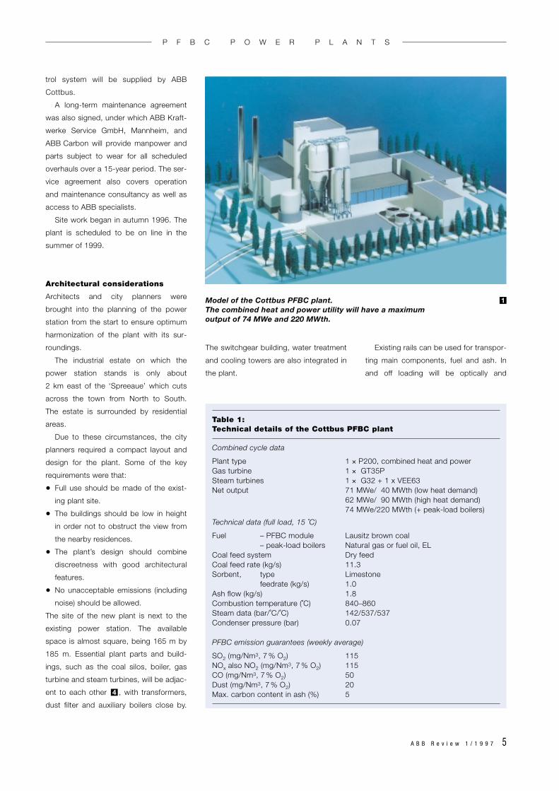
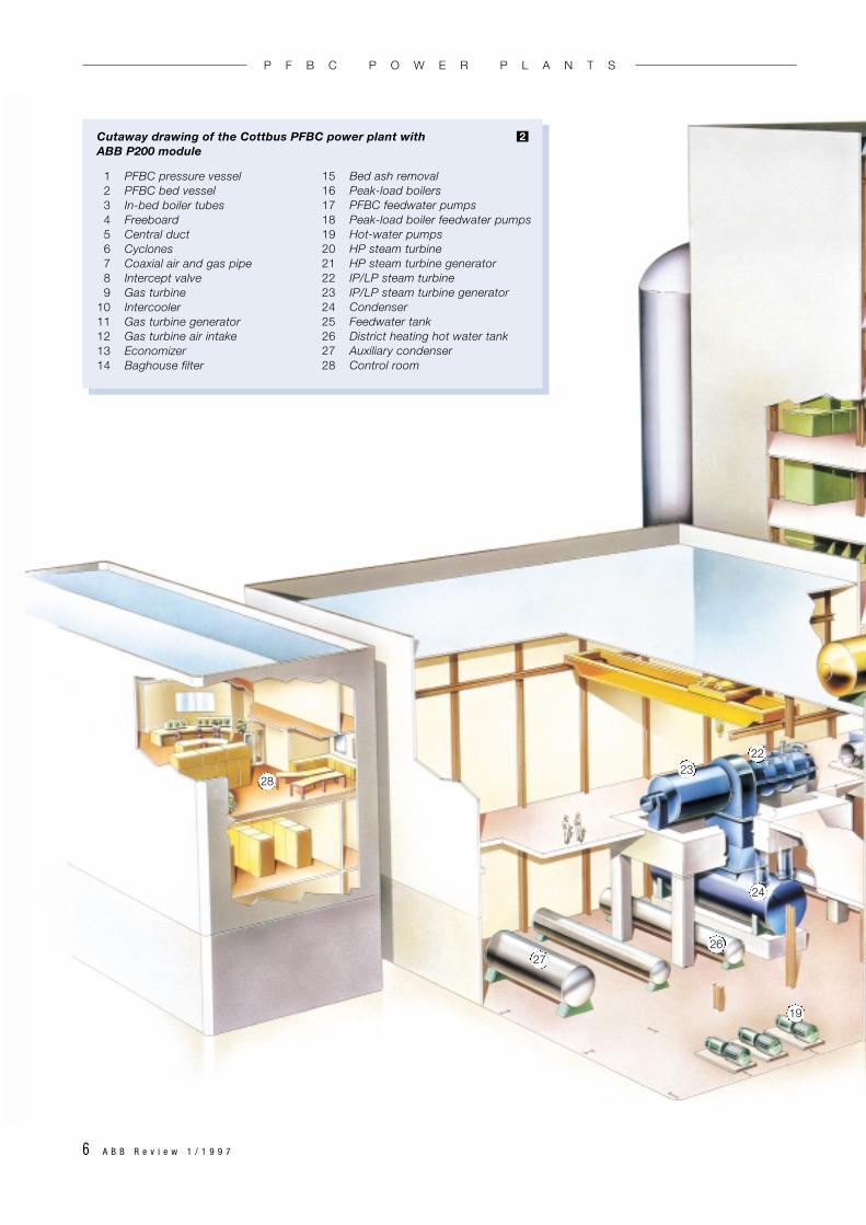
1 PFBC pressure vessel2 PFBC bed vessel3 In-bed boiler tubes4 Freeboard5 Central duct6 Cyclones7 Coaxial air and gas pipe8 Intercept valve9 Gas turbine
10 Intercooler11 Gas turbine generator12 Gas turbine air intake13 Economizer14 Baghouse filter
2
15 Bed ash removal16 Peak-load boilers17 PFBC feedwater pumps18 Peak-load boiler feedwater pumps19 Hot-water pumps20 HP steam turbine21 HP steam turbine generator22 IP/LP steam turbine23 IP/LP steam turbine generator24 Condenser25 Feedwater tank26 District heating hot water tank27 Auxiliary condenser28 Control room
Cutaway drawing of the Cottbus PFBC power plant with ABB P200 module
28
27
2322
24
19
26
P F B C P O W E R P L A N T S
A B B R e v i e w 1 / 1 9 9 7 7
25
2021
17
18
13
10
15
9
14
11
2
3
4
12
8
7
5
61
16
P F B C P O W E R P L A N T S
8 A B B R e v i e w 1 / 1 9 9 7
acoustically shielded from the residential
areas.
Plant operation
The new combined heat and power plant
will be operated primarily according to
demand from the district heating systems
in Cottbus. It is, however, also equipped
with a condenser and cooling towers to
allow electricity production even when
there is no need for district heating. Op-
erating hours for the P200 are expected
to be more than 7,000 h per year, while
operation of the oil or gas-fired peak-load
boilers is estimated at a few hundred
hours per year.
The plant will be equipped with a
state-of-the-art ABB distributed control
system providing a high degree of auto-
mation with maximum support for the
operators. This will allow the plant to be
operated with only 7 to 8 persons on
each shift.
PFBC plants for brown coal
The role of brown coal in
power generation
Brown coal is a major source of electrical
power in Germany and Eastern Europe
and is likely to remain so in the future.
Many of the existing plants, particularly in
former East Germany and the countries
of Eastern Europe, are old and in need
of repowering or upgrading. Domestic
fuels are being used increasingly as they
offer both economic independence and
ease of transportation. In areas where
it is already mined in large quantities,
brown coal will continue to be used for
both repowered and greenfield plants.
There are also enormous unexploited re-
serves in many other parts of the world,
China, USA, UK, New Zealand and Aus-
tralia being some notable examples.
Brown coal is young coal with a low
energy content, high moisture content
(typically 35 to 70 percent), and often a
high ash and sulfur content. Its high sur-
face moisture makes the coal adhesive.
This, combined with its high reactivity
and short ignition time, has frequently led
to handling problems in the past.
Known problems have been high
emissions of NOx, SOx, N2O, CO and
unburned hydrocarbons as well as
corrosion, agglomeration and surface
deposits. PFBC avoids these problems
through its lower combustion tempera-
ture (about 850 ˚C, as opposed to
> 1300 ˚C with conventional boilers) and
its excellent fuel mix in the bed. The
lower temperature prevents the formation
of thermal NOx and reduces the baking of
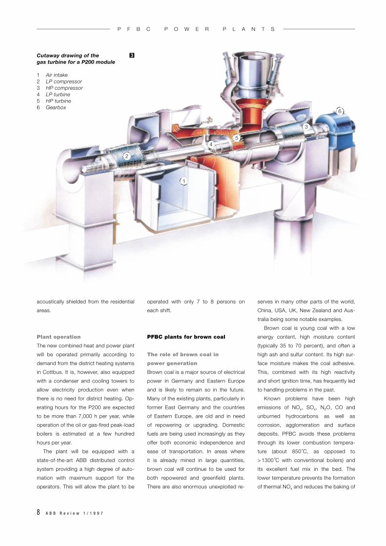
Cutaway drawing of the gas turbine for a P200 module
1 Air intake2 LP compressor3 HP compressor4 LP turbine5 HP turbine6 Gearbox
3
6
2
3
4
1
5
P F B C P O W E R P L A N T S
A B B R e v i e w 1 / 1 9 9 7 9
coal and ash, which is a characteristic of
lignite.
Traditionally, brown coal has been
used in pulverized coal plants, but it has
also been used in fluidized bed plants
in Germany since 1988, mostly with
coal from the Rheinland. Until now the
plants have been of the atmospheric
type, with stationary or circulating beds.
Efficiencies in some plants have been
substantially below 40 percent.
Improved efficiency with
PFBC plants
In addition to a conventional high-value
steam cycle, the arrangement has the
advantage that the hot gases resulting
from the combustion in the PFBC boiler
are cleaned and then used to drive a gas
turbine for additional electricity produc-
tion. In a PFBC plant, the steam turbine
produces about 80 percent of the power
generated, which means that the gas tur-
bine adds a further 20 percent to the
total output. This results in efficiencies
higher than 40 percent.
A cogeneration plant enables highly
efficient, cost-effective energy produc-
tion in the form of electricity, heat and
process steam. Another benefit of PFBC
plants is that they are very compact
and thus suitable for repowering of exist-
ing plants when space is limited.
Because of their low emission levels,
which are well below the most stringent
limits set by the authorities, PFBC plants
can also safely be built in residential
areas.
Since the ash content of the coal
affects the design of the power plant, the
plant must be built to handle the specific
characteristics of the lignite being used.
The Cottbus PFBC plant will be built to
use brown coal from the Lausitz area
(Table 2).
Tests with FBC coal
Lausitz brown coal was tested in ABB
Carbon’s process test facility in Fin-
spong, Sweden, during July and August
1995. The objectives of the tests were
to verify brown coal operation in PFBC,
determine any unexpected phenomena,
and test continuous operation at both full
and part load.
The tests were extremely successful.
There were no problems in burning the
Lausitz brown coal with PFBC, and low
emissions were demonstrated. Despite
Table 2:Analysis of Lausitz brown coal (lifetime average values)
Lower heating value (kJ/kg) 19,000Water (%) 18.5Ash (%) 5.5Volatiles (%) 41Solid coal (%) 34.5Sulfur (%) < 0.8
N
9
10
11
12
7
4
3
6
8
5
2
1
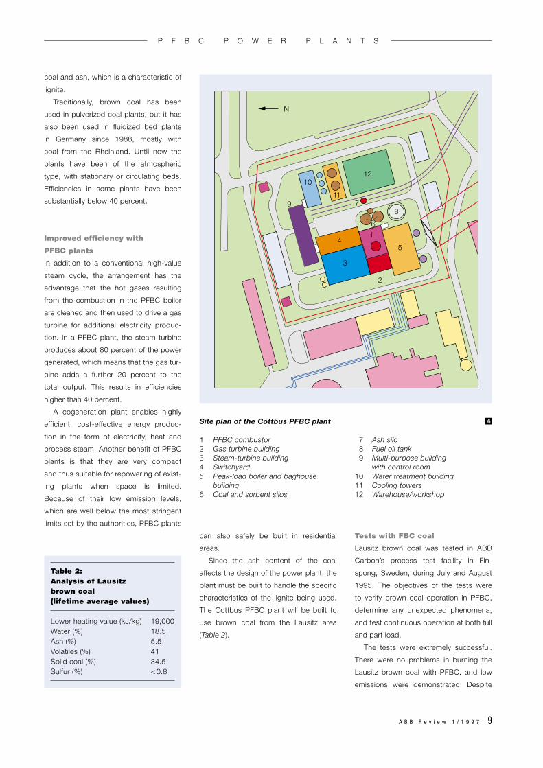
Site plan of the Cottbus PFBC plant
1 PFBC combustor 7 Ash silo2 Gas turbine building 8 Fuel oil tank3 Steam-turbine building 9 Multi-purpose building 4 Switchyard with control room5 Peak-load boiler and baghouse 10 Water treatment building
building 11 Cooling towers6 Coal and sorbent silos 12 Warehouse/workshop
4
P F B C P O W E R P L A N T S

10 A B B R e v i e w 1 / 1 9 9 7
the high reactivity of the coal, no prob-
lems arose with regard to baking of the
ash.
Plant configuration and
operation
The characteristic features of an ABB
PFBC plant are shown in . The gas
turbine and steam turbines in the com-
bined cycle arrangement produce about
20 and 80 percent of the total electrical
output, respectively. The fluidized bed
combustor operates at an elevated
pressure of 12 bar. As already men-
tioned, two standard module sizes based
on ABB PFBC technology are available:
The 70–100 MWe P200 module and the
350–425 MWe P800 module. By combin-
5
ing two or more of these modules, larger
plants can be built.
The combined cycle arrangement at
Cottbus is shown in . The preheated
feedwater enters the combustor and
passes through the bed wall, in-bed tube
bundle, evaporator and superheaters.
The steam thus generated expands
through the HP steam turbine back to the
reheater and continues through the IP
and LP turbine down to the steam tur-
bine condenser.
Combined cycle arrangements with
electric generators being driven by both
a steam turbine and a gas turbine result
in a higher thermal efficiency than with
conventional steam plant. Typically, this
advantage is around 3–4 percentage
points for the same steam conditions,
6
which corresponds to about a 10 percent
saving in fuel. In PFBC repowering appli-
cations in which the steam data of the
old plant are poor, the improvement will
be even greater.
The fluidized bed boiler enables the
plant to burn a very wide range of differ-
ent fuels.
The sulfur emissions are reduced
by 90 to 98 percent during the actual
combustion. As the combustion tem-
perature is relatively low (830–860 ˚C),
NOx emissions are also low and can be
further reduced by non-catalytic gas
phase reduction.
Coal, crushed to the required particle
size, is mixed with sorbent and conveyed
pneumatically into the combustor.
The combustion air enters the process
1
3
7
5
6
4
8
2
GM
G
Schematic showing the concept of a PFBC power plant with combined cycle
1 Mixing of fuel and sorbent 4 Gas turbine-generator set 7 Economizer2 PFBC combustor 5 Steam turbine-generator set 8 Flue-gas filter3 Cyclones 6 Feedwater tank
5
P F B C P O W E R P L A N T S
A B B R e v i e w 1 / 1 9 9 7 11
via the gas turbine low-pressure com-
pressor. It is then cooled in the inter-
cooler in order to keep the temperature
after the high pressure compressor down
to 300 ˚C. The air leaves the high-pres-
sure compressor via a concentric pipe
that discharges into the pressure vessel,
where it acts as the fluidizing and com-
bustion air for the bed. After combustion,
it flows, as hot gas, first into the free-
board above the bed. The combustion
gas is then led through a parallel two-
stage cyclone arrangement to separate
the fly ash. The cleaned gas passes
through the concentric pipe to the gas
turbine, which drives a generator and the
compressors. After passing through the
gas turbine, the gas is fed to the econ-
omizer, which reduces its temperature to
about 140–150 ˚C. Remaining dust is
caught in the baghouse filter. The flue
gas then leaves through the stack.
Ash from the PFBC process
The ash produced by the PFBC process
has two separate sources: fly ash is sep-
arated in the cyclones and the baghouse,
while the bed ash is withdrawn via a lock
hopper system through the bed bottom.
The low process temperature in PFBC
means that the ashes are not fused. In a
fluidized bed, contact between phases is
very good, elevating the combustion effi-
ciency. Consequently, the content of
unburned coal in PFBC ash is very low.
The ash can be harmlessly stored for a
long period of time. After being cooled
with feedwater, the bed ash is pressure-
relieved and fed into the silos. Light-
weight particles are separated from the
flue gas in the two stages of the cyclones
and by the dust filter. Thus, there are
three fractions, known collectively as
‘cyclone ash’.
G
G
G
1
M
2
3
4
5
6
HP 7
LPIP
8
9
10
11
12 12
13
14
15
16
17
18
19
20
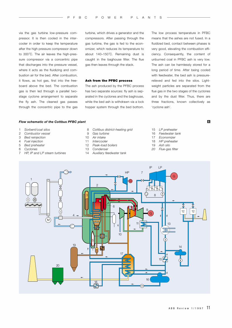
Flow schematic of the Cottbus PFBC plant
1 Sorbent/coal silos 8 Cottbus district-heating grid 15 LP preheater2 Combustor vessel 9 Gas turbine 16 Feedwater tank3 Bed reinjection 10 Air intake 17 Economizer4 Fuel injection 11 Intercooler 18 HP preheater5 Bed preheater 12 Peak-load boilers 19 Ash silo6 Cyclones 13 Condenser 20 Flue-gas filter7 HP, IP and LP steam turbines 14 Auxiliary feedwater tank
6
P F B C P O W E R P L A N T S
12 A B B R e v i e w 1 / 1 9 9 7
The total ash content in Cottbus
brown coal is 5–6 percent, which is fairly
low and easily handled by the standard
cyclone and ash removal systems. Ash
from brown coal fluidized bed combus-
tion has previously been a problem, re-
sulting in high disposal costs. The resi-
dues of PFBC, by contrast, have a variety
of potential uses that minimize the envi-
ronmental impact and improve the overall
economy of the plant.
An article in the next issue of the ABB
Review will show how strong concrete-
like materials with low permeability can be
manufactured from PFBC ashes which
are mixed with water and vibro-com-
pacted. Possible uses are as fill material
or synthetic gravel for road construction
and for stabilizing soil or mine waste, or
as a sealing layer for disposal sites and
for manufacturing concrete.
Operating experience with
PFBC power plants
ABB developed PFBC technology in
collaboration with power plant operators
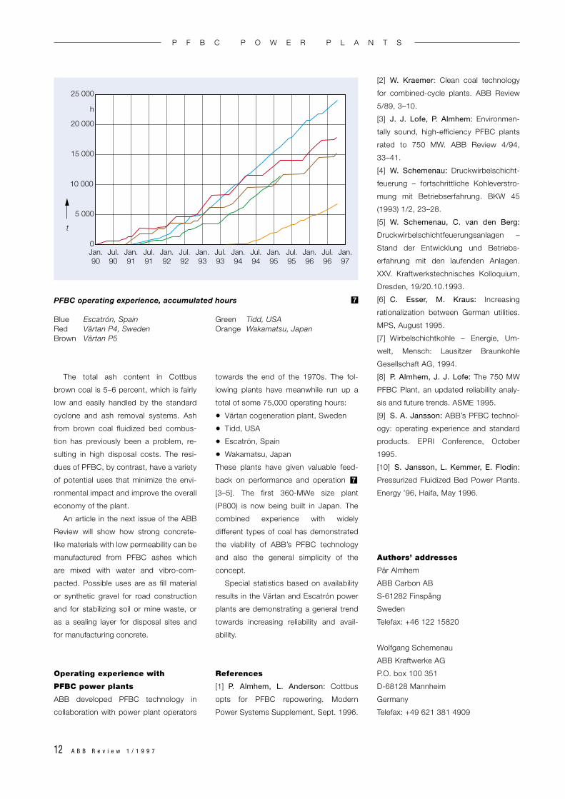
towards the end of the 1970s. The fol-
lowing plants have meanwhile run up a
total of some 75,000 operating hours:
• Värtan cogeneration plant, Sweden
• Tidd, USA
• Escatrón, Spain
• Wakamatsu, Japan
These plants have given valuable feed-
back on performance and operation
[3–5]. The first 360-MWe size plant
(P800) is now being built in Japan. The
combined experience with widely
different types of coal has demonstrated
the viability of ABB’s PFBC technology
and also the general simplicity of the
concept.
Special statistics based on availability
results in the Värtan and Escatrón power
plants are demonstrating a general trend
towards increasing reliability and avail-
ability.
References
[1] P. Almhem, L. Anderson: Cottbus
opts for PFBC repowering. Modern
Power Systems Supplement, Sept. 1996.
7
[2] W. Kraemer: Clean coal technology
for combined-cycle plants. ABB Review
5/89, 3–10.
[3] J. J. Lofe, P. Almhem: Environmen-
tally sound, high-efficiency PFBC plants
rated to 750 MW. ABB Review 4/94,
33–41.
[4] W. Schemenau: Druckwirbelschicht-
feuerung – fortschrittliche Kohleverstro-
mung mit Betriebserfahrung. BKW 45
(1993) 1/2, 23–28.
[5] W. Schemenau, C. van den Berg:
Druckwirbelschichtfeuerungsanlagen –
Stand der Entwicklung und Betriebs-
erfahrung mit den laufenden Anlagen.
XXV. Kraftwerkstechnisches Kolloquium,
Dresden, 19/20.10.1993.
[6] C. Esser, M. Kraus: Increasing
rationalization between German utilities.
MPS, August 1995.
[7] Wirbelschichtkohle – Energie, Um-
welt, Mensch: Lausitzer Braunkohle
Gesellschaft AG, 1994.
[8] P. Almhem, J. J. Lofe: The 750 MW
PFBC Plant, an updated reliability analy-
sis and future trends. ASME 1995.
[9] S. A. Jansson: ABB’s PFBC technol-
ogy: operating experience and standard
products. EPRI Conference, October
1995.
[10] S. Jansson, L. Kemmer, E. Flodin:
Pressurized Fluidized Bed Power Plants.
Energy ’96, Haifa, May 1996.
Authors’ addresses
Pär Almhem
ABB Carbon AB
S-61282 Finspång
Sweden
Telefax: +46 122 15820
Wolfgang Schemenau
ABB Kraftwerke AG
P.O. box 100 351
D-68128 Mannheim
Germany
Telefax: +49 621 381 4909
25 000
20 000
h
15 000
10 000
5 000
0Jan.90
Jul.90
Jan.91
Jul.91
Jan.92
Jul.92
Jan.93
Jul.93
Jan.94
Jul.94
Jan.95
Jul.95
Jan.96
Jan.97
Jul.96
t
PFBC operating experience, accumulated hours
Blue Escatrón, Spain Green Tidd, USARed Värtan P4, Sweden Orange Wakamatsu, JapanBrown Värtan P5
7
P F B C P O W E R P L A N T S
Recommended