Industry Leader Since 1969Made in the USA
Digital Motor Bus Transfer System M‑4272
• Provides Automatic and Manual transfers of motor bus systems in power plants and industrial processing plants to ensure process continuity
• Automatically selects Fast, In-Phase, Residual Voltage, and Fixed Time motor bus transfers, based on varying system conditions
• Applicable for one way and bi-directional Manual and Automatic transfers
• Can be expanded to accommodate multiple breaker configurations
• Multiple setpoint profiles for various application requirements
• Integrated control, supervisory functions, sequence of events, and oscillograph recording in one device
• Extensive commissioning tools, including ringdown analysis
• Optional M-3919A Graphic Display Unit (GDU) and Touch Screen Human Machine Interface (HMI) for communicating with one or two M-4272 units
• Optional M-5072 Retrofit Kit for M-4272 Replacement of M-0272/M-0236B Analog Transfer Logic Controller
SYNCHRONIZING
Integrated Synchronizing System®

–2–
M‑4272 Digital Motor Bus Transfer System – Specification
Standard FeaturesAutomatic Transfer: The digital Motor Bus Transfer System (MBTS) provides the following Automatic Transfer logic and features:
• Transfer initiated by protective relay external to the MBTS
• Automatic Transfer after a loss of the motor bus supply voltage based on the programmable undervoltage element. This provides a selectable backup feature if a manual or protective relay transfer is not initiated.
• Fast Transfer with adjustable phase angle limit
• In-Phase Transfer at the first phase coincidence if Fast Transfer is not possible
• Residual Voltage Transfer at an adjustable low residual voltage limit if Fast Transfer and In-Phase Transfer are not possible
• Fixed Time Transfer after an adjustable time delay
• Programmable Load Shedding with no time delay for Fast Transfer
• Programmable load shedding prior to initiating In-Phase Transfer, Residual Voltage Transfer, and Fixed Time Transfer
• Adjustable setpoints for delta voltage limit and delta frequency limit
• Verify the new source (the source to which the bus is being transferred) is healthy and within acceptable upper and lower voltage limits
Manual Transfer: When a Manual Transfer is initiated the digital MBTS provides the following:
• Sync check functions with adjustable parameters
• Hot Parallel Transfer if enabled (make-before-break)
• Fast Transfer, In-Phase Transfer, and Residual Voltage Transfer (if the Hot Parallel Transfer is disabled)
• Programmable Load Shedding with no time delay for Fast Transfer
• Programmable load shedding prior to initiating In-phase Transfer and Residual Voltage Transfer
• Verify the new source (the source to which the bus is being transferred) is healthy and within acceptable upper and lower voltage limits
Circuit Breaker Control: The digital Motor Bus Transfer System includes the following Circuit Breaker Control features:
• Control of two circuit breakers with two individual programmable breaker closing times
• Three-breaker configuration can be provided by two M-4272 devices
• Breaker status supervision
• Breaker failure monitoring
• Four trip and close circuit monitoring inputs

–3–
M‑4272 Digital Motor Bus Transfer System – Specification
Additional Standard Features • Sequential or Simultaneous Transfer Mode
• Bus Phase Undervoltage (27B)
• Frequency (81) and Rate of Change of Frequency (81R) for load shedding
• Instantaneous Phase Overload Detection Source 1 and 2 (50S1) (50S2)
• Breaker Failure (50BF), Source 1 and Source 2
• Bus VT Fuse-Loss Detection (60FL)
• Auto Trip
• Auto Close
• Four dry output contacts (two trip and two close) for Source 1 and Source 2, one lockout/blocking output contact, and 11 programmable output contacts (10 Form 'a' and one Form 'c')
• Six Breaker Status inputs (a, b, and service position) for the Source 1 and Source 2 breakers, twelve programmable digital inputs
• All functions can be enabled or disabled
• Remote/Local control selection
• Device ON/OFF Control Selection
• M-3931 Human-Machine Interface (HMI) Module
• M-3972 Status Module
• IRIG-B time synchronization
• Oscillographic recording
• Two RS-232 ports (front and rear) and one RS-485 port (rear)
• S-4200 ISScom Communications and Oscillographic Analysis Software (firmware versions V.02.01.07 or later)
Optional Features • RJ45 Ethernet Port Utilizing MODBUS over
TCP/IP Protocol or IEC 61850 Protocol
• 5 A or 1 A models available
• 60 Hz or 50 Hz models available
• M-3919A Graphic Display Unit/Human Machine Interface
• Available in vertical panel mount
• M-5072 Retrofit Kit for M-4272 Replacement of M-0272/M-0236B Analog Transfer Logic Controller

–4–
M‑4272 Digital Motor Bus Transfer System – Specification
* NOTE: The 'new source' is defined as the source to which the bus is being transferred.
The M-4272 Digital Motor Bus Transfer System provides Automatic and Manual Transfers. The Fast Transfer, In-Phase Transfer, and Residual Voltage Transfer methods are activated at the same time, if enabled. If the conditions for the Fast Transfer are not met, then the In-Phase Transfer or the Residual Voltage Transfer will be attempted. The Fixed Time Transfer is also provided if during a transfer operation, it is not possible to monitor the motor bus voltage (due to Bus VT fuse loss, for example). The In-Phase Transfer, Residual Voltage Transfer, and Fixed Time Transfer methods can be selectively disabled. The Automatic or Manual Transfer operation can be blocked by control/status input or remote serial communications. See Figure 2 for Typical Application of Motor Bus Transfer Systems and Figure 3 for Open Transition Transfer methods.
Automatic TransferAutomatic Transfer can be initiated by an external protection trip signal (86P) or an external undervoltage function (27) using control/status input to the Motor Bus Transfer System (MBTS) device or triggered by a sudden loss of motor bus supply voltage using the internal bus undervoltage relay (27B Function). Automatic Transfer allows transfer operation in both directions: from Source 1 to Source 2, and vice-versa. The Automatic Transfer provides Fast Transfer, In-Phase Transfer, Residual Voltage Transfer and Fixed Time Transfer. The Automatic Transfer is blocked when any lockout/blocking condition occurs. The MBTS will not respond to any transfer command and will not send the trip command while in the lockout/blocking condition.
Manual TransferManual transfer can be initiated by using the local Human-Machine Interface (HMI), from a control/status input or through remote serial communications. The Manual Transfer allows transfer operation in either direction: from Source 1 to Source 2, and vice versa. Manual Transfer provides Hot Parallel Transfer or a combination of Fast Transfer, In-Phase Transfer and Residual Voltage Transfer. The Manual Transfer is blocked when any lockout/blocking condition occurs. The MBTS will not respond to any transfer command and will not send the trip command while in the lockout/blocking condition.
Transfer ModesThere are two transfer modes, Sequential and Simultaneous, in the open transition transfer operation.
Sequential Transfer ModeOnce a transfer is initiated, and if the Sequential Mode is selected, the old source breaker is tripped within 10 ms and closure of the new source* breaker is attempted only upon confirmation by the breaker status contact that the old source breaker has opened. Within 4 ms of receipt of this confirmation, all three methods, Fast, In-Phase and Residual Voltage Transfer are enabled to supervise closure of the new source* breaker, and the Fixed Time Transfer is enabled 30 cycles later. The new source* breaker is then closed by the Fast Transfer Method if the phase angle between the motor bus and the new source* is within the delta phase angle limit immediately after the old source breaker opens.
If the phase angle between the motor bus and the new source* is not within the delta phase angle limit, the old source breaker is still tripped. When the four methods of transfer are enabled, the new source* breaker then closes either as a result of a subsequent movement into the delta phase angle limit within the Fast Transfer Time Window, a movement through a predicted zero phase coincidence within the In-Phase Transfer Time Window, or by a drop in the motor bus voltage below the Residual Voltage Transfer limit, or after the fixed time delay of the Fixed Time Transfer. Transfer is completed and the new source* breaker is closed by any of the above methods whose criteria is first satisfied.
Refer to Figure 4 for Timing Sequence of Transfer Logic in Sequential Transfer Mode.

–5–
M‑4272 Digital Motor Bus Transfer System – Specification
Simultaneous Transfer Mode
Alternatively, once a transfer is initiated, and if the Simultaneous Mode is selected, within 10 ms of transfer initiate, all three methods of transfer, Fast, In-Phase and Residual Voltage Transfer are immediately enabled to supervise closure of the new source* breaker without waiting for the breaker status contact confirmation that the old source breaker has opened. At the same instant, the commands for the old source breaker to trip and the new source* breaker to close are sent simultaneously if and only if the phase angle between the motor bus and the new source* is within the delta phase angle limit for the Fast Transfer Method immediately upon transfer initiation. However only the Fixed Time Transfer is enabled 30 cycles after the old source breaker has opened.
If the phase angle between the motor bus and the new source* is not within the delta phase angle limit, the old source breaker is still tripped. When the four methods of transfer are enabled, the new source* breaker then closes either as a result of a subsequent movement into the delta phase angle limit within the Fast Transfer Time Window, a movement through a predicted zero phase coincidence within the In-Phase Transfer Time Window, or by a drop in the motor bus voltage below the Residual Voltage Transfer limit, or after the fixed time delay of the Fixed Time Transfer. Transfer is completed and the new source* breaker is closed by any of the above methods whose criteria is first satisfied.
Refer to Figure 5 for Timing Sequence of Transfer Logic in Simultaneous Transfer Mode.
Bus VT Fuse‑Loss Detection (60FL)A Bus VT Fuse-Loss condition is detected by comparing either the three-phase voltage of the motor bus to the three-phase voltage of the connected source (VT's in three-phase connection) or single phase voltage of the motor bus to a single phase voltages of the connected source (VT's in single phase connection): phase a to phase a, phase b to phase b, and phase c to phase c.
Auto TripIf an external operation closes the second breaker while leaving the first one closed, and if the Auto Trip feature is enabled, there is a breaker trip option: the MBTS will trip the breaker that was originally closed or the breaker that has just been closed within an adjustable time delay (0 to 50 Cycles in increments of 0.5 Cycle) after the second breaker is closed. This Auto Trip operates to transfer in either direction. The purpose is to allow external parallel transfer but prohibits inadvertent parallel operation. It must be noted that the external operation that closed the second breaker must be supervised by means external to the motor bust transfer system.
Auto CloseIf an external operation opens the second breaker while leaving the first one open, and if the Auto Close feature is selected, the MBTS will close the breaker that was originally opened. The originally opened breaker will be closed using the Fast Transfer, In-Phase Transfer, Residual Voltage Transfer or Fixed Time Transfer method depending upon the bus voltage decayed condition. This Auto Close operates to transfer in either direction. The purpose is to permit a transfer when the normally-closed breaker is accidentally/inadvertently tripped resulting in two open breakers. This operation is very similar to the regular transfer process except it does not send out the trip command, since the second breaker is already opened.
* NOTE: The 'new source' is defined as the source to which the bus is being transferred.

–6–
M‑4272 Digital Motor Bus Transfer System – Specification
Lockout/Blocking A transfer is blocked when any lockout/blocking condition described below is active:
• Voltage Blocking – If prior to a transfer, the new source* voltage exceeds the Upper or Lower voltage limits, all transfers are blocked as long as the voltage remains outside these limits.
• External Blocking – When this control input contact is closed, all transfers are blocked.
• Incomplete Transfer Lockout – Blocks any transfer initiated by a protective relay initiate or an automatic initiated transfer or manual transfer if the last transfer has not been completed within the time delay. A time delay can be set from 50 to 3000 Cycles. The MBTS remains in the lockout condition until manually reset.
• Bus VT Fuse Loss Blocking – Transfer is blocked if the Bus VT fuse loss is detected and the customer has selected to block transfers when this occurs.
• “Both Breakers Same State” Blocking – If both breaker status contacts are in the open state, due to an external operation that opens the second breaker while leaving the first one open, and if the Auto Close feature is not selected, no transfer sequence is initiated. Furthermore, any subsequent initiation of a transfer sequence while the breakers are in this state is inhibited. Also, if both breaker status contacts are closed due to an external operation that closes the second breaker while leaving the first one closed, and if the auto trip feature is disabled, no transfer sequence is initiated.
• Transfer in Process Blocking – Once a transfer is in process, any other transfer initiate inputs will be ignored until the original transfer is complete.
• Blocking After Transfer – After a transfer has been completed, any additional transfers are blocked for 0 to 8160 cycles, as selected by the user.
• Trip/Close Circuit Open Blocking – Transfer is blocked if the Trip or Close Circuit Open is detected.
• 52a and 52b Position Disagreement Blocking – Transfer is blocked when the 52a and 52b status input positions disagree (applicable when both 52a and 52b status inputs are used).
The Output 8 Lockout/Blocking Output is energized when any Lockout/Blocking condition as mentioned above is active except Transfer In Process Blocking and Blocking After Transfer.
* NOTE: The 'new source' is defined as the source to which the bus is being transferred.

–7–
M‑4272 Digital Motor Bus Transfer System – Specification
†Select the greater of these accuracy values. Accuracy applies to sinusoidal voltage with constant amplitude and frequency.
TRANSFER SETTINGS Setpoint Ranges Increment Accuracy†
Automatic Transfer
Fast Transfer
Delta Phase Angle Limit* 0.0 to 90.0 Degrees 0.1 Degree ±0.5 Degree
Delta Voltage Limit 0 to 60 V 1 V ±0.5 V or ±2%
Delta Frequency Limit 0.02 to 2.00 Hz 0.01 Hz ±0.01 Hz or 5%
Time Window** 1 to 10 Cycles 0.5 Cycle ±1 Cycle
Closing Command
Time Delay*** 0 to 10 Cycles 0.5 Cycle 1 Cycle
* Accuracy defined at a constant frequency with a delta frequency of zero (0).
** This timer is used to limit the time window during which a Fast Transfer may be initiated.
*** This time delay is only used for Fast Transfer in Simultaneous. The trip and close commands are normally issued at the same time. This time delay allows the flexibility to delay the closing command to accomplish the break-before-make mode of operation (open transition).
In-Phase Transfer
Delta Voltage Limit 0 to 120 V 1 V ±0.5 V or ±2%
Delta Frequency Limit* 0.10 to 10.00 Hz 0.05 Hz ±0.02 Hz (±0.1Hz)***
Time Window** 10 to 600 Cycles 1 Cycle ±1 Cycle or ±1%
* The pickup accuracy applies to the 60 Hz model at a range of 57 to 63 Hz, and to the 50 Hz model at a range of 47 to 53 Hz. Beyond these ranges, the accuracy is ±0.1 Hz (3-phase); ±0.4 Hz(single phase).
** This timer is used to limit the time window during which an in-phase transfer may be initiated.
*** Value in parentheses applies to single phase unit.
For In-Phase Transfer, phase angle accuracy at first phase coincidence is 10.0 degrees with up to 10.0 Hz slip frequency.
Residual Voltage Transfer
Residual Voltage Limit 5 to 50 V 1 V ±0.5 V or ±2%
Load Shedding Time Delay* 0 to 100 Cycles 1 Cycle ±1 Cycle or ±1%
Enabling the Load Shedding option allows the user to assign an output contact to shed load.
* The load shedding command is issued when bus voltage drops below residual voltage limit. The close command for the Residual Voltage Transfer is sent after the programmed load shedding time delay.
Fixed Time Transfer
Fixed Time Delay 30 to 1000 Cycles 1 Cycle ±1 Cycle or ±1%
Load Shedding Time Delay* 0 to 100 Cycles 1 Cycle ±1 Cycle or ±1%
This method is based on time delay only, and does not use the voltage, phase angle, frequency or current to supervise the closing of the new source breaker. The 'new source' is defined as the source to which the bus is being transferred.
Enabling the Load Shedding option allows the user to assign an output contact to shed load.
* The load shedding command is issued when the Fixed Time delay has timed out. The Close command for the Fixed Time Transfer is sent after the programmed load shedding time delay.

–8–
M‑4272 Digital Motor Bus Transfer System – Specification
†Select the greater of these accuracy values. Accuracy applies to sinusoidal voltage with constant amplitude and frequency.
TRANSFER SETTINGS (cont.) Setpoint Ranges Increment Accuracy†
Manual Transfer
Fast Transfer
Delta Phase Angle Limit* 0.0 to 90.0 Degrees 0.1 Degree ±0.5 Degree
Delta Voltage Limit 0 to 60 V 1 V ±0.5 V or ±2%
Delta Frequency Limit 0.02 to 2.00 Hz 0.01 Hz ±0.01 Hz or ±5%
Time Window** 1 to 10 Cycles 0.5 Cycle ±1 Cycle
Closing Command
Time Delay*** 0 to 10 Cycles 0.5 Cycle 1 Cycle
* Accuracy defined at a constant frequency with a delta frequency of zero (0).
** This timer is used to limit the time window during which a Fast Transfer may be initiated.
*** This time delay is only used for Fast Transfer in Simultaneous mode. The trip and close commands are normally issued at the same time. This time delay allows the flexibility to delay the closing command to accomplish the break-before-make mode of operation (open transition).
In-Phase Transfer
Delta Voltage Limit 0 to 120 V 1 V ±0.5 V or ±2%
Delta Frequency Limit* 0.10 to 10.00 Hz 0.05 Hz ±0.02 Hz (±0.1Hz)***
Time Window** 10 to 600 Cycles 1 Cycle ±1 Cycle or ±1%
* The pickup accuracy applies to the 60 Hz model at a range of 57 to 63 Hz, and to the 50 Hz model at a range of 47 to 53 Hz. Beyond these ranges, the accuracy is ±0.1 Hz (3-phase); ±0.4 Hz (single phase).
** This timer is used to limit the time window during which an in-phase transfer may be initiated.
*** Value in parentheses applies to single phase unit.
For In-Phase Transfer, phase angle accuracy at first phase coincidence is 10.0 degrees with up to 10.0 Hz slip frequency.
Residual Voltage Transfer
Residual Voltage Limit 5 to 50 V 1 V ±0.5 V or ±2%
Load Shedding Time Delay* 0 to 100 Cycles 1 Cycle ±1 Cycle or ±1%
* The load shedding command is issued when bus voltage drops below residual voltage limit. The close command for the Residual Voltage Transfer is sent after the programmed load shedding time delay.
Enabling load shedding option allows the user to assign an output contact to shed load.

–9–
M‑4272 Digital Motor Bus Transfer System – Specification
†Select the greater of these accuracy values. Accuracy applies to sinusoidal voltage with constant amplitude and frequency.
TRANSFER SETTINGS (cont.) Setpoint Ranges Increment Accuracy†
Manual Transfer (cont.)
Hot Parallel Transfer
Delta Phase Angle Limit* 0.0 to 90.0 Degrees 0.1 Degree ±0.5 Degree
Delta Voltage Limit 0 to 60 V 1 V ±0.5 V or ±2%
Delta Frequency Limit 0.02 to 0.50 Hz 0.01 Hz ±0.01 Hz or ±5%
Time Window 1.0 to 50.0 Cycles 0.5 Cycle ±1 Cycle
Tripping Command Time Delay** 0.0 to 30.0 Cycles 0.5 Cycle 1 Cycle
* Accuracy defined at a constant frequency with a delta frequency of zero (0).
** This time delay is only used in the Manual Transfer to implement a Hot Parallel Transfer (make-before-break).
Auto Trip
Trip Originally Closed Enable/Disable ____ ____ Breaker
Trip Breaker Enable/Disable ____ ____ Just Closed
Tripping Command Time Delay 0.0 to 50.0 Cycles 0.5 Cycle 1 Cycle

–10–
M‑4272 Digital Motor Bus Transfer System – Specification
†Select the greater of these accuracy values. Accuracy applies to sinusoidal voltage with constant amplitude and frequency.
TRANSFER SETTINGS (cont.) Setpoint Ranges Increment Accuracy†
Common Function Settings
Upper Voltage Limit 5 to 180 V 1 V ±0.5 V or ±2% New Source
Lower Voltage Limit 5 to 180 V 1 V ±0.5 V or ±2% New Source
Breaker Closing Time #1 (Source 1 Breaker)(1) 0.0 to 12.0 Cycles 0.1 Cycle 0.3 Cycle
Breaker Closing Time #2 (Source 2 Breaker)(1) 0.0 to 12.0 Cycles 0.1 Cycle 0.3 Cycle
Breaker Closing Time Deviation #1 (2) 0.0 to 6.0 Cycles 0.1 Cycle 0.3 Cycle
Breaker Closing Time Deviation #2 (2) 0.0 to 6.0 Cycles 0.1 Cycle 0.3 Cycle(1) This is the time it takes the breaker to close from the issue of a close command to when the breaker status contact closes. The selectable adaptive breaker closing time is also provided.(2) An alarm is activated if the actual Breaker Closing Time exceeds the programmed closing time by ±this value.
52a and 52b Position Disagreement
Pickup Time Delay(3) 0 to 30 Cycles 1 Cycle 1 Cycle (Source 1 Breaker)
Dropout Time Delay(3) 0 to 30 Cycles 1 Cycle 1 Cycle (Source 1 Breaker)
Pickup Time Delay(3) 0 to 30 Cycles 1 Cycle 1 Cycle (Source 2 Breaker)
Dropout Time Delay(3) 0 to 30 Cycles 1 Cycle 1 Cycle (Source 2 Breaker)(3) The Time Delays are only applicable when both 52a and 52b Status Inputs of the S1 and S2 breakers are used. The Pickup Time Delay is used to block transfer when the 52a and 52b Status Input positions disagree.

–11–
M‑4272 Digital Motor Bus Transfer System – Specification
†Select the greater of these accuracy values. Accuracy applies to sinusoidal voltage with constant amplitude and frequency.
TRANSFER SETTINGS (cont.) Setpoint Ranges Increment Accuracy†
Common Function Settings
Incomplete Transfer Lockout Time(4) 50 to 3000 Cycles 1 Cycle ±1 Cycle or ±1%
Local Manual Transfer Initiate Time Delay(5) 0 to 8160 Cycles 1 Cycle 1 Cycle or 1%
Remote Manual Transfer Initiate Time Delay(6) 0 to 8160 Cycles 1 Cycle 1 Cycle or 1%
Blocking After Transfer Time(7) 0 to 8160 Cycles 1 Cycle 1 Cycle or 1%
Trip Command Pulse Length 15 to 30 Cycles 1 Cycle ±1 Cycle
Close Command Pulse Length 15 to 30 Cycles 1 Cycle ±1 Cycle
Trip/Close Circuit (TCM/CCM) Open Condition Block Transfer Disable/Enable(4) This timer is used for situations where the transfer was not completed. Response to a breaker failure is considered a complete transfer, and resets this timer.(5) This time delay is only applicable when the manual transfer is initiated from the local front panel via the HMI or Com1 port.(6) This time delay is only applicable when manual transfer is initiated from the Control/Status input, Com2 Port, Com3 Port or Ethernet Port.(7) This timer is used to block any additional transfer after a transfer has been completed.

–12–
M‑4272 Digital Motor Bus Transfer System – Specification
FUNCTIONS Setpoint Ranges Increment Accuracy†
27B Bus Phase Undervoltage
Pickup #1, #2, #3, #4 5 to 120 V 1 V ±0.5 V or ±2%
Inhibit Setting** 5 to 120 V 1 V ±0.5 V or ±2%
Time Delay 1 to 8160 Cycles 1 Cycle -1 to +3 Cycles or ±0.5%*
* The pickup and time delay accuracies apply to 60 HZ models at a range of 57 to 63 Hz, and to 50 Hz models at a range of 47 to 53 Hz. Beyond these ranges, the time delay accuracy is 6 Cycles or 0.75% for the bus frequency down to 25 Hz. The time delay accuracy is ≤ 20 Cycles or 1% for the bus frequency at a range of 5 to 25 Hz.
** The Voltage Inhibit setting can be enabled or disabled.
27B #1 is the Bus Phase Undervoltage initiate function that is used for Automatic Transfer from S1 to S2 direction.
27B #2 is the Bus Phase Undervoltage initiate function that is used for Automatic Transfer from S2 to S1 direction.
27B #3 can be used for load shedding.
27B #4 can be used for alarm or trip function.
The 27B functions are applicable only when the bus phase voltage input is applied.
50S1 Instantaneous Phase Overload Detection (Source 1)
Pickup #1, #2 1.0 to 100.0 A 0.1 A ±0.1 A or ±3% (0.2 to 20.0 A)* (±0.02 A or ±3%)
Time Delay 1 to 8160 Cycles 1 Cycle ±2 Cycles or ±1%
* Values in parentheses apply to 1A secondary rating. Since this is only a single phase element, the 50S1 Function can only be used for overload detection and not used for overcurrent protection.
50S2 Instantaneous Phase Overload Detection (Source 2)
Pickup #1, #2 1.0 to 100.0 A 0.1 A ±0.1 A or ±3% (0.2 to 20.0 A)* (±0.02 A or ±3%)
Time Delay 1 to 8160 Cycles 1 Cycle ±2 Cycles or ±1%
* Values in parentheses apply to 1A secondary rating. Since this is only a single phase element, the 50S2 Function can only be used for overload detection and not used for overcurrent protection.
50BF‑1 Breaker Failure (Source 1)
Pickup Current 0.10 to 10.00 A 0.01 A ±0.1 A or ±2% (0.02 to 2.00 A)* (±0.02 A or ±2%)
Time Delay 1 to 30 Cycles 1 Cycle ±1 Cycle
50BF-1 can be initiated from designated M-4272 output contacts or programmable inputs.
* Value in parentheses apply to 1A Secondary Rating
50BF‑2 Breaker Failure (Source 2)
Pickup Current 0.10 to 10.00 A 0.01 A ±0.1 A or ±2% (0.02 to 2.00 A)* (±0.02 A or ±2%)
Time Delay 1 to 30 Cycles 1 Cycle ±1 Cycle
50BF-2 can be initiated from designated M-4272 output contacts or programmable inputs.
* Value in parentheses apply to 1A Secondary Rating
†Select the greater of these accuracy values. Accuracy applies to sinusoidal voltage with constant amplitude and frequency. Values in parentheses apply to 1 A CT secondary rating.
50BF1
50BF2
27B
50S1
50S2

–13–
M‑4272 Digital Motor Bus Transfer System – Specification
FUNCTIONS (Cont.) Setpoint Ranges Increment Accuracy†
Source 1 Breaker Failure (Using breaker status)
Time Delay 0 to 30 Cycles 1 Cycle 1 Cycle
The breaker failure time delay is used to monitor breaker failure when using the breaker status inputs only. The breaker is considered failed when the breaker status has not changed state within this programmable time delay after a trip command is issued. A separate time delay is provided for breaker failure function (50BF) when current is present.
Source 2 Breaker Failure (Using breaker status)
Time Delay 0 to 30 Cycles 1 Cycle 1 Cycle
The breaker failure time delay is used to monitor breaker failure when using the breaker status inputs only. The breaker is considered failed when the breaker status has not changed state within this programmable time delay after a trip command is issued. A separate time delay is provided for breaker failure function (50BF) when current is present.
81 Frequency (bus voltage)
Pickup #1, #2 50.00 to 67.00 Hz 0.01 Hz ±0.02 Hz (±1.0 Hz)** 40.00 to 57.00 Hz*
Time Delay #1, #2 5 to 65,500 Cycles 1 Cycle ±3 Cycles or ±1%
The pickup accuracy applies to 60 Hz models at a range of 57 to 63 Hz, and to 50 Hz models at a range of 47 to 53 Hz. Beyond these ranges, the accuracy is ±0.1 Hz (3-phase); ±0.4 Hz(single phase).
The 81 #1 Function can be used to initiate Load Shedding. The 81 Function is automatically disabled when the bus phase voltage input is less than 5 to 15 V (Positive Sequence) based on the frequency, or less than 5 V (Single Phase).
* This range applies to 50 Hz nominal frequency model.
** Value in parentheses applies to single phase bus voltage frequency.
81R Rate of Change of Frequency (bus voltage)
Pickup #1, #2 0.10 to 20.00 Hz/Sec. 0.01 Hz/Sec. ±0.05 Hz/Sec. or ±5%
Time Delay #1, #2 3 to 8160 Cycles 1 Cycle +20 Cycles
Negative Sequence Voltage Inhibit 0 to 99% 1% ±0.5%
Increasing Frequency Enable/Disable
The 81R #1 Function can be used to initiate Load Shedding. 81R function can only be used when the bus voltage input is three-phase, and for load shedding.
81
81R
†Select the greater of these accuracy values. Accuracy applies to sinusoidal voltage with constant amplitude and frequency.

–14–
M‑4272 Digital Motor Bus Transfer System – Specification
FUNCTIONS (Cont.) Setpoint Ranges Increment Accuracy†
Bus VT Fuse‑Loss Detection
Delta Pickup* 5 to 25 V 1 V ±.05 V or ±2%
Time Delay** 1 to 8160 Cycles 1 Cycle 3 Cycles or 1%****
Blocking Drop Out Time Delay*** 1 to 300 Cycles 1 Cycle 3 Cycles or 1%****
* Mismatched voltage of the motor bus in respect to the connected source.
** This time delay is for the programmable alarm output.
*** This is the time it takes to drop out (reset) the block transfer after no Bus VT fuse-loss is detected.
**** The pickup and time delay accuracies apply to 60 HZ models at a range of 57 to 63 Hz, and to 50 Hz models at a range of 47 to 53 Hz. Beyond these ranges, the time delay accuracy is 6 Cycles or 0.75% for the bus frequency down to 25 Hz. The time delay accuracy is ≤ 20 Cycles or 1% for the bus frequency at a range of 5 to 25 Hz.
If the bus VT fuse-loss is detected, the user must either select block transfer or initiate the Fixed Time Transfer.
Bus VT fuse-loss output is initiated from internally generated logic.
Trip and Close Circuit Monitor
Trip Circuit Monitor
TCM-1 Time Delay 1 to 8160 Cycles 1 Cycle ±1 Cycle or ±1%
TCM-1 Dropout Time Delay 1 to 8160 Cycles 1 Cycle ±1 Cycle or ±1%
TCM-2 Time Delay 1 to 8160 Cycles 1 Cycle ±1 Cycle or ±1%
TCM-2 Dropout Time Delay 1 to 8160 Cycles 1 Cycle ±1 Cycle or ±1%
Close Circuit Monitor
CCM-1 Time Delay 1 to 8160 Cycles 1 Cycle ±1 Cycle or ±1%
CCM-1 Dropout Time Delay 1 to 8160 Cycles 1 Cycle ±1 Cycle or ±1%
CCM-2 Time Delay 1 to 8160 Cycles 1 Cycle ±1 Cycle or ±1%
CCM-2 Dropout Time Delay 1 to 8160 Cycles 1 Cycle ±1 Cycle or ±1%
The CCM/TCM inputs are provided for monitoring the continuity of the Source 1 and Source 2 trip and close circuits. The inputs can be used for nominal trip/close coil voltages of 24 Vdc, 48 Vdc, 125 Vdc and 250 Vdc. Trip and closing circuit monitoring are performed in the active breaker status only (trip circuit supervision when breaker is closed and close circuit supervision when breaker is open.) Both the DC supply and continuity for each of the circuits are monitored.
ISSLogic®
ISSLogic uses control/status input status, system status, function status, output contact close signals to develop 6 programmable logic schemes.
Time Delay #1-#6 0 to 65500 Cycles 1 Cycle 1 Cycle or 1%
Dropout/Reset Time Delay
#1-#6 0 to 65500 Cycles 1 Cycle 1 Cycle or 1%
TCM
CCM
ISSL
†Select the greater of these accuracy values. Accuracy applies to sinusoidal voltage with constant amplitude and frequency.
60FL

–15–
M‑4272 Digital Motor Bus Transfer System – Specification
Multiple Setpoint Profiles (Groups)The system supports four setpoint profiles. This feature allows multiple setpoint profiles to be defined for the type of transfer initiated (Automatic , Manual or Hot Parallel) and the direction of the next transfer.
MeteringThe Digital Motor Bus Transfer System provides metering of voltage and current of the Source 1 and Source 2, and Voltage and Frequency of the Motor Bus.
Metering accuracies are:
Voltage: ±0.5 V or ±0.5%, whichever is greater (from 57 to 63 Hz for 60 Hz models; from 47 to 53 Hz for 50 Hz models)
±1.0 V or ±0.75%, whichever is greater (below 57 Hz or beyond 63 Hz for 60 Hz models; below 47 Hz or beyond 53 Hz for 50 Hz models)
Current: 5 A rating, ±0.1 A or ±3%, whichever is greater 1 A rating, ±0.02 A or ±3%, whichever is greater
Frequency: ±0.02 Hz (from 57 to 63 Hz for 60 Hz models; from 47 to 53 Hz for 50 Hz models) ±0.1 Hz (below 57 Hz or beyond 63 Hz for 60 Hz models; below 47 Hz or beyond 53 Hz for 50
Hz models)Phase Angle: ±0.5 degree or ±0.5%, whichever is greater
Oscillographic RecorderThe oscillographic recorder provides comprehensive data recording of all monitored waveforms, and status inputs storing up to 248 cycles of data. The total record length is user-configurable from 1 to 16 partitions. The number of samples per cycle used to store the data is user selectable. The number of samples per cycle that can be selected is 16 or 32 (50 or 60 Hz). The number of samples selected effects the length of the data that can be saved and its resolution. The lower the number of samples, the longer the record length that can be stored (but at a lower resolution).
The oscillographic recorder is triggered by a designated control/status input (usually a protective relay initiate input), an automatically initiated signal, a trip output, a manual transfer signal or from serial communications.
When untriggered, the recorder continuously stores waveform data, thereby keeping the most recent data in memory. When triggered, the recorder stores pre-trigger data, then continues to store data in memory for a user-defined, post-trigger delay period. The records may be analyzed using Beckwith Electric ISScom® Communications and Oscillographic Analysis Software, and are also available in COMTRADE file format.
Transfer Event LogA transfer event log is considered complete when one of following occurs:
1. When the breaker from the old source opens and the breaker to the new source* closes.
2. When a breaker failure occurs.
3. When the incomplete transfer timer times out.
Depending on transfer type, up to four transfers will be stored. When 16 events are stored, any subsequent event will cause the oldest event to be lost. Each Transfer Event Log parameter is time stamped with the date and time in 1 ms increments.
The trigger and complete events are used to define the time frame during which the transfer event log is storing information. A reset feature is provided to clear this log through the serial communications. The Transfer Event Log is available for viewing utilizing the S-4200 ISScom Communications Software.
*NOTE: The 'new source' is defined as the source to which the bus is being transferred.

–16–
M‑4272 Digital Motor Bus Transfer System – Specification
Sequence of Events RecordingIn addition to the Transfer Event Log the Digital Motor Bus Transfer System provides Sequence of Events Recording. The Sequence of Events Recording stores every change in the input status, trip commands, close commands, any signal to initiate a transfer, type of transfer, change in any breaker status, and status reset. Each of these Running Events are time stamped with the date and time in 1 ms increments. The Running Event Log stores the last 512 events, when a new event occurs the oldest event is removed. A reset feature is provided to clear this log through the serial communications. The events and the associated data are available for viewing utilizing the ISScom Communications Software.
CalculationsCurrent and Voltage Values: The Digital Motor Bus Transfer System uses discrete Fourier Transform (DFT) and RMS calculation algorithm on sampled voltage and current signals to extract fundamental amplitude, phase and frequency for the M-4272.
Power Input OptionsNominal 110/120/230/240 Vac, 50/60 Hz, or nominal 110/125/220/250 Vdc. UL/CSA rating 85 Vac to 265 Vac and from 80 Vdc to 288 Vdc. Burden 20 VA at 120 Vac/125 Vdc. Withstands 315 Vdc or 300 Vac for 1 second.
Nominal 24/48 Vdc, operating range from 18 Vdc to 56 Vdc. Burden 20 VA at 24 Vdc and 20 VA at 48 Vdc. Withstands 65 Vdc for 1 second.
This unit includes two power supplies which are not redundant.
Sensing InputsNine Voltage Inputs – Rated for a nominal voltage of 60 Vac to 140 Vac (user configurable) at 60 Hz or 50 Hz. Will withstand 240 V continuous voltage and 360 V for 10 seconds. Voltage transformer burden is less than 0.2 VA at 120 V. Source voltage may be phase-to ground or phase-to-phase connected. For proper operation of M-4272 MBTS, the connections for the Source 1, Source 2 and Bus voltages must match each other. The unit may have up to three voltage inputs for each of the Source 1, Source 2, and Bus Voltages. Typical connection diagrams are illustrated in Figures 10 through 15.
One Source 1 Current Input – Rated for a current (IR) of 5.0 A or 1.0 A (optional) at 60 Hz or 50 Hz. Will withstand 4 IR continuous current and 100 IR for 1 second. Current transformer burden is less than 0.5 VA at 5 A (5 A option), or 0.3 VA at 1 A (1 A option).
One Source 2 Current Input – Rated for a current (IR) of 5.0 A or 1.0 A (optional) at 60 Hz or 50 Hz. Will withstand 4 IR continuous current and 100 IR for 1 second. Current transformer burden is less than 0.5 VA at 5 A (5 A option), or 0.3 VA at 1 A (1 A option).
Control/Status InputsTo provide proper operation and breaker status LED indication on the front panel, the INPUT1 through INPUT 6 status inputs must be connected to the 52a, 52b, 52a/b and 52SP (service position) breaker status contacts. The control/status inputs, INPUT7 through INPUT18, can be programmed to initiate the transfer or block the transfer operation, trigger the oscillographic recorder, or to operate one or more outputs. The control/status inputs are designed to be connected to dry contacts and are internally wetted with a 24 Vdc power supply. The four Aux Inputs must be connected to the trip and close circuit monitoring. The minimum current value to initiate/pickup an input is > 25 mA.
*NOTE: The 'new source' is defined as the source to which the bus is being transferred.

–17–
M‑4272 Digital Motor Bus Transfer System – Specification
*NOTE: The 'new source' is defined as the source to which the bus is being transferred.
Output ContactsOutput contacts OUTPUT1 through OUTPUT4 are available to Trip and Close the Source 1 and Source 2 breakers and are closed for a defined pulse length (pulse length can be programmed from 15 to 30 Cycles). The power supply alarm output contact (form 'b') and the self-test alarm output contact (form 'c'), and one output contact for lockout or blocking status (form 'c'). These outputs are predefined.
The eleven programmable output contacts (ten form ‘a’ and one form ‘c’), the Lockout/Block alarm output contact (form 'c'), the power supply alarm output contact (form 'b') and the self-test alarm output contact (form ‘c’), are all rated as per IEEE C37.90 (See Tests and Standards section for details).
Any of the MBTS functions can be individually programmed to activate any one or more of the programmable output contacts (Outputs 5 to 16). Any output contact can also be selected as pulsed or latched. ISSLogic can also be used to activate an output contact.
Breaker Closing Time and Breaker Failure MonitoringThe Breaker Closing Time Monitoring feature measures the breaker closing time each time a transfer occurs. If this time varies by more than a selectable breaker closing time deviation of the programmed time, an alarm is activated. The breaker closing time is measured from the time the close command is sent until the breaker status indicates that the breaker is closed.
The selectable Adaptive Breaker Closing Time is provided. If it is enabled, a new setpoint of the breaker closing time will be automatically updated to an average value of 8 breaker closing time's measurements; however the setpoints of the breaker closing time are not permitted to write and change unless this feature is disabled.
The breaker status inputs are also monitored for breaker failure. The breaker is considered failed when the breaker status has not changed state within a programmable time after a trip command is issued. When Simultaneous Transfer mode is selected and a breaker failure occurs on the breaker that should have tripped, the breaker that was just closed will be tripped. This prevents the new source* from being continuously connected with the failed breaker, which could have a fault.
In addition to using the breaker status in determining when a breaker has failed, the current through the breaker can also be used to determine if the breaker has operated. The loss of current after a trip can be selected to provide a more positive indication of breaker operation. An instantaneous overcurrent breaker failure element with a time delay (50BF) is provided to minimize breaker failure coordination margins.
Power up Self‑Test and Continuous On‑Line TestingThe system performs self test verifications when power is first applied to the unit. These include verifying the operation of the multiplexer, programmable gain amplifier, analog to digital converter, DSP chip, Host processor and all RAM chips. After the initial self test is complete and the system is operating normally, continuous self check verification continues to check for correct operation of the system. The continuous self check verification tests are performed in the background and do not effect the response time of the unit to emergency conditions. In addition to the background tests, there are tests that can be performed in the diagnostic mode during periodic off line system testing. These additional tests can exercise the relay outputs, check front panel LED operation, verify input status operation, check pushbutton operation and communication operation.

–18–
M‑4272 Digital Motor Bus Transfer System – Specification
Target/Status Indicators and ControlsThe SYS OK LED reveals proper cycling of the microcomputer; it can be programmed to flash or to be illuminated continuously. The SOURCE 1 BRKR CLOSED and SOURCE 2 BRKR CLOSED red LEDs illuminate when the breaker is closed (when the 52a contact is closed). The SOURCE 1 BRKR OPEN and SOURCE 2 BRKR OPEN green LEDs illuminate when the breaker is open (when the 52a contact is open). The 52 contact input can be configured for either “a”, “b” or "a/b" inputs. The corresponding BRKR status LED will illuminate when any of the conditions, events or unit functions activate.
Pressing and releasing the STATUS RESET pushbutton resets the STATUS LEDs if the conditions causing the operation have been removed. Pressing and holding the STATUS RESET pushbutton will allow conditions, events or functions that are picked up to be displayed. The PS1 and PS2 LEDs will remain illuminated as long as power is applied to the unit and the power supply is operating properly. TIME SYNC LED illuminates when a valid IRIG-B signal is applied and time synchronization has been established. The TRIP SOURCE 1, CLOSE SOURCE 1, TRIP SOURCE 2 and CLOSE SOURCE 2 status indicators are latched due to the pulsed nature of these commands. To provide information about which outputs were operated during the last transfer the appropriate TRIP SOURCE 1, CLOSE SOURCE 1, TRIP SOURCE 2 or CLOSE SOURCE 2 LEDs in the Status module are latched until reset or the next transfer.
CommunicationCommunication ports include rear RS-232 and RS-485 ports, a front RS-232 port, a rear IRIG-B port, and an Ethernet port (optional). The communications protocol implements serial, byte-oriented, asynchronous communication, providing the following functions when used with the Windows™-compatible S-4200 ISScom Communications and Oscillographic Analysis Software. MODBUS protocol is supported, providing:
• Interrogation and modification of setpoints and configuration
• Time-stamped status information for the 4 most recent Transfer Event logs
• Time-stamped status information for the 512 most recent events in the Sequence of Events log
• Real-time metering of all measured quantities, control status inputs, and outputs
• Downloading of recorded oscillographic data and Sequence of Events recorder data
• Initiate manual transfer and Sequence of Events recorder
The ISScom Communications and Oscillographic Analysis Software enables the plotting and printing of M-4272 waveform data downloaded from the unit to any Windows™ compatible computer. The ISScom Communications and Oscillograph Analysis Software can also be used to analyze the operation of the system, determine timing of the trip and close commands, breaker times and to evaluate “bus ringdown” test data. The evaluation of “bus ringdown” data eliminates the requirement for separate recording equipment during commissioning.
*NOTE: The 'new source' is defined as the source to which the bus is being transferred.

–19–
M‑4272 Digital Motor Bus Transfer System – Specification
*NOTE: The 'new source' is defined as the source to which the bus is being transferred.
IRIG‑BThe M-4272 accepts either modulated (B-122) using the BNC port or demodulated (B-002) using the the RS-232 port IRIG-B time clock synchronization signals. The IRIG-B time synchronization information is used to correct the local calendar/clock and provide greater system wide synchronization for status and oscillograph time tagging.
HMI ModuleLocal access to the M-4272 is provided through the M-3931 Human-Machine Interface (HMI) Module, allowing for easy-to-use, menu-driven access to all functions using a 6-pushbutton keyboard and a 2-line by 24 character alphanumeric display. The M-3931 module includes the following features:
• User-definable access codes providing three levels of security
• Real-time metering of all measured quantities, control status inputs, and outputs
• Initiate Manual Transfer
• Remote/Local control
• Device On/Off control
Status ModuleAn M-3972 Status Module provides 24 status and 8 output LEDs. Appropriate status LEDs illuminate when the corresponding M-4272 conditions, event or function activates. The status indicators can be reset with the STATUS RESET pushbutton if the activated conditions have been removed. The OUTPUT LEDs indicate the status of the programmable output contacts. There are an additional 4 status LEDs, 8 output LEDs and 12 input LEDs located on the front panel.
ISSLogic®
This feature can be programmed utilizing the S-4200 ISScom Communications Software. ISScom takes the control/status input status, system status and function status, and by employing (OR, AND, NOR and NAND) boolean logic and timers, can activate an output, change active setting profiles, initiate transfer, or block transfer.
There are six ISSLogic Functions per setting profile, depending on the number of different MBTS settings defined, the scheme may provide up to 24 different logic schemes. The ISSLogic Function Diagram is illustrated in Figure 1.

–20–
M‑4272 Digital Motor Bus Transfer System – Specification
ISSL
ogic
Fun
ctio
ns
Bloc
king
Inpu
ts
Sele
ctab
le A
nd/O
r
Prog
ram
mab
leIn
puts
and
AU
XIn
put
Bloc
k Vi
aC
omm
unic
atio
nPo
int
Initi
atin
g In
puts
Initi
atin
g Fu
nctio
n
Sele
ctab
le A
nd/O
r
Sele
ctab
le A
nd/O
r/Nor
/Nan
d
Sele
ctab
le A
nd/O
r
Prog
ram
mab
leIn
puts
and
AU
XIn
put
Prog
ram
mab
lefu
nctio
n(s)
(Incl
. ISS
Logi
can
d Sy
stem
Stat
us)
Initi
atin
g O
utpu
ts
Sele
ctab
le A
nd/O
r
Out
puts
Initi
ate
Via
Com
mun
icat
ion
Poin
t
Prog
ram
med
Tim
e D
elay
Prog
ram
med
Out
puts
5-1
6
Log
inSe
quen
ce o
fEv
ents
0-65
,500
cyc
les
(109
1sec
at
60H
z)
Log
Pick
up in
Sequ
ence
of
Even
ts
ISSL
ogic
# N
Activ
ated
This
sec
tion
of IS
SLog
ic in
itiat
esth
e Fu
nctio
n O
pera
tion
This
sec
tion
of IS
SLog
ic is
use
dto
Blo
ck th
e Fu
nctio
n O
pera
tion
This
sec
tion
of IS
SLog
icus
ed to
act
ivat
e th
e de
sire
d O
utpu
t
Initi
ate
Tran
sfer
Prog
ram
med
Prof
ileSe
tting
sG
roup
s 1-
4
Bloc
kTr
ansf
er
Sele
ctab
le A
nd/O
r
R
Figure 1 ISSLogic® Function Diagram

–21–
M‑4272 Digital Motor Bus Transfer System – Specification
Tests and StandardsM-4272 Digital Motor Bus Transfer System complies with the following type tests and standards:
Voltage Withstand
Dielectric WithstandIEC 60255-5 2,000 Vac / 3,500 Vdc for 1 minute applied to each independent circuit to earth 2,000 Vac / 3,500 Vdc for 1 minute applied between each independent circuit 1,500 Vdc for 1 minute applied to IRIG-B circuit to earth 1,500 Vdc for 1 minute applied between IRIG-B to each independent circuit 1,500 Vdc for 1 minute applied between RS-485 to each independent circuit
Impulse VoltageIEC 60255-5 5,000 V pk, +/- polarity applied to each independent circuit to earth 5,000 V pk, +/- polarity applied between each independent circuit 1.2 by 50 µs, 500 ohms impedance, three surges at 1 every 5 seconds
Insulation ResistanceIEC 60255-5 > 100 Megaohms
Voltage Interruptions ImmunityIEC 60255-11 (AC) 5 cycles, (DC) 30 ms - max
Electrical Environment
EmissionsEN 55022 Class A Limits Conducted Emissions 150 kHz-30 MHz Radiated Emissions 30 MHz-1000 MHz
Electrostatic Discharge TestEN 60255-22-2 Class 4 (8 kV)– point contact dischargeEN 60255-22-2 Class 4 (15kV)–air discharge
Fast Transient Disturbance TestEN 60255-22-4 Class A (4 kV, 2.5 kHz)
Surge Withstand CapabilityANSI/IEEE 2,500 V pk-pk oscillatory applied to each independent circuit to earthC37.90.1-1989 2,500 V pk-pk oscillatory applied between each independent circuit 5,000 V pk Fast Transient applied to each independent circuit to earth 5,000 V pk Fast Transient applied between each independent circuit
ANSI/IEEE 2,500 V pk-pk oscillatory applied to each independent circuit to earthC37.90.1-2002 2,500 V pk-pk oscillatory applied between each independent circuit 4,000 V pk Fast Transient burst applied to each independent circuit to earth 4,000 V pk Fast Transient burst applied between each independent circuit
NOTE: The signal is applied to the digital data circuits (RS-232, RS-485, IRIG-B, Ethernet communication port coupling port) through capacitive coupling clamp.

–22–
M‑4272 Digital Motor Bus Transfer System – Specification
Radiated ImmunityIEEE C37.90.2 80-1000 Mhz @ 35 V/mEN 60255-22-3
Conducted ImmunityEN 60255-22-6 10Vemf 150 kHz-80 MHz
Output ContactsIEEE C37.90 30 A make for 0.2 seconds at 250 Vdc Resistive
UL 508 8 A carry at 120 Vac, 50/60 HzCSA C22.2 No.14 6 A break at 120 Vac, 50/60 Hz 0.5 A break at 48 Vdc, 24 VA 0.3 A break at 125 Vdc, 37.5 VA 0.2 A break at 250 Vdc, 50 VA
Atmospheric Environment
TemperatureIEC 60068-2-1 Cold, -20° C (-4°F) OperatingIEC 60068-2-2 Dry Heat, +70° C (+158°F) OperatingIEC 60068-2-78 Damp Heat, +40° C @ 95%RH OperatingIEC 60068-2-30 Damp High Heat Condensation Cycles +25°C, +55°C (131°F) @ 95%RH Operating
Mechanical Environment
VibrationIEC 60255-21-1 Vibration response Class 1, 0.5 g Vibration endurance Class 1, 1.0 g
IEC 60255-21-2 Shock Response Class 1, 5.0 g Shock Withstand Class 1, 15.0 g Bump Response Class 1, 10.0 g
CompliancecULus-Listed per 508 – Industrial Control Equipment
– Industrial Control Equipment Certified for Canada CAN/CSA C22.2 No. 14-M91
cULus-Listed Component per 508A Table SA1.1 Industrial Control Panels
European Safety - EN 61010-1:2001, CAT II, Pollution Degree 2
–23–
M‑4272 Digital Motor Bus Transfer System – Specification
PhysicalSize: 19.00" wide x 6.96" high x 10.20" deep (48.3 cm x 17.7 cm x 25.9 cm)
Mounting: The unit is a standard 19", semiflush, 4-unit high, rack-mount panel design, conforming to ANSI/EIA RS-310C and DIN 41494 Part 5 specifications. Optional mounting is available.
Environmental: For flat surface mounting on a Type 1 enclosure, UL rated to 70°C surrounding air ambient.
Approximate Weight: 20 lbs (9.1 kg)
Approximate Shipping Weight: 30 lbs (13.6 kg)
Recommended Storage ParametersTemperature: 5° C to 40° C
Humidity: Maximum relative humidity 80% for temperatures up to 31° C, decreasing to 31° C linearly to 50% relative humidity at 40° C.
Environment: Storage area to be free of dust, corrosive gases, flammable materials, dew, percolating water, rain and solar radiation.
See M-4272 Instruction Book, Appendix G, Layup and Storage for additional information.
Disposal and RecyclingDisposal of E-Waste for Beckwith Electric Co. Inc. ProductsThe customer shall be responsible for and bear the cost of ensuring all governmental regulations within their jurisdiction are followed when disposing or recycling electronic equipment removed from a fixed installation.
Equipment may also be shipped back to Beckwith Electric Co. Inc. for recycling or disposal. The customer is responsible for the shipping cost, and Beckwith Electric Co. Inc. shall cover the recycling cost. Contact Beckwith Electric Co. Inc. for an RMA # to return equipment for recycling.
Patent & WarrantyThe M-4272 Digital Motor Bus Transfer System is covered by U.S. Patent 7,468,593.
The M-4272 Digital Motor Bus Transfer System is covered by a ten year warranty from date of shipment.
External ConnectionsM-4272 external connection points are illustrated in Figure 6, External Connections.

–24–
M‑4272 Digital Motor Bus Transfer System – Specification
NOTE: Current Transformers are used for the M-4272's 50BF Function, metering and oscillography, they are not required for transfer operation.
Figure 2 Typical Applications of Motor Bus Transfer Systems
TWO-BREAKER CONFIGURATION
THREE-BREAKER CONFIGURATION
VT-M VT-SU
VT-B
52M
STATION BUS SYSTEM
STARTUP SOURCE
N.C.
MTWO-BREAKER CONFIGURATION
CT-M
N.O. 52SU
CT-SU
UNIT AUXILIARYTRANSFORMER
STATION SERVICETRANSFORMER
MAIN SOURCE
M
M-4272
IS1 IS2
VS1VS2
VBus
STATION BUS SYSTEM
N.C.52S1
VT-B1
N.C. 52S2
VT-S2
BUS 1 BUS 2
VT-B2
52T
N.O.
BUS-TIE
VT-S1
CT-S1 CT-S2
CT-B1 CT-B2
M-4272 M-4272
M M M M
Source 1 (S1) Source 2 (S2)
VS1VS1
IS1
VS2 VBusIS2
IS1
IS2 VBus VS2

–25–
M‑4272 Digital Motor Bus Transfer System – Specification
0
360
Phas
e (D
egre
es)
Time
180 Volta
ge
0 pu
1 puFast
In-Phase
Residual Voltage and Fixed Time
Figure 3 Open Transition Transfer Methods

–26–
M‑4272 Digital Motor Bus Transfer System – Specification
Figure 4 Time Sequence of Transfer Logic in Sequential Transfer Mode

–27–
M‑4272 Digital Motor Bus Transfer System – Specification
Figure 5 Time Sequence of Transfer Logic in Simultaneous Transfer Mode

–28–
M‑4272 Digital Motor Bus Transfer System – Specification
Dan
ger!
Con
tact
ave
c le
s te
rmin
aux
peut
cau
ser u
n ch
oc e
lect
rique
Figure 6 External Connections (Horizontal Mount)
1. 8 WARNING: ONLY DRY CONTACTS must be connected to inputs (terminals 45 through 50 with 51 common and terminals 5 through 16 with 1 through 4 common) because these contact inputs are internally wetted with 24 Vdc. Application of external voltage on these inputs may result in damage to the units.
2. 8 WARNING: The protect ive grounding terminal must be connected to an earthed ground any time external connections have been made to the unit.
3. 3 CAUTION: Before making connections to the Trip/Close Circuit Monitoring input, see M-4272 Instruction Book Section 5.5, Circuit Board Switches and Jumpers, for the information regarding setting Trip/Close Circuit Monitoring input voltage. Connecting a voltage other than the voltage that the unit is configured to may result in mis-operation or permanent damage to the unit.
4. 3 CAUTION: Connecting the M-4272 Close Coil Monitor (CCM) in parallel with other relay CCMs in the Close Coil Circuit where the anti-pump "Y" relay is not bypassed may not provide reliable breaker closing operation.
NOTE: Control/Status Inputs IN-17 and IN-18 may be used to select setpoint profiles.
NOTE: All relays are shown in the de-energized state, and without power applied to the relay.
NOTE: The power supply relay (P/S) is energized when the power supply is functioning properly.
NOTE: The self-test relay is energized when the relay has performed all self-tests successfully.
NOTE: The Output 8 Lockout Blocking is energized when any Lockout/Blocking condition occurs. See Lockout/Blocking section for details.

–29–
M‑4272 Digital Motor Bus Transfer System – Specification
60Hz
66
79
BE
CK
WIT
HE
LE
CT
RIC
CO
.IN
C.
72
7-
54
4-
23
26
76
75
77
78
R T N
AVAB
ETHERNETCOM 2
V
GIRI B-
COM 2RS232
1
NI2
3
4
5
89
82
80
81
83
84
85
86
87
88
95
92
90
91
93
94
98
1A 96
5A
97
99
65-185-8 526
100
101
FOR
CO
NTAC
T RATIN
GS SEE IN
STRU
CTIO
NAL M
ANU
AL
WAR
NIN
G! C
ON
TACT W
ITH TER
MIN
ALS MAY C
AUSE ELEC
TRIC
SHO
CK
+C O M 3RS 4 8 5
BBCV
V
-CCAV
S252SP/
V
41
42
43
45
44
46
AABV
V
B
C
BCV
VCA
I N P U T SV
V
47
48
49
50
!
51
LA
RG
O,
FL
33
77
3
619
011 8
thA
VE
NO
.
9
6
7
8
10
11
12
13
14
15
16
+
-
18
17
19
2501254824
15
16
13
14
LOCKOUT 59
AVABV
P/S
BUS
B
C
BCV
VCA
V
V8
52
53
54
55
57
56
58
7
S2I
+
-
6
5
60
61
62
63
64
65
++
20
21
22
23
+ 24
MO
DEL: M
-4272
25
26
27
28
30
29 50Hz
31
F 4
F 3
9
10
11
12
F 2 73
P S 1
+
-
4
P S 2
F 1
68
67
69
70
71
72
P S 174
39
FIRM
WAR
E: D-0135
32
33
34
35
37
SERIAL N
O.
36
38
40
102
103
2 5 0 V ,3 A M P ,
( 3 A B )
S252b/
S252a/S2
52a/
S152SP/
S152b/
52a/S1
52a/
RTNI N
SELF
TEST
OUT- PUTS
CLOSE S2
3 TRIP S2
2 CLOSE S1
1 TRIP S1
P S 2
S1I
OUT- PUTS
CCM-2
-
-
-
TCM-2
CCM-1
TCM-1
IN-PUTS
SOURCE1
BLOCKING
65-185-8 526
SOURCE2
SOURCE2
SOURCE1
RATED
NOM
(
CURRENT
-
60
140V
50/60Hz
RATED
VOLTAGE
NOMINAL
(
18I N
17I N
16I N
15I N
14I N
13I N
12I N
11I N
10I N
9I N
8I N
7I N
6I N
5I N
4I N
3I N
2I N
I N 1I N
ULLISTEDIND.CONT.EQ.83F4
USC
((
2
1
4
3
U.S. PATENT 7,468,593
Danger! C
ontact avec les terminaux peut causer un choc electrique
Figure 7 External Connections (Vertical Mount)
1. 8 WARNING: ONLY DRY CONTACTS must be connected to inputs (terminals 45 through 50 with 51 common and terminals 5 through 16 with 1 through 4 common) because these contact inputs are internally wetted with 24 Vdc. Application of external voltage on these inputs may result in damage to the units.
2. 8 WARNING: The protective grounding terminal must be connected to an earthed ground any time external connections have been made to the unit.
3. 3 CAUTION: Before making connections to the Trip/Close Circuit Monitoring input, see M-4272 Instruction Book Section 5.5, Circuit Board Switches and Jumpers, for the information regarding setting Trip/Close Circuit Monitoring input voltage. Connecting a voltage other than the voltage that the unit is configured to may result in mis-operation or permanent damage to the unit.
4. 3 CAUTION: Connecting the M-4272 Close Coil Monitor (CCM) in parallel with other relay CCMs in the Close Coil Circuit where the anti-pump "Y" relay is not bypassed may not provide reliable breaker closing operation.
NOTE: Control/Status Inputs IN-17 and IN-18 may be used to select setpoint profiles.
NOTE: All relays are shown in the de-energized state, and without power applied to the relay.
NOTE: The power supply relay (P/S) is energized when the power supply is functioning properly.
NOTE: The self-test relay is energized when the relay has performed all self-tests successfully.
NOTE: The Output 8 Lockout Blocking is energized when any Lockout/Blocking condition occurs. See Lockout/Blocking section for details.

–30–
M‑4272 Digital Motor Bus Transfer System – Specification
���������
������
�����
�����
�������
�����
�����
�����
�����
����
�����
�
�
�������������������������
��
�
�
��
� �
�
��
������� �
������
�
������������������
���� � ������
�������������
���� �����
���������
��������
�������
�������
����������������
� � ����� ���� �
���� � � � � � ��
�����������
� � � � ��
�����
����������������������
��� �
���������
���������
�� �
��
���������������������
���� �
����� �� ��
����� ����
���������
��������
��� ����� �
�����������
�����������
������
�
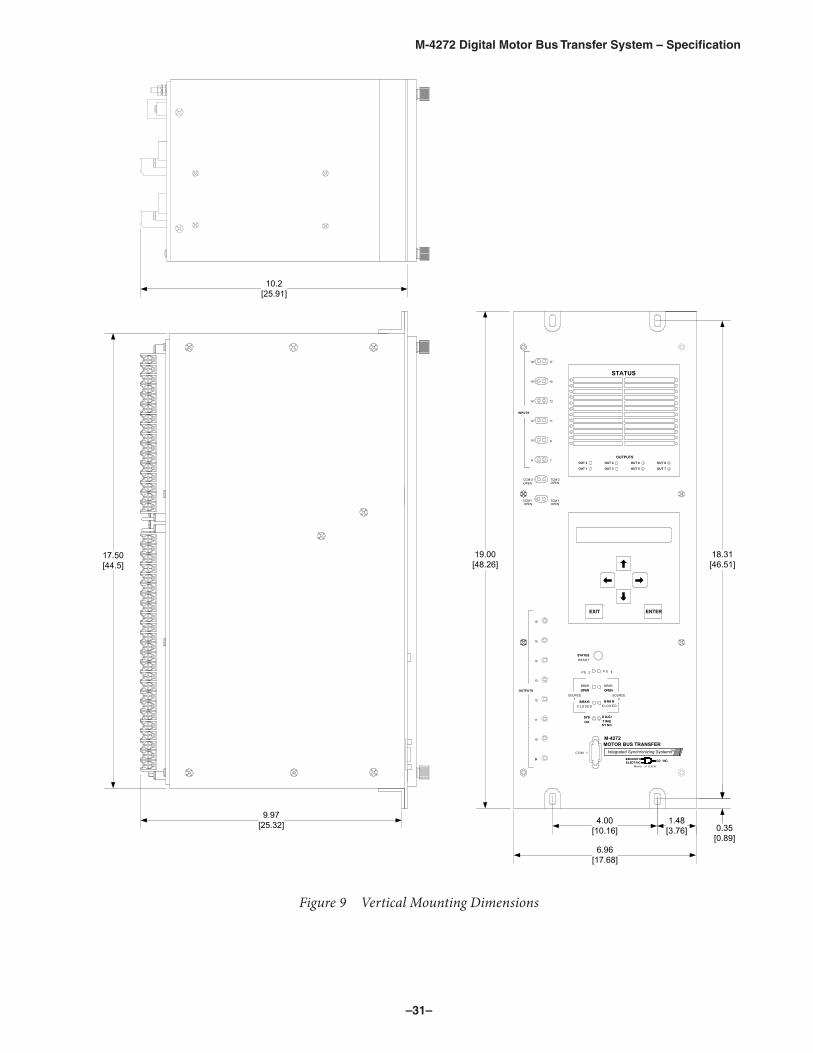
Figure 8 Horizontal Mounting Dimensions
–31–
M‑4272 Digital Motor Bus Transfer System – Specification
ENTEREXIT
STATUS
BRKROPEN
C LO S EDB RK R
C LO S EDB RK R
RES ETSTATUS
PS 2
SOURCE1
1
BRKROPEN
SOURCE2
12
14
16
11
13
15
1718
99
OUTPUTS
10
11
12
13
14
15
16
OPEN
B RK R B RK R
STATUS
S 1
OPEN
INPUTS
C O M 1
TCM-1OPEN
TCM-2OPENOPEN
CCM-1OPEN
910
78
P
OUT 7
OUT 8
OUTPUTS
OUT 5
OUT 6
OUT 3
OUT 4
OUT 1
OUT 2
M-4272
TMIntegrated Synchronizing SystemsITRI
HCE
CEL
KC
WTE
BCKB
ELEC
EMa de in U.S .A .TW
CH
IRTI C ..O. NI CC NI.O C
T IM EYS NC
AID G /T IM E
YS NC
AID G /
O KSYSO KSYS
CCM-2
MOTOR BUS TRANSFER
10.2[25.91]
9.97[25.32]
19.00[48.26]
17.50[44.5]
18.31[46.51]
4.00[10.16]
1.48[3.76]
6.96[17.68]
0.35[0.89]
NOTE: Dimensions in brackets are in centimeters.
Figure 9 Vertical Mounting Dimensions

–32–
M‑4272 Digital Motor Bus Transfer System – Specification
����
���
����
���
���
����
���
���
�����
����
����
��
����
����
���
����
����
���
����
�����
������
�� ��
� ���
���
��
�����
��� ��
��
����
������
���
����
��� ����
���
���
��� ��
���
���
Figure 10 Panel Mount Cutout Dimensions (Horizontal and Vertical)

–33–
M‑4272 Digital Motor Bus Transfer System – Specification
M‑3919A Graphic Display Unit/Touch Screen Human Machine Interface • Provides a MIMIC Single-Line Diagram of the Motor Bus Transfer System in Two-breaker or Three-
breaker Bus Transfer Configuration
• 16.2 Million Color 1024 x 768 Pixel TFT Display
• 12.1 Inch Touch Screen Human Machine Interface (HMI)
• Includes a separate power supply, nominal 120 Vac (50/60 Hz) or 125 Vdc (250 Vdc optional)
• Remote Target Reset Capability
• Remote Manual Transfer Capability
Figure 11 Graphic Display Unit/Touch Screen Human Machine Interface

–34–
M‑4272 Digital Motor Bus Transfer System – Specification
FeaturesThe M-3919A includes the following features and functions:
• Display & Touch Screen
12.1" TFT 16.2 Million colors
Size – 9.75" x 7.25" [248 mm x 184 mm], 12.1" diagonal
Brightness – 500 cd/m2
Contrast Ratio – 700:1
Resolution – 1024 x 768 pixels
Backlight – LED up to 50,000 hour life span
Touch Screen Type – 4-wire Analog Resistive
• Microprocessor – 800 MHz 32-bit CISC (Fanless CPU)
• Flash Memory – 256 MB
• DRAM – 256 MB
• Material – Aluminum Enclosure
• Serial Ports
The M-3919A includes two serial ports, which provide the connections to one or two M-4272 Digital Motor Bus Transfer Systems using RS-232 (standard) or RS-485 (optional) communications. The RS-485 serial port also provides the ability to connect multiple M-4272's in series to a single HMI. The M-3919A serial communication ports include the following capabilities:
One RS-485 serial port (DE9S) used for RS-485 M-4272 communications
One RS-232 serial port (DE9P) used for RS-232 M-4272 communications
Baud rates from 9,600 to 115,200
Point-to-point serial communications for all protocols
• One 10 foot RS-232 Y Cable, BECO Part Number B-1527
• Compact SD Card Slot
• USB Ports – 1 Host 2.0 Port, 1 Client 2.0 Port
• Ethernet Port – 10/100 Base-T (RJ45) used for Operator Interface Terminal (OIT) (PC) configuration, downloading program to HMI and Point-to-Point connection and communications using MODBUS TCP/IP.
• PWR (yellow) illuminated icon indicates if power is applied to the unit
• CPU (green) illuminated icon indicates if the unit is operating correctly
• COM (red) illuminated icon indicates communications activity on PLC port
• RESET Switch to reinitialize the unit if an operational failure occurs
–35–
M‑4272 Digital Motor Bus Transfer System – Specification
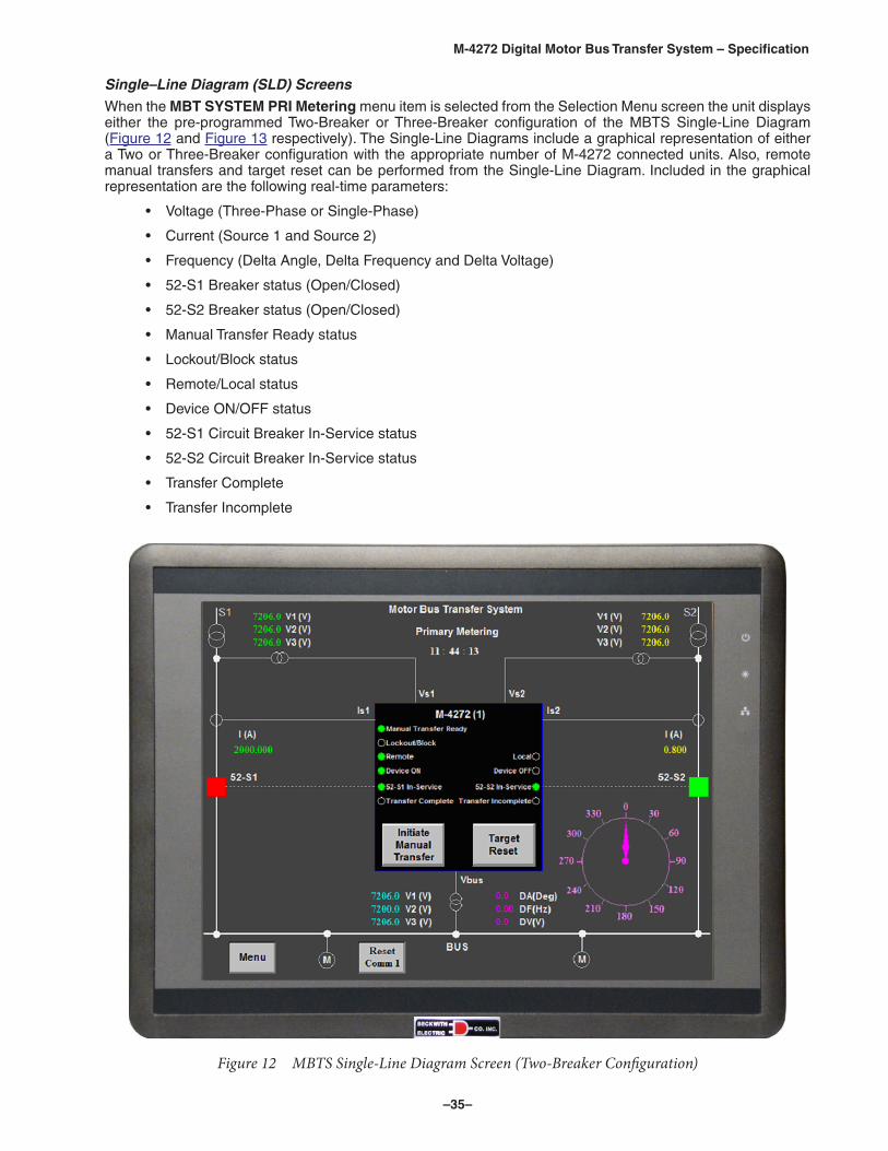
Single–Line Diagram (SLD) Screens
When the MBT SYSTEM PRI Metering menu item is selected from the Selection Menu screen the unit displays either the pre-programmed Two-Breaker or Three-Breaker configuration of the MBTS Single-Line Diagram (Figure 12 and Figure 13 respectively). The Single-Line Diagrams include a graphical representation of either a Two or Three-Breaker configuration with the appropriate number of M-4272 connected units. Also, remote manual transfers and target reset can be performed from the Single-Line Diagram. Included in the graphical representation are the following real-time parameters:
• Voltage (Three-Phase or Single-Phase)
• Current (Source 1 and Source 2)
• Frequency (Delta Angle, Delta Frequency and Delta Voltage)
• 52-S1 Breaker status (Open/Closed)
• 52-S2 Breaker status (Open/Closed)
• Manual Transfer Ready status
• Lockout/Block status
• Remote/Local status
• Device ON/OFF status
• 52-S1 Circuit Breaker In-Service status
• 52-S2 Circuit Breaker In-Service status
• Transfer Complete
• Transfer Incomplete
Figure 12 MBTS Single-Line Diagram Screen (Two-Breaker Configuration)

–36–
M‑4272 Digital Motor Bus Transfer System – Specification
Figure 13 MBTS Single-Line Diagram Screen (Three-Breaker Configuration)
Initiating Manual Transfers
The GDU/HMI includes the capability to initiate Manual Transfers from the Single-Line diagram.
See M-3919A Specification for additional details.
Optional Features • 250 Vdc Power Supply, BECO Part Number 430-00444
• Two-Breaker or Three-Breaker configuration
• RS-485 Communication with one 10 foot RS-485 Y-Cable, BECO Part Number B-1301
• 19" Mounting Panel, 7u height, BECO Part Number 441-41959
PhysicalSize: 12.49" wide x 9.61" high x 1.82" deep (31.7 cm x 24.4 cm x 4.6 cm)
Approximate Weight: 4.6 lbs (2.1 kg)
WarrantyThe M-3919A is covered by a two-year warranty from date of shipment.
Specification subject to change without notice.

–37–
M‑4272 Digital Motor Bus Transfer System – Specification
M‑5072 Retrofit Kit For M‑4272 Digital Motor Bus Transfer System • Adapts M-4272 Digital Motor Bus Transfer System as a replacement for existing analog motor bus
transfer equipment
• Provides direct mechanical and electrical replacement of existing analog transfer logic controller M-0272/M-0236B
• Connects easily to the M-4272's terminals without any wiring change
• The physical change is simple and cost effective
• Enhances the security, reliability and performance of your facility with additional features in the digital motor bus transfer equipment
• Optional M-3919A Graphic Display Unit (GDU) and Touch Screen Human Machine Interface (HMI) for communicating with one or two M-4272 units.
M‑5072 Retrofit Kit FeaturesThe M-4272 Digital Motor Bus Transfer System and a M-5072 retrofit kit provide the direct replacement of the M-0272/M-0236B Analog Transfer Logic Controller. The physical change is very simple and cost effective.
The M-5072 retrofit kit consists of a bracket and wiring harness (Figure 14) that replicates the existing M-0272 terminal block locations. The M-5072 terminal blocks are located in the same positions (Figure 15) as the M-0272 and it is attached to the M-4272. The wire harness connects the appropriate terminals between the M-4272 and the M-0272. This will allow a very simple replacement of the existing M-0272 equipment.
Since the existing analog M-0272/M-0236B takes 7u height while the M-4272 takes only 4u height. One rack mount black blank panel with 1u height and one rack mount black blank panel with 2u height are provided to fill up the empty spaces after the replacement.
Figure 14 M-5072 Retrofit Kit for Analog Motor Bus Transfer System Replacement

–38–
M‑4272 Digital Motor Bus Transfer System – Specification
Dan
ger!
Con
tact
ave
c le
s te
rmin
aux
peut
cau
ser u
n ch
oc e
lect
rique
Figure 15 M-5072 Retrofit Kit Bracket and Wiring Harness

–39–
M‑4272 Digital Motor Bus Transfer System – Specification
PhysicalM-5072Size: 8.37" high x 17.25" wide x 3.89" deep (21.26 x 43.82 x 9.88)
Approximate Weight: 3 lbs (1.4 kg)
Approximate Shipping Weight: 5 lbs (2.3 kg)
M-5072 with M-4272Size: 8.37" high x 19" wide x 12.86" deep (21.26 x 48.26 x 32.66)
Approximate Weight: 23 lbs (10.5 kg)
Approximate Shipping Weight: 35 lbs (15.9 kg)
WarrantyThe M-5072 is covered by a five-year warranty from date of shipment. The M-3919A is covered by a two-year warranty from date of shipment.
TRADEMARKSAll brand or product names referenced in this document may be trademarks or registered trademarks of their respective holders.
Specification subject to change without notice. Beckwith Electric Co., Inc. has approved only the English version of this document.

BECKWITH ELECTRIC CO., INC.6190 - 118th Avenue North • Largo, Florida 33773-3724 U.S.A.
PHONE (727) 544-2326 • FAX (727) [email protected]
www.beckwithelectric.comISO 9001:2008
800-4272-SP-11 01/18© 2004 Beckwith Electric Co. All Rights Reserved.Printed in U.S.A. (2.07.03)
Recommended