ELECTRO HYDROSTATIC ACTUATORS
A NEW APROACH IN MOTION CONTROL
2nd Workshop on Innovative Engineering for Fluid PowerSep 2-3 2014
2
Agenda
• Introduction - MOOG
• Actuation Technologies
• Electro Hydrostatic Actuators
• Applications
3
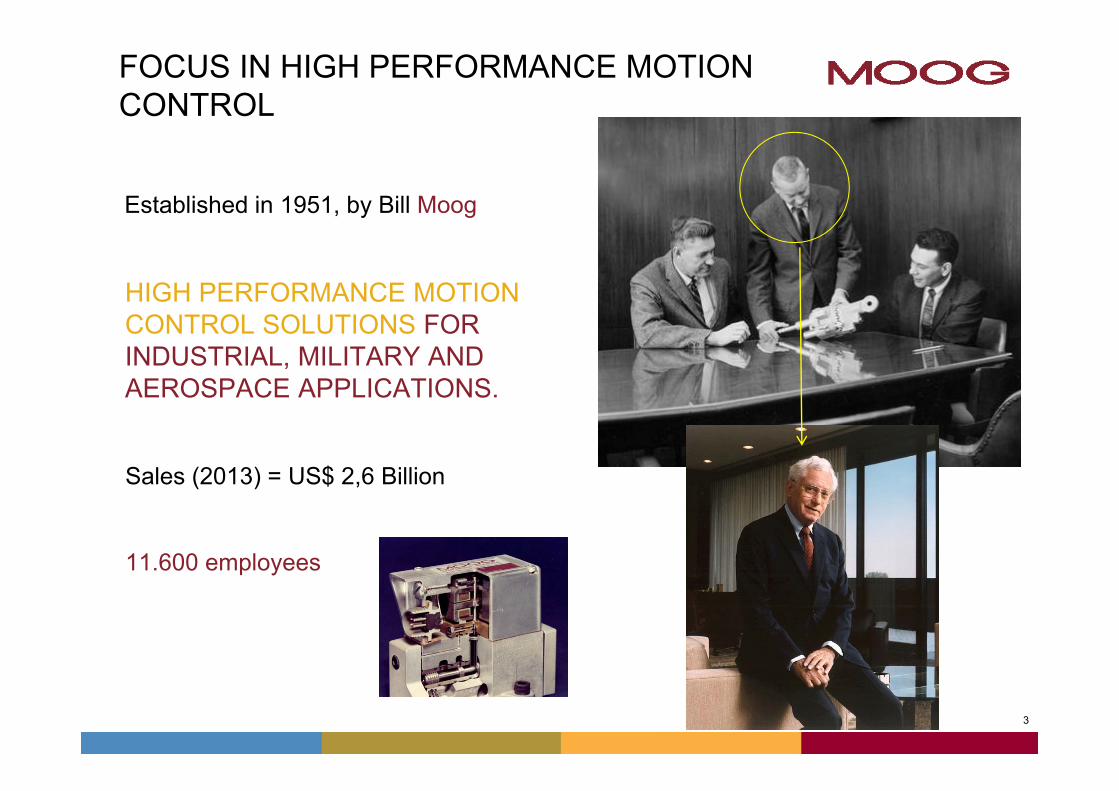
Established in 1951, by Bill Moog
HIGH PERFORMANCE MOTION CONTROL SOLUTIONS FOR INDUSTRIAL, MILITARY AND AEROSPACE APPLICATIONS.
Sales (2013) = US$ 2,6 Billion
11.600 employees
FOCUS IN HIGH PERFORMANCE MOTION CONTROL
4
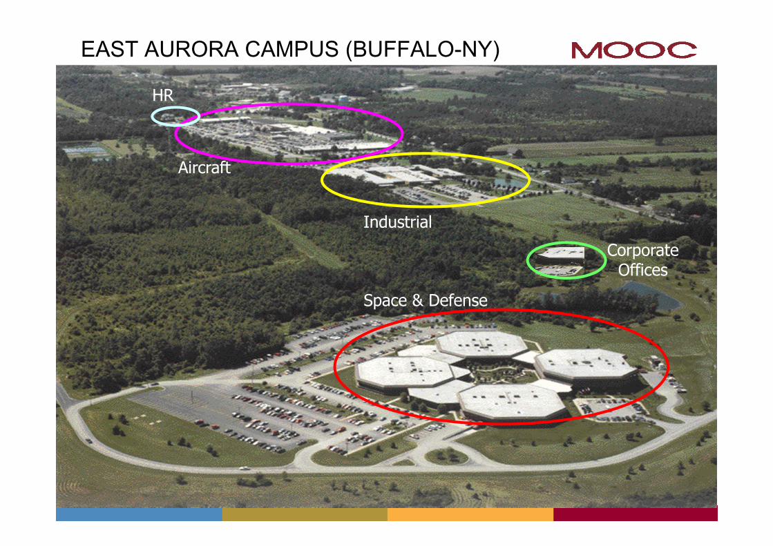
EAST AURORA CAMPUS (BUFFALO-NY)
4
Space & Defense
Industrial
Aircraft
CorporateOffices
HR
5
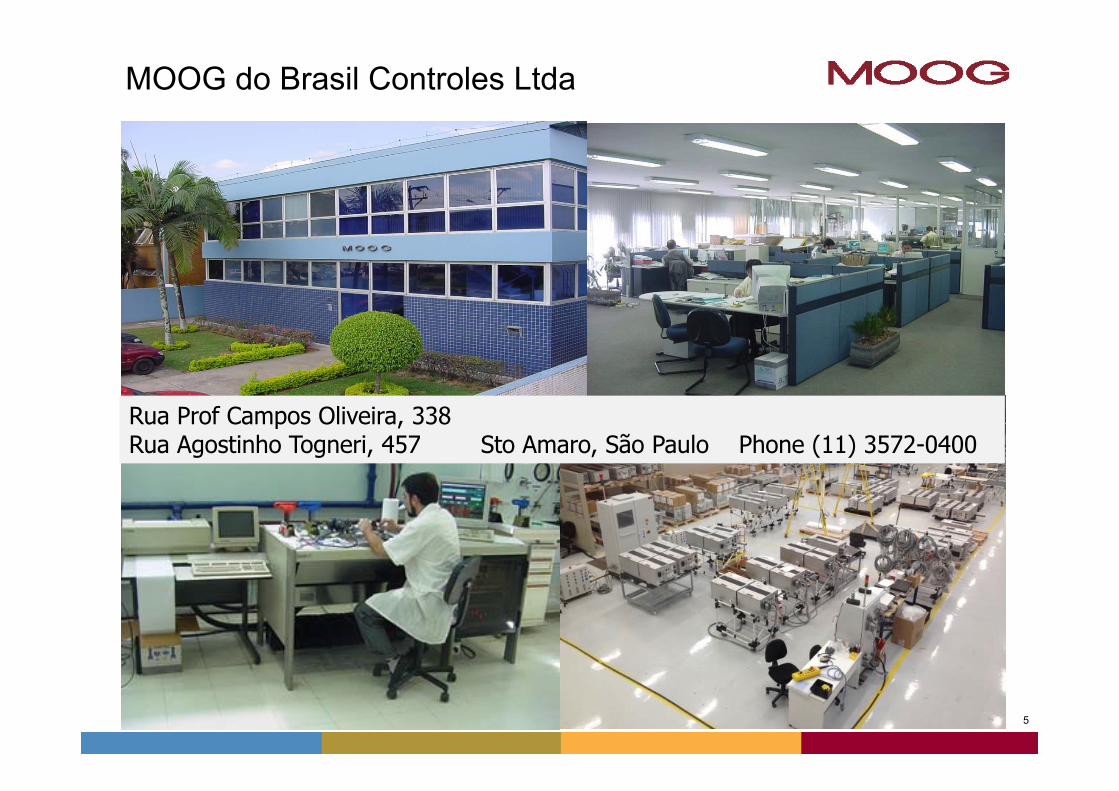
MOOG do Brasil Controles Ltda
Rua Prof Campos Oliveira, 338 Rua Agostinho Togneri, 457 Sto Amaro, São Paulo Phone (11) 3572-0400
6
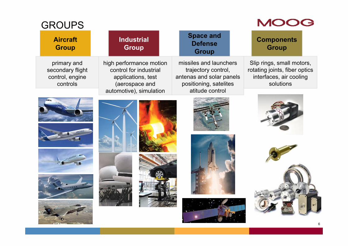
GROUPS
missiles and launchers trajectory control,
antenas and solar panels positioning, satelites
atitude control
Space and Defense Group
Slip rings, small motors, rotating joints, fiber optics
interfaces, air cooling solutions
Components Group
high performance motion control for industrial
applications, test (aerospace and
automotive), simulation
Industrial Group
primary and secondary flight control, engine
controls
Aircraft Group
7
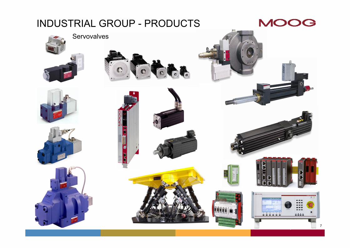
INDUSTRIAL GROUP - PRODUCTS
7
Servovalves
8
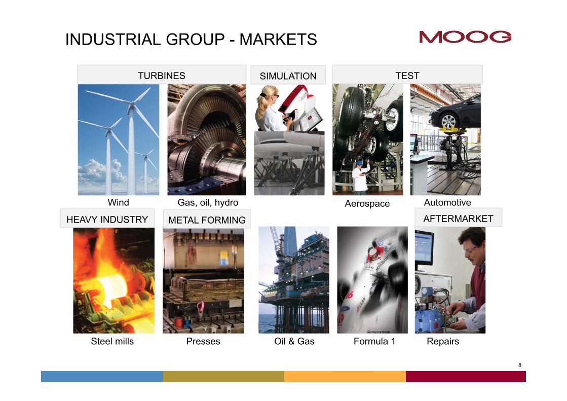
INDUSTRIAL GROUP - MARKETS
8
TURBINES
Wind Gas, oil, hydro Automotive
SIMULATION TEST
Aerospace
Steel mills Presses RepairsOil & Gas
AFTERMARKETHEAVY INDUSTRY METAL FORMING
Formula 1
9
Agenda
• Introduction - MOOGA
• Actuation Technologies
• Electro Hydrostatic Actuators
• Applications
9
1010
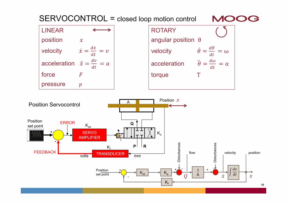
SERVOCONTROL = closed loop motion controlLINEARposition
velocity
acceleration
force pressure
ROTARYangular position θ
velocity ω
acceleration α
torque T
Position Servocontrol
Kq1A
Positionset point
++ + --
-Ksa
KfD
istu
rban
ces
velocity position
Dis
turb
ance
s
flowTRANSDUCER
ERROR
mmvoltsFEEDBACK
+
-
Position
Q
P R
SERVOAMPLIFIER
Positionset point
Kq
Ksa
Kf
A
11
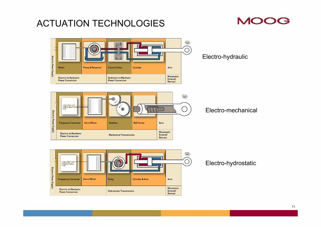
ACTUATION TECHNOLOGIES
Electro-mechanical
Electro-hydraulic
Electro-hydrostatic
12
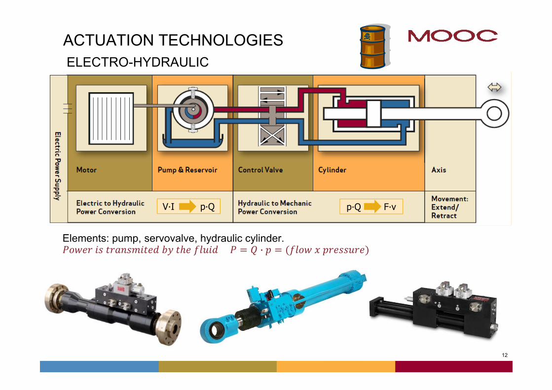
ACTUATION TECHNOLOGIES
Conversão de Potencia Elétrica (V∙I) em Potencia Hidráulica (P∙Q)
ELECTRO-HYDRAULIC
V∙I p∙Q p∙Q F∙v
Elements: pump, servovalve, hydraulic cylinder. ·
13
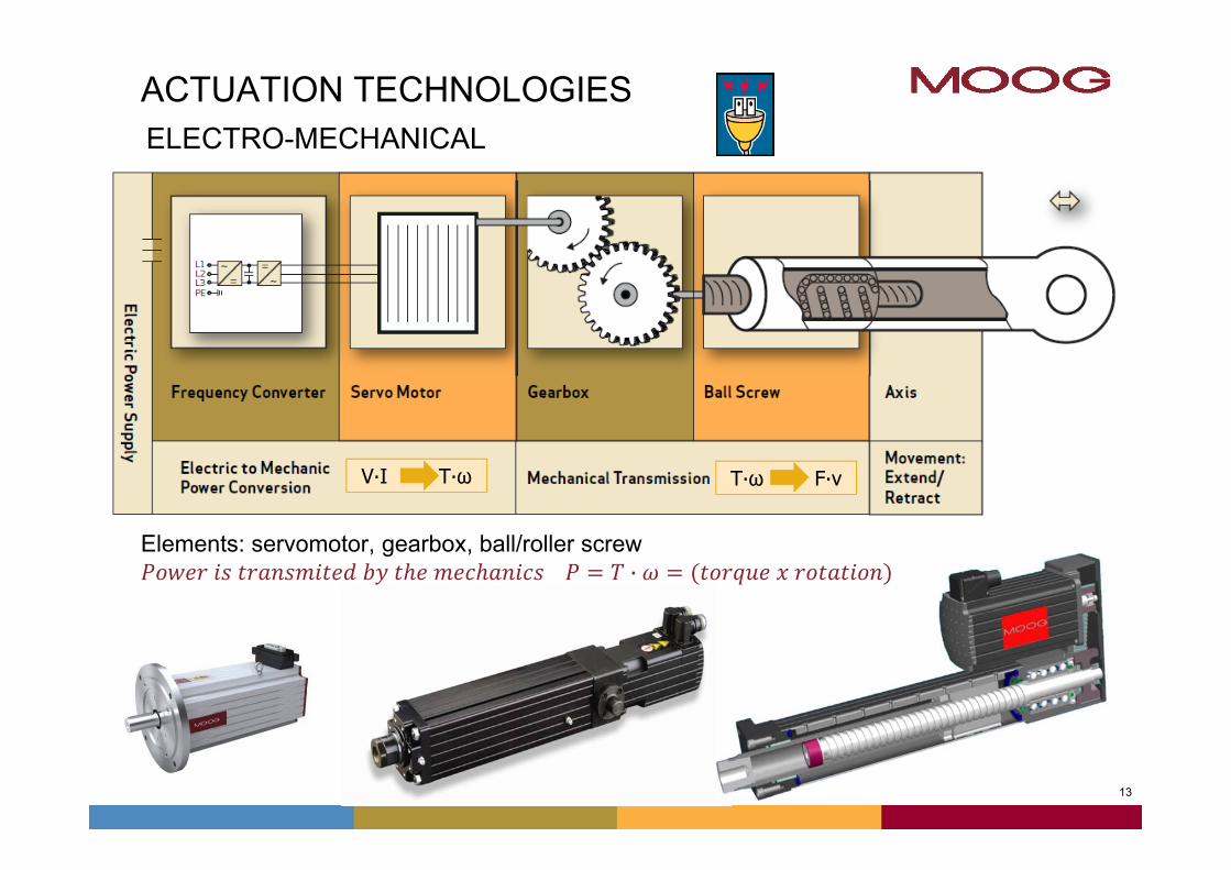
ACTUATION TECHNOLOGIESELECTRO-MECHANICAL
T∙ω F∙vV∙I T∙ω
Elements: servomotor, gearbox, ball/roller screw ·
14
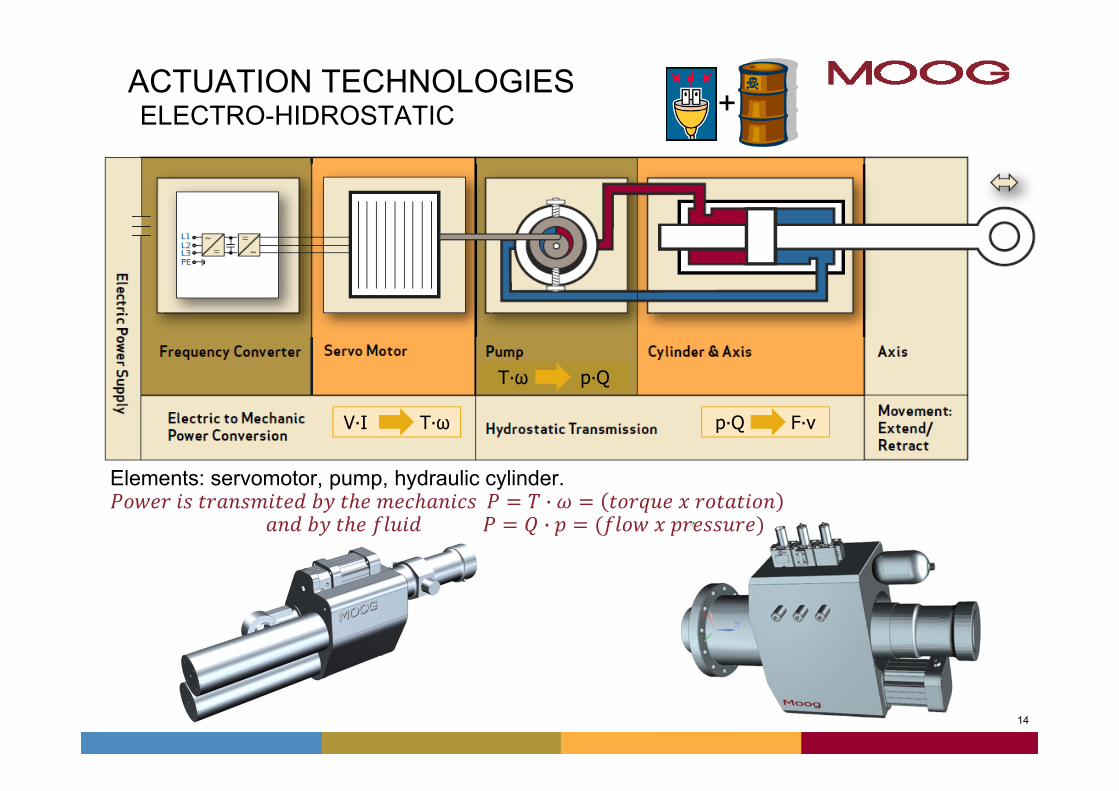
ACTUATION TECHNOLOGIESELECTRO-HIDROSTATIC
T∙ω p∙Q
p∙Q F∙vV∙I T∙ω
Elements: servomotor, pump, hydraulic cylinder. ·
·
+
15
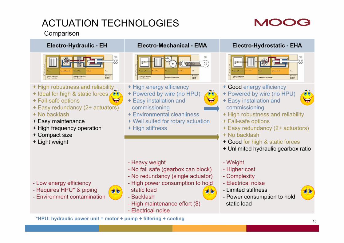
ACTUATION TECHNOLOGIESComparison
Electro-Hydraulic - EH Electro-Mechanical - EMA Electro-Hydrostatic - EHA
+ High robustness and reliability+ Ideal for high & static forces+ Fail-safe options + Easy redundancy (2+ actuators)+ No backlash+ Easy maintenance+ High frequency operation+ Compact size + Light weight
- Low energy efficiency- Requires HPU* & piping- Environment contamination
+ High energy efficiency+ Powered by wire (no HPU)+ Easy installation and
commissioning+ Environmental cleanliness + Well suited for rotary actuation+ High stiffness
- Heavy weight- No fail safe (gearbox can block)- No redundancy (single actuator)- High power consumption to holdstatic load
- Backlash- High maintenance effort ($)- Electrical noise
+ Good energy efficiency+ Powered by wire (no HPU)+ Easy installation and
commissioning+ High robustness and reliability+ Fail-safe options + Easy redundancy (2+ actuators)+ No backlash+ Good for high & static forces+ Unlimited hydraulic gearbox ratio
- Weight- Higher cost- Complexity - Electrical noise- Limited stiffness- Power consumption to holdstatic load
*HPU: hydraulic power unit = motor + pump + filtering + cooling
16
Agenda
• Introduction - MOOG
• Actuation Technologies
• Electro Hydrostatic Actuators
• Applications
17
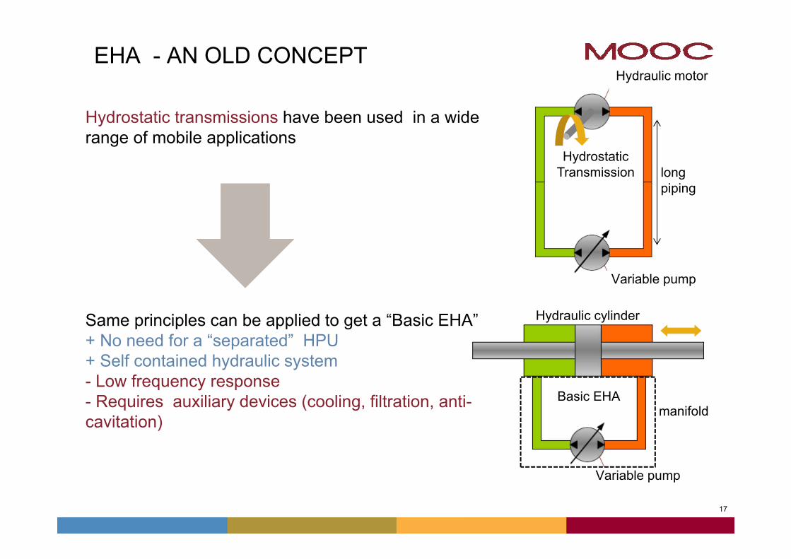
EHA - AN OLD CONCEPT
Hydrostatic transmissions have been used in a wide range of mobile applications
Same principles can be applied to get a “Basic EHA”+ No need for a “separated” HPU+ Self contained hydraulic system- Low frequency response- Requires auxiliary devices (cooling, filtration, anti-cavitation)
Basic EHA
Hydrostatic Transmission
Variable pump
Hydraulic motor
Variable pump
longpiping
manifold
Hydraulic cylinder
1818
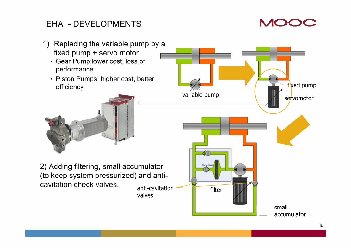
EHA - DEVELOPMENTS
1) Replacing the variable pump by a fixed pump + servo motor• Gear Pump:lower cost, loss of
performance• Piston Pumps: higher cost, better
efficiency
2) Adding filtering, small accumulator(to keep system pressurized) and anti-cavitation check valves.
variable pump servomotor
fixed pump
filteranti-cavitationvalves
smallaccumulator
19
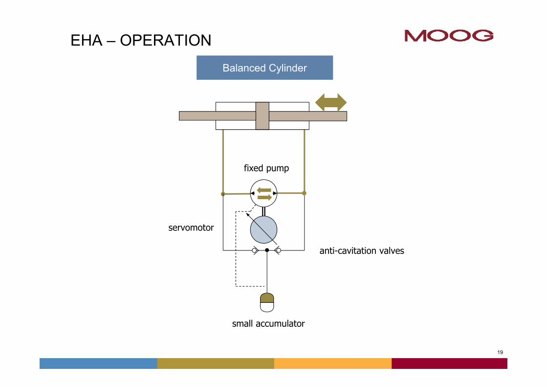
EHA – OPERATION
vv
Balanced Cylinder
anti-cavitation valves
small accumulator
fixed pump
servomotor
20
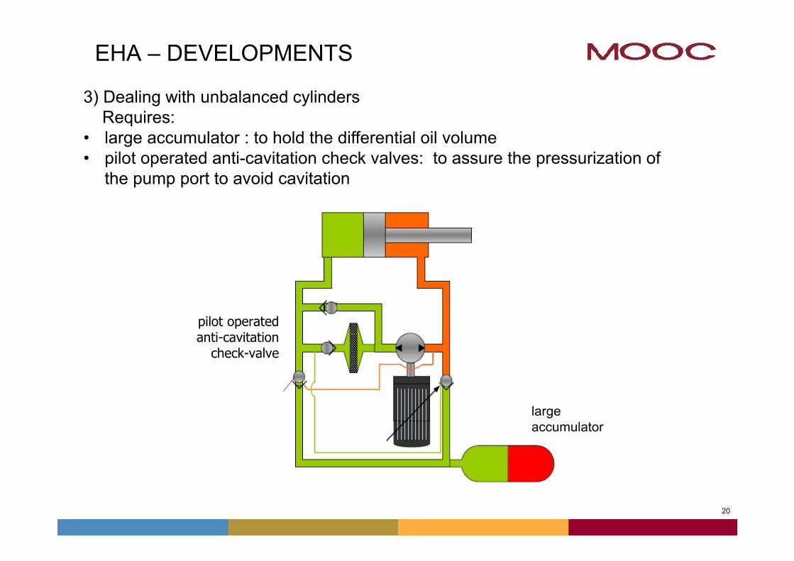
EHA – DEVELOPMENTS
pilot operatedanti-cavitation
check-valve
large accumulator
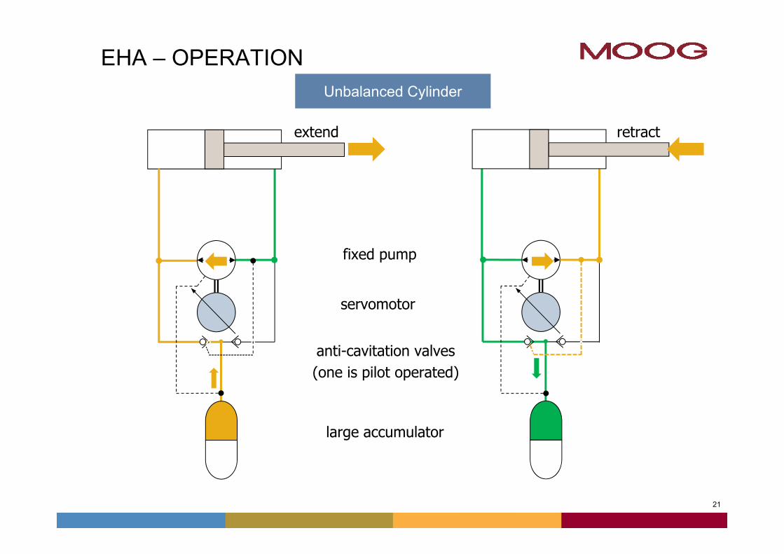
3) Dealing with unbalanced cylindersRequires:
• large accumulator : to hold the differential oil volume• pilot operated anti-cavitation check valves: to assure the pressurization of
the pump port to avoid cavitation
21
v
EHA – OPERATION
v
v
Unbalanced Cylinder
v
v v
v
v
servomotor
fixed pump
large accumulator
anti-cavitation valves(one is pilot operated)
extend retract
22
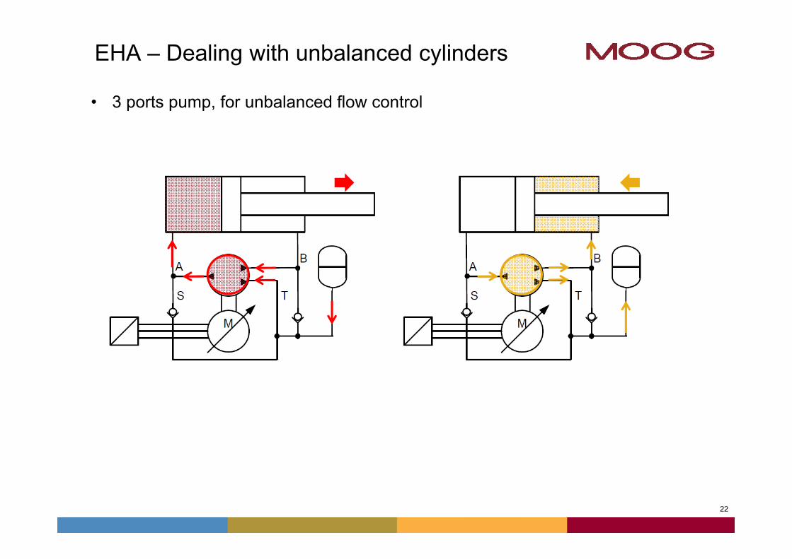
EHA – Dealing with unbalanced cylinders
• 3 ports pump, for unbalanced flow control
23
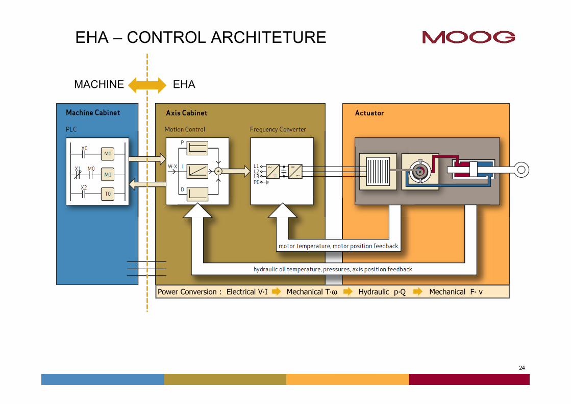
EHA – CONTROL ARCHITETURE
M
TemposonicsTemposonics
Comando de Posição
Real
imen
taçã
o
Servomotor
Transdutor de Posição
Bomba Bidirecional
Position Transducer
Bidirectional pump
Servomotor
Position Command
Posi
tion
Feed
back
Hydraulic Cylinder
24
EHA – CONTROL ARCHITETURE
Power Conversion : Electrical V∙I Mechanical T∙ω Hydraulic p∙Q Mechanical F∙ v
MACHINE EHA
25
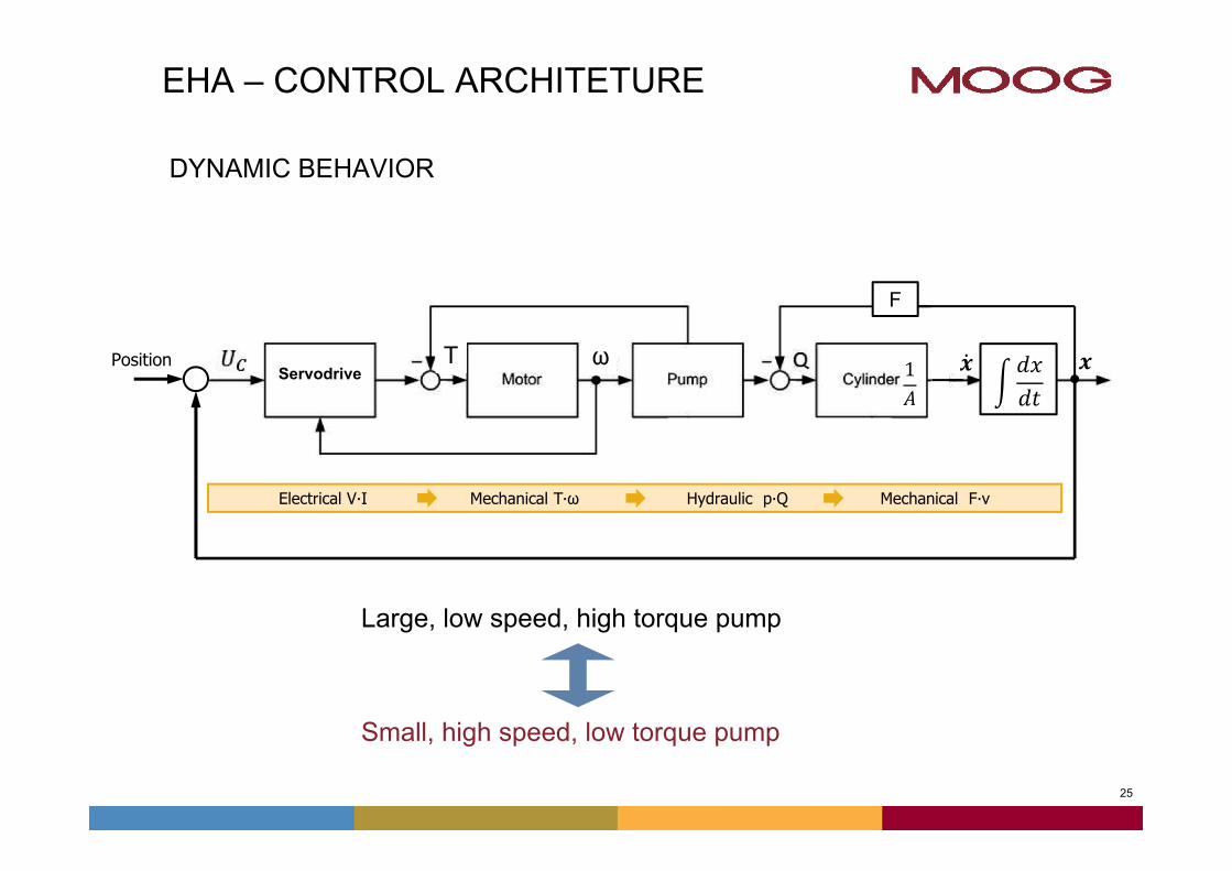
EHA – CONTROL ARCHITETURE
Electrical V∙I Mechanical T∙ω Hydraulic p∙Q Mechanical F∙v
DYNAMIC BEHAVIOR
ωT 1PositionServodrive
F
Large, low speed, high torque pump
Small, high speed, low torque pump
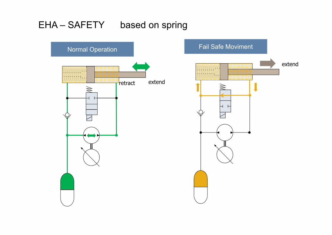
EHA – SAFETY based on spring
Fail Safe MovimentNormal Operation
v
extend
extendretract
27
v
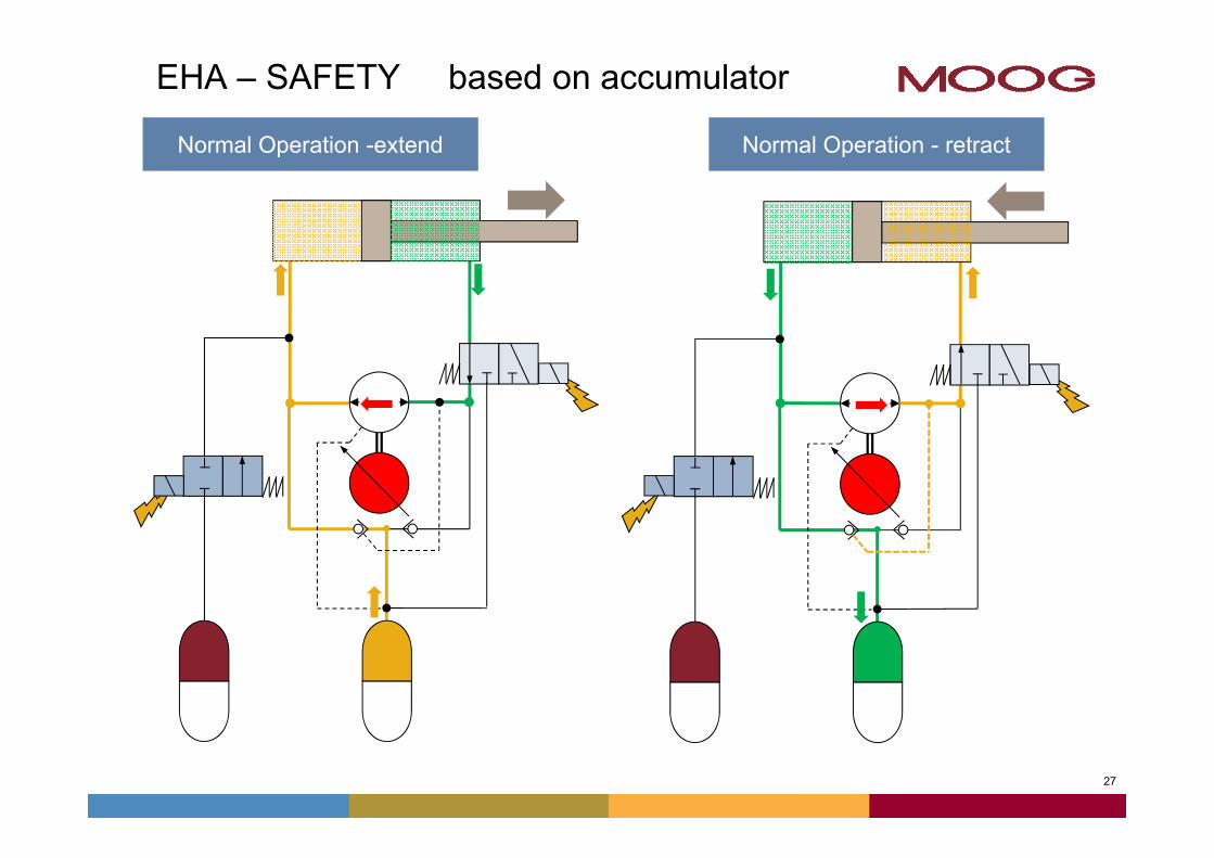
EHA – SAFETY based on accumulator
Normal Operation -extend
v
Normal Operation - retract
28
v
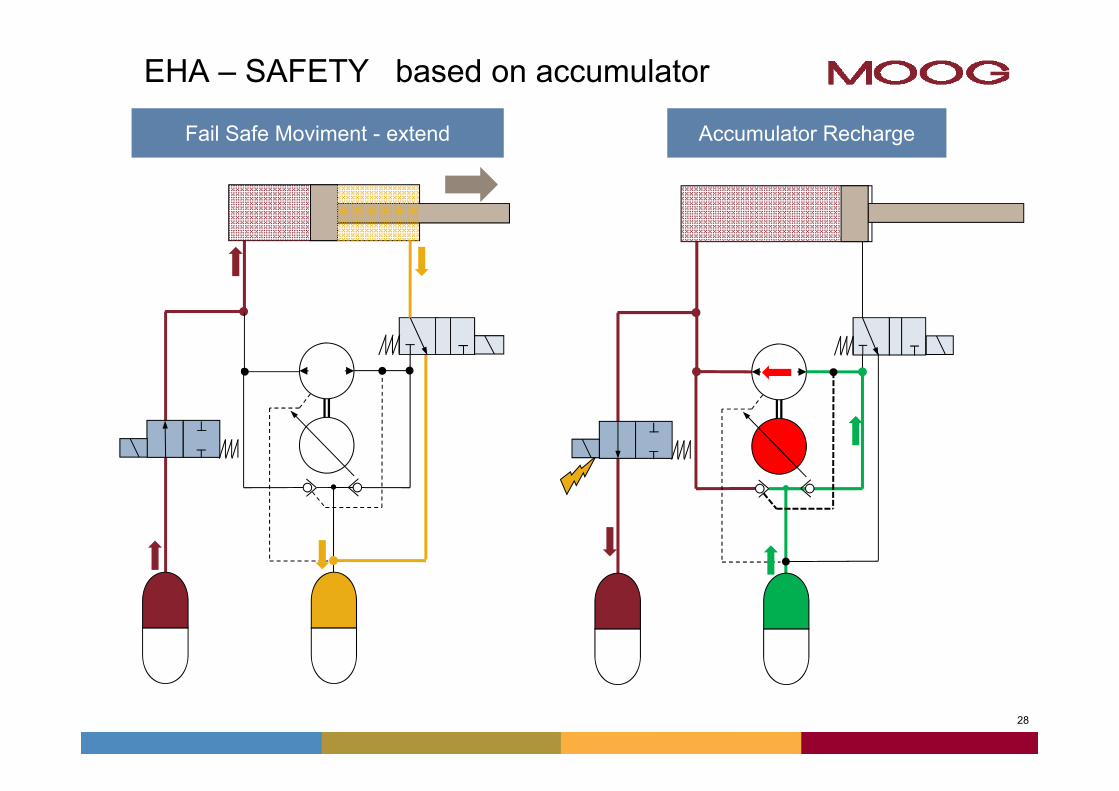
EHA – SAFETY based on accumulator
Fail Safe Moviment - extend
v
Accumulator Recharge
29
Agenda
• Introduction - MOOG
• Actuation Technologies
• Electro Hydrostatic Actuators
• Applications
30
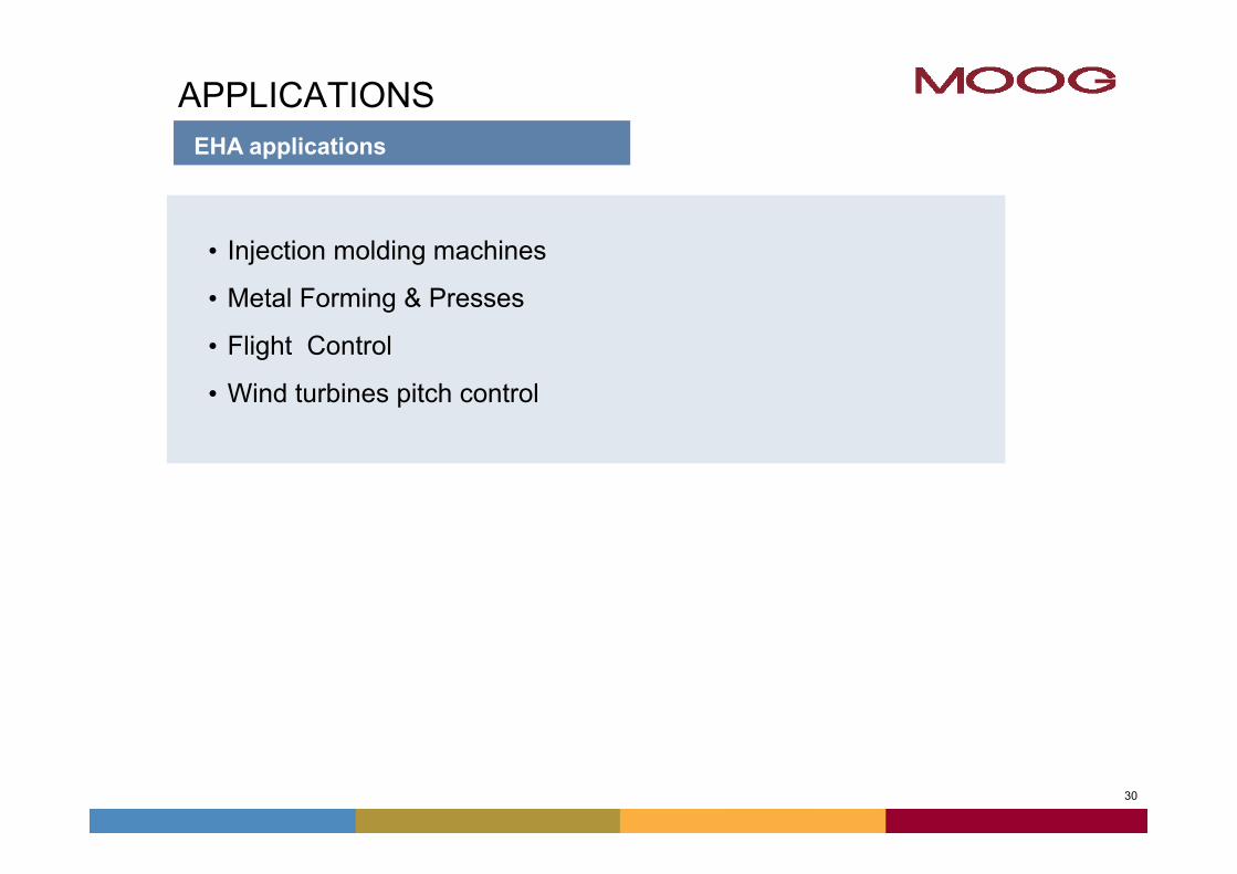
APPLICATIONSEHA applications
• Injection molding machines
• Metal Forming & Presses
• Flight Control
• Wind turbines pitch control
31
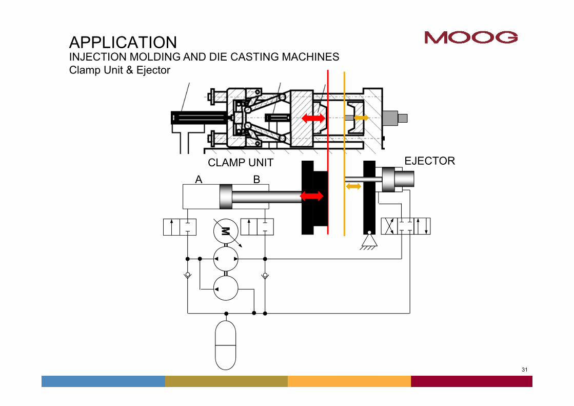
APPLICATION
M
A B
INJECTION MOLDING AND DIE CASTING MACHINES Clamp Unit & Ejector
CLAMP UNIT EJECTOR
32
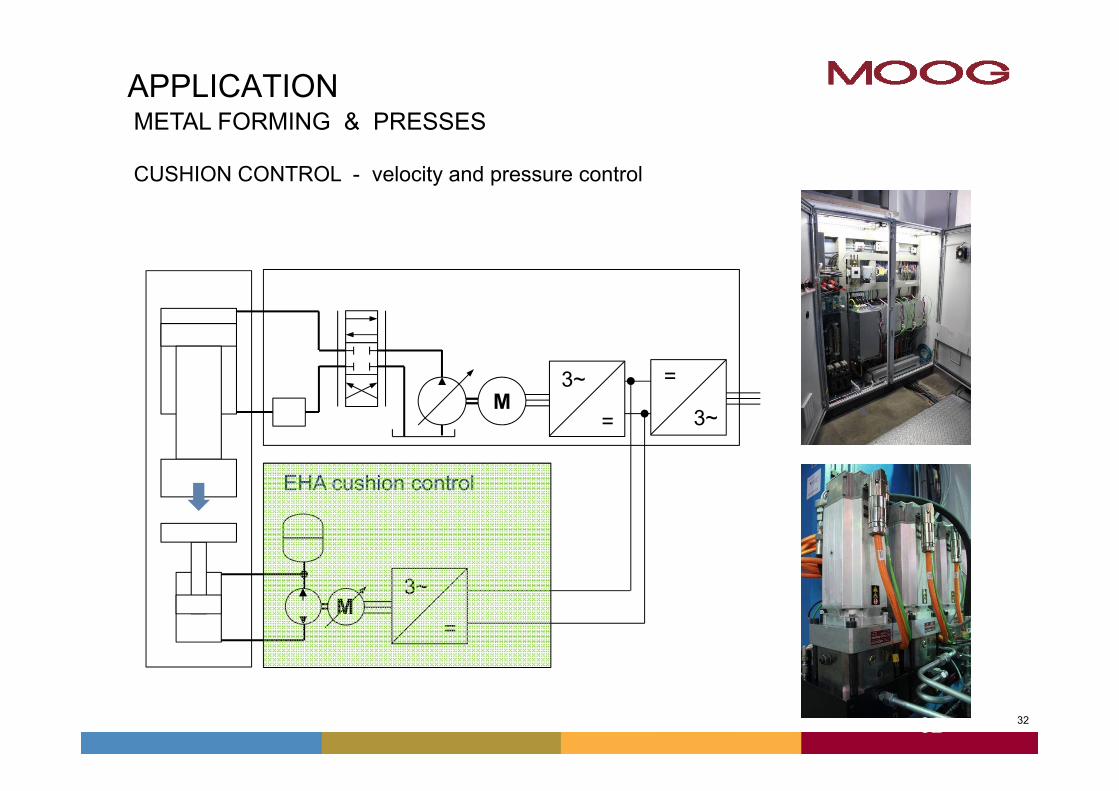
APPLICATION
EHA cushion control
METAL FORMING & PRESSES
CUSHION CONTROL - velocity and pressure control
M
M
3~
=
3~
= 3~
=
32
33
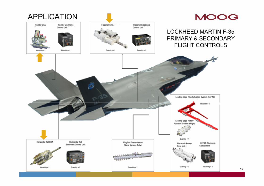
APPLICATION
LOCKHEED MARTIN F-35 PRIMARY & SECONDARY
FLIGHT CONTROLS
34
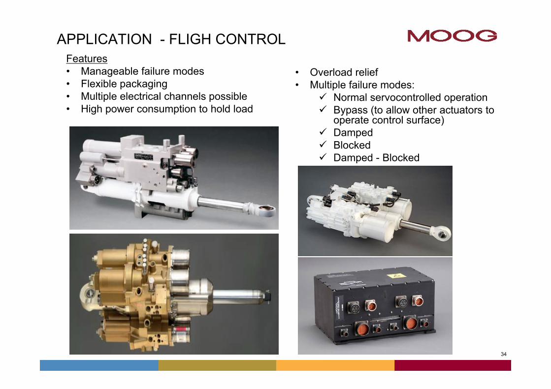
APPLICATION - FLIGH CONTROLFeatures• Manageable failure modes• Flexible packaging• Multiple electrical channels possible• High power consumption to hold load
• Overload relief• Multiple failure modes:
Normal servocontrolled operation Bypass (to allow other actuators to
operate control surface) Damped Blocked Damped - Blocked
35
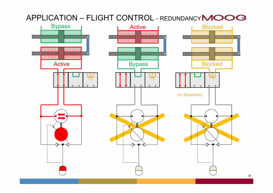
APPLICATION – FLIGHT CONTROL - REDUNDANCY
Active Bypass Blocked
v
v
Bypass Active Blocked
(or dampered)
v v v v
36
vv
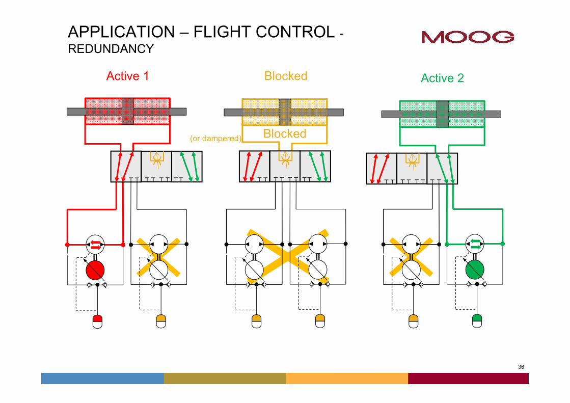
APPLICATION – FLIGHT CONTROL -REDUNDANCY
Active 1
vv
Active 2
Blocked
Blocked
(or dampered)
vv
37
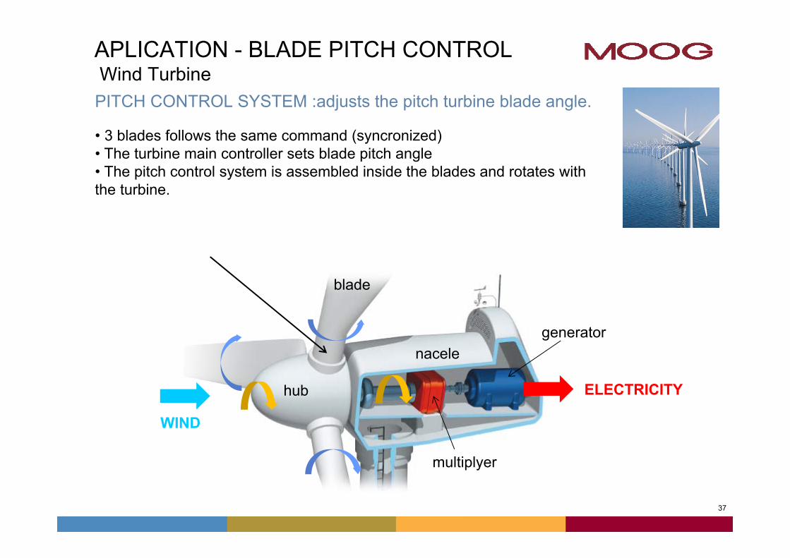
APLICATION - BLADE PITCH CONTROLWind TurbinePITCH CONTROL SYSTEM :adjusts the pitch turbine blade angle.
• 3 blades follows the same command (syncronized)• The turbine main controller sets blade pitch angle• The pitch control system is assembled inside the blades and rotates withthe turbine.
WIND
multiplyer
ELECTRICITY
blade
nacele
hub
torre
generator
38
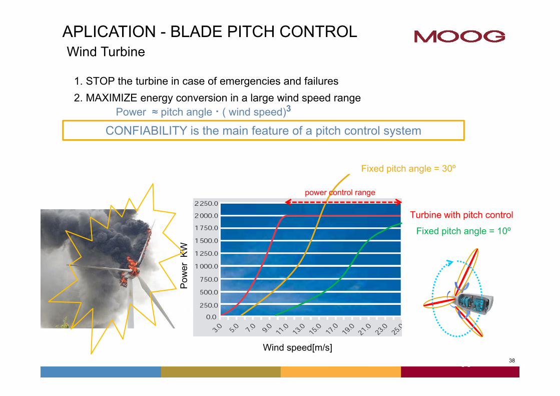
1. STOP the turbine in case of emergencies and failures2. MAXIMIZE energy conversion in a large wind speed range
Power ≈ pitch angle ∙ ( wind speed)3
38
APLICATION - BLADE PITCH CONTROLWind Turbine
Pow
er K
W
Wind speed[m/s]
Turbine with pitch control
Fixed pitch angle = 10º
Fixed pitch angle = 30º
power control range
CONFIABILITY is the main feature of a pitch control system
39
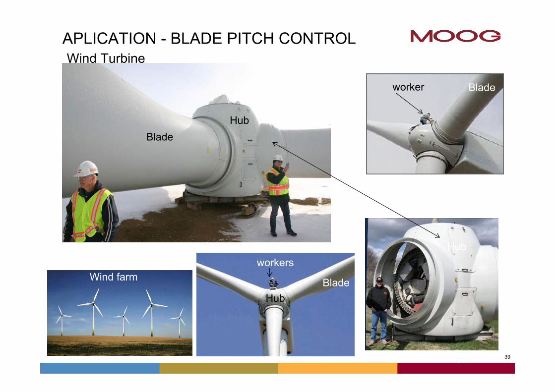
APLICATION - BLADE PITCH CONTROLWind Turbine
39
BladePá
Hub
worker
Hub
workers
Blade
Hub
Wind farm
Blade
40
APLICATION - BLADE PITCH CONTROLWind Turbine
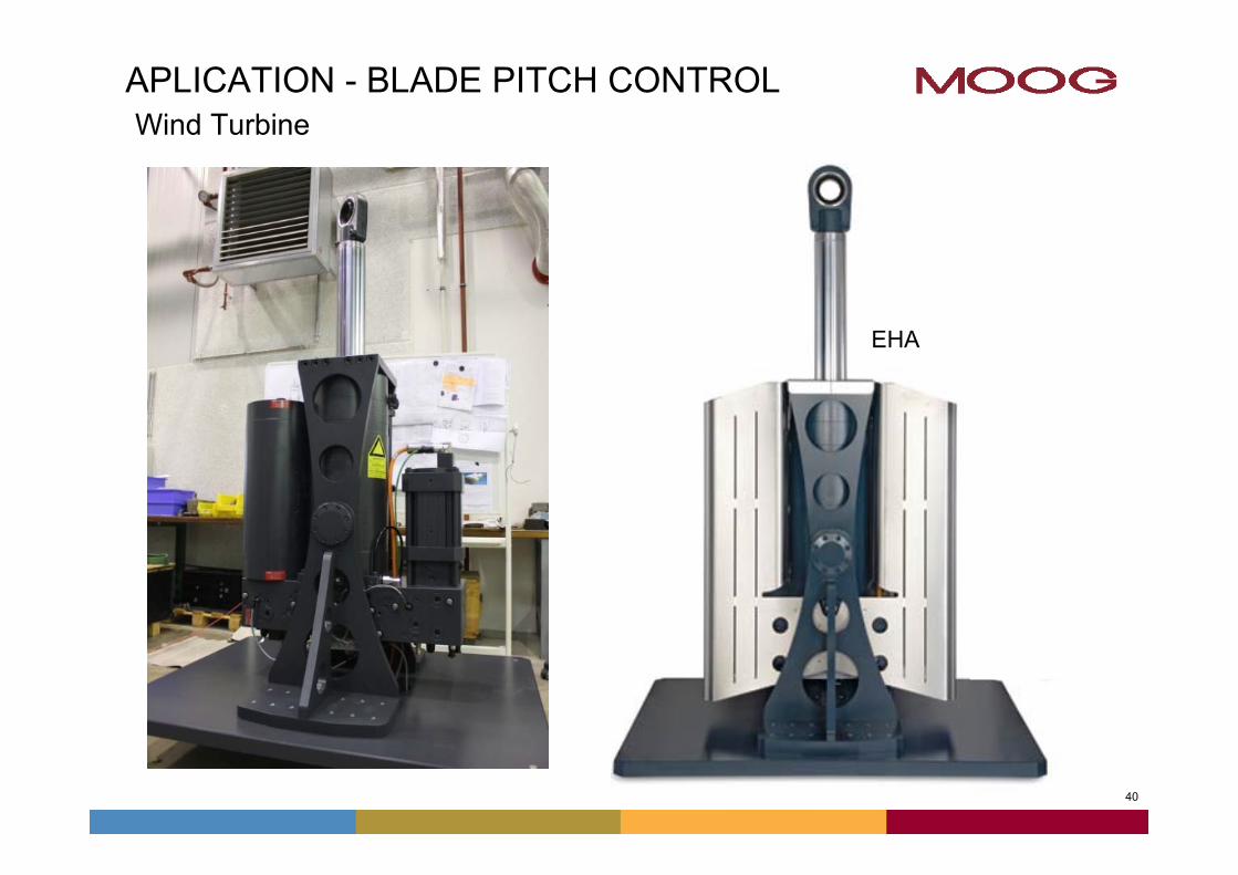
EHA
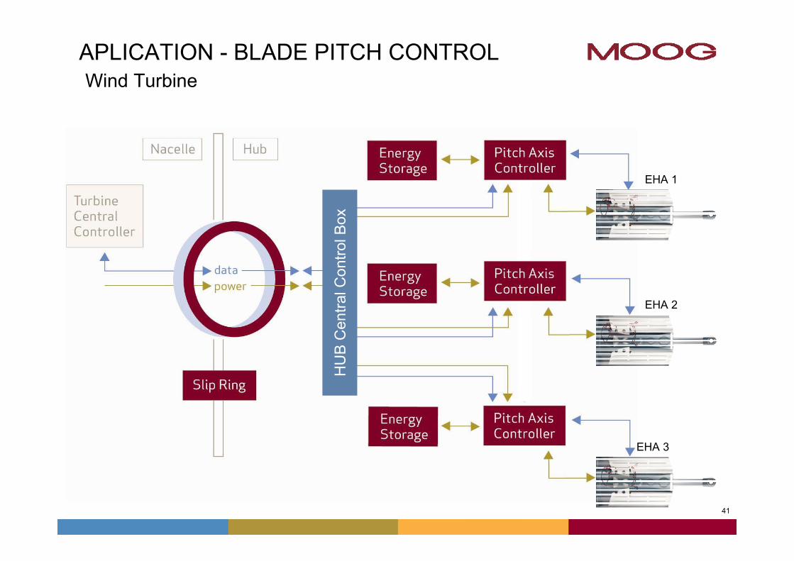
41
APLICATION - BLADE PITCH CONTROLWind Turbine
HU
B C
entra
l Con
trolB
ox
EHA 1
EHA 2
EHA 3
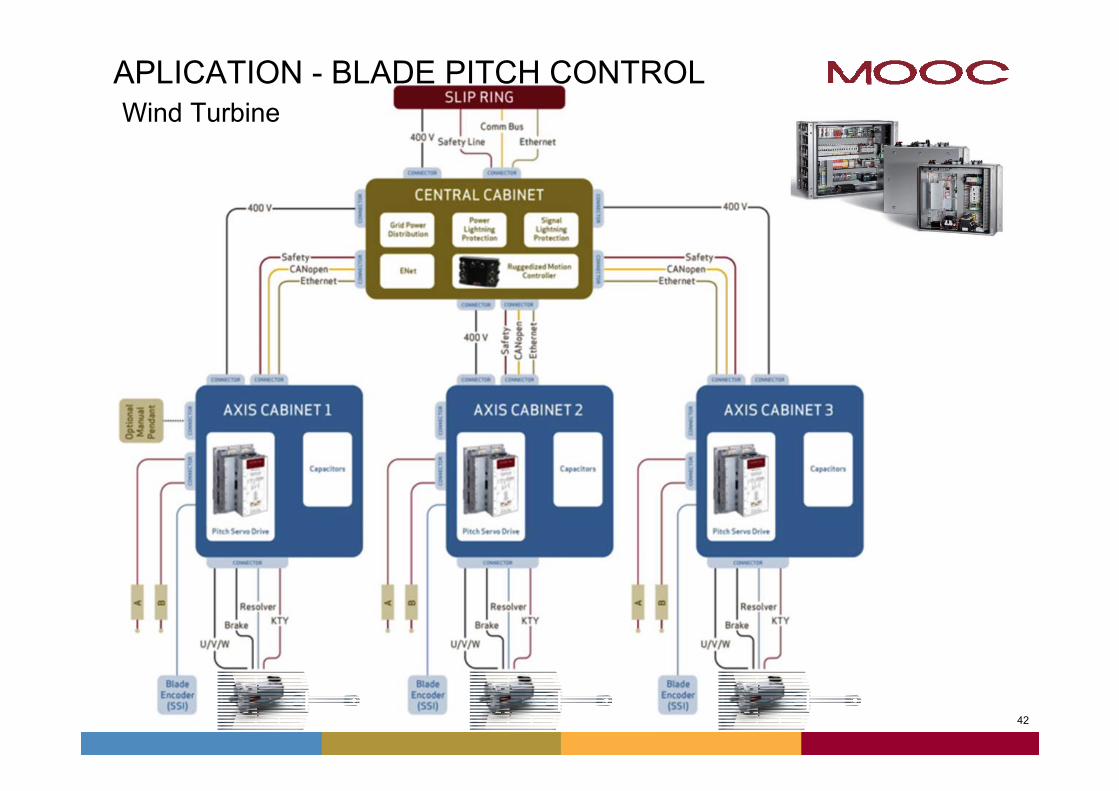
42
APLICATION - BLADE PITCH CONTROLWind Turbine

43
That’s all folks!
For additional info, please contact : Mario [email protected]: +55 (11) 3572-0404
MOOG do Brasil Controles LtdaRua Prof Campos de Oliveira, 33804675-100 São Paulo –SPPhone :+55 (11) [email protected]
43
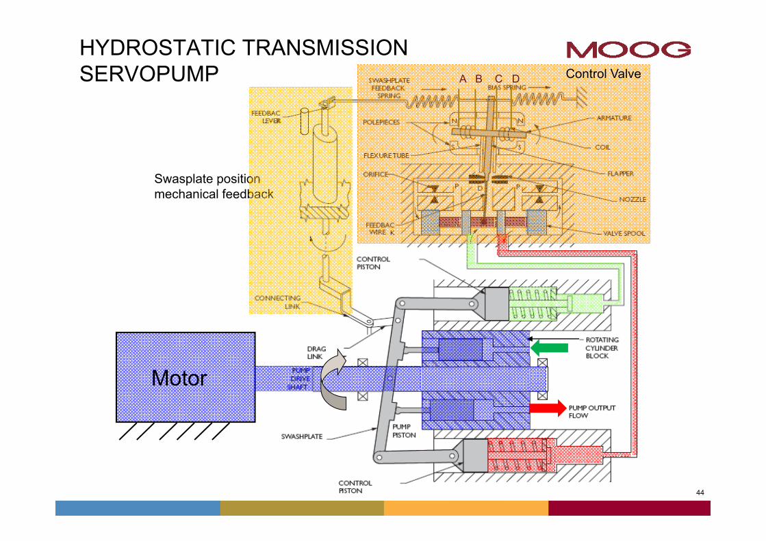
44
Motor
A B C D
HYDROSTATIC TRANSMISSIONSERVOPUMP
Swasplate positionmechanical feedback
Control Valve
45
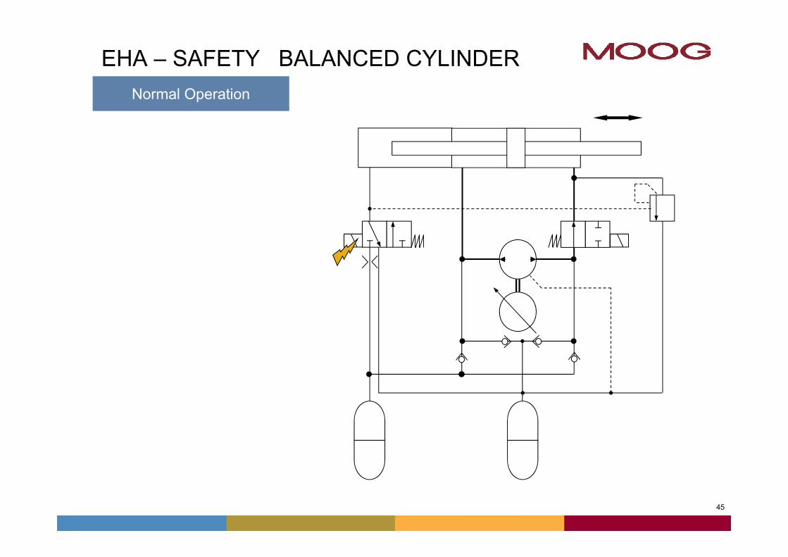
EHA – SAFETY BALANCED CYLINDERNormal Operation
46
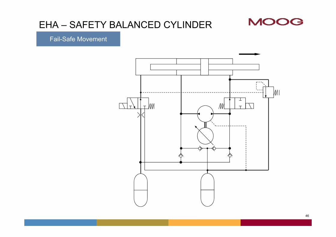
EHA – SAFETY BALANCED CYLINDERFail-Safe Movement
47
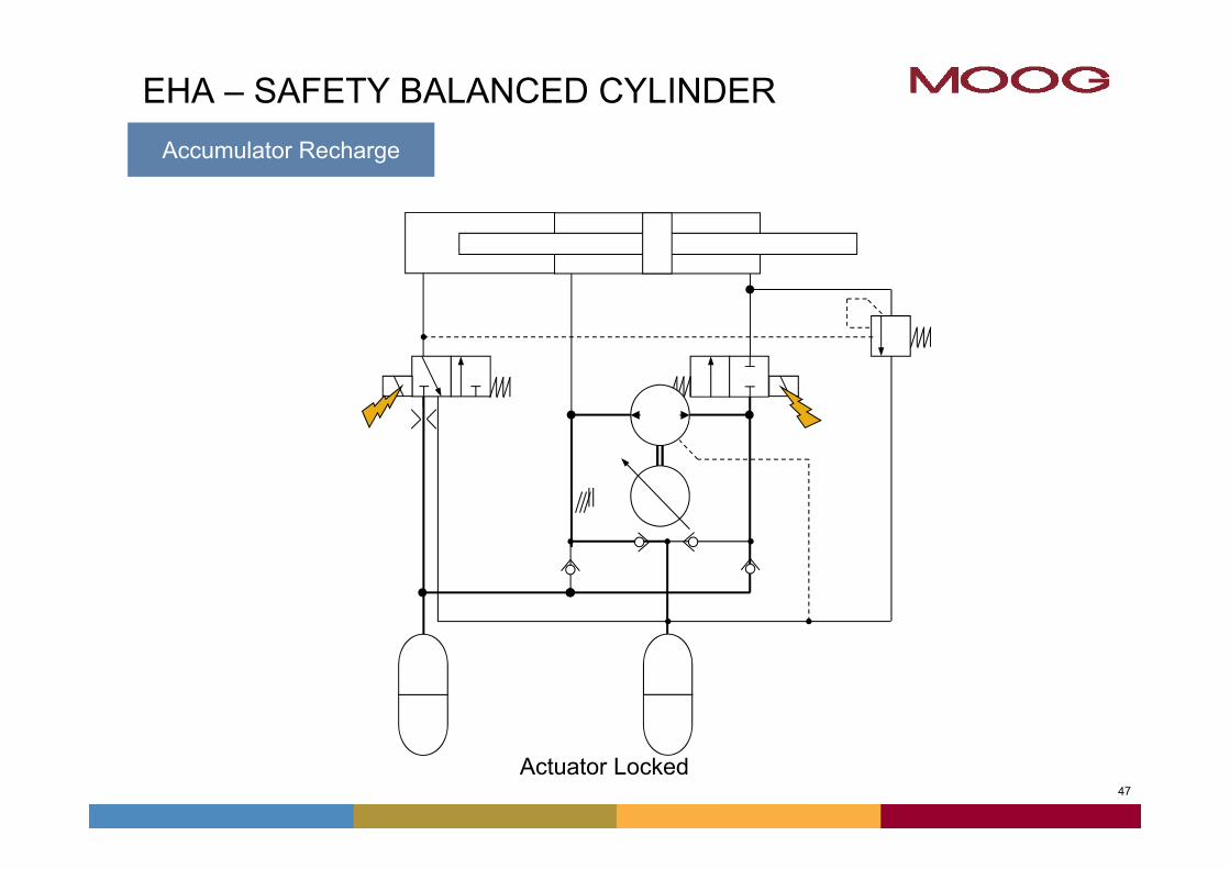
EHA – SAFETY BALANCED CYLINDER
Actuator Locked
Accumulator Recharge
4848
M
M
M
49
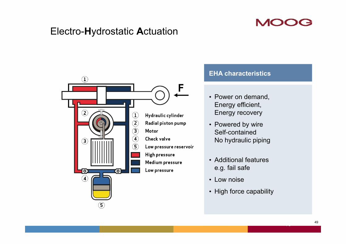
Electro-Hydrostatic Actuation
• Power on demand, Energy efficient,Energy recovery
• Powered by wire Self-containedNo hydraulic piping
• Additional featurese.g. fail safe
• Low noise
• High force capability
EHA characteristics
49
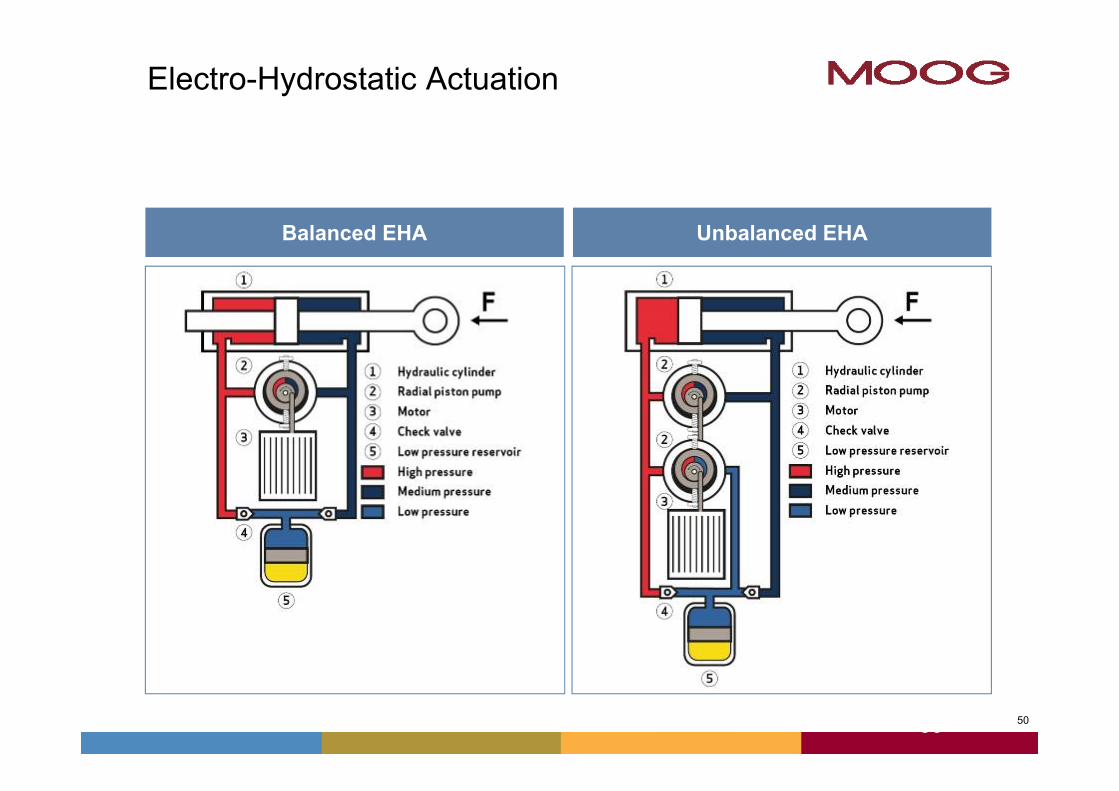
50
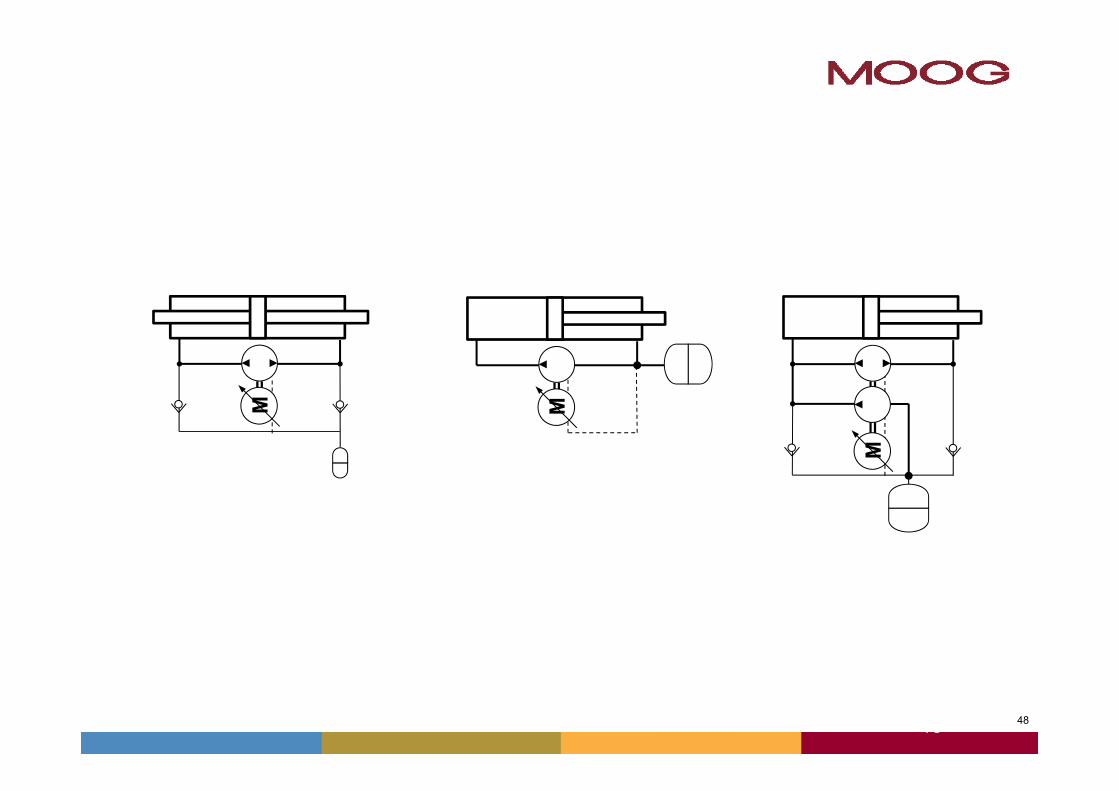
Balanced EHA Unbalanced EHA
50
Electro-Hydrostatic Actuation
Recommended