Electron Positron Circular ColliderPlanning/Progress in China
J. Gao
IHEP
LCWS2014Belgrade, Oct. 6-10, 2014
2
From BEPC to BEPCII BEPC was completed in 1988 with luminosity 11031cm-2s-1 @1.89GeV
BEPC II was completed in 2009 with Luminosity reached: 71032cm-2s-1 @1.89GeV
After BEPCII what is the next high energy collider?

On July 4, 2012, at CERN LHC Higgs Boson was announced found around 126GeV( Scientific opportunity arrived )

Lepton and Hadron Colliders’ History and China Accelerator based High Energy
Physics Development in the Future
4
BEPC II
LC
BEPC
History of BEPC and BEPC II
CEPC+SppCCEPC: Ecm=240GeV e+e- Circular ColliderSppC: Ecm=50-100TeV pp Collider
HIEPAF: High Intensity Electron Positron Accelerator Facility
Old picture!
CEPC+SppC will be constructed with international collaboration and participation

Strategy on Future High Energy Colliders of China1) On “The 464th Fragrant Hill Meeting , June 12-14 , 2013”, Chinese High
Energy Physics Community arrived at the following consensus: a) China supports ILC and will participate to ILC construction with in-kind contributions and requests R&D fund from government b) After the discovery of Higgs, as next collider after BEPCII in China, a
circular e+e- Higgs factory ( CEPC ) and a Super proton- proton Collier (SppC) afterwards in the same tunnel is an important
option and historical opportunity.2) During the meeting of Chinese High Energy Physics Association on “China High
Energy Physics based on Particle Accelerators”, Feb. 28, 2014, it was concluded that:“Circular e+e- Circular Higgs Factory(CEPC) +Super pp Collider (SppC) is the first choice for China’s future high energy physics accelerator.
• It is considered that CEPC (250GeV upper limit) is supplementary to ILC in terms of its energy range down to W and Z boson and to the number of detectors from both machines
• International collaboration and participation are necessary
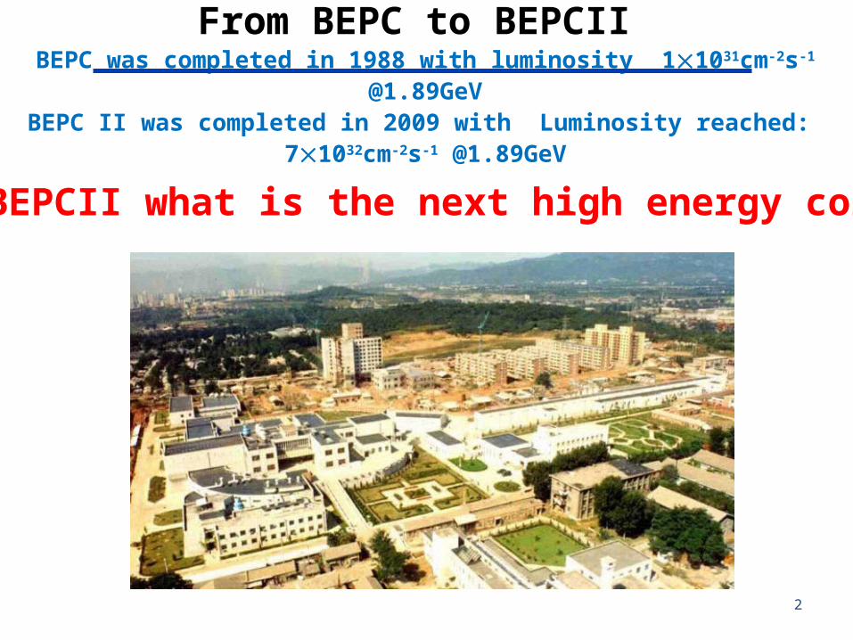
Ways to the future-Larger accelerators :
1 ) Linear colliders : ILC-CLIC ( from Higgs energy to 5TeV,
China participates)
2 ) Circular Colliders : CEPC-SppC e+e- Higgs factory-pp 50~100TeV(machine at home with international
Participation)Precision @ e+e- colliderEnergy frontier @ pp collider
Higher energy Higher precision
e+
e-
LTBCEPC (50km-100km)
Boostr(50Km-100km)
SppC 50-100Km)

1 ) China’s ILC R&D Related Activities after TDR
The key subjects of R&D for accelerators in China (with ILC collaboration)
1) ILC luminosity and backgroud improvements
2) ILC SCRF technology mastering
3) ILC positron source R&D efforts
Three talks in LCWS2014:
1)Dou Wang (IHEP), Yiwei Wang (IHEP), Philip Bambade (LAL), Jie Gao (IHEP), Study of alternative ILC final focus optical configurations
2)J. Zhai, et al, IHEP ILC Test Cryomodule Status
3) S. Jin (IHEP), P. Sievers (CERN), T. Omori (KEK), J.Gao (IHEP), Progress on Stress Analysis of Positron Source Target by AWB Simulation

ILC nominal
(theoretica
l)
ILC nominal
(real)
ILC-low BS
(real)
ILC-high Lum(real)
E/beam (GeV) 250 250 250 250Repetition rate (Hz)
5 5 5 5
Bunch number/pulse
2625 2625 2625 2625
Ne (1010) 2 2 2 2z (um) 300 300 150 150*x/y (mm) 15/0.
415/0.
445/0.
220/0.
2Luminosity by single collision (1034 m-2)
1.8 1.40 1.42 1.82
Luminosity by single collision (inc. vertical waist shift) (1034 m-2)
1.69 1.72 2.21
Total luminosity (inc. vertical waist shift) (1034 cm-2s-1)
2.4 2.22 2.25 2.9

2) CEPC-SppC Organization
Institutional BoardY.N. Gao (TU)J. Gao (IHEP)
Steering CommitteeY.F. Wang(IHEP)
Project DirectorsX.C. Lou(IHEP)Q. Qin (IHEP)
DetectorS. Jin (IHEP)Y.N. Gao (TU)
AcceleratorQ. Qin (IHEP)J. Gao (IHEP)
TheroyH.J. He (TU)S.H. Zhu (PKU)

Internationalization• This is a machine for the world and by the world: not a Chinese
one• As a first step, “Center for Future High Energy Physics (CFHEP)” is
established – Prof. Nima Arkani-Hamed is now the director– Many theorists(coordinated by Nima and Tao Han) and accelerator
physicists(coordinated by Weiren Chou) from all the world have signed to work at CFHEP from weeks to months.
– More are welcome need support from the related management– Current work:
• Workshops, seminars, public lectures, working sessions, …• Pre-CDR
– Future works (with the expansion of CFHEP)• CDR & TDR• Engineer design and construction
– A seed for an international lab Organized and managed by the community
• We established closely collaborate with FCC@CERN

CEPC/SppC starts Many workshops, seminars in China and in the world
– Sep. 2013, Dec. 2013, March. 2014, Spet. 2014, Oct. 2014( ICFA HF2014)…
CEPC+SppC Kick off Meeting ( Sept. 13-14,2013, Beijing)

CEPC/SppC and FCC
• CERN started the Future Circular Collider effort since last year
• FCC kick-off meting in Feb., 2014• ICFA statement On Feb. 21, 2014
at DESY:
ICFA supports studies of energy frontier circular colliders and encourages global coordination
ICFA: international committee for Future acceleratorshttp://www.fnal.gov/directorate/icfa/

CEPC layout
LTB : Linac to Booster
BTC : Booster to Collider Ring
BTC
IP1
IP2
e+ e-
e+ e- Linac (240m)
LTB
CEPC Collider Ring(50Km)
Booster(50Km)
BTC

CEPC+SppC Schedule (Preliminary)
• BEPC II will stop in ~2020
• CPEC– Pre-study, R&D and preparation work
• Pre-study: 2013-15 Pre-CDR by 2014 • R&D: 2016-2020 • Engineering Design: 2015-2020
– Construction: 2021-2027– Data taking: 2030-2036
• SPPC– Pre-study, R&D and preparation work
• Pre-study: 2013-2020• R&D: 2020-2030 • Engineering Design: 2030-2035
– Construction: 2036-2042– Data taking: 2042 -

Preliminary Conceptual Design Report of CEPC-SppC

Luminosity from colliding beams• For equally intense Gaussian beams
• Expressing luminosity in terms of our usual beam parameters
RN
fLy
b
x
2
4
Geometrical factor: - crossing angle - hourglass effect
Particles in a bunch
Transverse beam size (RMS)
Collision frequency
16
where

max
2845
6p
IP
r
f x RN
dtt
xfx
0
2
)2
exp(2
21)(
IPpIP NrRxf
Nxf
x
6
2845)(4)(4 2
max
2
For lepton collider:
For hadron collider:
Formulae from private note of J. Gao
IPRNe
r
61
2845maxy,
re is electron radiusγ is normalized energyR is the dipole bending radiusNIP is number of interaction points
rp is proton radius
max,2
maxx, y J. Gao, Nuclear Instruments and Methods in
Physics Research A 533 (2004) 270–274
J. Gao, Nuclear Instruments and Methods in Physics Research A 463 (2001) 50–61
where
IPy N 0T2
2845maxy, π
Maximum Beam-beam tune shift analytical expressions for lepton and hadron circular colliders

Difference between an e+e- Linear Collider and an e+e- storage ring collider
Linear Collider
Storage ring collider
2 2
0exp2 2hourglass
a a aF K
*y
l
a
02 1 34
,
10.7 10 1 b
hgy IP IP
P MW P MWL cm s R F
cm N
2 17 * *
04 10e b
Dx Dyx y
N P MWL cm s H H
e m m E GeV
P0 is single beam radiation powerPb is single beam power
IPy N 0T2
2845maxy, π
where for storage ring luminosity expression,
has been used
Roughly speaking, linear collider is background limited and circular collider is AC power limited, which corresponds to aiming to reduce background and to reduce AC power for given Luminosities, respectively.

Parameter Unit Value Parameter Unit Value
Beam energy [E] GeV 120 Circumference [C] m 54420
Number of IP[NIP] 2 SR loss/turn [U0] GeV 3.11
Bunch number/beam[nB] 50 Bunch population [Ne] 3.71E+11
SR power/beam [P] MW 51.7 Beam current [I] mA 16.6
Bending radius [] m 6094 momentum compaction factor [p] 3.39E-05
Revolution period [T0] s 1.82E-04 Revolution frequency [f0] Hz 5508.87
emittance (x/y) nm 6.12/0.018 IP(x/y) mm 800/1.2
Transverse size (x/y) m 69.97/0.15 x,y/IP 0.116/0.082
Beam length SR [s.SR] mm 2.17 Beam length total [s.tot] mm 2.53
Lifetime due to Beamstrahlung min 80lifetime due to radiative Bhabha scattering [L]
min 52
RF voltage [Vrf] GV 6.87 RF frequency [frf] MHz 650
Harmonic number [h] 117900 Synchrotron oscillation tune [s] 0.18
Energy acceptance RF [h] % 5.98 Damping partition number [J] 2
Energy spread SR [.SR] % 0.13 Energy spread BS [.BS] % 0.08
Energy spread total [.tot] % 0.16 n 0.23
Transverse damping time [nx] turns 78 Longitudinal damping time [n] turns 39
Hourglass factor Fh 0.692 Luminosity /IP[L] cm-2s-1 2.01E+34
Main parameters for CEPC (Oct. 1, 2014)
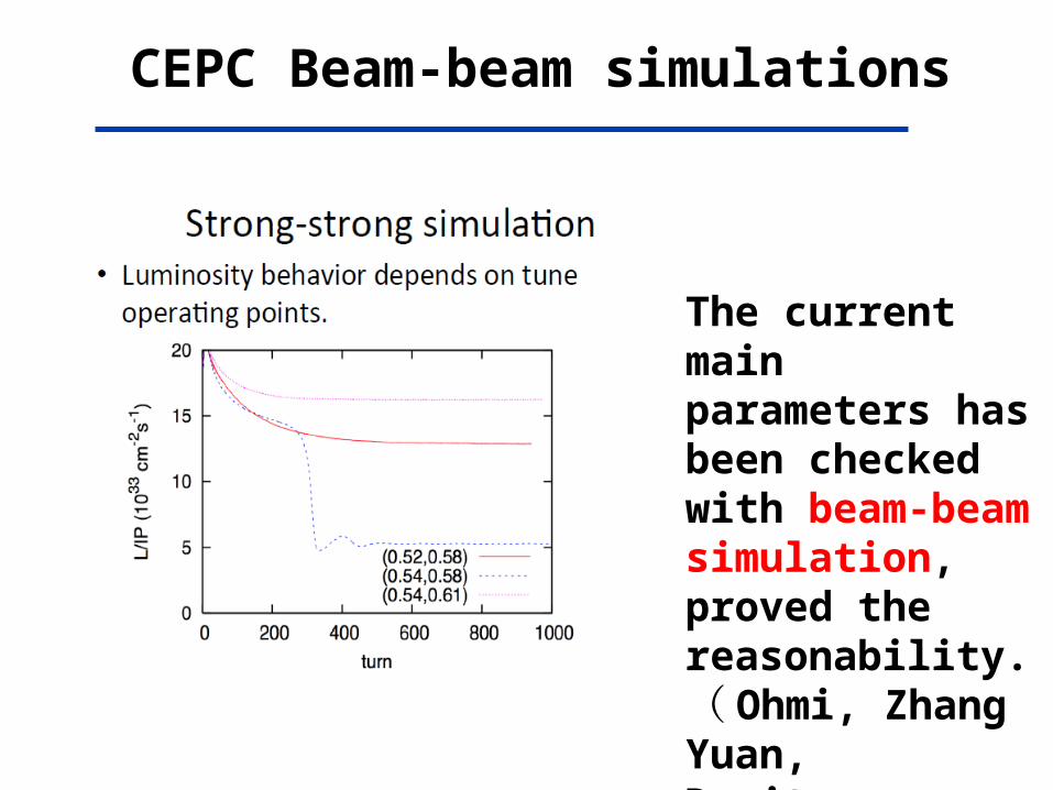
CEPC Beam-beam simulations
The current main parameters has been checked with beam-beam simulation, proved the reasonability.( Ohmi, Zhang Yuan,Demitry Shatilov)

Beam-beam tune shift limit analytical calculations
max
2845
6p
IP
r
f x RN
dtt
xfx
0
2
)2
exp(2
21)(
IPpIP NrRxf
Nxf
x
6
2845)(4)(4 2
max
2
03656.2x
0417.0)( xf
0064.0max
For lepton collider:
For hadron collider:
whereSppC (actual parameter list)
FCC (pp) 0.005 (theory and design)Formulae from private note of J. Gao
)(072.01
28456maxy, CEPC
IP
e
RNr
r_e is electron radiusγ= is normalized energyR is the dipole bending radiusN_IP is number of interaction points
r_p is proton radius
)(11.02 max,maxx, CEPCy
J. Gao, Nuclear Instruments and Methods in Physics Research A 533 (2004) 270–274
J. Gao, Nuclear Instruments and Methods in Physics Research A 463 (2001) 50–61

CEPC Lattice Layout (September 24, 2014)
P.S.
P.S.
P.S.
P.S.
IP1
IP4
IP3
IP2D = 17.3 km
½ RF
RF
RF
RF
RF
½ RF
½ RF
½ RF
RF RF
One RF station: •650 MHz five-cell SRF cavities;•4 cavities/module•12 modules, 10 m each•RF length 120 m
(4 IPs, 1038.4 m each)(4 straights, 849.6 m each)
(8 arcs, 5852.8 m each)
C = 54.374 km

FODO Cells
Length of bending magnet: 19.6mBending radius: 6089m
Length of Qs: 2.0mLength of sextupoles: 0.4mDistance between magnets: 0.3mLength of each cell: 47.2m

Arc
120*FODO cells+ dispersion suppressors at both sides
Total length: 5852.8m

FODO cell at straight section
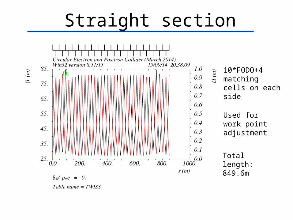
Straight section
10*FODO+4 matching cells on each side
Used for work point adjustment
Total length: 849.6m
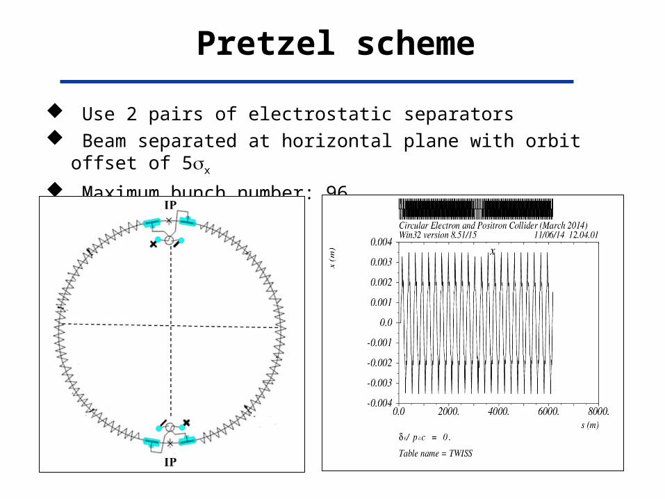
Use 2 pairs of electrostatic separators Beam separated at horizontal plane with orbit offset of 5x
Maximum bunch number: 96
Pretzel scheme

CEPC Magnets’ specificationsDipole magnet type A type BQuantity 1984Beam energy (GeV) 120Bending angle (rad) 3.17E-03Bending radius (m) 5683.74Magnetic gap (mm) 100 (as LEP)Magnetic Length (m) 18Maximum field strength (T) 0.07Good field region, GFR (mm)Field uniformity across GFRIntegral field deviation (magnet to magnet)
Quadrupole magnet type A type BQuantity 2304Beam energy (GeV) 120Aperture diameter(mm) 125Magnetic Length (m) 2Maximum field gradient (T/m) 10Good field region, GFR radius (mm)Harmonic field errors across GFRIntegral field deviation (magnet to magnet)
Sextupole magnet type A(SF) type B(SD)Quantity 992 992Beam energy (GeV) 120 120Aperture diameter(mm) 150 (as LEP) 150Magnetic Length (m) 0.4 0.7Strength of sextupole field (T/m 2̂) 180 180Good field region, GFR radius (mm)Harmonic field errors across GFR
Correctors type A type BQuantityBeam energy (GeV)Magnetic gap (mm)Magnetic Length (m)Maximum field (T)Good field region, GFR (mm)Field uniformity across GFR

IPEntrance:betx=81mbety=27m
Whole FFS opticsIP:betx*=0.8mbety*=0.0012mL*=1.5m
29
Total length: 341 m

CEPC lattice with FFS

Lattice of the whole ring
Dynamic aperture: ~20x/ 100y for on momentum particlesFor first try, zero length of sextupoles in FFS used
Off momentum:1%, 2%
On momentum

Booster bypass designBooster: Outer of Collider
CEPCCEPC
• For the moment, the energy of Booster is chosen 6GeV, the ratio Energy gain is 20.
• There are two issues rest to be checked carefully on the booster energy choice:
1) The low dipole field of 37 Gauss
at 6GeV with 1/5 being the residual magnetic field of dipole
magnets 2) The space charge effect

Booster key parametersParameter Symbol Unit Value
Injection energy Einj GeV 6
Ejection energy Eej GeV 120
Circumference C km 53.6192
Revolution frequency f0 kHz 5.591
Bending radius km 6.520
Main bending field T 0.0614
SR loss/turn U0 GeV 2.814
Bunch number nb 50
Bunch population Nb 1010 1.96
Beam current Ibeam mA 0.889
Momentum compaction p 10-5 7.774
Chromaticity x/y -47.58/-50.36
Emittance x0,ej nm 24.02
RF frequency f RF MHz 1300.0
RF Voltage VRF GV 5.12
Harmonic number h 232511
Energy spread E,ej 10-3 1.273
Bunch length z mm 3.89
Length of normal cells Lcell m 71.3
Number of cells Ncell m 752
Transverse phase advance in a cell x/y 60 /60 Quadrupole strength in a cell KQF/ KQD m-2 2.8315/-2.8315
Maximum in cells x,c,maxy,c,max m 123.21/ 123.21
Maximum in ring x,maxy,max m 127.00/ 124.94
Maximum dispersion in cells Dc,max m 0.8744
Maximum dispersion in ring Dmax m 0.8744
Sixtupole strength KSF/ KSD m-3 0.1924 /-0.3124
Transverse tune x/y 119.72/119.73
Longitudinal tune s 0.320
Damping time x/y/s ms 15.2/15.2/7.63

FODO cell Length L 47.2 71.3 94.4 m
Quadrupole strength |kQlQ| L-1 0.044 0.029 0.022 m-1
Maximum beta function in a cell max L 81.2 122.6 162.3 m
Maximum dispersion in a cell Dx L2 0.38 0.86 1.52 m
Betatron tune x,y L-1 189.2 125.3 94.6
Momentum compaction factor p L2 3.43 7.83 13.72 10-5
Chromaticity L-1 86.4 57.2 43.2
Sextupole strength SF/SD |ksls| L-3 0.15/0.24 0.044/0.070 0.019/0.030 m-2
Nature emittance x0 L3 6.8 23.44 54.40 nm
Synchrotron tune (VRF=5 GV) sL 0.204 0.31 0.41
Maximum Betatron beam size x/y L2 0.74/0.53 1.70/1.20 2.97/2.10 mm
Maximum Beam orbit spread xE L2 0.49 1.12 1.97 mm
Maximum horizontal m beam size x L2 0.89 2.03 3.57 mm
Bunch length (VRF=5 GV) z L 1.84 2.78 3.68 mm
Booster lattice parameters scale to cell length

Transfer from linac to booster
• Switch Yard Arcs• Match to the Linac• Match to the Booster• Vertical slope line
e+ arc Match to booster for e+
Linac Match to Linac Switch
e- arc Match to booster for e-
Booster

Vertical slope line (from surface to underground channel)
Slope = 1:10, L~500m,Dx,max~4m

Match from linac to booster
x x(Dx )2 = 127(110-30.006)2 = 4.6 nmrad<<x, L of 0.1 mmrad from
linac

Transfer from booster to collider
V. Septum (Cop. or Iron)
Lc
22 SSeeccttiioonn 4Lc
V. Septum (Cop. or Iron)
Lc

CEPC Injection Scheme1. Betatron Injection
2.Two Kicker Bumps

Injection linac
6GeV Conventional Linac (option I)
Option II is 6GeV 1.3GHz ILC type linac with XFEL usage

Injection linac
Challenge
1. Nbunch e+=21010 3.2nC/bunch e+
2. Polarization
• Main parameters
Parameter Symbol Unit Value
E- beam energy Ee- GeV 6
E+ beam energy Ee+ GeV 6
Pulse width Δt ns 0.7
Repetition rate frep Hz 100
E- bunch population Ne- 2×10¹⁰
E+ bunch population Ne+ 2×10¹⁰
Energy spread (E+/E-) σE <1×10⁻³

Injection linac
Linac Frequency: 2856MHz Normal conducting
Conventional Positron Source and a 0.2GeV Positron Beam Transport Line

Electron source• Unpolarized Electron Source (Baseline)
• Polarized Electron Source (R&D)
Electron Gun
Gun type Thermionic Triode Gun
Cathode Y824 (Eimac) Dispenser
Beam Current (max.) A 10
High Voltage of Anode kV 150-200
Bias Voltage of Grid V 0 ~ -200
Pulse duration ns 0.7
Repetition Rate Hz 50~100
1. R&D on a superlattice GaAs/GaAsP photocathode
2. R&D on a (100kV-150kV) DC gun

Positron source
• Unpolarized Positron Source
Conventional Positron Source + 0.2Gev e+ transport line
Positron sourceE- beam energy on the target GeV 4E- bunch charge on the target nC 10
Target material W-Re Target thickness mm 14
E+ Yield Focus device Flux Concentrator 5Tesla
E+ Energy pre-accelerate MeV 200

CEPC SRF System Layout
8 RF sections In each ~ 120m section •Main ring:- 12 x 10m cryomodules- 650 MHz 5-cell SRF cavity- 4 cavities / cryomodule•Booster:- 4 x 12m cryomodules- 1.3 GHz 9-cell SRF cavity- 8 cavities / cryomodule
45
Superconducting RF Cavity•~ 20 x CW gradient •less disruption to beam•100s times more efficient•LLRF benefitscompared to normal conducting

CEPC Lattice Layout (September 23, 2014)
P.S.
P.S.
P.S.
P.S.
IP1
IP4
IP3
IP2D = 17.3 km
½ RF
RF
RF
RF
RF
½ RF
½ RF
½ RF
RF RF
One RF station: •650 MHz five-cell SRF cavities;•4 cavities/module•12 modules, 8 m each•RF length 120 m
(4 IPs, 1038.4 m each)(4 straights, 849.6 m each)
(8 arcs, 5852.8 m each)
C = 54.374 km

qb = 60 nC
CEPC SRF System Design Criteria
47
PSR 100 MW Vrf 6.87 GeVU0 = 3 GeV
T
frf
Q0
η↑, τBS ↑, σz↓ ρ = 6.1 km
Pcoupler < 300 kWPcoupler < 300 kW Ncavity↓
Eacc
Ncell
R/Q
Impedance T.H.
↑
HOM Power
↓
Vc¥
Lc
Riris
Ep Bp
↓
¥
↑
↓
HOM QL
QL
GHOM R/Q, k↓
H
H
H
H
Rs
Thin Film
Nmodule
Ncav/module¥ H
¥H
HOM DampingHOM Damping
WGHookFerrite
Bulk Nb
Nb3Sn/Nb
Nb/Cu
N-dope
↓
Dynamic Cryo LoadDynamic Cryo Load↑↑
H
Cavity ShapeCavity Shape
Large irisLow loss
PS EfficiencyPS Efficiency↑ Cavity MaterialCavity Material
I = 33.3 mA Nb = 50
Mode Propagate
¥
C
H
RF AC < 200 MW ?
Cryo AC < 20 MW ?
↓
2 K
4.2 K
↓
↓
f0 = 5.6 kHz
¥
¥
Vc↓
H: handling or LLRF control

CEPC SRF Cavity Parameters (v2-2014-09-21)Parameter Symbol Unit Main Ring Booster
RF frequency fRF MHz 650 1300
RF voltage VRF GV 6.87 5.04
Operating gradient Eacc MV/m 15.5 19.0
Number of cells Ncell - 5 9
Effective length Leff m 1.154 1.038
Operating voltage Vc MV 17.9 19.7R/Q R/Q Ω 514 1036Geometry factor G Ω 268 270Operating temperature T K 2 2Quality factor at operating gradient Q0 - 2E+10 2E+10Duty factor DF - 100% 22%*HOM 2K cw heat load per cavity WHOM2K W 6.5 0.15
HOM 5K cw heat load per cavity WHOM5K W 19.5 0.3
HOM 80K cw heat load per cavity WHOM80K W 195 14.55
External Q of input coupler Qext - 2.4E+06 1E+07
RF power per cavity Pin kW 260 20
Number of cavities NCV - 384 256
Cavities in one cryomodule NCV/CM - 4 8
Cryomodule length LCM m 10 12
Number of cryomodules NCM - 96 32
Cryomodules per RF section NCM/RFS - 12 4
* Duty factor of the booster dynamic cryogenic heat load in 6 s for electron or positron (1 s 6 GeV injection from linac to booster, 4 s linear ramping to 120 GeV of booster RF voltage, and 1 s full energy ejection to main ring). The duty factor is 5.2 % in the whole 90 s injection period (fist electron and then positron) if the cryogenic response is slow enough. For injection to main ring from zero current, the duty factor is 7.8 %.

SRF parameters of CEPC
units Main Ring Booster
fRF MHz 650 1300
U0 ( single beam ) GeV 3 3
Beam current of e-&e+ mA 2*16=32 0.9
Total beam power (SR) MW 100 2.7
total RF voltage GV 7 6
Eacc MV/m 8.8 15
cavity cells 5 9
cavity numbers 720 320
Input power per cavity kW 139 20
Total RF power MW 100 6.4
LLRF station numbers 720 320
Cryo module numbers 180 (4cav/ module) 40
Another key R&D collaboration item is on CEPC SRF systems, both for main ring and for booster

SRF selections of CEPC
parameters CEPC –4.5K CEPC—2K LEP-2 4.5K
5cell SCC 720 sputtered? 400 Bulk Nb 4cell 288 sputtered
Eacc MV/m 9 15 6 / 7.5
Q0 1E+9 1E+10 3.2E+9
R/Q 500 500 400
Vc/cav (MV) 9.72 17.5 12
Pc/cav (W) 189 61.3 70.1
Heat (kW) 209*720=150.5 81.3*400=32.5 92.5*288=26.64
Total cryo power (MW) 150.5*230=34.6 32.5*900=29.3 26.64*230=6.13
Number Cryo. module 180 100 72
RF input power (kW) 139kW/cav 250kW/cav ? 125kW/cav
Number of SSA 720 400 --
Number of klystron 180*(700kw/4cav) 100*(1.2Mw/4cav)
36*(1200kw/8cav)
Power supply (MW) 222+35 / 182+35 222+29 / 182+29 79+6
HOM (hook/ferrite) W 500?/6500 500?/6500 500?
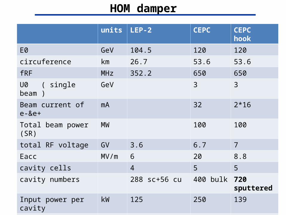
HOM damper
units LEP-2 CEPC CEPC hook
E0 GeV 104.5 120 120
circuference km 26.7 53.6 53.6
fRF MHz 352.2 650 650
U0 ( single beam ) GeV 3 3
Beam current of e-&e+ mA 32 2*16
Total beam power (SR) MW 100 100
total RF voltage GV 3.6 6.7 7
Eacc MV/m 6 20 8.8
cavity cells 4 5 5
cavity numbers 288 sc+56 cu 400 bulk 720 sputtered
Input power per cavity kW 125 250 139
Total RF power MW 40 100 100
P(HOM)/cav. W 500? 6500 500 ?
Cryostat module numbers
72(4cavities/ module)
200 180

SRF of booster of CEPC
parameters CEPC –4.5K CEPC—booster2K LEP-2 4.5K
9cell SCC 720 sputtered? 320 Bulk Nb 4cell 288 sputtered
Eacc MV/m 9 20 6 / 7.5
Q0 1E+9 2E+10 3.2E+9
R/Q 500 900 400
Vc/cav (MV) 9.72 20.9 12
Pc/cav (W) 189 24.4 70.1
Heat (kW) 209*720=150.5 44.4*320=14.2 92.5*288=26.64
Total cryo power (MW) 150.5*230=34.6 14.2*900=12.8 26.64*230=6.13
Number Cryo. module 180 40 72
RF input power (kW) 139kW/cav 20kW/cav ? 125kW/cav
Number of SSA 720 -- --
Number of klystron 180*(700kw/4cav) 40*(160kw/8cav) 36*(1200kw/8cav)
Power supply (MW) 222+35 / 182+35 1.2*6.4+12.8=20.5 79+6
HOM (hook/ferrite) W 500?/6500 100? 500?

Cavity Design
Frequency(MHz) fRF 650
Gradient(MV/m) Eacc 15MV/m
Operating voltage Vc 17.18MV
Cell NO. Ncell 5
Effective length Lc 1153mm
Cavity NO. Ncav 400
Module length(m) Lmodule 3.053
Module NO.(1 cavities/ module)
Nmodule 400
R/Q(Ω) R/Q 506
Quality factor (2K) Q0 Q0=2*1010
RF coupler Qext Qext 2.33*106

Frequency(MHz) fRF 650
Voltage(GV) VRF 6.87
SR power(MW) PSR 100
Power/cavity (kW) P0 250
Operating temperature(K)
T 2
Quality factor (2K) Q0 Q0=2*1010
2K heat load(kW) W2K 19.05
5K heat load (kW) W5K 37.97
80 K heat load (kW) W80K 189.85
Total Cryogrnic AC power(MW)
Wcyo. 29
Total AC power(MW warm absorber)
WAC 251
Parameters Related to RF System
In order to extract the large number of HOM power: 1 cavity/module. HOM damper at room temperature (6.5 kW/cavity);

55
Impedance budget • Resistive wall impedance is calculated with analytical formulas• Impedance of the RF cavities is calculated with ABCI
Object Contributions
R [k] L [nH] kloss [V/pC] |Z///n|eff []
Resistive wall (Al) 6.6 87.1 210.9 0.0031
RF cavities (N=378) 29.3 -- 931.2 ---
Total 35.9 87.1 1142.1 0.0031
)()()( 2 sLcsRcsW
-10 -5 0 5 10-1500
-1000
-500
0
500
1000
1500
z, mm
wak
e, V
/pC
BeamRWRFTotal

56
Single-bunch effects
Parameter Symbol, unit Value
Beam energy E, GeV 120
Circumference C, km 53.6
Beam current I0, mA 16.6
Bunch number nb 50
Natural bunch length l0, mm 2.66
Emittance (horz./vert.) x/y, nm 6.79/0.02
RF frequency frf, GHz 0.65
Harmonic number h 116245
Natural energy spread e0 1.5E3
Momentum compaction factor p 4.15E5
Betatron tune x/y 179.08/179.22
Synchrotron tune s 0.199
Damping time (H/V/s) x/y/z, ms 14/14/7(paramter_lattice20140416)

57
• Bunch lengthening– Steady-state bunch shape is obtained by Haissinski equation– Bunch is shortened due to the capacitive impedance of the RF
cavity(only resistive wall and RF cavity considered)
Pseudo-Green function wake (z=0.5mm) Steady-state bunch shape
• Longitudinal microwave instability– Keil-Schnell criterion:
– The threshold of the longitudinal impedance is |Z///n| < 0.026 .
eff
lep
th
n
ZR
e
E
I||
2 20
0 10 20 30 40-9000
-5000
-1000
3000
7000
z, mm
wak
e, V
/pC
BeamRWRFTotal
-5 -4 -3 -2 -1 0 1 2 3 4 50
0.5
1
1.5
2x 10
11
z/z
Bea
m li
ne d
ensi
ty (
a.u.
)
without wakewith wake

58
• Bunch lengthening with SuperKEKB’s geometry wake– LER wake+RW+RF (bunch is lengthened by 9.0%)
– HER wake+RW+RF (bunch is lengthened by 18.5%)
0 10 20 30 40-4
-3
-2
-1
0
1
2x 10
4
z, mm
wak
e, V
/pC
BeamRWRFSuperKEKB LERLER+RW+RF
0 10 20 30 40-5
-4
-3
-2
-1
0
1
2
3x 10
4
z, mm
wak
e, V
/pC
BeamRWRFSuperKEKB HERHER+RW+RF
-5 -4 -3 -2 -1 0 1 2 3 4 50
0.5
1
1.5
2x 10
11
z/z
Bea
m li
ne d
ensi
ty (
a.u.
)
without wakewith wake
-5 -4 -3 -2 -1 0 1 2 3 4 50
0.5
1
1.5
2x 10
11
z/z
Bea
m li
ne d
ensi
ty (
a.u.
)
without wakewith wake

59
• Space charge tune shift
• Coherent synchrotron radiation z1/2/h3/2=9.2 (=> CSR shielded)
– The threshold of bunch population for CSR is given by
– The CSR threshold in BAPS is Nb,Th = 5.01012 >> Nb = 3.71011.
– CSR is not supposed to be a problem in BAPS.
2/3
2/1
3/4
3/1
,2 h
NrS z
zs
be
y = 1.7e4, x = 5.0e6
12.0500.thS
(K. Bane, Y. Cai, G. Stupakov, PRST-AB, 2010)
ds
sss
sNr
yxyx
yx
z
beyx ))()()((
)(
)2( ,
,
32/3,
60
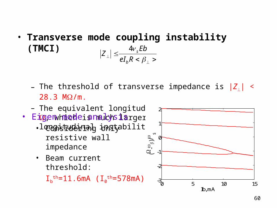
• Transverse mode coupling instability (TMCI)
– The threshold of transverse impedance is |Z| < 28.3 M/m.– The equivalent longitudinal impedance is 2.66 , which is much larger
than that of the longitudinal instability.
ReI
EbZ
b
s4
• Eigen mode analysis • Considering only resistive wall
impedance• Beam current threshold:
Ibth=11.6mA (I0
th=578mA)
0 5 10 15-3
-2
-1
0
1
2
Ib, mA
(-
)/
s

61
Multi-bunch effects
• Transverse resistive wall instability
with pn = 2frev (pnb + n + x,y)
p
pnyx
bb ZeeE
cIn ppn )(Re)/(4
1 220 )/(
,
The growth rate for the most dangerous instability mode is 1.1 Hz (=0.9 s) in the vertical plane with mode number of = 20.
The growth time is much higher than the transverse radiation damping time.
The resistive wall instability is not supposed to happen in the main ring! Growth rate vs. mode number
in the vertical plane
0 10 20 30 40 50-3
-2
-1
0
1
2
1/
y, Hz
(20, 1.1)

62
Electron cloud instability
KEKB SuperKEKB SuperB CEPC
Beam energy E, GeV 3.5 4.0 6.7 120
Circumference L, m 3016 3016 1370 53600
Number of e+/bunch, 1010 3.3 9 5.74 37.1
Emittance H/V x/y, nm 18/0.36 3.2/0.01 1.6/0.004 6.79/0.02
Bunch length z, mm 4 6 5 2.66
Bunch space Lsp, ns 2 4 4 3575.8
Single bunch effect
Electron freq. e/2, GHz 35.1 150 272 183.9
Phase angle ez/c 2.94 18.8 28.5 10.3
Threshold density e,th, 1012m-3 0.7 0.27 0.4 1.1
Multi-bunch effect
p-e per meter n, p/(m) 5.0E8 1.5E9 3.6E9 1.1E10
Characteristic frequency G, MHz 62.8 87.2 69.6 5.9
Phase angle GLsp/c 0.13 0.35 0.28 21.2• Threshold density for the single bunch effect is considerable high.
• The phase angle for the multi-bunch effect is about two orders higher, so the electrons are not supposed to accumulate and the multipacting effects is low.

63
Beam ion instability• Ion trapping
– With uniform filling pattern, the ions with a relative molecular mass larger than Ax,y will be trapped.
• Fast beam ion instability– With uniform filling, the growth time considering ion oscillation
frequency spread is 6.9ms, which is lower than the damping time.– Fast beam ion instability could occur with uniform filling.
yxyx
bpbyx
SrNA
,, )(2
2/12/32/3
2/12/122/311
)(][5][
A
cLrrnNTorrps
yxy
seppebbinst
ionsBsep
instinstnL
c
2211
– The ions will not be trapped by the beam.
0 0.5 1 1.5 2 2.5
x 104
0
0.5
1
1.5
2
2.5
3x 10
4
z, m
Ax/A
y
X: 1.077e+004Y: 421.5
AxAy

SppC Layout
Medium Energy Booster(4.5Km)
Low Energy Booster(0.4Km)
IP4 IP3
SppC Collider Ring(50Km)
Proton Linac(100m)
High Energy Booster(7.2Km)

Parameter Value Unit
Circumference 52 km
Beam energy 35 TeV
Dipole field 20 T
Injection energy 2.1 TeV
Number of IPs 2 (4)
Peak luminosity per IP 1.2E+35 cm-2s-1
Beta function at collision 0.75 m
Circulating beam current 1.0 A
Max beam-beam tune shift per IP 0.006
Bunch separation 25 ns
Bunch population 2.0E+11
SR heat load @arc dipole (per aperture) 56 W/m
SppC main parameters
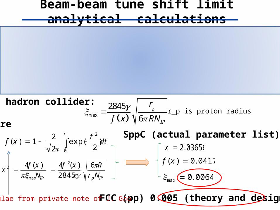
Beam-beam tune shift limit analytical calculations
max
2845
6p
IP
r
f x RN
dtt
xfx
0
2
)2
exp(2
21)(
IPpIP NrRxf
Nxf
x
6
2845)(4)(4 2
max
2
03656.2x
0417.0)( xf
0064.0max
For lepton collider:
For hadron collider:
whereSppC (actual parameter list)
FCC (pp) 0.005 (theory and design)Formulae from private note of J. Gao
)(072.01
28456maxy, CEPC
IP
e
RNr
r_e is electron radiusγ= is normalized energyR is the dipole bending radiusN_IP is number of interaction points
r_p is proton radius
)(11.02 max,maxx, CEPCy
J. Gao, Nuclear Instruments and Methods in Physics Research A 533 (2004) 270–274
J. Gao, Nuclear Instruments and Methods in Physics Research A 463 (2001) 50–61

p-Linac: proton superconducting
linac
p-RCS: proton rapid cycling
synchrotron
MSS: Medium-Stage Synchrotron
SS: Super Synchrotron
Injector chain (for proton beam)
Ion beams have dedicated linac (I-Linac) and RCS (I-RCS)
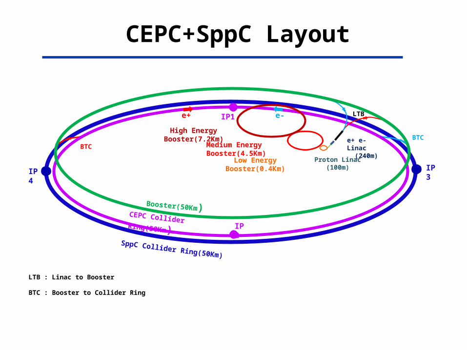
CEPC+SppC Layout
LTB : Linac to Booster
BTC : Booster to Collider Ring
BTC
IP1
IP2
e+ e-
e+ e- Linac (240m)
LTB
CEPC Collider Ring(50Km)
Booster(50Km)
BTCMedium Energy Booster(4.5Km)
Low Energy Booster(0.4Km)
IP4 IP3
SppC Collider Ring(50Km)
Proton Linac(100m)
High Energy Booster(7.2Km)

Possible site (example)• 300 km from Beijing• 3 h by car• 1 h by train
69/45
BeijingQinhuangdao
Tianjing
Beidaihe

CEPC/SppC Siting (example)• Preliminary selected Qinhuangdao ( 秦皇岛) (one of the candidate
sites)• Strong support by the local government

Good geological condition
• Base rock type: granite • Base rock depth: 0.5 - 2 m• Earth quake: no more than 7 , 0.10g• Earth vibration(RMS, nm):
71/45
Zhangjiakou Huailai Qinhuangdao Tianjing Huairou
1~100hz ~12 ~40 ~1.9 ~470 ~60
4~100hz ~7 ~14 ~0.8 ~24
Building the tunnel in granite will have lowest cost

High Energy Accelerators Comparisons
Tevatron
LHC
BEPC
KEKB
CEPC-SppC
ILC
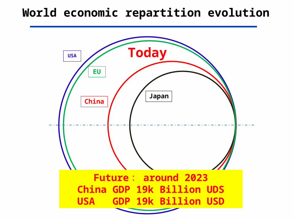
World economic repartition evolution
USA
EU
ChinaJapa
n
Future : around 2023China GDP 19k Billion UDSUSA GDP 19k Billion USD
Today

ICFA Chairman’s view
ICFA Chairman , Fermi National Lab director , Prof. Nigel Lockyer wrote an article: “Particle physics: Together to the next frontier”,Nature, Volume 504, Issue 7480,18 December 2013.(http://www.nature.com/news/particle-physics-together-to-the-next-frontier-1.14364)
Prof. Nigel Lockyer wrote: “If China does jump ahead, it will change the landscape of science.”

Summary (1)1. Discovery of Higgs boson around 126GeV provides
more opportunities for future colliders around the world
2. In addition to ILC collaboration, CEPC/SppC has the highest priority among all the proposals for future HEP accelerators in China
3. We are experiencing a very excited period of time and China should and could take more responsibilities for the high energy physics community world wide in both international projects, such as ILC and homed based CEPC/SppC with world participation
4. CEPC/SppC will collaborate closely with ILC and FCC

Summary (2)1. The most urgent is collider lattice design including FFS
with enough dynamic aperture
2. Once the collider is working in design, one could try to optimize the machine design in reducing beam radiation power, or, AC power
3. Key technologies for CEPC/SppC need dedicated R&D in the next five years (the 13th five year plan of China), such SCRF technologies, RF sources, SC magnets, Detector technologies, Vacuum chamber…infrastructure SC lab…

Acknowledgements
1. Thanks to organizing committee to invite me to give this talk
2. During preparation of this talk, I have benefited many discussions and materials both from the CEPC/SppC Group and from ILC Group
Thank you for your attention
Recommended