FINAL REPORT JULY 2002
REPORT NO. 01-22
CORDSTRAP™ W/MK-82 BOMBS, TP-94-01,
"TRANSPORTABILITY TESTING PROCEDURES"
Prepared for:
U.S. Air Force Air Expeditionary Battlelab 360 Gunfighter Ave Mt Home AFB, ID 83648
Distribution Unlimited
VALIDATION ENGINEERING DIVISION MCALESTER, OKLAHOMA 74501-9053
20020805 180
AVAILABILTY NOTICE
A copy of this report will be furnished each attendee on automatic distribution.
Additional copies or authority for reprinting may be obtained by written request
from:
Director U.S. Army Defense Ammunition Center ATTN: SOSAC-DEV 1 C Tree Road, Bldg. 35 McAlester, OK 74501-9053
Reports may also be downloaded or viewed in PDF format from our web site at:
http://www/dac.armv.mil/DEV/TestReports
DISTRIBUTION INSTRUCTIONS
Destroy this report when no longer needed. Do not return.
***
Citation of trade names in this report does not constitute an official endorsement.
***
The information contained herein will not be used for advertising purposes.
REPORT NO. 01-22 JULY 2002 CORDSTRAP W/MK82 500-POUND BOMBS TP-94-01, TRANSPORTABILITY TESTING PROCEDURES
ABSTRACT
The U.S. Army Defense Ammunition Center (DAC), Validation Engineering
Division, (SOSAC-DEV), was tasked by the USAF Air Expeditionary Battlelab
to conduct transportability testing and to validate Cordstrap™ material as an
alternative to using wood for blocking and bracing the MK-82 500-pound
bombs in an end-opening 20-foot-long intermodal container. Based on our
review and testing, the Cordstrap™ material was not effective as an alternative
to wood for restraint of the MK-82 bombs in an end-opening intermodal
container.
During testing, the Cordstrap™ either stretched excessively or broke which
allowed the payload to move. Also, the airbags that were used during initial
testing lost pressure due to temperature changes and would not hold the load
tightly. The Cordstrap™ system is dependent on the intermodal container
having lashing rings located along the floor and roof. Not all intermodal
containers have lashing rings; and, therefore, the system could not be used in
containers without rings. Additionally, the Cordstrap™ material was not
effective as an alternative to wood since considerable wood dunnage was still
required to block and brace the payload. Cordstrap™ material could not be
used as a forward bulkhead and required excessive time and labor to install.
Prepared by: Reviewed by:
PHILIP W. BARICKMAN JERRY W. BEAVER Lead Validation Engineer Chief, Validation Engineering Division
U.S. ARMY DEFENSE AMMUNITION CENTER VALIDATION ENGINEERING DIVISION
MCALESTER, OK 74501-9053
REPORT NO. 01-22
CORDSTRAP™ W/MK-82 BOMBS TP-94-01, "TRANSPORTABILITY TESTING PROCEDURES"
TABLE OF CONTENTS
PART PAGE NO.
1. INTRODUCTION 1-1 A. BACKGROUND 1-1 B. AUTHORITY 1-1 C. OBJECTIVE 1-1 D. CONCLUSION 1-1
2. ATTENDEES 2-1 3. TEST EQUIPMENT 3-1 4. TEST PROCEDURES 4-1
A. RAIL TEST 4-1 B. ON/OFF ROAD TEST 4-3
1. HAZARD COURSE 4-3 2. ROAD TRIP 4-4 3. PANIC STOPS 4-4 4. WASHBOARD COURSE 4-4
C. OCEAN GOING VESSEL TEST (STS) 4-5 5. TEST RESULTS 5-1 5.1 TESTING DATE-(17-19 Oct 2001) 5-1
A. RAIL TEST 5-2 B. ON/OFF ROAD TEST 5-6
1. HAZARD COURSE 5-6 2. ROAD TRIP 5-7 3. PANIC STOPS 5-7 4. WASHBOARD COURSE 5-8
C. SHIPBOARD TRANSPORTATION SIMULATOR 5-9 D. AIR BAG HISTORY 5-10
5.2 TESTING DATE- (28 Jan 2002) 5-13 A. RAIL TEST 5-15
6. ACCELEROMETER DATA 6-1 7. DRAWINGS 7-1
PART 1 - INTRODUCTION
A. BACKGROUND. The U.S. Army Defense Ammunition Center (DAC),
Validation Engineering Division (SOSAC-DEV), was tasked by the Air Force Air
Expeditionary Battlelab to conduct transportability testing using the Cordstrap
material to secure the MK-82 500-pound bombs in an end-opening 20-foot-long
intermodal container. Loading procedures specified in AMC Drawing 19-48-8643
were used as a guideline. The container load was tested in accordance with
TP-94-01, "Transportability Testing Procedures."
B. AUTHORITY. This test was conducted IAW mission responsibilities
delegated by the U.S. Army Operations Support Command (OSC), Rock Island,
IL. Reference is made to the following:
1. AR 740-1, 15 June 2001, Storage and Supply Activity Operation.
2. IOC-R, 10-23, Mission and Major Functions of USADAC, 7 January 1998.
C OBJECTIVE. The objective of the testing was to validate the use of
Cordstrap™ material as an alternative to wood for restraint of the
MK-82 500-pound bombs in an end-opening 20-foot-long intermodal container.
D. CONCLUSION. Based on our review and testing the Cordstrap™ material
was not effective as an alternative to wood for restraint of the MK-82 500-pound
bombs in an end-opening 20-foot-long intermodal container. During testing the
Cordstrap™ either stretched excessively or broke which allowed the payload to
move. Also, the airbags that were used during initial testing lost pressure due to
temperature changes and would not hold the load tightly. The Cordstrap
system is dependent upon the intermodal container having lashing rings located
along the floor and roof. Not all intermodal containers have lashing rings; and,
therefore, the system could not be used in containers without rings. Additionally,
l-i
the Cordstrap material was not effective as an alternative to wood since
considerable wood dunnage was still required to block and brace the payload.
The Cordstrap material could not be used as a forward bulkhead and required
excessive time and labor to install.
1-2
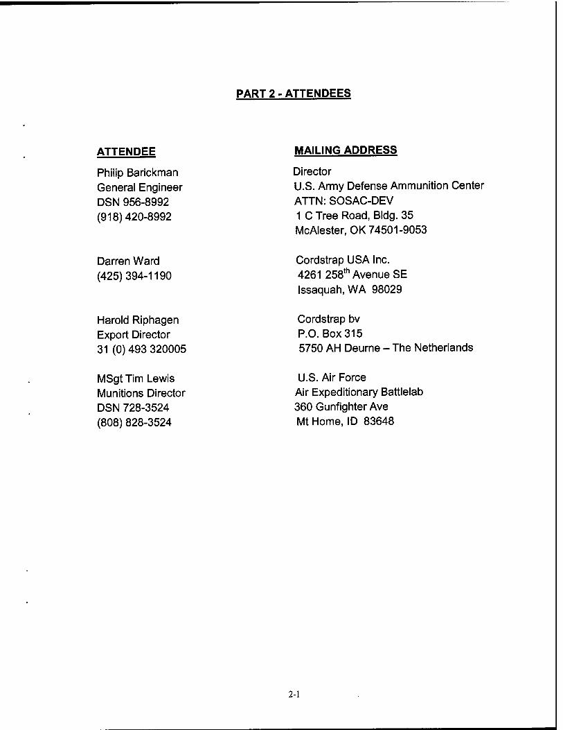
PART 2 - ATTENDEES
ATTENDEE
Philip Barickman General Engineer DSN 956-8992 (918)420-8992
MAILING ADDRESS
Director U.S. Army Defense Ammunition Center ATTN: SOSAC-DEV 1 C Tree Road, Bldg. 35 McAlester, OK 74501-9053
Darren Ward (425)394-1190
Cordstrap USA Inc. 4261 258th Avenue SE Issaquah, WA 98029
Harold Riphagen Export Director 31 (0) 493 320005
Cordstrap bv P.O. Box 315 5750 AH Deurne - The Netherlands
MSgt Tim Lewis Munitions Director DSN 728-3524 (808) 828-3524
U.S. Air Force Air Expeditionary Battlelab 360 Gunfighter Ave Mt Home, ID 83648
2-1
PART 3 - TEST EQUIPMENT
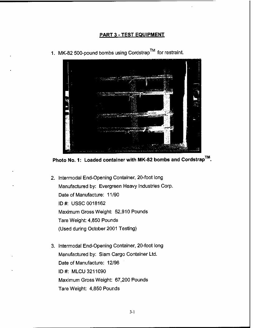
1. MK-82 500-pound bombs using Cordstrap™ for restraint.
Photo No. 1: Loaded container with MK-82 bombs and Cordstrap™.
2. Intermodal End-Opening Container, 20-foot long
Manufactured by: Evergreen Heavy Industries Corp.
Date of Manufacture: 11/90
ID#: USSC 0018162
Maximum Gross Weight: 52,910 Pounds
Tare Weight: 4,850 Pounds
(Used during October 2001 Testing)
3. Intermodal End-Opening Container, 20-foot long
Manufactured by: Siam Cargo Container Ltd.
Date of Manufacture: 12/96
ID#: MLCU 3211090
Maximum Gross Weight: 67,200 Pounds
Tare Weight: 4,850 Pounds
3-1
(Used during January 2002 Testing)
4. Truck, Tractor
5-Ton, 6X6
Model #: M931 A2 wo/winch
Manufactured by: BMY - Division of HARSCO
ID#: 31 021 89
NSN: 2320 01 230 0302
Weight: 20,100 pounds
5. Semitrailer, Flatbed, Breakbulk/Container Transporter, 22.5 Ton
Model #: M871
Manufactured by Southwest Truck Body, St. Louis, MO
ID#: NX03PJ-0063
NSN: 2330 00 122 6799
Weight: 15,630 pounds
3-2
PART 4 - TEST PROCEDURES
The test procedures outlined in this section were extracted from TP-94-01,
"Transportability Testing Procedures," July 1994, for validating tactical vehicles
and outloading procedures used for shipping munitions by truck and railcar.
Inert (non-explosive) items were used to build the load. The test loads
were prepared using the blocking and bracing procedures proposed for use with
munitions (see Part 7 for procedures). The weight and physical characteristics
(weights, physical dimensions, center of gravity, etc.) of the test loads simulate
live (explosive) ammunition.
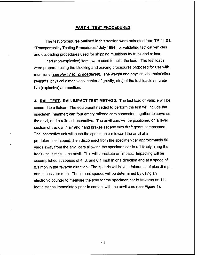
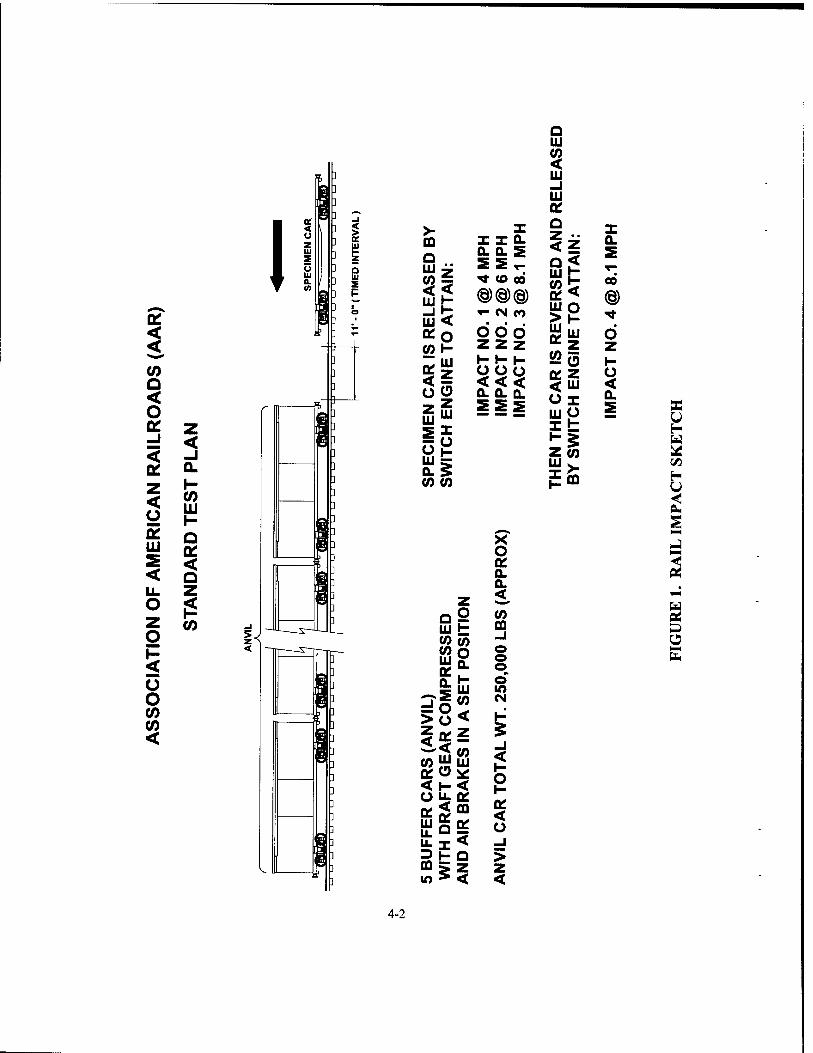
A. RAIL TEST. RAIL IMPACT TEST METHOD. The test load or vehicle will be
secured to a flatcar. The equipment needed to perform the test will include the
specimen (hammer) car, four empty railroad cars connected together to serve as
the anvil, and a railroad locomotive. The anvil cars will be positioned on a level
section of track with air and hand brakes set and with draft gears compressed.
The locomotive unit will push the specimen car toward the anvil at a
predetermined speed, then disconnect from the specimen car approximately 50
yards away from the anvil cars allowing the specimen car to roll freely along the
track until it strikes the anvil. This will constitute an impact. Impacting will be
accomplished at speeds of 4, 6, and 8.1 mph in one direction and at a speed of
8.1 mph in the reverse direction. The speeds will have a tolerance of plus .5 mph
and minus zero mph. The impact speeds will be determined by using an
electronic counter to measure the time for the specimen car to traverse an 11-
foot distance immediately prior to contact with the anvil cars (see Figure 1).
4-1
I I (0 Q < O °? 2 d <
LU Q
< Q
I M
Ü O CO CO <
] «-
I Q LU s P
>- m Q Ui 7
3g LU < *o «0 1-
So z LU
^S LJJ = Q. 5 CO CO
X III GL 0. S SSr «t to cd @@<§) i- <N tO
odd zz z I- I- I- O O ü <<< 0. 0. Q.
2 5 w = = =
ui t J2OT «0 o UI 0£ OL
i° >o
0. I- UJ CO
<
~2s o CO
Of < O
UJ u_ LL 3 DQ in
«DO
P h- Q
if
X o 0. 0- <
to CQ -I © o © o m
< I- O t-
< O _J > z <
Q LU
5 LU -I LU QC Q Z < O LU (0 K LU > LU
<
o LU
£25
< LU Ol LU O I t
0.
oo
®
d z I- o < 0.
X u
H U
2
4-2
B. ON/OFF ROAD TEST.
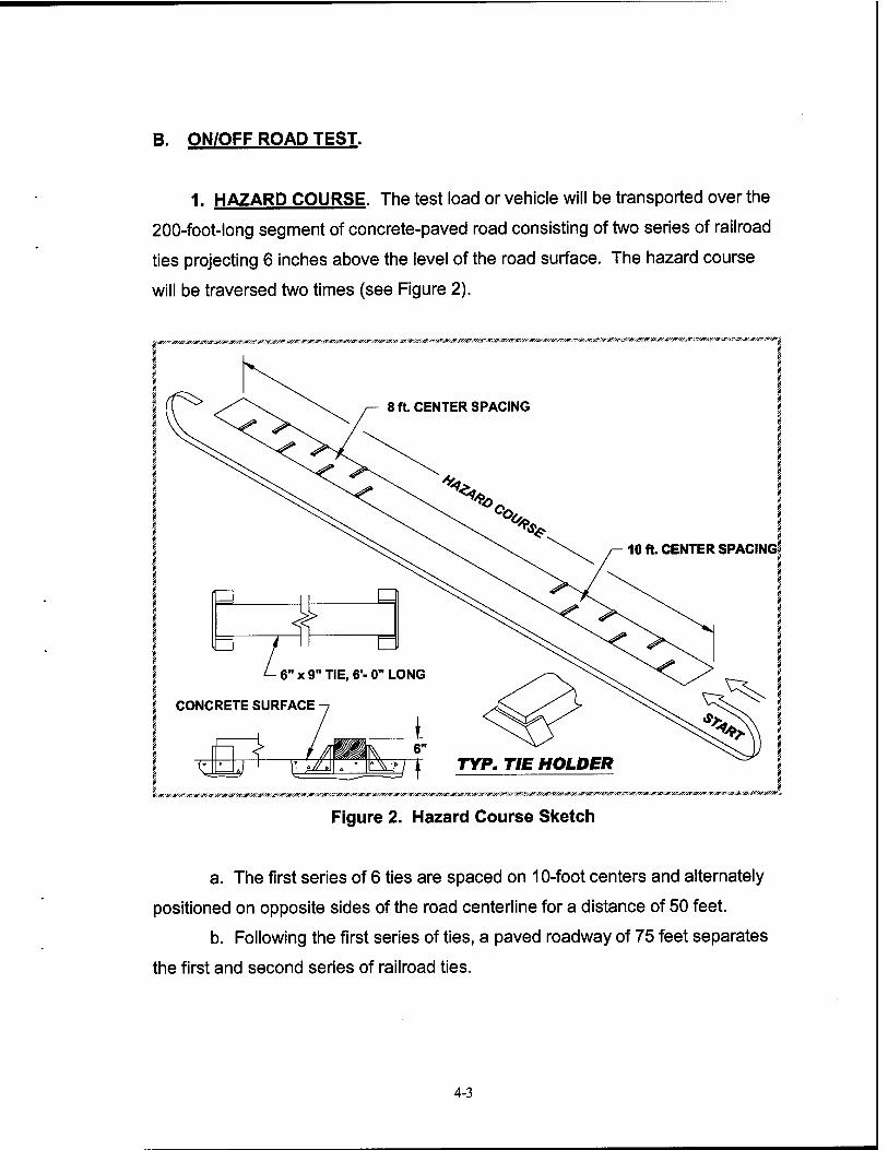
1. HAZARD COURSE. The test load or vehicle will be transported over the
200-foot-long segment of concrete-paved road consisting of two series of railroad
ties projecting 6 inches above the level of the road surface. The hazard course
will be traversed two times (see Figure 2).
■&y#/A',&A&&/Jt'jr/#>;'JF/<«'--£r/.*r.'fr-:*r/.. ■JIT^S»^»^^^«*^^
8 ft. CENTER SPACING
10 ft. CENTER SPACING!
'&/£r/&y&/&/&&/A'ijr/j7-<&/A'/*&-ip/Jt:-j&/J?/jr^^^ W/gZ'4?/jr/M'*
Figure 2. Hazard Course Sketch
a. The first series of 6 ties are spaced on 10-foot centers and alternately
positioned on opposite sides of the road centerline for a distance of 50 feet.
b. Following the first series of ties, a paved roadway of 75 feet separates
the first and second series of railroad ties.
4-3
c. The second series of 7 ties are spaced on 8-foot centers and
alternately positioned on opposite sides of the road centerline for a distance of 50
feet.
d. The test load is driven across the hazard course at speeds that will
produce the most violent vertical and side-to-side rolling reaction obtainable in
traversing the hazard course (approximately 5 mph).
2- ROAD TRIP. The test load or vehicle will be transported for a distance
of 30 miles over a combination of roads surfaced with gravel, concrete, and
asphalt. The test route will include curves, corners, railroad crossings and stops
and starts. The test load or vehicle will travel at the maximum speed for the
particular road being traversed, except as limited by legal restrictions.
3. PANIC STOPS. During the road trip, the test load or vehicle will be
subjected to three (3) full airbrake stops while traveling in the forward direction
and one in the reverse direction while traveling down a 7 percent grade. The first
three stops are at 5,10, and 15 mph while the stop in the reverse direction is
approximately 5 mph. This testing will not be required if the Rail Impact Test is
performed.
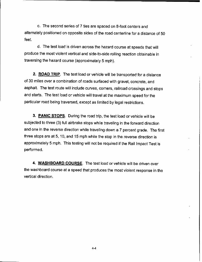
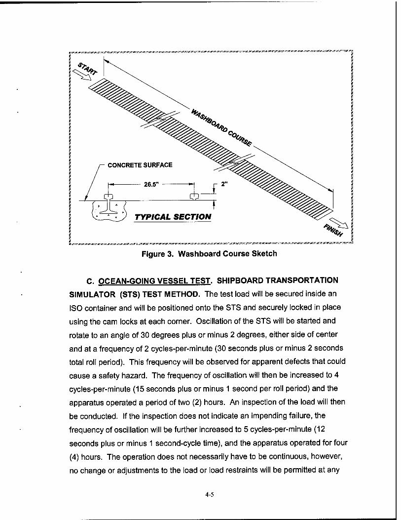
4. WASHBOARD COURSE. The test load or vehicle will be driven over
the washboard course at a speed that produces the most violent response in the
vertical direction.
4-4
rir^»5iW5«A*£«!*r;^wj*^^^i»^ £«:,«^^;W"^M?^tf-^«iP^^
ifr«^^*'*^^««W/Ä-«iBWi^^#«'iff^^^
Figure 3. Washboard Course Sketch
C. OCEAN-GOING VESSEL TEST. SHIPBOARD TRANSPORTATION
SIMULATOR (STS) TEST METHOD. The test load will be secured inside an
ISO container and will be positioned onto the STS and securely locked in place
using the cam locks at each corner. Oscillation of the STS will be started and
rotate to an angle of 30 degrees plus or minus 2 degrees, either side of center
and at a frequency of 2 cycles-per-minute (30 seconds plus or minus 2 seconds
total roll period). This frequency will be observed for apparent defects that could
cause a safety hazard. The frequency of oscillation will then be increased to 4
cycles-per-minute (15 seconds plus or minus 1 second per roll period) and the
apparatus operated a period of two (2) hours. An inspection of the load will then
be conducted. If the inspection does not indicate an impending failure, the
frequency of oscillation will be further increased to 5 cycles-per-minute (12
seconds plus or minus 1 second-cycle time), and the apparatus operated for four
(4) hours. The operation does not necessarily have to be continuous, however,
no change or adjustments to the load or load restraints will be permitted at any
4-5
time during the test. After once being set in place, the test load (specimen) will
not be removed from the apparatus until the test has been completed or is
terminated
4-6
PART 5 ■ TEST RESULTS
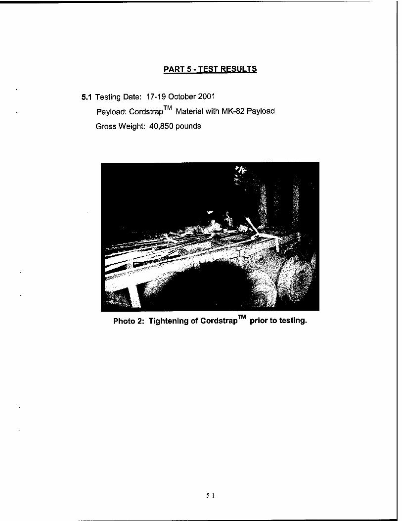
5.1 Testing Date: 17-19 October 2001
Payload: Cordstrap™ Material with MK-82 Payload
Gross Weight: 40,850 pounds
Photo 2: Tightening of Cordstrap prior to testing
5-1
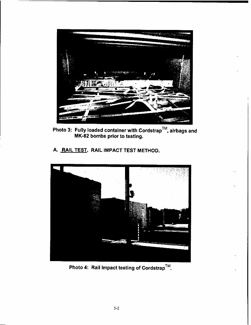
Photo 3: Fully loaded container with Cordstrap™, airbags and MK-82 bombs prior to testing.
A. RAIL TEST. RAIL IMPACT TEST METHOD.
Photo 4: Rail Impact testing of Cordstrap
5-2
Description Weight
Flatcar Number: DODX 48797
62,700 lbs.
Intermodal Container with 2,000 #GBU-31(V)1/B
36,225 lbs.
M1 Flatrack with MLRS Pods 28,265 lbs.
Intermodal container with Cordstrap™ Restraint
40,850 lbs.
Total Specimen Wt. 168,040 lbs.
Buffer Car (four cars) 1 250,000 lbs.
Figure 4
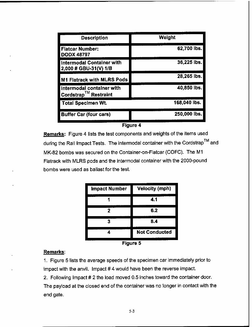
Remarks: Figure 4 lists the test components and weights of the items used
during the Rail Impact Tests. The intermodal container with the Cordstrap™ and
MK-82 bombs was secured on the Container-on-Flatcar (COFC). The M1
Flatrack with MLRS pods and the intermodal container with the 2000-pound
bombs were used as ballast for the test.
Impact Number Velocity (mph)
1 4.1
2 6.2
3 8.4
4 Not Conducted
Figure 5
Remarks:
1. Figure 5 lists the average speeds of the specimen car immediately prior to
impact with the anvil. Impact # 4 would have been the reverse impact.
2. Following Impact # 2 the load moved 0.5 inches toward the container door.
The payload at the closed end of the container was no longer in contact with the
end gate.
5-3
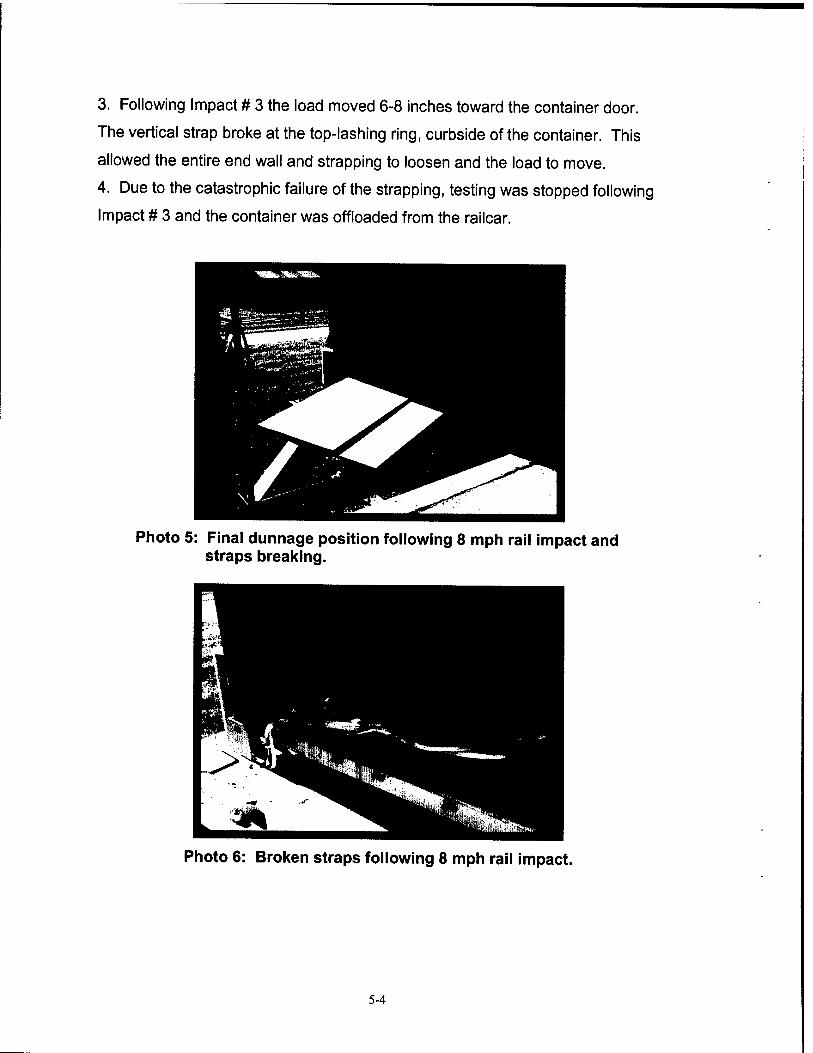
3. Following Impact # 3 the load moved 6-8 inches toward the container door.
The vertical strap broke at the top-lashing ring, curbside of the container. This
allowed the entire end wall and strapping to loosen and the load to move.
4. Due to the catastrophic failure of the strapping, testing was stopped following
Impact # 3 and the container was offloaded from the railcar.
Photo 5: Final dunnage position following 8 mph rail impact and straps breaking.
Photo 6: Broken straps following 8 mph rail impact.
5-4
Photo 7: Shifted payload following 8 mph rail impact.
In order to gain additional information the Cordstrap™ representatives were
permitted to reload the container using different strapping and the Hazard
Course, Road Trip, Washboard Course, and Shipboard Transportation Simulator
(STS) tests were conducted. The follow-on testing was for informational
purposes only.
5-5
B. ON/OFF ROAD TESTS.
1. HAZARD COURSE.
TM Photo 8: Hazard Course testing of Cordstrap and MK-82 bombs
Remarks:
Pass No. Elapsed Time Velocity (mph)
1 24 Seconds 6.1
2 26 Seconds 5.6
3 27 Seconds 5.4
4 24 Seconds 6.1
Figure 6
1. Figure 6 lists the average speeds of the test load through the Hazard Course.
2. Following Passes #2 and #4 the load was examined and no significant
movement or damage to the system was found.
3. Passes #3 and #4 were conducted following the completion of the Road Trip.
5-6
2. ROAD TRIP. Examination of the load and strapping system upon
completion of the road trip revealed that the straps across the nose end of the
bombs, at the closed end of the container, had loosened. The loosening was
caused by the straps sliding toward the nose end of the bombs.
Photo 9: Loose Cordstrap following Road Course
3. PANIC STOPS. Testing was not performed since earlier load had
already demonstrated poor longitudinal restraint of Cordstrap™ material during
rail impact test.
5-7
4. WASHBOARD COURSE.
Photo 10: Washboard Course testing of Cordstrap with MK-82 bombs
Remarks:
1. The straps across the nose ends of the bombs at the closed end of the
container slipped completely off of the bombs.
2. The load moved 0.5 inches toward the driver's side of the container and
0.125 inches toward the closed end of the container.
C. OCEAN-GOING VESSEL. SHIPBOARD TRANSPORTATION SIMULATOR
(STS) TEST METHOD.
Photo 11: Shipboard Transportation Simulator testing of Cordstrap with MK-82 bombs.
TM
TM
Remarks:
1. The intermodal container with the Cordstrap "Vl and MK-82 bombs were
removed from the trailer and positioned onto the STS.
2. During testing the load moved 1 inch in each direction (left and right). The
total movement was 2 inches.
3. The center pallet, on the driver's side, shifted during testing. The pallet
shifted away from the container wall 0.25 inches at the base of the bomb to 1
inch at the nose end of the bomb.
4. The anti-slip pads between the pallets and the container floor, at the door end
of the container, wore through.
5-9
D. AIR BAG HISTORY. Air bags were used in blocking and bracing the MK-82
bomb pallets in the intermodal container. One air bag was located in the front
(closed end) of the container and one was located in the center.
Photo 12: View of front air bag.
Photo 13: View of center air bag.
5-10
During the complete testing sequence, the pressure in each air bag was
monitored. The pressures were as follows:
1 bar = 14.5 pounds/inch 2
16 October 2001, 1300 HRS
Front - 0.225 bar
Center-0.225 bar
17 October 2001, 0845 HRS
Front - 0.200 bar
Center-0.215 bar
17October2001,1100HRS
Front-0.210 bar
Center-0.220 bar
Following the 1100 hrs reading the bags were removed from the container and
deflated and destroyed. The container was then reloaded using different straps
and new air bags.
17October2001,1400HRS
Front - 0.250 bar
Center-0.25 bar
18 October 2001 - 0730 HRS
Front-0.190 bar
Center-0.210 bar
5-11
18 October 2001 - 1330 HRS
Front - 0.200 bar
Center - 0.250 bar
21 November 2001 -0900 HRS
Front-0.125 bar
Center-0.100 bar
Remarks: Air bags are not an acceptable alternative for wood blocking and
bracing. The air bags deflated over time due to changes in temperature and
pressure and would not hold the load tight. Also, air bags are susceptible to
puncture and damage.
5.2 Testing Date: 28 January 2002
Payload: Cordstrap™ Materia
Gross Weight: 40,850 pounds
Payload: Cordstrap™ Material with MK-82 Payload
.TM Photo 14: Pre-Staging of Cordstrap prior to loading container with MK-82 bombs.
5-12
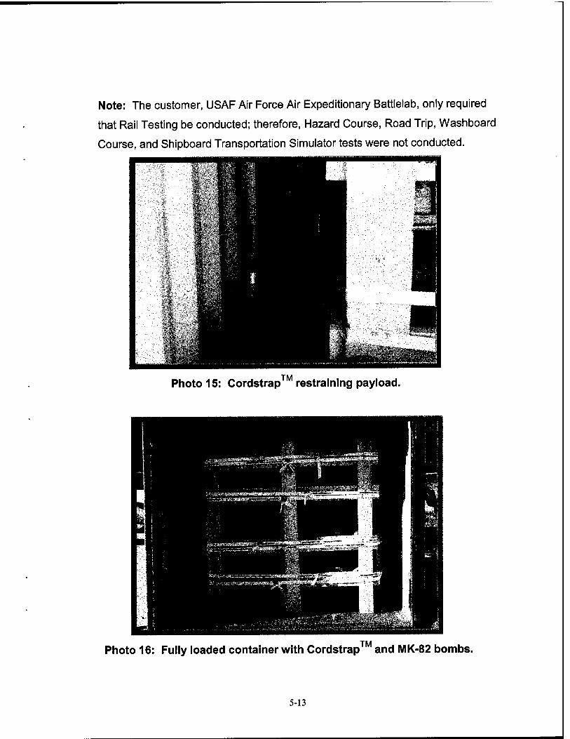
Note: The customer, USAF Air Force Air Expeditionary Battlelab, only required
that Rail Testing be conducted; therefore, Hazard Course, Road Trip, Washboard
Course, and Shipboard Transportation Simulator tests were not conducted.
Photo 15: Cordstrap restraining payload.
Photo 16: Fully loaded container with Cordstrap and MK-82 bombs.
5-13
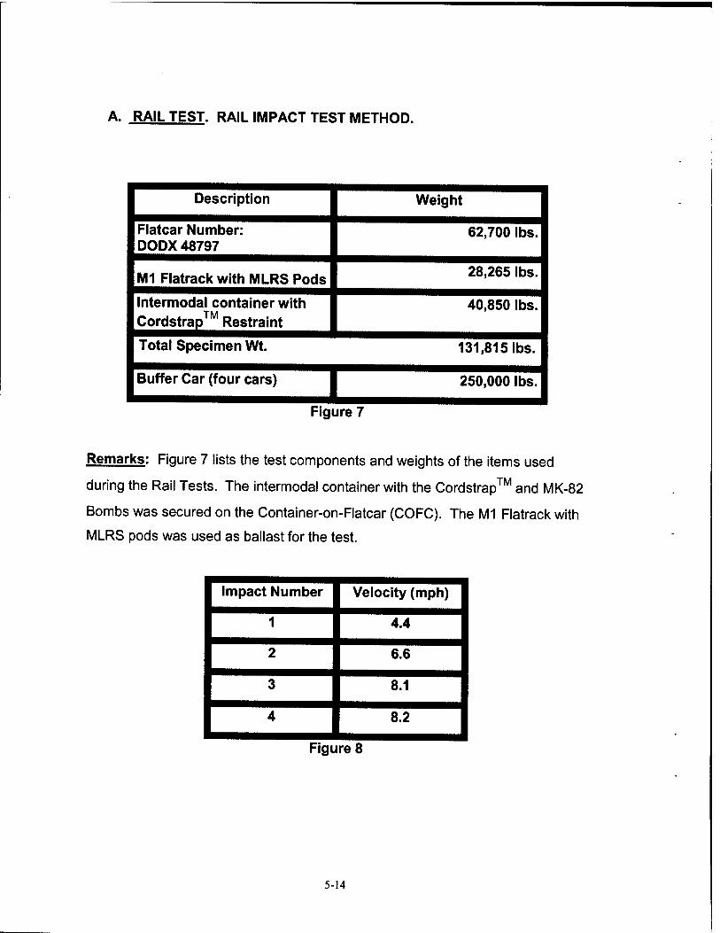
A. RAIL TEST. RAIL IMPACT TEST METHOD.
Description Weight
Flatcar Number: DODX 48797
M1 Flatrack with MLRS Pods
62,700 lbs.
28,265 lbs.
Intermodal container with Cordstrap™ Restraint
40,850 lbs.
Total Specimen Wt.
Buffer Car (four cars) I Figure 7
131,815 lbs.
250,000 lbs.
Remarks: Figure 7 lists the test components and weights of the items used
during the Rail Tests. The intermodal container with the Cordstrap™ and MK-82
Bombs was secured on the Container-on-Flatcar (COFC). The M1 Flatrack with
MLRS pods was used as ballast for the test.
Impact Number Velocity (mph)
1 4.4
2 6.6
3 8.1
4 8.2
Figure 8
5-14
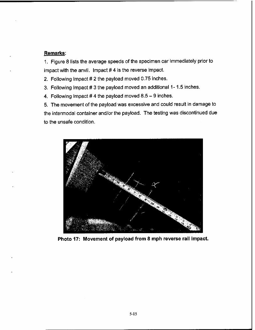
Remarks:
1. Figure 8 lists the average speeds of the specimen car immediately prior to
impact with the anvil. Impact # 4 is the reverse impact.
2. Following Impact # 2 the payload moved 0.75 inches.
3. Following Impact # 3 the payload moved an additional 1-1.5 inches.
4. Following Impact # 4 the payload moved 8.5 - 9 inches.
5. The movement of the payload was excessive and could result in damage to
the intermodal container and/or the payload. The testing was discontinued due
to the unsafe condition.
Photo 17: Movement of payload from 8 mph reverse rail impact.
5-15
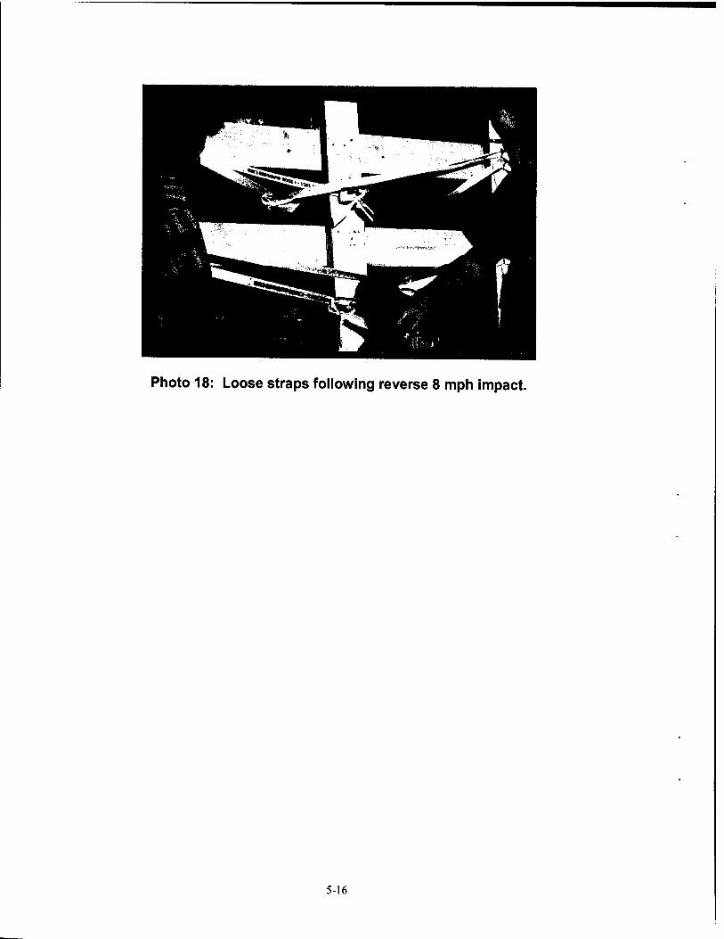
Photo 18: Loose straps following reverse 8 mph impact.
5-16
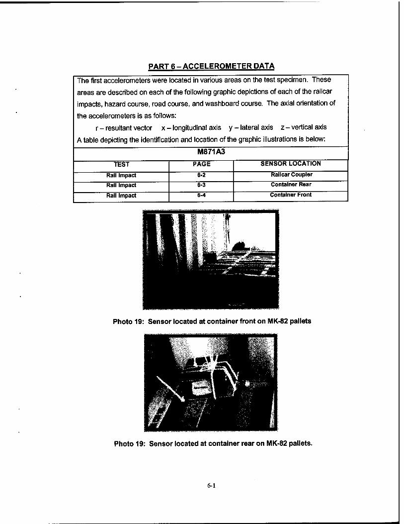
PART 6-ACCELEROMETER DATA
The first accelerometers were located in various areas on the test specimen. These
areas are described on each of the following graphic depictions of each of the railcar
impacts, hazard course, road course, and washboard course. The axial orientation of
the accelerometers is as follows:
r - resultant vector x - longitudinal axis y - lateral axis z-vertical axis
A table depicting the identification and location of the graphic illustrations is below:
M871A3
TEST PAGE SENSOR LOCATION
Rail Impact 6-2 Railcar Coupler
Rail Impact 6-3 Container Rear
Rail Impact 6-4 Container Front
Photo 19: Sensor located at container front on MK-82 pallets
Photo 19: Sensor located at container rear on MK-82 pallets.
6-1

TT
ZA-
ZA-
I VA-
ZA.
ZA-
lA-
3) ■<- CM Cpc\i ^
S 9? 3 SS £ £ & g Ö o T^csi"10 ° m <° ■ n IN csi i- d
E
E
9 *: o ö
A a (ß) uoiiBJ3|aoov (ß) uojiBjaiaoov (ß) uojiejaiaoov (ß) uouejaiaoov
6-2
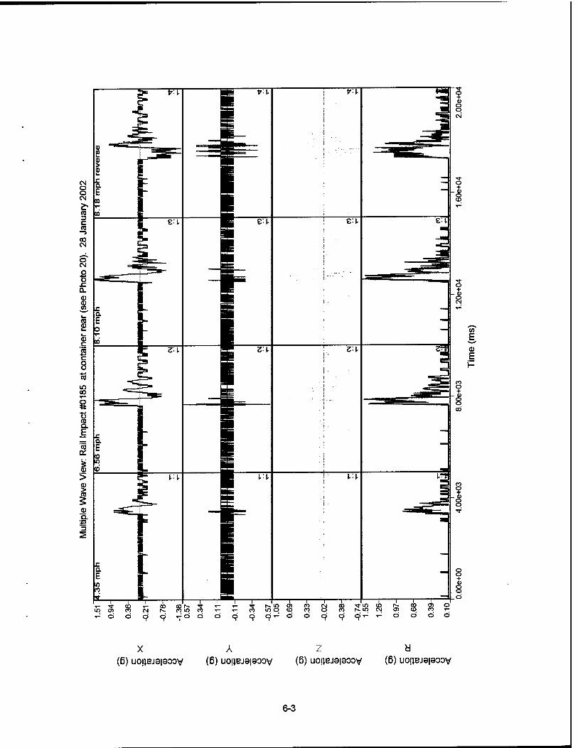
E. a> E i-
^r m to t~- SKI N 05
9 9- - d
T r CO O) o <D 00 i- Ö Ö Ö
A a (6) uo!}BJ9|900V (6) uo|iBJ8|aoov (ß) uo!iBJ9|aoov (ß) uojjBjeiaoov
6-3
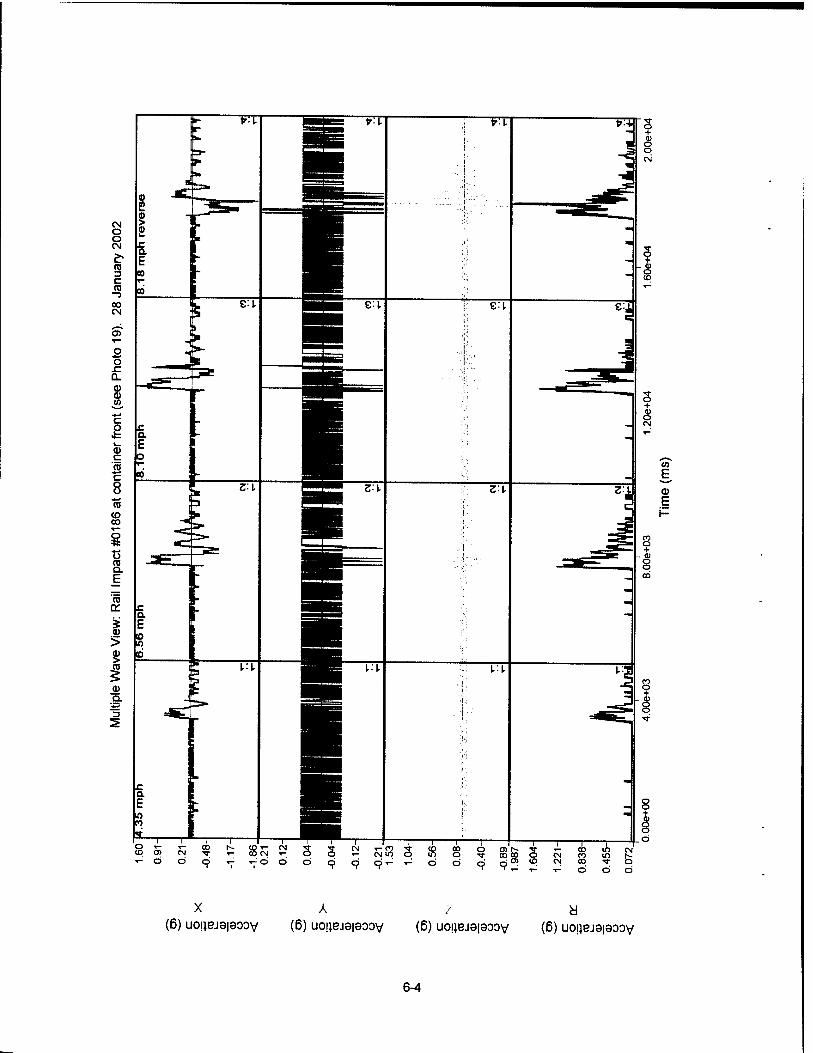
O) £- 3 r- CO ID co oo o CM co m Q 0> <0 CM CO TT
CM
o
A a (6) uo|}BJ3|9oov (ß) uoijBjaiaoov (ß) uojiejsiaoov (ß) uojjejaiaoov
6-4
PART 7-DRAWINGS
The following drawing represents the load configuration that was subjected to
the test criteria. The drawing can be accessed at:
http://www.dac.armv.mil/DET/dapam/toc.html
7-1
APPROVED BY BUREAU OF EXPLOSIVES
0A1S 7-/2-?7
LOADING AND BRACING* IN END OPENING ISO CONTAINERS OF MK82 (500 POUND) BOMBS ON MHU-149/E METAL PALLETS
INDEX
£2H PAGE(S)
TYPICAL LOADING PROCEDURES _ 5 GENERAL NOTES AND MATERIAL SPECIFICATIONS a PALLET UNIT DETAIL 2 DETAILS _ A LESS-THAN-FULL-LOAD DETAILS glfo
APPROVE). U.S. ARMY MOUSTRIAL OPERATIONS COMMAND
U.S. ARMY MATERIEL COMMAND DRAWING
APPROVED BY ORDER OF COMMANDNG GENERAL. U.S. A*MY MATER«. COMMAND
A^^i^t DEFENSE AMMUNITION CENTER
ENGINEER
TECHNICIAN
DRAFTSMAN
BASIC
REV.
BASIC
REV.
BASIC
REV.
TRANSPORTATION ENGINEERING
DIViaON
VALUATION ENGINEERING
DIVigON
LOGISTICS ENGINEERING
OFFICE 7
LAURA FIEFFER
*jLU4mi- 7>' 3i*wui Z
Ucpf. f/LtlL^
*Jt^t-
DO NOT SCALE
WEB8ITE: HTTP://WWW.DAC.ARMY.MIL
APRIL 1997
CLASS
19
DIVISION
48
DRAWING
8643
FEE
SP15PB12
PROJECT 8P 342-87
7-2
NOSE END OF PALLET UNIT.
REAR OF CONTAINER,
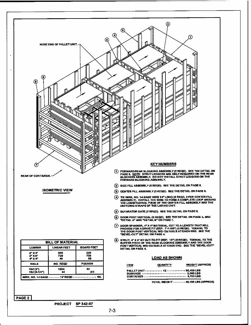
ISOMETRIC VIEW
KEYNUMBERS
FORWARD/REAR BLOCKING ASSEMBLY (2 RECtD). SEE THE DETAIL ON PAGE 6. NOTE: STRUT LEDGERS ARE ONLY REQUIRED ON THE REAR BLOCKING ASSEMBLY. DO NOT INSTALL STRUT LEDGERS ON THE FORWARD BLOCKING ASSEMBLY.
(D SIDE FILL ASSEMBLY (6 REQD). SEE THE DETAIL ON PAGE 6.
(D CENTER FILL ASSEMBLY (3 REQD). SEE THE DETAIL ON PAGE 6.
(?) TIE WIRE, NO. 14 GAGE WIRE 24' LONG (6 REQD, 2 PER CENTER FILL ASSEMBLY). INSTALL THE WIRE TO FORM A COMPLETE LOOP AROUND THE LONGITUDINAL PIECE OF THE CENTER FILL ASSEMBLY AND THE UNITIZING STRAPS OF THE LADING UNIT.
© SEPARATOR GATE (2 REQD). SEE THE DETAIL ON PAGE 5.
® DOORPOSTVERTICAL(2REQD). SEE THE DETAIL ON PAGE 4, AND -DETAIL A" AND "DETAIL B-ON PAGE 7.
BILL OF MATERIAL LUMBER UNEAR FEET BOARD FEET
2-X4" 2-X6- 4-X4"
338 729 49
226 729
66
NAILS NO. REQD POUNDS
10d(3") 12d (3-1/4")
1284 44
20 3/4
WIRE, NO. 14GAGE 12'REQD-- NIL
©
©
DOOR SPANNER, 4" X 4" MATERIAL, CUT TO A LENGTH THAT WILL PROVIDE FOR A DRIVE FIT (REF: 7M-3/8") (3 REQD). TOENAILTO THE DOOR POST VERTICAL W/2-12d NAILS AT EACH END. SEE THE "BEVEL-CUT" DETAIL ON PAGE 4.
STRUT, 4" X 4" BY CUT-TO-FIT (REF: 19") (8 REQD). TOEN AIL TO THE BUFFER PIECE OF THE REAR BLOCKING ASSEMBLY AND THE DOOR POST VERTICAL W/2-12d NAILS AT EACH END. SEE THE "BEVEL-CUT" DETAIL ON PAGE 4.
ITEM
LOAD AS SHOWN
QUANTITY WEIGHT (APPROX)
PALLETUNIT 12 36,420 LBS DUNNAGE 2.063LBS CONTAINER 4,700 LBS
TOTAL WEIGHT 43,183 LBS (APPROX)
PAGE 2 |
PROJECT SP 342-97
7-3
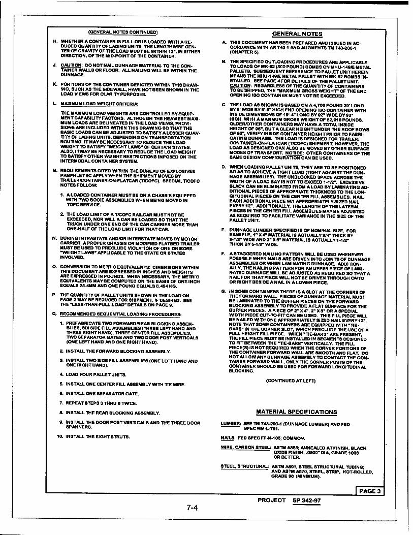
(GENERAL NOTES CONTINUED)
H. WHETHER A CONTAINER IS FULL OR IS LOADED WITH A RE- DUCED QUANTITY OF LADING UNITS, THE LENGTHWISE CEN- TER OF GRAVITY OF THE LOAD MUST8E WITHIN 12", IN EITHER DIRECTION, OF THE MID-POINT OF THE CONTAINER.
J. CAUTION: DO NOT NAIL DUNNAGE MATERIAL TO THE CON- TAINER WALLS OR FLOOR. ALL NAILING WILL BE WITHIN THE DUNNAGE.
K. PORTIONS OF THE CONTAINER DEPICTED WITHIN THIS DRAW- ING, SUCH AS THE SIDEWALL, HAVE NOT BEEN SHOWN IN THE LOAD VIEWS FOR CLARITY PURPOSES.
L. MAXIMUM LOAD WEIGHT CRITERIA:
THE MAXIMUM LOAD WEIGHTS ARE CONTROLLED BY EQUIP- MENT CAPABILITY FACTORS. ALTHOUGH THE HEAVIEST MAXI- MUM LOAD8 ARE DELINEATED IN THE LOAD VIEWS, PROVI- SIONS ARE INCLUDED WITHIN THIS DRAWING SO THAT THE BASIC LOADS CAN BE ADJUSTED TO SATISFY A LESSER QUAN- TITY OF LADING UNIT8. DEPENDING ON TRANSPORTATION ROUTING, IT MAY BE NECE8SARY TO REDUCE THE LOAD WEIGHT TO SATISFY "WEIGHT LAWS" OF CERTAIN STATES. ALSO, ITMAYBE NECES8ARYTO REDUCE THE LOAD WEIGHT TO SATISFY OTHER WEIGHTRESTRICTIONS IMPOSED ON THE INTERMODAL CONTAINER SYSTEM.
M. REQUIREMENTS CITED WITHIN THE BUREAU OF EXPLOSIVE8 PAMPHLET 6C APPLY WHEN THE SHIPMENT MOVES BY TRAILER/CONTAINER-ON-FLATCAR (T/COFC). 8PECIAL T/COFC NOTES FOLLOW:
1. A LOADED CONTAINER MUST BE ON A CHASSIS EQUIPPED WITH TWO BOGIE ASSEMBUES WHEN BEING MOVED IN TOFC SERVICE.
2. THELOADUMITOFAT/COFCRAILCARMUSTNOTBE EXCEEDED, NOR WILL A CAR BE LOADED SO THAT THE TRUCK UNDER ONE END OF THE CAR CARRIES MORE THAN ONE-HALF OF THE LOAD LIMIT FOR THAT CAR.
N. DURING INTRASTATE AND/OR INTERSTATE MOVE8 BY MOTOR CARRIER, A PROPER CHASSIS OR MODIFIED FLATBED TRAILER MUST BE USED TO PRECLUDE VIOLATION OF ONE OR MORE -WEIGHT LAWS" APPLICABLE TO THE STATE OR STATE8 INVOLVED.
O. CONVERSION TO METRIC EQUIVALENTS: DIMENSIONS WITHIN THIS DOCUMENT ARE EXPRESSED IN INCHES AND WEIGHTS ARE EXPRESSED IN POUNDS. WHEN NECE8SARY, THE METRIC EQUIVALENTS MAY BE COMPUTED ON THE BASIS OF ONE INCH EQUALS 2S.4MM AND ONE POUND EQUALS 0.464 KG.
P. THE QUANTITY OF PALLETUNITS SHOWN IN THE LOAD ON PAGE 2 MAY BE REDUCED FOR 8HIPMENT, IF DESIRED. SEE THE 1ESS-THAN-FULL-LOAD- DETAILS ON PAGE 9.
Q RECOMMENDED SEQUENTIAL LOADING PROCEDURES:
1. PREFABRICATE TWO FORWARD/REAR BLOCKING ASSEM- BUES, SIX SIDE FILL ASSEMBLIES (THREE LEFT HAND AND THREE RIGHT HAND), THREE CENTER FILL ASSEMBUES, TWO SEPARATOR GATES AND TWO DOOR P08T VERTICALS (ONE LEFT HAND AND ONE RIGHT HAND).
2. INSTALL THE FORWARD BLOCKING ASSEMBLY.
3. INSTALL TWO SIDE FILL ASSEMBLIES (ONE LEFT HAND AND ONE RIGHT HAND).
4. LOAD FOUR PALLETUNITS.
5. INSTALL ONE CENTER FILL ASSEMBLY WITH TIE WIRE.
6. INSTALL ONE SEPARATOR GATE.
7. REPEAT STEPS 3 THRU B TWICE.
8. INSTALL THE REAR BLOCKING ASSEMBLY.
0. INSTALL THE DOOR POST VERTICALS AND THE THREE DOOR SPANNERS.
10. IN8TALL THE EIGHT STRUTS.
GENERAL NOTES A. THIS DOCUMENT HAS BEEN PREPARED AND ISSUED IN AC-
CORDANCE WITH AR 740-1 AND AUGMENTS TM 743-200-1 (CHAPTER S).
B. THE SPECIFIED OUTLOADING PROCEDURES ARE APPLICABLE TO LOADS OF MK-82 (600 POUND) BOMBS ON MHU-14SJE METAL PALLETS. SUBSEQUENT REFERENCE TO PALLET UNIT HEREIN MEANS THE MHU-148/E METAL PALLET WITH MK-82 BOMBS IN- STALLED. SEE PAGE 4 FOR DETAILS OF THE PALLET UNIT. CAUTION: REGARDLESS OF THE QUANTITY OF CONTAINERS TO BE SHIPPED, THE "MAXIMUM GROSS WEIGHT OF THE END OPENING ISO CONTAINER MUST NOT BE EXCEEDED.
C. THE LOAD AS SHOWN IS BASED ON A 4,700 POUND 20" LONG BY 8- WIDE BY ff-6" HIGH END OPENING ISO CONTAINER WITH IN8IDE DIMENSIONS OF 19"-4" LONG BY 92" WIDE BY 93" HIGH, WITH A MAXIMUM GROSS WEIGHT OF 62,910 POUNDS. OLDER/OTHER CONTAINERS MAY HAVE A TOTAL INSIDE HEIGHT OF 95-, BUT A CLEAR HEIGHT UNDER THE ROOF BOWS OF 93", VERIFY INSIDE CONTAINER HEIGHTPRIOR TO FABRI- CATING DUNNAGE. THE LOAD IS DESIGNED FOR TRAILER/ CONTAINER-ON-FLATCAR (T/COFC) SHIPMENT, HOWEVER, THE LOAD AS DESIGNED CAN ALSO BE MOVED BY OTHER SURFACE MOOES OF TRANSPORT. NOTICE: OTHER CONTAINERS OF THE SAME DE8IQN CONFIGURATION CAN BE USED.
D. WHEN LOADING PALLETUNITS, THEY ARE TO BE POSITIONED SO AS TO ACHIEVE A TIGHT LOAD (TIGHT AGAINST THE DUN- NAGE ASSEMBUES). THE UNBLOCKED SPACE ACROSS THE WIDTH OF A LOAD BAY IS NOT TO EXCEED 1-1/2". EXCESSIVE SLACK CAN BE EUMINATED FROM A LOAD BY LAMINATING AD- DITIONAL PIECES OF APPROPRIATE THICKNESS TO THE LON- GITUDINAL PIECES ON THE CENTER FILL ASSEMBLIES. NAIL EACH ADDITIONAL PIECE W/1 APPROPRIATELY SIZED NAIL EVERY12-. ADDITIONALLY, THE LENGTH OF THE LATERAL PIECES IN THE CENTER FILL ASSEMBUES MAY BE ADJUSTED AS REQUIRED TO FACILITATE VARIANCE IN THE SIZE OF THE PALLET UNIT.
E. DUNNAGE LUMBER SPECIFIED IS OF NOMINAL SIZE. FOR EXAMPLE, 1" X 4" MATERIAL 18 ACTUALLY 3/4" THICK BY 8-1/2" WIDE AND 2" X 8" MATERIAL IS ACTUALLY 1-1/2" THICK BY 6-1/2" WIDE.
F. A STAGGERED NAILING PATTERN WILL BE USED WHENEVER PO88IBLE WHEN NAILS ARE DRIVEN INTO JOINTS OF DUNNAGE AS8EMBUES OR WHEN LAMINATING DUNNAGE. ADDITION- ALLY, THE NAILING PATTERN FOR AN UPPER PIECE OF LAMI- NATED DUNNAGE WILL BE ADJUSTED AS REQUIRED SO THAT A NAIL FOR THAT PIECE WILL NOT BE DRIVEN THROUGH ONTO OR RIGHT BESIDE A NAIL IN A LOWER PIECE.
G. IN 80ME CONTAINERS THERE IS A SLOT AT THE CORNERS OF THE FORWARD WALL. PIECES OF DUNNAGE MATERIAL MU8T BE LAMINATED TO THE BUFFER PIECES ON THE FORWARD BLOCKING ASSEMBLY TO PROVIDE A FLAT SURFACE FOR THE BUFFER PIECES. A PIECE OF 2" X 4", 2" X 3" OR A SPECIAL WIDTH PIECE CUT-TO-FIT CAN BE USED. THIS FILL PIECE WILL BE NAILED WITH ONE APPROPRIATELY SIZED NAIL EVERY 12". NOTE THAT SOME CONTAINERS ARE EQUIPPED WITH "TIE- BARS- IN THE CORNER SLOT, WHICH PRECLUDE THE USE OF A FULL HEIGHT FILL PIECE. WHEN "TIE-BARS" ARE PRESENT, THE FILL PIECE MUST BE INSTALLED IN SEGMENTS DESIGNED TO FIT BETWEEN THE "TIE-BARS" VERTICALLY. THE FILL PIECE(S) IS NOT REQUIRED WHEN THE CORNER PORTIONS OF THE CONTAINER FORWARD WALL ARE SMOOTH AND FLAT. DO NOT ALLOW ANY DUNNAGE A8SEMBLY TO CONTACT THE CON- TAINER FORWARD WALL, ONLY THE CORNER P08T8 OF THE CONTAINER SHOULD BE USED FOR FORWARD LONGITUDINAL BLOCKING.
(CONTINUED ATLEFT)
MATERIAL SPECIFICATIONS
LUMBER: SEE TM 743-200-1 (DUNNAGE LUMBER) AND FED 8PECMM-L-751.
NAIL8: FED SPEC FF-N-106; COMMON.
WIRE, CARBON STEEL: ASTM A863; ANNEALED ATF1NISH, BLACK OXIDE FINISH, .0800" DIA, GRADE 1006 OR BETTER.
STEEL, STRUCTURAL: ASTM A501, STEEL STRUCTURAL TUBING; AND ASTM A670, STEEL, STRIP, HOT-ROLLED, GRADE 36 (MINIMUM).
7-4
PAGE 3 PROJECT SP 342-97
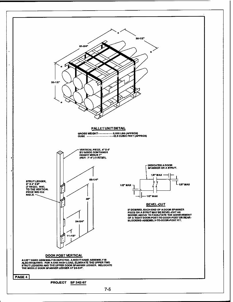
33-1/2'
PALLET UNIT DETAIL GROSS WEIGHT 3,035 LB8 (APPROX) CUBE 42.5 CUBIC FEET (APPROX)
STRUT LEDGER, 2-X4-X8" (7 REQD). NAIL TO THE VERTICAL PIECE W/2-10d NAILS.
58-1/4"
VERTICAL PIECE, 4" X 4" BY INSIDE CONTAINER HEIGHT MINUS 1" (REF: 7"-4") (1 REQD).
-INDICATES A DOOR SPANNER OR A STRUT.
1/2" MAX 1/2" MAX
BEVEL-CUT IF DESIRED, EACH END OF A DOOR SPANNER PIECE OR A STRUT MAY BE BEVEL-CUT AS SHOWN ABOVE TO FACILITATE THE ACHIEVEMENT OF A TIGHT DOOR-POST-TO-DOOR-POST OR REAR- BLOCKING-ASSEMBLY-TO-DOOR-POST FIT.
DOOR POST VERTICAL A LEFT HAND ASSEMBLY IS DEPICTED, A RIGHT HAND ASSEMBLY IS ALSO REQUIRED. FOR A ONE HIGH LOAD, ELIMINATE THE UPPER TWO STRUT LEDGERS AND THE UPPER DOOR SPANNER LEDGER. RELOCATE THE MIDDLE DOOR SPANNER LEDGER AT 24-3/4".
PAGE 4
PROJECT SP 342-97
7-5
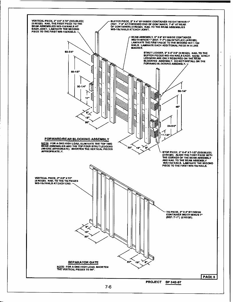
VERTICAL PIECE, 2" X 8" X 70" (DOUBLED) (8REQD). NAIL THE FIRST PIECE TO THE BEAM ASSEMBLIES VW3-1M NAILS AT EACH JOINT. LAMINATE THE SECOND PIECE TO THE FIRST W/3-10d NAIL8.
63-3/4"
- BUFFER PIECE, 2" X4" BY INSIDE CONTAINER HEIQHTMINUS1" (REF: T-*- AT FORWARD END OF CONTAINER, 7*-8" ATREAR OF CONTAINER) (2 REQD). NAIL TO THE BEAM ASSEMBUES W/3-10d NAILS AT EACH JOINT.
BEAM ASSEMBLY, 2" X 6" BY INSIDE CONTAINER WIDTH MINU8 1" (REF: T-7") (QUINTUPLED) (4REQD). LAMINATE THE FIRST PIECE TO THE SECOND W/11-10d NAIL8. LAMINATE EACH ADDITIONAL PIECE IN A LIKE MANNER.
STRUT LEDGER, 2" X 4" X 6" (8 REQD). NAIL TO THE BUFFER PIECES W/2-1M NAILS EACH. NOTE: STRUT LEDGERS ARE ONLY REQUIRED ON THEREÄR BLOCKING ASSEMBLY. DO NOT INSTALL ON THE FORWARD BLOCKING ASSEMBLY.
FORWARD/REAR BLOCKING ASSEMBLY NOTE: FOR A ONE HIGH LOAD, ELIMINATE THE TOP TWO BEAM ASSEMBLIES AND THE TOP FOUR STRUTLEDGERS (WHERE APPRORIATE). SHORTEN THE VERTICAL PIECES APPROPRIATELY.
VERTICAL PIECE, 2" X 6" X 72" (6 REQD). NAIL TO THE TIE PIECES W/3-1 Od NAILS AT EACH END
8TOP PIECE, 2" X 4" X 7-1«" (DOUBLED) (2 REQD). ALIGN THE FIRST PIECE WITH THE CORNER OF THE BEAM ASSEMBLY AND NAIL TO THE BEAM ASSEMBLY W/3-1 Od NAILS. LAMINATE THE SECOND PIECE TO THE FIRST W/3-1CW NAILS.
TIE PIECE, 2" X 4" BY INSIDE CONTAINER WIDTH MINUS 1" (REF: 7"-7-) (2 REQD).
SEPARATOR GATE NOTE: FOR A ONE HIGH LOAD, SHORTEN THE VERTICAL PIECES TO 38".
J7ÄGE5] PROJECT SP 342-97
7-6
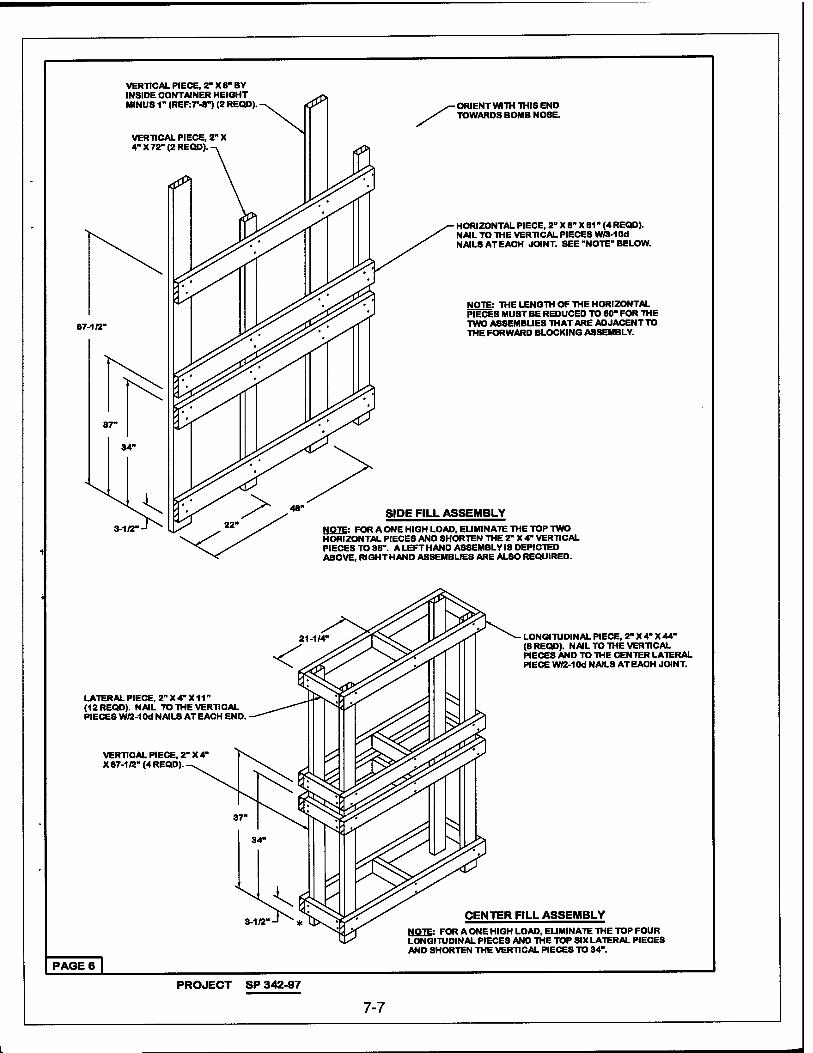
VERTICAL PIECE, 2" X 6" BY INSIDE CONTAINER HEIGHT MINUS 1- (REF:7'-8") (2 REQD).
VERTICAL PIECE, 2" X 4" X 72" (2 REQD).
ORIENT WITH THIS END TOWARDS BOMB NOSE.
67-1/2'
HORIZONTAL PIECE, 2" X 6" X 61" (4 REQD). NAIL TO THE VERTICAL PIECES W/3-10d NAILS AT EACH JOINT. SEE "NOTE" BELOW.
NOTE: THE LENGTH OF THE HORIZONTAL PIECES MUST BE REDUCED TO 60" FOR THE TWO ASSEMBLIES THAT ARE ADJACENT TO THE FORWARD BLOCKING ASSEMBLY.
ASSEMBLY NOTE: FOR A ONE HIGH LOAD, ELIMINATE THE TOP TWO HORIZONTAL PIECES AND SHORTEN THE 2- X 4" VERTICAL PIECES TO 36". A LEFT HAND ASSEMBLY IS DEPICTED ABOVE, RIGHTHAND ASSEMBLIES ARE ALSO REQUIRED.
LATERAL PIECE, 2" X 4" X11" (12 REQD). NAIL TO THE VERTICAL PIECE3 W/2-1 Od NAILS AT EACH END.
VERTICAL PIECE, 2" X 41
X 67-1/2" (4 REQD).
LONGITUDINAL PIECE, 2" X 4" X 44" (8 REQD). NAIL TO THE VERTICAL PIECES AND TO THE CENTER LATERAL PIECE W/2-1 Od NAILS AT EACH JOINT.
CENTER FILL ASSEMBLY NOTE: FOR A ONE HIGH LOAD, ELIMINATE THE TOP FOUR LONGITUDINAL PIECES AND THE TOP SIX LATERAL PIECES AND SHORTEN THE VERTICAL PIECES TO 34".
PAGE 6 |
PROJECT SP 342-97
7-7
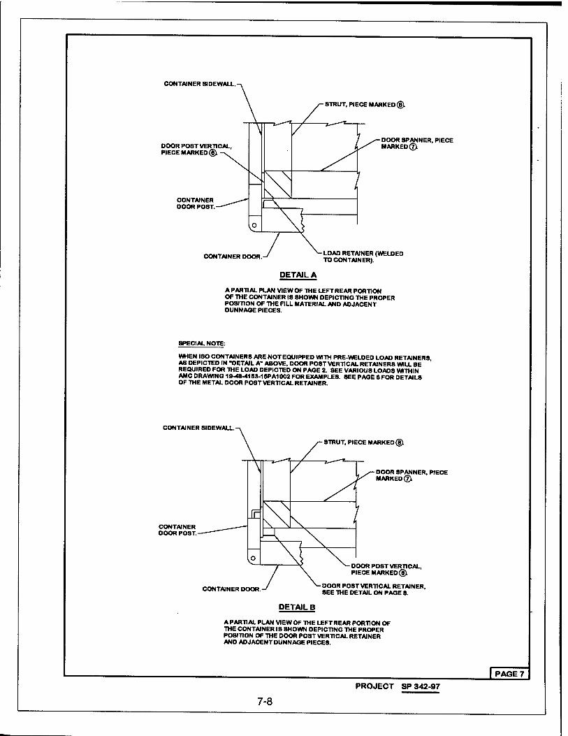
CONTAINER 8IDEWALL
STRUT, PIECE MARKED ®L
DOOR P08T VERTICAL, PIECE MARKED®:
CONTAINER DOOR POST.
DOOR SPANNER, PIECE MARKED©
CONTAINER DOOR LOAD RETAINER (WELDED TO CONTAINER).
DETAIL A
A PARTI AL PLAN VIE W OF THE LEFT REAR PORTION OF THE CONTAINER 18 SHOWN DEPICTING THE PROPER POSITION OF THE FILL MATERIAL AND ADJACENT DUNNAGE PIECES.
SPECIAL NOTE:
WHEN ISO CONTAINERS ARE NOT EQUIPPED WITH PRE-WELDED LOAD RETAINERS, AS DEPICTED IN "DETAIL A" ABOVE, DOOR POST VERTICAL RETAINERS WILL BE REQUIRED FOR THE LOAD DEPICTED ON PAGE 2. SEE VARIOUS LOADS WITHIN AMC DRAWING 19-48-4153-18PA1002 FOR EXAMPLES. SEE PAGE 8FOR DETAIL8 OF THE METAL DOOR P08T VERTICAL RETAINER.
CONTAINER SIDEWALL.
STRUT, PIECE MARKED®.
CONTAINER DOOR POST.
DOOR SPANNER, PIECE MARKED@i
CONTAINER DOOR.
DOOR POST VERTICAL, PIECE MARKED®.
DOOR POST VERTICAL RETAINER, SEE THE DETAIL ON PAGE 8.
DETAIL B
A PARTIAL PLAN VIEW OF THE LEFT REAR PORTION OF THE CONTAINER IS SHOWN DEPICTING THE PROPER POSITION OF THE DOOR POST VERTICAL RETAINER AND ADJACENT DUNNAGE PIECE8.
| PAGE 7
PROJECT SP 342-97
7-8
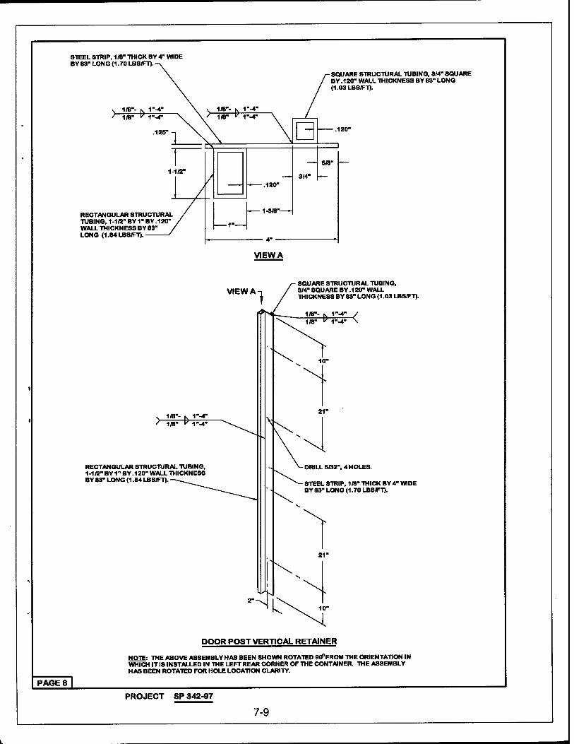
STEEL STRIP, 1/8" THICK BY 4" WIDE BY S3- LONG (1.70 LBS/FT).
SQUARE STRUCTURAL TUBING, 3/4" SQUARE BY .120" WALL THICKNESS BY 83" LONG (1.03 LBS/FT).
RECTANGULAR STRUCTURAL TUBING, 1-1/2" BY 1" BY .120" WALL THICKNESS BY 83" LONG (1.84 LBS/FT).
VIEW A
VIEW A ■ SQUARE STRUCTURAL TUBING, 3/4" SQUARE BY .120" WALL THICKNESS BY 83" LONG (1.03 LBS/FT).
" 1"-4" \
1(8"- 1/8"
RECTANGULAR STRUCTURAL TUBING, 1 -1 /2" BY 1" BY .120" WALL THICKNESS BY 83" LONG (1.84 LBS/FT).
DRILL 5/32", 4 HOLES.
STEEL STRIP, 11B" THICK BY 4" WIDE BY 83" LONG (1.70 LBS/FT).
DOOR POST VERTICAL RETAINER
NOTE: THE ABOVE ASSEMBLY HAS BEEN SHOWN ROTATED 90°FROM THE ORIENTATION IN WHICH IT IS INSTALLED IN THE LEFT REAR CORNER OF THE CONTAINER. THE ASSEMBLY HAS BEEN ROTATED FOR HOLE LOCATION CLARITY.
PAGE 8 |
PROJECT SP 342-97
7-9
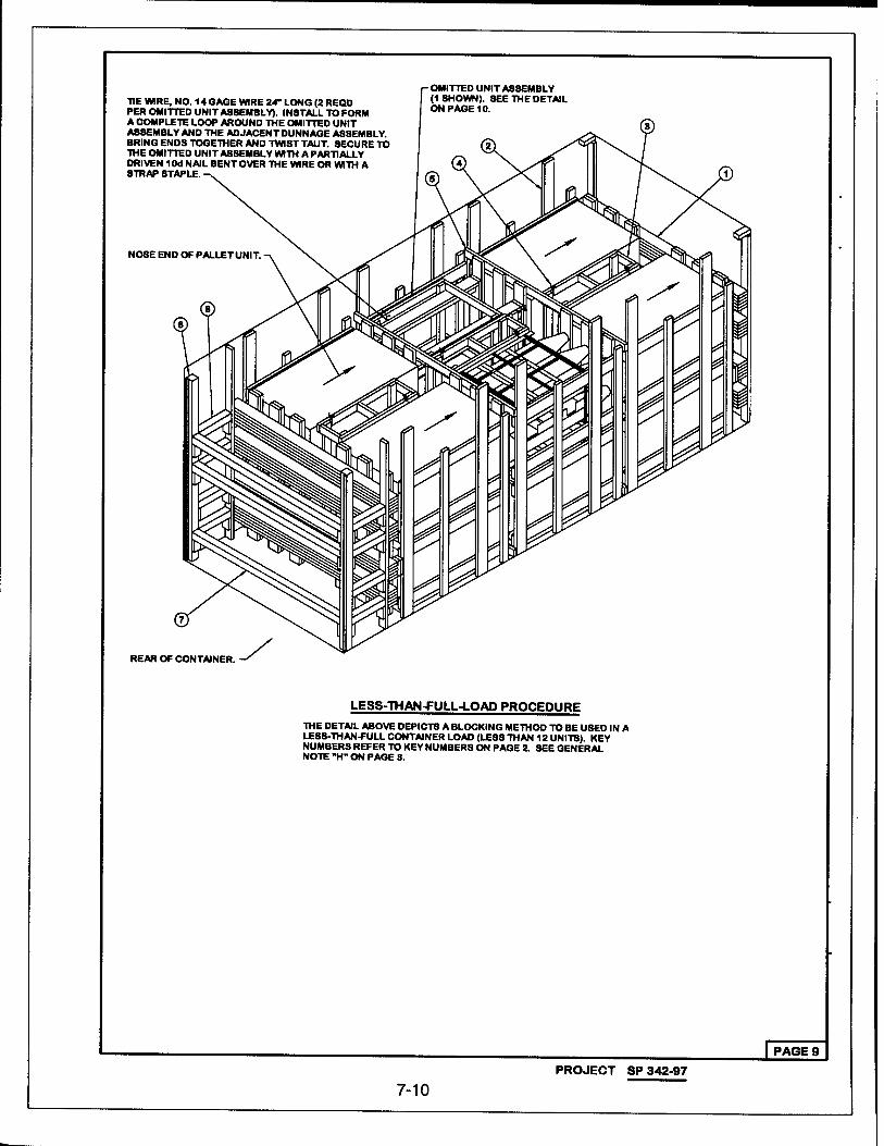
TIE WIRE, NO. 14 GAGE WIRE 24" LONG (2 REQD PER OMITTED UNIT A88EMBLV). INSTALL TO FORM A COMPLETE LOOP AROUND THE OMITTED UNIT ASSEMBLY AND THE ADJACENT DUNNAGE ASSEMBLY. BRING ENDS TOGETHER AND TWISTTAUT. SECURE TO THE OMITTED UNIT ASSEMBLY WITH A PARTIALLY DRIVEN 10d NAIL BENT OVER THE WIRE OR WITH A STRAP STAPLE.
OMITTED UNIT ASSEMBLY (1 SHOWN). SEE THE DETAIL ON PAGE 10.
NOSE END OFPALLETUNIT.
REAR OF CONTAINER
LESS-THAN-f ULL-LOAD PROCEDURE THE DETAIL ABOVE DEPICTS A BLOCKING METHOD TO BE USED IN A LE8S-THAN-FULL CONTAINER LOAD (LE88 THAN 12 UNITS). KEY NUMBERS REFER TO KEY NUMBERS ON PAGE 2. SEE GENERAL NOTE -H" ON PAGE 3.
IPAGE 9 PROJECT SP 342-97
7-10
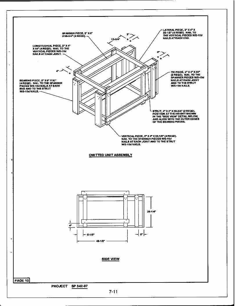
SPANNER PIECE, 2" X 6' X 58-3/4" (4 REQD)
LONGITUDINAL PIECE, 2" X 4' X 44-(4 REQD). NAIL TO THE VERTICAL PIECES W/2-1 Od NAILS AT EACH JOINT.
BEARING PIECE, 2" X 6" X 30" (4 REQD). NAIL TO THE SPANNER PIECES W/3-10d NAIL8 AT EACH END AND TO THE STRUT W/3-10d NAILS.
LATERAL PIECE, 2" X 4" X 35-1/2" (4 REQD). NAIL TO THE VERTICAL PIECES W/2-1 Od NAILS AT EACH END.
TIE PIECE, 2" X 4" X 30" (2 REQD). NAIL TO THE SPANNER PIECES W/2-1 Od NAILS AT EACH JOINT AND TO THE STRUT W/3-10d NAILS.
STRUT, 4" X 4" X 68-3/4" (2 REQD). POSITION AT THE HEIGHT SHOWN IN THE "SIDE VIEW" DETAIL BELOW, AND ALIGN WITH THE OUTER EDGES OF THE BEARING PIECES.
VERTICAL PIECE, 2" X 4" X 33-1 /2" (4 REQD). NAIL TO THE SPANNER PIECES W/2-1 Od NAILS AT EACH JOINT AND TO THE STRUT W/3-10d NAILS.
OMITTED UNIT ASSEMBLY
I '. I
I I .• ^ 4" -I..I . ,
28-1/4"
-I I- 5-1/2"
48-1/2"
-W-
SIDE VIEW
PAGE 10
PROJECT SP 342-97
7-11
Recommended