13-Sep-2016 Prepared for – Greg MacRae – Co No.: N/A
Design of Braced Steel Frame with a
Buckling Restrained Brace (BRB) System
Greg MacRae
13-Sep-2016
Supporting Document
ENEQ 650 - Assignment 2
PARK & JOHN
Design of Braced Steel Frame with a Buckling Restrained Brace (BRB) System
Supporting Document
13-Sep-2016 Prepared for – Greg MacRae – Co No.: N/A
PARK & JOHN
Supporting Document
ENEQ 650 - Assignment 2
Client: Greg MacRae
Co No.: N/A
Prepared by
Park & John Consulting
13-Sep-2016
Park & John may or may not be certified to the latest version of ISO9001, ISO14001, AS/NZS4801 and OHSAS18001.
© Park & John Consulting (Park & John). All rights reserved.
Park & John has prepared this document for the sole use of the Client and for a specific purpose, each as expressly stated in the document. No
other party should rely on this document without the prior written consent of Park & John. Park & John undertakes no duty, nor accepts any
responsibility, to any third party who may rely upon or use this document. This document has been prepared based on the Client’s description of
its requirements and Park & John’s experience, having regard to assumptions that Park & John can reasonably be expected to make in
accordance with sound professional principles. Park & John may also have relied upon information provided by the Client and other third parties to
prepare this document, some of which may not have been verified. Subject to the above conditions, this document may be transmitted, reproduced
or disseminated only in its entirety.
Design of Braced Steel Frame with a Buckling Restrained Brace (BRB) System
Supporting Document
13-Sep-2016 Prepared for – Greg MacRae – Co No.: N/A
PARK & JOHN
Quality Information
Document Supporting Document
Ref Report Template – AECOM New Zealand Ltd.
Date 13-Sep-2016
Prepared by Jae Park, Lijin John
Reviewed by Jae Park, Lijin John
Revision History
Revision Revision
Date Details
Authorised
Name/Position Signature
A 13-Sep-2016 First Issue Jae Park
- Structural Engineer
A 13-Sep-2016 First Issue Lijin John
- Structural Engineer
Design of Braced Steel Frame with a Buckling Restrained Brace (BRB) System
Supporting Document
13-Sep-2016 Prepared for – Greg MacRae – Co No.: N/A
PARK & JOHN
Table of Contents
1.0 Notations 1 2.0 Design Assumptions 2 3.0 Design Loading 2
3.1 Gravity Load 2 3.2 Live Load 2 3.3 Earthquake Load 3
3.3.1 Seismic Weight 3 3.3.2 Horizontal Design Action Coefficient 3 3.3.3 Base Shear 5 3.3.4 Equivalent Static Force Distribution 6 3.3.5 Modal Analysis 7 3.3.6 Pushover Analysis 7
3.4 Load Combinations 7 4.0 Analysis 8
4.1 Serviceability Limit State Loading 8 4.1.1 Load Combination [G + phiQ + Es] 8
4.2 Ultimate Limit State Loading 9 4.2.1 Load Combination [G+ phi Q + Eu] 9
5.0 Design of Steel Frame 10 5.1 Beam Design 10 5.2 Column Design 10 5.3 Connection Design 11
6.0 The Welded End Slot – BRB Connection Design 12 6.1 Frame Configuration 12 6.2 BRB Steel Core Materials 13 6.3 Maximum BRB Axial Force Capacity 13 6.4 BRB Cross Sectional Dimensions 13 6.5 BRB End to Gusset Connection Weld Requirements 14 6.6 BRB Steel Core Dimensions in Joint Section 16 6.7 BRB Effective Stiffness 16 6.8 Steel Casing 17
7.0 Gusset Plate Design 18 7.1 Corner Gusset Plate 18 7.2 Middle Gusset Plate 20
8.0 Demand to Capacity Ratio (DCR) Checks 23 8.1 Steel casing buckling (DCR 1) 23 8.2 Joint region yielding (DCR-2) 23 8.3 Joint region buckling (DCR-3) 24 8.4 Gusset plate block shear failure (DCR-4) 24 8.5 Gusset plate yielding (DCR-5) 25 8.6 Gusset plate buckling (DCR-6) 25 8.7 Gusset plate strength at the connections to the beam and column (DCR-7) 26
8.7.1 Von Mises yield criterion (DCR7-1 and DCR 7-4) 26 8.7.2 Tensile rupture criteria (DCR 7-2 AND 7-5) 27 8.7.3 Shear rupture criteria (DCR-7-3AND DCR 7-6) 28
8.8 Demand to Capacity Ratio Table 29 9.0 Diaphragm design 30 10.0 Composite Beam Design 32
32 32 32 32 10.1 Beams spanning in 7.5m direction 32
10.1.1 Load calculation 32 10.1.2 Beam Properties 33
Design of Braced Steel Frame with a Buckling Restrained Brace (BRB) System
Supporting Document
13-Sep-2016 Prepared for – Greg MacRae – Co No.: N/A
PARK & JOHN
10.1.3 Fully composite shear connection 33 10.1.4 Shear stud design 35 10.1.5 Partial composite action 36 10.1.6 Beam serviceability check 38 10.1.7 Vibration checks 41
11.0 RCFT Gravity column design 43 11.1 Load calculation 43 11.2 Section analysis 43
11.2.1 Axial capacity 43 12.0 SRC seismic column design 44
12.1 Nominal compressive strength calculation 44 12.2 P-M Interaction diagram 46
13.0 Results Summary 49 13.1 Non-Composite Design 49 13.2 Composite Design 49
Design of Braced Steel Frame with a Buckling Restrained Brace (BRB) System
Supporting Document
13-Sep-2016 Prepared for – Greg MacRae – Co No.: N/A
1 PARK & JOHN
1.0 Notations
For notations used throughout this document, refer to the following documents:
- NZS 3404:1997 – Steel Structures Standard
- Buckling Restrained Brace and Connection Design Procedure by National Centre for Research on
Earthquake Engineering (NCREE), dated July 2014.
Design of Braced Steel Frame with a Buckling Restrained Brace (BRB) System
Supporting Document
13-Sep-2016 Prepared for – Greg MacRae – Co No.: N/A
2 PARK & JOHN
2.0 Design Assumptions
The design assumptions are made as per the Client’s design brief given on 26 July 2016 and the subsequent
discussions / instructions on 8 August 2016 during a meeting. Refer also to the Design Features Report by Park
& John, dated 13 August 2016.
3.0 Design Loading
3.1 Gravity Load
The weight of the structure (dead load and superimposed dead load) equivalent to a concrete floor with 210mm
uniform thickness at each storey is assumed as per the Client’s brief, including at the roof level with concrete
density of 24 𝑘𝑁
𝑚3. The floors spans one way in the east-west direction.
Gravity Load on Floor, GFLOOR = Floor Load (𝑘𝑁
𝑚2) × Floor Area (𝑚2)
GFLOOR = 5.04 𝑘𝑁
𝑚2 × 26 m × 30 m
GFLOOR = 3931 kN
Gravity Load on Frame, GFRAME = Floor Load (𝑘𝑁
𝑚2) × Tributary Area (𝑚2)
GFRAME = 5.04 𝑘𝑁
𝑚2 ×
1
2 × 6.5 m × 7.5 m
GFRAME = 123 kN (per frame column)
3.2 Live Load
Live load of 3 kPa is taken for the office building in accordance with Table 3.1 of AS/NZS 1170.1:2002.
Live Load on Floor, QFLOOR = Floor Load (𝑘𝑁
𝑚2) × Floor Area (𝑚2)
QFLOOR = 3 𝑘𝑁
𝑚2 × 26 m × 30 m
QFLOOR = 2340 kN
Live Load on Frame, QFRAME = Floor Load (𝑘𝑁
𝑚2) × Tributary Area (𝑚2)
QFRAME = 3 𝑘𝑁
𝑚2 × 1
2 × 6.5 m × 7.5 m
QFRAME = 73 kN (per frame column)
Design of Braced Steel Frame with a Buckling Restrained Brace (BRB) System
Supporting Document
13-Sep-2016 Prepared for – Greg MacRae – Co No.: N/A
3 PARK & JOHN
3.3 Earthquake Load
3.3.1 Seismic Weight
Seismic weight of the building at each level is the sum of the total dead load and the reduced live load present at
each level. The seismic weight of the building can be calculated as follows:
Seismic Weight of Floor, WSEISMIC FL = GFLOOR + 𝛹𝐸 QFLOOR
WSEISMIC FL = 3931 kN + 0.3 × 2340 kN
WSEISMIC FL = 4633 kN
Seismic Weight of Roof, WSEISMIC RF = GFLOOR + 𝛹𝐸 QROOF
WSEISMIC RF = 3931 kN + 0 × 2340 kN
WSEISMIC RF = 3931 kN
Total Seismic Weight, WSEISMIC TT = 3 × WSEISMIC FL + WSEISMIC RF
WSEISMIC TT = 3 × 4633 kN + 3931 kN
WSEISMIC TT = 17830 kN
3.3.2 Horizontal Design Action Coefficient
The horizontal design action coefficient for the building can be calculated as follows, in accordance with Clause
3.1 of NZS 1170.5:2004:
Elastic Site Spectra, C(T) = Ch(T) × Z × R × N(T,D)
, where T = 0.4 second, as per Client’s brief.
The spectral shape factor, Ch(T), for the building is selected from Table 3.1 of NZS 1170.5:2004 for the site
subsoil class defined in Clause 3.1.3 of the Standard. As per the Client’s design brief, Class C – shallow soil sites
– has been assumed. Class C is defined as sites where:
- They are not Class A, Class B or Class E sites, and
- The low amplitude natural period is less than or equal to 0.6 second, or
- Depths of soil do not exceed those listed in Table 3.2 of NZS 1170.5:2004
Hence,
Spectral Shape Factor, Ch(T) = 2.36
The hazard factor, Z, can be obtained from Table 3.3 of NZS 1170.5:2004 for the central business district in
Wellington.
Hence,
Hazard Factor, Z = 0.4
Design of Braced Steel Frame with a Buckling Restrained Brace (BRB) System
Supporting Document
13-Sep-2016 Prepared for – Greg MacRae – Co No.: N/A
4 PARK & JOHN
The return period factor for the serviceability limit state, RS, or the ultimate limit state, RU, are obtained from Table
3.5 of NZS 1170.5:2004 for the return period or probability of occurrence appropriate for the limit state under
consideration as prescribed in Table 3.3. of AS/NZS 1170.0:2002.
As the building can accommodate more than 300 people an importance level of 3 is considered for which a return
period of 1/25 years is taken for serviceability limit state and 1/1000 years return period is taken for ultimate limit
state in reference to Table 3.3 of NZS 1170.0:2002.
Hence,
Return Period Factor SLS, RS = 0.25
Return Period Factor ULS, RU = 1.3
The near fault factor for the proposed site, in reference to Clause 3.1.6 of NZS 1170.5:2004, is taken as 1.0 as
per the Client’s brief.
Hence,
Near Fault Factor, N(T,D) = 1.0
Hence, the elastic site hazard spectrum value for horizontal loading, C(T), for the building is calculated as follows:
Elastic Site Spectra SLS, C(T)SLS = Ch(T) × Z × R × N(T,D)
C(T)SLS = 2.36 × 0.4 × 0.25 × 1.0
C(T)SLS = 0.236
Elastic Site Spectra ULS, C(T)ULS = Ch(T) × Z × R × N(T,D)
C(T)ULS = 2.36 × 0.4 × 1.3 × 1.0
C(T)ULS = 1.23
Hence, the horizontal design action coefficient, CD(T1) can be calculated as follows:
Horizontal Design Action Coefficient SLS,
CD(T1) SLS = C(T)SLS
CD(T1) SLS = 0.236
Horizontal Design Action Coefficient ULS,
CD(T1) ULS = C(T)ULS × 𝑆𝑝
𝐾µ
, where the structural performance factor, SP, of the building is assumed to be 1.0, as per the Client’s brief, and 𝐾µ
is calculated assuming the structural ductility of 3.0.
Design of Braced Steel Frame with a Buckling Restrained Brace (BRB) System
Supporting Document
13-Sep-2016 Prepared for – Greg MacRae – Co No.: N/A
5 PARK & JOHN
For soil class C and for T1 < 0.7 second,
𝐾µ = (µ−1)×𝑇
0.7 + 1
𝐾µ = (3−1)×0.4
0.7 +1
𝐾µ = 2.14
Hence,
Horizontal Design Action Coefficient ULS,
CD(T1) ULS = C(T)ULS × 𝑆𝑝
𝐾µ
CD(T1) ULS = 1.23 × 1.0
2.14
CD(T1) ULS = 0.574
3.3.3 Base Shear
The horizontal seismic shear acting at the base of the structure is:
Base Shear SLS, Vb SLS = CD(T1) SLS × WSEISMIC TT
Vb SLS = 0.236 × 17830 kN
Vb SLS = 4208 kN
Base Shear ULS, Vb ULS = CD(T1) ULS × WSEISMIC TT
Vb ULS = 0.574 × 17830 kN
Vb ULS = 10234 kN
Design of Braced Steel Frame with a Buckling Restrained Brace (BRB) System
Supporting Document
13-Sep-2016 Prepared for – Greg MacRae – Co No.: N/A
6 PARK & JOHN
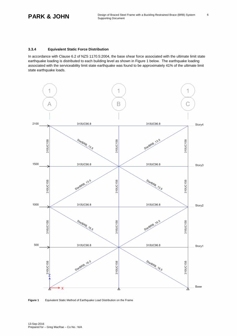
3.3.4 Equivalent Static Force Distribution
In accordance with Clause 6.2 of NZS 1170.5:2004, the base shear force associated with the ultimate limit state
earthquake loading is distributed to each building level as shown in Figure 1 below. The earthquake loading
associated with the serviceability limit state earthquake was found to be approximately 41% of the ultimate limit
state earthquake loads.
Figure 1 Equivalent Static Method of Earthquake Load Distribution on the Frame
Design of Braced Steel Frame with a Buckling Restrained Brace (BRB) System
Supporting Document
13-Sep-2016 Prepared for – Greg MacRae – Co No.: N/A
7 PARK & JOHN
3.3.5 Modal Analysis
The modal analysis in accordance with Clause 6.3 of NZS 1170.5:2004 has been performed to check the degree
of contribution of the higher mode effects to the frame design.
3.3.6 Pushover Analysis
The pushover analysis was performed, considering the non-linear properties of the buckling restrained braces and
frame columns to verify the structural ductility assumed in design.
3.4 Load Combinations
The load combinations for the serviceability limit state and the ultimate limit state, in reference to Section 4 of NZS
1170.0:2002 were considered. Table 1 below shows the summary of the load combinations considered for the
structural analysis.
Table 1 Serviceability Limit State and the Ultimate Limit State Loading Combinations Considered in Design
Serviceability Limit State Loading Combinations Ultimate Limit State Loading Combinations
G 1.35G
G + ΨsQ 1.2G + 1.5Q
G + ΨlQ G + ΨEQ + Eu
G + ΨEQ + Es -
Design of Braced Steel Frame with a Buckling Restrained Brace (BRB) System
Supporting Document
13-Sep-2016 Prepared for – Greg MacRae – Co No.: N/A
8 PARK & JOHN
4.0 Analysis
4.1 Serviceability Limit State Loading
4.1.1 Load Combination [G + phiQ + Es]
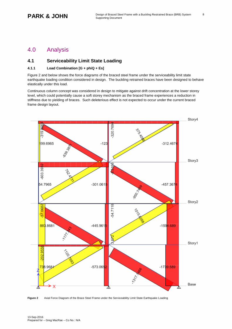
Figure 2 and below shows the force diagrams of the braced steel frame under the serviceability limit state
earthquake loading condition considered in design. The buckling retrained braces have been designed to behave
elastically under this load.
Continuous column concept was considered in design to mitigate against drift concentration at the lower storey
level, which could potentially cause a soft storey mechanism as the braced frame experiences a reduction in
stiffness due to yielding of braces. Such deleterious effect is not expected to occur under the current braced
frame design layout.
Figure 2 Axial Force Diagram of the Brace Steel Frame under the Serviceability Limit State Earthquake Loading
Design of Braced Steel Frame with a Buckling Restrained Brace (BRB) System
Supporting Document
13-Sep-2016 Prepared for – Greg MacRae – Co No.: N/A
9 PARK & JOHN
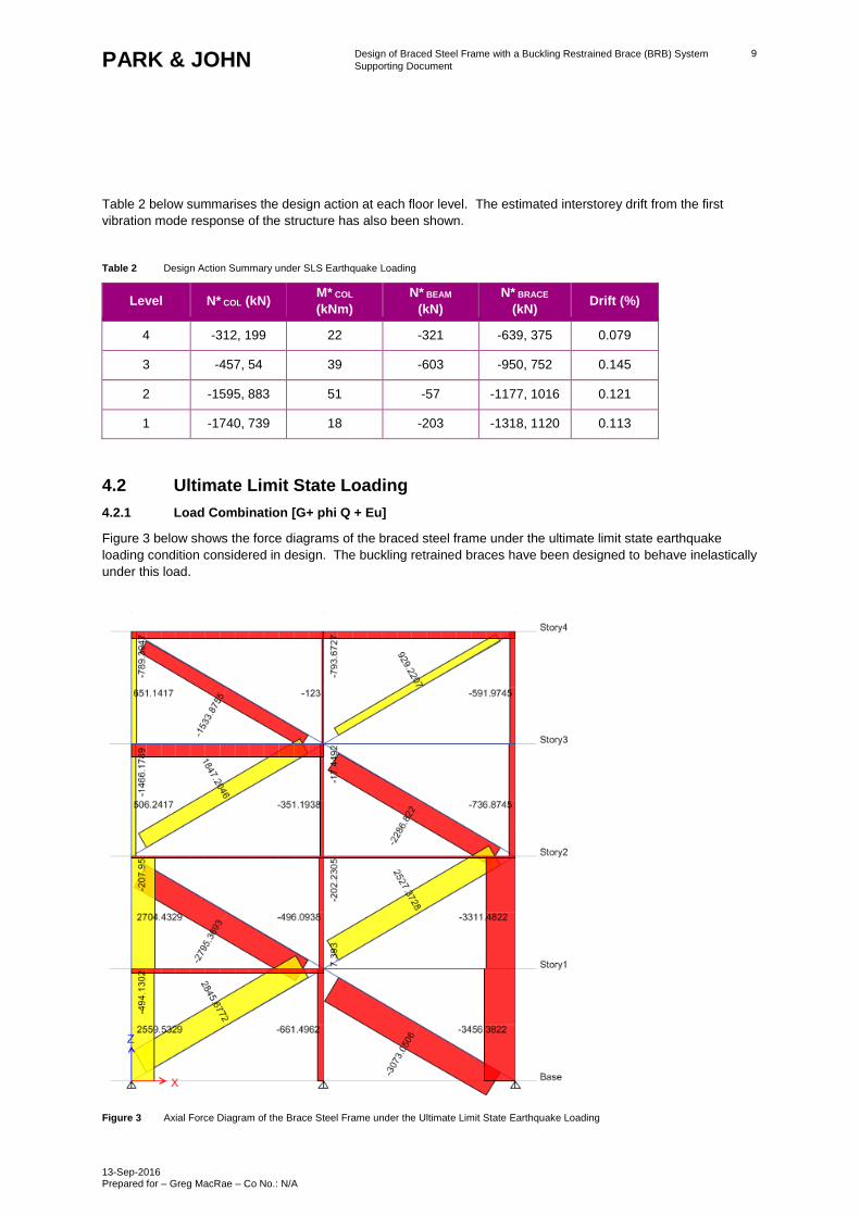
Table 2 below summarises the design action at each floor level. The estimated interstorey drift from the first
vibration mode response of the structure has also been shown.
Table 2 Design Action Summary under SLS Earthquake Loading
Level N* COL (kN) M* COL
(kNm)
N* BEAM
(kN)
N* BRACE
(kN) Drift (%)
4 -312, 199 22 -321 -639, 375 0.079
3 -457, 54 39 -603 -950, 752 0.145
2 -1595, 883 51 -57 -1177, 1016 0.121
1 -1740, 739 18 -203 -1318, 1120 0.113
4.2 Ultimate Limit State Loading
4.2.1 Load Combination [G+ phi Q + Eu]
Figure 3 below shows the force diagrams of the braced steel frame under the ultimate limit state earthquake
loading condition considered in design. The buckling retrained braces have been designed to behave inelastically
under this load.
Figure 3 Axial Force Diagram of the Brace Steel Frame under the Ultimate Limit State Earthquake Loading
Design of Braced Steel Frame with a Buckling Restrained Brace (BRB) System
Supporting Document
13-Sep-2016 Prepared for – Greg MacRae – Co No.: N/A
10 PARK & JOHN
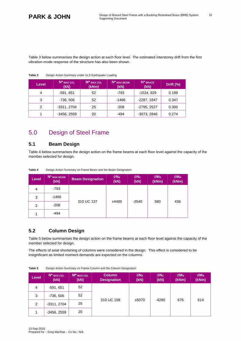
Table 3 below summarises the design action at each floor level. The estimated interstorey drift from the first
vibration mode response of the structure has also been shown.
Table 3 Design Action Summary under ULS Earthquake Loading
Level N* MAX COL
(kN)
M* MAX COL
(kNm)
N* MAX BEAM
(kN)
N* BRACE
(kN) Drift (%)
4 -591, 651 52 -793 -1534, 929 0.189
3 -736, 506 52 -1466 -2287, 1847 0.347
2 -3311, 2704 25 -208 -2795, 2527 0.300
1 -3456, 2559 20 -494 -3073, 2846 0.274
5.0 Design of Steel Frame
5.1 Beam Design
Table 4 below summarises the design action on the frame beams at each floor level against the capacity of the
member selected for design.
Table 4 Design Action Summary on Frame Beam and the Beam Designation
Level N* MAX BEAM
(kN) Beam Designation
∅NS
(kN)
∅NC
(kN)
∅MS
(kNm)
∅MN
(kNm)
4 -793
310 UC 137 ±4400 -2540 580 436 3 -1466
2 -208
1 -494
5.2 Column Design
Table 5 below summarises the design action on the frame beams at each floor level against the capacity of the
member selected for design.
The effects of axial shortening of columns were considered in the design. This effect is considered to be
insignificant as limited moment demands are expected on the columns.
Table 5 Design Action Summary on Frame Column and the Column Designation
Level N* MAX COL
(kN)
M* MAX COL
(kN)
Column
Designation
∅NS
(kN)
∅NC
(kN)
∅MS
(kNm)
∅MN
(kNm)
4 -591, 651 52
310 UC 158 ±5070 -4280 676 614 3 -736, 506 52
2 -3311, 2704 25
1 -3456, 2559 20
Design of Braced Steel Frame with a Buckling Restrained Brace (BRB) System
Supporting Document
13-Sep-2016 Prepared for – Greg MacRae – Co No.: N/A
11 PARK & JOHN
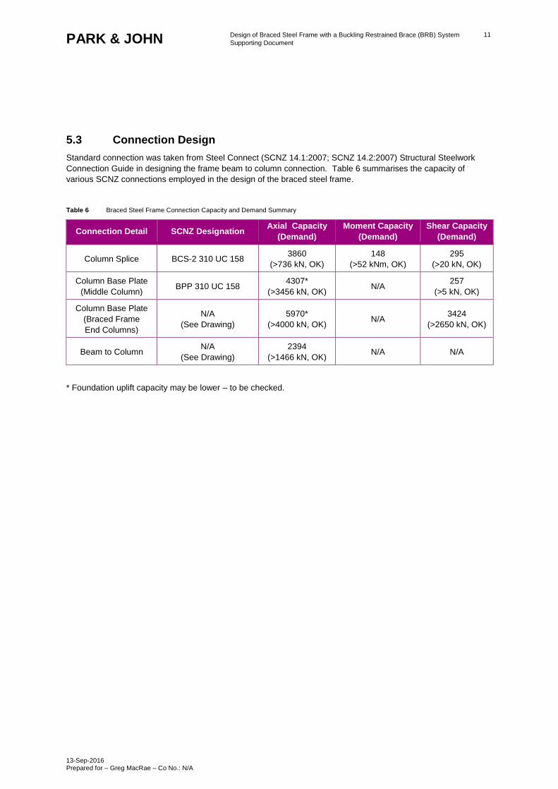
5.3 Connection Design
Standard connection was taken from Steel Connect (SCNZ 14.1:2007; SCNZ 14.2:2007) Structural Steelwork
Connection Guide in designing the frame beam to column connection. Table 6 summarises the capacity of
various SCNZ connections employed in the design of the braced steel frame.
Table 6 Braced Steel Frame Connection Capacity and Demand Summary
Connection Detail SCNZ Designation Axial Capacity
(Demand)
Moment Capacity
(Demand)
Shear Capacity
(Demand)
Column Splice BCS-2 310 UC 158 3860
(>736 kN, OK)
148
(>52 kNm, OK)
295
(>20 kN, OK)
Column Base Plate
(Middle Column) BPP 310 UC 158
4307*
(>3456 kN, OK) N/A
257
(>5 kN, OK)
Column Base Plate
(Braced Frame
End Columns)
N/A
(See Drawing)
5970*
(>4000 kN, OK) N/A
3424
(>2650 kN, OK)
Beam to Column N/A
(See Drawing)
2394
(>1466 kN, OK) N/A N/A
* Foundation uplift capacity may be lower – to be checked.
Design of Braced Steel Frame with a Buckling Restrained Brace (BRB) System
Supporting Document
13-Sep-2016 Prepared for – Greg MacRae – Co No.: N/A
12 PARK & JOHN
6.0 The Welded End Slot – BRB Connection Design
Park & John notes that, while the buckling retrained brace system design as outlined in the following pages have
been rigorously followed during the structural design, the Client’s instruction on 8 August 2016 during the project
meeting was that Park & John is to rely on the BRB manufacturer to provide the BRB system design. Park &
John notes that the manufacturer’s BRB system is to be tested for performance with the connection which Park &
John devised as one system.
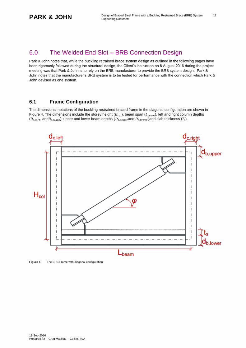
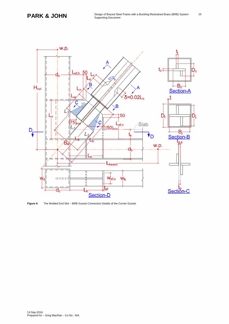
6.1 Frame Configuration
The dimensional notations of the buckling restrained braced frame in the diagonal configuration are shown in
Figure 4. The dimensions include the storey height (𝐻𝑐𝑜𝑙), beam span (𝐿𝑏𝑒𝑎𝑚), left and right column depths
(𝐷𝑐,𝑙𝑒𝑓𝑡, and𝐷𝑐,𝑟𝑖𝑔ℎ𝑡), upper and lower beam depths (𝐷𝑏,𝑢𝑝𝑝𝑒𝑟and 𝐷𝑏,𝑙𝑜𝑤𝑒𝑟)and slab thickness (𝑇𝑠).
Figure 4 The BRB Frame with diagonal configuration
Design of Braced Steel Frame with a Buckling Restrained Brace (BRB) System
Supporting Document
13-Sep-2016 Prepared for – Greg MacRae – Co No.: N/A
13 PARK & JOHN
6.2 BRB Steel Core Materials
Table 7 below lists the steel grade considered. The steel mechanical properties include the nominal yield stress (𝐹𝑦), overstrength factor (𝑅𝑦) and strain hardening factor (Ω h). The compression strength adjustment factor, Beta,
of 1.15 was considered in the design.
Table 7 The steel material and mechanical properties
Steel 𝑭𝒚 (MPa) 𝑹𝒚 Ω h β
Grade 300 300 1.25 1.05 1.15
6.3 Maximum BRB Axial Force Capacity
The cross sectional area of the BRB energy dissipation section (𝐴𝑐) can be computed according to the steel grade
and the nominal yielding strength (𝑃𝑦).
𝐴𝑐 =𝑃𝑦
𝐹𝑦
The maximum BRB compressive axial force capacity (𝑃𝑚𝑎𝑥) can be calculated as follows
𝑃𝑚𝑎𝑥 = 𝑃𝑦 × 𝑅𝑦 × 𝛺ℎ × 𝛽
The maximum BRB tensile force capacity can be computed from 𝑃𝑚𝑎𝑥
𝛽
6.4 BRB Cross Sectional Dimensions
Refer to Drawing for the WES-BRB cross sectional dimensions where, 𝑡𝑐 is the thickness of the steel core plate
perpendicular to the gusset plate, 𝐵𝑐 and 𝐷𝑐 are the cross sectional width and depth of the energy dissipation
sections, respectively. The 𝑡𝑗 is the thickness of the steel core plate parallel to the gusset plate, and Bj and Dj are
the cross sectional width and depth of the joint section, respectively. The 𝐴𝑐 , 𝐴𝑗 and 𝐴𝑡 are the cross sectional
areas of the energy dissipation section, the joint section and the transition section, respectively. The 𝐴𝑡 is the
average of 𝐴𝑐and𝐴𝑗.
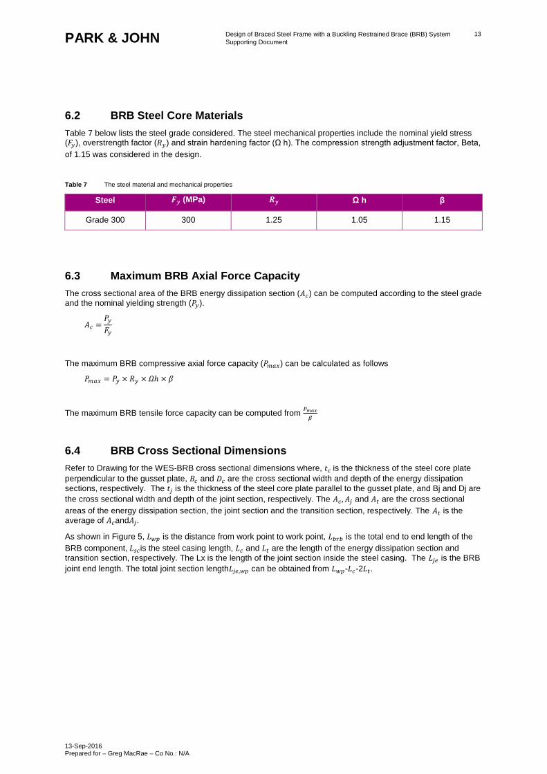
As shown in Figure 5, 𝐿𝑤𝑝 is the distance from work point to work point, 𝐿𝑏𝑟𝑏 is the total end to end length of the
BRB component, 𝐿𝑠𝑐is the steel casing length, 𝐿𝑐 and 𝐿𝑡 are the length of the energy dissipation section and
transition section, respectively. The Lx is the length of the joint section inside the steel casing. The 𝐿𝑗𝑒 is the BRB
joint end length. The total joint section length𝐿𝑗𝑒,𝑤𝑝 can be obtained from 𝐿𝑤𝑝-𝐿𝑐-2𝐿𝑡.
Design of Braced Steel Frame with a Buckling Restrained Brace (BRB) System
Supporting Document
13-Sep-2016 Prepared for – Greg MacRae – Co No.: N/A
14 PARK & JOHN
Figure 5 The Welded End Slot – BRB Component
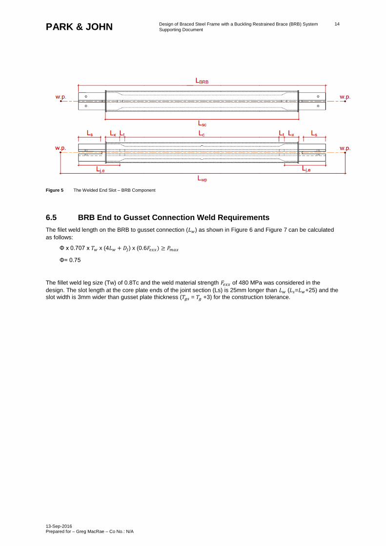
6.5 BRB End to Gusset Connection Weld Requirements
The filet weld length on the BRB to gusset connection (𝐿𝑤) as shown in Figure 6 and Figure 7 can be calculated
as follows:
Φ x 0.707 x 𝑇𝑤 x (4𝐿𝑤 + 𝐷𝐽) x (0.6𝐹𝑒𝑥𝑥) ≥ 𝑃𝑚𝑎𝑥
Φ= 0.75
The fillet weld leg size (Tw) of 0.8Tc and the weld material strength 𝐹𝑒𝑥𝑥 of 480 MPa was considered in the
design. The slot length at the core plate ends of the joint section (Ls) is 25mm longer than 𝐿𝑤 (𝐿𝑠=𝐿𝑤+25) and the
slot width is 3mm wider than gusset plate thickness (𝑇𝑔𝑠 = 𝑇𝑔 +3) for the construction tolerance.
Design of Braced Steel Frame with a Buckling Restrained Brace (BRB) System
Supporting Document
13-Sep-2016 Prepared for – Greg MacRae – Co No.: N/A
15 PARK & JOHN
Figure 6 The Welded End Slot – BRB Gusset Connection Details of the Corner Gusset
Design of Braced Steel Frame with a Buckling Restrained Brace (BRB) System
Supporting Document
13-Sep-2016 Prepared for – Greg MacRae – Co No.: N/A
16 PARK & JOHN
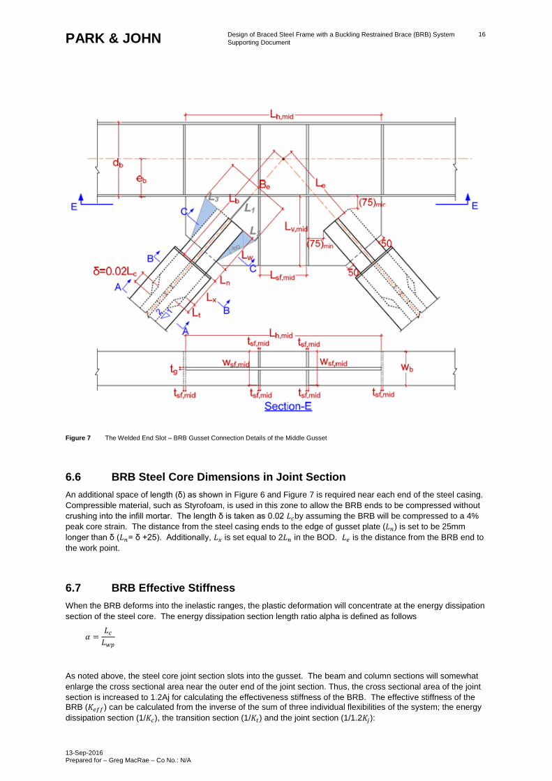
Figure 7 The Welded End Slot – BRB Gusset Connection Details of the Middle Gusset
6.6 BRB Steel Core Dimensions in Joint Section
An additional space of length (δ) as shown in Figure 6 and Figure 7 is required near each end of the steel casing.
Compressible material, such as Styrofoam, is used in this zone to allow the BRB ends to be compressed without
crushing into the infill mortar. The length δ is taken as 0.02 𝐿𝑐by assuming the BRB will be compressed to a 4%
peak core strain. The distance from the steel casing ends to the edge of gusset plate (𝐿𝑛) is set to be 25mm
longer than δ (𝐿𝑛= δ +25). Additionally, 𝐿𝑥 is set equal to 2𝐿𝑛 in the BOD. 𝐿𝑒 is the distance from the BRB end to
the work point.
6.7 BRB Effective Stiffness
When the BRB deforms into the inelastic ranges, the plastic deformation will concentrate at the energy dissipation
section of the steel core. The energy dissipation section length ratio alpha is defined as follows
𝛼 =𝐿𝑐
𝐿𝑤𝑝
As noted above, the steel core joint section slots into the gusset. The beam and column sections will somewhat
enlarge the cross sectional area near the outer end of the joint section. Thus, the cross sectional area of the joint
section is increased to 1.2Aj for calculating the effectiveness stiffness of the BRB. The effective stiffness of the
BRB (𝐾𝑒𝑓𝑓) can be calculated from the inverse of the sum of three individual flexibilities of the system; the energy
dissipation section (1/𝐾𝑐), the transition section (1/𝐾𝑡) and the joint section (1/1.2𝐾𝑗):
Design of Braced Steel Frame with a Buckling Restrained Brace (BRB) System
Supporting Document
13-Sep-2016 Prepared for – Greg MacRae – Co No.: N/A
17 PARK & JOHN
𝐾𝑒𝑓𝑓 =1
1
𝐾𝑐+
1
𝐾𝑡+
1
1.2𝐾𝑗
=𝐸𝐴𝑐𝐴𝑡𝐴𝑗
𝐿𝑐𝐴𝑡𝐴𝑗+2𝐿𝑐𝐴𝑐𝐴𝑗+𝐿𝑗,𝑤𝑝𝐴𝑐𝐴𝑡
1.2
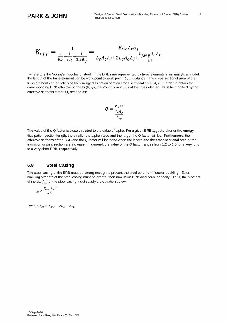
, where E is the Young’s modulus of steel. If the BRBs are represented by truss elements in an analytical model, the length of the truss element can be work point to work point (𝐿𝑤𝑝) distance. The cross sectional area of the
truss element can be taken as the energy dissipation section cross sectional area (𝐴𝑐). In order to obtain the
corresponding BRB effective stiffness (𝐾𝑒𝑓𝑓), the Young’s modulus of the truss element must be modified by the
effective stiffness factor, Q, defined as:
𝑄 =𝐾𝑒𝑓𝑓
𝐸𝐴𝑐
𝐿𝑤𝑝
The value of the Q factor is closely related to the value of alpha. For a given BRB 𝐿𝑤𝑝, the shorter the energy
dissipation section length, the smaller the alpha value and the larger the Q factor will be. Furthermore, the
effective stiffness of the BRB and the Q factor will increase when the length and the cross sectional area of the
transition or joint section are increase. In general, the value of the Q factor ranges from 1.2 to 1.5 for a very long
to a very short BRB, respectively.
6.8 Steel Casing
The steel casing of the BRB must be strong enough to prevent the steel core from flexural buckling. Euler
buckling strength of the steel casing must be greater than maximum BRB axial force capacity. Thus, the moment
of inertia (𝐼𝑠𝑐) of the steel casing must satisfy the equation below:
𝐼𝑠𝑐 ≥𝑃𝑚𝑎𝑥𝐿𝑠𝑐
2
𝜋2𝐸
, where 𝐿𝑠𝑐 = 𝐿𝑏𝑟𝑏 − 2𝐿𝑤 − 2𝐿𝑛
Design of Braced Steel Frame with a Buckling Restrained Brace (BRB) System
Supporting Document
13-Sep-2016 Prepared for – Greg MacRae – Co No.: N/A
18 PARK & JOHN
7.0 Gusset Plate Design
7.1 Corner Gusset Plate
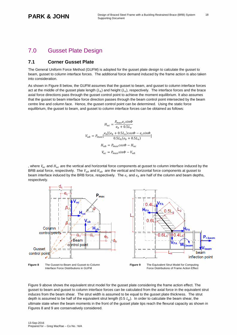
The General Uniform Force Method (GUFM) is adopted for the gusset plate design to calculate the gusset to
beam, gusset to column interface forces. The additional force demand induced by the frame action is also taken
into consideration.
As shown in Figure 8 below, the GUFM assumes that the gusset to beam, and gusset to column interface forces
act at the middle of the gusset plate length (𝐿ℎ) and height (𝐿𝑣), respectively. The interface forces and the brace
axial force directions pass through the gusset control point to achieve the moment equilibrium. It also assumes
that the gusset to beam interface force direction passes through the beam control point intersected by the beam
centre line and column face. Hence, the gusset control point can be determined. Using the static force
equilibrium, the gusset to beam, and gusset to column interface forces can be obtained as follows:
𝐻𝑢𝑐 =𝑃𝑚𝑎𝑥𝑒𝑐𝑠𝑖𝑛𝛷
𝑒𝑏 + 0.5𝐿𝑣
𝑉𝑢𝑏 = 𝑃𝑚𝑎𝑥[𝑒𝑏[(𝑒𝑏 + 0.5𝐿𝑣)𝑐𝑜𝑠𝛷 − 𝑒𝑐𝑠𝑖𝑛𝛷
0.5𝐿ℎ(𝑒𝑏 + 0.5𝐿𝑣)]
𝐻𝑢𝑏 = 𝑃𝑚𝑎𝑥𝑐𝑜𝑠𝛷 − 𝐻𝑢𝑐
𝑉𝑢𝑐 = 𝑃𝑚𝑎𝑥𝑠𝑖𝑛𝛷 − 𝑉𝑢𝑏
, where 𝑉𝑢𝑐 and 𝐻𝑢𝑐 are the vertical and horizontal force components at gusset to column interface induced by the
BRB axial force, respectively. The 𝑉𝑢𝑏 and 𝐻𝑢𝑏 are the vertical and horizontal force components at gusset to
beam interface induced by the BRB force, respectively. The 𝑒𝑐 and 𝑒𝑏 are half of the column and beam depths,
respectively.
Figure 8 The Gusset-to-Beam and Gusset-to-Column Figure 9 The Equivalent Strut Model for Computing
Interface Force Distributions in GUFM Force Distributions of Frame Action Effect
Figure 9 above shows the equivalent strut model for the gusset plate considering the frame action effect. The
gusset to beam and gusset to column interface forces can be calculated from the axial force in the equivalent strut
induces from the beam shear. The strut width is assumed to be equal to the gusset plate thickness. The strut
depth is assumed to be half of the equivalent strut length (0.5 𝐿𝑔). In order to calculate the beam shear, the
ultimate state when the beam moments in the front of the gusset plate tips reach the flexural capacity as shown in
Figures 8 and 9 are conservatively considered.
Design of Braced Steel Frame with a Buckling Restrained Brace (BRB) System
Supporting Document
13-Sep-2016 Prepared for – Greg MacRae – Co No.: N/A
19 PARK & JOHN
Since the beams are required to sustain the substantial axial force (𝑃𝑟,𝑏𝑒𝑎𝑚) induced by the BRB axial
deformations, the beam reduced flexural capacity (𝑀𝑟,𝑏𝑒𝑎𝑚) is calculated according to the axial force and flexural
interaction, but without strength reduction factor as follows:
𝑖𝑓 𝑃𝑟,𝑏𝑒𝑎𝑚
𝑃𝑛,𝑏𝑒𝑎𝑚 ≥ 0.2,
𝑃𝑟,𝑏𝑒𝑎𝑚
𝑃𝑛,𝑏𝑒𝑎𝑚 +
8
9(
𝑀𝑟,𝑏𝑒𝑎𝑚
𝑀𝑛,𝑏𝑒𝑎𝑚 ) = 1.0
𝑖𝑓 𝑃𝑟,𝑏𝑒𝑎𝑚
𝑃𝑛,𝑏𝑒𝑎𝑚 < 0.2,
𝑃𝑟,𝑏𝑒𝑎𝑚
2𝑃𝑛,𝑏𝑒𝑎𝑚 + (
𝑀𝑟,𝑏𝑒𝑎𝑚
𝑀𝑛,𝑏𝑒𝑎𝑚 ) = 1.0
Where𝑀𝑛,𝑏𝑒𝑎𝑚 is the plastic moment capacity of the beam and 𝑃𝑛,𝑏𝑒𝑎𝑚 is the compression capacity of the beam
assuming the beam is fully laterally supported. The axial force demand on the beam (𝑃𝑟,𝑏𝑒𝑎𝑚) can be represented
by the horizontal force component of the maximum BRB axial force (𝑃𝑚𝑎𝑥) as:
𝑃𝑟,𝑏𝑒𝑎𝑚 = 𝑃𝑚𝑎𝑥𝑐𝑜𝑠𝛷
Hence, the corresponding beam shear demand (𝑉𝑏𝑒𝑎𝑚), no greater than the plastic shear capacity of the beam,
can be calculated considering the clear span of the beam (𝐿𝑐𝑙𝑒𝑎𝑟) and the material over strength (𝑅𝑦,𝑏𝑒𝑎𝑚) factor:
𝑉𝑏𝑒𝑎𝑚 =2(𝑅𝑦,𝑏𝑒𝑎𝑚𝑀𝑟,𝑏𝑒𝑎𝑚)
𝐿𝑐𝑙𝑒𝑎𝑟≤ 𝑉𝑝,𝑏𝑒𝑎𝑚 = 0.6𝑅𝑦,𝑏𝑒𝑎𝑚𝐹𝑦,𝑏𝑒𝑎𝑚𝑡𝑤(𝑑𝑏 − 2𝑡𝑓)
Where, 𝐹𝑦,𝑏𝑒𝑎𝑚 is the yield stress of the beam material, Tw and Tf are the thicknesses of the beam web and
flange, respectively. For the single diagonal BRB configuration, the beam clear span, 𝐿𝑐𝑙𝑒𝑎𝑟 is:
𝐿𝑐𝑙𝑒𝑎𝑟 = 𝐿𝑏𝑒𝑎𝑚 − 0.5𝑑𝑐,𝑙𝑒𝑓𝑡 − 0.5𝑑𝑐,𝑟𝑖𝑔ℎ𝑡 − 𝐿ℎ,𝑢𝑝𝑝𝑒𝑟 − 𝐿ℎ,𝑙𝑜𝑤𝑒𝑟
, assuming that the frame and brace dimensions in the stories above and below the design target storey are
identical with the dimensions in the design target storey.
Considering the compatibility condition, the horizontal deformation components of the equivalent strut (𝐷𝑠𝑡𝑟𝑢𝑡,𝑥)
induced by the beam shear and the horizontal deformation component of beam top surface at the location of 0.60
𝐿ℎ (𝐷𝑏𝑒𝑎𝑚,𝑥) must be equal. Hence, the equivalent strut horizontal (𝐻𝐹𝐴), and vertical (𝑉𝐹𝐴) force components can
be calculated as below:
𝐻𝐹𝐴 =𝑑𝑏𝐿ℎ𝑉𝑏𝑒𝑎𝑚[0.3(𝐿𝑏𝑒𝑎𝑚 − 0.5𝑑𝑐,𝑙𝑒𝑓𝑡 − 0.5𝑑𝑐,𝑟𝑖𝑔ℎ𝑡) − 0.18𝐿ℎ
4𝐼𝑏
𝑡𝑔+ 𝑑𝑏𝐿ℎ(0.3𝑑𝑏 + 0.18𝐿𝑣
𝑉𝐹𝐴 =𝑑𝑏𝐿𝑣𝑉𝑏𝑒𝑎𝑚[0.3(𝐿𝑏𝑒𝑎𝑚 − 0.5𝑑𝑐,𝑙𝑒𝑓𝑡 − 0.5𝑑𝑐,𝑟𝑖𝑔ℎ𝑡) − 0.18𝐿ℎ
4𝐼𝑏
𝑡𝑔+ 𝑑𝑏𝐿ℎ(0.3𝑑𝑏 + 0.18𝐿𝑣)
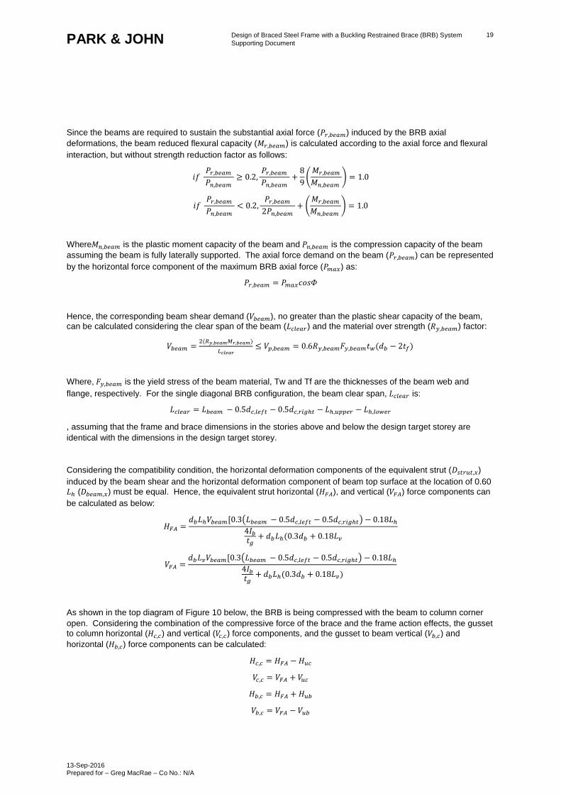
As shown in the top diagram of Figure 10 below, the BRB is being compressed with the beam to column corner
open. Considering the combination of the compressive force of the brace and the frame action effects, the gusset
to column horizontal (𝐻𝑐,𝑐) and vertical (𝑉𝑐,𝑐) force components, and the gusset to beam vertical (𝑉𝑏,𝑐) and
horizontal (𝐻𝑏,𝑐) force components can be calculated:
𝐻𝑐,𝑐 = 𝐻𝐹𝐴 − 𝐻𝑢𝑐
𝑉𝑐,𝑐 = 𝑉𝐹𝐴 + 𝑉𝑢𝑐
𝐻𝑏,𝑐 = 𝐻𝐹𝐴 + 𝐻𝑢𝑏
𝑉𝑏,𝑐 = 𝑉𝐹𝐴 − 𝑉𝑢𝑏
Design of Braced Steel Frame with a Buckling Restrained Brace (BRB) System
Supporting Document
13-Sep-2016 Prepared for – Greg MacRae – Co No.: N/A
20 PARK & JOHN
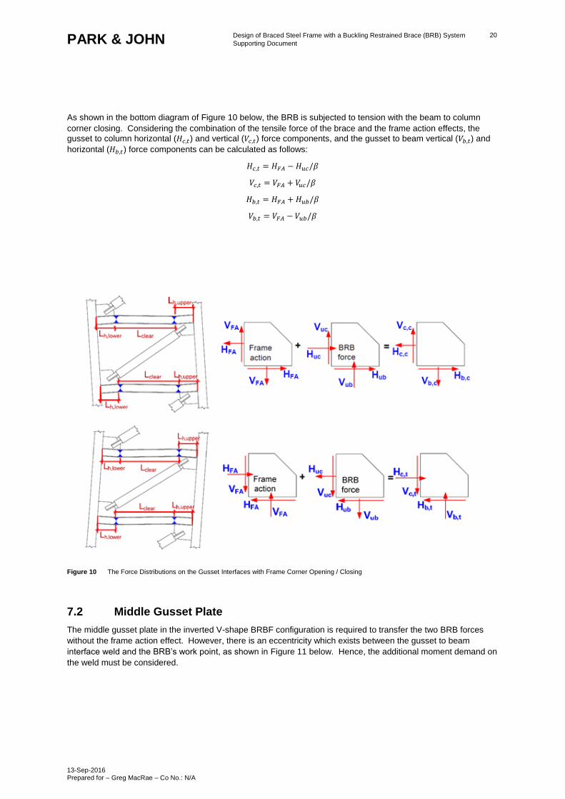
As shown in the bottom diagram of Figure 10 below, the BRB is subjected to tension with the beam to column
corner closing. Considering the combination of the tensile force of the brace and the frame action effects, the
gusset to column horizontal (𝐻𝑐,𝑡) and vertical (𝑉𝑐,𝑡) force components, and the gusset to beam vertical (𝑉𝑏,𝑡) and
horizontal (𝐻𝑏,𝑡) force components can be calculated as follows:
𝐻𝑐,𝑡 = 𝐻𝐹𝐴 − 𝐻𝑢𝑐/𝛽
𝑉𝑐,𝑡 = 𝑉𝐹𝐴 + 𝑉𝑢𝑐/𝛽
𝐻𝑏,𝑡 = 𝐻𝐹𝐴 + 𝐻𝑢𝑏/𝛽
𝑉𝑏,𝑡 = 𝑉𝐹𝐴 − 𝑉𝑢𝑏/𝛽
Figure 10 The Force Distributions on the Gusset Interfaces with Frame Corner Opening / Closing
7.2 Middle Gusset Plate
The middle gusset plate in the inverted V-shape BRBF configuration is required to transfer the two BRB forces
without the frame action effect. However, there is an eccentricity which exists between the gusset to beam
interface weld and the BRB’s work point, as shown in Figure 11 below. Hence, the additional moment demand on
the weld must be considered.
Design of Braced Steel Frame with a Buckling Restrained Brace (BRB) System
Supporting Document
13-Sep-2016 Prepared for – Greg MacRae – Co No.: N/A
21 PARK & JOHN
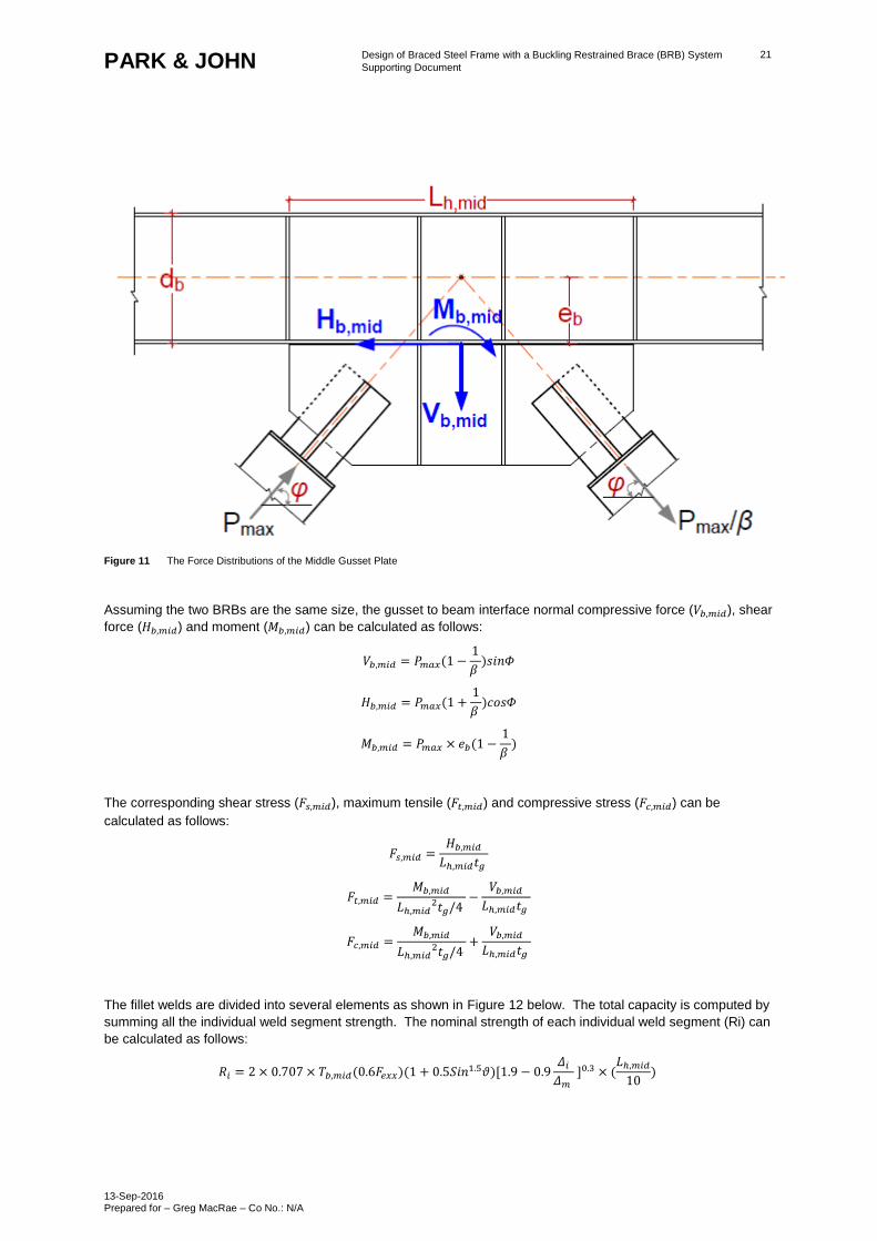
Figure 11 The Force Distributions of the Middle Gusset Plate
Assuming the two BRBs are the same size, the gusset to beam interface normal compressive force (𝑉𝑏,𝑚𝑖𝑑), shear
force (𝐻𝑏,𝑚𝑖𝑑) and moment (𝑀𝑏,𝑚𝑖𝑑) can be calculated as follows:
𝑉𝑏,𝑚𝑖𝑑 = 𝑃𝑚𝑎𝑥(1 −1
𝛽 )𝑠𝑖𝑛𝛷
𝐻𝑏,𝑚𝑖𝑑 = 𝑃𝑚𝑎𝑥(1 +1
𝛽 )𝑐𝑜𝑠𝛷
𝑀𝑏,𝑚𝑖𝑑 = 𝑃𝑚𝑎𝑥 × 𝑒𝑏(1 −1
𝛽 )
The corresponding shear stress (𝐹𝑠,𝑚𝑖𝑑), maximum tensile (𝐹𝑡,𝑚𝑖𝑑) and compressive stress (𝐹𝑐,𝑚𝑖𝑑) can be
calculated as follows:
𝐹𝑠,𝑚𝑖𝑑 =𝐻𝑏,𝑚𝑖𝑑
𝐿ℎ,𝑚𝑖𝑑𝑡𝑔
𝐹𝑡,𝑚𝑖𝑑 =𝑀𝑏,𝑚𝑖𝑑
𝐿ℎ,𝑚𝑖𝑑2𝑡𝑔/4
−𝑉𝑏,𝑚𝑖𝑑
𝐿ℎ,𝑚𝑖𝑑𝑡𝑔
𝐹𝑐,𝑚𝑖𝑑 =𝑀𝑏,𝑚𝑖𝑑
𝐿ℎ,𝑚𝑖𝑑2𝑡𝑔/4
+𝑉𝑏,𝑚𝑖𝑑
𝐿ℎ,𝑚𝑖𝑑𝑡𝑔
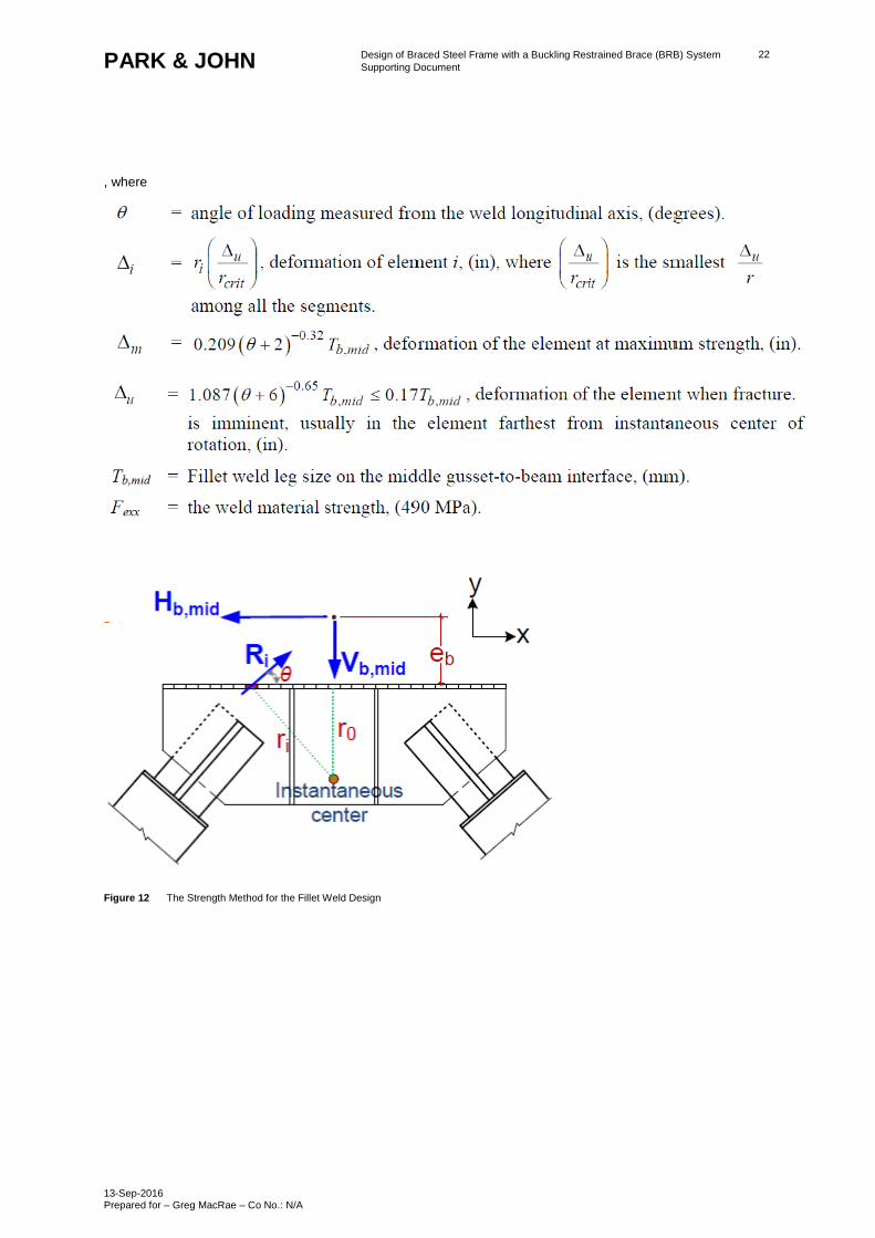
The fillet welds are divided into several elements as shown in Figure 12 below. The total capacity is computed by
summing all the individual weld segment strength. The nominal strength of each individual weld segment (Ri) can
be calculated as follows:
𝑅𝑖 = 2 × 0.707 × 𝑇𝑏,𝑚𝑖𝑑(0.6𝐹𝑒𝑥𝑥)(1 + 0.5𝑆𝑖𝑛1.5𝜗)[1.9 − 0.9𝛥𝑖
𝛥𝑚 ]0.3 × (
𝐿ℎ,𝑚𝑖𝑑
10)
Design of Braced Steel Frame with a Buckling Restrained Brace (BRB) System
Supporting Document
13-Sep-2016 Prepared for – Greg MacRae – Co No.: N/A
22 PARK & JOHN
, where
Figure 12 The Strength Method for the Fillet Weld Design
Design of Braced Steel Frame with a Buckling Restrained Brace (BRB) System
Supporting Document
13-Sep-2016 Prepared for – Greg MacRae – Co No.: N/A
23 PARK & JOHN
8.0 Demand to Capacity Ratio (DCR) Checks
Following the capacity design principles the following demand to capacity ratio checks were performed:
- Steel Casing Buckling
- Joint Region Yielding
- Joint Region Buckling
- Gusset Plate Block Shear Failure
- Gusset Plate Yielding
- Gusset Plate Buckling
- Gusset Strength at the Connections to the Beam and Column
8.1 Steel casing buckling (DCR 1)
The minimum second moment of inertia (𝐼𝑠𝑐,𝑚𝑖𝑛) to prevent steel casing buckling can be computed from
𝐼𝑠𝑐,𝑚𝑖𝑛 ≥𝑃𝑚𝑎𝑥𝐿𝑠𝑐
2
𝜋2𝐸
Where,
𝐿𝑠𝑐 = 𝐿𝑏𝑟𝑏 − 2𝐿𝑤 − 2𝐿𝑛
𝐿𝑠𝑐 = 7182 − 2 × 300 − 2 × 150
𝐿𝑠𝑐 = 7014
𝐼𝑠𝑐,𝑚𝑖𝑛 ≥4830 × 70142
𝜋2 × 20000
𝐼𝑠𝑐,𝑚𝑖𝑛 ≥ 120500 𝑚𝑚4
Choose grade 300 CHS 406.4x3.4
𝐼𝑠𝑐 = 161 × 106𝑚𝑚4 > 𝐼𝑠𝑐,𝑚𝑖𝑛 ∴ 𝑠𝑎𝑓𝑒
8.2 Joint region yielding (DCR-2)
For joint region yielding, check
𝛷𝐴𝑗𝐹𝑦𝑅𝑦 ≫ 𝑃𝑚𝑎𝑥
𝛽
𝛷𝐴𝑗𝐹𝑦𝑅𝑦 = 0.9 × 90000 × 300 × 1.25
𝛷𝐴𝑗𝐹𝑦𝑅𝑦 = 30375𝑘𝑁
𝑃𝑚𝑎𝑥
𝛽=
4830
1.15= 4200kN
𝛷𝐴𝑗𝐹𝑦𝑅𝑦 > 𝑃𝑚𝑎𝑥
𝛽 ∴ 𝑠𝑎𝑓𝑒
Design of Braced Steel Frame with a Buckling Restrained Brace (BRB) System
Supporting Document
13-Sep-2016 Prepared for – Greg MacRae – Co No.: N/A
24 PARK & JOHN
8.3 Joint region buckling (DCR-3)
For joint region buckling, check
𝛷 × min {𝜋2𝐸𝐼𝑦𝑗
4(𝐿𝑏,𝑢𝑝𝑝𝑒𝑟+𝛿2, 𝐴𝑗𝐹𝑦𝑅𝑦} > 𝑃𝑚𝑎𝑥
𝛷 × min {𝜋2𝐸𝐼𝑦𝑗
4(𝐿𝑏,𝑙𝑜𝑤𝑒𝑟+𝛿2, 𝐴𝑗𝐹𝑦𝑅𝑦} > 𝑃𝑚𝑎𝑥
Where 𝐼𝑦𝑗 is the second moment of inertia of the joint region.
𝛷𝐴𝑗𝐹𝑦𝑅𝑦 = 0.9 × 90000 × 300 × 1.25
𝛷𝐴𝑗𝐹𝑦𝑅𝑦 = 30375𝑘𝑁
𝑃𝑚𝑎𝑥 = 4830𝑘𝑁
𝛷𝐴𝑗𝐹𝑦𝑅𝑦 > 𝑃𝑚𝑎𝑥 ∴ 𝑠𝑎𝑓𝑒
8.4 Gusset plate block shear failure (DCR-4)
For Gusset plate block shear failure check
𝛷𝑃𝑛 ≥ 𝑃𝑚𝑎𝑥
Where, 𝑃𝑛 = 0.6𝐹𝑢,𝑔𝐴𝑛𝑣 + 𝐹𝑢,𝑔 𝐴𝑛𝑡 ≤ 0.6𝐹𝑦,𝑔𝐴𝑛𝑣 + 𝐹𝑢,𝑔 𝐴𝑛𝑡
𝛷 = 0.75
𝐹𝑢,𝑔 = 250𝑁/𝑚𝑚2
𝐹𝑦,𝑔 = 280𝑁/𝑚𝑚2
𝐴𝑔𝑣 = 𝐴𝑛𝑣 = 2𝐿𝑤 × 𝑡𝑔
𝐴𝑔𝑣 = 𝐴𝑛𝑣 = 23083.36 𝑚𝑚2
𝐴𝑔𝑡 = 𝐴𝑛𝑡 = 𝐷𝑗 × 𝑡𝑔
𝐴𝑔𝑡 = 𝐴𝑛𝑡 = 12000 𝑚𝑚2
𝑃𝑛 = 0.6 × 250 × 23083.36 + 280 × 12000 ≤ 0.6 × 280 × 23083.36 + 280 × 12000
𝑃𝑛 = 6462.49𝑘𝑁
𝛷𝑃𝑛 = 4846.87𝑘𝑁
𝑃𝑚𝑎𝑥 = 4830𝑘𝑁
𝛷𝑃𝑛 ≥ 𝑃𝑚𝑎𝑥 ∴ 𝑠𝑎𝑓𝑒
Design of Braced Steel Frame with a Buckling Restrained Brace (BRB) System
Supporting Document
13-Sep-2016 Prepared for – Greg MacRae – Co No.: N/A
25 PARK & JOHN
8.5 Gusset plate yielding (DCR-5)
The capacity of the gusset plate responsible for transferring the BRB tension can be computed by calculating the
yield capacity of the whitmore section on the gusset plate. The whitmore section region is determined by
extending the BRB end-to gusset weld pattern at a 30-egree angle .The whitmore section width can be computed
as follows
𝑊𝑤ℎ𝑖𝑡𝑚𝑜𝑟𝑒 = 2𝐿𝑤 × tan(30) + 𝐷𝑗
𝑊𝑤ℎ𝑖𝑡𝑚𝑜𝑟𝑒 = 2 × 300 × tan(30) + 300
𝑊𝑤ℎ𝑖𝑡𝑚𝑜𝑟𝑒 = 646.41𝑚𝑚
The gusset plate yielding can be calculated using the section effective width, 𝐵𝑒,the smaller dimension of
𝑊𝑤ℎ𝑖𝑡𝑚𝑜𝑟𝑒 and𝑊𝑎𝑐𝑡𝑢𝑎𝑙.
For gusset plate yielding check
𝛷𝐹𝑦,𝑔𝐵𝑒𝑡𝑔 ≥𝑃𝑚𝑎𝑥
𝛽
𝛷 = 0.9
𝛷𝐹𝑦,𝑔𝐵𝑒𝑡𝑔 = 0.9 × 250 × 646.31 × 40
𝛷𝐹𝑦,𝑔𝐵𝑒𝑡𝑔 = 6503.38 𝑘𝑁
𝑃𝑚𝑎𝑥
𝛽=
4830
1.15= 4200kN
𝛷𝐹𝑦,𝑔𝐵𝑒𝑡𝑔 ≥𝑃𝑚𝑎𝑥
𝛽∴ 𝑠𝑎𝑓𝑒
8.6 Gusset plate buckling (DCR-6)
The gusset plate compressive strength can be computed by adopting the effective width, 𝐵𝑒 and the average of
the three critical lengths as the buckling length (𝐿𝑟). The critical lengths 𝐿1, 𝐿2and𝐿3 can be determined as shown
from the above figures.
𝐿𝑟 =𝐿1 + 𝐿2 + 𝐿3
3
𝐿𝑟 =300 + 200 + 25
3
𝐿𝑟 = 175
The gusset plate compressive strength can be determined from the following equation
𝛷𝑃𝑐𝑟,𝑔 = 𝛷 × (𝐵𝑒 × 𝑡𝑔) × 𝐹𝑐𝑟,𝑔 ≥ 𝑃𝑚𝑎𝑥
𝜆𝑐 =𝐾 × 𝐿𝑟
𝜋𝑟√
𝐹𝑦,𝑔
𝐸
𝐾 = 0.65
𝜆𝑐 =0.65 × 175
𝜋 × 1.82√
250
2 × 10⁵
𝜆𝑐 = 0.74 < 1.5
Design of Braced Steel Frame with a Buckling Restrained Brace (BRB) System
Supporting Document
13-Sep-2016 Prepared for – Greg MacRae – Co No.: N/A
26 PARK & JOHN
𝐹𝑐𝑟,𝑔 = 0.658𝜆𝑐2
𝐹𝑦,𝑔
𝐹𝑐𝑟,𝑔 = 0.6580.742× 250
𝐹𝑐𝑟,𝑔 = 222.31
𝛷𝑃𝑐𝑟,𝑔 = 0.9 × (646.31 × 40) × 222.31
𝛷𝑃𝑐𝑟,𝑔 = 5153.55𝑘𝑁 ≥ 𝑃𝑚𝑎𝑥 ∴ 𝑠𝑎𝑓𝑒
8.7 Gusset plate strength at the connections to the beam and column
(DCR-7)
8.7.1 Von Mises yield criterion (DCR7-1 and DCR 7-4)
The maximum von Mises stress computed from the normal and shear stress under the maximum brace axial force
and frame action effect must be no greater than the yield stress of the gusset plate material. The following
requirements are considered.
Criteria 1
√(𝐻𝑐𝑐
𝐿𝑣𝑡𝑔 + 𝑤𝑠𝑓,𝑒𝑓𝑓𝑡𝑠𝑓)2 + 3(
𝑉𝑐𝑐
𝐿𝑣𝑡𝑔 + 𝑤𝑠𝑓,𝑒𝑓𝑓𝑡𝑠𝑓)2 ≤ 𝛷𝐹𝑦,𝑔
Effective width of the gusset edge stiffener,𝑤𝑠𝑓,𝑒𝑓𝑓 = 2.5𝑡𝑔 = 100
Thickness of the stiffener,𝑡𝑠𝑓=40mm
√(3627.05
700 × 40 + 100 × 25)2 + 3(
1268.86
700 × 40 + 100 × 25)2 ≤ 250
0.1325 ≤ 250 ∴ 𝑠𝑎𝑓𝑒
Criteria 2
√(𝑉𝑏,𝑐
𝐿ℎ𝑡𝑔 + 𝑤𝑠𝑓,𝑒𝑓𝑓𝑡𝑠𝑓)2 + 3(
𝐻𝑏,𝑐
𝐿ℎ𝑡𝑔 + 𝑤𝑠𝑓,𝑒𝑓𝑓𝑡𝑠𝑓)2 ≤ 𝛷𝐹𝑦,𝑔
√(1219.6
800 × 40 + 100 × 25)2 + 3(
8456.75
800 × 40 + 100 × 25)2 ≤ 250
0.4082 ≤ 250 ∴ 𝑠𝑎𝑓𝑒
Design of Braced Steel Frame with a Buckling Restrained Brace (BRB) System
Supporting Document
13-Sep-2016 Prepared for – Greg MacRae – Co No.: N/A
27 PARK & JOHN
Partial cross-sectional area of the gusset edge stiffener could be taken into account for the gusset to beam and
gusset to column interface area.
The von Mises yield criterion for the middle gusset to beam interface should satisfy the following requirement
√(𝑉𝑏,𝑚𝑖𝑑
𝐿ℎ,𝑚𝑖𝑑𝑡𝑔+
𝑀𝑏,𝑚𝑖𝑑
𝐿ℎ𝑚𝑖𝑑2𝑡𝑔
4⁄
)2 + 3(𝐻𝑏,𝑚𝑖𝑑
𝐿ℎ,𝑚𝑖𝑑𝑡𝑔)2 ≤ 𝛷𝐹𝑦,𝑔
√(6.42
1600 × 40+
103
16002 × 404⁄
)2 + 3(9029.53
1600 × 40)2 ≤ 250
0.244 ≤ 250 ∴ 𝑠𝑎𝑓𝑒
8.7.2 Tensile rupture criteria (DCR 7-2 AND 7-5)
The tensile rupture strength at gusset to beam and gusset to column interface must satisfy the following
requirements
Criteria 1
𝐻𝑐𝑐
𝐿𝑣𝑡𝑔 + 𝑤𝑠𝑓,𝑒𝑓𝑓𝑡𝑠𝑓≤ 𝛷𝐹𝑦,𝑔
3627.09
700 × 40 + 100 × 25≤ 250
0.113 ≤ 250 ∴ 𝑠𝑎𝑓𝑒
Criteria 2
𝐻𝑐𝑡
𝐿𝑣𝑡𝑔 + 𝑤𝑠𝑓,𝑒𝑓𝑓𝑡𝑠𝑓≤ 𝛷𝐹𝑦,𝑔
3629.05
700 × 40 + 100 × 25≤ 250
0.113 ≤ 250 ∴ 𝑠𝑎𝑓𝑒
Criteria 3
𝑉𝑏,𝑐
𝐿ℎ𝑡𝑔 + 𝑤𝑠𝑓,𝑒𝑓𝑓𝑡𝑠𝑓≤ 𝛷𝐹𝑦,𝑔
1219.6
800 × 40 + 100 × 25≤ 250
0.033 ≤ 250 ∴ 𝑠𝑎𝑓𝑒
Criteria 4
Design of Braced Steel Frame with a Buckling Restrained Brace (BRB) System
Supporting Document
13-Sep-2016 Prepared for – Greg MacRae – Co No.: N/A
28 PARK & JOHN
𝑉𝑏,𝑡
𝐿ℎ𝑡𝑔 + 𝑤𝑠𝑓,𝑒𝑓𝑓𝑡𝑠𝑓≤ 𝛷𝐹𝑦,𝑔
1476.27
800 × 40 + 100 × 25≤ 250
0.041 ≤ 250 ∴ 𝑠𝑎𝑓𝑒
8.7.3 Shear rupture criteria (DCR-7-3AND DCR 7-6)
Criteria 1
𝑉𝑐𝑐
𝐿𝑣𝑡𝑔 + 𝑤𝑠𝑓,𝑒𝑓𝑓𝑡𝑠𝑓≤ 𝛷𝜏𝑢,𝑔 = 𝛷(0.6𝐹𝑦,𝑔)
1268.86
700 × 40 + 100 × 25≤ 150
0.0396 ≤ 150 ∴ 𝑠𝑎𝑓𝑒
Criteria 2
𝐻𝑏,𝑐
𝐿ℎ𝑡𝑔 + 𝑤𝑠𝑓,𝑒𝑓𝑓𝑡𝑠𝑓≤ 𝛷𝜏𝑢,𝑔 = 𝛷(0.6𝐹𝑦,𝑔)
8456.75
800 × 40 + 100 × 25≤ 150
0.264 ≤ 150 ∴ 𝑠𝑎𝑓𝑒
For middle gusset plate
𝐹𝑠,𝑚𝑖𝑑 =𝐻𝑏,𝑚𝑖𝑑
𝐿ℎ,𝑚𝑖𝑑𝑡𝑔≤ 𝛷𝜏𝑢,𝑔
𝐹𝑠,𝑚𝑖𝑑 =9029.53
1600 × 40≤ 150
𝐹𝑠,𝑚𝑖𝑑 = 0.141 ≤ 150 ∴ 𝑠𝑎𝑓𝑒
Design of Braced Steel Frame with a Buckling Restrained Brace (BRB) System
Supporting Document
13-Sep-2016 Prepared for – Greg MacRae – Co No.: N/A
29 PARK & JOHN
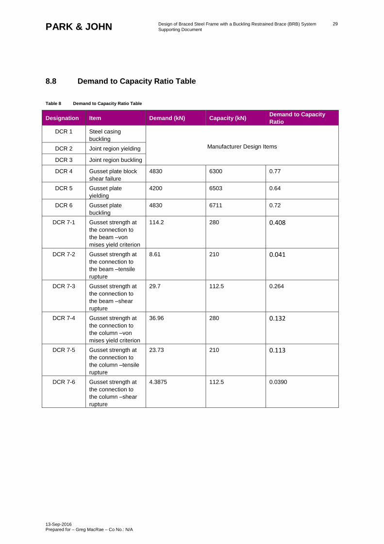
8.8 Demand to Capacity Ratio Table
Table 8 Demand to Capacity Ratio Table
Designation Item Demand (kN) Capacity (kN) Demand to Capacity
Ratio
DCR 1 Steel casing
buckling
Manufacturer Design Items DCR 2 Joint region yielding
DCR 3 Joint region buckling
DCR 4 Gusset plate block
shear failure
4830 6300 0.77
DCR 5 Gusset plate
yielding
4200 6503 0.64
DCR 6 Gusset plate
buckling
4830 6711 0.72
DCR 7-1 Gusset strength at
the connection to
the beam –von
mises yield criterion
114.2 280 0.408
DCR 7-2 Gusset strength at
the connection to
the beam –tensile
rupture
8.61 210 0.041
DCR 7-3 Gusset strength at
the connection to
the beam –shear
rupture
29.7 112.5 0.264
DCR 7-4 Gusset strength at
the connection to
the column –von
mises yield criterion
36.96 280 0.132
DCR 7-5 Gusset strength at
the connection to
the column –tensile
rupture
23.73 210 0.113
DCR 7-6 Gusset strength at
the connection to
the column –shear
rupture
4.3875 112.5 0.0390
Design of Braced Steel Frame with a Buckling Restrained Brace (BRB) System
Supporting Document
13-Sep-2016 Prepared for – Greg MacRae – Co No.: N/A
30 PARK & JOHN
9.0 Diaphragm design
In accordance with the manufacturer’s design documents / specification, 170mm thick concrete slab with 0.95mm
Hibond flooring system was selected.
The diaphragm demands were obtained through the pESA method.
The BRB overstrength governed at a factor of 1.34, and the dynamic amplification factor of 1.5 were used. The
derivation of the demands is shown in Table 9 below. The demands were then distributed evenly around the floor
for analysis, as shown in Figure 13 below.
Table 9 pESA Diaphragm Demands
Storey Force (kN) PGA (kN) 2 x ESA (kN) pESA (kN)
500 116 1000 1161
1000 2323 2000 2323
1500 3484 3000 3484
2106 3941 4211 4211
Figure 13 pESA Diaphragm Force Demand Distribution
Design of Braced Steel Frame with a Buckling Restrained Brace (BRB) System
Supporting Document
13-Sep-2016 Prepared for – Greg MacRae – Co No.: N/A
31 PARK & JOHN
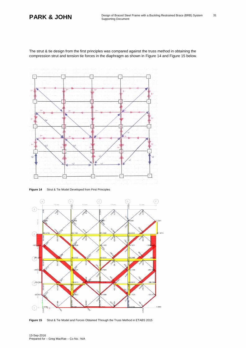
The strut & tie design from the first principles was compared against the truss method in obtaining the
compression strut and tension tie forces in the diaphragm as shown in Figure 14 and Figure 15 below.
Figure 14 Strut & Tie Model Developed from First Principles
Figure 15 Strut & Tie Model and Forces Obtained Through the Truss Method in ETABS 2015
Design of Braced Steel Frame with a Buckling Restrained Brace (BRB) System
Supporting Document
13-Sep-2016 Prepared for – Greg MacRae – Co No.: N/A
32 PARK & JOHN
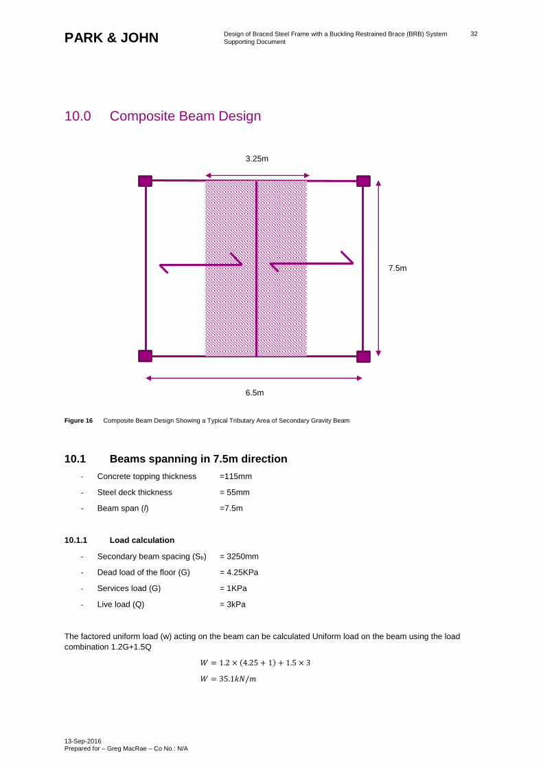
10.0 Composite Beam Design
Figure 16 Composite Beam Design Showing a Typical Tributary Area of Secondary Gravity Beam
10.1 Beams spanning in 7.5m direction
- Concrete topping thickness =115mm
- Steel deck thickness = 55mm
- Beam span (l) =7.5m
10.1.1 Load calculation
- Secondary beam spacing (Sb) = 3250mm
- Dead load of the floor (G) = 4.25KPa
- Services load (G) = 1KPa
- Live load (Q) = 3kPa
The factored uniform load (w) acting on the beam can be calculated Uniform load on the beam using the load
combination 1.2G+1.5Q
𝑊 = 1.2 × (4.25 + 1) + 1.5 × 3
𝑊 = 35.1𝑘𝑁/𝑚
7.5m
3.25m
6.5m
Design of Braced Steel Frame with a Buckling Restrained Brace (BRB) System
Supporting Document
13-Sep-2016 Prepared for – Greg MacRae – Co No.: N/A
33 PARK & JOHN
The moment demand M* on the beam can be calculated from the following equation considering the beam to be
simply supported
𝑀∗ = 𝑊𝑙2
8
𝑀∗ = 35.1 × 7.52
8
𝑀∗ = 246.79𝑘𝑁𝑚
The shear demand, V* on the beam can be calculated using the following equation considering the beam to be
simply supported
𝑉∗ = 𝑊𝑙
2
𝑉∗ = 35.1 × 7.5
2
𝑉∗ = 131.625𝑘𝑁
Effective width Be of the beam is
𝐵𝑒 = 𝑚𝑖𝑛 (𝑆𝑝
4, 𝑆𝑏)
𝐵𝑒 = 𝑚𝑖𝑛 (7500
4, 3250)
𝐵𝑒 = 1875𝑚𝑚
Choose 410 UB 59.7 for the composite beam
10.1.2 Beam Properties
The following beam properties were considered in the design:
- Depth of web (dw) = 380.4mm
- Thickness of web (tw) = 7.8mm
- Breadth of flange (bw) = 178mm
- Area of cross section, As = 7640 mm2
- Second moment of Inertia (Is) = 216000000 mm4
- Yield strength of steel fy =300Mpa
- Cylinder Compressive strength of concrete fc =30Mpa
10.1.3 Fully composite shear connection
The maximum compressive force (Cmax) can be calculated as
𝐶𝑚𝑎𝑥 = 0.85 × 𝐵𝑒 × 𝑡𝑐 × 𝑓′𝑐
𝐶𝑚𝑎𝑥 = 0.85 × 1875 × 190 × 30
𝐶𝑚𝑎𝑥 = 9084𝑘𝑁
Design of Braced Steel Frame with a Buckling Restrained Brace (BRB) System
Supporting Document
13-Sep-2016 Prepared for – Greg MacRae – Co No.: N/A
34 PARK & JOHN
The tensile force (T) can be calculated as
𝑇 = 𝐴𝑠 × 𝑓𝑦
𝑇 = 7640 × 300
𝑇 = 2292𝑘𝑁
Critical force on the interface (Fmin) can be computed using the following equation
𝐹𝑚𝑖𝑛 = min (𝐶𝑚𝑎𝑥, 𝑇)
𝐹𝑚𝑖𝑛 = min (9084,2292)
𝐹𝑚𝑖𝑛 = 2292𝑘𝑁
Since the compression force is stronger the neutral axis is in the slab. Depth of compression block (ac) is
determined from the following equation:
𝑎𝑐 =𝐹𝑚𝑖𝑛
0.85 × 𝑓′𝑐 × 𝐵𝑒
𝑎𝑐 =2292 × 103
0.85 × 30 × 1875
𝑎𝑐 = 47.93𝑚𝑚
Since 𝑎𝑐 is less than 𝑡𝑐
𝑒′ =𝑑
2+ 𝑡𝑐 −
𝑎𝑐
2
𝑒′ =406
2+ 170 −
47.93
2
𝑒′ = 349.03𝑚𝑚
The design flexural capacity(𝑀𝑟𝑐) of the beam can be calculated as
𝑀𝑟𝑐 = 𝐹𝑚𝑖𝑛 × 𝑒′
𝑀𝑟𝑐 = 2292 × 349.03
𝑀𝑟𝑐 = 800𝑘𝑁𝑚
The nominal flexural capacity(𝛷𝑀𝑟𝑐) of the beam can be calculated as
𝛷𝑀𝑟𝑐 = 0.9 × 800
𝛷𝑀𝑟𝑐 = 720𝑘𝑁𝑚
Since the flexural demand (𝑀∗) is less than the nominal flexural capacity(𝛷𝑀𝑟𝑐) the composite beam is safe in
flexure
Design of Braced Steel Frame with a Buckling Restrained Brace (BRB) System
Supporting Document
13-Sep-2016 Prepared for – Greg MacRae – Co No.: N/A
35 PARK & JOHN
10.1.4 Shear stud design
Use 20mm diameter shear stud
𝛼𝑑𝑠 = 1
𝛷𝑠𝑐 = 1
Ultimate strength of shear stud, 𝐹𝑢=415 MPa
Area of shear stud 𝐴𝑠𝑐 = 314mm2
Stud tensile force,𝐹𝑡𝑒𝑛 can be calculated as
𝐹𝑡𝑒𝑛 = 0.8 × 𝐴𝑠𝑐 × 𝐹𝑢
𝐹𝑡𝑒𝑛 = 0.8 × 314 × 415
𝐹𝑡𝑒𝑛 = 104.248kN
Concrete crushing force,𝐹𝑐𝑟𝑢 can be calculated as
𝐹𝑐𝑟𝑢 = 𝛼𝑑𝑠 × 0.13 × √𝑓′𝑐 × 𝐹𝑢 × 𝐴𝑠𝑐
𝐹𝑐𝑟𝑢 = 1 × 0.13 × √30 × 415 × 314
𝐹𝑐𝑟𝑢 = 92.78𝑘𝑁
Stud resistance(𝑞𝑟) can be calculated as
𝑞𝑟 = min (𝐹𝑡𝑒𝑛, 𝐹𝑐𝑟𝑢)
𝑞𝑟 = min (104.28,92.78)
𝑞𝑟 = 92.78𝑘𝑁
Number of shear studs required for half span =𝐹𝑚𝑖𝑛
𝛷𝑠𝑐×𝑞𝑟=
2292
1×92.78
= 24.7 𝑁𝑜𝑠
Total number of shear studs required = 2 × 24.7
= 50 𝑁𝑜𝑠
Spacing of shear studs =𝑆𝑝
(𝑇𝑜𝑡𝑎𝑙 𝑛𝑜:𝑜𝑓 𝑠ℎ𝑒𝑎𝑟 𝑠𝑡𝑢𝑑𝑠−1)
=7500
(50 − 1)
= 153.06𝑚𝑚
Design of Braced Steel Frame with a Buckling Restrained Brace (BRB) System
Supporting Document
13-Sep-2016 Prepared for – Greg MacRae – Co No.: N/A
36 PARK & JOHN
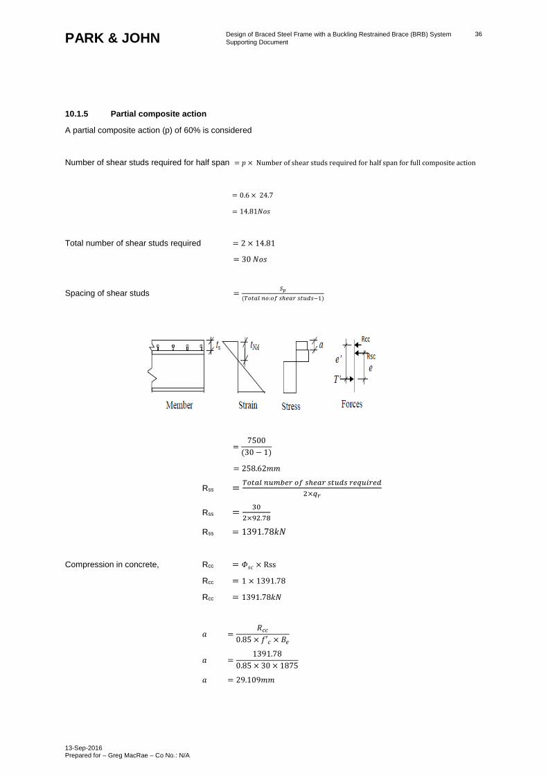
10.1.5 Partial composite action
A partial composite action (p) of 60% is considered
Number of shear studs required for half span = 𝑝 × Number of shear studs required for half span for full composite action
= 0.6 × 24.7
= 14.81𝑁𝑜𝑠
Total number of shear studs required = 2 × 14.81
= 30 𝑁𝑜𝑠
Spacing of shear studs =𝑆𝑝
(𝑇𝑜𝑡𝑎𝑙 𝑛𝑜:𝑜𝑓 𝑠ℎ𝑒𝑎𝑟 𝑠𝑡𝑢𝑑𝑠−1)
=7500
(30 − 1)
= 258.62𝑚𝑚
Rss =𝑇𝑜𝑡𝑎𝑙 𝑛𝑢𝑚𝑏𝑒𝑟 𝑜𝑓 𝑠ℎ𝑒𝑎𝑟 𝑠𝑡𝑢𝑑𝑠 𝑟𝑒𝑞𝑢𝑖𝑟𝑒𝑑
2×𝑞𝑟
Rss =30
2×92.78
Rss = 1391.78𝑘𝑁
Compression in concrete, Rcc = 𝛷𝑠𝑐 × Rss
Rcc = 1 × 1391.78
Rcc = 1391.78𝑘𝑁
𝑎 =𝑅𝑐𝑐
0.85 × 𝑓′𝑐 × 𝐵𝑒
𝑎 =1391.78
0.85 × 30 × 1875
𝑎 = 29.109𝑚𝑚
Design of Braced Steel Frame with a Buckling Restrained Brace (BRB) System
Supporting Document
13-Sep-2016 Prepared for – Greg MacRae – Co No.: N/A
37 PARK & JOHN
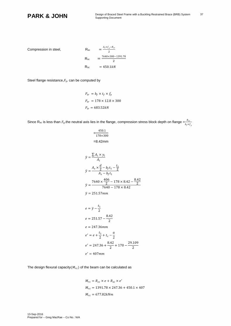
Compression in steel, Rsc =𝐴𝑠×𝑓𝑦−𝑅𝑐𝑐
2
Rsc =7640×300−1391.78
2
Rsc = 450.1𝑘𝑁
Steel flange resistance,𝐹𝑙𝑟 can be computed by
𝐹𝑙𝑟 = 𝑏𝑓 × 𝑡𝑓 × 𝑓𝑦
𝐹𝑙𝑟 = 178 × 12.8 × 300
𝐹𝑙𝑟 = 683.52𝑘𝑁
Since Rsc is less than 𝐹𝑙𝑟the neutral axis lies in the flange, compression stress block depth on flange =𝑅𝑠𝑐
𝑏𝑓×𝑓𝑦
=450.1
178×300
=8.42mm
�̅� =∑ 𝐴𝑖 × 𝑦𝑖
𝐴𝑖
�̅� =𝐴𝑠 ×
𝑑2
− 𝑏𝑓𝑡1 −𝑡12
𝐴𝑠 − 𝑏𝑓𝑡1
�̅� =7640 ×
4062
− 178 × 8.42 −8.42
27640 − 178 × 8.42
�̅� = 251.57𝑚𝑚
𝑒 = �̅� −𝑡1
2
𝑒 = 251.57 −8.42
2
𝑒 = 247.36𝑚𝑚
𝑒′ = 𝑒 +𝑡1
2+ 𝑡𝑐 −
𝑎
2
𝑒′ = 247.36 +8.42
2+ 170 −
29.109
2
𝑒′ = 407𝑚𝑚
The design flexural capacity(𝑀𝑟𝑐) of the beam can be calculated as
𝑀𝑟𝑐 = 𝑅𝑐𝑐 × 𝑒 + 𝑅𝑠𝑐 × 𝑒′
𝑀𝑟𝑐 = 1391.78 × 247.36 + 450.1 × 407
𝑀𝑟𝑐 = 677.82𝑘𝑁𝑚
Design of Braced Steel Frame with a Buckling Restrained Brace (BRB) System
Supporting Document
13-Sep-2016 Prepared for – Greg MacRae – Co No.: N/A
38 PARK & JOHN
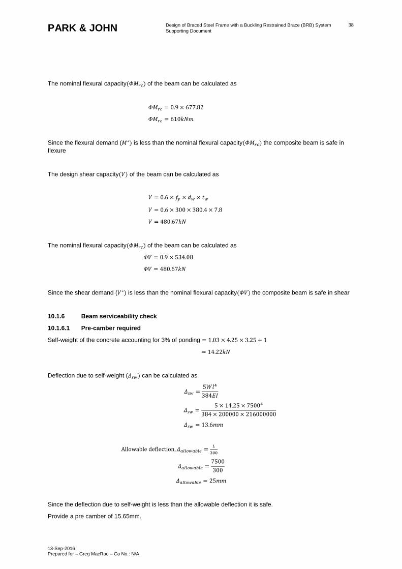
The nominal flexural capacity(𝛷𝑀𝑟𝑐) of the beam can be calculated as
𝛷𝑀𝑟𝑐 = 0.9 × 677.82
𝛷𝑀𝑟𝑐 = 610𝑘𝑁𝑚
Since the flexural demand (𝑀∗) is less than the nominal flexural capacity(𝛷𝑀𝑟𝑐) the composite beam is safe in
flexure
The design shear capacity(𝑉) of the beam can be calculated as
𝑉 = 0.6 × 𝑓𝑦 × 𝑑𝑤 × 𝑡𝑤
𝑉 = 0.6 × 300 × 380.4 × 7.8
𝑉 = 480.67𝑘𝑁
The nominal flexural capacity(𝛷𝑀𝑟𝑐) of the beam can be calculated as
𝛷𝑉 = 0.9 × 534.08
𝛷𝑉 = 480.67𝑘𝑁
Since the shear demand (𝑉∗) is less than the nominal flexural capacity(𝛷𝑉) the composite beam is safe in shear
10.1.6 Beam serviceability check
10.1.6.1 Pre-camber required
Self-weight of the concrete accounting for 3% of ponding = 1.03 × 4.25 × 3.25 + 1
= 14.22𝑘𝑁
Deflection due to self-weight (𝛥𝑠𝑤) can be calculated as
𝛥𝑠𝑤 =5𝑊𝑙4
384𝐸𝐼
𝛥𝑠𝑤 =5 × 14.25 × 75004
384 × 200000 × 216000000
𝛥𝑠𝑤 = 13.6𝑚𝑚
Allowable deflection, 𝛥𝑎𝑙𝑙𝑜𝑤𝑎𝑏𝑙𝑒 =𝐿
300
𝛥𝑎𝑙𝑙𝑜𝑤𝑎𝑏𝑙𝑒 =7500
300
𝛥𝑎𝑙𝑙𝑜𝑤𝑎𝑏𝑙𝑒 = 25𝑚𝑚
Since the deflection due to self-weight is less than the allowable deflection it is safe.
Provide a pre camber of 15.65mm.
Design of Braced Steel Frame with a Buckling Restrained Brace (BRB) System
Supporting Document
13-Sep-2016 Prepared for – Greg MacRae – Co No.: N/A
39 PARK & JOHN
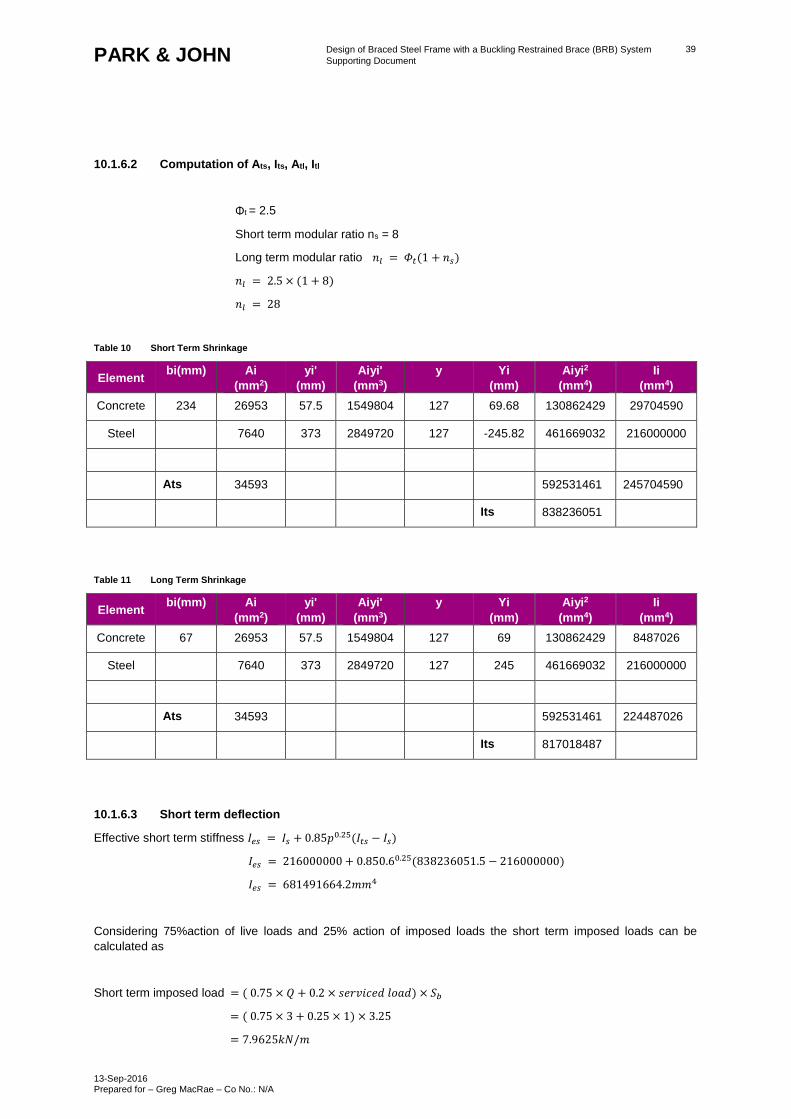
10.1.6.2 Computation of Ats, Its, Atl, Itl
Φt = 2.5
Short term modular ratio ns = 8
Long term modular ratio 𝑛𝑙 = 𝛷𝑡(1 + 𝑛𝑠)
𝑛𝑙 = 2.5 × (1 + 8)
𝑛𝑙 = 28
Table 10 Short Term Shrinkage
Element bi(mm) Ai
(mm2)
yi'
(mm)
Aiyi'
(mm3)
y Yi
(mm)
Aiyi2
(mm4)
Ii
(mm4)
Concrete 234 26953 57.5 1549804 127 69.68 130862429 29704590
Steel 7640 373 2849720 127 -245.82 461669032 216000000
Ats 34593 592531461 245704590
Its 838236051
Table 11 Long Term Shrinkage
Element bi(mm) Ai
(mm2)
yi'
(mm)
Aiyi'
(mm3)
y Yi
(mm)
Aiyi2
(mm4)
Ii
(mm4)
Concrete 67 26953 57.5 1549804 127 69 130862429 8487026
Steel 7640 373 2849720 127 245 461669032 216000000
Ats 34593 592531461 224487026
Its 817018487
10.1.6.3 Short term deflection
Effective short term stiffness 𝐼𝑒𝑠 = 𝐼𝑠 + 0.85𝑝0.25(𝐼𝑡𝑠 − 𝐼𝑠)
𝐼𝑒𝑠 = 216000000 + 0.850.60.25(838236051.5 − 216000000)
𝐼𝑒𝑠 = 681491664.2𝑚𝑚4
Considering 75%action of live loads and 25% action of imposed loads the short term imposed loads can be
calculated as
Short term imposed load = ( 0.75 × 𝑄 + 0.2 × 𝑠𝑒𝑟𝑣𝑖𝑐𝑒𝑑 𝑙𝑜𝑎𝑑) × 𝑆𝑏
= ( 0.75 × 3 + 0.25 × 1) × 3.25
= 7.9625𝑘𝑁/𝑚
Design of Braced Steel Frame with a Buckling Restrained Brace (BRB) System
Supporting Document
13-Sep-2016 Prepared for – Greg MacRae – Co No.: N/A
40 PARK & JOHN
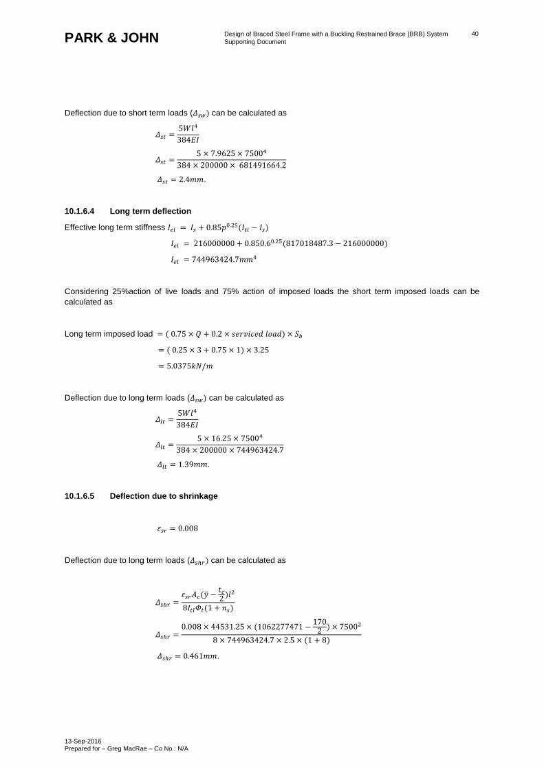
Deflection due to short term loads (𝛥𝑠𝑤) can be calculated as
𝛥𝑠𝑡 =5𝑊𝑙4
384𝐸𝐼
𝛥𝑠𝑡 =5 × 7.9625 × 75004
384 × 200000 × 681491664.2
𝛥𝑠𝑡 = 2.4𝑚𝑚.
10.1.6.4 Long term deflection
Effective long term stiffness 𝐼𝑒𝑙 = 𝐼𝑠 + 0.85𝑝0.25(𝐼𝑡𝑙 − 𝐼𝑠)
𝐼𝑒𝑙 = 216000000 + 0.850.60.25(817018487.3 − 216000000)
𝐼𝑒𝑙 = 744963424.7𝑚𝑚4
Considering 25%action of live loads and 75% action of imposed loads the short term imposed loads can be
calculated as
Long term imposed load = ( 0.75 × 𝑄 + 0.2 × 𝑠𝑒𝑟𝑣𝑖𝑐𝑒𝑑 𝑙𝑜𝑎𝑑) × 𝑆𝑏
= ( 0.25 × 3 + 0.75 × 1) × 3.25
= 5.0375𝑘𝑁/𝑚
Deflection due to long term loads (𝛥𝑠𝑤) can be calculated as
𝛥𝑙𝑡 =5𝑊𝑙4
384𝐸𝐼
𝛥𝑙𝑡 =5 × 16.25 × 75004
384 × 200000 × 744963424.7
𝛥𝑙𝑡 = 1.39𝑚𝑚.
10.1.6.5 Deflection due to shrinkage
𝜀𝑠𝑟 = 0.008
Deflection due to long term loads (𝛥𝑠ℎ𝑟) can be calculated as
𝛥𝑠ℎ𝑟 =𝜀𝑠𝑟𝐴𝑐(�̅� −
𝑡𝑐2
)𝑙2
8𝐼𝑡𝑙𝛷𝑡(1 + 𝑛𝑠)
𝛥𝑠ℎ𝑟 =0.008 × 44531.25 × (1062277471 −
1702
) × 75002
8 × 744963424.7 × 2.5 × (1 + 8)
𝛥𝑠ℎ𝑟 = 0.461𝑚𝑚.
Design of Braced Steel Frame with a Buckling Restrained Brace (BRB) System
Supporting Document
13-Sep-2016 Prepared for – Greg MacRae – Co No.: N/A
41 PARK & JOHN
10.1.6.6 Total deflection
The total deflection can be calculated as the sum of all the deflections calculated above
𝛥 = 𝛥𝑠𝑤 + 𝛥𝑠𝑡 + 𝛥𝑙𝑡 + 𝛥𝑠ℎ𝑟.
𝛥 = 13.6 + 2.4 + 1.39 + 0.461
𝛥 = 17.85𝑚𝑚.
Allowable deflection, 𝛥𝑎𝑙𝑙𝑜𝑤𝑎𝑏𝑙𝑒 =𝐿
300
𝛥𝑎𝑙𝑙𝑜𝑤𝑎𝑏𝑙𝑒 =7500
300
𝛥𝑎𝑙𝑙𝑜𝑤𝑎𝑏𝑙𝑒 = 25𝑚𝑚
Hence ok.
10.1.7 Vibration checks
In order to assess the vibration criteria of the slab we need to know its natural frequency of vibration and its peak
acceleration under a constant walking force. The natural floor frequency is assessed from the static deflection of
the floor under ambient load conditions, which requires the longitudinal floor stiffness to be calculated.
Short term imposed load = ( 0.75 × 𝑄 + 0.2 × 𝑠𝑒𝑟𝑣𝑖𝑐𝑒𝑑 𝑙𝑜𝑎𝑑) × 𝑆𝑏
= ( 0.75 × 3 + 0.25 × 1) × 3.25
= 7.9625𝑘𝑁/𝑚
Frequency of the composite floor
𝑓 = 0.18√𝐸𝐼𝑡𝑠
𝑊𝑠ℎ×𝐿4.
𝑓 = 156√20000×838236051.5
7.96×75004 .
𝑓 = 12.72𝐻𝑧
Peak acceleration of the composite floor ao
𝑎𝑜 =60𝑓
𝑤𝑝𝐵𝐿
𝐵 = 40𝑡𝑐
Average thickness of concrete floor,𝑡𝑐 =1.03×4.25×1000
24×9.81
𝑡𝑐 = 185.92𝑚𝑚
𝐵 = 40 × 185.92𝑚𝑚
𝐵 = 7.43𝑚
Design of Braced Steel Frame with a Buckling Restrained Brace (BRB) System
Supporting Document
13-Sep-2016 Prepared for – Greg MacRae – Co No.: N/A
42 PARK & JOHN
Probable weight of concrete floor,𝑤𝑝 =9.1875
3.75+ 1 + 0.5 × 3
𝑤𝑝 = 2.05
𝑎𝑜 =60 × 12.72
2.05 × 7.43 × 7.5
𝑎𝑜 = 5.46
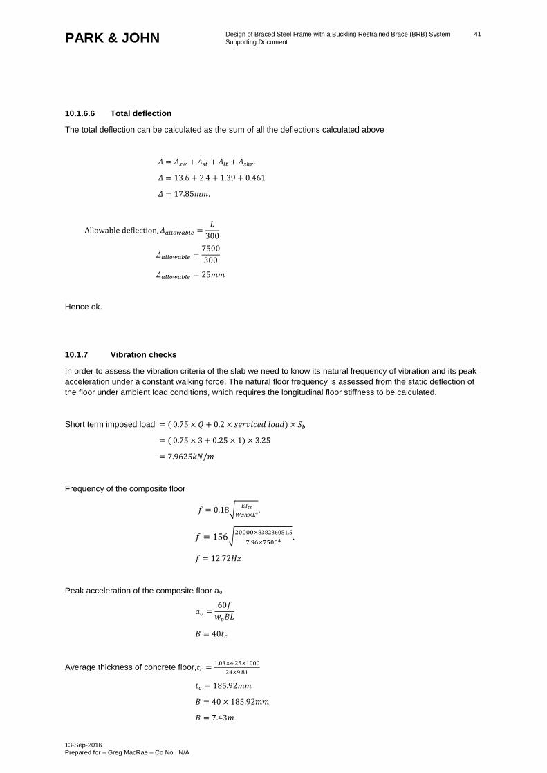
The values we have for f and 𝑎𝑜 must now be compared with the acceptable criteria of graph line C (in green) for
walking vibration shown in from figure G3 CAN/CSA. If the point plotted on this graph from these two values is
below the line C then vibration criteria are acceptable.
Damping = 6% for floors without partitions is acceptable.
Figure 17 Recommended Peak Acceleration for Human Comfort for Vibrations due to Human Activities
– AISC Floor Vibrations due to Human Activity
Design of Braced Steel Frame with a Buckling Restrained Brace (BRB) System
Supporting Document
13-Sep-2016 Prepared for – Greg MacRae – Co No.: N/A
43 PARK & JOHN
11.0 RCFT Gravity column design
11.1 Load calculation
The following were considered:
- Concrete slab thickness, 𝑡𝑐 = 170𝑚𝑚
- Dead load of the floor (G) = 4.75KPa
- Structural steel weight = 0.35 KPa
- Services load (G) = 1KPa
- Live load (Q) = 3kPa.
- Number of floors = 4
- Tributary length = 6500mm
- Tributary width = 7500mm
- Tributary area = 48750000 sqm
Axial load demand N* =1.2𝐺 + 1.5𝑄
N*= 1.2 × 5.75 + 1.5 × 3
N* = 2187.9kN
11.2 Section analysis
11.2.1 Axial capacity
The following were considered:
- Cylinder compressive strength of concrete, 𝑓′𝑐 = 30𝑀𝑝𝑎
- Assume a CHS 273.1x12.7 size outer core
- Yield strength of steel 𝑓𝑦 = 350𝑀𝑝𝑎
- Area of the section, As = 10400sqm
- Grade of longitudinal reinforcement 𝑓𝑦𝑟 = 300𝑀𝑝𝑎
- Area of longitudinal steel, Asr considering 6-12mm dia bars as longitudinal reinforcement = 678.224 sqm
Min longitudinal steel required = 0.08 𝐴𝑐
= 0.08 × 5318
= 425.49 sqm
Using rigid plastic method
Axial capacity (ΦN) = 0.9 × (0.95𝑓′𝑐𝐴𝑐 + 𝐴𝑠𝑓𝑦 + 𝐴𝑠𝑟𝑓𝑦𝑟)
(ΦN) = 0.9 × (0.95 × 5318 + 10400 × 350 + 678.224 × 300)
(ΦN) = 3595𝑘𝑁
Since the axial demand (𝑁∗) is less than the nominal flexural capacity𝛷𝑁) the composite column is safe for
gravity loads. Use 10 dia stirrups at 200mmc/c for transverse reinforcement.
Design of Braced Steel Frame with a Buckling Restrained Brace (BRB) System
Supporting Document
13-Sep-2016 Prepared for – Greg MacRae – Co No.: N/A
44 PARK & JOHN
12.0 SRC seismic column design
12.1 Nominal compressive strength calculation
- Depth of the column, d = 500mm
- Breadth of the column, b = 500mm
- Second moment of inertia of concrete
𝐼𝑐 =𝑏𝑑3
12
𝐼𝑐 =500 × 5003
12
𝐼𝑐 = 5208333333𝑚𝑚4
- Cylinder compressive strength of concrete, 𝑓′𝑐 = 30𝑀𝑝𝑎
- Area of concrete 𝐴𝑐 = 250000𝑚𝑚2
- Modulus of elasticity of concrete = 25000 Mpa
- Modulus of elasticity of steel =200000 Mpa
- Assume a section 310 UC 158
- Thickness of web (tw) = 15.7mm
- Plastic section modulus Sx = 2680000 mm3
- Second moment of Inertia of steel (Is) = 388000000 mm4
- Area of the reinforcement = 1130mm2 for 10-12 mm dia bars
- Second moment of Inertia of reinforcement (Isr) = 1017mm4
- Yield strength of steel 𝑓𝑦 = 300𝑀𝑝𝑎
- Area of the section, As = 20100sqm
From parameters for AISC LFRD column equations for SRC columns, the nominal compressive strength for
axially loaded composite column Pn can be calculated as
𝑃𝑛 = 𝑃0 [0.658𝑃𝑜𝑃𝑒]
𝑃0 = 0.85𝑓′𝑐𝐴𝑐 + 𝐴𝑠𝑓𝑦 + 𝐴𝑠𝑟𝑓𝑦𝑟
𝐸𝐼𝑒𝑓𝑓 = 𝐸𝑠𝐼𝑠 + 0.5𝐸𝑠𝑟𝐼𝑠𝑟 + 𝐶𝐸𝑐𝐼𝑐
𝐶 = 𝑚𝑖𝑛 (0.1 + 2 (𝐴𝑠
𝐴𝑠 + 𝐴𝑐) , 0.3)
𝐶 = 𝑚𝑖𝑛 ((0.1 + 2 (20100
20100 + 250000)) , 0.3)
𝐶 = 0.247
Design of Braced Steel Frame with a Buckling Restrained Brace (BRB) System
Supporting Document
13-Sep-2016 Prepared for – Greg MacRae – Co No.: N/A
45 PARK & JOHN
The effective stiffness,𝐸𝐼𝑒𝑓𝑓 can be calculated as
𝐸𝐼𝑒𝑓𝑓 = 200000 × 143000000 + 0.5 × 200000 × 3215 + 0.27 × 25000 × 1250520833
𝐸𝐼𝑒𝑓𝑓 = 1.1 × 10¹⁴
The ultimate axial load capacity Po can be calculated as
𝑃0 = 0.85 × 30 × 250000 + 20100 × 300 + 1130 × 300
𝑃0 = 12202.74𝑘𝑁
𝑃𝑒 =𝜋2𝐸𝐼𝑒𝑓𝑓
𝐿2
𝑃𝑒 =𝜋2 × 1.1 × 1014
38002
𝑃𝑒 = 75107.98𝑘𝑁
𝑃𝑛 = 𝑃0 [0.658𝑃𝑜𝑃𝑒]
𝑃𝑛 = 12202.74 [0.65812202.7475107.98]
𝑃𝑛 = 1140.52𝑘𝑁
Design of Braced Steel Frame with a Buckling Restrained Brace (BRB) System
Supporting Document
13-Sep-2016 Prepared for – Greg MacRae – Co No.: N/A
46 PARK & JOHN
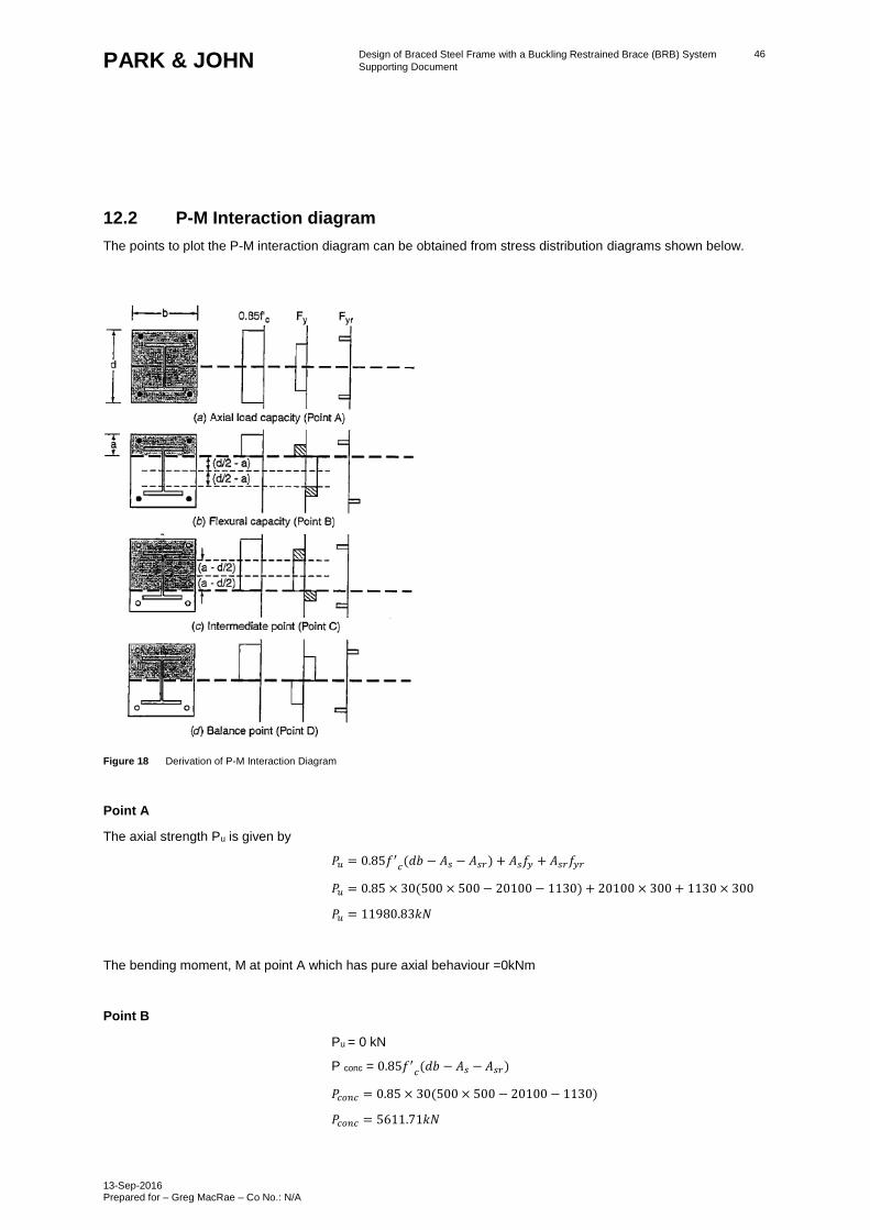
12.2 P-M Interaction diagram
The points to plot the P-M interaction diagram can be obtained from stress distribution diagrams shown below.
Figure 18 Derivation of P-M Interaction Diagram
Point A
The axial strength Pu is given by
𝑃𝑢 = 0.85𝑓′𝑐(𝑑𝑏 − 𝐴𝑠 − 𝐴𝑠𝑟) + 𝐴𝑠𝑓𝑦 + 𝐴𝑠𝑟𝑓𝑦𝑟
𝑃𝑢 = 0.85 × 30(500 × 500 − 20100 − 1130) + 20100 × 300 + 1130 × 300
𝑃𝑢 = 11980.83𝑘𝑁
The bending moment, M at point A which has pure axial behaviour =0kNm
Point B
Pu = 0 kN
P conc = 0.85𝑓′𝑐(𝑑𝑏 − 𝐴𝑠 − 𝐴𝑠𝑟)
𝑃𝑐𝑜𝑛𝑐 = 0.85 × 30(500 × 500 − 20100 − 1130)
𝑃𝑐𝑜𝑛𝑐 = 5611.71𝑘𝑁
Design of Braced Steel Frame with a Buckling Restrained Brace (BRB) System
Supporting Document
13-Sep-2016 Prepared for – Greg MacRae – Co No.: N/A
47 PARK & JOHN
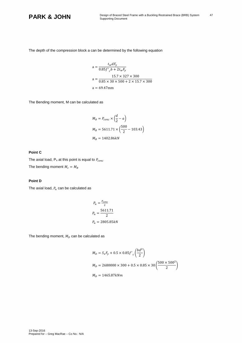
The depth of the compression block a can be determined by the following equation
a =𝑡𝑤𝑑𝐹𝑦
0.85𝑓′𝑐𝑏 + 2𝑡𝑤𝐹𝑦
a =15.7 × 327 × 300
0.85 × 30 × 500 + 2 × 15.7 × 300
a = 69.47mm
The Bending moment, M can be calculated as
𝑀𝐵 = 𝑃𝑐𝑜𝑛𝑐 × (𝑑
2− 𝑎)
𝑀𝐵 = 5611.71 × (500
2− 103.43)
𝑀𝐵 = 1402.86𝑘𝑁
Point C
The axial load, Pu at this point is equal to 𝑃𝑐𝑜𝑛𝑐
The bending moment 𝑀𝑐 = 𝑀𝐵
Point D
The axial load, 𝑃𝑢 can be calculated as
𝑃𝑢 =𝑃𝑐𝑜𝑛𝑐
2
𝑃𝑢 =5611.71
2
𝑃𝑢 = 2805.85𝑘𝑁
The bending moment, 𝑀𝐷 can be calculated as
𝑀𝐷 = 𝑆𝑥𝐹𝑦 + 0.5 × 0.85𝑓′𝑐
(𝑏𝑑2
2)
𝑀𝐷 = 2680000 × 300 + 0.5 × 0.85 × 30 (500 × 5002
2)
𝑀𝐷 = 1465.87𝑘𝑁𝑚
Design of Braced Steel Frame with a Buckling Restrained Brace (BRB) System
Supporting Document
13-Sep-2016 Prepared for – Greg MacRae – Co No.: N/A
48 PARK & JOHN
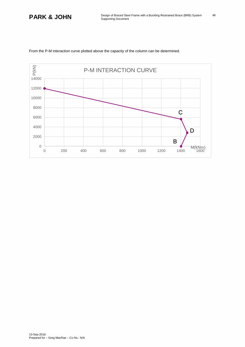
From the P-M interaction curve plotted above the capacity of the column can be determined.
0
2000
4000
6000
8000
10000
12000
14000
0 200 400 600 800 1000 1200 1400 1600
P(k
N)
M(kNm)
P-M INTERACTION CURVE
B
D
C

Design of Braced Steel Frame with a Buckling Restrained Brace (BRB) System
Supporting Document
13-Sep-2016 Prepared for – Greg MacRae – Co No.: N/A
49 PARK & JOHN
13.0 Results Summary
13.1 Non-Composite Design
Table 12 Non-Composite Design: Summary of Member Demands and Capacities
Item Demand (kN, kNm) Capacity (kN, kNm) Demand to Capacity
Ratio
Beam
(310 UC 96.8)
Axial: 1500
Axial: 2140
Axial: 0.70
Column
(310 UC 158)
Axial: 3500
Shear: 30
Moment: 70
Axial: 4280
Shear: 832
Moment: 614
Axial: 0.82
Shear: 0.04
Moment: 0.11
BRB
(Star Seismic 13.5)
Axial: 2300 Axial: 2700 Axial: 0.85
BRB
(Star Seismic 16.5)
Axial: 3100 Axial: 3300 Axial: 0.94
13.2 Composite Design
Table 13 Composite Design: Summary of Member Demands and Capacities
Item Demand (kN, kNm) Capacity (kN, kNm) Demand to Capacity
Ratio
Gravity Beam
(410 UB 59.7)
Shear: 132
Moment: 247
Shear: 481
Moment: 800
Shear: 0.27
Moment: 0.31
Gravity Column
(RCFT CHS 273X12.7)
Axial: 2190
Axial: 3595
Axial: 0.61
BRB
(Star Seismic 13.5)
Axial: 2240 Axial: 2700 Axial: 0.83
BRB
(Star Seismic 16.5)
Axial: 3000 Axial: 3300 Axial: 0.91
Seismic Beam
(310 UC 96.8)
Axial: 1400
Axial: 2140
Axial: 0.65
Seismic Column
(310 UC 158 with
500mm x 500mm
concrete encasement)
Axial: 3500
Axial: 10000
Axial: 0.35
Diaphragm
(170mm thick Dimond
Hibond Composite
Flooring)
Compression: 980
Tension: 670
Compression: 1300
Tension: 785
Compression: 0.75
Tension: 0.85
Recommended