Hardware Reference Manual Version 1.12
Figure 1 VMX-pi configured with Raspberry Pi 3

VMX-pi Hardware Reference Manual (version 1.10) 2
Contents Feature Summary ...................................................................................................................................... 3
Technical Specifications ............................................................................................................................ 5
I/O Summary ............................................................................................................................................. 8
I/O Resource Summary ........................................................................................................................... 10
Channel/Resource Routing ................................................................................................................. 10
I/O Channel Types/Numbers .................................................................................................................. 11
High Current DIO Input/Output Selection Jumper ............................................................................. 12
Power Management Scheme .................................................................................................................. 13
VMX-pi Power Management ............................................................................................................... 14
External Device Power/Signal Voltage Configuration ............................................................................. 16
Signal Voltage Select Jumpers ............................................................................................................. 16
Power Voltage Select Jumpers ............................................................................................................ 16
VMX-pi I/O Signal/Logic Levels ............................................................................................................... 16
Board-edge Connectors .......................................................................................................................... 18
FlexDIO Connectors (VMX Channels 0-7) ............................................................................................ 18
FlexDIO Header (VMX Channels 8-11) ................................................................................................ 19
High-Current DIO Header (VMX Channels 12-21) ............................................................................... 19
Analog Input Header (VMX Channels 22-25) ...................................................................................... 20
CommDIO Connectors (VMX Channels 26-33) ................................................................................... 21
CAN Connector .................................................................................................................................... 21
CAN Termination Jumper .................................................................................................................... 21
Micro-USB Connector ......................................................................................................................... 22
Input Power Connector ....................................................................................................................... 22
Battery & Real-time Clock ....................................................................................................................... 22
40-pin Raspberry Pi Connector ............................................................................................................... 23
Optional 5V Fan Connector ..................................................................................................................... 23
LEDs ......................................................................................................................................................... 23
Buttons .................................................................................................................................................... 24
Physical Dimensions ................................................................................................................................ 25

VMX-pi Hardware Reference Manual (version 1.10) 3
Feature Summary VMX-pi is designed to control a reliable, intelligent robot that is tele-operated, semi-autonomous or
fully-autonomous – when combined with an inexpensive Raspberry Pi-based processor. VMX-pi is also
usable as a Vision/Motion co-processor when paired with another robot controller.
The current recommended Raspberry Pi model is the “Raspberry Pi 4B” or the “Raspberry Pi 3B+”
(shown in picture on the cover page of this document); the Raspberry Pi Zero W may also be used
although it provides only a subset of the Raspberry Pi 4B and 3B+ capabilities.
1 to 4 GB DDR RAM
4-core 1.5Ghz 64-bit ARM Cortex-A72
Bluetooth5
HDMI (4-k Capable)
1Gbps Ethernet
Networking
2.4 & 5Ghz 802.11n Wifi
Broadcom VideoCore VI
GPU (500Mhz)
Raspberry Pi 4B
2 USB 3.0, 2USB 2.0
Ports
SD Card
VMX-pi + Raspberry Pi 4 Key Components
CSI Camera Interface
USB Data/Config Port
100Mhz 32-bit ARM
Cortex-M4 w/FPU
9-axis Inertial Sensor/Motion
Processor
Voltage Regulator w/5 and 3.3V
Outputs
VMX-pi
Barometer (optional)
Battery-backed Realtime Clock
30 Digital I/Os4 Analog I/Os;SPI, I2C, TTL
UART
CAN Interface
External Device Current-limiting
Figure 2 VMX-pi & Raspberry Pi Key Components

VMX-pi Hardware Reference Manual (version 1.10) 4
Component Function Key Attributes
Voltage Regulator w/wide input voltage range
Converts unregulated 6-16VDC to 5V & 3.3V, up to a maximum of 3A; includes real-time under-voltage management
Can provide 2.1A to Raspberry Pi and .5A to external devices at input voltages as low as 6VDC
External Device Current Limiting Switch & Short-circuit protection
External 5/3.3V supplies are current limited at .5A, to ensure full power is always provided to the Raspberry Pi processor and VMX-pi microcontroller
Processors continue running even when external devices draw excessive power or when short-circuits occur
5/3.3V Voltage Translation
Flexibly supports signaling with 5V and 3.3V external devices
Eliminates need for external voltage translation devices
Battery-backed Real-time Clock (RTC)
When VMX-pi is used in environments without Network Time Server access, provides real-time clock for distributed sensor data alignment and accurate log timestamps
Can be populated with a CR2032 battery w/expected life of 5 years before replacement
100Mhz 32-bit ARM-M4 w/FPU Microcontroller (STM32F411)
Implements real-time IO and timer functions, IMU sensor data fusion, CAN bus message buffering and Power/Brownout Management
Field-upgradable firmware can be updated w/new features and bugfixes
30 Digital I/Os with overvoltage protection
Flexible digital IO support including PWM Generation on outputs, PWM Capture, Quad Encoder decode, Interrupt Generation on inputs
• PWM Generation on all outputs
• PWM Capture on “FlexIO” inputs
• Interrupt Generation on all inputs
• Quadrature Encoder decode on 5 pairs of “FlexIO” inputs
4 Analog I/Os with overvoltage protection
12-bit ADC providing 46.5k samples/sec on each channel
Over-sampling and Averaging Engine; Analog Triggering supporting Interrupt generation on Analog Inputs
CAN Interface CAN 2.0b transceiver and controller supporting message transmission/reception and filtering
1 mbps bus data rate supported
9-axis Inertial Sensor/Motion Processor
Generates Yaw/Pitch/Roll measures as well as Quaternions and raw gyro/accelerometer/ magnetometer data; also includes automatic calibration software w/flash-based storage of calibration data
Invensense MPU-9250 and navX-Technology Kauai Labs firmware
I2C Support 2 Comm DIO Channels can be configured for I2C communication w/built-in pullup resistors
400Khz I2C communication supported
TTL UART Support 2 Comm DIO Channels can be configured for TTL UART communication
115.2 kbps UART communication supported
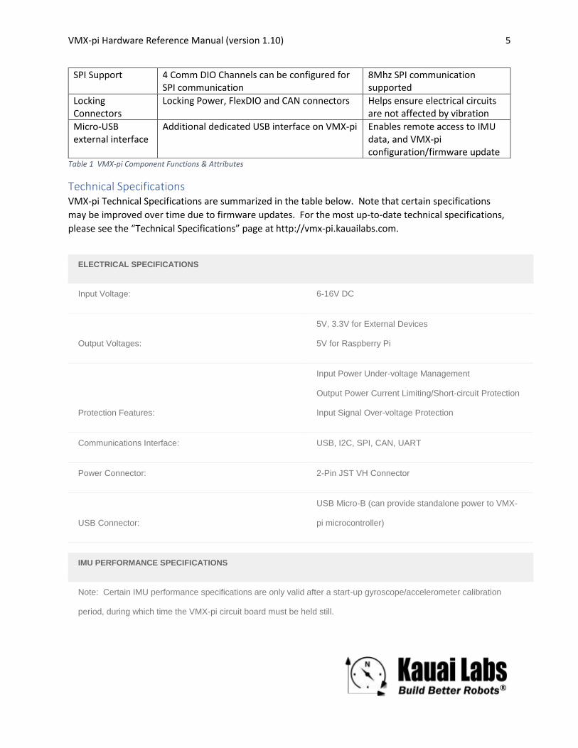
VMX-pi Hardware Reference Manual (version 1.10) 5
Table 1 VMX-pi Component Functions & Attributes
Technical Specifications VMX-pi Technical Specifications are summarized in the table below. Note that certain specifications
may be improved over time due to firmware updates. For the most up-to-date technical specifications,
please see the “Technical Specifications” page at http://vmx-pi.kauailabs.com.
ELECTRICAL SPECIFICATIONS
Input Voltage: 6-16V DC
Output Voltages:
5V, 3.3V for External Devices
5V for Raspberry Pi
Protection Features:
Input Power Under-voltage Management
Output Power Current Limiting/Short-circuit Protection
Input Signal Over-voltage Protection
Communications Interface: USB, I2C, SPI, CAN, UART
Power Connector: 2-Pin JST VH Connector
USB Connector:
USB Micro-B (can provide standalone power to VMX-
pi microcontroller)
IMU PERFORMANCE SPECIFICATIONS
Note: Certain IMU performance specifications are only valid after a start-up gyroscope/accelerometer calibration
period, during which time the VMX-pi circuit board must be held still.
SPI Support 4 Comm DIO Channels can be configured for SPI communication
8Mhz SPI communication supported
Locking Connectors
Locking Power, FlexDIO and CAN connectors Helps ensure electrical circuits are not affected by vibration
Micro-USB external interface
Additional dedicated USB interface on VMX-pi Enables remote access to IMU data, and VMX-pi configuration/firmware update

VMX-pi Hardware Reference Manual (version 1.10) 6
Startup Calibration Period: 15 seconds
Gyro Sensitivity: +/- 2000 degrees/sec
Accel Sensitivity: +/- 2 g
Magnetometer Sensitivity: 1.3 Gauss
Yaw angle accuracy: ~1 degree of drift/minute
Yaw angle accuracy (when still): ~.25 degree of drift/minute
Orientation Data Update Rate: 4-100 Hz
Magnetometer Raw Update Rate: 4 Hz
Magnetometer Angular Accuracy: +/- 2 degrees
Pitch/Roll Angular Accuracy: +/- 1.5 degrees
ANALOG INPUT SPECIFICATIONS
Number of Channels: 4
Resolution: 12 bits
Per-channel Sampling Rate: 46.5K samples/sec
DIGITAL IO SPECIFICATIONS
Total Number of Channels: 30
Number of Input-capable & Interrupt-capable Channels: 26
Number of Output-capable & PWM-capable Channels: 28

VMX-pi Hardware Reference Manual (version 1.10) 7
Number of Quadrature Encoder Channel Pairs
(Hardware-decode): 5
Number of PWM Capture Inputs 6
DIGITAL COMMUNICATION SPECIFICATIONS
CAN Protocol (2.0b) 1mbps (also supports 500kbps and 250kbps)
SPI Protocol 8 Mhz
I2C Protocol 400 kHz
USB Protocol v. 3.0 (5 Gbps)
UART Protocol 115,200 bps

VMX-pi Hardware Reference Manual (version 1.10) 8
I/O Summary
High-Current DIO(PWM/Relay/Digital Output
or Input)[5 or 3.3V]
10
Analog Inputs(12-bit
resolution)[5 or 3.3V]
CAN I2C (or 2 DO or 2DI
w/pullups)
SPI (or 3 DO, 1DI)
TTL UART(or 1 DO, 1DI)
HW Quadrature Decode (Max 5 Pair [10 pins])
PWM/Digital IOs (Max 12)
150mA Analog Supply
Up to 400mA Digital Supply
FlexDIO
124
VMX-pi I/O Summary
3.3 V (5V Tolerant inputs)
• 30 Digital I/O Channels - “FlexDIOs PWM-capable, H/W decode of 5 Quadrature Encoders - “High Current DIOs either all inputs or all PWM-capable outputs - “Comm DIOs PWM-capable outputs, 4 inputs) supporting SPI, I2C and UART or Digital I/O functions• 4 Analog Input Channels• Dedicated CAN Interface
Comm DIO [5 or 3.3V]
Figure 3 VMX-pi IO Summary
FlexDIO Channels: These channels drive 3.3V, are 5V tolerant when used as inputs, and each channel is
individually software configurable as input or output channel. FlexDIO channels have a lower output
current drive than other channel types, and support advanced timer functions including decoding of
signals from quadrature encoders.
High-Current DIO Channels: These channels drive 3.3V or 5V (jumper-configurable), and are jumper-
configurable to be either all inputs or all outputs. High-Current DIO channels provided enhanced
current-drive capabilities allowing them to be used to drive relays as well as motor controllers.
Analog Input Channels: These channels accept 3.3V or 5V input signals.
Comm DIO Channels: These channels drive 3.3V or 5V (jumper-configurable); some are fixed as input
channels, and some are as fixed output channels. These channels support a medium-current drive
capability to support communication across extended distances, subject to the restrictions of each
protocol; these channels are designed to support high-bandwidth communication rates.
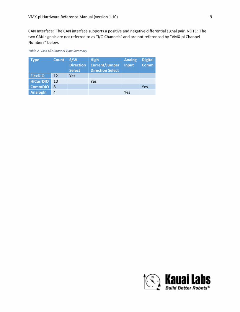
VMX-pi Hardware Reference Manual (version 1.10) 9
CAN Interface: The CAN interface supports a positive and negative differential signal pair. NOTE: The
two CAN signals are not referred to as “I/O Channels” and are not referenced by “VMX-pi Channel
Numbers” below.
Table 2 VMX I/O Channel Type Summary
Type Count S/W Direction Select
High Current/Jumper Direction Select
Analog Input
Digital Comm
FlexDIO 12 Yes
HiCurrDIO 10 Yes
CommDIO 8 Yes
AnalogIn 4 Yes

VMX-pi Hardware Reference Manual (version 1.10) 10
I/O Resource Summary Each VMX-pi channel can be used for multiple functions. This flexibility functionality is provided by a set
of I/O Resources. Each VMX-pi channel may be routed (under software control) to different I/O
resources, depending upon the VMX-pi application requirements.
Type Description Typical Use
Digital Input Detects current signal digital level (high/low)
Reading state of a button
Digital Output Transmits current signal digital level (high/low)
Triggering a Relay
PWM Generator Transmits periodic pulses with configurable period and pulse-width
Controlling a motor or servo
PWM Capture Measures pulse with (frequency and duty cycle) of periodic pulses
Reading current pulse width from servo controller
Interrupt Generates Interrupts on selected signal edge transitions
Counting “ticks” of an ultrasonic distance sensor
Accumulator Performs Oversampling/Averaging on an Analog Input
Noise-removal and resolution enhancement on inputs from an analog potentiometer
Analog Trigger Generates Interrupts on analog input high/low level transitions
Counting “ticks” of an analog sensor input
UART TX/RX line data transceiver Communication with an external GPS
SPI CLK/MOSI/MISO/CS line data transceiver Communication with an external IMU sensor
I2C SCL/SDA line data transceiver Communication with an external LIDAR sensor
Table 3 VMX-pi Resource Summary
Many I/O Resource Types support a single I/O Channel; certain Resource Types may support more than
1 channel (e.g., a Quadrature Encoder Resource supports two I/O Channels, one for the A signal and
another for the B signal).
Channel/Resource Routing To use an I/O Resource, one or more I/O Channels must be routed to the resource. Each I/O Channel
Type may be routed to the following I/O Resources:
Type DIO/ PWM
Encoder
PWM Capture
Interrupt Accumulator Analog Trigger
UART SPI I2C
# Chan per Resource
1 2 1 1 1 1 2 4 2
FlexDIO Yes Yes Yes Yes
HiCurrDIO Yes Yes
VMX-pi Hardware Reference Manual (version 1.10) 11
CommDIO Yes Yes Yes Yes Yes
AnalogIn Yes Yes Yes
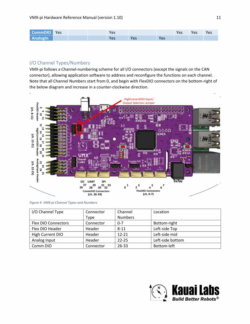
I/O Channel Types/Numbers VMX-pi follows a Channel-numbering scheme for all I/O connectors (except the signals on the CAN
connector), allowing application software to address and reconfigure the functions on each channel.
Note that all Channel Numbers start from 0, and begin with FlexDIO connectors on the bottom-right of
the below diagram and increase in a counter-clockwise direction.
01
23
45
67
89
1011
1213
1415
1617
1819
2021
2223
2425
2627
2829
3031
3233
FlexDIO Connectors
FlexDIO
Head
erH
ighCu
rrentD
IO H
eader
An
alogInp
ut Head
er
CommDIO Connectors
I2C UART SPI
(ch. 8-11)
(ch. 0-7)(ch. 26-33)
(ch. 12-21)
(ch. 22-25)
HighCurrentDIO Input/Output Selection Jumper
Figure 4 VMX-pi Channel Types and Numbers
I/O Channel Type Connector Type
Channel Numbers
Location
Flex DIO Connectors Connector 0-7 Bottom-right
Flex DIO Header Header 8-11 Left-side Top
High Current DIO Header 12-21 Left-side mid
Analog Input Header 22-25 Left-side bottom
Comm DIO Connector 26-33 Bottom-left

VMX-pi Hardware Reference Manual (version 1.10) 12
High Current DIO Input/Output Selection Jumper The entire bank of High Current DIOs can be either all inputs, or all outputs. This selection is performed
in hardware via the High Current DIO Input/Output Selection Jumper. If the jumper is present, all High
Current DIOs function as outputs, otherwise they function as inputs.

VMX-pi Hardware Reference Manual (version 1.10) 13
Power Management Scheme To minimize the number of system components, VMX-pi provides integrated voltage regulators; the
input power source may be a wide range of DC input voltages (e.g., from a battery) and outputs 5VDC to
the Raspberry Pi, as well as 5VDC and 3.3V DC External Devices.
Buck Regulator(3A)
6-16VDC (unregulated)
RPi-4, Rpi-3 or RPi ZeroW
5VDC
CAN Controller/Transceiver
Max 2.1A
Max 120mA (CANL Short condition)
Internal 3.3V Digital LDO
(200mA Limt)uC
Max 180mA
Onboard Sensors
Max 25mA
Max 50mA
Current Limiting Switch(Max 500mA)
Max 500mA
Internal Analog LDO/OpAmp (3.3V, 30 mA)
External I/OVoltage LDO (3.3V, Max
500mA)
ADC
Max 10mA
CurrentFault
Indicator
3.3VDC
(Max 500mACombined)
VMX-pi Power Tree(Max Power Consumption: 15W)
LEDsMax 35mA
Max 48mAExternal IOs
VMX-pi is powered by a single 6-16VDC unregulated voltage source, and the devices it powers may
consume up to 3 Amps (15 Watts). The VMX-pi voltage regulators are designed to output the following
maximum current levels:
Max. Current Purpose
2.1 Amps Raspberry Pi Processor & USB peripheral power
.4 Amps VMX-pi microcontroller and onboard circuitry power (including IMU, CAN and signal-driving circuitry)
.5 Amps VMX-pi External Device power

VMX-pi Hardware Reference Manual (version 1.10) 14
VMX-pi Power Management VMX-pi Power Management ensures reasonable system behavior in exceptional events including Input
Power under-voltage, and also external device power over-current and short-circuit conditions.
External Device Over-current and short-circuit management
When the VMX-pi 5V and 3.3V regulators that provide power to External Devices detect a current draw
from those external devices exceeding the maximum current level (.5A), current is either limited to the
maximum, or alternatively the current is completely removed, depending upon software configuration.
This design ensures that sufficient power is reserved for proper operation of the VMX-pi microcontroller
and the Raspberry Pi processor and its USB peripherals - even when External Device short-circuit
conditions occur.
Input Power under-voltage management
In Input Power under-voltage situations, VMX-pi is designed to preserve power to the VMX-pi
microcontroller and the Raspberry Pi processor, at the expense of any peripherals which may be
attached. Specifically, VMX-pi’s power management scheme prioritizes the Raspberry PI power supply
first, then the VMX-pi microcontroller second, and lowest priority is given to any External Devices. This
design ensures that critical components are able to maintain state (e.g., software algorithms, IMU
calibration coefficients, or buffers of recently received CAN packets).
Figure 5 VMX-pi power supply voltage regulator dropout curve
As shown in the VMX-pi voltage regulator dropout curve above, the VMX-pi voltage regulator can
guarantee the full 3A (15W) power output as long the Input Power voltage is above 5.75V.
The Raspberry Pi 3 USB power supply – which is designed to power external USB devices - will brown out
when the VMX-pi 5V voltage regulator output drops below 4.75V. At the maximum 3A load, this
corresponds to a VMX-pi input voltage of 5.75V. For a more typical lightly-loaded Raspberry Pi
consuming 1A, this corresponds to a minimum input voltage of 5V. Note also that the Raspberry Pi
processor will continue to function until the VMX-pi input voltage reaches 4.5V, and the VMX-pi
VMX-pi Hardware Reference Manual (version 1.10) 15
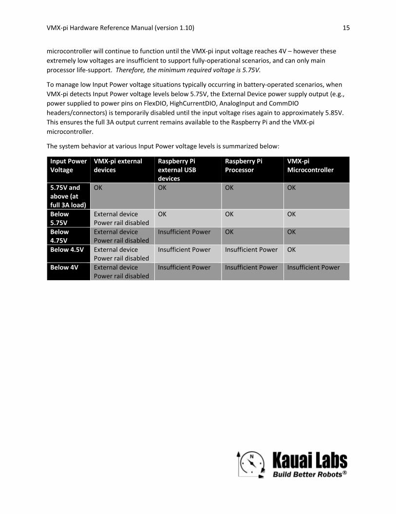
microcontroller will continue to function until the VMX-pi input voltage reaches 4V – however these
extremely low voltages are insufficient to support fully-operational scenarios, and can only main
processor life-support. Therefore, the minimum required voltage is 5.75V.
To manage low Input Power voltage situations typically occurring in battery-operated scenarios, when
VMX-pi detects Input Power voltage levels below 5.75V, the External Device power supply output (e.g.,
power supplied to power pins on FlexDIO, HighCurrentDIO, AnalogInput and CommDIO
headers/connectors) is temporarily disabled until the input voltage rises again to approximately 5.85V.
This ensures the full 3A output current remains available to the Raspberry Pi and the VMX-pi
microcontroller.
The system behavior at various Input Power voltage levels is summarized below:
Input Power Voltage
VMX-pi external devices
Raspberry Pi external USB devices
Raspberry Pi Processor
VMX-pi Microcontroller
5.75V and above (at full 3A load)
OK OK OK OK
Below 5.75V
External device Power rail disabled
OK OK OK
Below 4.75V
External device Power rail disabled
Insufficient Power OK OK
Below 4.5V External device Power rail disabled
Insufficient Power Insufficient Power OK
Below 4V External device Power rail disabled
Insufficient Power Insufficient Power Insufficient Power

VMX-pi Hardware Reference Manual (version 1.10) 16
External Device Power/Signal Voltage Configuration VMX-pi provides flexibility in the voltage used to power and exchange signals with External Devices.
Several onboard jumpers allow various configurations to address many system configurations, typically
eliminating the need for external voltage translation devices.
High Current DIO Power/
Signal Voltage Select
Analog Input Power
Voltage Select
COMM/DIO Power/Signal
Voltage Select
FlexDIO Power
Voltage Select
Figure 6 VMX-pi Signal/Power Voltage Select Jumpers
Signal Voltage Select Jumpers Either 5 or 3.3V output signal levels may be selected for High Current and Comm DIOs.
Note 1: Flex DIOs are fixed at 3.3V output levels.
Note 2: All inputs are tolerant of higher voltages, see Table 5 below.
Power Voltage Select Jumpers Either 5 or 3.3V power output for external devices may be selected for Flex, High Current and Comm
DIOs and also for power pins on the Analog Input block
VMX-pi I/O Signal/Logic Levels VMX-pi Analog and Digital I/O channels are designed to support nominal signal levels in both 3.3V and
5V systems, and also include circuit protection circuitry to handle cases when input signal levels exceed
the expected range.

VMX-pi Hardware Reference Manual (version 1.10) 17
Table 4 Digital Channel output signal drive current summary
Channel Type Max. Drive Current
FlexDIO 4mA (@3.3V)
High-Current DIO 12mA (@5V)
CommDIO 10mA (@3.3V)
CAN 45mA
Table 5 Analog/Digital Input Channel signal over-voltage protection summary
Channel Type Vmax(DC)
FlexDIO 12V
High-Current DIO 12V
Analog Inputs 12V (Vmin = -12V)
CommDIO 6V
CAN 58V
Table 6 Digital Channel signal Logic Level summary
Channel Type Input/Output Logic Levels
Output V maxLow/minHigh
FlexDIO 3.3V TTL/CMOS 0.4V, 2.4V @4mA [3.3V]
High-Current DIO 3.3V/5V CMOS 0.24V, 4.75v @1mA [5V mode]
CommDIO 3.3V/5V CMOS 1.5V, 3.3V @4mA [5V mode] .8V, 2V @4mA [3.3V mode]
Table 7 Digital Channel Pull-up/Pull-down resistance summary
Channel Type Pull Direction Resistance
FlexDIO Up, Down or Floating (s/w selectable)
50k-ohm
High-Current DIO Pull-down 40k-ohm
CommDIO I2C (when used as input)
Pull-up 2.2k-ohm
CommDIO (UART when used as a digital input channel)
Floating n/a
CommDIO SPI (when used as a digital input channel)
Floating n/a
Note that CommDIO input signals are floating in support of high-bandwidth communications. In certain
applications, external pull-up resistors may be used but are not typically required.

VMX-pi Hardware Reference Manual (version 1.10) 18
Board-edge Connectors VMX-pi connectors are oriented at right-angles to the circuit board. Many of the connectors use locking
connectors to ensure reliable connectivity.
Flex DIO
4 *No Power/Gnd on SPI connector
CAN
1
Power
1
VMX-pi External IO Connector Summary(NOTE: All connectors exit at right-angle from board)
I2C, UART, 4QuadEnc
(or DIO)
6
SPI* (or DIO)
1
3-pin PWM Header (.1" pitch)
High-Current
DIO
10
Analog In
4
JST VH locking connector (2-wire, 16-22 AWG [max
10 Amp], 3.5mm pitch)
Weidmuller 2-pin Push-in Direct Insert lock
connector (3.5mm pitch)
L H
JST GH locking connector (4-wire, 26-30 AWG [max 1 Amp], 1.25mm
pitch)
CommDIOFlex DIO
Note: Power cables and JSG GH cables and associated breakout boards are available at the Kauai Labs
online store (www.kauailabs.com/store).
FlexDIO Connectors (VMX Channels 0-7) FlexDIO Connectors are a set of four locking JST GH connectors (4 pins each) with power, ground, signal
A and signal B on each connector. These connectors are designed to support Quadrature Encoders, but
may also be configured for use as Digital Inputs, Interrupts, Digital Outputs, PWM Generation or PWM
Capture.
VMX-pi Hardware Reference Manual (version 1.10) 19
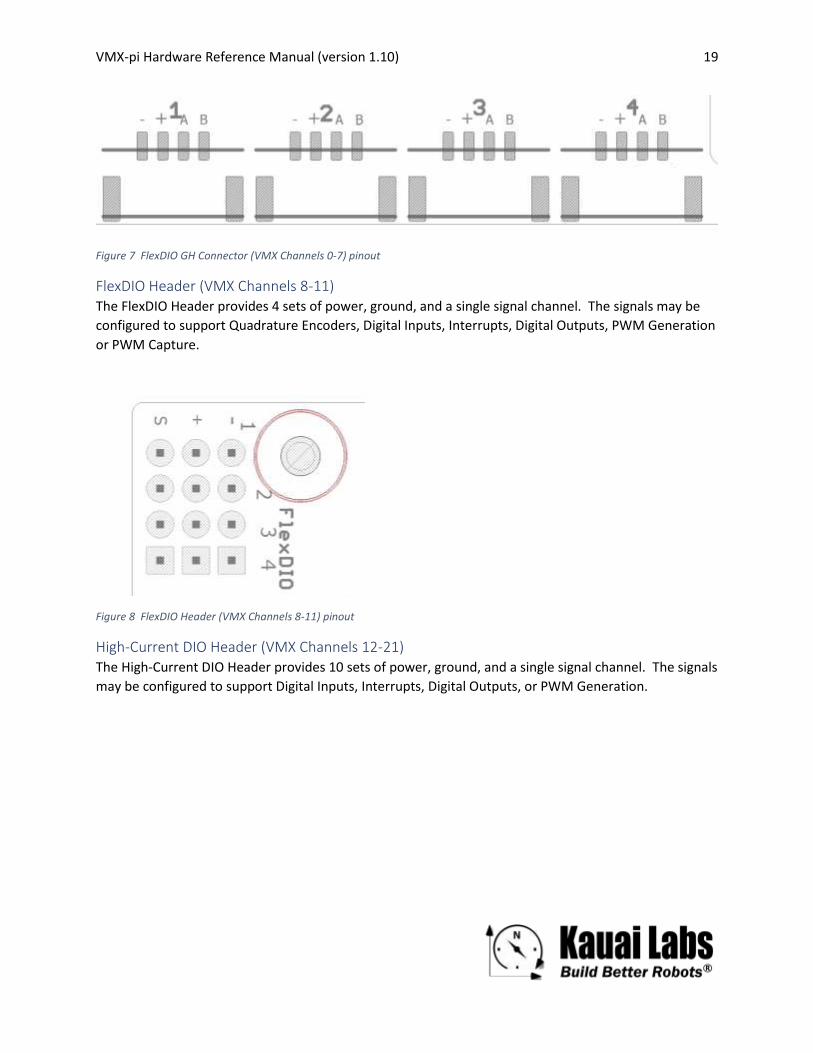
Figure 7 FlexDIO GH Connector (VMX Channels 0-7) pinout
FlexDIO Header (VMX Channels 8-11) The FlexDIO Header provides 4 sets of power, ground, and a single signal channel. The signals may be
configured to support Quadrature Encoders, Digital Inputs, Interrupts, Digital Outputs, PWM Generation
or PWM Capture.
Figure 8 FlexDIO Header (VMX Channels 8-11) pinout
High-Current DIO Header (VMX Channels 12-21) The High-Current DIO Header provides 10 sets of power, ground, and a single signal channel. The signals
may be configured to support Digital Inputs, Interrupts, Digital Outputs, or PWM Generation.
VMX-pi Hardware Reference Manual (version 1.10) 20
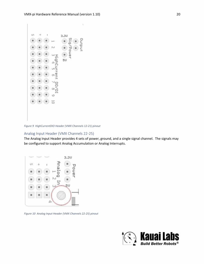
Figure 9 HighCurrentDIO Header (VMX Channels 12-21) pinout
Analog Input Header (VMX Channels 22-25) The Analog Input Header provides 4 sets of power, ground, and a single signal channel. The signals may
be configured to support Analog Accumulation or Analog Interrupts.
Figure 10 Analog Input Header (VMX Channels 22-25) pinout

VMX-pi Hardware Reference Manual (version 1.10) 21
CommDIO Connectors (VMX Channels 26-33) The 3 CommDIO Connectrors are three locking JST GH connectors (4 pins each) with different sets of
power/ground/signals. Each connector may be configured to communication using the corresponding
digital communication protocol. Alternatively, the Input Channels may be configured for use as Digital
Inputs or Interrupts; Output Channels may be configured for use as Digital Outputs or PWM.
Pin 1 Pin 2 Pin 3 Pin 4
I2C Ground Power (5 or 3.3V) SDA (Channel 26) [OUTPUT]
SCL (Channel 27) [OUTPUT]
UART Ground Power (5 or 3.3V) TX (Channel 28) [OUTPUT]
RX (Channel 29) [INPUT]
SPI SCK (Channel 30) [OUTPUT]
MOSI (Channel 31) [OUTPUT]
MISO (Channel 32) [INPUT]
CS (Channel 33) [OUTPUT]
Figure 11 CommDIO Connector (VMX Channels 26-33) pinout
CAN Connector The CAN Connector is a 2-pin Weidmuller Push-in Direct Insert Lock Connectors designed to connect to
the CAN Low (L) and CAN High (H) signals.
s
Figure 12 CAN Connector and CAN 10KOhm Termination Header
CAN Termination Jumper A CAN Termination Jumper is also provided; when a jumper is installed, a 10K-ohm resistor is enabled in
order to provide CAN bus termination.

VMX-pi Hardware Reference Manual (version 1.10) 22
Micro-USB Connector A Micro-USB Connector is provided allowing for both remote configuration/management (including
firmware upgrade) as well as access to a real-time data stream (up to 200Hz) from the onboard navX-
technology IMU.
Figure 13 Micro-USB Connector
Input Power Connector A JST VH Locking Connector provides power to the circuit board, as well as the connected Raspberry Pi
and any external devices. The connector is rated for 10A, which well exceeds the VMX-pi current limit of
3A.
Battery & Real-time Clock VMX-pi includes a pre-installed CR2032 3V Battery and associated Real-time Clock, enabling VMX-pi to
manage a date/time clock (with 500 microsecond resolution) which can be used to timestamp logs,
provide a network clock source in systems where an accurate time source is not present, and to
synchronize sensor data from multiple sources.
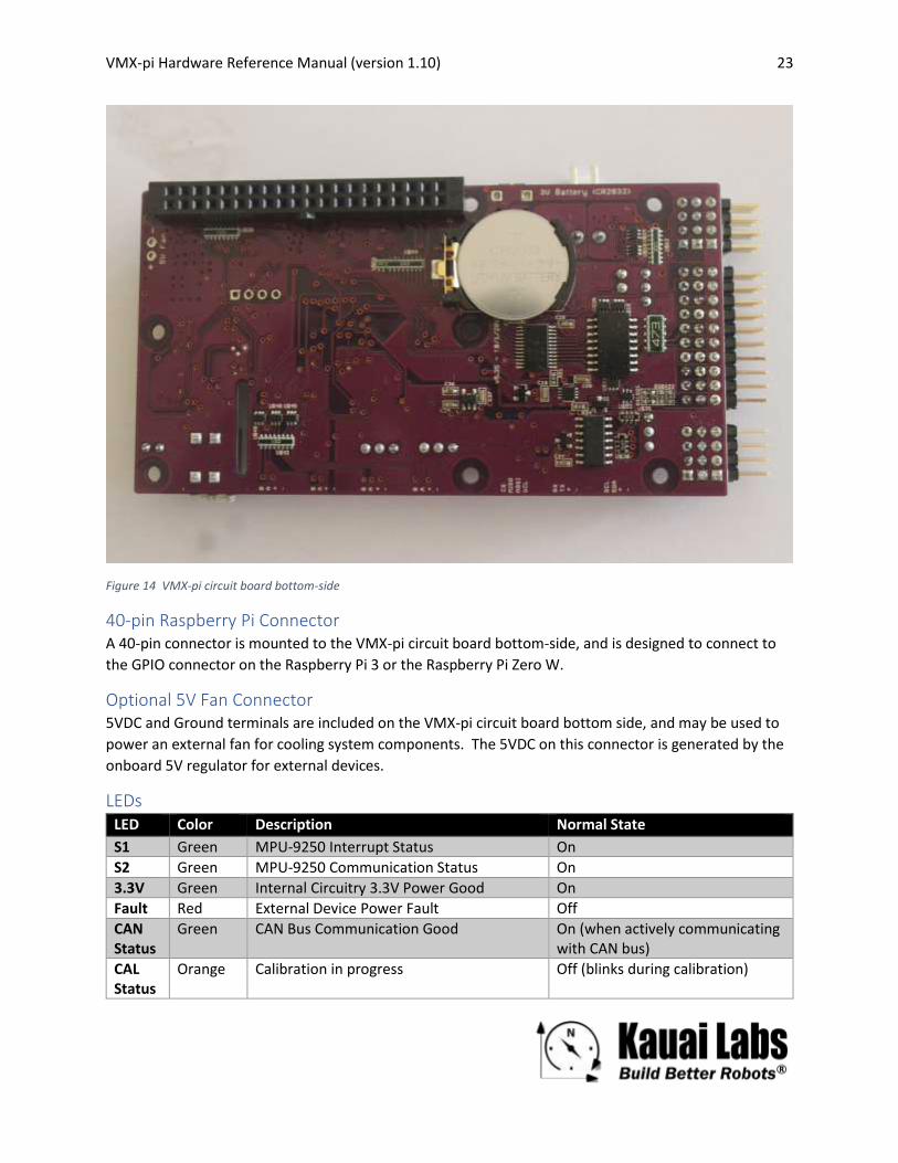
The Battery is installed on the under-side of the circuit board, as shown in Figure 14.
VMX-pi Hardware Reference Manual (version 1.10) 23
Figure 14 VMX-pi circuit board bottom-side
40-pin Raspberry Pi Connector A 40-pin connector is mounted to the VMX-pi circuit board bottom-side, and is designed to connect to
the GPIO connector on the Raspberry Pi 3 or the Raspberry Pi Zero W.
Optional 5V Fan Connector 5VDC and Ground terminals are included on the VMX-pi circuit board bottom side, and may be used to
power an external fan for cooling system components. The 5VDC on this connector is generated by the
onboard 5V regulator for external devices.
LEDs LED Color Description Normal State
S1 Green MPU-9250 Interrupt Status On
S2 Green MPU-9250 Communication Status On
3.3V Green Internal Circuitry 3.3V Power Good On
Fault Red External Device Power Fault Off
CAN Status
Green CAN Bus Communication Good On (when actively communicating with CAN bus)
CAL Status
Orange Calibration in progress Off (blinks during calibration)

VMX-pi Hardware Reference Manual (version 1.10) 24
Buttons Name Description
Reset When pressed, the VMX-pi microcontroller is reset
CAL • When held during power-on, places the board into Firmware Update Mode
• When held down for 5 seconds during operation, schedules Factory & Omnimount Calibration to occur when VMX-pi is next restarted/powered-on
VMX-pi Hardware Reference Manual (version 1.10) 25
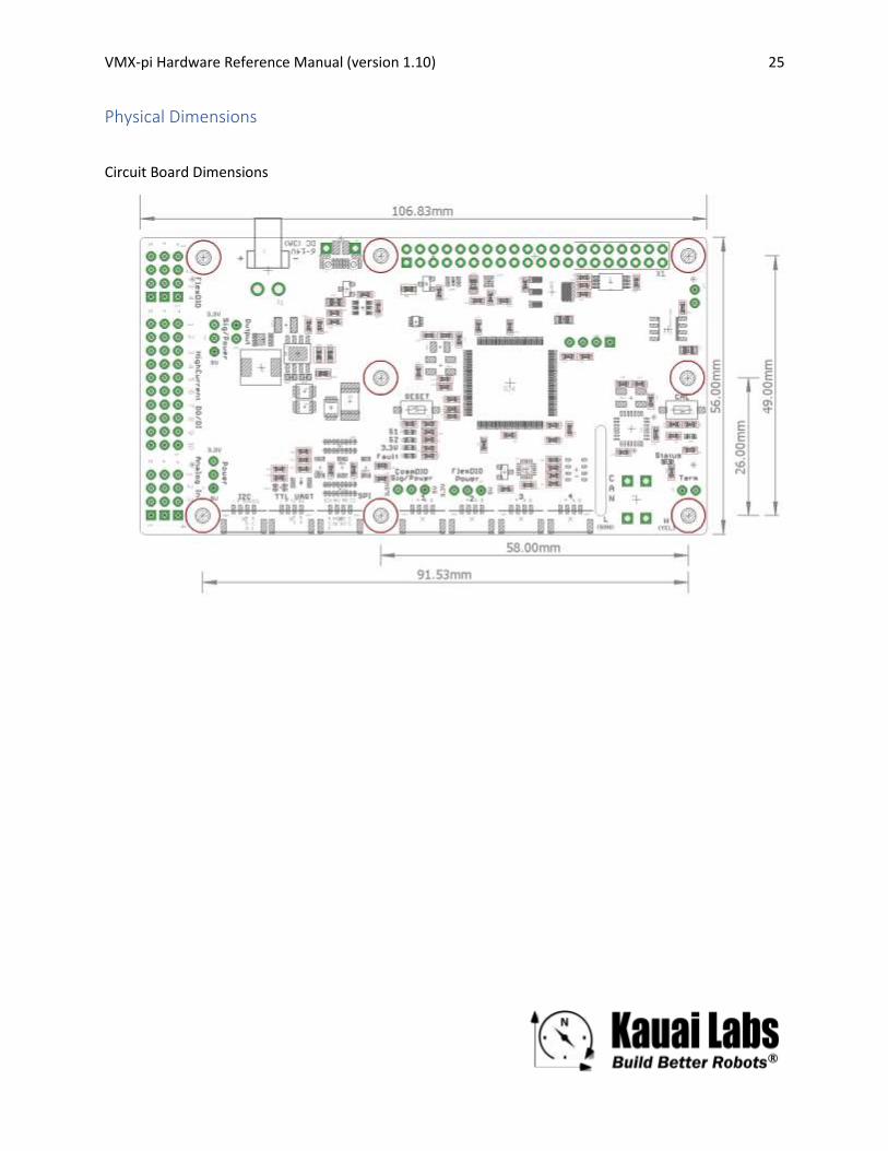
Physical Dimensions
Circuit Board Dimensions
Recommended
![Hardware Reference Manual - Kauai Labs...(or 1 DO, 1DI) HW Quadrature Decode (Max 5 Pair [10 pins]) PWM/Digital IOs (Max 12) 150mA Analog Supply Up to 400mA Digital Supply FlexDIO](https://img.pdfslide.net/doc/110x75/5fe9eaa4aa46cc099d312e00/hardware-reference-manual-kauai-labs-or-1-do-1di-hw-quadrature-decode-max.jpg)