YJ-BC-3030-G01 High CRI LED
Document Number: YJWJ008 www.yujiintl.com Rev Version 0.0, 25-3-2016 Approval by: ZHUAN, H.
This datasheet is subject to change without notice.
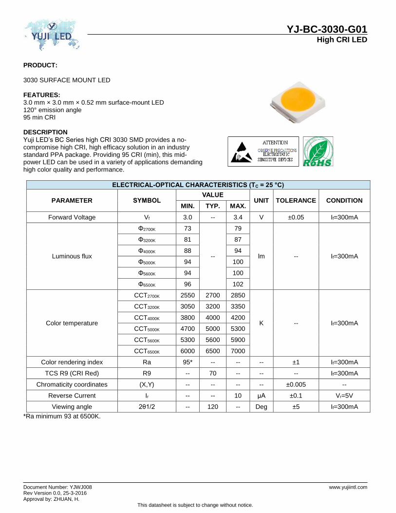
PRODUCT: 3030 SURFACE MOUNT LED FEATURES: 3.0 mm × 3.0 mm × 0.52 mm surface-mount LED 120° emission angle 95 min CRI DESCRIPTION Yuji LED’s BC Series high CRI 3030 SMD provides a no-compromise high CRI, high efficacy solution in an industry standard PPA package. Providing 95 CRI (min), this mid-power LED can be used in a variety of applications demanding high color quality and performance.
*Ra minimum 93 at 6500K.
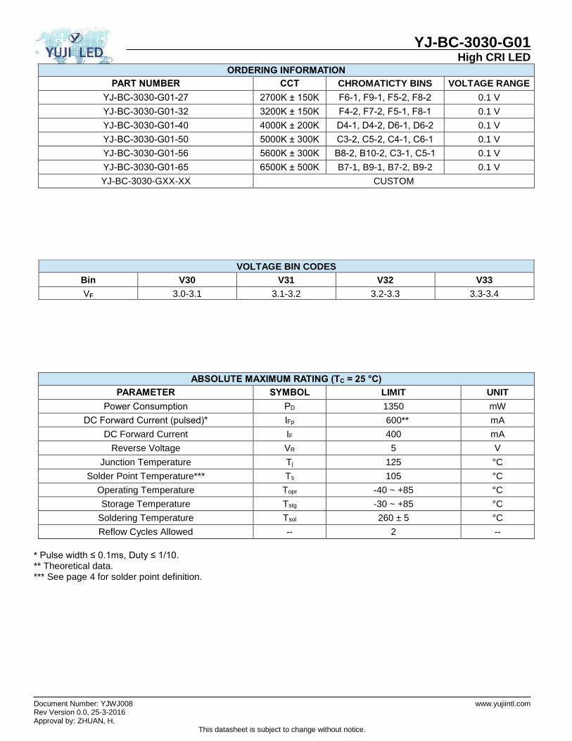
ELECTRICAL-OPTICAL CHARACTERISTICS (TC = 25 °C)
PARAMETER SYMBOL VALUE
UNIT TOLERANCE CONDITION MIN. TYP. MAX.
Forward Voltage Vf 3.0 -- 3.4 V ±0.05 If=300mA
Luminous flux
Φ2700K 73
--
79
lm -- If=300mA
Φ3200K 81 87
Φ4000K 88 94
Φ5000K 94 100
Φ5600K 94 100
Φ6500K 96 102
Color temperature
CCT2700K 2550 2700 2850
K -- If=300mA
CCT3200K 3050 3200 3350
CCT4000K 3800 4000 4200
CCT5000K 4700 5000 5300
CCT5600K 5300 5600 5900
CCT6500K 6000 6500 7000
Color rendering index Ra 95* -- -- -- ±1 If=300mA
TCS R9 (CRI Red) R9 -- 70 -- -- -- If=300mA
Chromaticity coordinates (X,Y) -- -- -- -- ±0.005 --
Reverse Current Ir -- -- 10 μA ±0.1 Vr=5V
Viewing angle 2θ1/2 -- 120 -- Deg ±5 If=300mA
YJ-BC-3030-G01 High CRI LED
Document Number: YJWJ008 www.yujiintl.com Rev Version 0.0, 25-3-2016 Approval by: ZHUAN, H.
This datasheet is subject to change without notice.
* Pulse width ≤ 0.1ms, Duty ≤ 1/10. ** Theoretical data. *** See page 4 for solder point definition.
ORDERING INFORMATION
PART NUMBER CCT CHROMATICTY BINS VOLTAGE RANGE
YJ-BC-3030-G01-27 2700K ± 150K F6-1, F9-1, F5-2, F8-2 0.1 V
YJ-BC-3030-G01-32 3200K ± 150K F4-2, F7-2, F5-1, F8-1 0.1 V
YJ-BC-3030-G01-40 4000K ± 200K D4-1, D4-2, D6-1, D6-2 0.1 V
YJ-BC-3030-G01-50 5000K ± 300K C3-2, C5-2, C4-1, C6-1 0.1 V
YJ-BC-3030-G01-56 5600K ± 300K B8-2, B10-2, C3-1, C5-1 0.1 V
YJ-BC-3030-G01-65 6500K ± 500K B7-1, B9-1, B7-2, B9-2 0.1 V
YJ-BC-3030-GXX-XX CUSTOM
VOLTAGE BIN CODES
Bin V30 V31 V32 V33
VF 3.0-3.1 3.1-3.2 3.2-3.3 3.3-3.4
ABSOLUTE MAXIMUM RATING (TC = 25 °C)
PARAMETER SYMBOL LIMIT UNIT
Power Consumption PD 1350 mW
DC Forward Current (pulsed)* IFp 600** mA
DC Forward Current IF 400 mA
Reverse Voltage VR 5 V
Junction Temperature Tj 125 °C
Solder Point Temperature*** Ts 105 °C
Operating Temperature Topr -40 ~ +85 °C
Storage Temperature Tstg -30 ~ +85 °C
Soldering Temperature Tsol 260 ± 5 °C
Reflow Cycles Allowed -- 2 --
YJ-BC-3030-G01 High CRI LED
Document Number: YJWJ008 www.yujiintl.com Rev Version 0.0, 25-3-2016 Approval by: ZHUAN, H.
This datasheet is subject to change without notice.
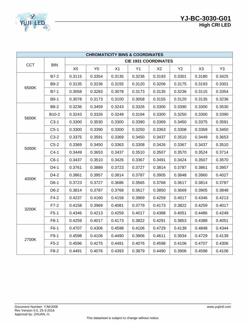
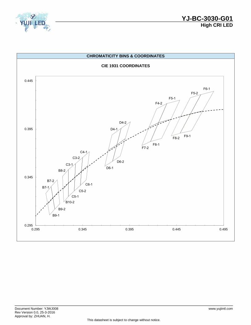
CHROMATICITY BINS & COORDINATES
CCT BIN CIE 1931 COORDINATES
X0 Y0 X1 Y1 X2 Y2 X3 Y3
6500K
B7-2 0.3115 0.3354 0.3135 0.3236 0.3193 0.3301 0.3180 0.3425
B9-2 0.3135 0.3236 0.3155 0.3120 0.3206 0.3175 0.3193 0.3301
B7-1 0.3058 0.3283 0.3078 0.3173 0.3135 0.3236 0.3115 0.3354
B9-1 0.3078 0.3173 0.3100 0.3058 0.3155 0.3120 0.3135 0.3236
5600K
B8-2 0.3236 0.3459 0.3243 0.3326 0.3300 0.3390 0.3300 0.3530
B10-2 0.3243 0.3326 0.3249 0.3194 0.3300 0.3250 0.3300 0.3390
C3-1 0.3300 0.3530 0.3300 0.3390 0.3369 0.3450 0.3375 0.3591
C5-1 0.3300 0.3390 0.3300 0.3250 0.3363 0.3308 0.3369 0.3450
5000K
C3-2 0.3375 0.3591 0.3369 0.3450 0.3437 0.3510 0.3449 0.3653
C5-2 0.3369 0.3450 0.3363 0.3308 0.3426 0.3367 0.3437 0.3510
C4-1 0.3449 0.3653 0.3437 0.3510 0.3507 0.3570 0.3524 0.3714
C6-1 0.3437 0.3510 0.3426 0.3367 0.3491 0.3424 0.3507 0.3570
4000K
D4-1 0.3761 0.3889 0.3723 0.3727 0.3814 0.3787 0.3861 0.3957
D4-2 0.3861 0.3957 0.3814 0.3787 0.3905 0.3848 0.3960 0.4027
D6-1 0.3723 0.3727 0.3686 0.3565 0.3768 0.3617 0.3814 0.3787
D6-2 0.3814 0.3787 0.3768 0.3617 0.3850 0.3669 0.3905 0.3848
3200K
F4-2 0.4237 0.4160 0.4158 0.3969 0.4259 0.4017 0.4346 0.4213
F7-2 0.4158 0.3969 0.4081 0.3779 0.4173 0.3822 0.4259 0.4017
F5-1 0.4346 0.4213 0.4259 0.4017 0.4388 0.4051 0.4486 0.4249
F8-1 0.4259 0.4017 0.4173 0.3822 0.4291 0.3853 0.4388 0.4051
2700K
F6-1 0.4707 0.4306 0.4598 0.4106 0.4729 0.4139 0.4848 0.4344
F9-1 0.4598 0.4106 0.4490 0.3906 0.4611 0.3934 0.4729 0.4139
F5-2 0.4596 0.4275 0.4491 0.4076 0.4598 0.4106 0.4707 0.4306
F8-2 0.4491 0.4076 0.4393 0.3879 0.4490 0.3906 0.4598 0.4106
YJ-BC-3030-G01 High CRI LED
Document Number: YJWJ008 www.yujiintl.com Rev Version 0.0, 25-3-2016 Approval by: ZHUAN, H.
This datasheet is subject to change without notice.
CHROMATICITY BINS & COORDINATES
CIE 1931 COORDINATES
0.295
0.345
0.395
0.445
0.295 0.345 0.395 0.445 0.495
B8-2
C3-1
B10-2
C5-1
F4-2
F5-1
F7-2F8-1
F5-2
F8-2
F6-1
F9-1
B7-1
B7-2
B9-1
B9-2
D4-1
D4-2
D6-1
D6-2C3-2
C4-1
C5-2
C6-1
YJ-BC-3030-G01 High CRI LED
Document Number: YJWJ008 www.yujiintl.com Rev Version 0.0, 25-3-2016 Approval by: ZHUAN, H.
This datasheet is subject to change without notice.
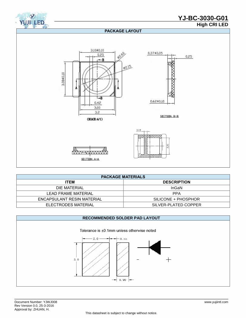
PACKAGE LAYOUT
PACKAGE MATERIALS
ITEM DESCRIPTION
DIE MATERIAL InGaN
LEAD FRAME MATERIAL PPA
ENCAPSULANT RESIN MATERIAL SILICONE + PHOSPHOR
ELECTRODES MATERIAL SILVER-PLATED COPPER
RECOMMENDED SOLDER PAD LAYOUT

YJ-BC-3030-G01 High CRI LED
Document Number: YJWJ008 www.yujiintl.com Rev Version 0.0, 25-3-2016 Approval by: ZHUAN, H.
This datasheet is subject to change without notice.
CHARACTERISTIC CURVES ALL CHARACTERISTIC CURVES ARE FOR REFERENCE ONLY AND NOT GUARANTEED
FORWARD CURRENT
VS FORWARD VOLTAGE (TA=25°C)
FORWARD CURRENT
VS RELATIVE LUMINOUS OUTPUT (TA=25°C)
SOLDER POINT TEMPERATURE VS FORWARD VOLTAGE ( IF = 300 mA)
SOLDER POINT TEMPERATURE
VS RELATIVE LUMINOUS OUTPUT ( IF = 300 mA)
FORWARD CURRENT VS CHROMATICITY SHIFT (4000K,TA=25°C)
FORWARD CURRENT VS CHROMATICITY SHIFT
(4000K,TA=25°C)
0
50
100
150
200
250
300
350
400
450
2.5 2.7 2.9 3.1 3.3 3.5
Fo
rward
Curr
ent
(mA
)
Forward Voltage (V)
0.0
0.2
0.4
0.6
0.8
1.0
1.2
1.4
0 100 200 300 400
Rela
tive L
um
inous O
utp
ut
Forward Current (mA)
-0.20
-0.15
-0.10
-0.05
0.00
0.05
25 45 65 85 105
Fo
rward
Voltage C
hange (
V)
Ts [°C]
0.0
0.2
0.4
0.6
0.8
1.0
1.2
25 45 65 85 105
Rela
tive L
um
inous O
utp
ut
Ts [°C]
-0.015
-0.010
-0.005
0.000
0.005
0 100 200 300 400
Chro
maticity S
hift (C
IE 1
931)
Forward Current (mA)
CIE Y
CIE X
100 mA
200 mA
300 mA400 mA
0.3690
0.3700
0.3710
0.3720
0.3730
0.3740
0.3750
0.3760
0.3770
0.379 0.381 0.383 0.385
CIE
Y
CIE X
YJ-BC-3030-G01 High CRI LED
Document Number: YJWJ008 www.yujiintl.com Rev Version 0.0, 25-3-2016 Approval by: ZHUAN, H.
This datasheet is subject to change without notice.
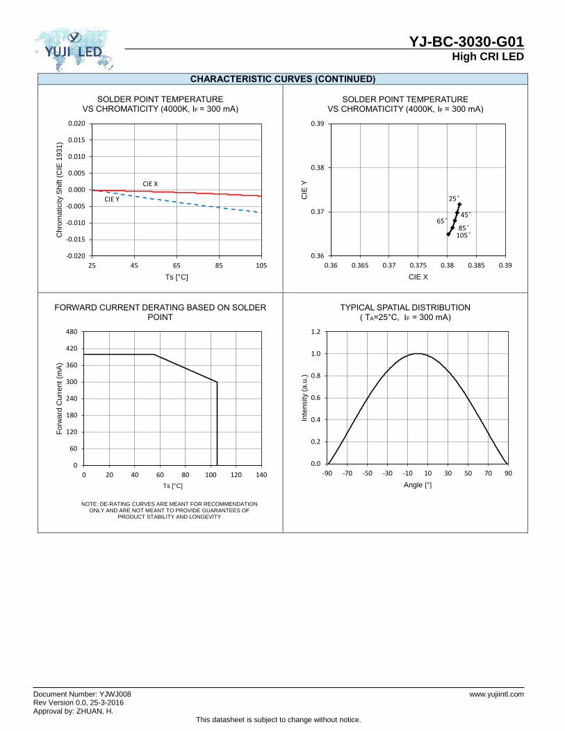
CHARACTERISTIC CURVES (CONTINUED)
SOLDER POINT TEMPERATURE
VS CHROMATICITY (4000K, IF = 300 mA)
SOLDER POINT TEMPERATURE
VS CHROMATICITY (4000K, IF = 300 mA)
FORWARD CURRENT DERATING BASED ON SOLDER POINT
NOTE: DE-RATING CURVES ARE MEANT FOR RECOMMENDATION
ONLY AND ARE NOT MEANT TO PROVIDE GUARANTEES OF PRODUCT STABILITY AND LONGEVITY
TYPICAL SPATIAL DISTRIBUTION
( TA=25°C, IF = 300 mA)
-0.020
-0.015
-0.010
-0.005
0.000
0.005
0.010
0.015
0.020
25 45 65 85 105
Chro
maticity S
hift (C
IE 1
931)
Ts [°C]
CIE X
CIE Y 25°
45°65°
85°105°
0.36
0.37
0.38
0.39
0.36 0.365 0.37 0.375 0.38 0.385 0.39
CIE
Y
CIE X
0
60
120
180
240
300
360
420
480
0 20 40 60 80 100 120 140
Fo
rward
Curr
ent
(mA
)
Ts [°C]
0.0
0.2
0.4
0.6
0.8
1.0
1.2
-90 -70 -50 -30 -10 10 30 50 70 90
Inte
nsity (
a.u
.)
Angle [°]
YJ-BC-3030-G01 High CRI LED
Document Number: YJWJ008 www.yujiintl.com Rev Version 0.0, 25-3-2016 Approval by: ZHUAN, H.
This datasheet is subject to change without notice.
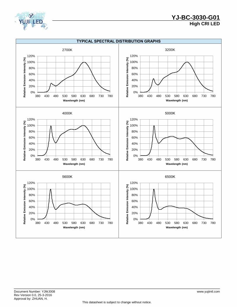
TYPICAL SPECTRAL DISTRIBUTION GRAPHS
2700K
3200K
4000K
5000K
5600K
6500K
0%
20%
40%
60%
80%
100%
120%
380 430 480 530 580 630 680 730 780Rela
tive E
mis
sio
n I
nte
nsit
y (
%)
Wavelength (nm)
0%
20%
40%
60%
80%
100%
120%
380 430 480 530 580 630 680 730 780Rela
tive E
mis
sio
n I
nte
nsit
y (
%)
Wavelength (nm)
0%
20%
40%
60%
80%
100%
120%
380 430 480 530 580 630 680 730 780Rela
tive E
mis
sio
n I
nte
nsit
y (
%)
Wavelength (nm)
0%
20%
40%
60%
80%
100%
120%
380 430 480 530 580 630 680 730 780Rela
tive E
mis
sio
n I
nte
nsit
y (
%)
Wavelength (nm)
0%
20%
40%
60%
80%
100%
120%
380 430 480 530 580 630 680 730 780Rela
tive E
mis
sio
n I
nte
nsit
y (
%)
Wavelength (nm)
0%
20%
40%
60%
80%
100%
120%
380 430 480 530 580 630 680 730 780Rela
tive E
mis
sio
n I
nte
nsit
y (
%)
Wavelength (nm)
YJ-BC-3030-G01 High CRI LED
Document Number: YJWJ008 www.yujiintl.com Rev Version 0.0, 25-3-2016 Approval by: ZHUAN, H.
This datasheet is subject to change without notice.
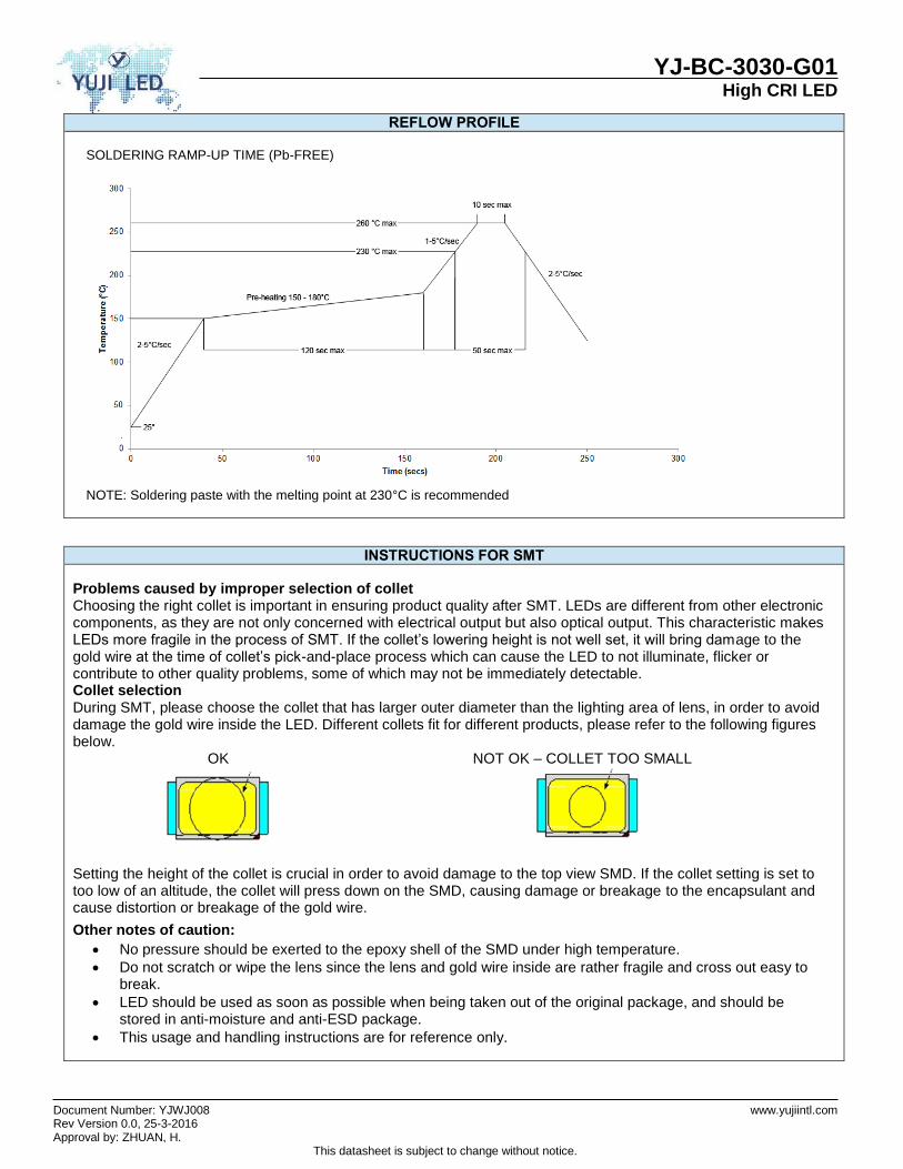
REFLOW PROFILE
SOLDERING RAMP-UP TIME (Pb-FREE)
NOTE: Soldering paste with the melting point at 230°C is recommended
INSTRUCTIONS FOR SMT
Problems caused by improper selection of collet Choosing the right collet is important in ensuring product quality after SMT. LEDs are different from other electronic components, as they are not only concerned with electrical output but also optical output. This characteristic makes LEDs more fragile in the process of SMT. If the collet’s lowering height is not well set, it will bring damage to the gold wire at the time of collet’s pick-and-place process which can cause the LED to not illuminate, flicker or contribute to other quality problems, some of which may not be immediately detectable. Collet selection During SMT, please choose the collet that has larger outer diameter than the lighting area of lens, in order to avoid damage the gold wire inside the LED. Different collets fit for different products, please refer to the following figures below.
OK NOT OK – COLLET TOO SMALL
Setting the height of the collet is crucial in order to avoid damage to the top view SMD. If the collet setting is set to too low of an altitude, the collet will press down on the SMD, causing damage or breakage to the encapsulant and cause distortion or breakage of the gold wire.
Other notes of caution:
No pressure should be exerted to the epoxy shell of the SMD under high temperature.
Do not scratch or wipe the lens since the lens and gold wire inside are rather fragile and cross out easy to break.
LED should be used as soon as possible when being taken out of the original package, and should be stored in anti-moisture and anti-ESD package.
This usage and handling instructions are for reference only.
YJ-BC-3030-G01 High CRI LED
Document Number: YJWJ008 www.yujiintl.com Rev Version 0.0, 25-3-2016 Approval by: ZHUAN, H.
This datasheet is subject to change without notice.
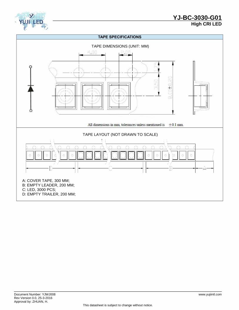
TAPE SPECIFICATIONS
TAPE DIMENSIONS (UNIT: MM)
TAPE LAYOUT (NOT DRAWN TO SCALE)
A: COVER TAPE, 300 MM; B: EMPTY LEADER, 200 MM; C: LED, 3000 PCS; D: EMPTY TRAILER, 200 MM;

YJ-BC-3030-G01 High CRI LED
Document Number: YJWJ008 www.yujiintl.com Rev Version 0.0, 25-3-2016 Approval by: ZHUAN, H.
This datasheet is subject to change without notice.
REEL SPECIFICATIONS
REEL DIMENSIONS TOP (UNIT: MM)
REEL DIMENSIONS BOTTOM (UNIT: MM)
REEL DIMENSIONS SIDE (UNIT: MM)
FEEDING DIRECTION
LOT NUMBERING SCHEME Yuji LED uses two formats for lot numbering purposes: 1) YYYY-MM-XXX-Z YYYY: 4-digit manufacturing year MM: 2-digit manufacturing month XXX: 3-digit inventory number (000 – 999) Z: internal alphanumeric code 2) YYYYMMXXX YYYY: 4-digit manufacturing year MM: 2-digit manufacturing month XXX: 3-digit inventory number (000 – 999)
YJ-BC-3030-G01 High CRI LED
Document Number: YJWJ008 www.yujiintl.com Rev Version 0.0, 25-3-2016 Approval by: ZHUAN, H.
This datasheet is subject to change without notice.
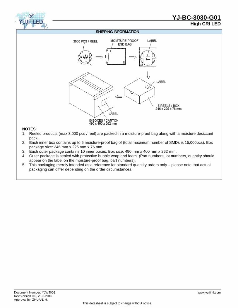
SHIPPING INFORMATION
NOTES: 1. Reeled products (max 3,000 pcs / reel) are packed in a moisture-proof bag along with a moisture desiccant
pack. 2. Each inner box contains up to 5 moisture-proof bag of (total maximum number of SMDs is 15,000pcs). Box
package size: 246 mm x 225 mm x 76 mm. 3. Each outer package contains 10 inner boxes. Box size: 490 mm x 400 mm x 262 mm. 4. Outer package is sealed with protective bubble wrap and foam. (Part numbers, lot numbers, quantity should
appear on the label on the moisture-proof bag, part numbers). 5. This packaging merely intended as a reference for standard quantity orders only – please note that actual
packaging can differ depending on the order circumstances.
Recommended