Michael Specht
Centre for Solar Energy and Hydrogen Research (ZSW), Stuttgart
In Kooperation
mit:Fraunhofer
Institute for Wind Energy and Energy System Technology (IWES), Kassel
SolarFuel
GmbH, Stuttgart
Impulsvortrag:Aktueller Stand der Power-to-Gas – Technologie
Power-to-GasErdgasinfrastruktur als EnergiespeicherBundesnetzagentur / Fraunhofer IWES22.11.2011, Auditorium Friedrichstraße, Berlin
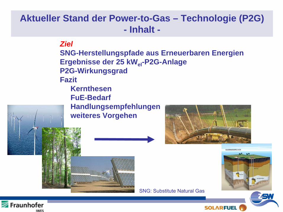
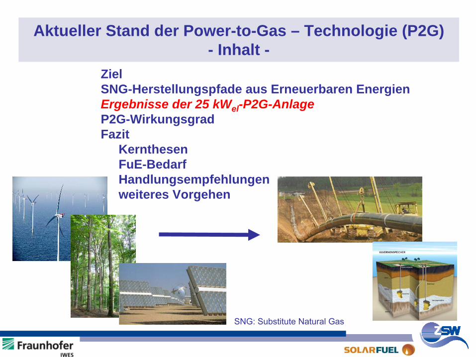
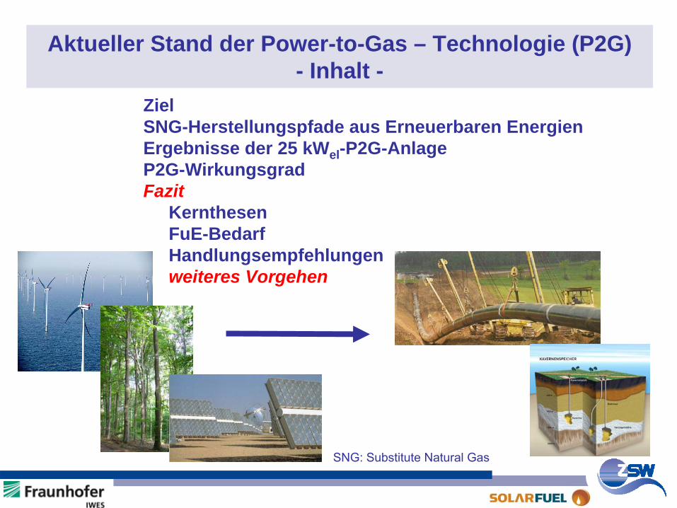
Aktueller Stand der Power-to-Gas – Technologie (P2G) - Inhalt -
ZielSNG-Herstellungspfade aus Erneuerbaren EnergienErgebnisse der 25 kWel -P2G-AnlageP2G-WirkungsgradFazit
KernthesenFuE-BedarfHandlungsempfehlungenweiteres Vorgehen
SNG: Substitute
Natural
Gas
Long Term Storage of Renewable Energy (RE) - FAQ -
How is long-term storage of energy realised today?
How much capacity do we need for RE storage?
What is the best way to collect and to store RE?
Can the existing infrastructure be used to store and to distribute RE?
What is “the” future fuel for mobility?
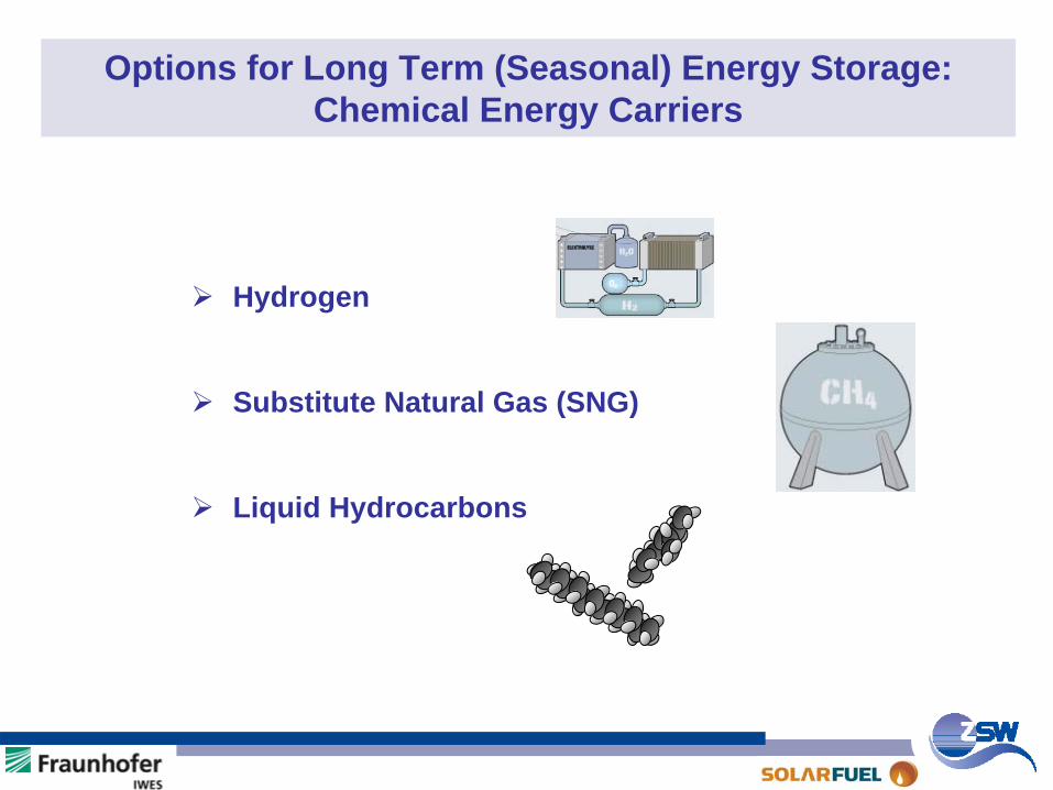
Options for Long Term (Seasonal) Energy Storage: Chemical Energy Carriers
Hydrogen
Substitute Natural Gas (SNG)
Liquid Hydrocarbons
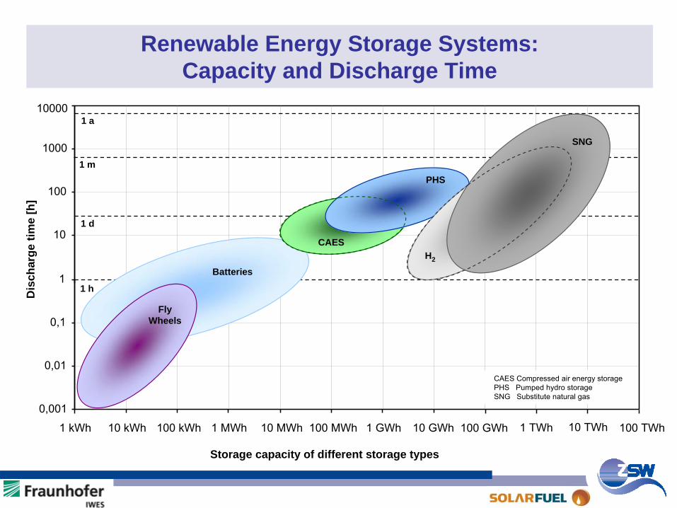
Renewable Energy Storage Systems: Capacity and Discharge Time
0,001
0,01
0,1
1
10
100
1000
10000
1 kWh 10 kWh 100 kWh 1 MWh 10 MWh 100 MWh 1 GWh 10 GWh 100 GWh
1 m
1 h
1 d
CAES
1 TWh 10 TWh 100 TWh
CAES
Fly Wheels
Storage capacity of different storage types
Dis
char
ge ti
me
[h]
CAES Compressed
air
energy
storage
PHS Pumped
hydro
storage
SNG Substitute
natural
gas
Batteries
PHS
1 a
SNG
H2

Aktueller Stand der Power-to-Gas – Technologie (P2G) - Inhalt -
Ziel SNG-Herstellungspfade aus Erneuerbaren EnergienErgebnisse der 25 kWel -P2G-AnlageP2G-WirkungsgradFazit
KernthesenFuE-BedarfHandlungsempfehlungenweiteres Vorgehen
SNG: Substitute
Natural
Gas
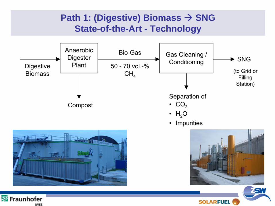
Path 1: (Digestive) Biomass SNG State-of-the-Art - Technology
AnaerobicDigester
Plant
Gas Cleaning /Conditioning
Bio-Gas
50 - 70 vol.-%CH4
DigestiveBiomass
Compost
SNG
Separation of• CO2
• H2O• Impurities
(to Grid orFilling
Station)
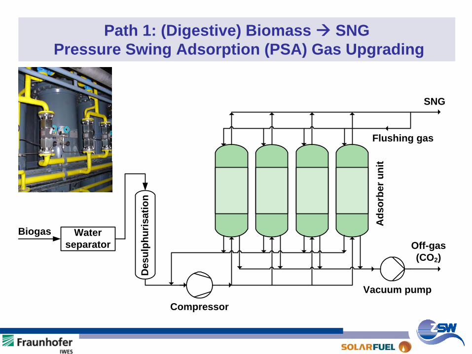
Path 1: (Digestive) Biomass SNGPressure Swing Adsorption (PSA) Gas Upgrading
Biogas
Vacuum pump
Off-gas(CO2)
Flushing gas
SNG
Water separator
Compressor
Des
ulph
uris
atio
n
Ads
orbe
r uni
t
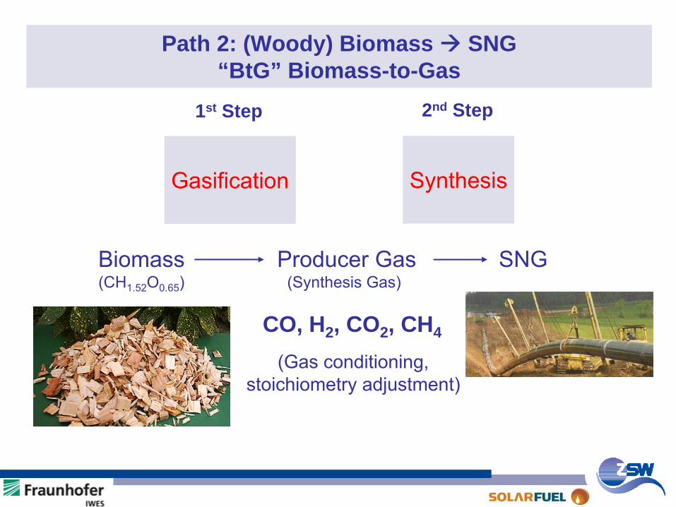
Path 2: (Woody) Biomass SNG“BtG” Biomass-to-Gas
CO, H2 , CO2 , CH4
Gasification
Biomass
Producer Gas
SNG(CH1.52
O0.65
)
(Synthesis Gas)
(Gas conditioning,stoichiometry
adjustment)
1st Step 2nd Step
Synthesis
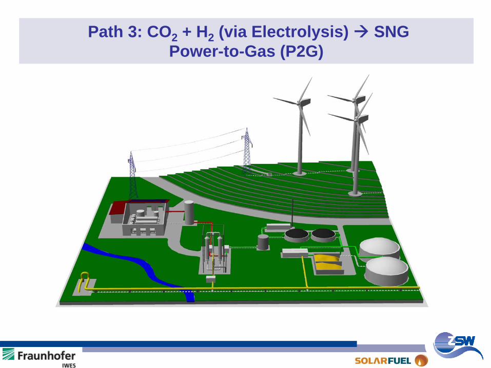
Path 3: CO2 + H2 (via Electrolysis) SNGPower-to-Gas (P2G)
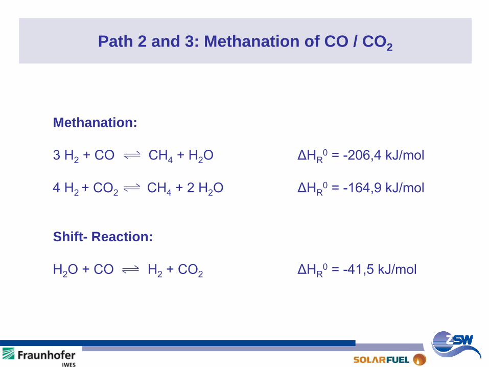
Path 2 and 3: Methanation of CO / CO2
Methanation:
3 H2
+ CO CH4
+ H2
O ΔHR0
= -206,4 kJ/mol
4 H2 + CO2 CH4
+ 2 H2
O ΔHR0
= -164,9 kJ/mol
Shift- Reaction:
H2
O + CO H2
+ CO2
ΔHR0
= -41,5 kJ/mol
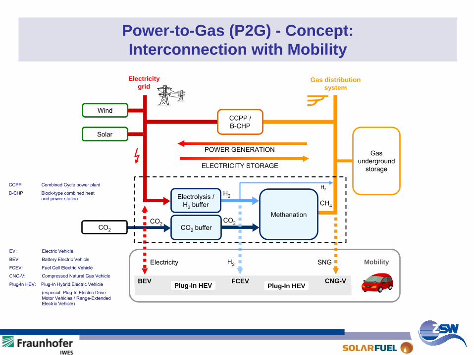
Power-to-Gas (P2G) - Concept: Interconnection with Mobility
EV:
Electric Vehicle
BEV: Battery Electric Vehicle
FCEV: Fuel Cell Electric Vehicle
CNG-V: Compressed Natural Gas Vehicle
Plug-In HEV: Plug-In Hybrid Electric Vehicle
(especial: Plug-In Electric Drive Motor Vehicles / Range-Extended Electric Vehicle)
CCPP Combined
Cycle
power plant
B-CHP Block-type combined heat and power station
Solar
WindCCPP / B-CHP
CO2
buffer
Electricitygrid
Gas distribution system
Electrolysis
/
H2
bufferMethanation
H2
CO2
CH4
POWER GENERATION
ELECTRICITY STORAGE
CO2
Gas
underground
storage
Electricity H2 SNG
BEV FCEV CNG-V
Mobility
H2
CO2
Plug-In HEV Plug-In HEV
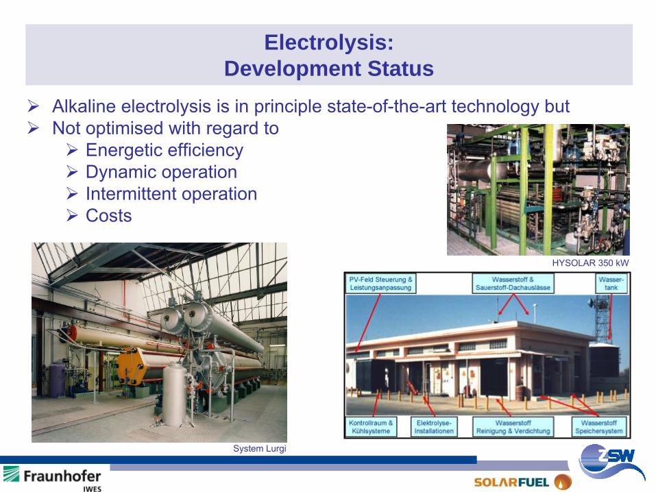
Electrolysis: Development Status
Alkaline electrolysis is in principle state-of-the-art technology butNot optimised with regard to
Energetic efficiencyDynamic operationIntermittent operationCosts
System Lurgi
HYSOLAR 350 kW
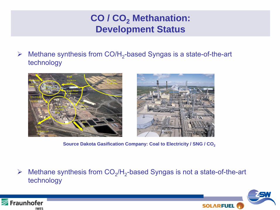
CO / CO2 Methanation: Development Status
Methane synthesis from CO/H2-based Syngas is a state-of-the-art technology
Methane synthesis from CO2/H2-based Syngas is not a state-of-the-art technology
Source Dakota Gasification Company: Coal to Electricity / SNG / CO2
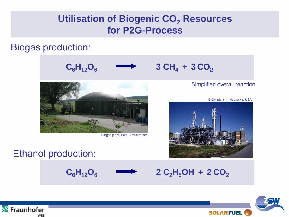
Utilisation of Biogenic CO2 Resources for P2G-Process
C6 H12 O6 3 CH4 + 3 CO2
Simplified overall reaction
C6 H12 O6 2 C2 H5OH + 2 CO2
Biogas production:
Ethanol production:
Biogas plant, Foto: Krautkremer
EtOH
plant in Nebraska, USA
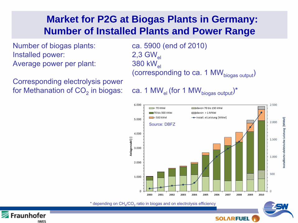
Market for P2G at Biogas Plants in Germany: Number of Installed Plants and Power Range
Source: DBFZ
Number of biogas plants:
ca. 5900 (end of 2010)Installed power: 2,3 GWelAverage power per plant: 380 kWel
(corresponding to ca. 1 MWbiogas
output
)Corresponding electrolysis power for Methanation
of CO2
in biogas: ca. 1 MWel
(for 1 MWbiogas
output
)*
* depending
on CH4
/CO2
ratio
in biogas
and on electrolysis
efficiency
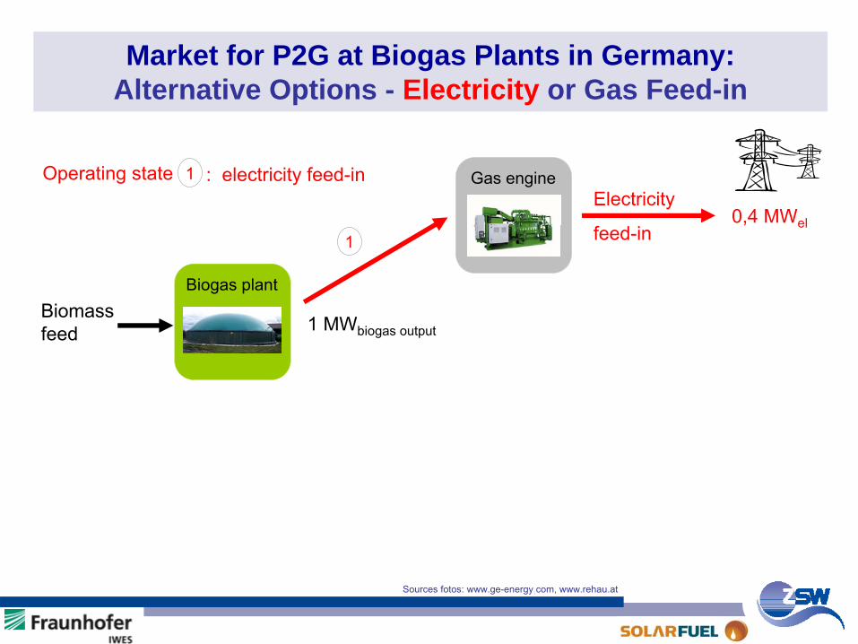
Market for P2G at Biogas Plants in Germany: Alternative Options - Electricity or Gas Feed-in
Biomass
feed
Electricity
feed-in0,4 MWel
Biogas plant
Gas engine
1
1 MWbiogas
output
Operating state 1 : electricity feed-in
Sources fotos: www.ge-energy.com, www.rehau.at
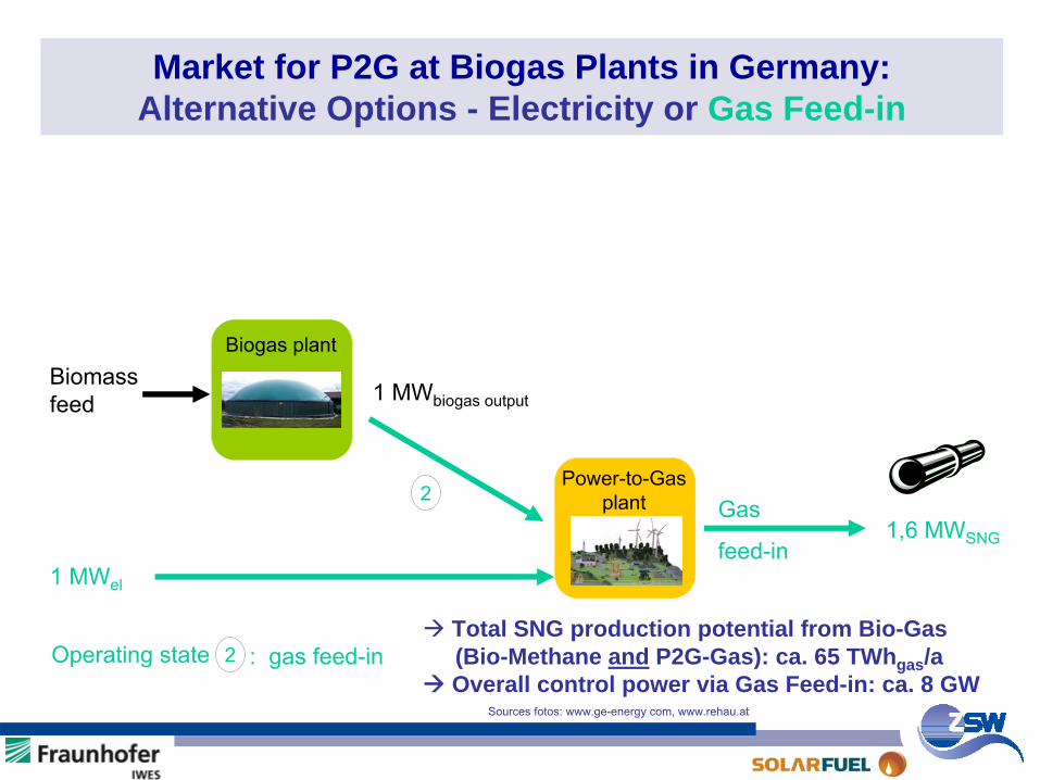
Market for P2G at Biogas Plants in Germany: Alternative Options - Electricity or Gas Feed-in
Biomass
feed
Gas
feed-in1,6 MWSNG
Biogas plant
Power-to-Gas plant
1 MWel
2
Operating state 2 : gas feed-in
1 MWbiogas
output
Sources fotos: www.ge-energy.com, www.rehau.at
Total SNG production potential from Bio-Gas (Bio-Methane and P2G-Gas): ca. 65 TWhgas /aOverall control power via Gas Feed-in: ca. 8 GW
Aktueller Stand der Power-to-Gas – Technologie (P2G) - Inhalt -
Ziel SNG-Herstellungspfade aus Erneuerbaren EnergienErgebnisse der 25 kWel -P2G-AnlageP2G-WirkungsgradFazit
KernthesenFuE-BedarfHandlungsempfehlungenweiteres Vorgehen
SNG: Substitute
Natural
Gas
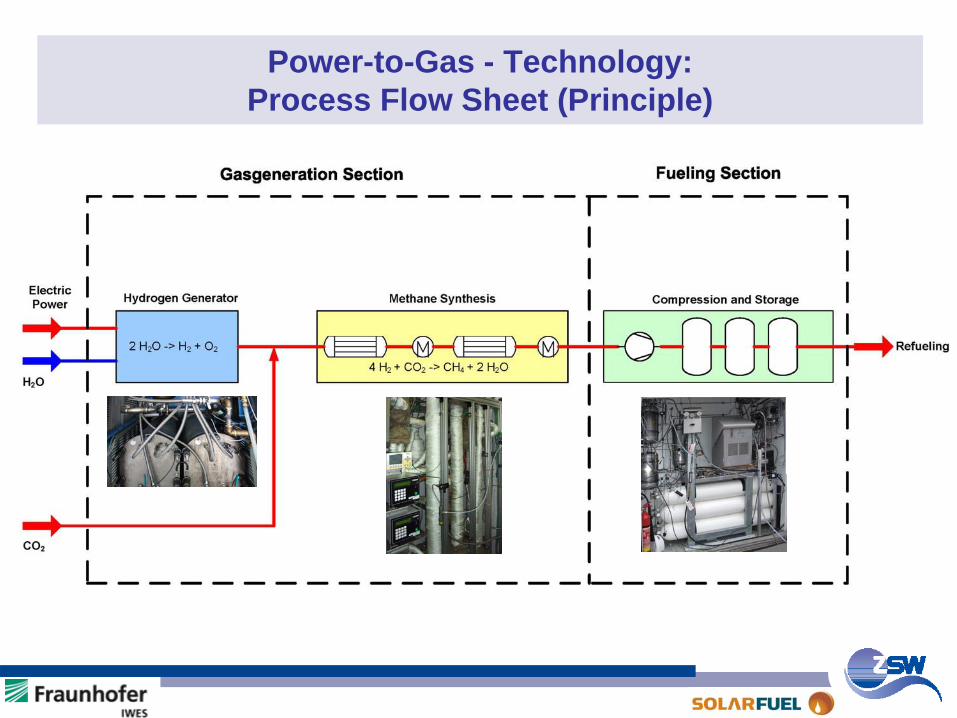
Power-to-Gas - Technology: Process Flow Sheet (Principle)
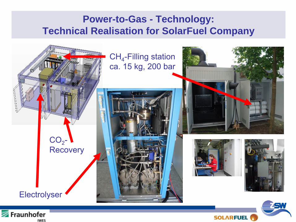
Power-to-Gas - Technology: Technical Realisation for SolarFuel Company
CH4
-Filling stationca. 15 kg, 200 bar
Electrolyser
CO2
-Recovery
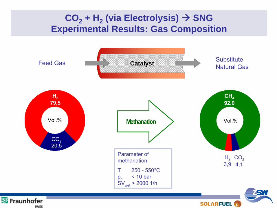
CO2 + H2 (via Electrolysis) SNGExperimental Results: Gas Composition
Parameter of methanation:
T 250 -
550°C
pe
< 10 bar
SVwet
> 2000 1/h
Catalyst Substitute
Natural Gas Feed
Gas
Vol.%
H2 79,5
CO2
20,5
Methanation
H2
3,9
CO2
4,1
CH4 92,0
Vol.%
80
85
90
95
100
13400 17000 20600 24200 27800 31400 35000Test Duration [h]
CH
4-C
onte
nt [v
ol-%
]
0
5
10
15
20
CO
2-, H
2-C
onte
nt [v
ol-%
]
CH4CO2H2
0 1 2 3 4 5 6
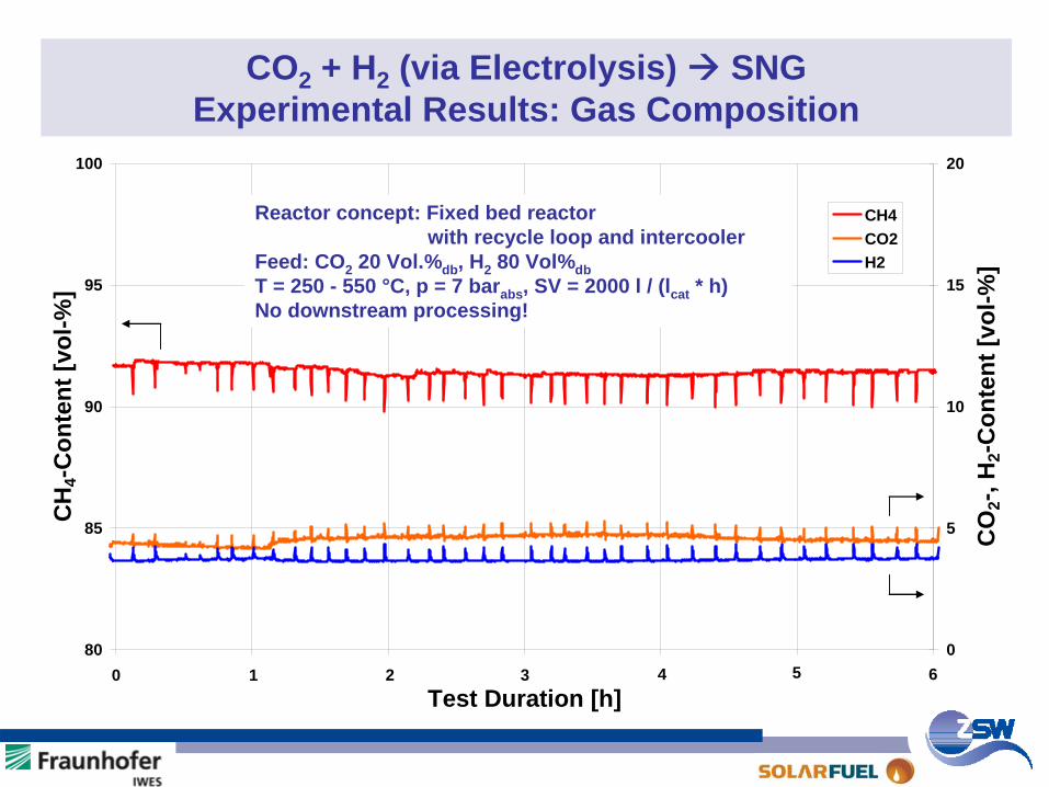
CO2 + H2 (via Electrolysis) SNG Experimental Results: Gas Composition
Reactor concept: Fixed bed reactor with recycle loop and intercooler
Feed: CO2 20 Vol.%db , H2 80 Vol%dbT = 250 - 550 °C, p = 7 barabs , SV = 2000 l / (lcat * h)No downstream processing!
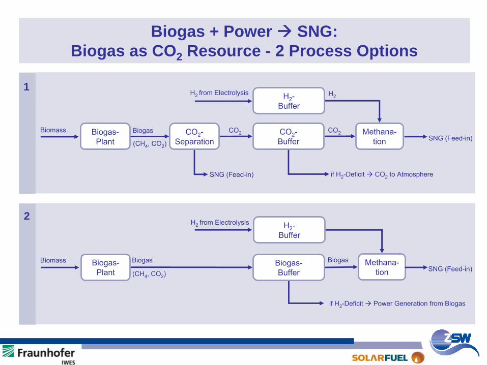
Biogas + Power SNG:Biogas as CO2 Resource - 2 Process Options
Biogas-
Plant
CO2
-
Separation
CO2
-
Buffer
Methana-
tion
H2
-
Buffer
H2
-
Buffer
Biogas-
Buffer
Methana-
tion
Biogas-
Plant
Biomass
Biomass
Biogas
Biogas
(CH4
, CO2
)
(CH4
, CO2
)
CO2 CO2
H2 from Electrolysis H2
SNG (Feed-in)
if H2
-Deficit CO2 to AtmosphereSNG (Feed-in)
H2 from Electrolysis
BiogasSNG (Feed-in)
if H2
-Deficit Power Generation from Biogas
1
2
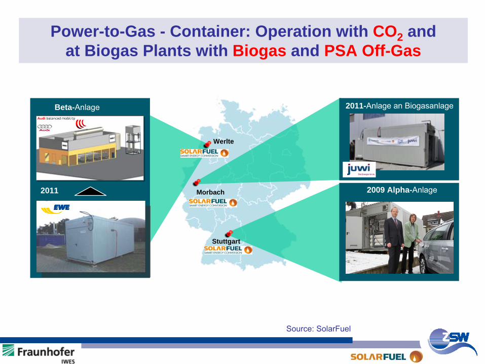
Power-to-Gas - Container: Operation with CO2 and at Biogas Plants with Biogas and PSA Off-Gas
Werlte
Stuttgart
2009 Alpha-Anlage
2011-Anlage an Biogasanlage
Morbach
Beta-Anlage
Source:
SolarFuel
2011
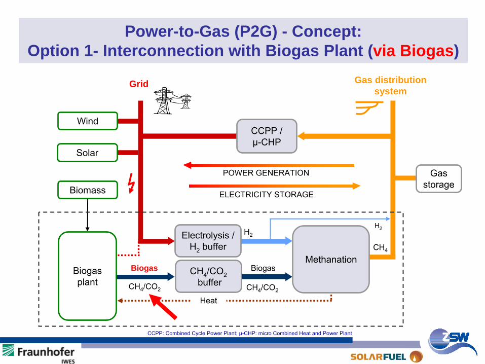
Power-to-Gas (P2G) - Concept: Option 1- Interconnection with Biogas Plant (via Biogas)
CCPP / µ-CHP
CH4
/CO2
buffer
Grid Gas distribution system
Electrolysis /
H2
bufferH2
Biogas
CH4
POWER GENERATION
ELECTRICITY STORAGE
Biogas
Gas
storageBiomass
Solar
Wind
H2
Biogas
plant
Methanation
HeatCH4
/CO2CH4
/CO2
CCPP: Combined Cycle Power Plant; µ-CHP: micro Combined Heat and Power Plant
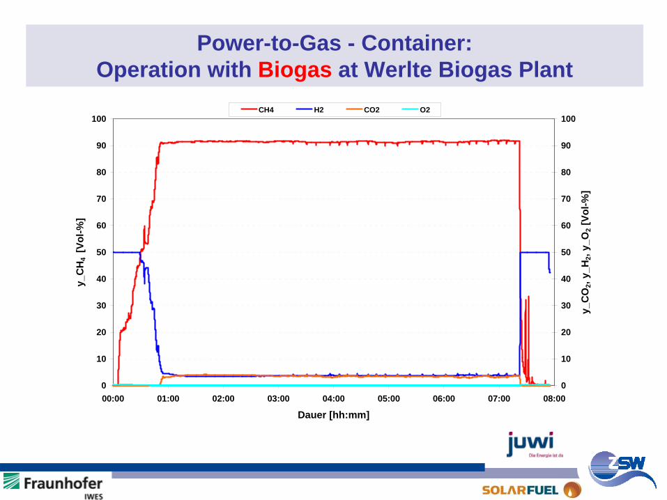
Power-to-Gas - Container: Operation with Biogas at Werlte Biogas Plant
0
10
20
30
40
50
60
70
80
90
100
00:00 01:00 02:00 03:00 04:00 05:00 06:00 07:00 08:00
Dauer [hh:mm]
y_C
H4
[Vol
-%]
0
10
20
30
40
50
60
70
80
90
100
y_C
O2,
y_H
2, y_
O2 [
Vol-%
]
CH4 H2 CO2 O2
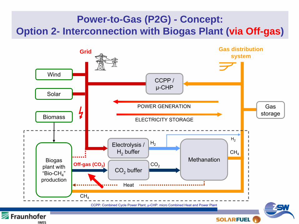
Power-to-Gas (P2G) - Concept: Option 2- Interconnection with Biogas Plant (via Off-gas)
CCPP / µ-CHP
CO2
buffer
Grid Gas distribution system
Electrolysis /
H2
bufferH2
CO2
CH4
POWER GENERATION
ELECTRICITY STORAGE
Off-gas (CO2 )
Gas
storageBiomass
Solar
Wind
H2
Biogas plant with “Bio-CH4
”
production
CH4
Methanation
Heat
CCPP: Combined Cycle Power Plant; µ-CHP: micro Combined Heat and Power Plant
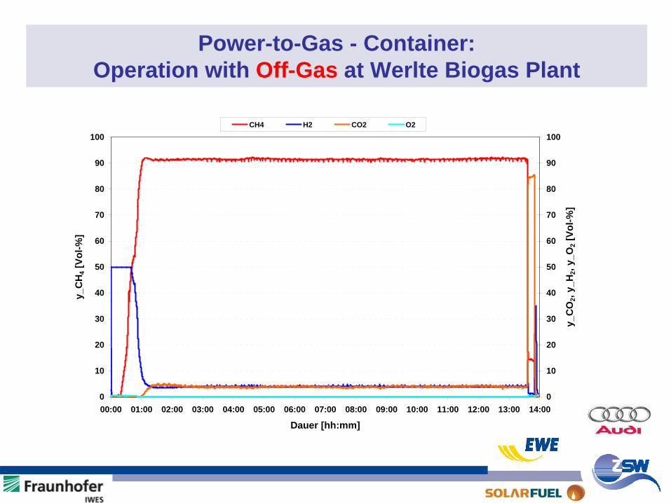
Power-to-Gas - Container: Operation with Off-Gas at Werlte Biogas Plant
0
10
20
30
40
50
60
70
80
90
100
00:00 01:00 02:00 03:00 04:00 05:00 06:00 07:00 08:00 09:00 10:00 11:00 12:00 13:00 14:00
Dauer [hh:mm]
y_C
H4 [
Vol-%
]
0
10
20
30
40
50
60
70
80
90
100
y_C
O2,
y_H
2, y_
O2 [
Vol-%
]
CH4 H2 CO2 O2

Aktueller Stand der Power-to-Gas – Technologie (P2G) - Inhalt -
Ziel SNG-Herstellungspfade aus Erneuerbaren EnergienErgebnisse der 25 kWel -P2G-AnlageP2G-WirkungsgradFazit
KernthesenFuE-BedarfHandlungsempfehlungenweiteres Vorgehen
SNG: Substitute
Natural
Gas
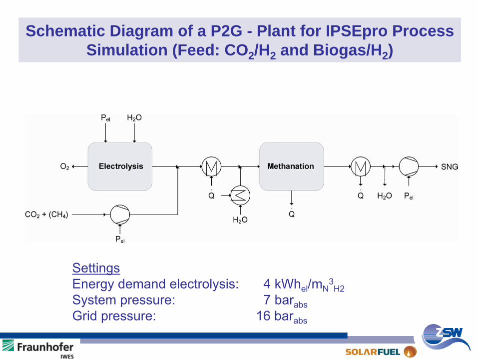
Schematic Diagram of a P2G - Plant for IPSEpro Process Simulation (Feed: CO2 /H2 and Biogas/H2 )
SettingsEnergy demand electrolysis:
4 kWhel
/mN3H2
System pressure:
7 barabsGrid pressure:
16 barabs
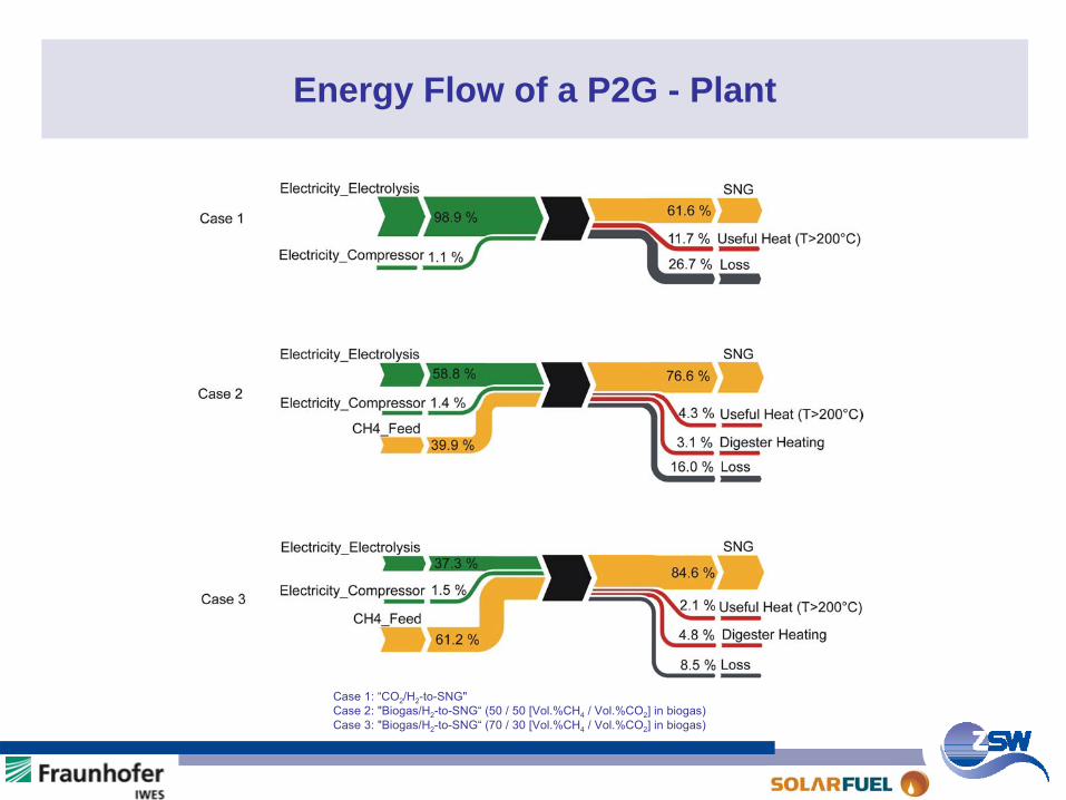
Energy Flow of a P2G - Plant
Case
1: “CO2
/H2
-to-SNG"Case
2: "Biogas/H2
-to-SNG“
(50 / 50 [Vol.%CH4
/ Vol.%CO2
] in biogas)Case
3: "Biogas/H2
-to-SNG“
(70 / 30 [Vol.%CH4
/ Vol.%CO2
] in biogas)
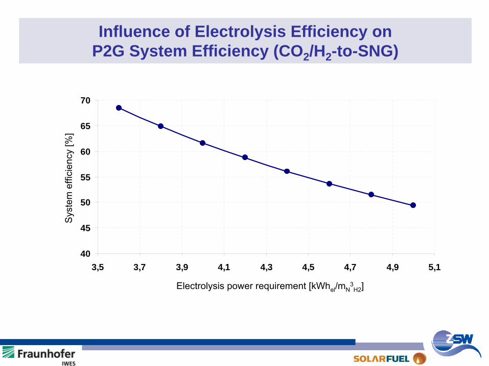
Influence of Electrolysis Efficiency on P2G System Efficiency (CO2 /H2 -to-SNG)
40
45
50
55
60
65
70
3,5 3,7 3,9 4,1 4,3 4,5 4,7 4,9 5,1
Electrolysis power requirement [kWhel
/mN3H2
]
Sys
tem
effi
cien
cy [%
]

Aktueller Stand der Power-to-Gas – Technologie (P2G) - Inhalt -
Ziel SNG-Herstellungspfade aus Erneuerbaren EnergienErgebnisse der 25 kWel -P2G-AnlageP2G-WirkungsgradFazit
KernthesenFuE-BedarfHandlungsempfehlungenweiteres Vorgehen
SNG: Substitute
Natural
Gas
Power-to-Gas (P2G) Fazit - Kernthesen (1)
Status:
Die Bevorratung (Speicherung) von Energie wird heute durch dieLagerung fossiler, C-basierter Brennstoffe gelöst (Kohle, Erdöl, Erdgas).
Zukunft:
Wie im heutigen Energiesystem wird auch zukünftig die saisonaleBevorratung von Energie über chemische Energieträger erfolgen.Aus heutiger Sicht existiert hierzu keine Alternative.
Power-to-Gas (P2G) Fazit - Kernthesen (2)
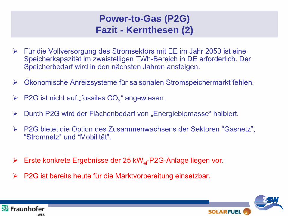
Für die Vollversorgung des Stromsektors mit EE im Jahr 2050 ist eine Speicherkapazität im zweistelligen TWh-Bereich in DE erforderlich. Der Speicherbedarf wird in den nächsten Jahren ansteigen.
Ökonomische Anreizsysteme für saisonalen Stromspeichermarkt fehlen.
P2G ist nicht auf „fossiles CO2“ angewiesen.
Durch P2G wird der Flächenbedarf von „Energiebiomasse“ halbiert.
P2G bietet die Option des Zusammenwachsens der Sektoren “Gasnetz”, “Stromnetz” und “Mobilität”.
Erste konkrete Ergebnisse der 25 kWel-P2G-Anlage liegen vor.
P2G ist bereits heute für die Marktvorbereitung einsetzbar.

Aktueller Stand der Power-to-Gas – Technologie (P2G) - Inhalt -
Ziel SNG-Herstellungspfade aus Erneuerbaren EnergienErgebnisse der 25 kWel -P2G-AnlageP2G-WirkungsgradFazit
KernthesenFuE-BedarfHandlungsempfehlungenweiteres Vorgehen
SNG: Substitute
Natural
Gas
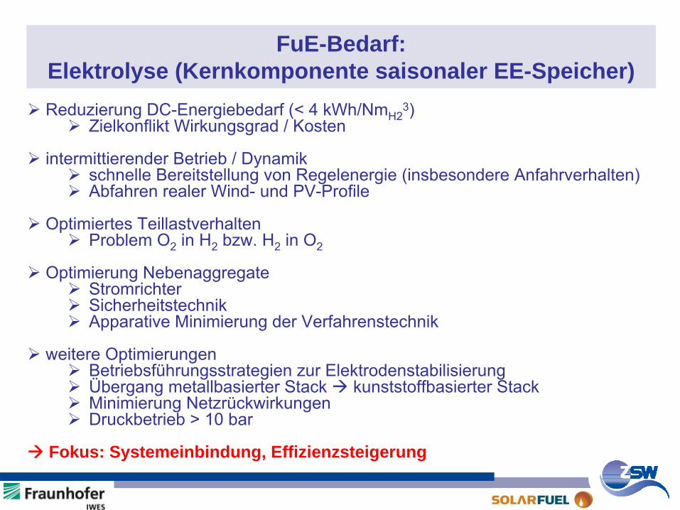
FuE-Bedarf: Elektrolyse (Kernkomponente saisonaler EE-Speicher)Reduzierung DC-Energiebedarf (< 4 kWh/NmH2
3)Zielkonflikt Wirkungsgrad / Kosten
intermittierender Betrieb / Dynamikschnelle Bereitstellung von Regelenergie (insbesondere Anfahrverhalten)Abfahren realer Wind- und PV-Profile
Optimiertes TeillastverhaltenProblem O2 in H2 bzw. H2 in O2
Optimierung NebenaggregateStromrichterSicherheitstechnikApparative Minimierung der Verfahrenstechnik
weitere OptimierungenBetriebsführungsstrategien zur ElektrodenstabilisierungÜbergang metallbasierter Stack kunststoffbasierter StackMinimierung NetzrückwirkungenDruckbetrieb > 10 bar
Fokus: Systemeinbindung, Effizienzsteigerung
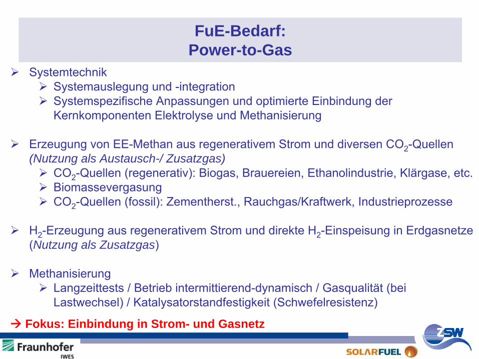
FuE-Bedarf: Power-to-Gas
SystemtechnikSystemauslegung und -integrationSystemspezifische Anpassungen und optimierte Einbindung der Kernkomponenten Elektrolyse und Methanisierung
Erzeugung von EE-Methan aus regenerativem Strom und diversen CO2-Quellen (Nutzung als Austausch-/ Zusatzgas)
CO2-Quellen (regenerativ): Biogas, Brauereien, Ethanolindustrie, Klärgase, etc.BiomassevergasungCO2-Quellen (fossil): Zementherst., Rauchgas/Kraftwerk, Industrieprozesse
H2-Erzeugung aus regenerativem Strom und direkte H2-Einspeisung in Erdgasnetze (Nutzung als Zusatzgas)
MethanisierungLangzeittests / Betrieb intermittierend-dynamisch / Gasqualität (bei Lastwechsel) / Katalysatorstandfestigkeit (Schwefelresistenz)
Fokus: Einbindung in Strom- und Gasnetz

Aktueller Stand der Power-to-Gas – Technologie (P2G) - Inhalt -
Ziel SNG-Herstellungspfade aus Erneuerbaren EnergienErgebnisse der 25 kWel -P2G-AnlageP2G-WirkungsgradFazit
KernthesenFuE-BedarfHandlungsempfehlungenweiteres Vorgehen
SNG: Substitute
Natural
Gas
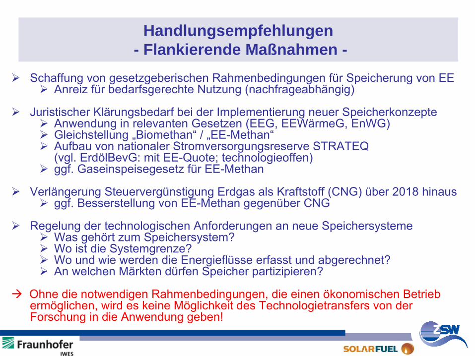
Handlungsempfehlungen - Flankierende Maßnahmen -
Schaffung von gesetzgeberischen Rahmenbedingungen für Speicherung von EEAnreiz für bedarfsgerechte Nutzung (nachfrageabhängig)
Juristischer Klärungsbedarf bei der Implementierung neuer SpeicherkonzepteAnwendung in relevanten Gesetzen (EEG, EEWärmeG, EnWG)Gleichstellung „Biomethan“ / „EE-Methan“Aufbau von nationaler Stromversorgungsreserve STRATEQ(vgl. ErdölBevG: mit EE-Quote; technologieoffen)ggf. Gaseinspeisegesetz für EE-Methan
Verlängerung Steuervergünstigung Erdgas als Kraftstoff (CNG) über 2018 hinausggf. Besserstellung von EE-Methan gegenüber CNG
Regelung der technologischen Anforderungen an neue Speichersysteme Was gehört zum Speichersystem?Wo ist die Systemgrenze?Wo und wie werden die Energieflüsse erfasst und abgerechnet?An welchen Märkten dürfen Speicher partizipieren?
Ohne die notwendigen Rahmenbedingungen, die einen ökonomischen Betrieb ermöglichen, wird es keine Möglichkeit des Technologietransfers von der Forschung in die Anwendung geben!
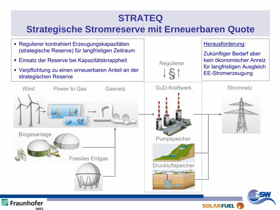
STRATEQ Strategische Stromreserve mit Erneuerbaren Quote
Wind Power to Gas GuD-KraftwerkGasnetz Stromnetz
BiogasanlagePumpspeicher
DruckluftspeicherFossiles Erdgas
Herausforderung:
Zukünftiger Bedarf aber kein ökonomischer Anreiz für langfristigen Ausgleich EE-Stromerzeugung
Regulierer
Regulierer kontrahiert Erzeugungskapazitäten (strategische Reserve) für langfristigen Zeitraum
Einsatz der Reserve bei Kapazitätsknappheit
Verpflichtung zu einen erneuerbaren Anteil an der strategischen Reserve
STRATEQ Erläuterung (1)
Hintergrund:
•
Neben kurzfristigem Ausgleich wird in Zukunft verstärkt saisonaler Ausgleich benötigt
Herausforderung:
•
Langfristspeicher (Zyklen ca. 2 Wochen und größer) lassen sich im bestehenden Marktdesign nur schwer wirtschaftlich darstellen
Wie können Anreize für Langfristspeicherung gesetzt werden?
Lösungsansatz:
•
Strategische Stromreserve mit Erneuerbaren-Energien-Quote (STRATEQ)
•
Anlehnung an Strategische Reserven im Bereich fossiler Brennstoffe
Bestimmte Menge Energie und Erzeugungsleistung wird bereitgehalten, um in Engpasssituationen elektrische Energie erzeugen zu können
(Steigende) EE-Quote gewährleistet langfristig CO2-arme Reserve
STRATEQ Erläuterung (2)
Umsetzung:
•
Strategische Reserve (-Menge) und EE-Quote
wird durch unabhängigen Regulierer festgelegt und versteigert
•
Erzeuger garantiert Bereitstellung von Energie und Erzeugungsleistung und erhält dafür Gebotspreis
•
Abruf im Falle von Engpässen durch Regulierer
Design ähnlich dem bestehenden Regelenergiemarkt, allerdings langfristig orientiert
Chancen und Risiken (Auswahl):
•
Technologieoffenes Konzept
•
Geringe Eingriffe ins bestehende System, relativ einfach und flexibel umsetzbar
•
Festlegung der Größe der Reserve und Kriterien für deren Einsatz
•
Regelmäßige Anpassung der Reserve aufgrund des EE-Zubaus
mindert ggf. die Investitionssicherheit
Aktueller Stand der Power-to-Gas – Technologie (P2G) - Inhalt -
Ziel SNG-Herstellungspfade aus Erneuerbaren EnergienErgebnisse der 25 kWel -P2G-AnlageP2G-WirkungsgradFazit
KernthesenFuE-BedarfHandlungsempfehlungenweiteres Vorgehen
SNG: Substitute
Natural
Gas
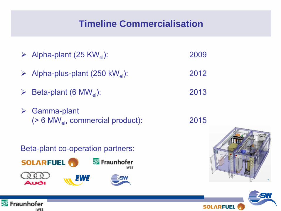
Timeline Commercialisation
Alpha-plant (25 KWel): 2009
Alpha-plus-plant (250 kWel): 2012
Beta-plant (6 MWel): 2013
Gamma-plant(> 6 MWel
, commercial product):
2015
Beta-plant co-operation partners:
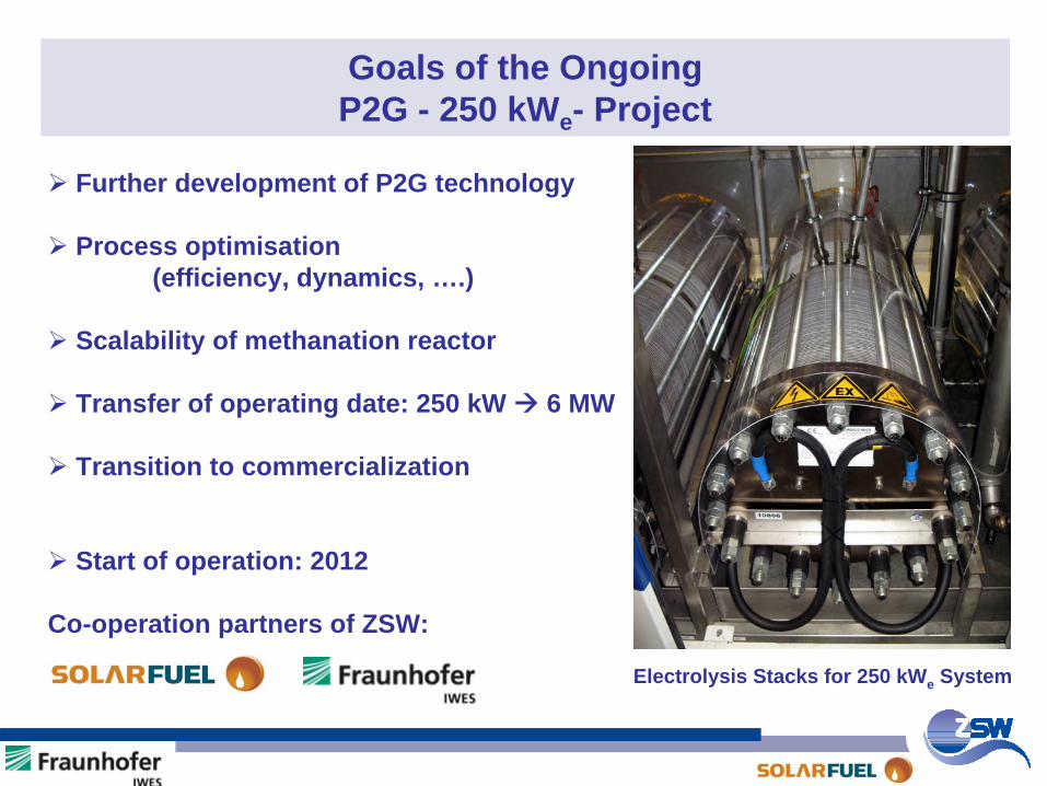
Goals of the Ongoing P2G - 250 kWe - Project
Further development of P2G technology
Process optimisation(efficiency, dynamics, ….)
Scalability of methanation reactor
Transfer of operating date: 250 kW 6 MW
Transition to commercialization
Start of operation: 2012
Co-operation partners of ZSW:
Electrolysis Stacks for 250 kWe System
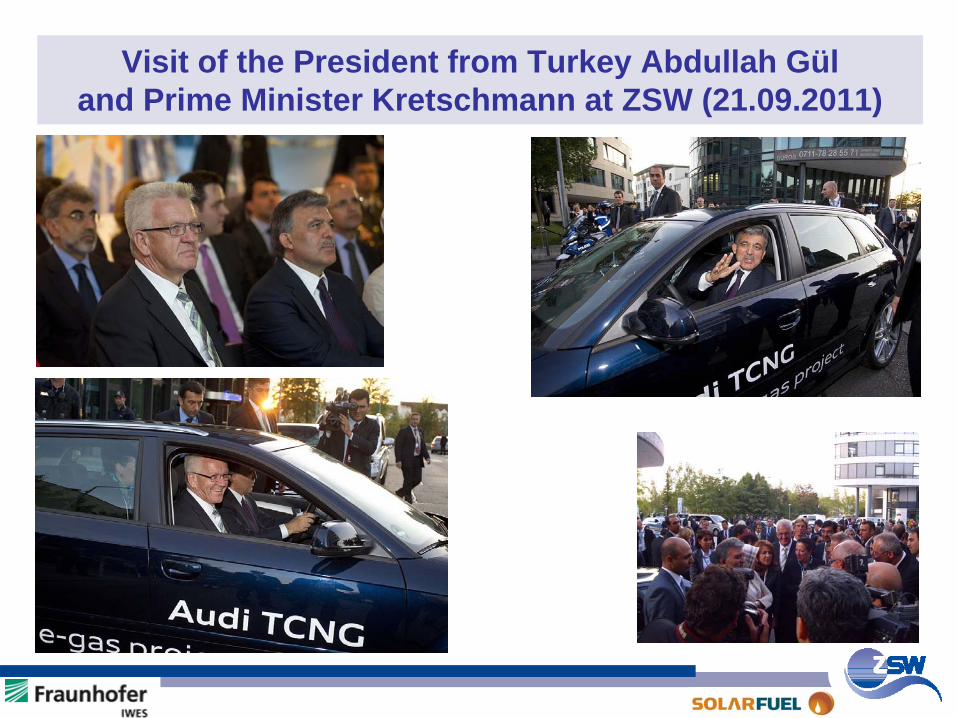
Visit of the President from Turkey Abdullah Gül and Prime Minister Kretschmann at ZSW (21.09.2011)
An interesting discussion !
Thanks for your kind attention.
Recommended