In-mine study of high-expansion firefighting foam
L.L. Chasko Physical science technician, National Institute for Occupational Safety and Health, Pittsburgh, PA
R.S. Conti NIOSH, Pittsburgh, PA (Deceased)
R.L. Derick Consultant, Derick Mining & Safety, L.L.C., Fort Collins, Colorado
(Retired from Twentymile Coal Company)
M.R. Krump Atlanta, Georgia (Retired from Twentymile Coal Company)
C.P. Lazzara, Ph.D. Pittsburgh, PA (Retired from NIOSH)
AbstractA mine fire is one of the most challenging safety issues facing a mine operator and can occur at any location underground. The National Institute for Occupational Safety and Health (NIOSH) and the Twentymile Coal Mine, CO, conducted in-mine experiments to determine the capability of high-expansion foam for addressing underground fires. The tests were conducted in sloping entries with high-capacity diesel-powered foam generators. The following results were observed: a well-designed, maintained and properly operated high-expansion foam generator can propagate a foam plug hundreds of feet in steep upward-sloping (20%) multiple entries against a ventilation pressure; stoppings and partitions designed to contain the foam plug in upward-sloping entries must be substantially constructed; and the predicted quantity of foam concentrate can be significantly less than the actual amount used, due to foam losses, such as bubble breakage on dry surfaces. This paper describes the production of high-expansion fire-fighting foam and discusses the in-mine experimental tests and results.
IntroductionWhen an underground mine fire cannot be directly attacked
due to heat, smoke or hazardous roof conditions, high-expansion foam may be one way to control the fire from a remote, safe underground location. High-expansion foam is a blanketing and cooling agent produced by a combination of water, air and foam concentrate. High-expansion foam is a means of conveying water directly to the fire, diluting the oxygen concentration by producing steam and blocking both air currents to the fire and radiant energy from the burning fuel. The foam concentrate, combined with proper amounts of air and water and expelled through an application device, will form finished foam appro-priate for firefighting applications. The foam expansion ratio is the volume of foam to the volume of foam solution required to produce the foam. High-expansion foam has an expansion ratio greater than 200 to 1.
This paper details how foam generation can be used to
combat large fires in underground mines and describes experi-ments conducted by the National Institute for Occupational Safety and Health (NIOSH) and the Twentymile Coal Mine, Colorado. The underground tests were conducted in sloping mine entries with high-capacity diesel-powered foam generators and three test scenarios are reviewed, along with their potential applications to mine fires.
Background on foam generation and firefighting in mines
In its simplest form, a large capacity, blower-type high-expansion foam generator >142 m3/min (>5,000 cfm) is made up of an electric or diesel-powered fan, a screen and a foam concentrate proportioner. The proportioner mixes the foam concentrate with water at the desired rate. The solution is dis-charged through nozzles onto the screen. The high-expansion foam is formed as air from the fan passes through the screen
wetted with the solution. Additional design information on high-expansion foam systems can be found in National Fire Protection Associaton Standard 11, Low-, Medium-, and High-Expansion Foam (NFPA, 2005).
Before a foam system is implemented, the mine operator should consider the training and equipment needed, and the amount and type of foam concentrate required. Once the equip-ment and supplies are purchased, a plan must be developed for using foam in the mine. Foam-generating equipment should be compatible with the mine water system in regards to pres-sure and fittings. Whether using foam or another means of fire extinguishment, the mine operator should have an organized strategy for fast response, including a group of well-trained miners ready for an emergency situation. The mine should also have periodic drills to test the effectiveness of the fire-fighting plan.
Foam concentrates are designed to cover the widest possible range of firefighting applications. Selection of foam concentrate should be based on foam characteristics that are appropriate for each particular fire hazard and the water quality. Some of the foam concentrates available include: aqueous film-forming foam for flammable liquid fires, aqueous film-forming foam for both hydrocarbon and water-soluble liquid fuel fires and high-expansion foam for three-dimensional fires where total flooding is the objective, such as in coal mines.
Once the proper foam concentrate is selected, it must be mixed in the right proportion with water. Foam concentrates are available for mixing with water in various concentra-tions, such as 2%, 6%, etc. Foam proportioners are designed to introduce the proper amount of foam concentrate into the water stream. Eductors that work on the Venturi principle are the most common form of proportioning equipment. Water is introduced, under pressure, at the inlet of the eductor. The eductor reduces the orifice available for the water to pass through and thus increases the water velocity. This creates a pressure drop that, in turn, applies suction to the pickup tube. As the foam concentrate is pulled up the tube, it passes through a metering valve that introduces the correct amount into the water stream. In-line eductors are matched systems that require specific water pressures for operation. Therefore, the manufacturer’s recommendations for hose size, hose length and water pressure must be considered before purchasing an in-line eductor system.
An adequate supply of foam concentrate should be readily available at the mine in 19-L (5-gal) pails, 114-L (30-gal) drums or 208-L (55-gal) drums. If drums are used, transportation and compatibility of the eductor should be considered. Arrange-ments should also be made beforehand to obtain additional foam concentrate from nearby mines or a local distributor.
When storing foam concentrate, the manufacturer’s recom-mendations should be followed. Storage temperatures at the mine should be in the recommended range. Foam concentrate should not be stored outside if there is a risk of freezing. A typical temperature range for foam concentrate storage is 1.7° C (35° F) to 49° C (120º F). The cloud point, or when the concentrate becomes gelatinous, is usually below the lowest temperature specified. When foam concentrate becomes cloudy, it cannot produce quality foam. This same temperature range should be maintained when transporting the foam concentrate. Care must be taken to ensure that plastic containers are not cracked or dented and 19-L (5-gal) plastic pails of foam concentrate should not be stacked more than three containers high.
High-expansion foam cannot control a fire unless the foam
plug reaches the fire. A fire is considered under control when the burning is reduced to the point that extinguishing the fire by direct attack with water lines is easily and safely accomplished. Attempts have been made to push foam plugs into the burning entry ahead (downwind) of large fires. The tremendous heat and hot gases on the downwind side of the fire will break the foam and most of it will be heated into steam and blow down the entry away from the fire. However, if foam is pushed into the fire on the upwind side of the fire, the foam will reach and cool the fire. It should also be noted that high-expansion foam generators may not produce high quality foam if the intake air is heavily contaminated with smoke.
Once the foam-making process is initiated, the foam generator should not be turned off unless this decision is carefully analyzed, or unless the fire is controlled. Even if the water supply fails or the foam concentrate is depleted, the foam generator itself should be left on to maintain a positive pressure against the foam plug. When the foam generator is turned off, the foam plug has a tendency to relax, creating a void space near the roof along the length of the foam plug. This void space may cause a sudden rush of air to the fire area. Additional information on the use of high-expansion foam and other methods to combat mine fires can be found in various references (Mitchell, 1996; Bird et al., 1999; Conti, 1994; Havener, 1975; Nagy et al., 1960).
Foam generator partitions and operatorsTo effectively use high-expansion foam for remotely fight-
ing fires in underground mine entries, it is often necessary to construct, at some distance from the fire, a partition or stopping in fresh air to separate the foam generator and its operators from toxic fire products and to contain the foam. If this is not done, the high-expansion foam could flow back over the foam generator and never reach the fire. This problem is especially acute when the fire is found uphill in a sloping entry. The partition also limits mine ventilation air from reaching the fire. Concrete block, wood, plastic sheeting, mine brattice or similar materials have been used for such partitions. Construction of such partitions can be a time-consuming and labor-intensive process. Often, mine entries have irregular dimensions to which the partition must conform to avoid leakage around the periphery. After the partition is constructed, a hole must be cut through it to allow passage of the high-expansion foam from the foam generator to the fire. During an underground training exercise for mine rescue teams and fire brigades in an operating coal mine, it required more than an hour to construct a partition from wood, metal and brattice, and to start the foam propagating up the mine entry.
To address some of the difficulties of constructing a partition for high-expansion foam generators, an inflatable feed-tube partition (IFTP) was developed (Conti and Lazzara, 1995; Conti, 1995). The IFTP is a lightweight, nylon rectangular bag that can be inflated by a permissible fan, a compressed air line or an inert gas source. The device can rapidly block large under-ground mine openings in 15 min and simultaneously provide a feed tube for high-expansion foam. This allows firefighting foam to freely flow to the fire site and control the fire. Despite its advantages, the IFTP would not be useful when pushing a foam plug a significant distance up a steeply sloping entry (>8 percent). In this case, a more substantial partition is required.
As high-expansion foam moves down an entry, a continuous shrinkage process occurs. A foam bubble cannot exist once touching a dry surface; it will collapse, wetting the surface so
that the next foam bubble can replace it. Thus, as a foam plug advances, there is a constant bubble collapse. This shrinkage takes place on the leading edge of the foam plug. Due to this continuous shrinkage, water starts to collect under the foam plug. In an upward sloping entry, the water flows back towards the foam generator on the low side of the entry. A considerable amount of water can build up on the foam side of the partition, causing some partitions to fail. To reduce the water buildup, a pipe must be laid on the floor along the low side of the entry and under the partition. The water flows through the pipe and down the entry. The size of pipe is scaled to the output of the foam generator. For example, at least a 15-cm (6-in.) diameter pipe should be used with a generator that produces 170 m3/min (6,000 cfm) or greater.
The high-expansion foam generator at a mine site would most likely be operated by members of the fire brigade or mine rescue team. The operators should actually test the foam generator in their mine during training drills and propagate high-expansion foam in the passageways. This also entails erecting a suitable partition to be interfaced with the foam generator and/or other stoppings to contain the foam plug. They should ensure compatibility of the foam concentrate and mine water supply, proper fittings and an adequate supply of foam concentrate.
Foam firefighting efforts during mine firesDue to its unsuccessful use at the Wilberg Mine Fire, UT, in
December 1984, some doubt has arisen about the effectiveness of high-expansion foam for controlling a large underground coal mine fire (Huntley et al., 1987). However, there is also some question as to whether the optimum foam concentrate was being utilized with the foam generator, whether the foam concentrate was in proper condition and whether simultaneous rock dusting was taking place. Small and numerous particles of rock dust can quickly destroy the foam bubbles. In fact, an easy and effective way to walk through a plug of foam is to create a path by hand-spreading rock dust into the blanket of foam.
Probably the largest attempt to use high-expansion foam to fight a very large underground fire occurred at the Orchard Valley Coal Mine, CO, in June 1986 (Timko et al., 1987). Miners started fighting the fire with a supply of fifteen 208-L (55-gal) drums of foam concentrate. Additional foam concen-trate was obtained during the ordeal from several other mines and a local vendor. Unfortunately, sufficient quantities of foam concentrate to quench the fire were unavailable and as soon as the concentrate was depleted, control of the fire was lost. It is likely that this effort would have been successful if the foam concentrate supply were not exhausted. At one point during the fire, 1,700 m3/min (60,000 cfm) of high-expansion foam was being pumped into the mine through three portals and shafts. Since gas chromatograph samples were obtained during the initial hours of the fire, valuable information was learned dur-ing this firefighting effort. When the foam concentrate supply was exhausted, the oxygen decreased and the carbon monoxide increased as the fire grew in size and changed from a fuel-starved fire to a fuel-rich fire. This indicated the effectiveness of the foam in limiting the spread of the fire. Further, the additional safety benefit for miners potentially trapped inby a fire while a large-scale firefighting effort is underway was apparent due to the lower carbon monoxide concentration measured during the application of the foam.
The Deserado Mine Fire, CO, in February 1996 (Gore, 1997) occurred in the tailgate area of a longwall face. The use
of high-expansion foam was proposed by the operator as part of the firefighting plan. However, the plan was not accepted by the U.S. Mine Safety and Health Administration (MSHA). Several concerns surfaced, including: 1) whether the foam plug would travel from the headgate along the face up an 8% incline to where the fire was located; 2) lack of information on the possible downwind gas constituents as the fire was sup-pressed by the high-expansion foam and 3) the effect the foam plug could have on restricting the ventilation and the potential that methane might migrate out of the gob to the fire, creating an explosion risk to underground personnel.
Calculating foam concentrate and water supply needs
A few common questions arise regarding the use of high-expansion foam for controlling an underground mine fire, including, “What is an adequate water supply?” and “How much foam concentrate is required?” In the context of a 24-hr period, these questions can be answered by considering the mine’s characteristics, such as entry size and water supply. The following example is used to illustrate how much water and foam concentrate would be needed to sustain firefighting efforts for Twentymile Mine with a specific foam generator.
In this example, a Jamison 510 m3/min (18,000 cfm) diesel-powered high-expansion (expansion ratio of 1,000 to 1) foam generator is used. According to the operating manual (Jamison, 1993), this generator requires 500 L/min (132 gpm) of foam solution (water and foam concentrate), FS.
The foam concentrate flow rate can be determined by the following equation:
FFR = FS FC (1) where: FFR = Foam concentrate flow rate, L/min (gpm)FS = Foam solution, L/min (gpm)FC = Foam concentrate, percent For this example, for a 2% foam and 500 L/min (132 gpm)
of foam solution, the flow rate of foam concentrate, from Eq. (1), is 10 L/min (2.6 gpm).
The water flow rate can be determined by the following equation:
WFR = FS - FFR (2) where: WFR = Water flow rate, L/min (gpm) When FS is 500 L/min (132 gpm) and FFR is 10 L/min (2.6
gpm), the water flow rate, from Eq. (2), is 490 L/min (129 gpm).For the above example, in one hour of firefighting, approxi-
mately 600 L (159 gal) of foam concentrate and 29,400 L (7,770 gal) of water are required. The amount of high-expansion foam produced from these quantities with the 510 m3/min (18,000 cfm) generator would fill approximately 30,600 m3 (1,080,000 ft3) of entry. However, foam quality, foam bubble breakage and foam turning into steam as the foam plug approaches the fire and contacts the burning material will significantly reduce the predicted volume. For a 24-hr period, about 705,600 L (186,400 gal) of water and approximately 14,400 L (3,800 gal), or one hundred and twenty-six 114-L (30-gal) barrels, of foam concentrate should be on hand or be able to be acquired from
other mines or distributors within that period. Table 1 sum-marizes the above information for the given example.
Table 1 — High-expansion foam calculations.
Foam generator parameters Requirements for1 hr, L (gal)
Requirements for24 hr, L (gal)
m3/min
(cfm)
Foam solution
(water and foam)
L/min (gpm)
Foam concentrate
WFR , L/min
(gpm) Water Foam concentrate Water Foam concentrate%
FFR, L/min
(gpm)
510 5002
10 490 29,400 600 705,600 14,400
(18,000) (132) (2.6) (129) (7,740) (159) (186,000) (3,800)
Underground high-expansion foam experimentsIn partnership with the Twentymile Coal Company (Oak
Creek, CO), a series of experiments was conducted with high-expansion foam in underground mine passageways. Twen-tymile Mine is a slope mine that uses continuous and longwall mining methods to extract the Wadge Seam, a high-volatile C bituminous coal. Only the most significant tests are described in this section, with three scenarios reviewed to represent the different experiments.
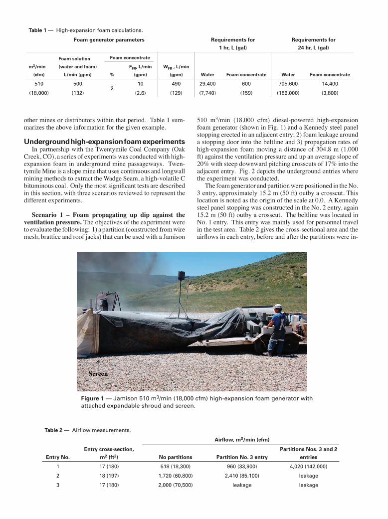
Scenario 1 – Foam propagating up dip against the ventilation pressure. The objectives of the experiment were to evaluate the following: 1) a partition (constructed from wire mesh, brattice and roof jacks) that can be used with a Jamison
510 m3/min (18,000 cfm) diesel-powered high-expansion foam generator (shown in Fig. 1) and a Kennedy steel panel stopping erected in an adjacent entry; 2) foam leakage around a stopping door into the beltline and 3) propagation rates of high-expansion foam moving a distance of 304.8 m (1,000 ft) against the ventilation pressure and up an average slope of 20% with steep downward pitching crosscuts of 17% into the adjacent entry.
Figure 1 — Jamison 510 m3/min (18,000 cfm) high-expansion foam generator with attached expandable shroud and screen.
Fig. 2 depicts the underground entries where the experiment was conducted.
Table 2 — Airflow measurements.
Entry No.Entry cross-section,
m2 (ft2)
Airflow, m3/min (cfm)
No partitions Partition No. 3 entryPartitions Nos. 3 and 2
entries
1 17 (180) 518 (18,300) 960 (33,900) 4,020 (142,000)
2 18 (197) 1,720 (60,800) 2,410 (85,100) leakage
3 17 (180) 2,000 (70,500) leakage leakage
The foam generator and partition were positioned in the No. 3 entry, approximately 15.2 m (50 ft) outby a crosscut. This location is noted as the origin of the scale at 0,0. A Kennedy steel panel stopping was constructed in the No. 2 entry, again 15.2 m (50 ft) outby a crosscut. The beltline was located in No. 1 entry. This entry was mainly used for personnel travel in the test area. Table 2 gives the cross-sectional area and the airflows in each entry, before and after the partitions were in-
stalled in Nos. 3 and 2 entries. The airflow was measured with a handheld vane anemometer where the partitions were to be built in Nos. 3 and 2 entries. As seen in the table, the airflow was significantly increased in the beltline when partitions were constructed in Nos. 3 and 2 entries.
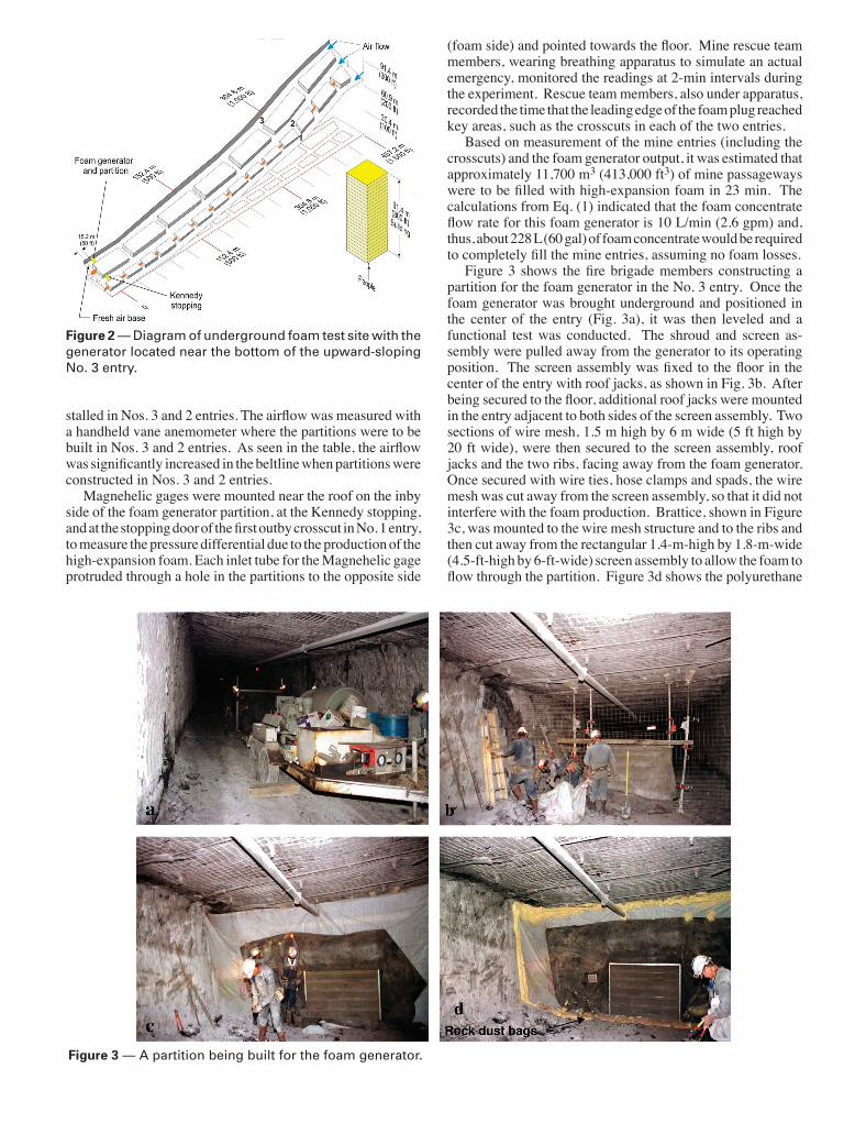
Figure 2 — Diagram of underground foam test site with the generator located near the bottom of the upward-sloping No. 3 entry.
Magnehelic gages were mounted near the roof on the inby side of the foam generator partition, at the Kennedy stopping, and at the stopping door of the first outby crosscut in No. 1 entry, to measure the pressure differential due to the production of the high-expansion foam. Each inlet tube for the Magnehelic gage protruded through a hole in the partitions to the opposite side
(foam side) and pointed towards the floor. Mine rescue team members, wearing breathing apparatus to simulate an actual emergency, monitored the readings at 2-min intervals during the experiment. Rescue team members, also under apparatus, recorded the time that the leading edge of the foam plug reached key areas, such as the crosscuts in each of the two entries.
Based on measurement of the mine entries (including the crosscuts) and the foam generator output, it was estimated that approximately 11,700 m3 (413,000 ft3) of mine passageways were to be filled with high-expansion foam in 23 min. The calculations from Eq. (1) indicated that the foam concentrate flow rate for this foam generator is 10 L/min (2.6 gpm) and, thus, about 228 L (60 gal) of foam concentrate would be required to completely fill the mine entries, assuming no foam losses.
Figure 3 shows the fire brigade members constructing a partition for the foam generator in the No. 3 entry.
Figure 3 — A partition being built for the foam generator.
Once the foam generator was brought underground and positioned in the center of the entry (Fig. 3a), it was then leveled and a functional test was conducted. The shroud and screen as-sembly were pulled away from the generator to its operating position. The screen assembly was fixed to the floor in the center of the entry with roof jacks, as shown in Fig. 3b. After being secured to the floor, additional roof jacks were mounted in the entry adjacent to both sides of the screen assembly. Two sections of wire mesh, 1.5 m high by 6 m wide (5 ft high by 20 ft wide), were then secured to the screen assembly, roof jacks and the two ribs, facing away from the foam generator. Once secured with wire ties, hose clamps and spads, the wire mesh was cut away from the screen assembly, so that it did not interfere with the foam production. Brattice, shown in Figure 3c, was mounted to the wire mesh structure and to the ribs and then cut away from the rectangular 1.4-m-high by 1.8-m-wide (4.5-ft-high by 6-ft-wide) screen assembly to allow the foam to flow through the partition. Figure 3d shows the polyurethane
foam applied to the perimeter of the brattice and wire mesh partition (roof, floor and ribs) to reduce foam leakage. A 15-cm (6-in.) diameter drainpipe was laid on the low side of the entry on the floor, and extended 9 m (30 ft) inby (down dip) past the partition and foam generator. A row of rock dust bags was placed on the mine floor against the partition to direct the broken-down foam and water into this drainpipe. This can also be seen in Fig. 3d.
Figure 4 illustrates the construction of the steel panel stopping in the No. 2 entry by mine rescue team members.
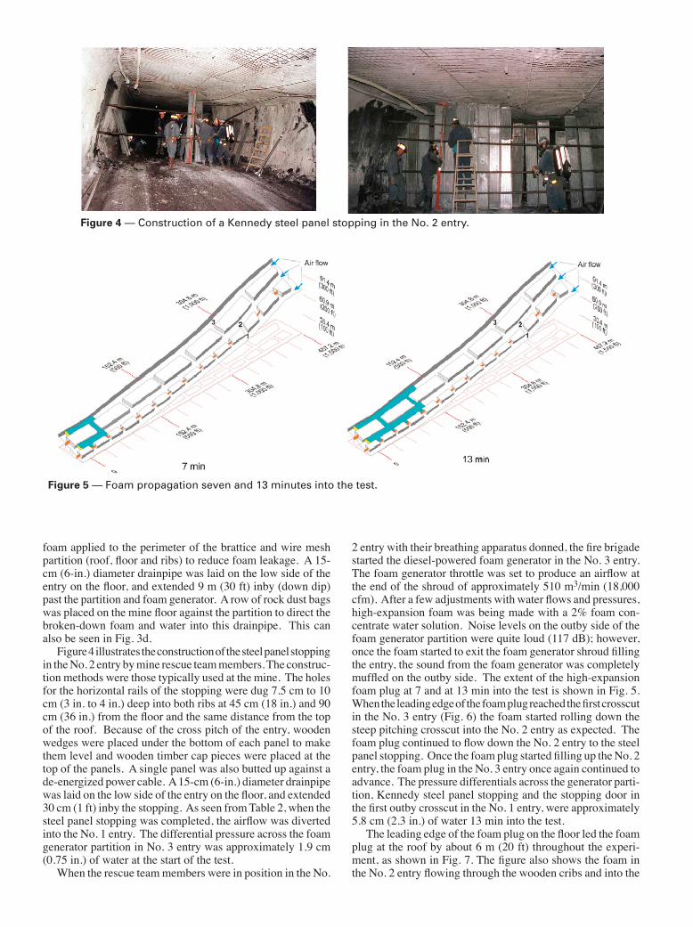
Figure 4 — Construction of a Kennedy steel panel stopping in the No. 2 entry.
The construc-tion methods were those typically used at the mine. The holes for the horizontal rails of the stopping were dug 7.5 cm to 10 cm (3 in. to 4 in.) deep into both ribs at 45 cm (18 in.) and 90 cm (36 in.) from the floor and the same distance from the top of the roof. Because of the cross pitch of the entry, wooden wedges were placed under the bottom of each panel to make them level and wooden timber cap pieces were placed at the top of the panels. A single panel was also butted up against a de-energized power cable. A 15-cm (6-in.) diameter drainpipe was laid on the low side of the entry on the floor, and extended 30 cm (1 ft) inby the stopping. As seen from Table 2, when the steel panel stopping was completed, the airflow was diverted into the No. 1 entry. The differential pressure across the foam generator partition in No. 3 entry was approximately 1.9 cm (0.75 in.) of water at the start of the test.
When the rescue team members were in position in the No.
2 entry with their breathing apparatus donned, the fire brigade started the diesel-powered foam generator in the No. 3 entry. The foam generator throttle was set to produce an airflow at the end of the shroud of approximately 510 m3/min (18,000 cfm). After a few adjustments with water flows and pressures, high-expansion foam was being made with a 2% foam con-centrate water solution. Noise levels on the outby side of the foam generator partition were quite loud (117 dB); however, once the foam started to exit the foam generator shroud filling the entry, the sound from the foam generator was completely muffled on the outby side. The extent of the high-expansion foam plug at 7 and at 13 min into the test is shown in Fig. 5.
Figure 5 — Foam propagation seven and 13 minutes into the test.
When the leading edge of the foam plug reached the first crosscut in the No. 3 entry (Fig. 6) the foam started rolling down the steep pitching crosscut into the No. 2 entry as expected. The foam plug continued to flow down the No. 2 entry to the steel panel stopping. Once the foam plug started filling up the No. 2 entry, the foam plug in the No. 3 entry once again continued to advance. The pressure differentials across the generator parti-tion, Kennedy steel panel stopping and the stopping door in the first outby crosscut in the No. 1 entry, were approximately 5.8 cm (2.3 in.) of water 13 min into the test.
The leading edge of the foam plug on the floor led the foam plug at the roof by about 6 m (20 ft) throughout the experi-ment, as shown in Fig. 7. The figure also shows the foam in the No. 2 entry flowing through the wooden cribs and into the
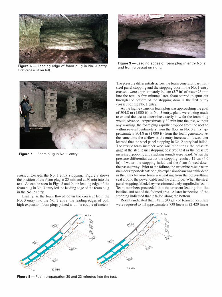
crosscut towards the No. 1 entry stopping. Figure 8 shows the position of the foam plug at 23 min and at 30 min into the test. As can be seen in Figs. 8 and 9, the leading edge of the foam plug in No. 3 entry led the leading edge of the foam plug in the No. 2 entry.
Figure 6 — Leading edge of foam plug in No. 3 entry, first crosscut on left.
Figure 7 — Foam plug in No. 2 entry.
Figure 8 — Foam propagation 30 and 23 minutes into the test.
Figure 9 — Leading edges of foam plug in entry No. 2 and from crosscut on right.
Usually, as the foam flowed down the crosscut from the No. 3 entry into the No. 2 entry, the leading edges of both high-expansion foam plugs joined within a couple of meters.
The pressure differentials across the foam generator partition, steel panel stopping and the stopping door in the No. 1 entry crosscut were approximately 9.4 cm (3.7 in) of water 23 min into the test. A few minutes later, foam started to spurt out through the bottom of the stopping door in the first outby crosscut of the No. 1 entry.
As the high-expansion foam plug was approaching the goal of 304.8 m (1,000 ft) in No. 3 entry, plans were being made to extend the test to determine exactly how far the foam plug would advance. Approximately 32 min into the test, without any warning, the foam plug rapidly dropped from the roof to within several centimeters from the floor in No. 3 entry, ap-proximately 304.8 m (1,000 ft) from the foam generator. At the same time the airflow in the entry increased. It was later learned that the steel panel stopping in No. 2 entry had failed. The rescue team member who was monitoring the pressure gage at the steel panel stopping observed that as the pressure increased, popping and cracking sounds were heard. When the pressure differential across the stopping reached 12 cm (4.6 in) of water, the stopping failed and the foam flowed down the passageway. Prior to the failure, the two mine rescue team members reported that the high-expansion foam was ankle deep in that area because foam was leaking from the polyurethane seal around the power cable and the drainpipe. When the steel panel stopping failed, they were immediately engulfed in foam. Team members proceeded into the crosscut leading into the beltline and out of the foamed area. A later inspection of the stopping indicated that it failed along the bottom.
Results indicated that 342 L (90 gal) of foam concentrate were required to fill approximately 738 linear m (2,420 linear
ft) of entries, or 11,500 m3 (405,000 ft3) in 32 min. The foam propagation rate was 34 m/min (112 fpm) over the first 46 m (150 ft) and then averaged 22 m/min (73 fpm) over the remain-ing distance as the No. 3 and No. 2 entries were being filled. The foam plug propagated approximately 304.8 m (1,000 ft) in two entries, with an increase in elevation of about 60.9 m (200 ft) - the equivalent of a 20-story building. The foam generator partition and stopping door had minor leaks around their perimeters.
During the experiment, the revolutions per minute (rpm) of the diesel engine were increased from 1,700 rpm (start) to 2,500 rpm (end) to maintain the optimum airflow for foam making. This foam generator can produce quality foam at pressures up to 25.4 cm (10 in.) of water. Figure 10 shows the differential pressure across the foam generator partition in No. 3 entry with time.
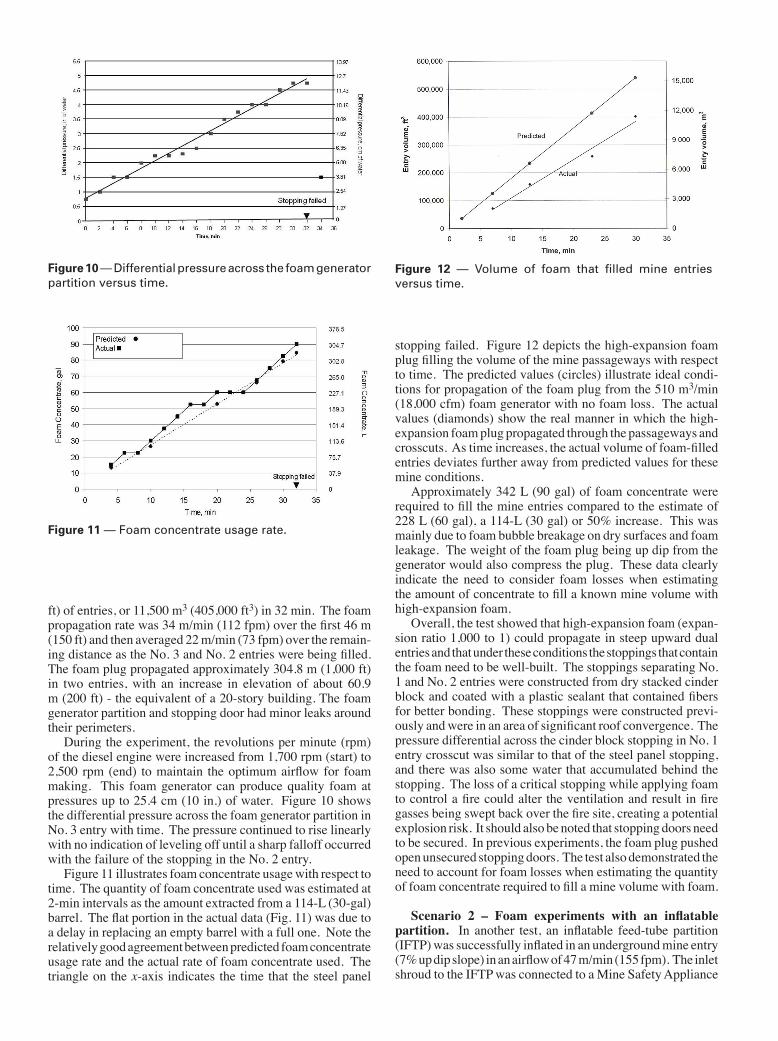
Figure 10 — Differential pressure across the foam generator partition versus time.
The pressure continued to rise linearly with no indication of leveling off until a sharp falloff occurred with the failure of the stopping in the No. 2 entry.
Figure 11 illustrates foam concentrate usage with respect to time.
Figure 11 — Foam concentrate usage rate.
The quantity of foam concentrate used was estimated at 2-min intervals as the amount extracted from a 114-L (30-gal) barrel. The flat portion in the actual data (Fig. 11) was due to a delay in replacing an empty barrel with a full one. Note the relatively good agreement between predicted foam concentrate usage rate and the actual rate of foam concentrate used. The triangle on the x-axis indicates the time that the steel panel
stopping failed. Figure 12 depicts the high-expansion foam plug filling the volume of the mine passageways with respect to time.
Figure 12 — Volume of foam that filled mine entries versus time.
The predicted values (circles) illustrate ideal condi-tions for propagation of the foam plug from the 510 m3/min (18,000 cfm) foam generator with no foam loss. The actual values (diamonds) show the real manner in which the high-expansion foam plug propagated through the passageways and crosscuts. As time increases, the actual volume of foam-filled entries deviates further away from predicted values for these mine conditions.
Approximately 342 L (90 gal) of foam concentrate were required to fill the mine entries compared to the estimate of 228 L (60 gal), a 114-L (30 gal) or 50% increase. This was mainly due to foam bubble breakage on dry surfaces and foam leakage. The weight of the foam plug being up dip from the generator would also compress the plug. These data clearly indicate the need to consider foam losses when estimating the amount of concentrate to fill a known mine volume with high-expansion foam.
Overall, the test showed that high-expansion foam (expan-sion ratio 1,000 to 1) could propagate in steep upward dual entries and that under these conditions the stoppings that contain the foam need to be well-built. The stoppings separating No. 1 and No. 2 entries were constructed from dry stacked cinder block and coated with a plastic sealant that contained fibers for better bonding. These stoppings were constructed previ-ously and were in an area of significant roof convergence. The pressure differential across the cinder block stopping in No. 1 entry crosscut was similar to that of the steel panel stopping, and there was also some water that accumulated behind the stopping. The loss of a critical stopping while applying foam to control a fire could alter the ventilation and result in fire gasses being swept back over the fire site, creating a potential explosion risk. It should also be noted that stopping doors need to be secured. In previous experiments, the foam plug pushed open unsecured stopping doors. The test also demonstrated the need to account for foam losses when estimating the quantity of foam concentrate required to fill a mine volume with foam.
Scenario 2 – Foam experiments with an inflatable partition. In another test, an inflatable feed-tube partition (IFTP) was successfully inflated in an underground mine entry (7% up dip slope) in an airflow of 47 m/min (155 fpm). The inlet shroud to the IFTP was connected to a Mine Safety Appliance
Company (MSA) 680 m3/min (24,000 cfm) high-expansion foam generator. After the foam plug reached 23 m (75 ft) (in less than 2 min), excessive water accumulated in the shroud and water and foam spurted out of the generator’s air intake. The generator was stopped and water in the shroud released. The experiment continued and the foam plug advanced to 35 m (115 ft), when the same problem occurred. The pressure differential across the generator at this time was 2.3 cm (0.9 in) of water.
After discussions with mine personnel on the cause of the failure, the test was stopped. Visual observations of the foam plug revealed that the foam was very dense, similar to shaving cream. Several suggestions were offered on the probable cause: defective water sprays on the generator, incorrect percentage of water and foam concentrate, transport of the foam concen-trate during extremely cold weather and a recent additive to the mine water supply to increase its wetting ability. Water samples were collected and analyzed and MSA was contacted to evaluate the foam generator.
The underground water supply for Twentymile Mine is obtained from three independent aboveground sources, and varies considerably in hardness from 700 mg/L up to 3,100 mg/L (200 mg/L is normal for drinking water). Previous ex-periments showed that a 2%, high-expansion foam concentrate produced quality foam with the MSA 680 m3/min (24,000 cfm) foam generator. However, follow-up experiments showed that poor quality foam was produced with the same generator and concentrate. Samples of the foam concentrate were tested by the manufacturer, who indicated that the concentrate was not compromised and that the foam generator was operating within specifications. Water tests showed that the sample col-lected was extremely hard and not compatible with the foam concentrate. A saltwater foam concentrate for the hard water was recommended. In spite of the problems encountered, it was important that these issues surfaced during testing rather than during a mine fire.
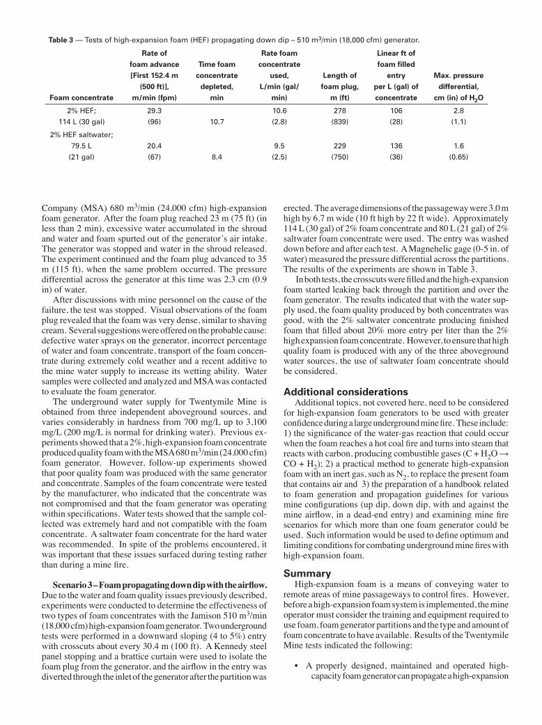
Scenario 3 – Foam propagating down dip with the airflow. Due to the water and foam quality issues previously described, experiments were conducted to determine the effectiveness of two types of foam concentrates with the Jamison 510 m3/min (18,000 cfm) high-expansion foam generator. Two underground tests were performed in a downward sloping (4 to 5%) entry with crosscuts about every 30.4 m (100 ft). A Kennedy steel panel stopping and a brattice curtain were used to isolate the foam plug from the generator, and the airflow in the entry was diverted through the inlet of the generator after the partition was
erected. The average dimensions of the passageway were 3.0 m high by 6.7 m wide (10 ft high by 22 ft wide). Approximately 114 L (30 gal) of 2% foam concentrate and 80 L (21 gal) of 2% saltwater foam concentrate were used. The entry was washed down before and after each test. A Magnehelic gage (0-5 in. of water) measured the pressure differential across the partitions. The results of the experiments are shown in Table 3.
Table 3 — Tests of high-expansion foam (HEF) propagating down dip – 510 m3/min (18,000 cfm) generator.
Foam concentrate
Rate offoam advance[First 152.4 m
(500 ft)],m/min (fpm)
Time foam concentrate
depleted,min
Rate foam concentrate
used,L/min (gal/
min)
Length offoam plug,
m (ft)
Linear ft of foam filled
entryper L (gal) of concentrate
Max. pressuredifferential,
cm (in) of H2O
2% HEF;
114 L (30 gal)
29.3
(96) 10.7
10.6
(2.8)
278
(839)
106
(28)
2.8
(1.1)
2% HEF saltwater;
79.5 L
(21 gal)
20.4
(67) 8.4
9.5
(2.5)
229
(750)
136
(36)
1.6
(0.65)
In both tests, the crosscuts were filled and the high-expansion foam started leaking back through the partition and over the foam generator. The results indicated that with the water sup-ply used, the foam quality produced by both concentrates was good, with the 2% saltwater concentrate producing finished foam that filled about 20% more entry per liter than the 2% high expansion foam concentrate. However, to ensure that high quality foam is produced with any of the three aboveground water sources, the use of saltwater foam concentrate should be considered.
Additional considerationsAdditional topics, not covered here, need to be considered
for high-expansion foam generators to be used with greater confidence during a large underground mine fire. These include: 1) the significance of the water-gas reaction that could occur when the foam reaches a hot coal fire and turns into steam that reacts with carbon, producing combustible gases (C + H2O → CO + H2); 2) a practical method to generate high-expansion foam with an inert gas, such as N2, to replace the present foam that contains air and 3) the preparation of a handbook related to foam generation and propagation guidelines for various mine configurations (up dip, down dip, with and against the mine airflow, in a dead-end entry) and examining mine fire scenarios for which more than one foam generator could be used. Such information would be used to define optimum and limiting conditions for combating underground mine fires with high-expansion foam.
SummaryHigh-expansion foam is a means of conveying water to
remote areas of mine passageways to control fires. However, before a high-expansion foam system is implemented, the mine operator must consider the training and equipment required to use foam, foam generator partitions and the type and amount of foam concentrate to have available. Results of the Twentymile Mine tests indicated the following:
• A properly designed, maintained and operated high-capacity foam generator can propagate a high-expansion
foam plug at least 304.8 m (1,000 ft) in steep (20%) upward multiple entries against a ventilation pressure.
• The actual amount of foam concentrate required to fill a given volume of mine entry with high-expansion foam could be significantly more than the estimated amount. This is due to the mine-specific conditions, bubble breakage and foam compression. In the in-mine tests in steep upward sloping multiple entries described in this report (Scenario 1), the actual amount of foam concentrate required to fill about 738 linear m (2,420 linear ft) of entries exceeded the predicted amount by 50%—228 L (60 gal) predicted, 342 L (90 gal) actual.
• Temporary and permanent stoppings need to be well-constructed to minimize foam leakage and withstand the pressure created by the foam plug. Foam genera-tor partitions and other stoppings may require a drain, especially in upward sloping entries, to relieve water buildup behind the structures. Stopping doors need to be well-secured or the foam plug can force the door open and allow the foam to pass through.
• Compatibility issues of the high-expansion foam con-centrate and water supply, such as water hardness and acidity, must be addressed to ensure the production of high-quality finished foam. Foam concentrate should be stored at recommended temperatures.
• On-site foam generators must be tested underground at regular intervals to ensure their proper operation and maintain the skill levels of the operators. The mine should have a strategy for fast response and a group of well-trained miners ready on all shifts for an emer-gency situation.
DedicationThis report was initially prepared by Ronald S. Conti and is
dedicated to his memory. Ron passed away unexpectedly on October 28, 2003. His efforts to enhance the training, safety, and effectiveness of mine emergency responders have been recognized worldwide.
AcknowledgementsThe authors wish to acknowledge the contributions of Gary
Braselton and the fire brigade and mine rescue team members from Twentymile Coal Mine who assisted with the experiments.
Disclaimer The findings and conclusions in this report are those of the
author(s) and do not necessarily represent the views of the National Institute for Occupational Safety and Health (NIOSH). Mention of any company or product does not constitute en-dorsement by NIOSH.
References Bird, M., Davis, W., Douglas, G.A., Gibson, G.A., Mackenzie-Wood, P., Tague, I.,
Tonegato, S., Trotman, B., and Walter, M., 1999, Emergency Preparedness and Mines Rescue, Mines Rescue Board NSW, 457 pp.
Conti, R.S., 1994, Fire-Fighting Resources and Fire Preparedness for Underground Coal Mines, Pittsburgh, PA: U.S. Department of the Interior, USBM, IC 9410.
Conti, R.S., 1995, “Inflatable partitions for high-expansion foam generators,” Mining Engineering, Vol. 47, No. 6, pp. 561-566.
Conti, R.S., and Lazzara, C.P., 1995, “Inflatable partition for fighting mine fires,” U.S. Patent No. 5,469,920.
Gore, A.C., 1997, Accident Investigation Report (Underground Coal Mine) Non-Injury Fire, Deserado Mine I.D. No. 05-03505, Western Fuels-Utah, Inc. Rangely, Rio Blanco County, Colorado, January 31, 1996, U.S. Department of Labor, Mine Safety and Health Administration.
Havener, R.E. 1975, “Application of high-expansion foam to fight underground mine fires,” Coal Age, Vol. 80, No. 2, pp. 144-147.
Huntley, D.W., Painter, R.J., Oakes, J.K., Cavanaugh, D.R., and Denning, W.G., 1987, Report of Investigation Underground Coal Mine Fire Wilberg Mine I.D. No. 42-00080 Emery Mining Corporation, Orangeville, Emery County, Utah, December 19, 1984, U.S. Department of Labor, Mine Safety and Health Administration.
Jamison, W.B., 1993, Operating Manual for Your High-Expansion Foam Genera-tor, Jamison Eng., 43 pp.
Mitchell, D.W., 1996, Mine Fires: Prevention, Detection, Fighting, Maclean Hunter Publishing Company.
Nagy, J., Murphy, E.M., and Mitchell, D.W., 1960, Controlling Mine Fires with High-Expansion Foam, Pittsburgh, PA: U.S. Department of the Interior, USBM, RI 5632.
NFPA, National Fire Protection Association, 2005, Standard for Low-, Medium, and High-Expansion Foam, Quincy, MA, 88 pp.
Timko, R.J., Derick, R.L., Thimons, E.D., 1987, “Analysis of a fire in a Colorado coal mine – a case study,” Proceedings of 3rd Mine Ventilation Symposium, University Park, PA, pp 444-452.
Recommended