www.studymafia.org
A
Seminar report
On
Industrial Automation
Submitted in partial fulfillment of the requirement for the award of degree
Of Civil
SUBMITTED TO: SUBMITTED BY:
www.studymafia.org www.studymafia.org

www.studymafia.org
Acknowledgement
I would like to thank respected Mr…….. and Mr. ……..for giving me such a wonderful
opportunity to expand my knowledge for my own branch and giving me guidelines to present
a seminar report. It helped me a lot to realize of what we study for.
Secondly, I would like to thank my parents who patiently helped me as i went through my
work and helped to modify and eliminate some of the irrelevant or un-necessary stuffs.
Thirdly, I would like to thank my friends who helped me to make my work more organized
and well-stacked till the end.
Next, I would thank Microsoft for developing such a wonderful tool like MS Word. It
helped my work a lot to remain error-free.
Last but clearly not the least, I would thank The Almighty for giving me strength to complete
my report on time.

www.studymafia.org
Preface
I have made this report file on the topic Industrial Automation ; I have tried my best to
elucidate all the relevant detail to the topic to be included in the report. While in the
beginning I have tried to give a general view about this topic.
My efforts and wholehearted co-corporation of each and everyone has ended on a successful
note. I express my sincere gratitude to …………..who assisting me throughout the
preparation of this topic. I thank him for providing me the reinforcement, confidence and
most importantly the track for the topic whenever I needed it.

www.studymafia.org

www.studymafia.org
Industrial Automation
ABSTRACT
Temperature dependent workplaces are the heart of industrial civilization.
Powerful and controllable energy source are the most important demand of an industry.
Boiler, heat exchangers provide this energy to these industries. The temperature of these
sources must be controlled by means of controlling the heater coils or the flame so that it
cannot damage complete system by excessive heating or else. Various temperature
controlling system are hence employed to achieve this objective.
The basic concept is to sense the current status of the system and to control the
source generating the heat. Various extra enhancement are like provision of a set point Valve;
display status on screen etc. can be added.
The phenomenon of temperature sensing is not measurable by basic standards
method, direct comparison purpose. When a Body gets heated or cooled various primary
effects take place and one of these effects can be employed for measuring purpose like,
1. Changing in physical or chemical state
2. Change in dimensions
3. Variation in electrical properties
4. E.M.F. generation
5. Change in intensity of total radiation emitted
The various sensors that can be used are of type
1. Mechanical type
2. Liquid in glass thermometer
3. Liquid filled system
4. Vapor pressure thermometer
5. Resistance type temperature sensor
6. Thermostat
7. Thermocouples
www.studymafia.org
In older days, mechanical system were used to control these system. But the
controlling action was not so precise and accurate. Further electronic based system are
invited. Which are far better than those older mechanical systems hence implemented
regularly and became common. Now a day microcontroller based automated precise
temperature controlling systems are used.

www.studymafia.org
CONTENT
Sr. No. Table of content Page No.
1 Introduction 7
2 Literature survey 10
3 Block diagram 11
4 Block diagram description 12
5 Hardware required 13
6 Software required 14
7 Detailed function of each block 15
8 Algorithm 25
9 Flowchart 26
10 PCB layout 27
11 Applications 28
12 Future modification 29
13 Conclusion and result 30
14 Bibliography 31
www.studymafia.org
INTRODUCTION
The temperature of substance or medium is a phenomenon expressing its degree of hotness or
coldness and it related with reference to its power of commenting heat to surrounding. It is
one of the fundamental parameters , denoting physical conditions of matters ,similar to mass
,length and time.
However temperature denotes basically an intensive property of matters .it is measure of the
mean kinetic energy of molecules of substance & represents the potential of heat flow.
Temperature sensing based on methods of measuring energy radiation from a hot body.
Heat exchangers , boilers, room temperature controller, warmer controller are very known
type of some temperature controlling systems. These temperature controlling system are often
used in industries whereas in day to day life too. The very basic step evolved in such systems
is controlling the temperature of the device which causes the heating action, which in turn
helps regulating the system temperature at some predefined value.
Now a day’s various analog and digital temperature controllers are used , which helps to
maintain the required temperature of system by means of some controlling action and provide
precise temperature control.
Below are some examples of temperature controlling systems discussed in brief :-
1. Warmer control system:-
This system is used to maintain a temperature of glass chamber (incubator) Where pre
born babies are kept , these pre –born babies are very sensitive to environment & can be
infected easily by various bacteria’s if kept open at room temperature . hence they are kept in
such chambers for protection .the temperature of this chamber is kept at precise 37°C .
2. Medicine storing units:-
In medical fields where some medicines has to be stored at precise temperature hence
are kept in such medicine storing units whose temperature is controlled by standard
temperature controlling .In our temperature controlling system we are controlling the

www.studymafia.org
Heater’s heating action maintain the temperature. A transducer is used to sense the current
temperature of the system, which is further compared with the reference set temperature .a
proper controlling action is taken by controlling switching system used to on or off the heater.
LIST OF FIGURE:-
Sr.no. fig. no. Name of figure Page no
1 1 Block diagram 7
2 2 Connection of lm35 15
3 3 Pin diagram of lm358 16
4 4 Block of moc3041 17
5 5 Pin diagram of adc0809 19
6 6 Pin diagram of at89c52 21
7 7 Symbol of triac 22
www.studymafia.org
LIST OF TABLE:-
Sr. No. Content Page no.
1 Specification 26
2 Cost estimation 27

www.studymafia.org
LITERATURE SURVEY:
Various temperature controlling systems available in market are:
1. Discrete type ( semi-automatic) :-
In this type a comparator schematic of an op-amp is used for comparing and
controls action. Lowest 1 star rated system. Low in efficiency, No extra protections such as
leakage, over-current, Overheat, power loses, provided.
2. Discrete type ( automatic) :-
In this type a regulating pulse width modulator IC is used for taking controlling
action. Moderately 3 star rated systems.Moderate in efficiency. Some extra protections such
as over-current, overheat, are provided.
3. Microcontroller based ( fully automatic ) :-
This is most significant type, contains a microcontroller based fully Automatic
digital controlling system. Highly 5 star rated systems.Highly efficient, all extra protections
such as leakage, over- Current, overheat, power loses are provided.

www.studymafia.org
BLOCK DIAGRAM:-
FIG.1. BLOCK DIAGRAM

www.studymafia.org
BLOCK DIAGRAM DESCRIPTION:
1. Heater:-
Heater is used as i/p to system .The heater should be such that heat delivered to the system
can be precisely controlled by the controlling network.
2. Temperature sensor:-
The surrounding temperature of heater is sense by sensor and corresponding output is
produced (in mv).
3. Signal conditioning circuit:-
The electrical signal o/p available from sensor is normally very low in terms of signal voltage
.hence to provide standard o/p voltage signal conditioning circuit is used .The disadvantages
of signals conditioning circuit is very low noise pickup and high SNRAnd ease of use from
system designer point of view.
4. Buffer:-
Buffer is nothing but non-inverting unity gain amplifier which is used to avoid loading effect
on o/p side, it also increases driving capacity of circuit.
5. Controller:-
The required set point temperature is given to controller and output of signal conditioning
circuit is also given to controller by comprising this two, controlling feedback is given to
heater through feedback network.

www.studymafia.org
6 Display:-
The required set point temperature and current temperature of system is displayed on LCD
display.
HARDWARE REQUIRED:-
1. Transducer:-
Required temperature range: 27°C to 38°C
Devicechosen: LM35
2. Signal conditioning:-
Required parameter: high i/p impedance, low noise pickup, high SNR
Device chosen: LM358
3. Controller:-
Voltage range: 4v to5.5v
Devicechosen: 89c52
4. Feedback network:-
Required feedback network: isolation between circuit and ac line.
Smooth switching between loads.
Device chosen: MOC 3041
5. Display:-

www.studymafia.org
Required display digit range.
Devicechosen: 16*2 LCD display
SOFTWARE REQUIRED:-
MIDE-51, FLASH MAGIC

www.studymafia.org
DETAILED FUNCTION OF EACH BLOCK:-
1. TRANSDUCER (LM35):-
It is nothing but temperature sensor. It is used to sense the temperature of heater and produce
O/P in terms of voltage. This is linearly proportional to the temperature.
Feature of LM35:-
1. Calibrated directly in ° Celsius (Centigrade)
2. Linear + 10.0 mV/°C scale factor
3. 0.5°C accuracy.
4. Rated for full −55° to +150°C range
5. Operates from 4 to 30 volts
6. Low self-heating, 0.08°C in still air
7. Nonlinearity only ±1⁄4°C typical
BLOCK OF LM35 USED AS:-

www.studymafia.org
FIG. 2 CONNECTION OF LM35
2.AMPLIFIER (LM358):-
Due to weak O/P voltage of temperature sensor it is necessary to amplify it. For this
amplifier (LM358) used which has following features.
1. High I/P impedance.
2. Very low O/P impedance.
3. Accurate , stable & adjustable high gain
4. Extreme high C.M.R.R.
5. Adequate bandwidth
6. High linearity
7. Facility for span adjusting for calibration purpose
BLOCK OF AMPLIFIER (LM 358):-

www.studymafia.org
FIG. 3 PIN DIAGRAM OF LM358
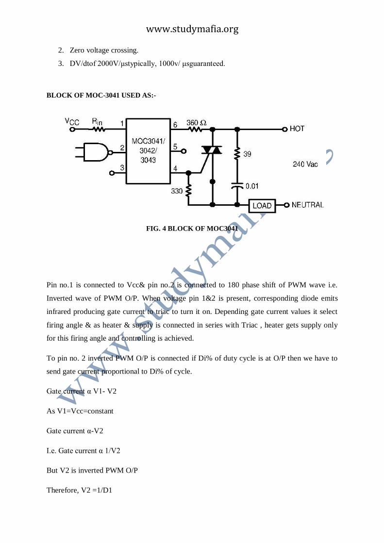
3.OPTOISOLATOR (MOC 3041):-
It is 6 –pin zero –crossing detector,optoisolatortriac driver IC. It consist of arsenide
infrared light emitting diode optically coupled to monolithic silicon detector performing
function of zero voltage crossing bilateral triac driver hence , dependingOn duty cycle of
(%D) PWM wave , it drives triac by selecting corresponding firing angle of triac.
Advantages of optoisolator are:-
1. it is electrically isolating PWM controller from high power device i.e. heater
2. due to unidirectional signal transfer to output side i.e. to PWM controller
3. it is small in size & light weight device
4.
Features:-
1. Simplified logic control of 115V power.
www.studymafia.org
2. Zero voltage crossing.
3. DV/dtof 2000V/μstypically, 1000v/ μsguaranteed.
BLOCK OF MOC-3041 USED AS:-
FIG. 4 BLOCK OF MOC3041
Pin no.1 is connected to Vcc& pin no.2 is connected to 180 phase shift of PWM wave i.e.
Inverted wave of PWM O/P. When voltage pin 1&2 is present, corresponding diode emits
infrared producing gate current to triac to turn it on. Depending gate current values it select
firing angle & as heater & supply is connected in series with Triac , heater gets supply only
for this firing angle and controlling is achieved.
To pin no. 2 inverted PWM O/P is connected if Di% of duty cycle is at O/P then we have to
send gate current proportional to Di% of cycle.
Gate current α V1- V2
As V1=Vcc=constant
Gate current α-V2
I.e. Gate current α 1/V2
But V2 is inverted PWM O/P
Therefore, V2 =1/D1

www.studymafia.org
Therefore, gate current α 1/(1/D1)
Therefore, gate current α D1
For MOC 3041 input current should not exceed to 15ma, for 100% duty cycle. But in our
circuit maximum duty cycle is
Therefore, Rin = Vc/If
=5/35
=0.2 × 10³
Therefore, Rin=200Ω
Ci capacitor is used for snubbing of Triac
4.ANALOG TO DIGITAL CONVERTER(ADC0809):-
The ADC0808, ADC0809 data acquisition component is amonolithic CMOS device with an
8-bit analog-to-digital converter,8-channel multiplexer and microprocessor compatiblecontrol
logic. The 8-bit A/D converter uses successive approximationas the conversion technique.
The converter features high impedance chopper stabilized comparator, a256R voltage divider
with analog switch tree and a successiveapproximation register. The 8-channel multiplexer
candirectly access any of 8-single-ended analog signals.
The device eliminates the need for external zero andfull-scale adjustments. Easy interfacing
to microprocessorsis provided by the latched and decoded multiplexer addressinputs and
latched TTL TRI-STATE® outputs.
Features:-
1. Easy interface to all microprocessors
2. Operatesratio metrically or with 5 VDC or analog spanAdjustedvoltage reference

www.studymafia.org
3. No zero or full-scale adjust required
4. 8-channel multiplexer with address logic
5. 0V to 5V input range with single 5V power supply
FIG. 5 PIN DIAGRAM OF ADC0809
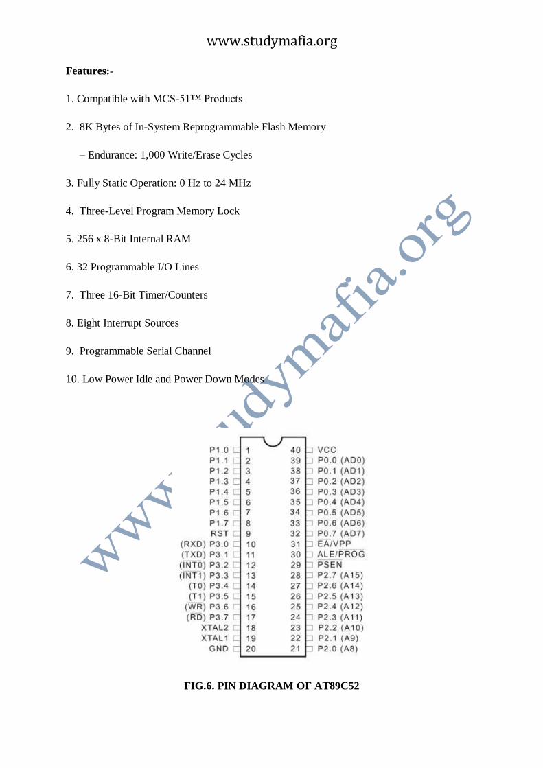
4.MICROCONTROLLER(AT89C52)
The at89c52 is a low-power, high-performance cmos 8-bit microcomputer with 8k
bytes of flash programmable and erasable read only memory (perom). The device
is manufactured using Atmel’s high density nonvolatile memory technology and is
compatible with the industry standard 80c51 and 80c52 instruction set and pin out.
The on-chip flash allows the program memory to be reprogrammed in-system or by a
conventional nonvolatile memory programmer. By combining a versatile 8-bit CPU
with flash on a monolithic chip, the Atmel at89c52 is a powerful microcomputer
which provides a highly flexible and cost effective solution to many embedded control
applications.
www.studymafia.org
Features:-
1. Compatible with MCS-51™ Products
2. 8K Bytes of In-System Reprogrammable Flash Memory
– Endurance: 1,000 Write/Erase Cycles
3. Fully Static Operation: 0 Hz to 24 MHz
4. Three-Level Program Memory Lock
5. 256 x 8-Bit Internal RAM
6. 32 Programmable I/O Lines
7. Three 16-Bit Timer/Counters
8. Eight Interrupt Sources
9. Programmable Serial Channel
10. Low Power Idle and Power Down Modes
FIG.6. PIN DIAGRAM OF AT89C52

www.studymafia.org
4.TRIAC (BT139):-
Depending on gate current supplied by MOC3041 OPTO-ISOLATOR, firing angle is
adjusted and conducting angle is set & send heater, for which heater conducts only & hence
temperature controlling is achieved.
FIG.7. SYMBOL OF TRIAC

www.studymafia.org
ALGORITHM
1. Start
2. Set the desired temperature
3. Lm35 will sense the room temperature
4. This room temperature is given to LM358. As output of LM35 is low.
5. Output of LM358 is given to ADC0809 to convert the analog signal into digital.

www.studymafia.org
6. Digital signal is then provided to at89c52 .this IC processes the data and
producing PWM waves accordingly.
7. PWM is given to moc3041 which sets the firing angle
8. According to firing angle triac starts conducting
9. We get output till the triac conducts.
10. Blub glow till the room temperature > set temperature
FLOW CHART:

www.studymafia.org
PCB DESIGN:-

www.studymafia.org
SPECIFICATIONS:-

www.studymafia.org
Devices Inputs Output
TRANSDUCER ( L M - 35) 27˚C to
38˚ C
10.0 mV/°C
AMPLIFIER ( LM – 358 ) 20mV to
100mV
0-3.8V DC
MICROCONTROLLER ( 89C52 ) 4Vto5.5V DC 1.PWM of 50Hz
2.O/P for LCD
OPTOISOLATOR ( MOC-3041 ) 1. 5V DC
2. PWM
From 89c52
Triac gate driver
Current up
To 100mA
TRIACE ( BT-139 ) 230 V AC 230V
Controlled AC
DISPLAY From 89c52 16*2 lines
Display
ADC 20mV to
100mV
from LM-358
O/P in binary
Form for 89c52
TABLE.1 . SPECIFICATIONS
COST ESTIMATION :-
COMPONENT
USED
VALUE QUANTITY RATE COST
R1 220Ω 1 0.50 0.50

www.studymafia.org
R2 330Ω 2 0.50 1.00
R2 2.2KΩ 1 0.50 0.50
R4 10KΩ 2 0.50 1.00
R5 11KΩ 1 0.50 0.50
PULL UP 10KΩ 1 8 8
C1 1000uF 1 0.50 0.50
C2 220 uF 1 0.50 0.50
C3 10uF 1 0.50 0.50
C4 0.1uF 2 0.50 1.00
C5 33nf 2 0.50 1.00
C6 0.1nF 1 3.00 3.00
Q1 BC547 1 5 5
IC1 LM-35 1 40 40
IC2 LM-358 1
IC3 89C52 1 50 50
IC4 MOC-3041 1 10 10
IC5 BT139 1 12 12
DISPLAY LCD 1 40 40
TRANSFORMER 0-9V 1 40 40
BULB 60 W 1 15 15
PCB DESIGNING - 1 600 600
CABINET 10”×8”×4” 1 150 150
SWITCHES PUSH 3 2 8
TABLE.2 . COST ESTIMATION

www.studymafia.org
CONCLUSION:-
Thus through our project we can control the temperature of any closed chamber andhence the
desired temperature can be provided to the chamber. So it can be used in any placewhich
requires a precise temperature to be set .eg. incubator , medicine storage , textile industries
etc.
we set the temperature to a desired temperature and as the room temperature in less than the
desired one , bulb connected will glow and provide the required temperature, this will last as
long as temperature of room is less then desired , after this bulb will automatically switch
off.
.

www.studymafia.org
APPLICATIONS :-
1. Warmer Controller Systems.( Controlling parameters of incubator )
2. In domestic applications like controlling room temperature and humidity.
3. As water Heating system for aquarium.
4. To control precise temperature in medicine and chemical industries.
5. In textile industries ( for silk production )
6. In air conditioning and water cooler system to make system automatic and
independent.

www.studymafia.org
FUTURE MODIFICATION :-
1. Improved temperature range.
2. Can also be used I in controlling temperature of different liquids.
3. Parameters can be operated by remote control.
4. Compact design

www.studymafia.org
BIBLIOGRAPHY:-
www.google.com
www.wikipedia.org
www.styudymafia.org
Recommended
![NFI – INDUSTRIAL AUTOMATION TRAINING ACADEMYnfiautomation.org/Six Months Industrial Automation Syllabus.pdf · [NFI – INDUSTRIAL AUTOMATION TRAINING ACADEMY] ... Motor Timing](https://img.pdfslide.net/doc/110x75/5af8aad47f8b9ad2208cd6bd/nfi-industrial-automation-training-months-industrial-automation-syllabuspdfnfi.jpg)