Revision 1
Revision 1
2
Instruction and Installation Manual
for Model
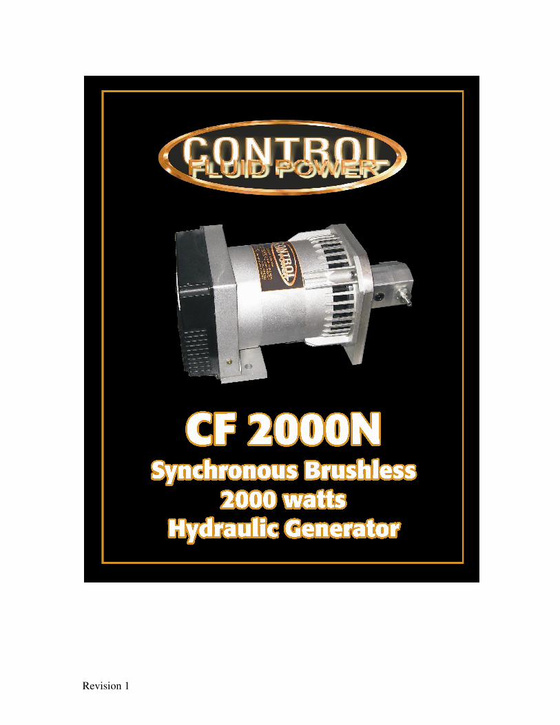
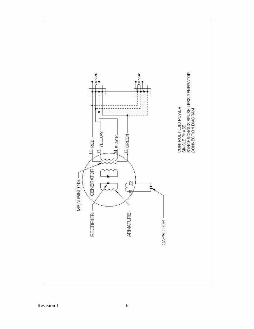
CF 2000N Synchronous Brushless
2000 watts 60 HZ
Hydraulic Generator
Revision 1
3
Specifications
Generator...........................Brushless
Voltage..............................120 or 120/240
Frequency...........................60 Hz
Output..................................2000 watts Continuous
Insulation Class ...................F
Overload Protection.............15 Amps
Thermal overload is automatic reset type
Voltage regulator ………...Inherent type
Hydraulic Motor.................Gear type
Pressure Balanced
Speed Control.....................Pressure Compensated
Flow Control By-Pass
Maximum RPM..................4000 RPM
(3600 RPM @ 60 Hz)
Shaft Size.......................... ½ inch Dia.
Port Size
Inlet..........................#10 SAE ORB
Outlet.......................#10 SAE ORB
Case Drain........................Internal
Revision 1
4
Installation Recommendations
And
Operation Requirements
Flow Rate...................................4.8-5.4 GPM
Pressure Line..............................1/2 inch
Return Line................................3/4 inch
Recommended operating oil temperature 90°-125°F
NOTE DO NOT EXCEED 150 DEGREES F.
Installation of oil cooler is advised
2500 psi open circuit system
Recommended filtration................10 micron
Hydraulic oil..................................SUS 150-200
Return oil Line should be dedicated to generator hydraulic motor
and should go directly to tank. Failure do so could cause excess
back pressure and damage motor oil seal. Note back pressure is
not to exceed 50 psi.
Note Maximum Generator Operating Temperature-
Continuous (100 F degrees ambient) is 179 degrees Fahrenheit.
If the ambient temperature is above 100°F standard, the
temperature must be reduced by the same number of degrees. This
holds the maximum allowable operating temperature constant.
Revision 1
5
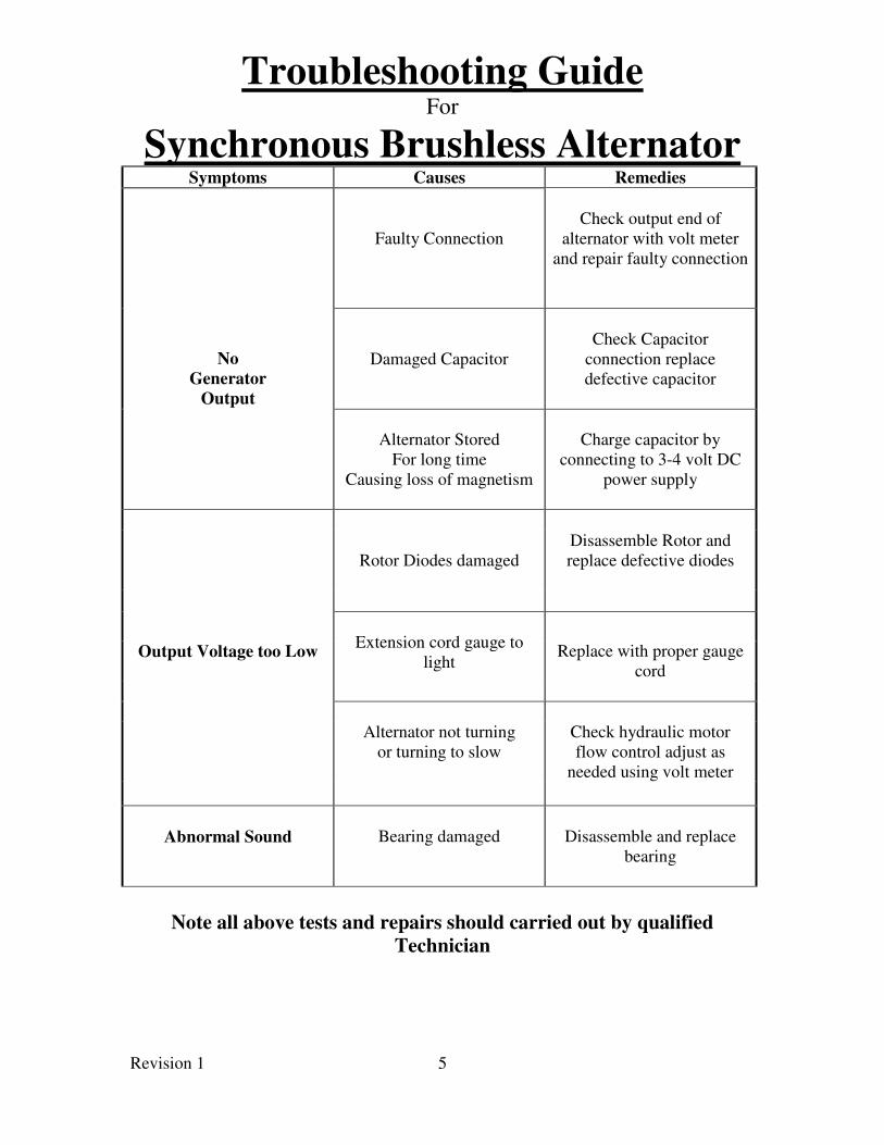
Troubleshooting Guide For
Synchronous Brushless Alternator
Symptoms Causes Remedies
No
Generator
Output
Faulty Connection
Check output end of
alternator with volt meter
and repair faulty connection
Damaged Capacitor
Check Capacitor
connection replace
defective capacitor
Alternator Stored
For long time
Causing loss of magnetism
Charge capacitor by
connecting to 3-4 volt DC
power supply
Rotor Diodes damaged
Disassemble Rotor and
replace defective diodes
Extension cord gauge to
light
Output Voltage too Low Replace with proper gauge
cord
Alternator not turning
or turning to slow
Check hydraulic motor
flow control adjust as
needed using volt meter
Abnormal Sound
Bearing damaged
Disassemble and replace
bearing
Note all above tests and repairs should carried out by qualified
Technician
Revision 1
6
Recommended