Introduction of Product
Introduction of Mobile Crusher BR580JG-1
Yasutaka Nishida
Hiroshi Yoshida
Ryoichi Togashi
A new mobile crusher series “BR580JG” has been sold that completely innovates the specification of the former BR550JG of the 50-ton class in a full model change for crushing and reuse of construction by-products produced at sites in civil engineering works and demolition works and for primary crushing at quarries and mines. The new product is overviewed and its features are introduced.
Key Words: Mobile crusher, jaw crusher, Tier3, automatic adjustment mechanism for crusher outlet clearance,
crusher protection mechanism, KOMTRAX
1. Introduction
The technique to dispose and recycle concrete waste that is generated in demolition works, as well as construction by- products that are generated in civil engineering works at work sites such as natural stones and rocks, using mobile crushers is greatly effective in lowering work costs and in solving disposal site problems and social problems including traffic congestion caused by waste carrying vehicles.
In quarries and mines, primary crushing is performed in mines and quarrying sites and crushed waste is transported to stationary plants for secondary crushing, or secondary crushing machines are also installed at mining and quarrying sites to produce products. This technique can also lower the crushed rock production cost.
This technique has been used in Europe as a routine method from early on and many manufacturers of mobile crushers are competing with each other in the market. This trend is gra-dually spreading to the world including the North America and Japan.
Since the introduction of its first-generation Galapagos model BR60 in the market in 1992, Komatsu has refined the product and expanded the product series. Komatsu decided to manufacture equipped crushers in its 30t-class BR380JG series sold in 2003 in house. The construction and functions of the crusher were completely changed. As a result, the develop-
ment concept of this series has won a high evaluation in the market and sale of the series is on a high level.
Targeting the North American and European markets especially, the high-end model BR550JG has undergone a model change, including in-house manufacture of the crusher and incorporation of product features of the same concept as those of the BR380JG in the series. The new version of the BR550JG is now sold as “BR580JG” after the model change, as outlined in the following (Photo 1).
Photo 1 Full view of BR580JG-1
2007 ② VOL. 53 NO.160 Introduction of Mobile Crusher BR580JG-1
― 1 ―

2. Objective of Development
In starting the development of BR580JG, the following implementation items were set for it incorporating functional enhancement following the development concept of BR380JG with a focus on “Safety,” “IT” and “Environment,” which are the corporate brand concepts of Komatsu (Table 1).
The configuration requirements of BR580JG and flow of crushed materials are described below.
Raw materials (concrete waste material, stones, rocks and other materials) charged into the hopper are fed into the crusher through the vibration of a grizzly feeder and are crush-ed to a size according to the outlet clearance that is set in advance and are ejected to the outside of the crusher by a belt conveyor underneath.
Sand, earth, pebbles and other materials in fed raw materials are separated by grizzly bars and are dropped onto the belt conveyor after passing through the sliding chute.
By operating the change-over plate inside the sliding chute, selection can be made whether to move out by mixing with crushed products by the belt conveyor or to eject after sepa-ration (side conveyor is selected as an option),
If reinforcements or other materials are mixed in fed raw materials, these materials are ejected to one side of the machine body by using magnetic separator (option), allowing separation from products after crushing (Fig. 1).
Table 1 Objectives of development
● A new crusher with upgraded functions is equipped.
• Reduction in downtime during jamming of foreign matter (Adoption of a crusher protection mechanism by a link mechanism with a lock cylinder)
• Easy adjustment of outlet clearance (Adoption of hydraulic adjustment mechanism)
● System to monitor machine body problems by adopting multi-function monitor
Safety, maintainability
● Easy foreign matter removal work ● Fully-automatic outlet clearance adjustment system is equipped. ● Operation from the ground through a centralized operation switch panel
IT, operability
● Adoption of one-touch start switch ● Compliance with Tier3 exhaust gas regulation: Komatsu SAA6D125E-5 engine is equipped. Environment ● Reinforcement of anti-dust measures
Feed hopper
Feeding materials
Grizzly bars
Magnetic separator (Option) Belt conveyor Jaw crusher
Grizzly feeder
Vibration generator
Selector door Chute
Fixed teeth Movable teeth Swing jaw
Fig. 1 Machine configuration and flow of crushed materials
2007 ② VOL. 53 NO.160 Introduction of Mobile Crusher BR580JG-1
― 2 ―

3. Accomplishment Means
Based on the foregoing development objectives, the selling points and accomplishment means of BR580JG were set as follows.
2007 ② VOL. 53 NO.160 Introduction of Mobil
― 3 ―
e Crusher BR580JG-1
3.1 Safety and maintainability
1) New crusher with upgraded functions is equipped. Operation sites, ambient environments, fed raw materials
and other factors are diversifying for mobile crushers operating in the field.
For this reason, the following two works have been necessi-tated, increasing the man-hours for conventional machines.
i) Work to adjust crusher outlet clearance
Before starting crushing work, the clearance of the crusher outlet needs to be adjusted to a suitable size according to the grain size after crushing.
On the other hand, the tooth plate is worn as more work is performed and the outlet clearance as mentioned above be-comes larger than the initially adjusted size, requiring re-adjustment.
BR550JG required adjustment work by the following pro-cedures.
(1) A gauge for measurement of the outlet clearance is inserted into the crushing chamber from above the crusher to measure the outlet clearance A-1 at present and to determine any difference with the target clear-ance.
(2) The cylinder is operated to slide the toggle block and to open the space to mount and dismount the clearance adjustment plate.
(3) Referring to the relational equation between the outlet clearance and clearance adjustment plate thickness (Fig. 3), a combination of the thickness of clearance plates and the number of plates is selected and is inserted (or is removed) so that the required plate thickness ∆T will be obtained.
(4) Operating the cylinder, the toggle block is slid to have it contact tightly with the clearance adjustment plate.
(5) Using an outlet clearance measurement gauge, a check is made to see if the targeted clearance is achieved (Figs. 2 and 3).
ii) Operation shutdown and restoration work if foreign matter
is mixed and jammed If a metal lump or a similar material is mixed in raw
materials and fed to the crusher by error, such material is tena-ciously jammed in the crusher teeth and the crusher stops its operation suddenly.
In this case, the crusher components may get damaged. In the conventional machines, the toggle plate would buckle to prevent crusher from being damaged, especially on main
bearings and frame (Fig. 4).
Gauge for measuring outlet clearance Clearance adjustment plate
Cylinder
T: Thickness of shim plates
Fig. 2 Outlet clearance adjustment procedure - BR550JG
Fixed jaw plate
Movable jaw plate
Toggle block
Movable jaw plate
Fixed jaw plate A: Outlet clearance
Z
Z
(Clearance, max.)
Outlet clearance adjustment rangeOutlet
clearance A
(Clearance, min.)(Minimum)
Thickness of shim plates
Fig. 3 Relationship between outlet clearance and shim plates - BR550JG -
Fed material
Toggle plate Foreign matter
Fig. 4 Jamming of foreign matter - BR550JG -

If this happens, the inside of the crushing chamber of the crusher will be filled with fed materials and will be blocked. This filled material must first be removed to resume crusher operation and this tenaciously jammed metal lump is removed by melting and cutting it. Then the buckled toggle plate must be changed with a new one. A long time (about one day) is required and tough work is required to fully restore operation.
To solve these two problems, the structure of the equipped crusher was greatly reviewed to upgrade the ease of mainte-nance and restoration work, as well as safety.
2007 e Crusher BR580JG-1
4 ―
② VOL. 53 NO.160 Introduction of Mobil
―
i) Easy adjustment of outlet clearance (Automatic adjustment mechanism)
The structure of the equipped crusher is shown in Fig. 5. The upper side of the swing jaw is supported by the main
shaft (eccentric shaft) and the lower side, by the toggle plate. A rotary link and special lock cylinder are adopted as members to support the toggle plate. By operating the cylinder through the monitor panel, adjustment of tooth tip clearances can be made.
A function has been added by installing a potentiosensor inside the crusher to detect the rotating angle of the link men-tioned above as a value of the outlet clearance, to calculate the sensor output signal and to numerically display the current output clearance on the monitor panel.
Because of this function, frequent maintenance work such as mounting and dismounting the clearance adjustment shims
became unnecessary, allowing automatic clearance adjustment by directly inputting clearance values as targets onto the moni-tor panel.
In the clearance adjustment process, the movable teeth are pushed onto fixed teeth to reduce the clearance to 0mm, to make a 0-point correction in the system.
This function corrects deviations in displayed values caused by wear of teeth plates and other causes.
Thus, the work to measure tooth tip clearances that was necessary with conventional machines has become unnecessary (Fig. 6).
Potentiosensor
Lock cylinders
Link Toggle plate
Movable jaw plate
Swing jaw Fixed jaw plate
Movable jaw plate
Fixed jaw plate A Outlet clearance
ZZ (Outlet clearance)
Fig. 5 Cross section of crusher
( Electric signal) Potentiosensor Cont-
roller
EPC valve
Control valve [Operation section] [Clearance display]
Multiple-function monitor
Link
Toggle plate Swing jaw
Operation flow [Example] Setting clearance from 100mm to 130mm 1. Initial status → 2. Contact → 3. Completion
Clearance A = 100 (±α) → Monitor display 100
Cylinder <Expand> Clearance
<Contract> Operation
Clearance A = 0 → 0-point correction → Monitor display 0
Cylinder <Contract>Clearance <Expand> Operation
Clearance A = 130 → Monitor display 130
(Movable jaw plate)
(Movable jaw plate)
(Movable jaw plate)
(Fixed jaw plate)
(Fixed jaw plate)
(Fixed jaw plate)
Fig. 6 System diagram of automatic outlet clearance adjustment mechanism

ii) Easy restora ign matter
T ed above has a different str
the cy
tion work during jamming of fore(Crusher protection mechanism) he special lock cylinder mention
ucture and functions compared to the normal hydraulic cylinder and the cylinder tube and piston have an interference fit structure. They are normally tenaciously locked to disable expansion and contract even if an external force is applied.
On the other hand, when the lock cylinder is operated, linder tube is expanded by pressurizing oil in unlock port to
expand and retract as in the normal cylinder (Fig. 7).
Fig. 7 Structure of lock cylinders
uring normal operation, the lock cylinder is locked and ou
multiplying the load during cr
a metal lump or other object is fed by error and is jammed te
Dtlet clearance is adjusted by actuating the lock cylinder in the
foregoing operation procedures. The locking force is set by ushing by a preset safety factor and the cylinder does not ex-
pand or contract by an external force and the tooth tip clear-ance does not vary.
If
naciously in tooth tips, suddenly stopping crusher operation, the reaction from the movable teeth to the cylinder will become an anomalous load greatly surpassing the set load mentioned above, far exceeding the cylinder lock force.
For this reason, the cylinder contracts by reaction force and the movable teeth move from Position (1) to Position (2) in Fig. 8 to prevent damage to the frame, bearing, shaft or other components.
In restoration work, the cylinder is operated and the movable teeth are moved from Position (2) to Position (3) in Fig. 8, to further expand the tooth tip clearance to release the jamming of the foreign matter. The foreign matter is then dropped onto the crusher and is removed onto the conveyer.
The fed raw material filled to the capacity on the foreign matter can continually be crushed and ejected, allowing resumption of operation (Fig. 8).
Lock cylindersFed material Port on bottom side
Cylinder tube
When locked (
Piston
Port on head side
Cylinder oper
Pressurizing
Unlocked
der fixed (During sh or travel)
nsion and contraction
Interference fit) ation
(3)
(2)
(1)Foreign matterUnlock port
Cylin Cylinder expa(During clutdown, work earance adjustment) (3) After removal of foreign matter Ejected
(2) Release of jammed foreign matter (1) During crushing (Foreign matter is jammed)
Fig. 8 Operation when foreign matter is jammed
2) Easy removal of jammed foreign matter During crushing of concrete waste, reinforcements mixed in
concrete waste sometimes pass the crusher and remain on the conveyer underneath the crusher to block the conveyor move-ment.
If this happens, operation is temporarily shut down, the ejection chute under the crusher is removed, blocked reinforce-ments and other foreign matter are removed through the opening and the area is cleaned.
To simplify this work, the carrier roller is eliminated and wear plates are provided, to lower the height of the track shoe and to increase the dimensions of the opening for easy access-ing (Fig. 9).
2007 ② VOL. 53 NO.160 Introduction of Mobile Crusher BR580JG-1
― 5 ―

Fig. 9 Op
3) Anti-slip
Anti-slip provided in during checand durabili
4) Centralized greasing Grease nipples in the bearing part in the crusher operation
section and in the pin bush part totaling 12 are put together in one place, to facilitate greasing during checks and maintenance work.
eDimensions of opening (mm)
BR580JG BR550JG
B (Breadth) 1500 650
H (Height) 400 200
2007 ② VO
Wear plates
ening for mainte
ping sheets similar tplaces where tks and maintety of anti-slip s
Fig.
L. 53 NO.160
Track sho
nance and cleaning under the crusher
o emery paper and small bumps are he operator climbs onto the crusher nance work, to enhance the safety heets (Fig. 10).
10 Anti-slip
Photo 2 Centralized greasing
3.2 IT
1) Centralized operation panel A centralized operation panel incorporating the multiple-
function monitor mentioned above and switches is installed in the lower part of the machine body to facilitate machine ope-ration and monitoring from the ground (Fig. 11).
Small bump Anti-slip sheet of emery paper type
[Cross section of bump]
(*) One-touch start switch
Operation switches for normal operation
• Engine operation • Horning • All work equipment start/stop*• Emergency stop
Multiple-function monitor • Adjustment of work equipment
speed and other items • Monitor display • Failure diagnosis
Operation switches for individual work equipment (Normally, the all work equipment start/stop switch* is operated)
Fig. 11 Centralized operation panel
Introduction of Mobile Crusher BR580JG-1
― 6 ―

2) Operation monitoring system by multiple-function monitor A multiple-function monitor is equipped inside the operation
panel and display of the crusher outlet clearance mentioned above and an adjustment operation function have been added. The functions to display machine operation status, as well as problem location and status in the case of an anomaly, have been reinforced.
One example of monitor display is illustrated in Fig. 12.
Fig. 12 Example of multiple-function monitor
3) Adoption of one-touch start function
A one-touch start switch is installed to start and stop the equipped work equipment (feeder, crusher, conveyor, side con-veyor and magnetic separator) by touching one button switch, to free the operator from complicated operations (Fig. 11).
4) Radio controller (Option) The radio controller as an option can let the mobile crusher
travel and can operate the work equipment (start and stop of the crusher and feeder).
A power key switch on the transmitter and radio controller/ panel operation selection switch on the centralized operation panel on the machine body side are provided to prevent abrupt and unexpected operation. A rotating lamp is installed above the machine body to indicate that the vehicle is radio controlled (Fig. 13). : Work status indicator lamp
(Lit red in case of problem) Work mode
Indication of work equipment operation status, and so on
Indicator lamp for radio controller communication status
Display of engine system status
[In normal operation] - Work mode -
Problem indication (Error code)
[Rotating lamp]
[Operations by radio controller]• Horn • One-touch start • One-touch stop • Crusher start • Crusher stop • Feeder start • Feeder stop • Travel • All stop (Engine stopped)
[In the case of anomaly]
[Transmitter]
Radio controlleroperation mode
Panel operation mode
[Radio controller/panel operation selection switch]
Fig. 13 Radio controller
2007 ② VOL. 53 NO.160 Introduction of Mobile Crusher BR580JG-1
― 7 ―

3.3 Environment 1) Engine meeting Tier3 exhaust gas regulation
The Komatsu SAA6D125E-5 engine that accomplishes low NOx and PM emissions thanks to the electronically controlled common rail injection system and cooled EGR system is equipped (Table 2).
Table 2 Comparison of engines
BR580JG-1 BR550JG-1 Engine name — SAA6D125E-5 SAA6D125E-2Displacement ℓ 11.04 ← Rated output KW/rpm 257/1,900 228/1,950
Engine control —
Electronically controlled
(Common rail injection)
Electronically controlled (Governor
motor) Additional emission system — EGR Not provided
Aftercooler type — Air cooled Air cooled
2) Control of dust
A sprinkler nozzle is installed above the crusher as a standard specification to control dust that is generated in the crushing of rocks and stones during crusher operation. As options, sprinkler nozzles are prepared under the crusher and at the conveyer tip (Fig. 14).
As an option, a sprinkler tank and pump can be installed for convenience in locations where tap water cannot be supplied at all times (Fig. 15).
Pump assembly Tank
Fig. 15 Sprinkler tank and pump
Tube with nozzle Tube with nozzle
Tube with nozzleSprinkler nozzle under crusher (Option)
Sprinkler nozzle at tip of conveyor (Option)
Sprinkler nozzle above crusher
Fig. 14 Sprinkler nozzles
2007 ② VOL. 53 NO.160 Introduction of Mobile Crusher BR580JG-1
― 8 ―
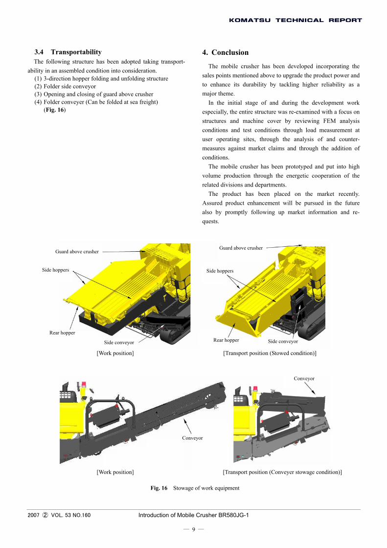
3.4 Transportability The following structure has been adopted taking transport-
ability in an assembled condition into consideration. (1) 3-direction hopper folding and unfolding structure (2) Folder side conveyor (3) Opening and closing of guard above crusher (4) Folder conveyer (Can be folded at sea freight)
(Fig. 16)
4. Conclusion
The mobile crusher has been developed incorporating the sales points mentioned above to upgrade the product power and to enhance its durability by tackling higher reliability as a major theme.
In the initial stage of and during the development work especially, the entire structure was re-examined with a focus on structures and machine cover by reviewing FEM analysis conditions and test conditions through load measurement at user operating sites, through the analysis of and counter-measures against market claims and through the addition of conditions.
The mobile crusher has been prototyped and put into high volume production through the energetic cooperation of the related divisions and departments.
The product has been placed on the market recently. Assured product enhancement will be pursued in the future also by promptly following up market information and re-quests.
Guard above crusher Guard above crusher
Side hoppers Side hoppers
Rear hopper Rear hopper Side conveyor Side conveyor
[Work position] [Transport position (Stowed condition)]
Conveyor
Conveyor
[Work position] [Transport position (Conveyer stowage condition)]
Fig. 16 Stowage of work equipment
2007 ② VOL. 53 NO.160 Introduction of Mobile Crusher BR580JG-1
― 9 ―

Introduction of the writer
Yasutaka Nishida Entered Komatsu in 1986. Currently assigned to Construction Equipment Technical Center 1, Development Division.
Hiroshi Yoshida Entered Komatsu in 1987. Currently assigned to Construction Equipment Technical Center 1, Development Division.
Ryoichi Togashi Entered Komatsu in 1993. Currently assigned to Planning & Administration Department, Development Division.
[A few words from the writer] Since the introduction of Komatsu’s first-generation Galapagos
model to the market in 1992, the in-house recycling technique has become a routine practice at demolition and civil engineering work sites in Japan. On many occasions, Komatsu’s Galapagos crush-ers have been sighted at work sites.
Since then, the machines have continued to advance while the environment surrounding us has experienced many changes. Recalling the days before and immediately after starting the development work, it is indeed memorable that a crusher with a new, unique mechanism could be developed and manufactured in house.
The BR580JG is a large mobile crusher of the 50-ton class, for which the market demand is highest in the overseas market. It is hoped that more of the BR580JG will be sold and will serve the users well.
2007 ② VOL. 53 NO.160 Introduction of Mobile Crusher BR580JG-1
― 10 ―
Recommended