HALFA N I S O 9 0 0 1 C O M P A N Y
FULL
146-1923
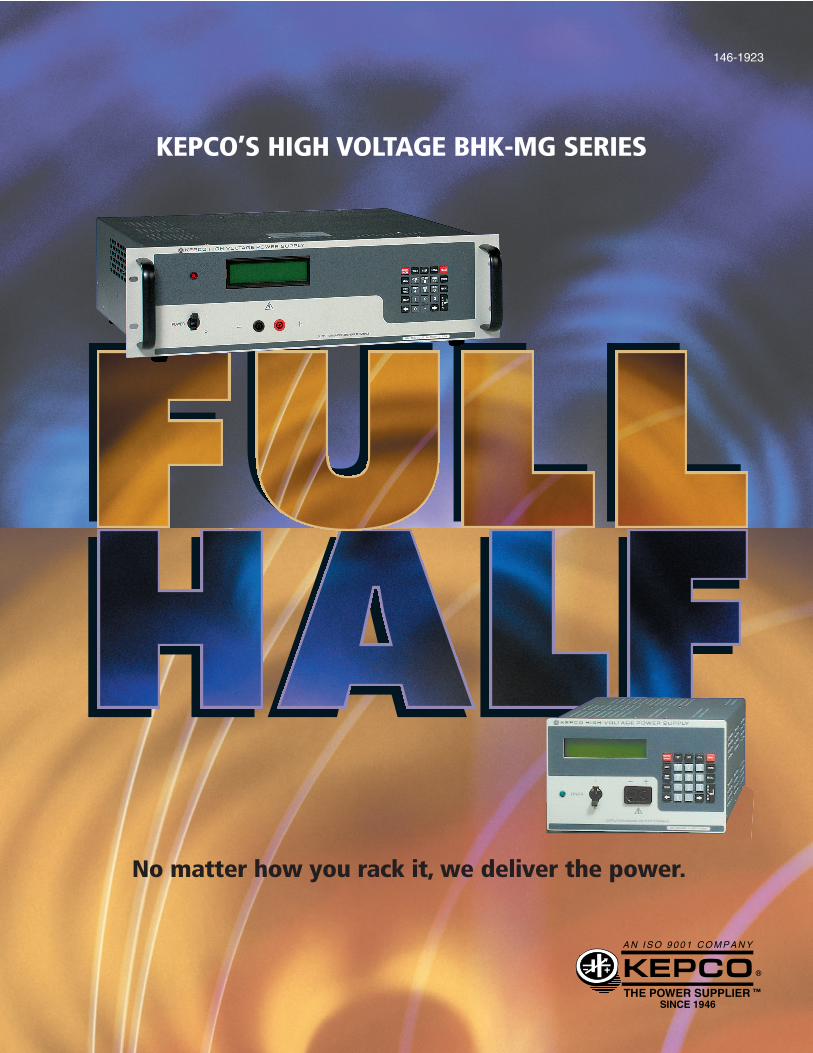
No matter how you rack it, we deliver the power.
KEPCO’S HIGH VOLTAGE BHK-MG SERIES

BHK-MG MODEL TABLE
MAXIMUM OUTPUT IMPEDANCE OUTPUT IMPEDANCEd-c OUTPUT OUTPUT SLOW MODE STRAPPING FAST MODE STRAPPING
MODEL RANGE POWER VOLTAGE MODE CURRENT MODE VOLTAGE MODE CURRENT MODEVOLTS mA (1) (WATTS) SERIES R SERIES L SHUNT R SHUNT C SERIES R SERIES L SHUNT R SHUNT C
40 WATT HALF RACK
BHK 300-130MG 0-300 0-130 39 0.115Ω 1.5mH 15.4MΩ 6.6µF 0.115Ω 2mH 15.4MΩ 9nF
BHK 500-80MG 0-500 0-80 40 0.313Ω 2.5mH 41.7MΩ 3µF 0.313Ω 3.6mH 41.7MΩ 8nF
BHK 1000-40MG 0-1000 0-40 40 1.25Ω 5mH 166MΩ .94µF 1.25Ω 6mH 166MΩ 2nF
BHK 2000-20MG 0-2000 0-20 40 5Ω 32mH 666.7MΩ 0.2µF 5Ω 35mH 666.7MΩ 1nF
200 WATT FULL RACK
BHK 300-0.6MG 0-300 0-600 180 0.025Ω 1.2mH 3.33MΩ 20µF 0.025Ω 2mH 3.33MΩ .013µF
0-60 18 33.3MΩ 33.3MΩ .008µF
BHK 500-0.4MG 0-500 0-400 200 0.0625Ω 2mH 8.3MΩ 10µF 0.0625Ω 3.6mH 8.3MΩ .012µF
0-40 20 83MΩ 83MΩ .007µF
BHK 1000-0.2MG 0-1000 0-200 200 0.25Ω 4mH 33MΩ 4µF 0.25Ω 6mH 33MΩ .005µF
0-20 20 333MΩ 333MΩ .003µF
BHK 2000-0.1MG 0-2000 0-100 200 1Ω 30mH 133MΩ 2µF 1Ω 35mH 133MΩ .002µF
0-10 20 1333MΩ 1333MΩ .001µF
BHK-MG models are designed forbench or rack mount use with bothfront and rear output terminals. Twooperating modes are available: conventionally filtered (slow mode) foruse as a fixed or slowly varied voltagesource. In this mode, the outputcapacitor provides excellent energystorage to support transient loads. Afast mode is also available. In fast mode,the output capacitor is disconnected andthe power supply depends on its fast-responding feedback loop to suppressripple and noise. Fast mode is idealfor operation as a current source or as
a rapidly programmed voltage sourcewhere the energy storage of a conven-tional output capacitor would inhibitthe output voltage’s agility.
Control is either analog or digital.Analog control is based on the idea ofan operational amplifier in which thepower supply output is programmablefrom zero to maximum with a 0-10Vsignal. Digital control is IEEE 488.2using a built-in interface that supports SCPI. Resolution is 12 bitsand controls both voltage and current.A front panel keypad provides local
control. Both digital control (local orremote) and analog control can beinputted simultaneously.
The display is an alphanumeric two-line LCD which provides bothsetting values and actual voltage andcurrent readings.
BHK-MG use a solid state FET-based high voltage output stage.
BHK-MG comply with EN61010-1safety standard for measurementcontrol and laboratory use equipmentand carry the CE mark.
(1) The full rack BHK-MG have 10:1 current ranging. By command selection from the keypad or GPIB, the full 12-bit control resolution is available across 0-10% of the current rating.
Data subject to change without notice. ©2003 KEPCO, INC. Litho in USA

SPECIFICATIONS RATING/DESCRIPTION CONDITION
BHK-MG GENERAL (ENVIRONMENTAL) SPECIFICATIONS
SPECIFICATIONS RATING/DESCRIPTION CONDITION
Temperature Operating 0° to +50°C
Storage -20° to +75°CHumidity 0 to 95% RH Non condensing
operating & storage
Shock 20g, 11msec ±50% Non operating, 3-axeshalf sine 3 shocks each axis
Vibration 5-10Hz 10mm Non operating, 3-axesdouble amplitude 1 hour each axis
Cooling Built-in fan, exhaust air to rear
Remote Error Sensing Provisions for 4-terminal (Kelvin)(Default state is local sensing) connections to load
BHK-MG PHYSICAL CHARACTERISTICS
Dimensions
Weight
a-c sourceconnections
d-c outputterminals
Control
Digital display front panel
Output display
English
Metric
English
Metric
Front
Rear
Front
Rear
Local
Remote
5.22˝ x 8.35˝ x 15.9˝
133 x 212 x 404mm
26 lbs.
12 Kg
5.22˝ x 19˝ x 15˝
133 x 482.6 x 381mm
45 lbs.
20 Kg
Circuit breaker, 2-pole
Detachable IEC 3-wire type connectorinterlock switch (200W only)
Jacks (2)
Terminal blocks (11 positions)
Voltage, current, mode, status, menu, program 2 x 16 character alphanumeric LCD, LED backlight
Interlock switch (200W)/proximity detector (40W) protects rear connections
±Output
±Output, ±sense, ground,grounding network, internal capacitor (-)
Excludes handles, feet and connectors
Unpacked
Digital control using front panel keypad
Digital control using rear panel IEEE 488 bus (24 pin female connector).Analog control using two rear panel terminal strips (10 positions each) for voltage and current.
Output voltage is displayed with two decimals for 300 and 500V models and one decimal for 1000 and2000V models. Output current for 200W (high current scale) and 40W (300V model) is displayed with two decimals. 200W (low current scale) and all other 40W models are displayed with three decimals.
40W 200W
Kepco’s BHK-MG are high voltagelinear voltage-current stabilizers offeredin two sizes: a 40 watt half-rack designand a 200 watt full-rack power supply.Outputs range from 0-300 volts to0-2000 volts. Both digital and analogprogramming control is featured.
BHK-MG are CE marked per the LowVoltage Directive (LVD), EN61010-1and the EMC Directives.
FEATURES
• Two sizes: half-rack 40 watts, full-rack 200 watts.
• FET output stage.
• Conventional filtering or fast response.
• Fast analog programming mode.
• Rapid recovery current mode in fast mode.
• Local control from panel-mounted keypad.
• Built-in GPIB, IEEE 488.2, 12 bits.
• Support for SCPI language.
• 2-line 16 character LCD display.
• Full read back of voltage and current on the bus.
• Increased resolution and accuracy (x10) for reading small current.
• Versatile output on/off port (40W only).
• Extensive protection circuitry.
A N I S O 9 0 0 1 C O M P A N Y
KEPCO, INC. • 131-38 Sanford Avenue • Flushing, NY 11352 USA • Tel: (718) 461-7000 Fax: (718) 767-1102 • Email: [email protected] • www.kepcopower.com/bhkmg.htm
115/230V a-c
105-125/210-250V a-c
50/60Hz
47-63Hz
1350V a-c/1 min.
1950V d-c/1 min.
2250V d-c/1 min.
2800V d-c/1 min.
100 mohms max.
BHK-MG INPUT CHARACTERISTICS
a-c Voltage
Frequency
Current
Withstand Voltage
Chassis Connection to Ground Resistance
Leakage Current
Single phase, switch selectable
At nominal output power
Between shorted inputsand chassis
Between shorted outputs and chassis
Between ground inputconnection and chassis @ 30A
nominal
range
nominal
range
115V a-c
230V a-c
(All models)
300V models
500V models
1000V models
2000V models
SPECIFICATIONS RATING/DESCRIPTION40W 200W
CONDITION
25 µA rms/100 µA p-p, for 115V a-c input voltage(chassis to earth-ground)
1A
0.6A
<4.0A a-c
<2.1A a-c

SPECIFICATIONS RATING/DESCRIPTION CONDITION
Type of Stabilizer Linear/automatic crossover Voltage/CurrentAdjustment Voltage 0 to 100% Eo max Analog or digital, 12 bitRange
Current 0 to 100% Io max Use menu program (Source) 0 to 10% Io max to change
(200W models only) current scale
Current 50% Io max (200W) Fixed value(Sink) 100% Io max (40W) not calibrated
Programming Voltage 0.025% Eo max Current measurementResolution Current 0.025% Io max
requires acalibrated shunt
Programming Voltage <0.025% Eo maxAccuracy Current <0.05% Io max Both current scales
(200W models)
Data Readback Voltage <0.05% Eo maxAccuracy Current <0.05% Io max Both current scales
(200W models)
Source Effect Voltage <0.001% Eo max Input voltageCurrent <0.002% Io max 105-125/210-250V a-c
Load Effect Voltage <0.005% Eo max no load-full loadCurrent <0.015% Io max short-full load
Temperature Voltage <0.01% Eo max Per °CEffect Current <0.02% Io max (0 to 50°C)
Time Effect Voltage <0.01% Eo max 0.5-8.5 hoursCurrent <0.02% Io max (5)
Ripple/Noise Fast Mode 0.002% /0.02% Eo max See Note 6
Slow Mode 0.001% /0.01% Eo max
Programming Rise/ Voltage 180 µsecFall Time (Fast mode) Current 200 µsec
See Note 1
Transient Voltage Fast Mode 1 msecRecovery
Slow Mode 15 msec See Note 2Time forLoad Change
Current Fast Mode 500 µsec
Small Signal Voltage 2.5KHz See Note 33dB Bandwidth Current 2.3KHz See Note 4
Slew Rate of the Voltage >0.015 x Eo max V/µsecOutput Voltage
>0.03 x Eo max V/µsec High range(Fast mode) Current
Overshoot None Turn ON/OFFRemote Sensing Range 0.5V d-c per lead
300V modelsd-c500V models
1KV d-c or p-p plus
Between eachIsolation
1000V modelsmax. output voltage
output terminalVoltage
2000V models 0.5KV d-c or p-p plus and chassismax. output voltage
Enable/Disable Local Front panel keypadSee Note 7Output Power Remote IEEE 488 (GPIB) bus
Output Display Local 2 x 16 character alphanumeric backlit LCD
Series Connection Automatic or master-slave For slave unit, use operation, limited by the analog programmingd-c isolation limit voltage only
Parallel Connection Automatic or master-slave For slave unit, use operation analog programming
only
Note 1: Load = Eo max / Io max. Vout between 0-Eomax.The programming time is measured between 10% and 90% of Eo max or Io max.
Note 2: Voltage mode, load switched from open circuit to Io max. at Eo = 200V. Currentmode, load switched from short circuit to 200V at Io max.
Note 3: For maximum load (Eo max / Io max) with a d-c bias of 200V set by the keypad and an analog input sinusoid = 0.2V r ms measured at the analog input terminals.
Note 4: For maximum load (Eo max / Io max) with a d-c current bias = 200 x Io max / Eomax set by the keypad and an analog input sinusoid = 0.2V r ms measured at theanalog input terminals.
Note 5: 0.05% for BHK 300-0.6MG.
Note 6: With minus terminal grounded, common mode current does not flow through eitherthe load or the current sensing resistor.
Note 7: 200W models: Acts on digital programming only; 40W models: Versatile output on/offport (digital/relay contacts) acts on both analog and digital programming.
SIDE VIEW
FRONT VIEW
BHK-MG HALF-RACK MODELS
BHK-MG FULL-RACK MODELS
TOP VIEW
SIDE VIEW
REAR VIEW
8.120(206.25)
4.860(123.44)
.250(6.35)
.112 (2.84)
17 (431.80)15.90 (403.86)
.250 (6.35)
TOP VIEW
REAR VIEW
Rear Front
Rear Front
OUTLINE DIMENSIONAL DRAWINGSFractional dimensions in light face type are in inches, dimensions in bold face type are in millimeters.
Tolerance: ± 1/64" (0.4) between mounting holes, ± 1/32" (0.8) other dimensions
FRONT VIEW
5.218(132.54)
8.344 (211.94)
A N I S O 9 0 0 1 C O M P A N Y
KEPCO, INC. • 131-38 Sanford Avenue • Flushing, NY 11352 USA • Tel: (718) 461-7000 Fax: (718) 767-1102 • Email: [email protected] • www.kepcopower.com/bhkmg.htm
BHK-MG OUTPUT CHARACTERISTICS

Available from
Power sources and test instrumentation solutionsCaltest have been providing power sources and test instrumentation solutions for over 20 years and are proud to represent a number of industry leading manufacturers.
As well as supplying world class power sources and test instrumentation Caltest also has a service centre and UKAS calibration laboratory.
Caltest Instruments Ltd 4 Riverside Business Centre Walnut Tree Close Guildford Surrey GU1 4UG United Kingdom
NEED HELP?
CALL US: 01483 302 700
or visit our website for more details
Tel: +44 (0) 1483 302 700
Fax: +44 (0) 1483 300 562
www.caltest.co.uk
Sales • Rentals • Service • UKAS Calibration
Recommended