Table of Contents
Introduction ......................................................................................................................... 1
Purpose of this guide .................................................................................................... 1
Cumbria County Council’s Approach – a Sense of Place ............................................... 3
Place and movement..................................................................................................... 3
Managing the process ................................................................................................... 5
Provision of Pre-application Advice................................................................................ 6
Information required ...................................................................................................... 6
Highway adoption process ............................................................................................. 7
Works within existing highway boundary ........................................................................ 7
Boundaries of adopted highways ................................................................................... 7
Health and safety (Construction Design and Management Regulations) ........................ 8
Road safety audit............................................................................................................ 8
Consideration of risk ...................................................................................................... 9
Adoption and use of open spaces .................................................................................. 9
Part 1 New Residential Development .............................................................................. 10
Chapter A. Road hierarchy ............................................................................................... 11
Permeability ................................................................................................................. 11
Types of New Residential Highway .............................................................................. 13
Footpaths & Cycle Tracks ............................................................................................ 15
Shared surface streets ................................................................................................. 15
Shared private access & Courtyards ............................................................................ 16
One-way streets ........................................................................................................... 16
Chapter B. Visibility .......................................................................................................... 17
Important factors affecting visibility............................................................................... 18
Existing roads with actual 85th percentile recorded speed data .................................... 20
Existing roads with unknown 85th percentile speeds..................................................... 21
Applying gradients ....................................................................................................... 22
Cycleways & shared use facilities ................................................................................ 23
Visibility at a junction .................................................................................................... 24
Visibility through a bend ............................................................................................... 24
Barriers to visibility at junctions .................................................................................... 25
Visibility at private accesses ........................................................................................ 25
Junction spacing .......................................................................................................... 26
Considering large vehicles ........................................................................................... 26
Chapter C. Carriageway widths........................................................................................ 27
Future proofing ............................................................................................................ 27
Typical vehicle widths .................................................................................................. 28
Typical carriageway widths .......................................................................................... 28
Roads .......................................................................................................................... 30
Access by emergency services .................................................................................... 32
Carriageway width on a bend ....................................................................................... 33
Chapter D. Junctions & radii ............................................................................................ 34
Benefits of using minimum radii ................................................................................... 36
Overrun areas .............................................................................................................. 37
Chapter E. Turning areas.................................................................................................. 38
Turning area layouts .................................................................................................... 39
Refuse vehicle requirements ........................................................................................ 40
Chapter F. Speed management ........................................................................................ 41
Horizontal features ....................................................................................................... 45
Vertical features ........................................................................................................... 45
Psychological ............................................................................................................... 46
Reducing visibility ........................................................................................................ 46
Chapter G. Gradients ........................................................................................................ 48
Dwell areas between roads .......................................................................................... 49
Carriageway widths with significant gradients .............................................................. 49
Choice of surface material ........................................................................................... 49
Surface water ............................................................................................................... 50
Chapter H. Vertical clearance ........................................................................................... 51
Pedestrians and cyclists ............................................................................................... 51
Vehicles ....................................................................................................................... 51
Chapter I. Signs & markings ............................................................................................ 52
Signs ............................................................................................................................ 52
Markings ...................................................................................................................... 53
Chapter J. Parking ............................................................................................................ 54
Importance of ‘Good’ design ........................................................................................ 56
Resident parking .......................................................................................................... 56
Visitor parking .............................................................................................................. 57
Parking bays ................................................................................................................ 58
Courtyard parking ........................................................................................................ 59
Traffic Regulation Orders and parking enforcement ..................................................... 59
Chapter K. Utility services ................................................................................................ 61
Maintenance issues ..................................................................................................... 61
Planting ........................................................................................................................ 61
Depths and lateral positions ......................................................................................... 61
Chapter L. Lighting ........................................................................................................... 63
Locating the lighting ..................................................................................................... 63
Safety .......................................................................................................................... 64
Chapter M. Landscaping .................................................................................................. 65
Retention of existing landscape features ...................................................................... 66
Carriageway proximity.................................................................................................. 66
Gateways ..................................................................................................................... 68
Adoptability of landscaping features by the Highway Authority ..................................... 68
Species selection ......................................................................................................... 68
Chapter N. Sustainable Drainage Systems (SuDS)......................................................... 69
Figure S1: An example of a swale in a development Drainage Strategy .................... 69
Sustainable Drainage Systems (SuDS) ........................................................................ 70
The Management Train ................................................................................................ 71
Design Principles ......................................................................................................... 71
Runoff Destinations ...................................................................................................... 71
Flood Risk from the Proposed Development ........................................................... 71
Peak Flow Control ........................................................................................................ 72
Volume Control ............................................................................................................ 72
Pollution Control........................................................................................................... 72
Designing for Exceedance ........................................................................................... 72
Highway Drainage ........................................................................................................ 73
Climate Change ........................................................................................................... 73
Construction ................................................................................................................. 73
Maintenance Requirements ......................................................................................... 73
SuDS Components ...................................................................................................... 74
Part 2 Commercial Development
Chapter A. Road hierarchy ............................................................................................... 77
Footways ..................................................................................................................... 77
Cycling ......................................................................................................................... 78
Shared Surfaces .......................................................................................................... 79
Chapter B. Visibility .......................................................................................................... 80
Chapter C. Carriageway widths........................................................................................ 82
Additional width requirements ...................................................................................... 82
Over size loads ............................................................................................................ 83
Chapter D. Junctions and Radii ....................................................................................... 84
Junction spacing .......................................................................................................... 85
Junction control treatments .......................................................................................... 85
Radii ............................................................................................................................ 86
Chapter E. Turning areas.................................................................................................. 87
Vertical measures ........................................................................................................ 88
Horizontal measures .................................................................................................... 88
Psychological measures .............................................................................................. 89
Chapter F. Gradients ......................................................................................................... 90
Chapter G. Vertical clearance .......................................................................................... 90
Chapter H. Signs & markings ........................................................................................... 91
Development Boundary Signage .................................................................................. 91
Development layout signage ........................................................................................ 92
Unofficial advertising .................................................................................................... 92
Markings ...................................................................................................................... 93
Bollards ........................................................................................................................ 93
Guardrailing ................................................................................................................. 93
Chapter I. Sustainable Travel ........................................................................................... 94
Travel plans ................................................................................................................. 94
Public Transport ........................................................................................................... 94
Chapter J. Parking ............................................................................................................ 95
Permitted on-street parking .......................................................................................... 96
Layout of privately owned car parks ............................................................................. 96
Cycle parking ............................................................................................................... 96
Chapter K. Utility services ................................................................................................ 97
Chapter L. Lighting ........................................................................................................... 98
Chapter M. Landscaping .................................................................................................. 99
Chapter N. Access design .............................................................................................. 100
From the existing highway network ............................................................................ 100
Chapter O. Mixed Use sites ...................................................................................................... 101

Appendix 1 – Parking
Appendix 2 – Development Management Fees
Appendix 3 – Criteria for traffic assessment
Appendix 4 – Highway Design Guidance – Residential
Appendix 5 – Greenfield Site Calculations (to calculate APC bond)
Appendix 6 – SuDS components
Appendix 7 – Drainage Checklist
Appendix 8 – Highway agreements / obligations
Appendix 9 – Public Rights of Way Considerations
Appendix 10 – Road Lighting Specification and Checklist

1 Introduction
Introduction
Over the next decade there are significant
opportunities for Cumbria’s residents,
businesses and visitors to benefit from
unprecedented levels of investment planned in
key projects across the county.
Partners across Cumbria are working together
to maximise these benefits and to enhance
and promote the county as a great place for
business innovation and enterprise with a
world-class environment, landscape and
quality of life offer.
Cumbria County Council is committed to
playing a key role in delivering the best
possible services for the people of Cumbria
within its available resources. As Highways
Authority and with its other responsibilities the
Council - alongside the county’s local planning
authorities, developers, landowners, and other
partners - plays a key role in the delivery of
infrastructure and services to support
communities.
As new housing and commercial sites are
developed across the county, the aim of these
guides are to ensure the design of new roads
meet the needs of future residents, visitors and
users whilst retaining the local distinctiveness
of the area.
The highway network serving new residential
and commercial developments in Cumbria
should:
Strive for excellence in design quality;
Be beneficial to all; and,
Improve quality of life for all those that
have an interaction with the space
Good design adds economic, environmental,
social and cultural value and helps
communities flourish. This guide will help
everyone involved in new developments to
achieve good design and support an effective
and efficient planning application process.
Purpose of this guide
This guide is for:
Developers, landowners and property
managers
Architects, engineers, surveyors and
designers
Local Planning Authorities
And all others involved in the design
and construction of new residential
and commercial developments in
Cumbria
The purpose of this guide is to provide advice
and guidance on the design elements that
combine to create successful residential and
commercial developments in Cumbria.
This guide is not intended to give definitive
legal advice and is for guidance purposes only.
This success will be measured in a variety of
different ways including factors such as:
Safe movement for all within the
development
Improvement in quality of life
Maintainable built environments
Integration with and enhancement of the
existing community
Low traffic speeds
This guide supersedes the Cumbria Design
Guide, Volume 1 – Layout of Residential
Developments, 1996. This new guide is less
prescriptive and places more emphasis on the
development of innovative proposals
The guidance set out in this document takes
account of current national policy, best
practice national guidance, and the
requirements of the Cumbria Lead Local Flood
Authority formed under the Flood and Water
Management Act 2010 with regard to
Sustainable Drainage Systems or SuDs.
The guide gives a clear indication how the lead
Local Flood Authority and Local Highway
Authority will respond to planning applications
for new developments.
2 Introduction
Context and good practice
Planning law prescribes circumstances where
consultation must take place between a local
planning authority and certain organisations,
prior to a decision being made on an
application. The organisations in question are
under a duty to respond to the local planning
authority within a set deadline and must
provide a substantive response to the
application in question.
Cumbria County Council is a statutory
consultee to the Local Planning Authorities as
the Highways Authority as outlined in the
Planning and Compulsory Purchase Act 2004,
Localism Act 2011 , The Town and Country
Planning (Development Management
Procedure) (England) Order 2015 (Schedule 4
items k, l, m , n), Freedom of Information Act
2000 (Part I, S16) and the Highways Act 1980
Cumbria County Council is also the Lead Local
Flood Authority (LLFA) as defined by the Flood
and Water Management Act 2010 (FWMA)
and as such we have a duty to manage flood
risk throughout Cumbria; this includes the risk
of flooding from new development and
redevelopment.
This guide is intended to be used by
designers, developers and planners to ensure
a consistent approach to Sustainable Drainage
Systems throughout Cumbria as well as
helping us to fulfil our duties under the FWMA
whilst supporting growth in a sustainable way.
It is not intended that the guide will be a
Supplementary Planning Document (SPD) in
its own right but that the guide will have weight
in the planning process by outlining how the
County Council will respond as a statutory
consultee. It should however be noted that the
County Council through the consultation
process on Local Plans will be encouraging
the Local Planning Authorities to include
elements of the guide within their Local Plan
documents.
Since 2010 the government has substantially
reformed planning policy, with the introduction
of a streamlined National Planning Policy
Framework (NPPF).
The NPPF emphasises that design quality
matters and that planning should drive up
standards of development. The government
has placed an expectation on all planners and
decision-makers to always seek to secure high
quality design.
This guidance has been substantially informed
by the principles and practice set out in the
government’s ‘Manual for Streets’ and the
Chartered Institute of Highway and Transport’s
(CIHT) Manual for Streets 2’. These Manuals
place people at the core of the design process
– as the users of residential areas as
residents, employees, drivers, cyclists, and
walkers – with pedestrians considered first.
The principles and practice promoted are:
User hierarchy
Team working
Community function
Inclusive design
Pedestrian / Cycle support
Master plans / Design codes
Connectivity / Permeability
Frontage access
Stopping sight distance
Minimise signs and street furniture
Quality audits
The two Manuals are accessible at:
Manual for streets - Publications - GOV.UK
Manual for streets 2 - Publications - GOV.UK
3 Introduction
Cumbria County Council’s
Approach – a Sense of Place
This guidance builds on the practice set out in
the Manuals and the Re-creating the street
approach for designing highway within a new
residential development, whilst recognising
that in different situations there could be a
number of factors that would mean that other
solutions are appropriate.
The successful adoption of the principles and
practice set out in the Manual for Streets and
this guidance requires a collaborative
approach to the design between the developer
and the highway authority. It is important to
ensure that that sufficient information is
provided to help to inform the design process.
Communication between these bodies is
essential if the best design solutions are to
emerge.
Place and movement
The choice of the word ‘street’ has been
carefully selected as it highlights the distinction
between what is a street and what is a road. A
street is concerned mainly with its immediate
surroundings including buildings and public
spaces whereas a road is focussed more on
the facilitation of vehicular traffic movements.
We all know our place when it comes to
interacting with the highway - pedestrians keep
to the very edges whereas faster travel modes
will occupy the space nearer to the centreline
of a carriageway.
This is how things have developed and has
become the standard model for how a highway
operates and it is generally understood by all
road users. Increasingly in recent times
however there has been the recognition that
this model can no longer be considered
acceptable in places where pedestrian flows
are high and if not high, then at least
comparable with the flow of motorised traffic.
Residential developments are considered to
be such places and it is this recognition of the
term ‘place’ which has led to a re-
establishment of road user needs in those
areas. As the importance of place increases
then there is a consequence of lower priority
being afforded to movement. The creation of a
sense of place in new residential
developments is a vital element of a
successful scheme design.
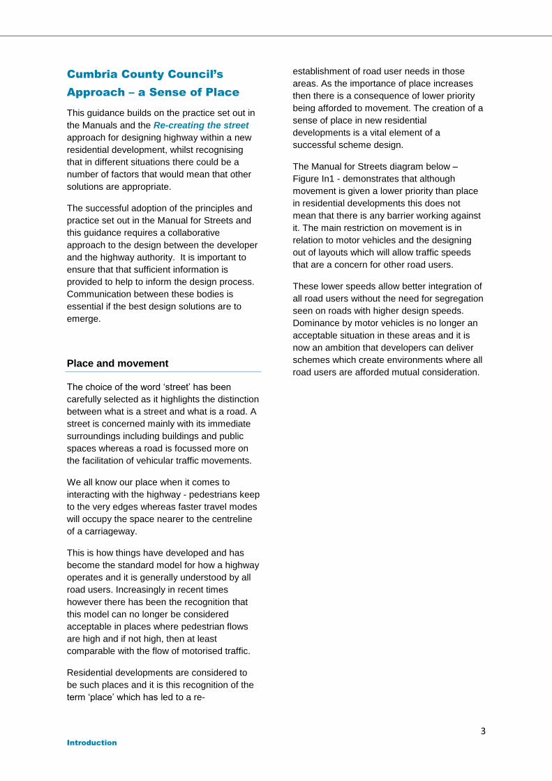
The Manual for Streets diagram below –
Figure In1 - demonstrates that although
movement is given a lower priority than place
in residential developments this does not
mean that there is any barrier working against
it. The main restriction on movement is in
relation to motor vehicles and the designing
out of layouts which will allow traffic speeds
that are a concern for other road users.
These lower speeds allow better integration of
all road users without the need for segregation
seen on roads with higher design speeds.
Dominance by motor vehicles is no longer an
acceptable situation in these areas and it is
now an ambition that developers can deliver
schemes which create environments where all
road users are afforded mutual consideration.
4 Introduction
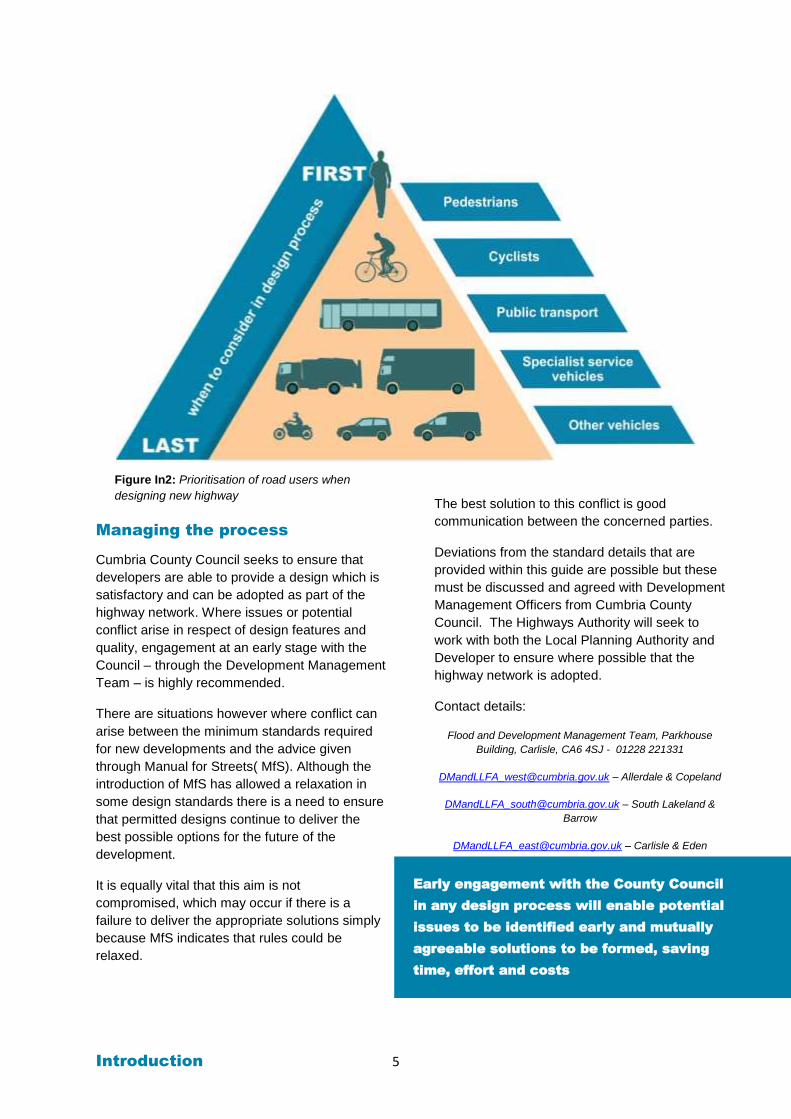
A hierarchy of road users in new residential
developments will generally prioritise those
who are most vulnerable or those seeking
access to public transport above all other
modes of transport. This ‘scale’ of prioritisation
in the design process can be demonstrated in
Figure In2 below.
Permeability and ease of access for
pedestrians is essential to the successful
design of residential developments. The
correct identification of desire lines and
removal of barriers all help to encourage an
environment which is dominated by the non-
motor vehicle road user. Additionally, the
encouragement of walking and cycling is
beneficial to peoples’ health through exercise
and the reduction in pollution associated with
motor vehicles.
Motorways All about moving at high speed, with infrequent delays and low chance of conflict between vehicles.
High streets A destination for many with all types of road user mixing in substantial numbers. Not generally identified as a through route.
Rural lanes Important for allowing people to move between destinations but also have some place status due to the scenery and low traffic levels.
Residential streets Tend to be the end destination or origin of trips for people so traffic is low and slow putting greater emphasis on the place itself.
Figure In1: Movement / Place status matrix
Introduction 5
Figure In2: Prioritisation of road users when
designing new highway
Managing the process
Cumbria County Council seeks to ensure that
developers are able to provide a design which is
satisfactory and can be adopted as part of the
highway network. Where issues or potential
conflict arise in respect of design features and
quality, engagement at an early stage with the
Council – through the Development Management
Team – is highly recommended.
There are situations however where conflict can
arise between the minimum standards required
for new developments and the advice given
through Manual for Streets( MfS). Although the
introduction of MfS has allowed a relaxation in
some design standards there is a need to ensure
that permitted designs continue to deliver the
best possible options for the future of the
development.
It is equally vital that this aim is not
compromised, which may occur if there is a
failure to deliver the appropriate solutions simply
because MfS indicates that rules could be
relaxed.
The best solution to this conflict is good
communication between the concerned parties.
Deviations from the standard details that are
provided within this guide are possible but these
must be discussed and agreed with Development
Management Officers from Cumbria County
Council. The Highways Authority will seek to
work with both the Local Planning Authority and
Developer to ensure where possible that the
highway network is adopted.
Contact details:
Flood and Development Management Team, Parkhouse
Building, Carlisle, CA6 4SJ - 01228 221331
[email protected] – Allerdale & Copeland
[email protected] – South Lakeland &
Barrow
[email protected] – Carlisle & Eden
Early engagement with the County Council
in any design process will enable potential
issues to be identified early and mutually
agreeable solutions to be formed, saving
time, effort and costs
Introduction 6
Provision of Pre-application
Advice
The County Council welcomes and encourages
discussions before a developer submits a
planning application.
These discussions can result in better quality
applications which stand a better chance of a
successful outcome and help speed up the
decision making process after submission. As a
consequence they can help to minimise
subsequent costs and avoid abortive
applications. Consultations should include
discussions on sustainable drainage as a key
requirement on NPPF.
There will be a charge for pre-application
discussions, further information on this can be
found in Appendix 2
Information required
In order to be able to provide useful advice and
guidance, a sufficient level of information needs
to be provided before any pre-application advice
is given.
For Small developments (single dwelling /
householder applications) , the minimum
information required is as follows:-
Site address
Site plans (showing location, boundary,
existing and proposed site layouts including
access arrangements)
Description of proposed development.
Drainage proposals for foul and surface
water.
For Minor ( 5 dwellings or less) or Major or
Strategic proposals in addition to the above, the
scope of information to be provided should be
discussed with the Local Highway Authority but
could include the following information:-
Details of the existing use of the site,
including planning permission history if
applicable.
A Stage 1 Road Safety Audit (including copy
of the brief and designer’s response) for the
proposed site layout and/or access
arrangement together with amended plans.
Relevant data collected to date, such as
traffic counts, accident history, speed
surveys.
Summary of reasons supporting site
access/highway works proposals, including
plan (scale 1:200) with achievable visibility
splays indicated.
Scoping for a Transport Statement /
Assessment or a draft of these documents.
Location plan of key services and facilities
indicating locations of education,
employment, food and non-food retail,
health care and public transport facilities.
Parking Strategy, including provision of
parking for all forms of transport.
Any further information considered critical to
the proposal at pre-application stage.
Flood Risk Assessment/Statement
Drainage Strategy/ Statement & Sketch
layout plan
Details of any existing rights of way which
may need to be stopped/up or diverted.
Appendix 9 provides further guidance on
this matter.
Further detail on standards that the County
Council expect developments to comply with
can be found in Appendix 4.
Where the Highway Authority is invited to attend
a pre-application meeting, all of the relevant
information should be provided 10 working days
prior otherwise the meeting will need to be
rescheduled.
Upon receipt of all necessary information, the
Council will aim to provide a written response
(either by email or letter) within 21 days.
Please Note
The Highway Authority and Lead Local Flood
Authority formal response to any planning
application is made taking account of revisions to
the proposals, any changed circumstances
and/or information. As such, we cannot offer pre-
application advice that can bind the Council but
we will give you the best advice possible based
on the information that you provide. The final
decision on any planning application is taken
Introduction 7
Highway adoption process
With the exception of private shared driveways,
housing estate roads must be designed and
constructed to a standard considered acceptable
for roads likely to be adopted as highways
maintainable at public expense.
A new road can be adopted by Cumbria County
Council into the highway network if;
It serves more than five dwellings; and
It has been constructed to a standard acceptable to the county council highways department; and
It uses a design speed of 20mph as its upper limit; and
It provides sufficient parking places for residents and visitors; and
It serves a highway purpose
Does not lead to potential ransom demands in the future
By encouraging a more innovative approach from
developers to designs, it is conceded that the
adherence to a strict list of design standards is
unlikely to assist in this aim. This creates a
potential weakness in this new approach as if
standards are no longer absolute requirements,
developers may produce designs which are not
considered to be acceptable by the Highway
Authority.
Manual for Streets does suggest a number of
ways in which this weak or ‘grey’ area could be
lessened such as the provision of compelling
evidence by the developer to prove that a design
will satisfy.
Every one of these suggestions will work best if
both the developer and the Highway Authority
are able to communicate early on in the design
process.
Works within existing highway boundary
Developers are reminded that no works can take
place in the existing highway without the
approval of the Highway Authority. Any works
within the highway shall only take place when
appropriate licences have been issued and /or a
Section 278 Agreement has been signed.
Further detail in relation to highway agreements /
obligations can be found in Appendix 8.
Boundaries of adopted highways
Highway boundaries in residential developments
should be clearly indicated physically on the
ground in some manner. The method by which
this is done should not detract from the character
of a street or road.
An adopted highway verge which is adjacent to
private gardens on an open plan estate will
require special attention to ensure that the rights
of the Highway Authority, statutory undertakers
and the public are fully understood by purchasers
of the adjoining property.
Developers should ensure that grassed areas
which are required to form part of the adopted
highway are not conveyed to future purchasers in
advance of a Section 38 road adoption
Agreement being entered into, so that the
Developer has the legal capacity to dedicate all
necessary land as highway.
Purchasers must be made aware that if the
grassed areas/highway verges are conveyed to
them following the entering into of the Section 38
Agreement that they will be required to ensure
that the new owners should be prohibited from
building walls or fences or planting trees or
shrubs on the grassed areas/highway verge so
as to restrict visibility and that the statutory
undertakers may excavate their services at any
time.
The Highway Authority will work with the
Local Planning Authorities to ensure that no
ransom strips are left at the end of turning
heads. Adoption should therefore extend to
the edge of the land ownership/title boundary
and Section 38 Agreement drawings should
clearly reflect this, with suitable dimensions.
Introduction 8
Prior to the entering into of a Section 38
Agreement, an Advance Payment Code Notice
(APC) may be served following the passing of
plans by the relevant Planning Authority. This
Notice requires the payment of a sum to the
Council in satisfaction of the cost of making up
the private street to an adoptable standard before
building works commence. Such a Notice is
generally only discharged, and any payments
made refunded, once the Section 38 Agreement
is entered into or the private street is adopted as
highway maintainable at the public expense.
Please see Appendix 8 for further detaills of the
APC procedure. Geotechnical features shall be
designed and certified in accordance with BS EN
1997-1 Geotechnical Design and the Design
Manual for Roads and Bridges HD 22/08
Managing Geotechnical Risk.
Geotechnical features to which these procedures
apply includes earthworks, strengthened
earthworks and earth retaining structures
supporting the highway or otherwise near it,
whether or not they are to be adopted as publicly
maintainable. HD 22/08 defines the features
more fully and describes the technical
requirements, standards and formal certification
procedures that should be met.
Further details can be found in Appendix 5 in
relation to commuted sums.
Health and safety (Construction Design
and Management Regulations)
No highway adoption shall be made without a
suitable Health and Safety file being submitted
which shall include all record drawings of roads,
drainage and street lighting.
Road safety audit
The following extracts are taken from Cumbria
County Council’s policy on road safety audits and
demonstrate their direct relation to new
developments and changes to the existing
highway.
The road safety audit process is used to identify
any issues with a new highway design or change
to existing highway that could pose a risk to a
road user. Road safety audits are carried out
independent of any persons involved in the
design. The aim is to provide a fresh and
uninfluenced opinion on a scheme. Upon
identifying any issues, a report is prepared which
makes recommendations intended to mitigate
against them. These recommendations could
suggest the removal of certain elements from the
design or possibly a replacement design feature
that would better guarantee road safety.
Road safety audits are a requirement of both the
Section 38 and 278 agreements as they are
essential components of the highway adoption
process.
Everyone must play their part in ensuring safe
environments are being developed and while the
audit report must be done in isolation by the audit
team, group discussions with road safety experts
are encouraged
A Stage 1 Road Safety Audit together with the
brief and copies of the information provided
should be submitted as part of the planning
application for the development. This helps to
avoid significant issues arising at later stages
once planning consent has been granted and
also provides evidence with regards the safety of
the design in order to satisfy both Highways and
Planning Authorities.
A Developer may request Cumbria County
Council to undertake a road safety audit on their
behalf or they may appoint an external party for
the purpose. There is a cost associated with
either option to cover the vetting process.
‘All schemes, regardless of cost, that have a
significant impact on road users or make
significant changes to the highway geometry,
traffic flow, lighting, signalling, signage,
landscaping or carriageway markings will be
subject to a full Road Safety Audit’.
‘All new road schemes and highway
improvements which have a more minor impact
on road users will be subject at a minimum to a
safety check in the form of a brief Road Safety
Advice Note.’
Introduction 9
Consideration of risk
Developers may be aware from the outset of a
scheme of potential risks in their design which
would be picked up by a road safety audit. If
these risks have been considered fully and if the
likelihood and resultant severity of any incident is
determined to be low then the design could
remain as planned without the need to make
changes.
The Chartered Institution of Highways and
Transportation (CIHT) made provision for
introducing likelihood of collisions and resulting
severity of those collisions in their paper Highway
Risk & Liability Claims, A Practical Guide to Appendix
C (UK Roads Board, 2005). Currently, Cumbria
County Council require this risk assessment be
used for any issue raised through a road safety
audit report in conservation areas and town
centres within the County.
It is therefore necessary that all applications
requiring works within the highway to be
accompanied by a stage 1/2 safety audit, to
ensure that all safety aspects of the works are
identified and remediated.
Adoption and use of open spaces
The Highway Authority will adopt grassed
areas/verges as publicly maintainable only where
there are adjacent Local Distributor Roads and
on lower category roads only where required for
highway visibility, vehicle overhang, statutory
services or to enable future highway
improvements.
Such maintenance will exclude trees, shrubs and
ground cover planting, none of which will
be accepted within the highway unless the
developer has made secure arrangements for
their future maintenance. This will normally occur
through a financial contribution though a Section
106 agreement.
In respect of other open space within housing
sites, developers will need to ensure that secure
arrangements are made for future maintenance
and these arrangements should be made explicit
at the planning application stage. This may
appropriately be undertaken by individual
residents if the space is to be allocated to
individual ownerships during the sale of property.
In other instances, the developers will
themselves need to make arrangements for the
ongoing maintenance which will need to be
recognised in a legal agreement. As above,
these spaces should clearly be defined in a
Section 106 agreement.
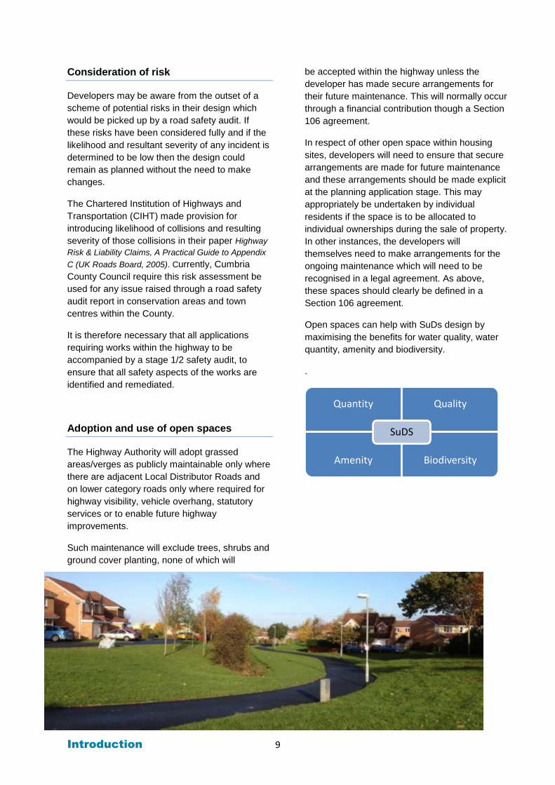
Open spaces can help with SuDs design by
maximising the benefits for water quality, water
quantity, amenity and biodiversity.
.
Quantity Quality
Amenity Biodiversity
SuDS
Part 1 10
Part 1 New Residential Development
Chapters
A. Road hierarchy
B. Visibility
C. Carriageway widths
D. Junctions and radii
E. Turning areas
F. Speed management
G. Gradients
H. Vertical clearance
I. Signs and markings
J. Parking
K. Utility services
L. Lighting
M. Landscaping
N. Sustainable Drainage Systems
Part 1 Chapter A: Road hierarchy 11
Chapter A. Road
hierarchy
This guide provides recommendations as to
the most suitable geometry and best practice
advice to use in designing new sections of
adoptable highway. Amongst the most
problematic issues when it comes to applying
MfS is that the advice can be found to be too
flexible. The risk associated with this flexibility
is that designs could be produced which fail to
perform well once constructed leading to the
introduction of remedial works that can ruin an
area’s character. Minimum standards for
certain elements within a development are
therefore necessary to ensure that new
additions to the highway network are
acceptable for adoption.
It is for this reason, that a general description
of the road types expected to form or connect
to residential developments has been included
here along with some baseline standards
expected to apply to each type. Developers
are reminded that early consultation between
themselves and the Highway Authority will
allow for early decisions to be made on any
departures from these recommendations.
There is no reason why any particular issue
cannot be discussed and negotiated if
compelling evidence can be provided for
departing from the recommendations given
here.
The classification and treatment of a road
appropriate to its function is essential in
maintaining a reasonable balance between the
safe and efficient accommodation of all road
users without causing unnecessary delay or
unreasonable hardship on any one particular
group.
In general, it should be the case that any new
road which has a principle purpose of serving
residential properties will be suited to traffic
types and flows appropriate to that purpose.
By designing to this function, as opposed to a
demand, the concept of ‘place’ can play a
significant role in the creation and sustaining of
an area’s character, community and other
facets which have a value and benefit to
quality of living.
Residential developments, with their emphasis
on people, means that the roads which serve
them will be expected to have low traffic flows
and low numbers of heavy vehicles using
them.
Permeability
The ability of people to move through a
development and to connect efficiently with the
existing road network is vital and should be a
primary consideration in new layout designs.
This desire for permeability is one that is
shared by all road users, from those on foot to
those operating private motor vehicles.
Generally it will be the case that the larger a
development is then the greater the need will
be for multiple connections with the network.
The purpose behind this is to minimise any
disruption to a majority, if not all residents if
sections of road are subjected to a closure or
blockage of some kind. In addition to this a
permeable layout allows for a diversity of
movement options which helps to create
dynamic streetscapes, rather than a car a
dominated layout.
Severance of routes should be guarded
against through the provision of appropriate
alternatives. Designs must also anticipate any
misuse of this new network by non-residents
simply who seek to use the road as a short-
cut. This should be discouraged through the
selection of alignments and features which will
manage traffic speeds.
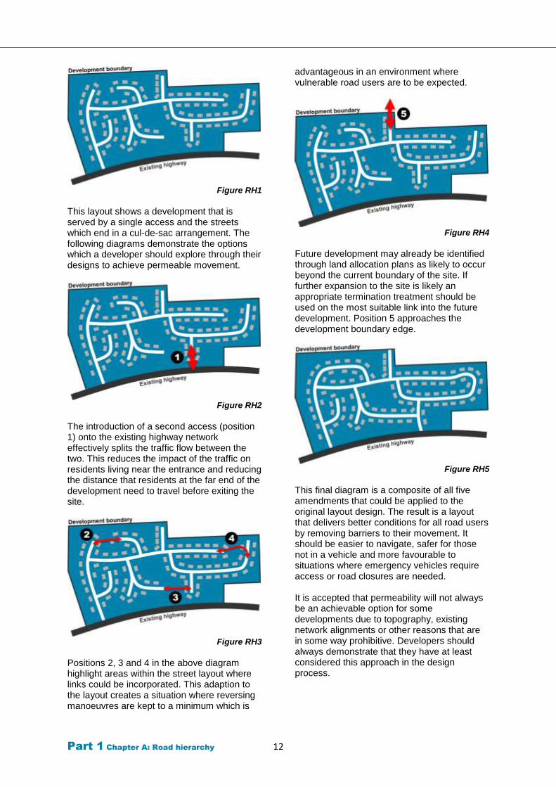
Figures RH1 to RH5 collectively draw a
comparison between a non-permeable
development and one that has been designed
with permeability in mind.
Part 1 Chapter A: Road hierarchy 12
Figure RH1
This layout shows a development that is served by a single access and the streets which end in a cul-de-sac arrangement. The following diagrams demonstrate the options which a developer should explore through their designs to achieve permeable movement.
Figure RH2
The introduction of a second access (position 1) onto the existing highway network effectively splits the traffic flow between the two. This reduces the impact of the traffic on residents living near the entrance and reducing the distance that residents at the far end of the development need to travel before exiting the site.
Figure RH3
Positions 2, 3 and 4 in the above diagram highlight areas within the street layout where links could be incorporated. This adaption to the layout creates a situation where reversing manoeuvres are kept to a minimum which is
advantageous in an environment where vulnerable road users are to be expected.
Figure RH4
Future development may already be identified through land allocation plans as likely to occur beyond the current boundary of the site. If further expansion to the site is likely an appropriate termination treatment should be used on the most suitable link into the future development. Position 5 approaches the development boundary edge.
Figure RH5
This final diagram is a composite of all five amendments that could be applied to the original layout design. The result is a layout that delivers better conditions for all road users by removing barriers to their movement. It should be easier to navigate, safer for those not in a vehicle and more favourable to situations where emergency vehicles require access or road closures are needed. It is accepted that permeability will not always be an achievable option for some developments due to topography, existing network alignments or other reasons that are in some way prohibitive. Developers should always demonstrate that they have at least considered this approach in the design process.
Part 1 Chapter A: Road hierarchy 13
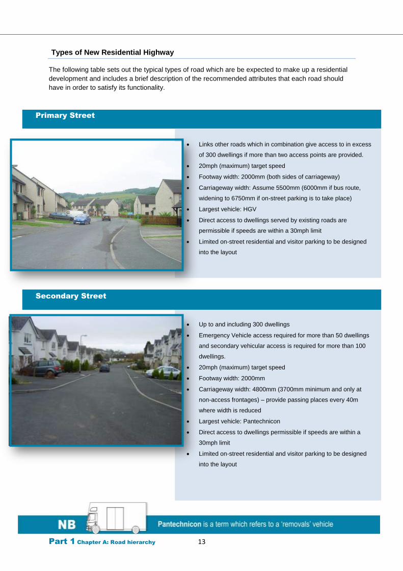
Types of New Residential Highway
The following table sets out the typical types of road which are be expected to make up a residential
development and includes a brief description of the recommended attributes that each road should
have in order to satisfy its functionality.
Primary Street
Links other roads which in combination give access to in excess
of 300 dwellings if more than two access points are provided.
20mph (maximum) target speed
Footway width: 2000mm (both sides of carriageway)
Carriageway width: Assume 5500mm (6000mm if bus route,
widening to 6750mm if on-street parking is to take place)
Largest vehicle: HGV
Direct access to dwellings served by existing roads are
permissible if speeds are within a 30mph limit
Limited on-street residential and visitor parking to be designed
into the layout
Secondary Street
Up to and including 300 dwellings
Emergency Vehicle access required for more than 50 dwellings
and secondary vehicular access is required for more than 100
dwellings.
20mph (maximum) target speed
Footway width: 2000mm
Carriageway width: 4800mm (3700mm minimum and only at
non-access frontages) – provide passing places every 40m
where width is reduced
Largest vehicle: Pantechnicon
Direct access to dwellings permissible if speeds are within a
30mph limit
Limited on-street residential and visitor parking to be designed
into the layout
Part 1 Chapter A: Road hierarchy 14
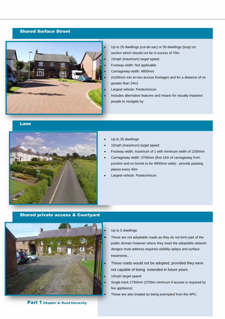
Shared Surface Street
Up to 25 dwellings (cul-de-sac) or 50 dwellings (loop) on
section which should not be in excess of 70m
15mph (maximum) target speed
Footway width: Not applicable
Carriageway width: 4800mm
(4100mm min at non-access frontages and for a distance of no
greater than 24m)
Largest vehicle: Pantechnicon
Includes alternative features and means for visually impaired
people to navigate by
Lane
Up to 25 dwellings
10mph (maximum) target speed
Footway width: maximum of 1 with minimum width of 1200mm
Carriageway width: 3700mm (first 15m of carriageway from
junction and on bends to be 4800mm wide) - provide passing
places every 40m
Largest vehicle: Pantechnicon
Shared private access & Courtyard
Up to 5 dwellings
These are not adoptable roads as they do not form part of the
public domain however where they meet the adoptable network
designs must address required visibility splays and surface
treatments..
These roads would not be adopted, provided they were
not capable of being extended in future years
10mph target speed
Single track 2750mm (3700m minimum if access is required by
fire appliance)
These are also treated as being exempted from the APC.
Part 1 Chapter A: Road hierarchy 15
Care must be taken where site outlines
contain or border Public Rights of Way,
please contact our Countryside Access
team.
Footpaths & Cycle Tracks
Other types of highway which may be
adoptable by the Highway Authority include
footpaths and cycle tracks that do not follow
the route of the main carriageway.
Footpaths
Footpaths are fully adoptable as highways just
as long as they form some useful part of the
network. They must be provided where shared
surface solutions are not possible or are
determined not to be appropriate. 2m is
usually sufficient width to accommodate foot
traffic as ample space is available for
pushchairs, wheelchairs and mobility scooters.
Routes which include steps will not be
considered for adoption.
Cycle Tracks
It is an important requirement that any new
highway should be able to incorporate cycles
and permit them to travel with low risk. This is
to be achieved through the application of low
design speeds and a conscientious design
layout. There are instances however when
cyclists should be allowed, even encouraged
to leave the confines of the carriageway and
take advantage of the flexibility which cycling
promotes.
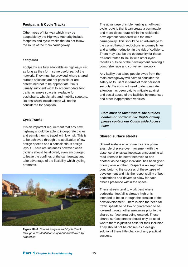
Figure RH6: Shared footpath and Cycle Track
through a residential development overlooked by
properties
The advantage of implementing an off-road
cycle route is that it can create a permeable
and more direct route within the residential
development compared with the main
carriageway. This should be an advantage to
the cyclist through reductions in journey times
and a further reduction in the risk of collisions.
There may also be the opportunity for these
off-road routes to link in with other cycle
facilities outside of the development creating a
comprehensive and convenient network.
Any facility that takes people away from the
main carriageway will have to consider the
safety of its users in terms of their personal
security. Designs will need to demonstrate
attention has been paid to mitigate against
anti-social abuse of the facilities by motorised
and other inappropriate vehicles.
Shared surface streets
Shared surface environments are a prime
example of place over movement with the
absence of physical footways encouraging all
road users to be better behaved to one
another as no single individual has been given
priority over another. Respect is an important
contributor to the success of these types of
development and it is the responsibility of both
pedestrians and drivers to allow for each
other’s presence within the space.
These streets tend to work best where
pedestrian footfall is already high or is
intended to be so through the creation of the
new development. There is also the need for
traffic speeds to be low or guaranteed to be
lowered through other measures prior to the
shared surface area being entered. These
shared surface streets should only be used
where there is justified case for their inclusion.
They should not be chosen as a design
solution if there little chance of any practical
success.
Part 1 Chapter A: Road hierarchy 16
Where multiple desire lines (the most direct
and desirable routes) are present for
pedestrians, the shared surface can offer a
good alternative option to the traditional formal
application of straight footways with crossings.
Such formality can create frustration for
pedestrians who will often choose their own
routes rendering the design inefficient.
The choice of surfacing material to apply to the
shared surface will determine how well it is
understood by road users. Visual clues should
be included in the design that will create safe
areas for pedestrians. These areas should act
as portions of the highway where vehicles are
less likely to enter even on a shared surface
and could be created through a visual
segregation line created in the surface through
some appropriate method.
The use of shared surface areas will only ever
be acceptable if the concerns of impaired
users are addressed. Developments should
also strive to be “Dementia Friendly”. The
common problem that shared spaces can
present for visual impairment includes
confusion due to the blank canvas of highway
without easily identifiable infrastructure to
follow. Appropriate mitigation measures must
be built into the design to allow access for all.
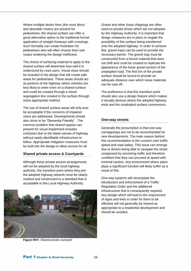
Shared private access & Courtyards
Although these private access arrangements
will not be adopted by the local highway
authority, the transition point where they join
the adopted highway network must be clearly
marked and constructed to a standard that is
acceptable to the Local Highway Authority.
Figure RH7: Shared private courtyard
Gravel and other loose chippings are often
used on private drives which are not adopted
by the Highway Authority. It is important that
design measures are in place to negate the
possibility of this surface being transferred
onto the adopted highway. In order to achieve
this, gravel traps can be used to provide the
necessary barrier. The gravel trap must be
constructed from a bound material that does
not shift and could be created to replicate the
appearance of the loose gravel section of the
unadopted road. The first 5m of the private
surface should be bound to provide an
adequate distance over which loose materials
can be cast off.
The preference is that this transition point
should also use a design feature which makes
it visually obvious where the adopted highway
ends and the unadopted surface commences.
One-way streets
Generally the presumption is that one-way
carriageways are not to be recommended for
new developments. The main reason behind
this recommendation is the concern over traffic
speed and road safety. This issue can emerge
due to drivers being able to navigate the street
unopposed by oncoming traffic and therefore
confident that they can proceed at speed with
minimal caution. Any environment where place
plays a significant function will likely suffer as a
result of this.
One-way systems will necessitate the
introduction and enforcement of a Traffic
Regulation Order and the additional
infrastructure that is consequently required.
Any design which will lead to the requirement
of signs and lines in order for them to be
effective will not generally be viewed as
appropriate to a residential development and
should be avoided.
Part 1 Chapter B: Visibility 17
Chapter B. Visibility
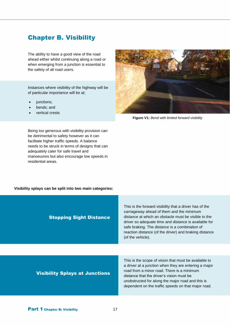
The ability to have a good view of the road
ahead either whilst continuing along a road or
when emerging from a junction is essential to
the safety of all road users.
Instances where visibility of the highway will be
of particular importance will be at;
junctions;
bends; and
vertical crests
Being too generous with visibility provision can
be detrimental to safety however as it can
facilitate higher traffic speeds. A balance
needs to be struck in terms of designs that can
adequately cater for safe travel and
manoeuvres but also encourage low speeds in
residential areas.
Figure V1: Bend with limited forward visibility
Visibility splays can be split into two main categories:
Stopping Sight Distance
This is the forward visibility that a driver has of the
carriageway ahead of them and the minimum
distance at which an obstacle must be visible to the
driver so adequate time and distance is available for
safe braking. The distance is a combination of
reaction distance (of the driver) and braking distance
(of the vehicle).
Visibility Splays at Junctions
This is the scope of vision that must be available to
a driver at a junction when they are entering a major
road from a minor road. There is a minimum
distance that the driver’s vision must be
unobstructed for along the major road and this is
dependent on the traffic speeds on that major road.
Part 1 Chapter B: Visibility 18
Important factors affecting visibility
Visibility should be checked at junctions and
along the street.
Visibility is measured both horizontally and
vertically.
Using plan views of proposed layouts,
checks for visibility in the horizontal plane
ensure that views are not obscured by
vertical obstructions.
Checking visibility in the vertical plane is
then carried out to ensure that views in the
horizontal plane are not compromised by
obstructions such as the crest of a hill, or a
bridge at a dip in the road ahead.
It also takes into account the variation in
driver eye height and the height range of
obstructions. Eye height is assumed to
range from 1.05m (for car drivers) to 2m (for
lorry drivers).
Drivers need to be able to see obstructions
2m high down to a point 600mm above the
carriageway. The latter dimension is used to
ensure small children can be seen.
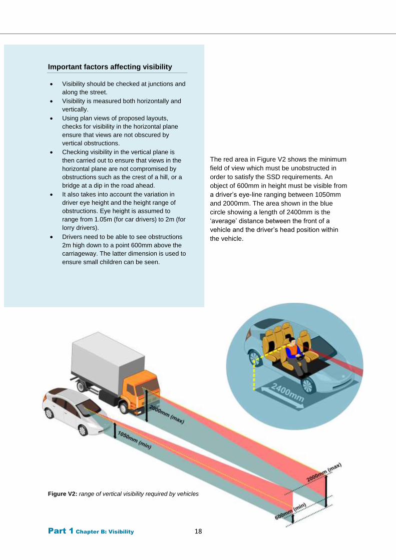
The red area in Figure V2 shows the minimum
field of view which must be unobstructed in
order to satisfy the SSD requirements. An
object of 600mm in height must be visible from
a driver’s eye-line ranging between 1050mm
and 2000mm. The area shown in the blue
circle showing a length of 2400mm is the
‘average’ distance between the front of a
vehicle and the driver’s head position within
the vehicle.
Figure V2: range of vertical visibility required by vehicles
Part 1 Chapter B: Visibility 19
The calculation above, used to derive
the Stopping Sight Distance (SSD) is
comprised of two component
calculations, one for each type of
distance being measured. The first
part of the calculation finds the
‘reaction distance’ whilst the remaining
part which is then added finds the
‘braking distance’.
MfS uses an indicative ceiling of 37mph, below
which its principles and guidance can be used
with confidence. Above this threshold figure of
37mph it is therefore considered more
appropriate to switch back to the DMRB
figures which were used previously in all
situations. It is important to appreciate when
using the data from DMRB, that it was created
by the Highways Agency, specifically to design
for trunk roads and it is therefore not suitable
for applying to residential streets without any
critical analysis being done.
An SSD uses a wet surface as the basis for
determining the total distance required and is
done so to ensure that a worst case scenario
has been considered.
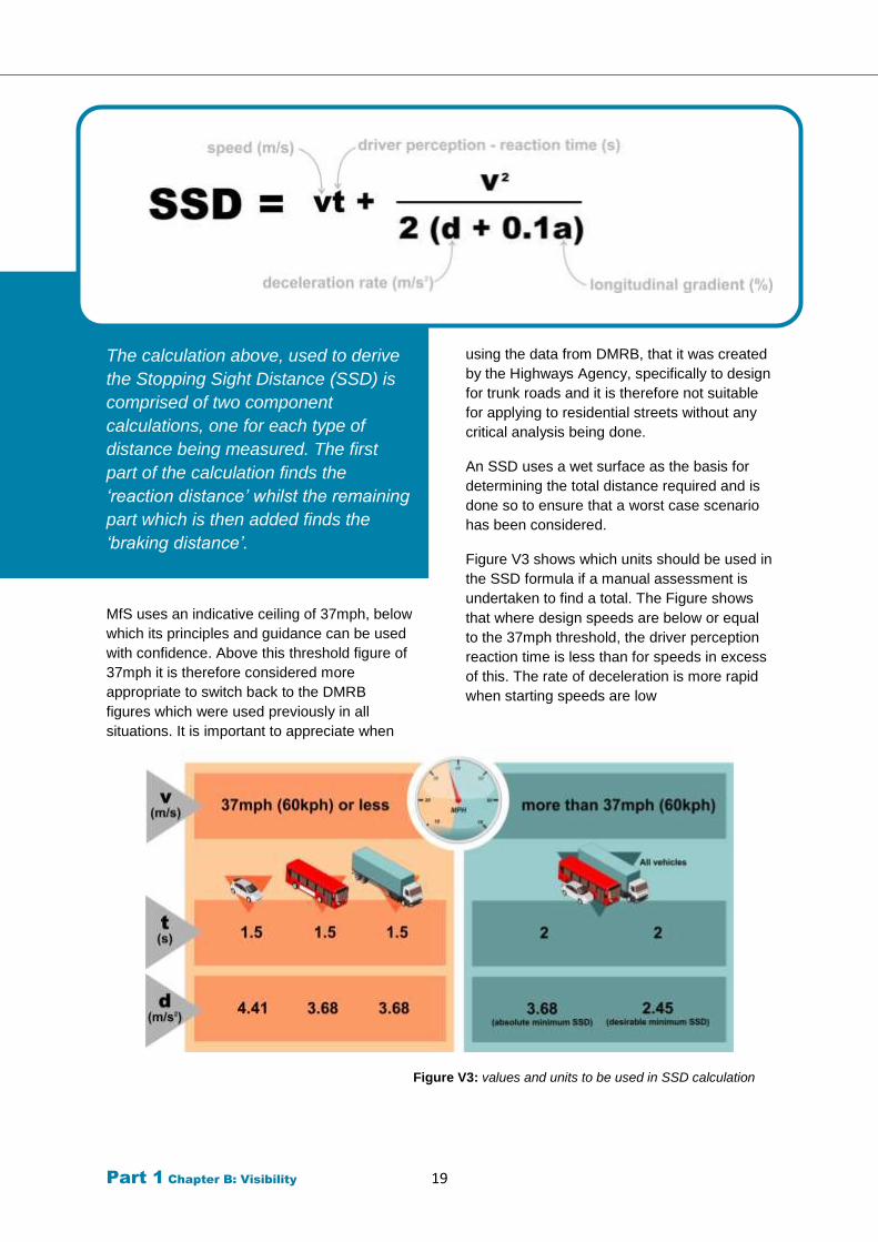
Figure V3 shows which units should be used in
the SSD formula if a manual assessment is
undertaken to find a total. The Figure shows
that where design speeds are below or equal
to the 37mph threshold, the driver perception
reaction time is less than for speeds in excess
of this. The rate of deceleration is more rapid
when starting speeds are low
Figure V3: values and units to be used in SSD calculation
Part 1 Chapter B: Visibility 20
Existing roads with actual 85th
percentile recorded speed data
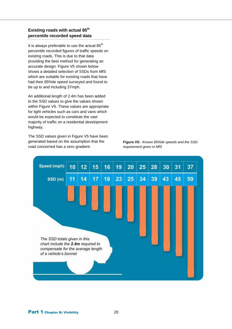
It is always preferable to use the actual 85th
percentile recorded figures of traffic speeds on
existing roads. This is due to that data
providing the best method for generating an
accurate design. Figure V5 shown below
shows a detailed selection of SSDs from MfS
which are suitable for existing roads that have
had their 85%ile speed surveyed and found to
be up to and including 37mph.
An additional length of 2.4m has been added
to the SSD values to give the values shown
within Figure V5. These values are appropriate
for light vehicles such as cars and vans which
would be expected to constitute the vast
majority of traffic on a residential development
highway.
The SSD values given in Figure V5 have been
generated based on the assumption that the
road concerned has a zero gradient.
Figure V5: Known 85%ile speeds and the SSD
requirement given in MfS
Part 1 Chapter B: Visibility 21
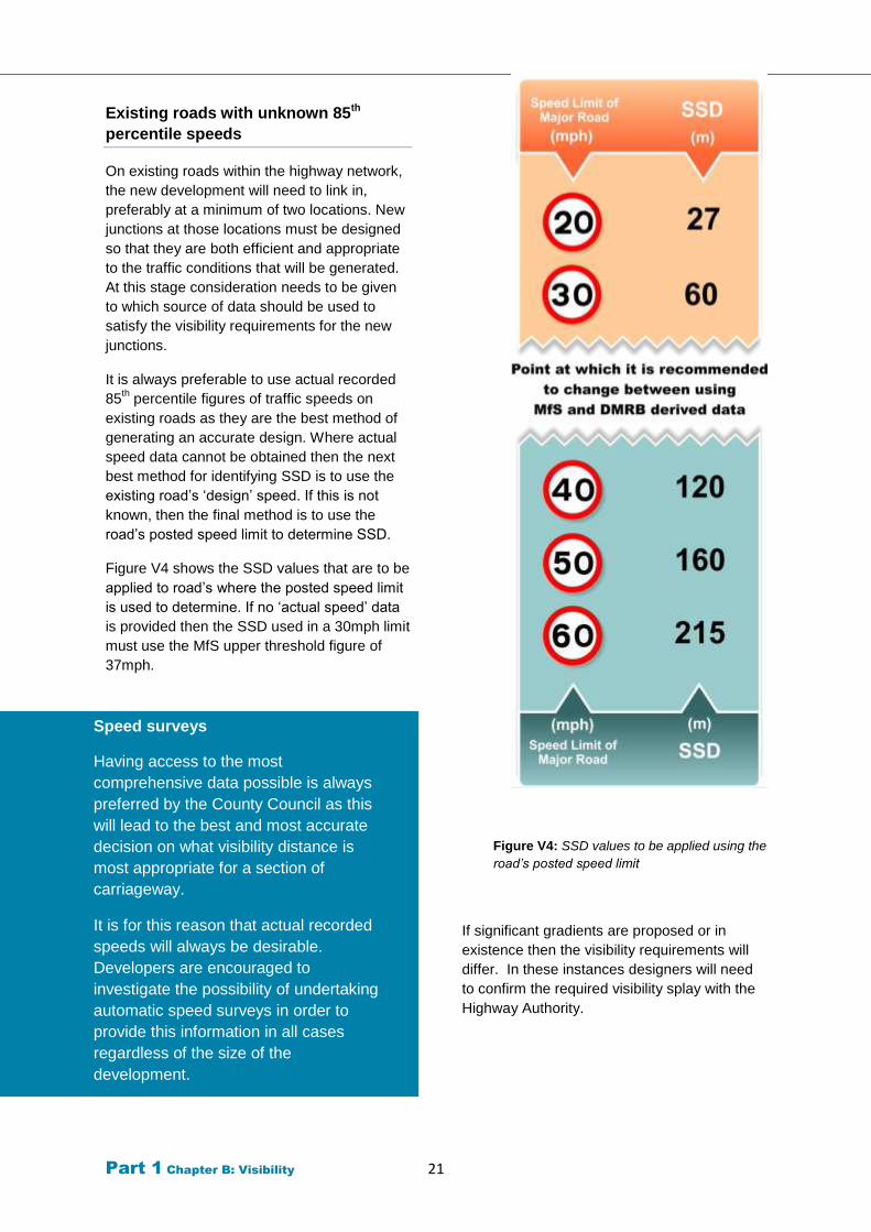
Existing roads with unknown 85th
percentile speeds
On existing roads within the highway network,
the new development will need to link in,
preferably at a minimum of two locations. New
junctions at those locations must be designed
so that they are both efficient and appropriate
to the traffic conditions that will be generated.
At this stage consideration needs to be given
to which source of data should be used to
satisfy the visibility requirements for the new
junctions.
It is always preferable to use actual recorded
85th percentile figures of traffic speeds on
existing roads as they are the best method of
generating an accurate design. Where actual
speed data cannot be obtained then the next
best method for identifying SSD is to use the
existing road’s ‘design’ speed. If this is not
known, then the final method is to use the
road’s posted speed limit to determine SSD.
Figure V4 shows the SSD values that are to be
applied to road’s where the posted speed limit
is used to determine. If no ‘actual speed’ data
is provided then the SSD used in a 30mph limit
must use the MfS upper threshold figure of
37mph.
Figure V4: SSD values to be applied using the
road’s posted speed limit
If significant gradients are proposed or in
existence then the visibility requirements will
differ. In these instances designers will need
to confirm the required visibility splay with the
Highway Authority.
Speed surveys
Having access to the most
comprehensive data possible is always
preferred by the County Council as this
will lead to the best and most accurate
decision on what visibility distance is
most appropriate for a section of
carriageway.
It is for this reason that actual recorded
speeds will always be desirable.
Developers are encouraged to
investigate the possibility of undertaking
automatic speed surveys in order to
provide this information in all cases
regardless of the size of the
development.
Part 1 Chapter B: Visibility 22
Applying gradients
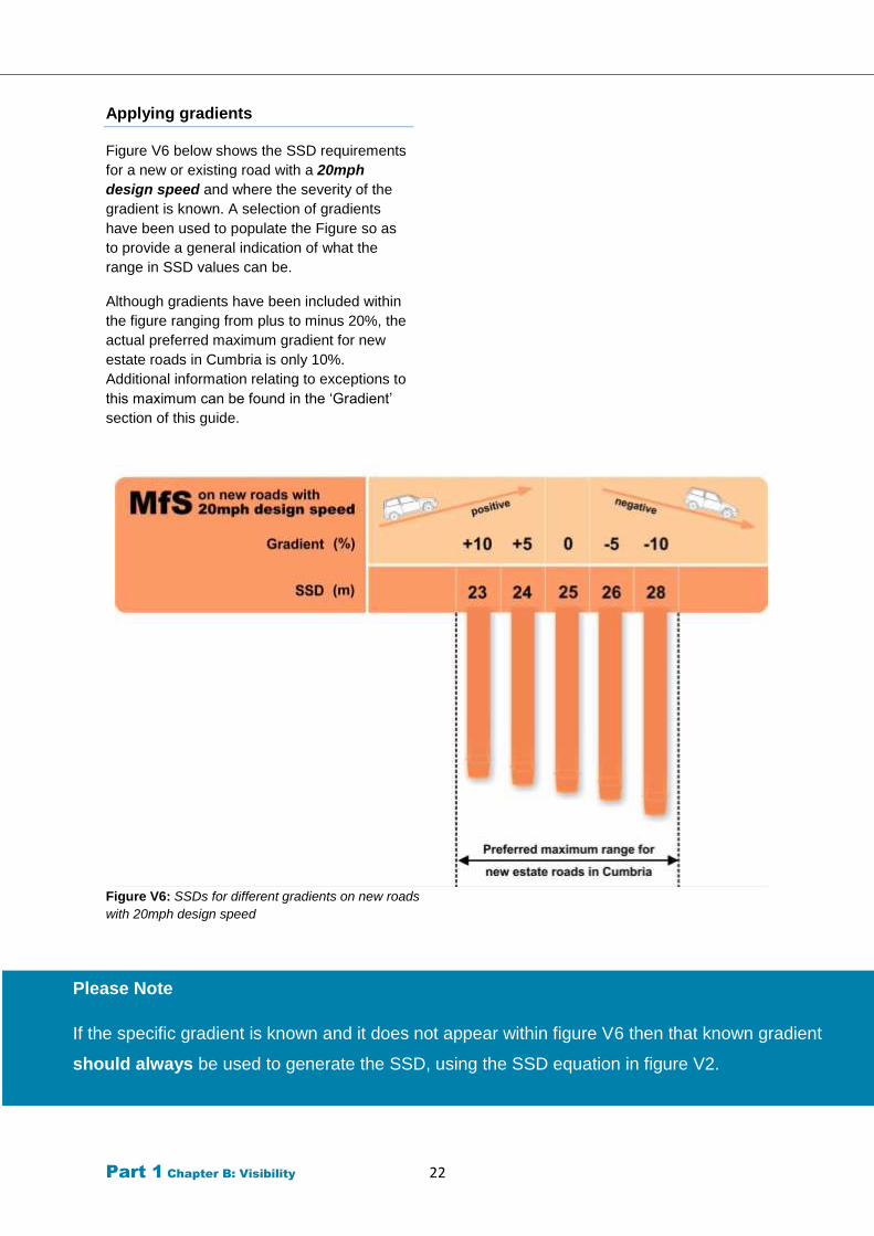
Figure V6 below shows the SSD requirements
for a new or existing road with a 20mph
design speed and where the severity of the
gradient is known. A selection of gradients
have been used to populate the Figure so as
to provide a general indication of what the
range in SSD values can be.
Although gradients have been included within
the figure ranging from plus to minus 20%, the
actual preferred maximum gradient for new
estate roads in Cumbria is only 10%.
Additional information relating to exceptions to
this maximum can be found in the ‘Gradient’
section of this guide.
Figure V6: SSDs for different gradients on new roads
with 20mph design speed
Please Note
If the specific gradient is known and it does not appear within figure V6 then that known gradient
should always be used to generate the SSD, using the SSD equation in figure V2.
Part 1 Chapter B: Visibility 23
Cycleways & shared use facilities
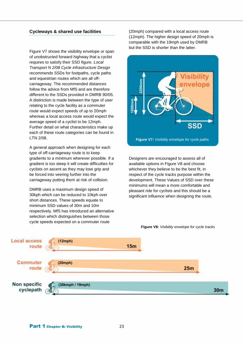
Figure V7 shows the visibility envelope or span
of unobstructed forward highway that a cyclist
requires to satisfy their SSD figure. Local
Transport N 2/08 Cycle infrastructure Design
recommends SSDs for footpaths, cycle paths
and equestrian routes which are all off-
carriageway. The recommended distances
follow the advice from MfS and are therefore
different to the SSDs provided in DMRB 90/05.
A distinction is made between the type of user
relating to the cycle facility as a commuter
route would expect speeds of up to 20mph
whereas a local access route would expect the
average speed of a cyclist to be 12mph.
Further detail on what characteristics make up
each of these route categories can be found in
LTN 2/08.
A general approach when designing for each
type of off-carriageway route is to keep
gradients to a minimum wherever possible. If a
gradient is too steep it will create difficulties for
cyclists on ascent as they may lose grip and
be forced into veering further into the
carriageway putting them at risk of collision.
DMRB uses a maximum design speed of
30kph which can be reduced to 10kph over
short distances. These speeds equate to
minimum SSD values of 30m and 10m
respectively. MfS has introduced an alternative
selection which distinguishes between those
cycle speeds expected on a commuter route
(20mph) compared with a local access route
(12mph). The higher design speed of 20mph is
comparable with the 19mph used by DMRB
but the SSD is shorter than the latter.
Figure V7: Visibility envelope for cycle paths
Designers are encouraged to assess all of
available options in Figure V8 and choose
whichever they believe to be the best fit, in
respect of the cycle tracks purpose within the
development. These Values of SSD over these
minimums will mean a more comfortable and
pleasant ride for cyclists and this should be a
significant influence when designing the route.
Figure V8: Visibility envelope for cycle tracks
Part 1 Chapter B: Visibility 24
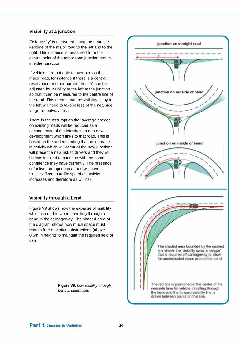
Visibility at a junction
Distance “y” is measured along the nearside
kerbline of the major road to the left and to the
right. This distance is measured from the
central point of the minor road junction mouth
in either direction.
If vehicles are not able to overtake on the
major road, for instance if there is a central
reservation or other barrier, then “y” can be
adjusted for visibility to the left at the junction
so that it can be measured to the centre line of
the road. This means that the visibility splay to
the left will need to take in less of the nearside
verge or footway area.
There is the assumption that average speeds
on existing roads will be reduced as a
consequence of the introduction of a new
development which links to that road. This is
based on the understanding that an increase
in activity which will occur at the new junctions
will present a new risk to drivers and they will
be less inclined to continue with the same
confidence they have currently. The presence
of ‘active frontages’ on a road will have a
similar affect on traffic speed as activity
increases and therefore as will risk.
Visibility through a bend
Figure V9 shows how the expanse of visibility
which is needed when travelling through a
bend in the carriageway. The shaded area of
the diagram shows how much space must
remain free of vertical obstructions (above
0.6m in height) to maintain the required field of
vision.
Figure V9: how visibility through
bend is determined
Part 1 Chapter B: Visibility 25
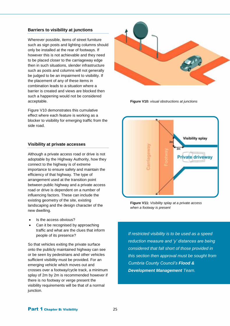
Barriers to visibility at junctions
Wherever possible, items of street furniture
such as sign posts and lighting columns should
only be installed at the rear of footways. If
however this is not achievable and they need
to be placed closer to the carriageway edge
then in such situations, slender infrastructure
such as posts and columns will not generally
be judged to be an impairment to visibility. If
the placement of any of these items in
combination leads to a situation where a
barrier is created and views are blocked then
such a happening would not be considered
acceptable.
Figure V10 demonstrates this cumulative
effect where each feature is working as a
blocker to visibility for emerging traffic from the
side road.
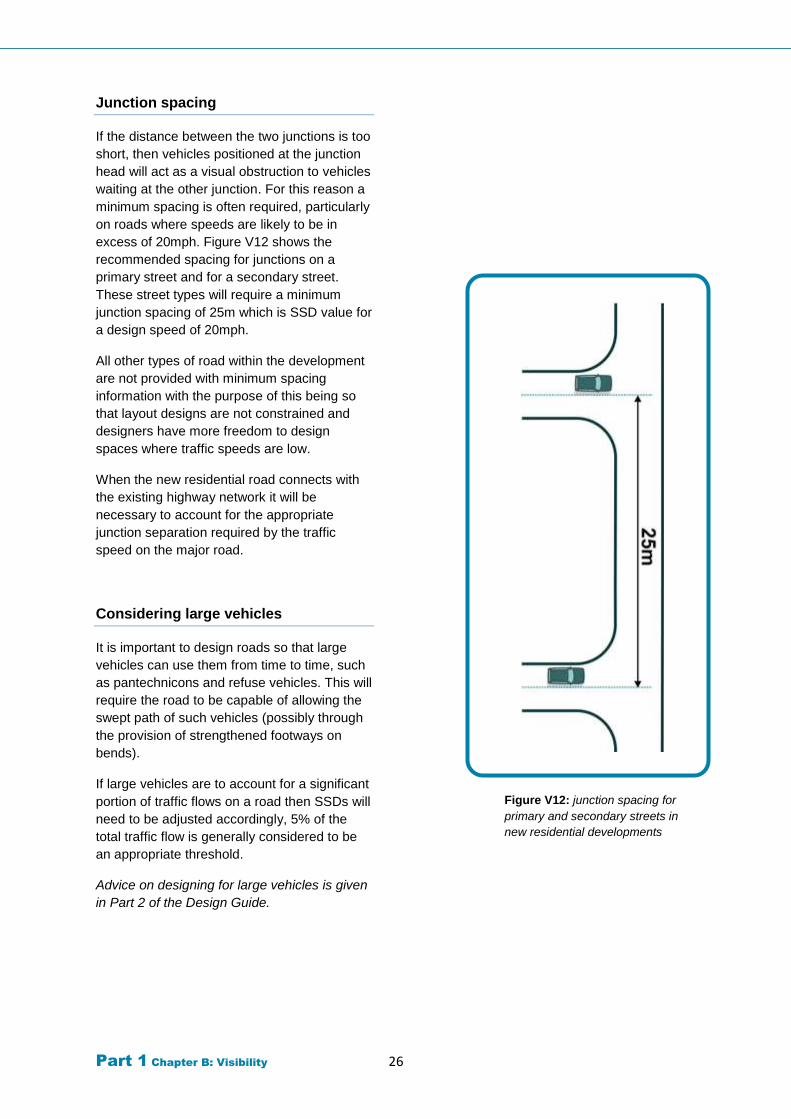
Visibility at private accesses
Although a private access road or drive is not
adoptable by the Highway Authority, how they
connect to the highway is of extreme
importance to ensure safety and maintain the
efficiency of that highway. The type of
arrangement used at the transition point
between public highway and a private access
road or drive is dependent on a number of
influencing factors. These can include the
existing geometry of the site, existing
landscaping and the design character of the
new dwelling.
Is the access obvious?
Can it be recognised by approaching
traffic and what are the clues that inform
people of its presence?
So that vehicles exiting the private surface
onto the publicly maintained highway can see
or be seen by pedestrians and other vehicles
sufficient visibility must be provided. For an
emerging vehicle which moves out and
crosses over a footway/cycle track, a minimum
splay of 2m by 2m is recommended however if
there is no footway or verge present the
visibility requirements will be that of a normal
junction.
Figure V10: visual obstructions at junctions
Figure V11: Visibility splay at a private access
when a footway is present
If restricted visibility is to be used as a speed
reduction measure and ‘y’ distances are being
considered that fall short of those provided in
this section then approval must be sought from
Cumbria County Council’s Flood &
Development Management Team.
Part 1 Chapter B: Visibility 26
Junction spacing
If the distance between the two junctions is too
short, then vehicles positioned at the junction
head will act as a visual obstruction to vehicles
waiting at the other junction. For this reason a
minimum spacing is often required, particularly
on roads where speeds are likely to be in
excess of 20mph. Figure V12 shows the
recommended spacing for junctions on a
primary street and for a secondary street.
These street types will require a minimum
junction spacing of 25m which is SSD value for
a design speed of 20mph.
All other types of road within the development
are not provided with minimum spacing
information with the purpose of this being so
that layout designs are not constrained and
designers have more freedom to design
spaces where traffic speeds are low.
When the new residential road connects with
the existing highway network it will be
necessary to account for the appropriate
junction separation required by the traffic
speed on the major road.
Considering large vehicles
It is important to design roads so that large
vehicles can use them from time to time, such
as pantechnicons and refuse vehicles. This will
require the road to be capable of allowing the
swept path of such vehicles (possibly through
the provision of strengthened footways on
bends).
If large vehicles are to account for a significant
portion of traffic flows on a road then SSDs will
need to be adjusted accordingly, 5% of the
total traffic flow is generally considered to be
an appropriate threshold.
Advice on designing for large vehicles is given
in Part 2 of the Design Guide.
Figure V12: junction spacing for
primary and secondary streets in
new residential developments
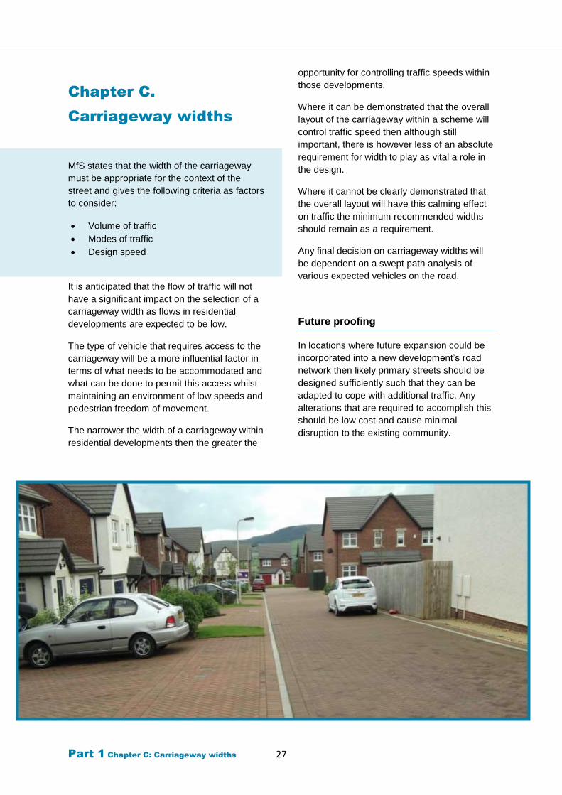
Part 1 Chapter C: Carriageway widths 27
Chapter C.
Carriageway widths
MfS states that the width of the carriageway
must be appropriate for the context of the
street and gives the following criteria as factors
to consider:
Volume of traffic
Modes of traffic
Design speed
It is anticipated that the flow of traffic will not
have a significant impact on the selection of a
carriageway width as flows in residential
developments are expected to be low.
The type of vehicle that requires access to the
carriageway will be a more influential factor in
terms of what needs to be accommodated and
what can be done to permit this access whilst
maintaining an environment of low speeds and
pedestrian freedom of movement.
The narrower the width of a carriageway within
residential developments then the greater the
opportunity for controlling traffic speeds within
those developments.
Where it can be demonstrated that the overall
layout of the carriageway within a scheme will
control traffic speed then although still
important, there is however less of an absolute
requirement for width to play as vital a role in
the design.
Where it cannot be clearly demonstrated that
the overall layout will have this calming effect
on traffic the minimum recommended widths
should remain as a requirement.
Any final decision on carriageway widths will
be dependent on a swept path analysis of
various expected vehicles on the road.
Future proofing
In locations where future expansion could be
incorporated into a new development’s road
network then likely primary streets should be
designed sufficiently such that they can be
adapted to cope with additional traffic. Any
alterations that are required to accomplish this
should be low cost and cause minimal
disruption to the existing community.
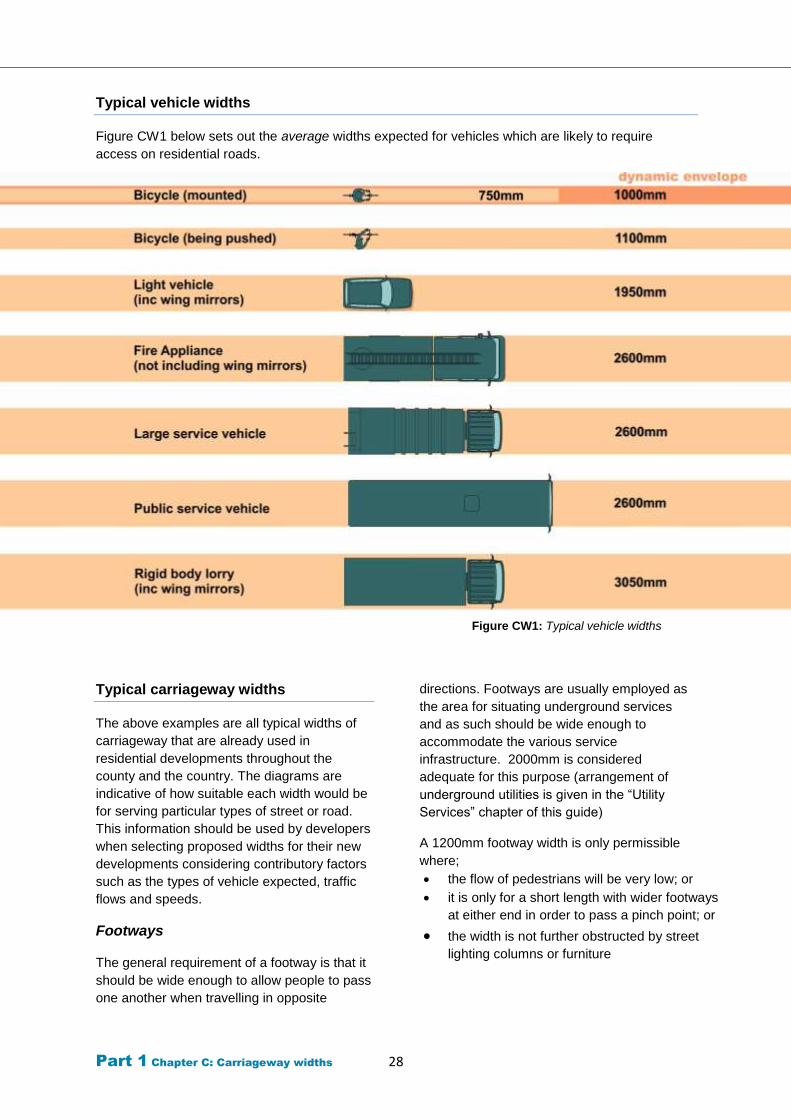
Part 1 Chapter C: Carriageway widths 28
Typical vehicle widths
Figure CW1 below sets out the average widths expected for vehicles which are likely to require
access on residential roads.
Figure CW1: Typical vehicle widths
Typical carriageway widths
The above examples are all typical widths of
carriageway that are already used in
residential developments throughout the
county and the country. The diagrams are
indicative of how suitable each width would be
for serving particular types of street or road.
This information should be used by developers
when selecting proposed widths for their new
developments considering contributory factors
such as the types of vehicle expected, traffic
flows and speeds.
Footways
The general requirement of a footway is that it
should be wide enough to allow people to pass
one another when travelling in opposite
directions. Footways are usually employed as
the area for situating underground services
and as such should be wide enough to
accommodate the various service
infrastructure. 2000mm is considered
adequate for this purpose (arrangement of
underground utilities is given in the “Utility
Services” chapter of this guide)
A 1200mm footway width is only permissible
where;
the flow of pedestrians will be very low; or
it is only for a short length with wider footways
at either end in order to pass a pinch point; or
the width is not further obstructed by street
lighting columns or furniture
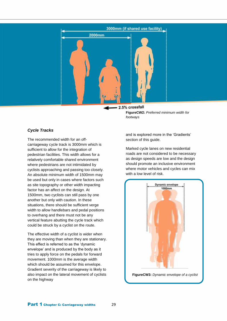
Part 1 Chapter C: Carriageway widths 29
Cycle Tracks
The recommended width for an off-
carriageway cycle track is 3000mm which is
sufficient to allow for the integration of
pedestrian facilities. This width allows for a
relatively comfortable shared environment
where pedestrians are not intimidated by
cyclists approaching and passing too closely.
An absolute minimum width of 1500mm may
be used but only in cases where factors such
as site topography or other width impacting
factor has an affect on the design. At
1500mm, two cyclists can still pass by one
another but only with caution. In these
situations, there should be sufficient verge
width to allow handlebars and pedal positions
to overhang and there must not be any
vertical feature abutting the cycle track which
could be struck by a cyclist on the route.
The effective width of a cyclist is wider when
they are moving than when they are stationary.
This effect is referred to as the ‘dynamic
envelope’ and is produced by the body as it
tries to apply force on the pedals for forward
movement. 1000mm is the average width
which should be assumed for this envelope.
Gradient severity of the carriageway is likely to
also impact on the lateral movement of cyclists
on the highway
FigureCW2: Preferred minimum width for
footways
and is explored more in the ‘Gradients’
section of this guide.
Marked cycle lanes on new residential
roads are not considered to be necessary
as design speeds are low and the design
should promote an inclusive environment
where motor vehicles and cycles can mix
with a low level of risk.
FigureCW3: Dynamic envelope of a cyclist
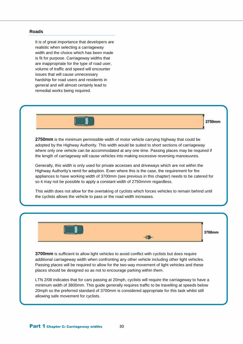
Part 1 Chapter C: Carriageway widths 30
Roads
It is of great importance that developers are
realistic when selecting a carriageway
width and the choice which has been made
is fit for purpose. Carriageway widths that
are inappropriate for the type of road user,
volume of traffic and speed will encounter
issues that will cause unnecessary
hardship for road users and residents in
general and will almost certainly lead to
remedial works being required.
2750mm is the minimum permissible width of motor vehicle carrying highway that could be
adopted by the Highway Authority. This width would be suited to short sections of carriageway
where only one vehicle can be accommodated at any one time. Passing places may be required if
the length of carriageway will cause vehicles into making excessive reversing manoeuvres.
Generally, this width is only used for private accesses and driveways which are not within the
Highway Authority’s remit for adoption. Even where this is the case, the requirement for fire
appliances to have working width of 3700mm (see previous in this chapter) needs to be catered for
so it may not be possible to apply a constant width of 2750mmm regardless.
This width does not allow for the overtaking of cyclists which forces vehicles to remain behind until
the cyclists allows the vehicle to pass or the road width increases.
3700mm is sufficient to allow light vehicles to avoid conflict with cyclists but does require
additional carriageway width when confronting any other vehicle including other light vehicles.
Passing places will be required to allow for the two-way movement of light vehicles and these
places should be designed so as not to encourage parking within them.
LTN 2/08 indicates that for cars passing at 20mph, cyclists will require the carriageway to have a
minimum width of 3800mm. This guide generally requires traffic to be travelling at speeds below
20mph so the preferred standard of 3700mm is considered appropriate for this task whilst still
allowing safe movement for cyclists.
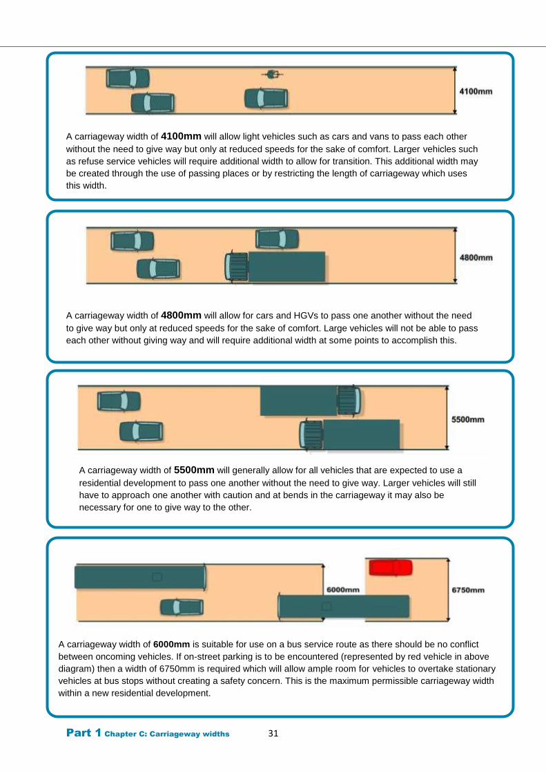
Part 1 Chapter C: Carriageway widths 31
A carriageway width of 6000mm is suitable for use on a bus service route as there should be no conflict
between oncoming vehicles. If on-street parking is to be encountered (represented by red vehicle in above
diagram) then a width of 6750mm is required which will allow ample room for vehicles to overtake stationary
vehicles at bus stops without creating a safety concern. This is the maximum permissible carriageway width
within a new residential development.
A carriageway width of 4100mm will allow light vehicles such as cars and vans to pass each other
without the need to give way but only at reduced speeds for the sake of comfort. Larger vehicles such
as refuse service vehicles will require additional width to allow for transition. This additional width may
be created through the use of passing places or by restricting the length of carriageway which uses
this width.
A carriageway width of 4800mm will allow for cars and HGVs to pass one another without the need
to give way but only at reduced speeds for the sake of comfort. Large vehicles will not be able to pass
each other without giving way and will require additional width at some points to accomplish this.
A carriageway width of 5500mm will generally allow for all vehicles that are expected to use a
residential development to pass one another without the need to give way. Larger vehicles will still
have to approach one another with caution and at bends in the carriageway it may also be
necessary for one to give way to the other.

Part 1 Chapter C: Carriageway widths 32
The ‘Road hierarchy’ chapter of this guide
gives recommended widths for carriageways
serving a variety of street types and should be
seen as a starting point for design decisions
concerning width. Any departures away from
those recommendations will need to be
justified by the provision of evidence to
persuade that the street will still function
efficiently.
Entry points to any road with two-way traffic
should be wide enough at that point to allow
two cars to pass by one another.
Access by emergency services
There are a variety of widths for fire appliances
being used in the UK, however a typical
vehicle width of 2550mm is acceptable for
assessment purposes. This width does not
take into account the wing mirrors of the
vehicle. It is therefore important that this width
can be kept free from obstructions at all times
so that access can be provided to residential
properties.
This does not require that the carriageway
design must permit two vehicles to pass by
one another at all points, rather that where
carriageway width is only one lane wide,
parking must be discouraged.
There is a stated desired minimum width
between kerbs of 3.7m (Association of Chief
Fire Officers) to allow for operating space at a
scene.
It is a regulation within the UK that a fire
appliance must be able to access to a point
within 45m of any dwelling, although this
access does not have to be provided by the
carriageway.
Footpaths or Cycle Track s which are
constructed to a sufficient width and strength
may be considered as suitable emergency
vehicle access (EVA) routes which fire
appliances may utilise to achieve the 45m
access arrangement to a dwelling.
Restricting the length of the narrow section of
carriageway introduces a speed reduction
feature into the development whilst still
allowing access to the maximum required
width vehicle.
It is imperative that developers demonstrate
the arrangements that are in place for
emergency vehicle access in the event of
closures on roads within the development as
well as access to fire hydrants. Permeability
within the design should allow alternate routes
in such situations.
The Highway Authority requires the
provision of an EVA for developments that
contain a minimum of 50 dwellings.
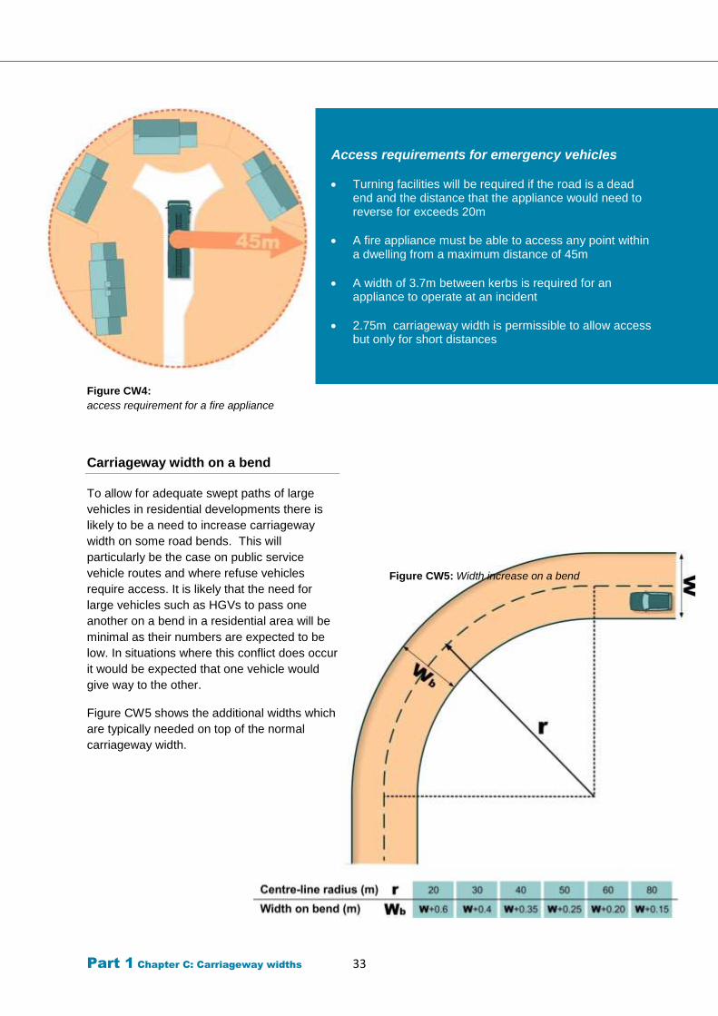
Part 1 Chapter C: Carriageway widths 33
Figure CW4:
access requirement for a fire appliance
Carriageway width on a bend
To allow for adequate swept paths of large
vehicles in residential developments there is
likely to be a need to increase carriageway
width on some road bends. This will
particularly be the case on public service
vehicle routes and where refuse vehicles
require access. It is likely that the need for
large vehicles such as HGVs to pass one
another on a bend in a residential area will be
minimal as their numbers are expected to be
low. In situations where this conflict does occur
it would be expected that one vehicle would
give way to the other.
Figure CW5 shows the additional widths which
are typically needed on top of the normal
carriageway width.
Figure CW5: Width increase on a bend
Access requirements for emergency vehicles
Turning facilities will be required if the road is a dead end and the distance that the appliance would need to reverse for exceeds 20m
A fire appliance must be able to access any point within a dwelling from a maximum distance of 45m
A width of 3.7m between kerbs is required for an appliance to operate at an incident
2.75m carriageway width is permissible to allow access but only for short distances
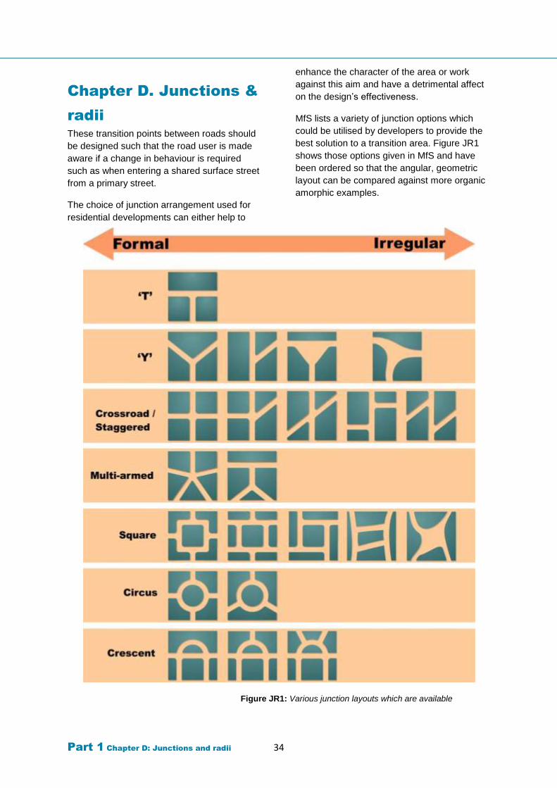
Part 1 Chapter D: Junctions and radii 34
Chapter D. Junctions &
radii
These transition points between roads should
be designed such that the road user is made
aware if a change in behaviour is required
such as when entering a shared surface street
from a primary street.
The choice of junction arrangement used for
residential developments can either help to
enhance the character of the area or work
against this aim and have a detrimental affect
on the design’s effectiveness.
MfS lists a variety of junction options which
could be utilised by developers to provide the
best solution to a transition area. Figure JR1
shows those options given in MfS and have
been ordered so that the angular, geometric
layout can be compared against more organic
amorphic examples.
Figure JR1: Various junction layouts which are available
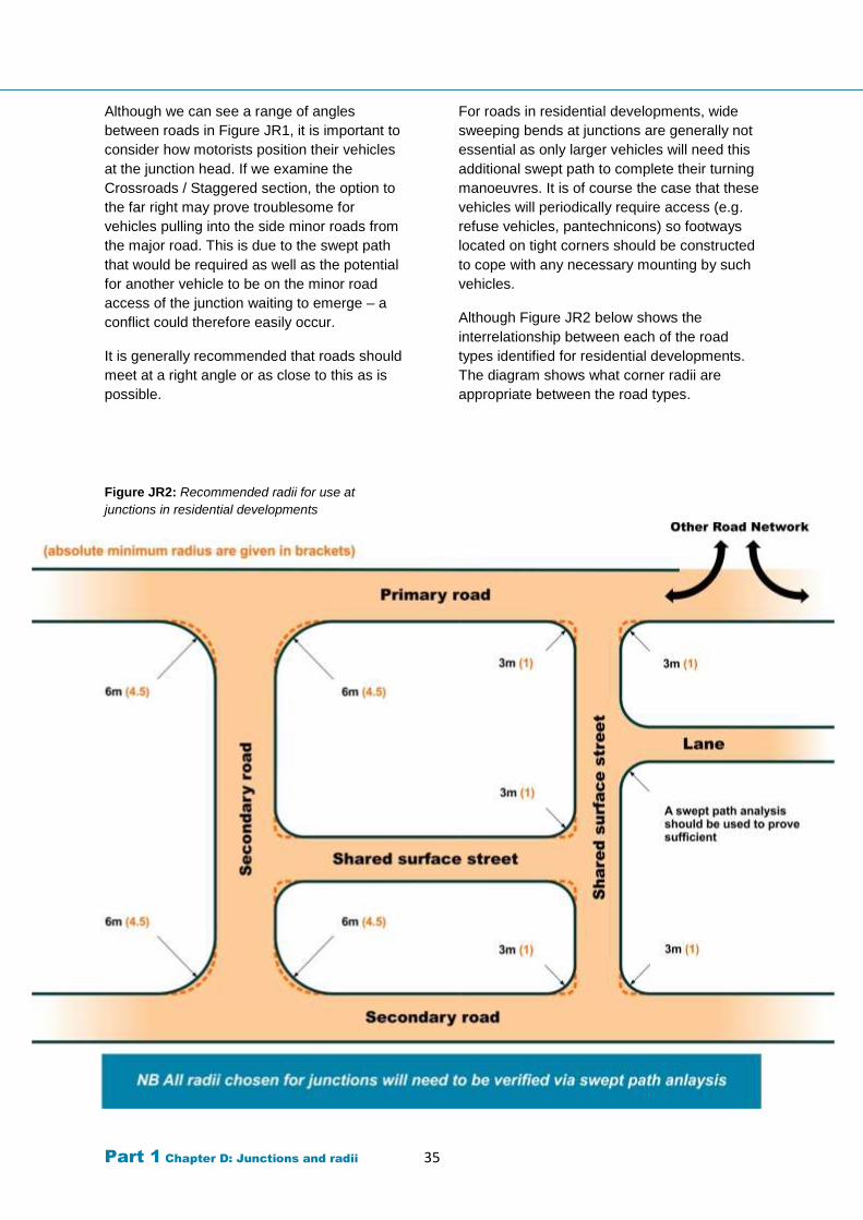
Part 1 Chapter D: Junctions and radii 35
Although we can see a range of angles
between roads in Figure JR1, it is important to
consider how motorists position their vehicles
at the junction head. If we examine the
Crossroads / Staggered section, the option to
the far right may prove troublesome for
vehicles pulling into the side minor roads from
the major road. This is due to the swept path
that would be required as well as the potential
for another vehicle to be on the minor road
access of the junction waiting to emerge – a
conflict could therefore easily occur.
It is generally recommended that roads should
meet at a right angle or as close to this as is
possible.
Figure JR2: Recommended radii for use at
junctions in residential developments
For roads in residential developments, wide
sweeping bends at junctions are generally not
essential as only larger vehicles will need this
additional swept path to complete their turning
manoeuvres. It is of course the case that these
vehicles will periodically require access (e.g.
refuse vehicles, pantechnicons) so footways
located on tight corners should be constructed
to cope with any necessary mounting by such
vehicles.
Although Figure JR2 below shows the
interrelationship between each of the road
types identified for residential developments.
The diagram shows what corner radii are
appropriate between the road types.
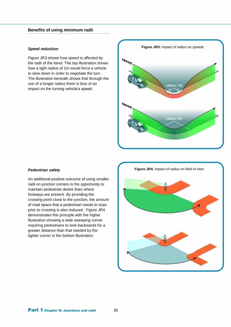
Part 1 Chapter D: Junctions and radii 36
Benefits of using minimum radii
Speed reduction
Figure JR3 shows how speed is affected by
the radii of the bend. The top illustration shows
how a tight radius of 1m would force a vehicle
to slow down in order to negotiate the turn.
The illustration beneath shows that through the
use of a longer radius there is less of an
impact on the turning vehicle’s speed.
Pedestrian safety
An additional positive outcome of using smaller
radii on junction corners is the opportunity to
maintain pedestrian desire lines where
footways are present. By providing the
crossing point close to the junction, the amount
of road space that a pedestrian needs to scan
prior to crossing is also reduced. Figure JR4
demonstrates this principle with the higher
illustration showing a wide sweeping corner
requiring pedestrians to look backwards for a
greater distance than that needed by the
tighter corner in the bottom illustration.
Figure JR3: Impact of radius on speeds
Figure JR4: Impact of radius on field of view
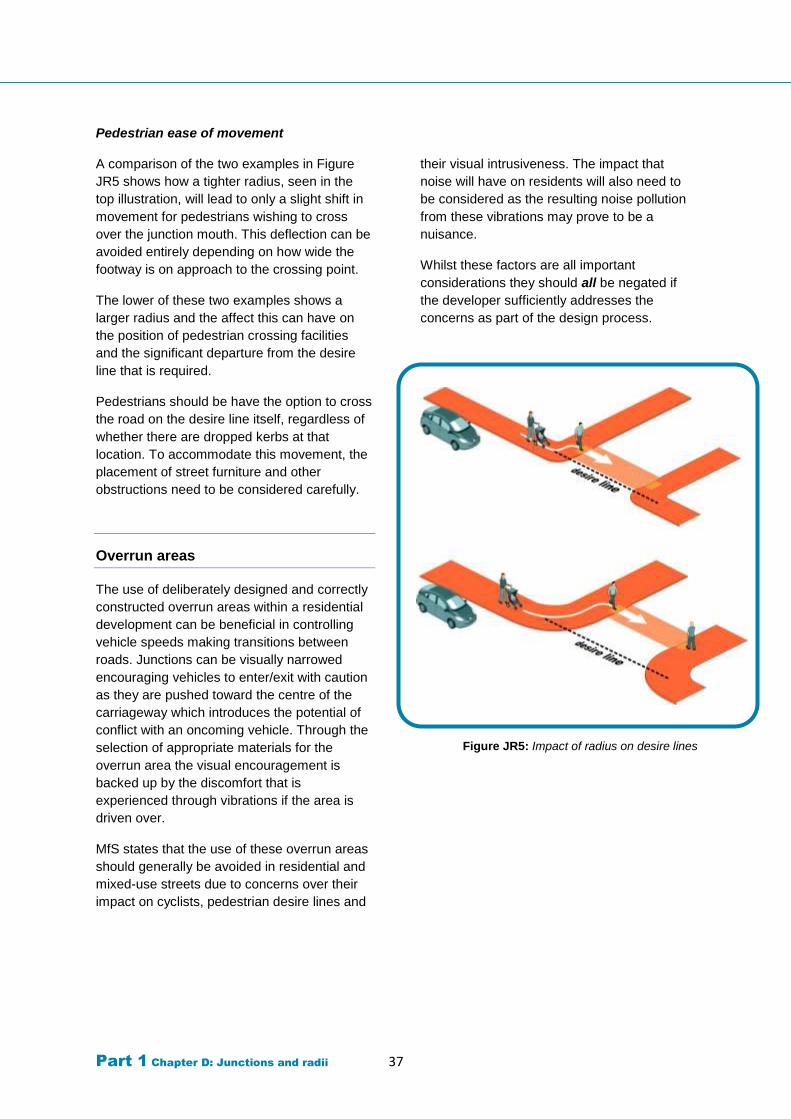
Part 1 Chapter D: Junctions and radii 37
Pedestrian ease of movement
A comparison of the two examples in Figure
JR5 shows how a tighter radius, seen in the
top illustration, will lead to only a slight shift in
movement for pedestrians wishing to cross
over the junction mouth. This deflection can be
avoided entirely depending on how wide the
footway is on approach to the crossing point.
The lower of these two examples shows a
larger radius and the affect this can have on
the position of pedestrian crossing facilities
and the significant departure from the desire
line that is required.
Pedestrians should be have the option to cross
the road on the desire line itself, regardless of
whether there are dropped kerbs at that
location. To accommodate this movement, the
placement of street furniture and other
obstructions need to be considered carefully.
Overrun areas
The use of deliberately designed and correctly
constructed overrun areas within a residential
development can be beneficial in controlling
vehicle speeds making transitions between
roads. Junctions can be visually narrowed
encouraging vehicles to enter/exit with caution
as they are pushed toward the centre of the
carriageway which introduces the potential of
conflict with an oncoming vehicle. Through the
selection of appropriate materials for the
overrun area the visual encouragement is
backed up by the discomfort that is
experienced through vibrations if the area is
driven over.
MfS states that the use of these overrun areas
should generally be avoided in residential and
mixed-use streets due to concerns over their
impact on cyclists, pedestrian desire lines and
their visual intrusiveness. The impact that
noise will have on residents will also need to
be considered as the resulting noise pollution
from these vibrations may prove to be a
nuisance.
Whilst these factors are all important
considerations they should all be negated if
the developer sufficiently addresses the
concerns as part of the design process.
Figure JR5: Impact of radius on desire lines
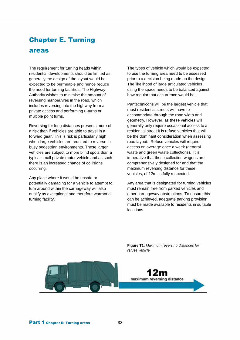
Part 1 Chapter E: Turning areas 38
Chapter E. Turning
areas
The requirement for turning heads within
residential developments should be limited as
generally the design of the layout would be
expected to be permeable and hence reduce
the need for turning facilities. The Highway
Authority wishes to minimise the amount of
reversing manoeuvres in the road, which
includes reversing into the highway from a
private access and performing u-turns or
multiple point turns.
Reversing for long distances presents more of
a risk than if vehicles are able to travel in a
forward gear. This is risk is particularly high
when large vehicles are required to reverse in
busy pedestrian environments. These larger
vehicles are subject to more blind spots than a
typical small private motor vehicle and as such
there is an increased chance of collisions
occurring.
Any place where it would be unsafe or
potentially damaging for a vehicle to attempt to
turn around within the carriageway will also
qualify as exceptional and therefore warrant a
turning facility.
The types of vehicle which would be expected
to use the turning area need to be assessed
prior to a decision being made on the design.
The likelihood of large articulated vehicles
using the space needs to be balanced against
how regular that occurrence would be.
Pantechnicons will be the largest vehicle that
most residential streets will have to
accommodate through the road width and
geometry. However, as these vehicles will
generally only require occasional access to a
residential street it is refuse vehicles that will
be the dominant consideration when assessing
road layout. Refuse vehicles will require
access on average once a week (general
waste and green waste collections). It is
imperative that these collection wagons are
comprehensively designed for and that the
maximum reversing distance for these
vehicles, of 12m, is fully respected.
Any area that is designated for turning vehicles
must remain free from parked vehicles and
other carriageway obstructions. To ensure this
can be achieved, adequate parking provision
must be made available to residents in suitable
locations.
Figure T1: Maximum reversing distances for
refuse vehicle
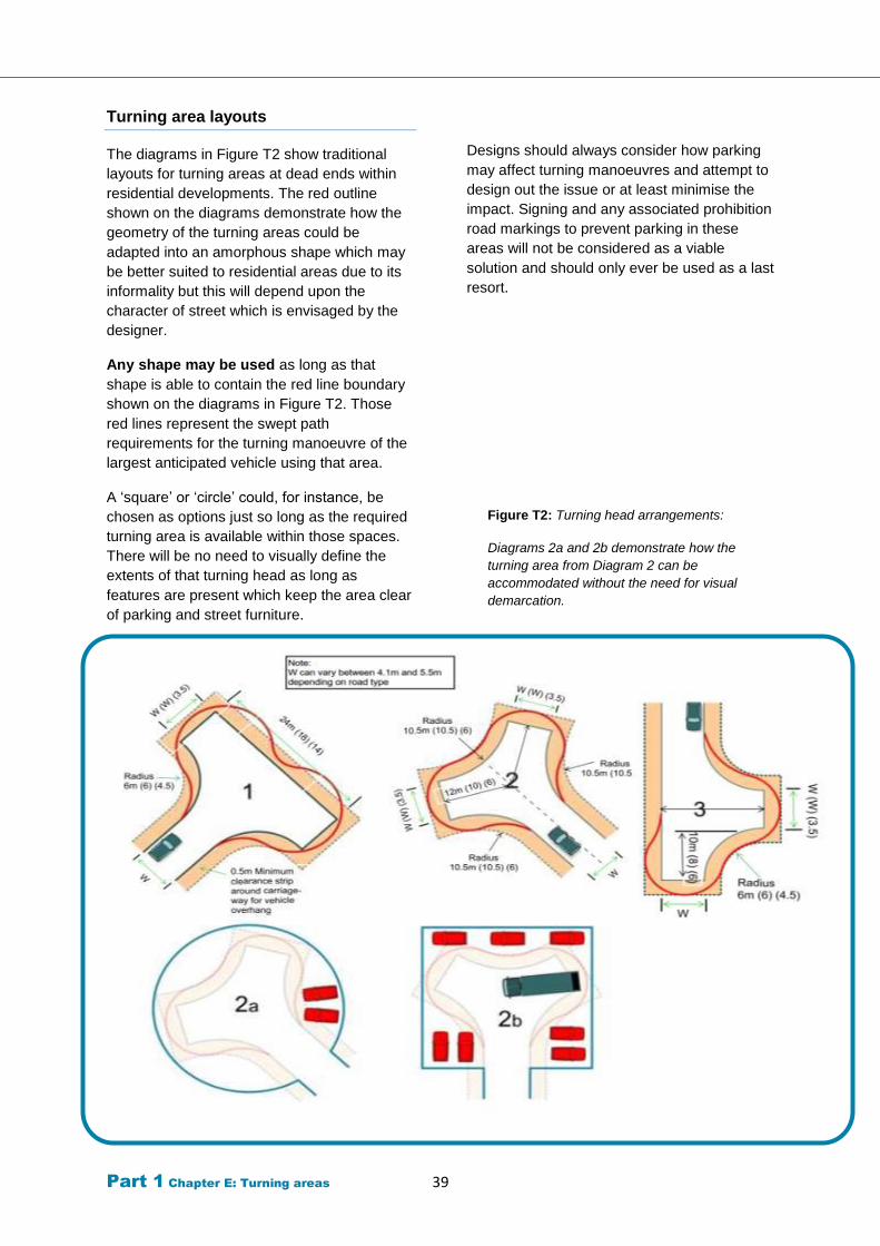
Part 1 Chapter E: Turning areas 39
Turning area layouts
The diagrams in Figure T2 show traditional
layouts for turning areas at dead ends within
residential developments. The red outline
shown on the diagrams demonstrate how the
geometry of the turning areas could be
adapted into an amorphous shape which may
be better suited to residential areas due to its
informality but this will depend upon the
character of street which is envisaged by the
designer.
Any shape may be used as long as that
shape is able to contain the red line boundary
shown on the diagrams in Figure T2. Those
red lines represent the swept path
requirements for the turning manoeuvre of the
largest anticipated vehicle using that area.
A ‘square’ or ‘circle’ could, for instance, be
chosen as options just so long as the required
turning area is available within those spaces.
There will be no need to visually define the
extents of that turning head as long as
features are present which keep the area clear
of parking and street furniture.
Designs should always consider how parking
may affect turning manoeuvres and attempt to
design out the issue or at least minimise the
impact. Signing and any associated prohibition
road markings to prevent parking in these
areas will not be considered as a viable
solution and should only ever be used as a last
resort.
Figure T2: Turning head arrangements:
Diagrams 2a and 2b demonstrate how the
turning area from Diagram 2 can be
accommodated without the need for visual
demarcation.
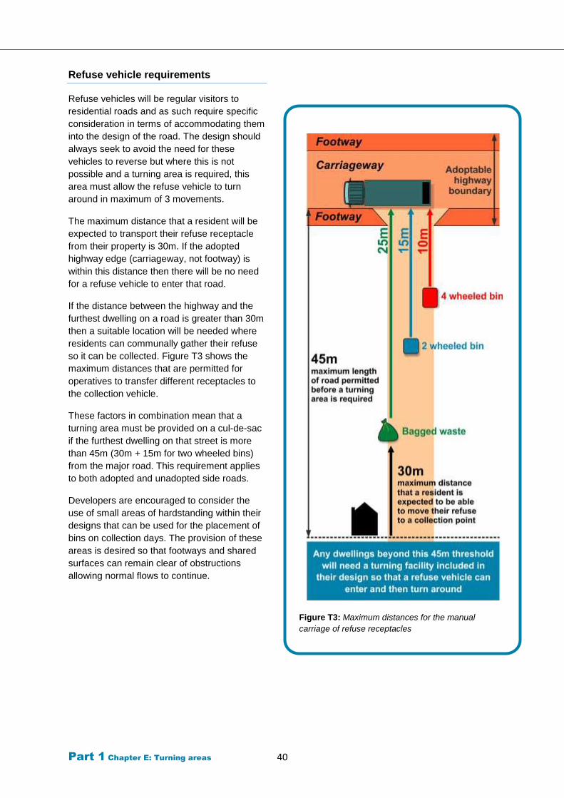
Part 1 Chapter E: Turning areas 40
Refuse vehicle requirements
Refuse vehicles will be regular visitors to
residential roads and as such require specific
consideration in terms of accommodating them
into the design of the road. The design should
always seek to avoid the need for these
vehicles to reverse but where this is not
possible and a turning area is required, this
area must allow the refuse vehicle to turn
around in maximum of 3 movements.
The maximum distance that a resident will be
expected to transport their refuse receptacle
from their property is 30m. If the adopted
highway edge (carriageway, not footway) is
within this distance then there will be no need
for a refuse vehicle to enter that road.
If the distance between the highway and the
furthest dwelling on a road is greater than 30m
then a suitable location will be needed where
residents can communally gather their refuse
so it can be collected. Figure T3 shows the
maximum distances that are permitted for
operatives to transfer different receptacles to
the collection vehicle.
These factors in combination mean that a
turning area must be provided on a cul-de-sac
if the furthest dwelling on that street is more
than 45m (30m + 15m for two wheeled bins)
from the major road. This requirement applies
to both adopted and unadopted side roads.
Developers are encouraged to consider the
use of small areas of hardstanding within their
designs that can be used for the placement of
bins on collection days. The provision of these
areas is desired so that footways and shared
surfaces can remain clear of obstructions
allowing normal flows to continue.
Figure T3: Maximum distances for the manual
carriage of refuse receptacles
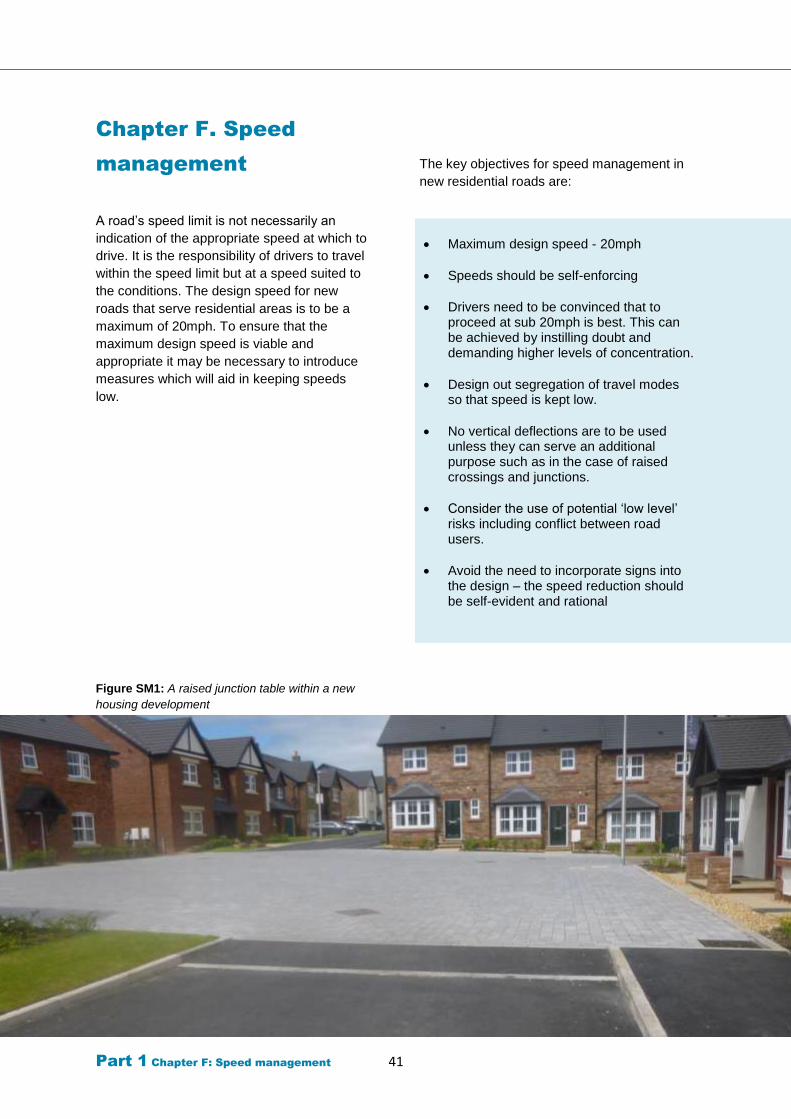
Part 1 Chapter F: Speed management 41
Chapter F. Speed
management
A road’s speed limit is not necessarily an
indication of the appropriate speed at which to
drive. It is the responsibility of drivers to travel
within the speed limit but at a speed suited to
the conditions. The design speed for new
roads that serve residential areas is to be a
maximum of 20mph. To ensure that the
maximum design speed is viable and
appropriate it may be necessary to introduce
measures which will aid in keeping speeds
low.
Figure SM1: A raised junction table within a new
housing development
The key objectives for speed management in
new residential roads are:
Maximum design speed - 20mph
Speeds should be self-enforcing
Drivers need to be convinced that to proceed at sub 20mph is best. This can be achieved by instilling doubt and demanding higher levels of concentration.
Design out segregation of travel modes so that speed is kept low.
No vertical deflections are to be used unless they can serve an additional purpose such as in the case of raised crossings and junctions.
Consider the use of potential ‘low level’ risks including conflict between road users.
Avoid the need to incorporate signs into the design – the speed reduction should be self-evident and rational
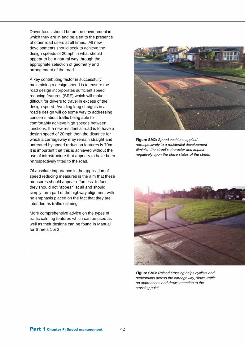
Part 1 Chapter F: Speed management 42
Driver focus should be on the environment in
which they are in and be alert to the presence
of other road users at all times. All new
developments should seek to achieve the
design speeds of 20mph in what should
appear to be a natural way through the
appropriate selection of geometry and
arrangement of the road.
A key contributing factor in successfully
maintaining a design speed is to ensure the
road design incorporates sufficient speed
reducing features (SRF) which will make it
difficult for drivers to travel in excess of the
design speed. Avoiding long straights in a
road’s design will go some way to addressing
concerns about traffic being able to
comfortably achieve high speeds between
junctions. If a new residential road is to have a
design speed of 20mph then the distance for
which a carriageway may remain straight and
untreated by speed reduction features is 70m.
It is important that this is achieved without the
use of infrastructure that appears to have been
retrospectively fitted to the road.
Of absolute importance in the application of
speed reducing measures is the aim that these
measures should appear effortless. In fact,
they should not “appear” at all and should
simply form part of the highway alignment with
no emphasis placed on the fact that they are
intended as traffic calming.
More comprehensive advice on the types of
traffic calming features which can be used as
well as their designs can be found in Manual
for Streets 1 & 2.
.
Figure SM2: Speed cushions applied
retrospectively to a residential development
diminish the street’s character and impact
negatively upon the place status of the street.
Figure SM3: Raised crossing helps cyclists and
pedestrians across the carriageway, slows traffic
on approaches and draws attention to the
crossing point
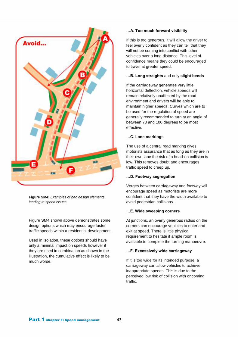
Part 1 Chapter F: Speed management 43
Figure SM4: Examples of bad design elements
leading to speed issues
Figure SM4 shown above demonstrates some
design options which may encourage faster
traffic speeds within a residential development.
Used in isolation, these options should have
only a minimal impact on speeds however if
they are used in combination as shown in the
illustration, the cumulative effect is likely to be
much worse.
…A. Too much forward visibility
If this is too generous, it will allow the driver to
feel overly confident as they can tell that they
will not be coming into conflict with other
vehicles over a long distance. This level of
confidence means they could be encouraged
to travel at greater speed.
…B. Long straights and only slight bends
If the carriageway generates very little
horizontal deflection, vehicle speeds will
remain relatively unaffected by the road
environment and drivers will be able to
maintain higher speeds. Curves which are to
be used for the regulation of speed are
generally recommended to turn at an angle of
between 70 and 100 degrees to be most
effective.
…C. Lane markings
The use of a central road marking gives
motorists assurance that as long as they are in
their own lane the risk of a head-on collision is
low. This removes doubt and encourages
traffic speed to creep up.
…D. Footway segregation
Verges between carriageway and footway will
encourage speed as motorists are more
confident that they have the width available to
avoid pedestrian collisions.
…E. Wide sweeping corners
At junctions, an overly generous radius on the
corners can encourage vehicles to enter and
exit at speed. There is little physical
requirement to hesitate if ample room is
available to complete the turning manoeuvre.
…F. Excessively wide carriageway
If it is too wide for its intended purpose, a
carriageway can allow vehicles to achieve
inappropriate speeds. This is due to the
perceived low risk of collision with oncoming
traffic.
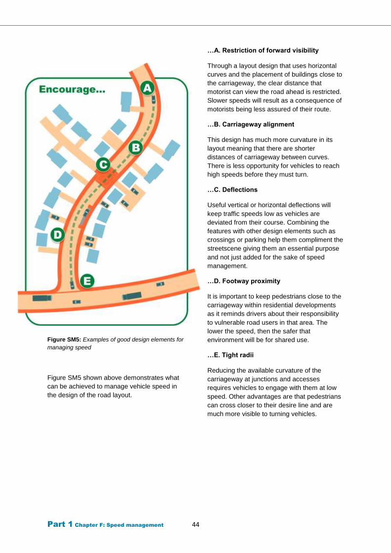
Part 1 Chapter F: Speed management 44
Figure SM5: Examples of good design elements for
managing speed
Figure SM5 shown above demonstrates what
can be achieved to manage vehicle speed in
the design of the road layout.
…A. Restriction of forward visibility
Through a layout design that uses horizontal
curves and the placement of buildings close to
the carriageway, the clear distance that
motorist can view the road ahead is restricted.
Slower speeds will result as a consequence of
motorists being less assured of their route.
…B. Carriageway alignment
This design has much more curvature in its
layout meaning that there are shorter
distances of carriageway between curves.
There is less opportunity for vehicles to reach
high speeds before they must turn.
…C. Deflections
Useful vertical or horizontal deflections will
keep traffic speeds low as vehicles are
deviated from their course. Combining the
features with other design elements such as
crossings or parking help them compliment the
streetscene giving them an essential purpose
and not just added for the sake of speed
management.
…D. Footway proximity
It is important to keep pedestrians close to the
carriageway within residential developments
as it reminds drivers about their responsibility
to vulnerable road users in that area. The
lower the speed, then the safer that
environment will be for shared use.
…E. Tight radii
Reducing the available curvature of the
carriageway at junctions and accesses
requires vehicles to engage with them at low
speed. Other advantages are that pedestrians
can cross closer to their desire line and are
much more visible to turning vehicles.
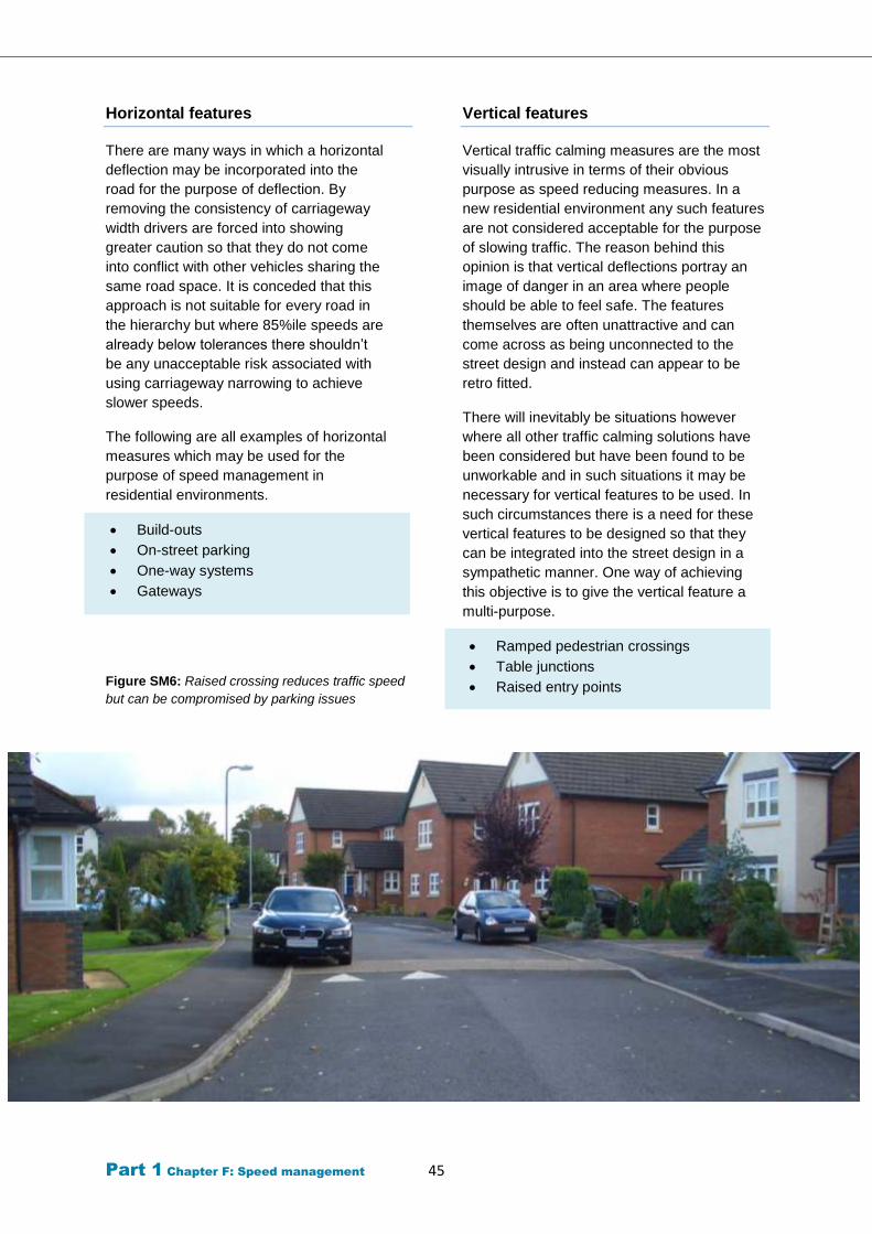
Part 1 Chapter F: Speed management 45
Horizontal features
There are many ways in which a horizontal
deflection may be incorporated into the
road for the purpose of deflection. By
removing the consistency of carriageway
width drivers are forced into showing
greater caution so that they do not come
into conflict with other vehicles sharing the
same road space. It is conceded that this
approach is not suitable for every road in
the hierarchy but where 85%ile speeds are
already below tolerances there shouldn’t
be any unacceptable risk associated with
using carriageway narrowing to achieve
slower speeds.
The following are all examples of horizontal
measures which may be used for the
purpose of speed management in
residential environments.
Build-outs
On-street parking
One-way systems
Gateways
Figure SM6: Raised crossing reduces traffic speed
but can be compromised by parking issues
Vertical features
Vertical traffic calming measures are the most
visually intrusive in terms of their obvious
purpose as speed reducing measures. In a
new residential environment any such features
are not considered acceptable for the purpose
of slowing traffic. The reason behind this
opinion is that vertical deflections portray an
image of danger in an area where people
should be able to feel safe. The features
themselves are often unattractive and can
come across as being unconnected to the
street design and instead can appear to be
retro fitted.
There will inevitably be situations however
where all other traffic calming solutions have
been considered but have been found to be
unworkable and in such situations it may be
necessary for vertical features to be used. In
such circumstances there is a need for these
vertical features to be designed so that they
can be integrated into the street design in a
sympathetic manner. One way of achieving
this objective is to give the vertical feature a
multi-purpose.
Ramped pedestrian crossings
Table junctions
Raised entry points
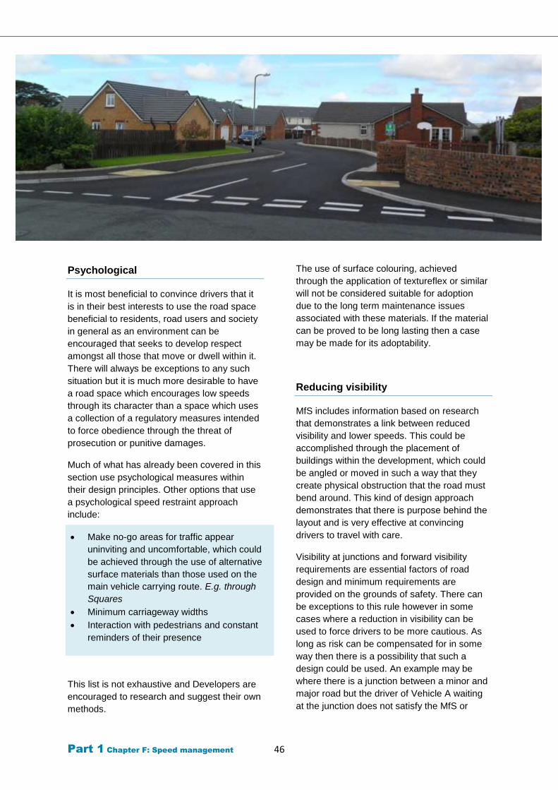
Part 1 Chapter F: Speed management 46
Psychological
It is most beneficial to convince drivers that it
is in their best interests to use the road space
beneficial to residents, road users and society
in general as an environment can be
encouraged that seeks to develop respect
amongst all those that move or dwell within it.
There will always be exceptions to any such
situation but it is much more desirable to have
a road space which encourages low speeds
through its character than a space which uses
a collection of a regulatory measures intended
to force obedience through the threat of
prosecution or punitive damages.
Much of what has already been covered in this
section use psychological measures within
their design principles. Other options that use
a psychological speed restraint approach
include:
Make no-go areas for traffic appear
uninviting and uncomfortable, which could
be achieved through the use of alternative
surface materials than those used on the
main vehicle carrying route. E.g. through
Squares
Minimum carriageway widths
Interaction with pedestrians and constant
reminders of their presence
This list is not exhaustive and Developers are
encouraged to research and suggest their own
methods.
The use of surface colouring, achieved
through the application of textureflex or similar
will not be considered suitable for adoption
due to the long term maintenance issues
associated with these materials. If the material
can be proved to be long lasting then a case
may be made for its adoptability.
Reducing visibility
MfS includes information based on research
that demonstrates a link between reduced
visibility and lower speeds. This could be
accomplished through the placement of
buildings within the development, which could
be angled or moved in such a way that they
create physical obstruction that the road must
bend around. This kind of design approach
demonstrates that there is purpose behind the
layout and is very effective at convincing
drivers to travel with care.
Visibility at junctions and forward visibility
requirements are essential factors of road
design and minimum requirements are
provided on the grounds of safety. There can
be exceptions to this rule however in some
cases where a reduction in visibility can be
used to force drivers to be more cautious. As
long as risk can be compensated for in some
way then there is a possibility that such a
design could be used. An example may be
where there is a junction between a minor and
major road but the driver of Vehicle A waiting
at the junction does not satisfy the MfS or
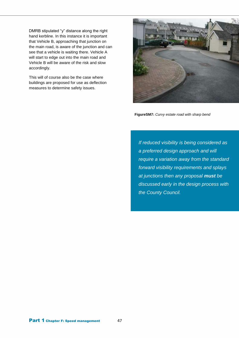
Part 1 Chapter F: Speed management 47
DMRB stipulated “y” distance along the right
hand kerbline. In this instance it is important
that Vehicle B, approaching that junction on
the main road, is aware of the junction and can
see that a vehicle is waiting there. Vehicle A
will start to edge out into the main road and
Vehicle B will be aware of the risk and slow
accordingly.
This will of course also be the case where
buildings are proposed for use as deflection
measures to determine safety issues.
FigureSM7: Curvy estate road with sharp bend
If reduced visibility is being considered as
a preferred design approach and will
require a variation away from the standard
forward visibility requirements and splays
at junctions then any proposal must be
discussed early in the design process with
the County Council.
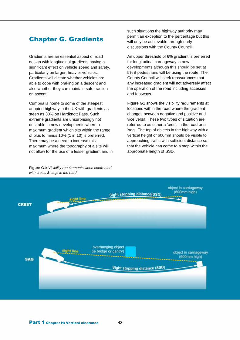
Part 1 Chapter H: Vertical clearance 48
Chapter G. Gradients
Gradients are an essential aspect of road
design with longitudinal gradients having a
significant effect on vehicle speed and safety,
particularly on larger, heavier vehicles.
Gradients will dictate whether vehicles are
able to cope with braking on a descent and
also whether they can maintain safe traction
on ascent.
Cumbria is home to some of the steepest
adopted highway in the UK with gradients as
steep as 30% on Hardknott Pass. Such
extreme gradients are unsurprisingly not
desirable in new developments where a
maximum gradient which sits within the range
of plus to minus 10% (1 in 10) is preferred.
There may be a need to increase this
maximum where the topography of a site will
not allow for the use of a lesser gradient and in
such situations the highway authority may
permit an exception to the percentage but this
will only be achievable through early
discussions with the County Council.
An upper threshold of 6% gradient is preferred
for longitudinal carriageway in new
developments although this should be set at
5% if pedestrians will be using the route. The
County Council will seek reassurances that
any increased gradient will not adversely affect
the operation of the road including accesses
and footways.
Figure G1 shows the visibility requirements at
locations within the road where the gradient
changes between negative and positive and
vice versa. These two types of situation are
referred to as either a ‘crest’ in the road or a
‘sag’. The top of objects in the highway with a
vertical height of 600mm should be visible to
approaching traffic with sufficient distance so
that the vehicle can come to a stop within the
appropriate length of SSD.
Figure G1: Visibility requirements when confronted
with crests & sags in the road
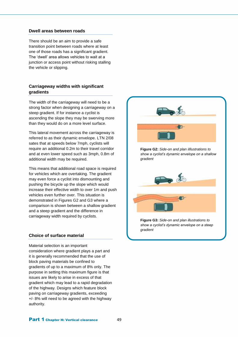
Part 1 Chapter H: Vertical clearance 49
Dwell areas between roads
There should be an aim to provide a safe
transition point between roads where at least
one of those roads has a significant gradient.
The ‘dwell’ area allows vehicles to wait at a
junction or access point without risking stalling
the vehicle or slipping.
Carriageway widths with significant
gradients
The width of the carriageway will need to be a
strong factor when designing a carriageway on a
steep gradient. If for instance a cyclist is
ascending the slope they may be swerving more
than they would do on a more level surface.
This lateral movement across the carriageway is
referred to as their dynamic envelope. LTN 2/08
sates that at speeds below 7mph, cyclists will
require an additional 0.2m to their travel corridor
and at even lower speed such as 3mph, 0.8m of
additional width may be required.
This means that additional road space is required
for vehicles which are overtaking. The gradient
may even force a cyclist into dismounting and
pushing the bicycle up the slope which would
increase their effective width to over 1m and push
vehicles even further over. This situation is
demonstrated in Figures G2 and G3 where a
comparison is shown between a shallow gradient
and a steep gradient and the difference in
carriageway width required by cyclists.
Choice of surface material
Material selection is an important
consideration where gradient plays a part and
it is generally recommended that the use of
block paving materials be confined to
gradients of up to a maximum of 8% only. The
purpose in setting this maximum figure is that
issues are likely to arise in excess of that
gradient which may lead to a rapid degradation
of the highway. Designs which feature block
paving on carriageway gradients, exceeding
+/- 8% will need to be agreed with the highway
authority.
Figure G2: Side-on and plan iIllustrations to
show a cyclist’s dynamic envelope on a shallow
gradient
Figure G3: Side-on and plan illustrations to
show a cyclist’s dynamic envelope on a steep
gradient
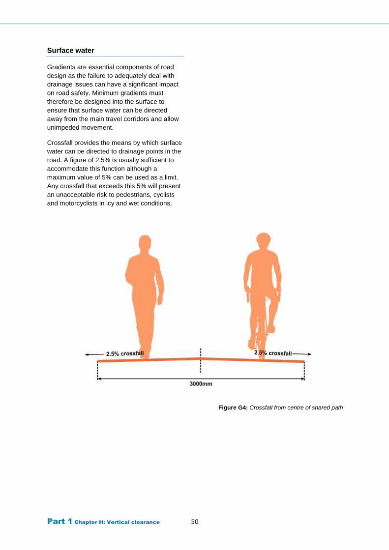
Part 1 Chapter H: Vertical clearance 50
Surface water
Gradients are essential components of road
design as the failure to adequately deal with
drainage issues can have a significant impact
on road safety. Minimum gradients must
therefore be designed into the surface to
ensure that surface water can be directed
away from the main travel corridors and allow
unimpeded movement.
Crossfall provides the means by which surface
water can be directed to drainage points in the
road. A figure of 2.5% is usually sufficient to
accommodate this function although a
maximum value of 5% can be used as a limit.
Any crossfall that exceeds this 5% will present
an unacceptable risk to pedestrians, cyclists
and motorcyclists in icy and wet conditions.
Figure G4: Crossfall from centre of shared path
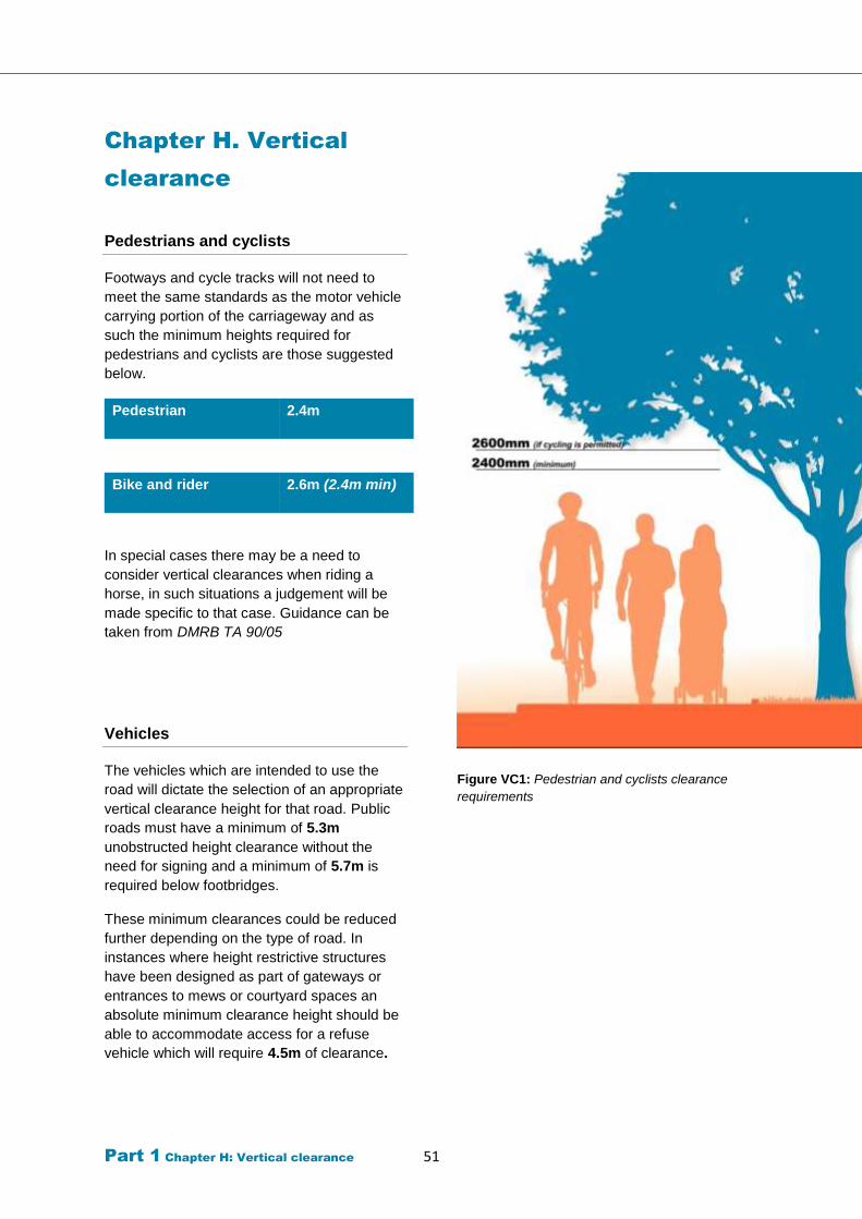
Part 1 Chapter H: Vertical clearance 51
Chapter H. Vertical
clearance
Pedestrians and cyclists
Footways and cycle tracks will not need to
meet the same standards as the motor vehicle
carrying portion of the carriageway and as
such the minimum heights required for
pedestrians and cyclists are those suggested
below.
Pedestrian 2.4m
Bike and rider 2.6m (2.4m min)
In special cases there may be a need to
consider vertical clearances when riding a
horse, in such situations a judgement will be
made specific to that case. Guidance can be
taken from DMRB TA 90/05
Vehicles
The vehicles which are intended to use the
road will dictate the selection of an appropriate
vertical clearance height for that road. Public
roads must have a minimum of 5.3m
unobstructed height clearance without the
need for signing and a minimum of 5.7m is
required below footbridges.
These minimum clearances could be reduced
further depending on the type of road. In
instances where height restrictive structures
have been designed as part of gateways or
entrances to mews or courtyard spaces an
absolute minimum clearance height should be
able to accommodate access for a refuse
vehicle which will require 4.5m of clearance.
Figure VC1: Pedestrian and cyclists clearance
requirements
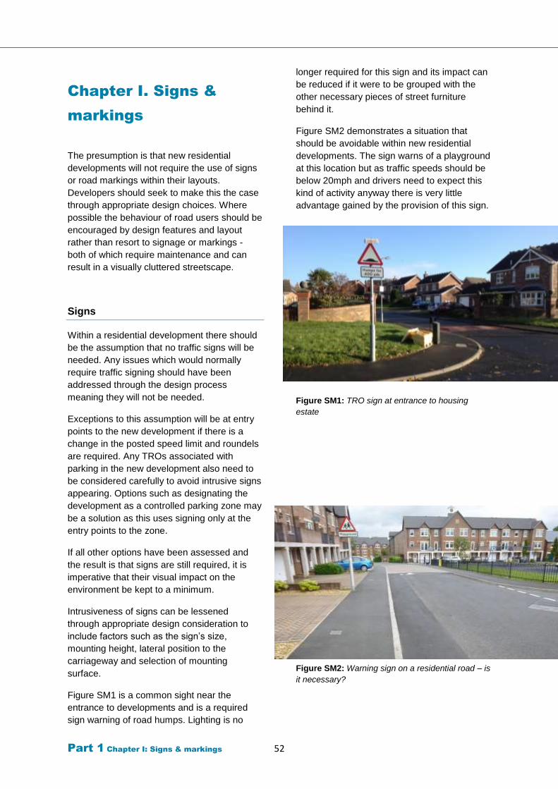
Part 1 Chapter I: Signs & markings 52
Chapter I. Signs &
markings
The presumption is that new residential
developments will not require the use of signs
or road markings within their layouts.
Developers should seek to make this the case
through appropriate design choices. Where
possible the behaviour of road users should be
encouraged by design features and layout
rather than resort to signage or markings -
both of which require maintenance and can
result in a visually cluttered streetscape.
Signs
Within a residential development there should
be the assumption that no traffic signs will be
needed. Any issues which would normally
require traffic signing should have been
addressed through the design process
meaning they will not be needed.
Exceptions to this assumption will be at entry
points to the new development if there is a
change in the posted speed limit and roundels
are required. Any TROs associated with
parking in the new development also need to
be considered carefully to avoid intrusive signs
appearing. Options such as designating the
development as a controlled parking zone may
be a solution as this uses signing only at the
entry points to the zone.
If all other options have been assessed and
the result is that signs are still required, it is
imperative that their visual impact on the
environment be kept to a minimum.
Intrusiveness of signs can be lessened
through appropriate design consideration to
include factors such as the sign’s size,
mounting height, lateral position to the
carriageway and selection of mounting
surface.
Figure SM1 is a common sight near the
entrance to developments and is a required
sign warning of road humps. Lighting is no
longer required for this sign and its impact can
be reduced if it were to be grouped with the
other necessary pieces of street furniture
behind it.
Figure SM2 demonstrates a situation that
should be avoidable within new residential
developments. The sign warns of a playground
at this location but as traffic speeds should be
below 20mph and drivers need to expect this
kind of activity anyway there is very little
advantage gained by the provision of this sign.
Figure SM1: TRO sign at entrance to housing
estate
Figure SM2: Warning sign on a residential road – is
it necessary?
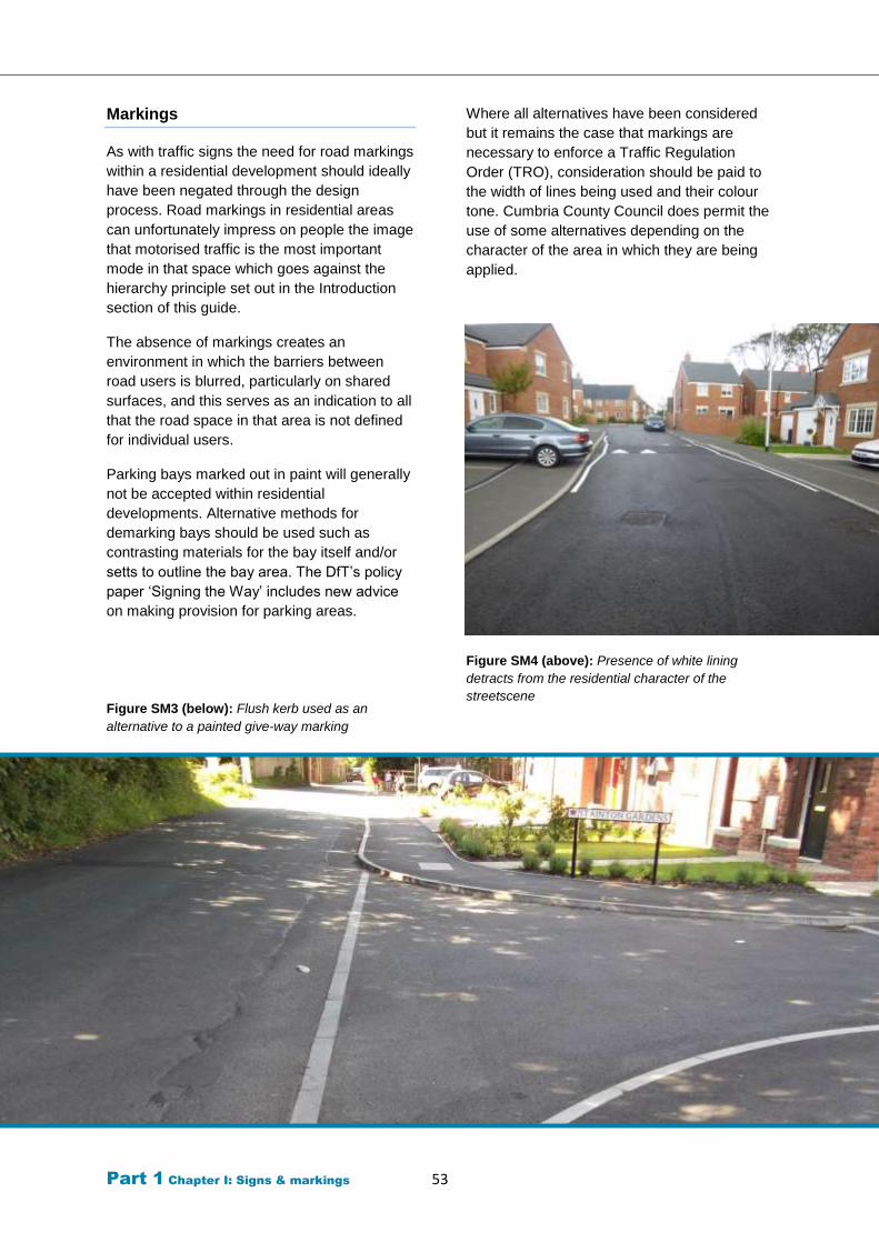
Part 1 Chapter I: Signs & markings 53
Markings
As with traffic signs the need for road markings
within a residential development should ideally
have been negated through the design
process. Road markings in residential areas
can unfortunately impress on people the image
that motorised traffic is the most important
mode in that space which goes against the
hierarchy principle set out in the Introduction
section of this guide.
The absence of markings creates an
environment in which the barriers between
road users is blurred, particularly on shared
surfaces, and this serves as an indication to all
that the road space in that area is not defined
for individual users.
Parking bays marked out in paint will generally
not be accepted within residential
developments. Alternative methods for
demarking bays should be used such as
contrasting materials for the bay itself and/or
setts to outline the bay area. The DfT’s policy
paper ‘Signing the Way’ includes new advice
on making provision for parking areas.
Figure SM3 (below): Flush kerb used as an
alternative to a painted give-way marking
Where all alternatives have been considered
but it remains the case that markings are
necessary to enforce a Traffic Regulation
Order (TRO), consideration should be paid to
the width of lines being used and their colour
tone. Cumbria County Council does permit the
use of some alternatives depending on the
character of the area in which they are being
applied.
Figure SM4 (above): Presence of white lining
detracts from the residential character of the
streetscene
Part 1 Chapter J: Parking 54
Chapter J. Parking
This guidance replaces the
Parking Guidelines in Cumbria
(1997)
Parking is essential to the success or
otherwise of a residential development. If
managed correctly, the environment will be
one where stationary vehicles can be
accommodated whilst still allowing for other
road users to carry on with their business
unhindered or at least only minor
inconvenience. The problems that occur if
parking is not sufficiently designed for can
soon escalate into major issues that
compromise not only the efficiency of the
highway network but the safety and living
standards of residents.
The main issues that arise from residential
parking include:
Obstructions to pedestrian movement
This occurs where vehicles are parked partially
or wholly upon the footway. The result is that
pedestrians are forced into entering the live
carriageway, a situation which is not always
easily achievable for those with mobility
impairments or visual impairment.
Barrier to free movement of emergency
vehicles in the course of their duties
Pinch-points created by badly parked vehicles
could prevent fire appliances from accessing
an emergency situation. Due consideration
needs to be given by the developer as to how
access can be maintained.
Obstructions to private driveways and
property
Annoyance can be generated in residents
where inappropriately parked vehicles block
access arrangements to dwellings.
Congestion on bus and refuse vehicle
routes
If parking takes place at potential choke points
within the development there may occur
instances where routes become impassable by
large vehicles. Buses and refuse vehicles can
find their paths blocked which forces them into
manoeuvres that present risk to the vehicle
and others within the road.
Damage is inflicted on footways and verges
Footways and kerbs that have not been
selected with vehicle mounting movements in
mind will deteriorate quicker than the intended
design life of the surface. These surfaces must
be constructed to the appropriate standard or
the design must prevent parking in such areas.
Grass verges are often left open to abuse from
parking as they are seen by many as excess
surfacing, useless and good for nothing else
other than parking. The over-run of these
verges damages the turf and results in
unattractive, maintenance intensive, unsafe
part of the highway.
The character of the development is
tarnished by excessive parking
The extent to which vehicles are parked in a
residential area will have a significant input
into how people are able to navigate the
space. When vehicles are parked between
buildings and the carriageway the impression
is one of the car being the main priority in that
space. This is something that the guidance
strongly wishes to challenge as pedestrians
must be the priority in new developments.
Pressures on the amount of parking space
available may encourage some homeowners
to create additional parking within their
curtilage by converting landscaped areas in
hardstanding (and sometimes not even that).
Parking should be designed so it does not
detract from visual amenities of the area. The
use of different type of surfaces e.g.
grasscrete and landscaping should be
considered.
Part 1 Chapter J: Parking 55
Parking numbers
Planning applications are determined in
accordance with the Development Plan (the
Local Planning Authority’s adopted policies)
unless material considerations indicate
otherwise. Material considerations can include
national planning policy as set out in the
National Planning Policy Framework,
Government policy as set out in ministerial
statements, or site specific circumstances.
The guidance is provided to support Local
Planning Authorities in assessing the potential
impacts of development on a site by site basis
within the context of the Development Plan,
site specific considerations, and other material
considerations (such as national
policy). Developments may prove acceptable
without offering parking levels as indicated
below, or prove unacceptable despite offering
parking levels equal to or greater than those
indicated, depending on the circumstances.
Guidance on parking numbers
can be found in Appendix 1
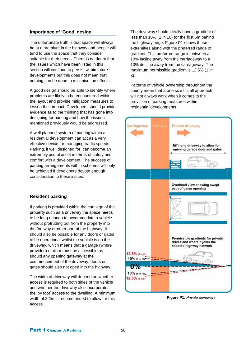
Part 1 Chapter J: Parking 56
Importance of ‘Good’ design
The unfortunate truth is that space will always
be at a premium in the highway and people will
tend to use the space that they consider
suitable for their needs. There is no doubt that
the issues which have been listed in this
section will continue to persist within future
developments but this does not mean that
nothing can be done to minimise the effects.
A good design should be able to identify where
problems are likely to be encountered within
the layout and provide mitigation measures to
lessen their impact. Developers should provide
evidence as to the thinking that has gone into
designing for parking and how the issues
mentioned previously would be addressed.
A well planned system of parking within a
residential development can act as a very
effective device for managing traffic speeds.
Parking, if well designed for, can become an
extremely useful asset in terms of safety and
comfort with a development. The success of
parking arrangements within schemes will only
be achieved if developers devote enough
consideration to these issues.
Resident parking
If parking is provided within the curtilage of the
property such as a driveway the space needs
to be long enough to accommodate a vehicle
without protruding out from the property into
the footway or other part of the highway. It
should also be possible for any doors or gates
to be operational whilst the vehicle is on the
driveway, which means that a garage (where
provided) or door must be accessible as
should any opening gateway at the
commencement of the driveway, doors or
gates should also not open into the highway.
The width of driveway will depend on whether
access is required to both sides of the vehicle
and whether the driveway also incorporates
the ‘by foot’ access to the dwelling. A minimum
width of 3.2m is recommended to allow for this
access.
The driveway should ideally have a gradient of
less than 10% (1 in 10) for the first 6m behind
the highway edge. Figure P1 shows these
extremities along with the preferred range of
gradient. This preferred range is between a
10% incline away from the carriageway to a
10% decline away from the carriageway. The
maximum permissible gradient is 12.5% (1 in
8).
Patterns of vehicle ownership throughout the
county mean that a one size fits all approach
will not always work when it comes to the
provision of parking measures within
residential developments.
Figure P1: Private driveways
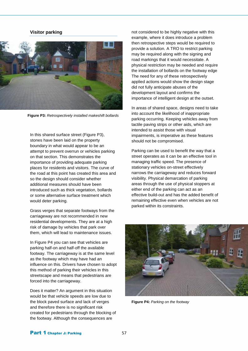
Part 1 Chapter J: Parking 57
Visitor parking
Figure P3: Retrospectively installed makeshift bollards
In this shared surface street (Figure P3),
stones have been laid on the property
boundary in what would appear to be an
attempt to prevent overrun or vehicles parking
on that section. This demonstrates the
importance of providing adequate parking
places for residents and visitors. The curve of
the road at this point has created this area and
so the design should consider whether
additional measures should have been
introduced such as thick vegetation, bollards
or some alternative surface treatment which
would deter parking.
Grass verges that separate footways from the
carriageway are not recommended in new
residential developments. They are at a high
risk of damage by vehicles that park over
them, which will lead to maintenance issues.
In Figure P4 you can see that vehicles are
parking half-on and half-off the available
footway. The carriageway is at the same level
as the footway which may have had an
influence on this. Drivers have chosen to adopt
this method of parking their vehicles in this
streetscape and means that pedestrians are
forced into the carriageway.
Does it matter? An argument in this situation
would be that vehicle speeds are low due to
the block paved surface and lack of verges
and therefore there is no significant risk
created for pedestrians through the blocking of
the footway. Although the consequences are
not considered to be highly negative with this
example, where it does introduce a problem
then retrospective steps would be required to
provide a solution. A TRO to restrict parking
may be required along with the signing and
road markings that it would necessitate. A
physical restriction may be needed and require
the installation of bollards on the footway edge
The need for any of these retrospectively
applied actions would show the design stage
did not fully anticipate abuses of the
development layout and confirms the
importance of intelligent design at the outset.
In areas of shared space, designs need to take
into account the likelihood of inappropriate
parking occurring. Keeping vehicles away from
tactile paving strips or other aids, which are
intended to assist those with visual
impairments, is imperative as these features
should not be compromised.
Parking can be used to benefit the way that a
street operates as it can be an effective tool in
managing traffic speed. The presence of
stationary vehicles on-street effectively
narrows the carriageway and reduces forward
visibility. Physical demarcation of parking
areas through the use of physical stoppers at
either end of the parking can act as an
effective build-out and has the added benefit of
remaining effective even when vehicles are not
parked within its constraints.
Figure P4: Parking on the footway
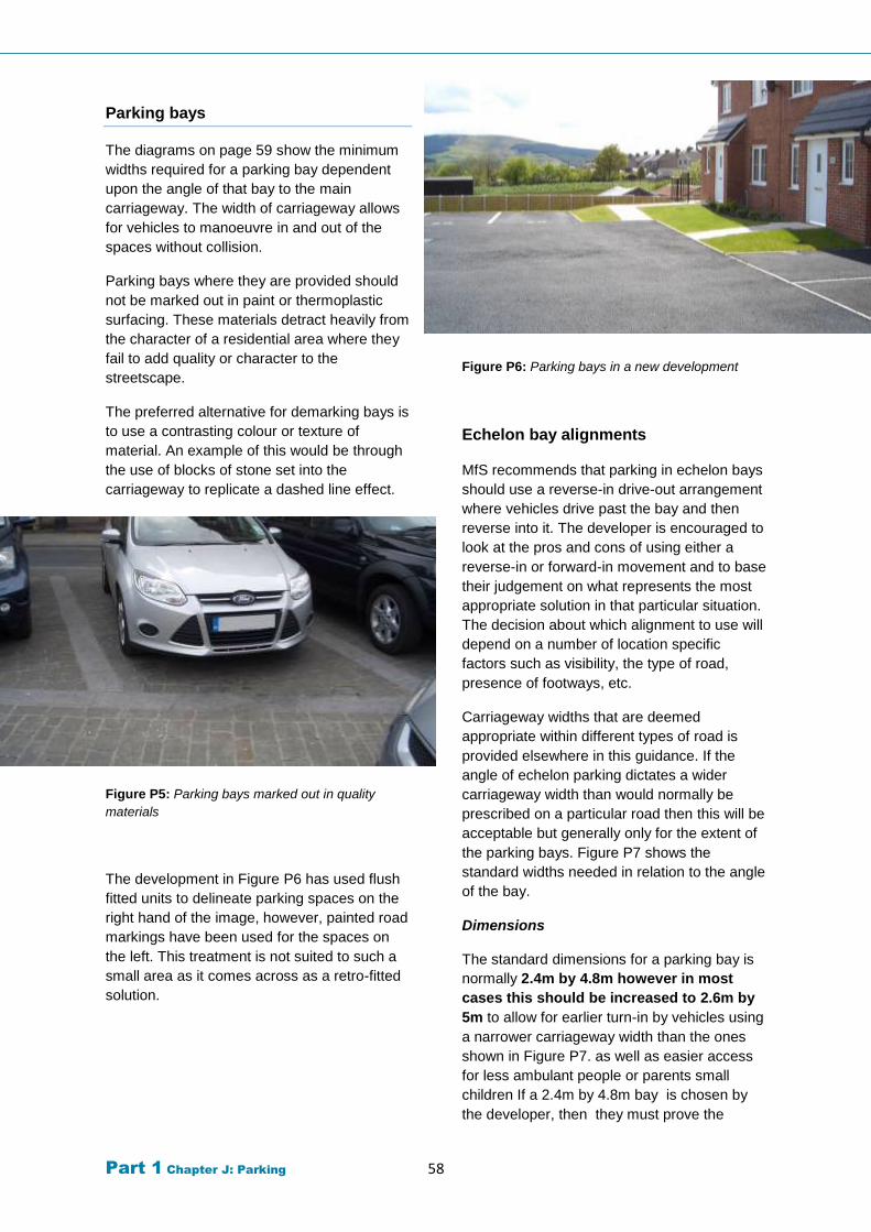
Part 1 Chapter J: Parking 58
Parking bays
The diagrams on page 59 show the minimum
widths required for a parking bay dependent
upon the angle of that bay to the main
carriageway. The width of carriageway allows
for vehicles to manoeuvre in and out of the
spaces without collision.
Parking bays where they are provided should
not be marked out in paint or thermoplastic
surfacing. These materials detract heavily from
the character of a residential area where they
fail to add quality or character to the
streetscape.
The preferred alternative for demarking bays is
to use a contrasting colour or texture of
material. An example of this would be through
the use of blocks of stone set into the
carriageway to replicate a dashed line effect.
Figure P5: Parking bays marked out in quality
materials
The development in Figure P6 has used flush
fitted units to delineate parking spaces on the
right hand of the image, however, painted road
markings have been used for the spaces on
the left. This treatment is not suited to such a
small area as it comes across as a retro-fitted
solution.
Figure P6: Parking bays in a new development
Echelon bay alignments
MfS recommends that parking in echelon bays
should use a reverse-in drive-out arrangement
where vehicles drive past the bay and then
reverse into it. The developer is encouraged to
look at the pros and cons of using either a
reverse-in or forward-in movement and to base
their judgement on what represents the most
appropriate solution in that particular situation.
The decision about which alignment to use will
depend on a number of location specific
factors such as visibility, the type of road,
presence of footways, etc.
Carriageway widths that are deemed
appropriate within different types of road is
provided elsewhere in this guidance. If the
angle of echelon parking dictates a wider
carriageway width than would normally be
prescribed on a particular road then this will be
acceptable but generally only for the extent of
the parking bays. Figure P7 shows the
standard widths needed in relation to the angle
of the bay.
Dimensions
The standard dimensions for a parking bay is
normally 2.4m by 4.8m however in most
cases this should be increased to 2.6m by
5m to allow for earlier turn-in by vehicles using
a narrower carriageway width than the ones
shown in Figure P7. as well as easier access
for less ambulant people or parents small
children If a 2.4m by 4.8m bay is chosen by
the developer, then they must prove the
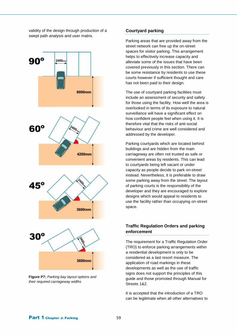
Part 1 Chapter J: Parking 59
validity of the design through production of a
swept path analysis and user matrix.
Figure P7: Parking bay layout options and
their required carriageway widths
Courtyard parking
Parking areas that are provided away from the
street network can free up the on-street
spaces for visitor parking. This arrangement
helps to effectively increase capacity and
alleviate some of the issues that have been
covered previously in this section. There can
be some resistance by residents to use these
courts however if sufficient thought and care
has not been paid to their design.
The use of courtyard parking facilities must
include an assessment of security and safety
for those using the facility. How well the area is
overlooked in terms of its exposure to natural
surveillance will have a significant effect on
how confident people feel when using it. It is
therefore vital that the risks of anti-social
behaviour and crime are well considered and
addressed by the developer.
Parking courtyards which are located behind
buildings and are hidden from the main
carriageway are often not trusted as safe or
convenient areas by residents. This can lead
to courtyards being left vacant or under
capacity as people decide to park on-street
instead. Nevertheless, it is preferable to draw
some parking away from the street. The layout
of parking courts is the responsibility of the
developer and they are encouraged to explore
designs which would appeal to residents to
use the facility rather than occupying on-street
space.
Traffic Regulation Orders and parking
enforcement
The requirement for a Traffic Regulation Order
(TRO) to enforce parking arrangements within
a residential development is only to be
considered as a last resort measure. The
application of road markings in these
developments as well as the use of traffic
signs does not support the principles of this
guide and those promoted through Manual for
Streets 1&2.
It is accepted that the introduction of a TRO
can be legitimate when all other alternatives to
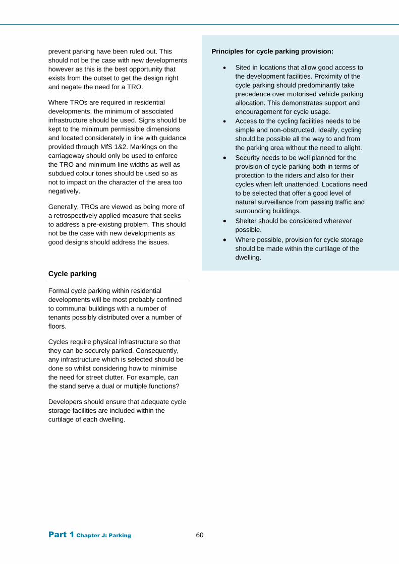
Part 1 Chapter J: Parking 60
prevent parking have been ruled out. This
should not be the case with new developments
however as this is the best opportunity that
exists from the outset to get the design right
and negate the need for a TRO.
Where TROs are required in residential
developments, the minimum of associated
infrastructure should be used. Signs should be
kept to the minimum permissible dimensions
and located considerately in line with guidance
provided through MfS 1&2. Markings on the
carriageway should only be used to enforce
the TRO and minimum line widths as well as
subdued colour tones should be used so as
not to impact on the character of the area too
negatively.
Generally, TROs are viewed as being more of
a retrospectively applied measure that seeks
to address a pre-existing problem. This should
not be the case with new developments as
good designs should address the issues.
Cycle parking
Formal cycle parking within residential
developments will be most probably confined
to communal buildings with a number of
tenants possibly distributed over a number of
floors.
Cycles require physical infrastructure so that
they can be securely parked. Consequently,
any infrastructure which is selected should be
done so whilst considering how to minimise
the need for street clutter. For example, can
the stand serve a dual or multiple functions?
Developers should ensure that adequate cycle
storage facilities are included within the
curtilage of each dwelling.
Principles for cycle parking provision:
Sited in locations that allow good access to
the development facilities. Proximity of the
cycle parking should predominantly take
precedence over motorised vehicle parking
allocation. This demonstrates support and
encouragement for cycle usage.
Access to the cycling facilities needs to be
simple and non-obstructed. Ideally, cycling
should be possible all the way to and from
the parking area without the need to alight.
Security needs to be well planned for the
provision of cycle parking both in terms of
protection to the riders and also for their
cycles when left unattended. Locations need
to be selected that offer a good level of
natural surveillance from passing traffic and
surrounding buildings.
Shelter should be considered wherever
possible.
Where possible, provision for cycle storage
should be made within the curtilage of the
dwelling.
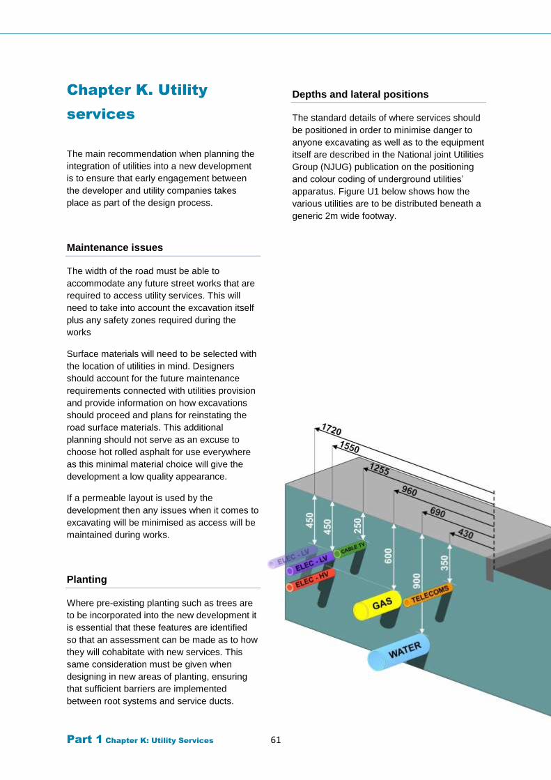
Part 1 Chapter K: Utility Services 61
Chapter K. Utility
services
The main recommendation when planning the
integration of utilities into a new development
is to ensure that early engagement between
the developer and utility companies takes
place as part of the design process.
Maintenance issues
The width of the road must be able to
accommodate any future street works that are
required to access utility services. This will
need to take into account the excavation itself
plus any safety zones required during the
works
Surface materials will need to be selected with
the location of utilities in mind. Designers
should account for the future maintenance
requirements connected with utilities provision
and provide information on how excavations
should proceed and plans for reinstating the
road surface materials. This additional
planning should not serve as an excuse to
choose hot rolled asphalt for use everywhere
as this minimal material choice will give the
development a low quality appearance.
If a permeable layout is used by the
development then any issues when it comes to
excavating will be minimised as access will be
maintained during works.
Planting
Where pre-existing planting such as trees are
to be incorporated into the new development it
is essential that these features are identified
so that an assessment can be made as to how
they will cohabitate with new services. This
same consideration must be given when
designing in new areas of planting, ensuring
that sufficient barriers are implemented
between root systems and service ducts.
Depths and lateral positions
The standard details of where services should
be positioned in order to minimise danger to
anyone excavating as well as to the equipment
itself are described in the National joint Utilities
Group (NJUG) publication on the positioning
and colour coding of underground utilities’
apparatus. Figure U1 below shows how the
various utilities are to be distributed beneath a
generic 2m wide footway.
National Joint Utilities Group (NJUG)
Publications Volume 1, NJUG Guidelines on the Positioning and Colour Coding of Underground Utilities’ Apparatus
Visit:
www.NJUG.co.uk or
NJUG, 28 Broadway, Westminster, London, SW1 9JX
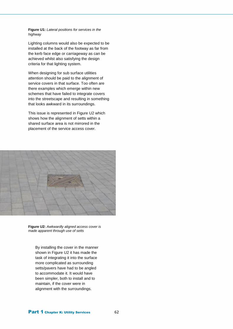
Part 1 Chapter K: Utility Services 62
Figure U1: Lateral positions for services in the
highway
Lighting columns would also be expected to be
installed at the back of the footway as far from
the kerb face edge or carriageway as can be
achieved whilst also satisfying the design
criteria for that lighting system.
When designing for sub surface utilities
attention should be paid to the alignment of
service covers in that surface. Too often are
there examples which emerge within new
schemes that have failed to integrate covers
into the streetscape and resulting in something
that looks awkward in its surroundings.
This issue is represented in Figure U2 which
shows how the alignment of setts within a
shared surface area is not mirrored in the
placement of the service access cover.
Figure U2: Awkwardly aligned access cover is made apparent through use of setts
By installing the cover in the manner
shown in Figure U2 it has made the
task of integrating it into the surface
more complicated as surrounding
setts/pavers have had to be angled
to accommodate it. It would have
been simpler, both to install and to
maintain, if the cover were in
alignment with the surroundings.
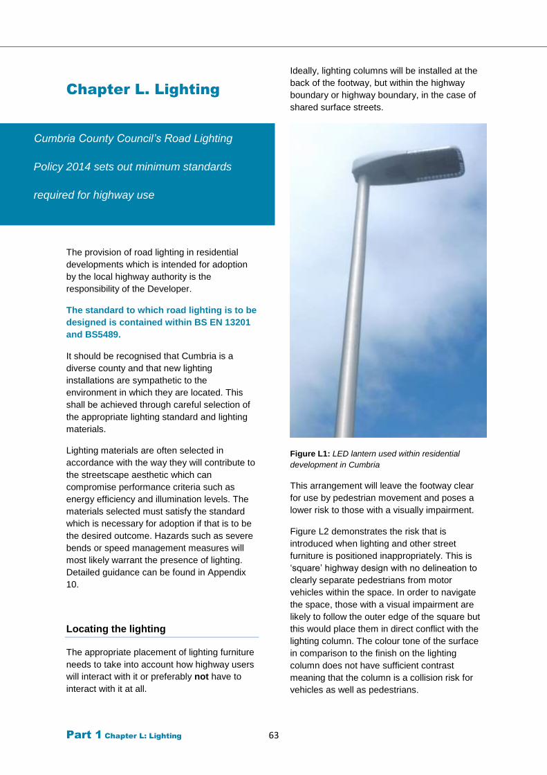
Part 1 Chapter L: Lighting 63
Chapter L. Lighting
Cumbria County Council’s Road Lighting
Policy 2014 sets out minimum standards
required for highway use
The provision of road lighting in residential
developments which is intended for adoption
by the local highway authority is the
responsibility of the Developer.
The standard to which road lighting is to be
designed is contained within BS EN 13201
and BS5489.
It should be recognised that Cumbria is a
diverse county and that new lighting
installations are sympathetic to the
environment in which they are located. This
shall be achieved through careful selection of
the appropriate lighting standard and lighting
materials.
Lighting materials are often selected in
accordance with the way they will contribute to
the streetscape aesthetic which can
compromise performance criteria such as
energy efficiency and illumination levels. The
materials selected must satisfy the standard
which is necessary for adoption if that is to be
the desired outcome. Hazards such as severe
bends or speed management measures will
most likely warrant the presence of lighting.
Detailed guidance can be found in Appendix
10.
Locating the lighting
The appropriate placement of lighting furniture
needs to take into account how highway users
will interact with it or preferably not have to
interact with it at all.
Ideally, lighting columns will be installed at the
back of the footway, but within the highway
boundary or highway boundary, in the case of
shared surface streets.
Figure L1: LED lantern used within residential
development in Cumbria
This arrangement will leave the footway clear
for use by pedestrian movement and poses a
lower risk to those with a visually impairment.
Figure L2 demonstrates the risk that is
introduced when lighting and other street
furniture is positioned inappropriately. This is
‘square’ highway design with no delineation to
clearly separate pedestrians from motor
vehicles within the space. In order to navigate
the space, those with a visual impairment are
likely to follow the outer edge of the square but
this would place them in direct conflict with the
lighting column. The colour tone of the surface
in comparison to the finish on the lighting
column does not have sufficient contrast
meaning that the column is a collision risk for
vehicles as well as pedestrians.
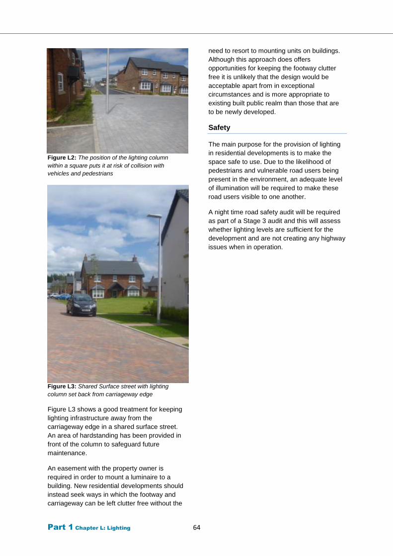
Part 1 Chapter L: Lighting 64
Figure L2: The position of the lighting column
within a square puts it at risk of collision with
vehicles and pedestrians
Figure L3: Shared Surface street with lighting
column set back from carriageway edge
Figure L3 shows a good treatment for keeping
lighting infrastructure away from the
carriageway edge in a shared surface street.
An area of hardstanding has been provided in
front of the column to safeguard future
maintenance.
An easement with the property owner is
required in order to mount a luminaire to a
building. New residential developments should
instead seek ways in which the footway and
carriageway can be left clutter free without the
need to resort to mounting units on buildings.
Although this approach does offers
opportunities for keeping the footway clutter
free it is unlikely that the design would be
acceptable apart from in exceptional
circumstances and is more appropriate to
existing built public realm than those that are
to be newly developed.
Safety
The main purpose for the provision of lighting
in residential developments is to make the
space safe to use. Due to the likelihood of
pedestrians and vulnerable road users being
present in the environment, an adequate level
of illumination will be required to make these
road users visible to one another.
A night time road safety audit will be required
as part of a Stage 3 audit and this will assess
whether lighting levels are sufficient for the
development and are not creating any highway
issues when in operation.
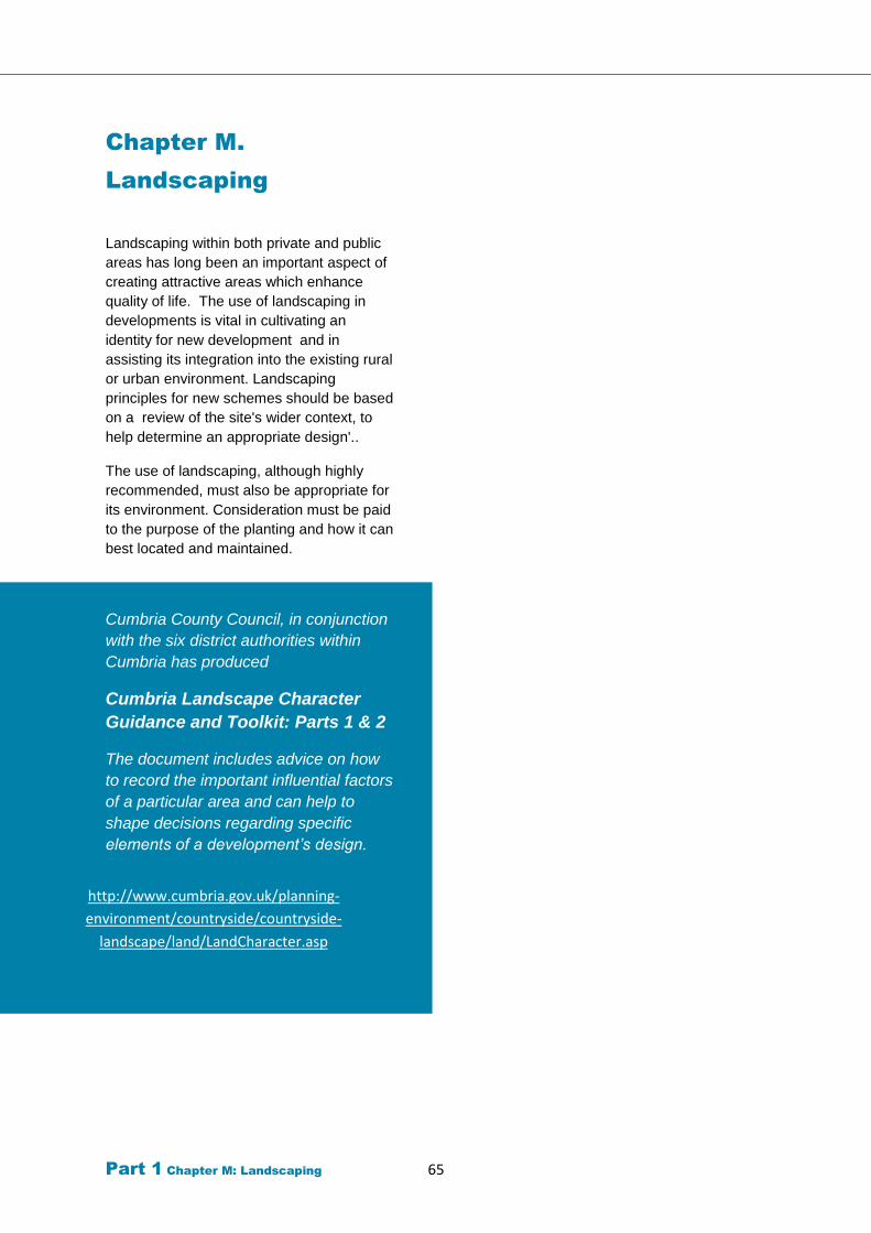
Part 1 Chapter M: Landscaping 65
http://www.cumbria.gov.uk/planning-
environment/countryside/countryside-
landscape/land/LandCharacter.asp
Chapter M.
Landscaping
Landscaping within both private and public
areas has long been an important aspect of
creating attractive areas which enhance
quality of life. The use of landscaping in
developments is vital in cultivating an
identity for new development and in
assisting its integration into the existing rural
or urban environment. Landscaping
principles for new schemes should be based
on a review of the site's wider context, to
help determine an appropriate design'..
The use of landscaping, although highly
recommended, must also be appropriate for
its environment. Consideration must be paid
to the purpose of the planting and how it can
best located and maintained.
Cumbria County Council, in conjunction
with the six district authorities within
Cumbria has produced
Cumbria Landscape Character
Guidance and Toolkit: Parts 1 & 2
The document includes advice on how
to record the important influential factors
of a particular area and can help to
shape decisions regarding specific
elements of a development’s design.
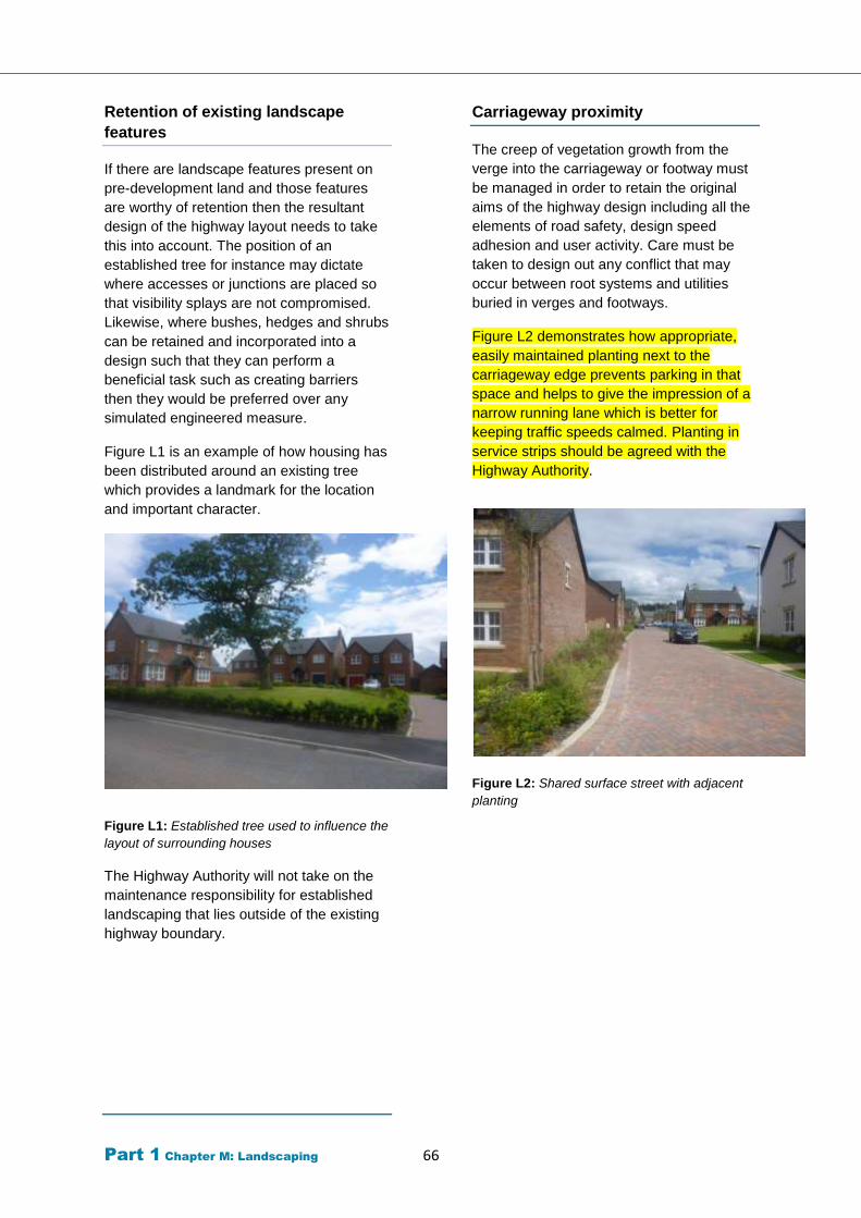
Part 1 Chapter M: Landscaping 66
Retention of existing landscape
features
If there are landscape features present on
pre-development land and those features
are worthy of retention then the resultant
design of the highway layout needs to take
this into account. The position of an
established tree for instance may dictate
where accesses or junctions are placed so
that visibility splays are not compromised.
Likewise, where bushes, hedges and shrubs
can be retained and incorporated into a
design such that they can perform a
beneficial task such as creating barriers
then they would be preferred over any
simulated engineered measure.
Figure L1 is an example of how housing has
been distributed around an existing tree
which provides a landmark for the location
and important character.
Figure L1: Established tree used to influence the
layout of surrounding houses
The Highway Authority will not take on the
maintenance responsibility for established
landscaping that lies outside of the existing
highway boundary.
Carriageway proximity
The creep of vegetation growth from the
verge into the carriageway or footway must
be managed in order to retain the original
aims of the highway design including all the
elements of road safety, design speed
adhesion and user activity. Care must be
taken to design out any conflict that may
occur between root systems and utilities
buried in verges and footways.
Figure L2 demonstrates how appropriate,
easily maintained planting next to the
carriageway edge prevents parking in that
space and helps to give the impression of a
narrow running lane which is better for
keeping traffic speeds calmed. Planting in
service strips should be agreed with the
Highway Authority.
Figure L2: Shared surface street with adjacent
planting

Part 1 Chapter M: Landscaping 67
Considerations that need to be taken into
account before planting is introduced into
the streetscape will include:
Any trees which are to be located
within the adoptable highway area
need to have a canopy height which
allows good visibility for drivers and
other road users on approach.
Large canopies on trees will cast
shadows which may create areas of
poor visibility disguising road users
from one another. Damp may prevail in
shaded areas also adding to the risk of
spots of ice occurring or areas of
reduced surface friction due to mossy
growth.
The selected species should be chosen
with consideration given to how long its
foliage will be on display seasonally,
the colours that will be displayed and
the amount of foliage that will be
discharged come autumn.
Any trees which produce particular
types of fruit or flowers, may
consequently attract wildlife that can
lead to the carriageway below
becoming covered in animal waste. An
accumulation of this waste is not only
unsightly but also potentially unhealthy
for anyone coming into contact with it.
Trees can be planted within a range of
infiltration SuDs components to
improve performance or as a
standalone filter for pollutants from
runoff directly. Trees in planting beds,
pits, structural soils below pavement
can be used as part of the surface
water management system.
Street lighting must be unaffected by
the location of trees with care taken to
ensure shadows are not created in the
hours of darkness.
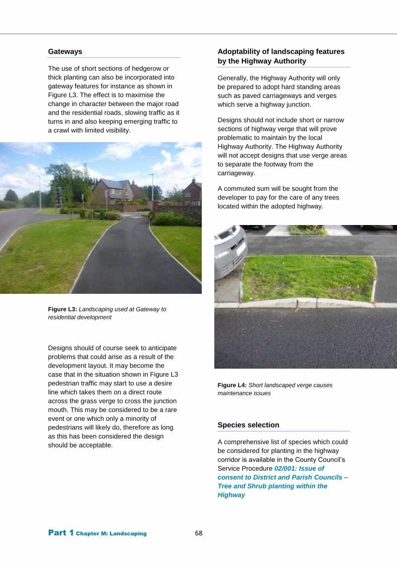
Part 1 Chapter M: Landscaping 68
Gateways
The use of short sections of hedgerow or
thick planting can also be incorporated into
gateway features for instance as shown in
Figure L3. The effect is to maximise the
change in character between the major road
and the residential roads, slowing traffic as it
turns in and also keeping emerging traffic to
a crawl with limited visibility.
Figure L3: Landscaping used at Gateway to
residential development
Designs should of course seek to anticipate
problems that could arise as a result of the
development layout. It may become the
case that in the situation shown in Figure L3
pedestrian traffic may start to use a desire
line which takes them on a direct route
across the grass verge to cross the junction
mouth. This may be considered to be a rare
event or one which only a minority of
pedestrians will likely do, therefore as long
as this has been considered the design
should be acceptable.
Adoptability of landscaping features
by the Highway Authority
Generally, the Highway Authority will only
be prepared to adopt hard standing areas
such as paved carriageways and verges
which serve a highway junction.
Designs should not include short or narrow
sections of highway verge that will prove
problematic to maintain by the local
Highway Authority. The Highway Authority
will not accept designs that use verge areas
to separate the footway from the
carriageway.
A commuted sum will be sought from the
developer to pay for the care of any trees
located within the adopted highway.
Figure L4: Short landscaped verge causes
maintenance issues
Species selection
A comprehensive list of species which could
be considered for planting in the highway
corridor is available in the County Council’s
Service Procedure 02/001: Issue of
consent to District and Parish Councils –
Tree and Shrub planting within the
Highway
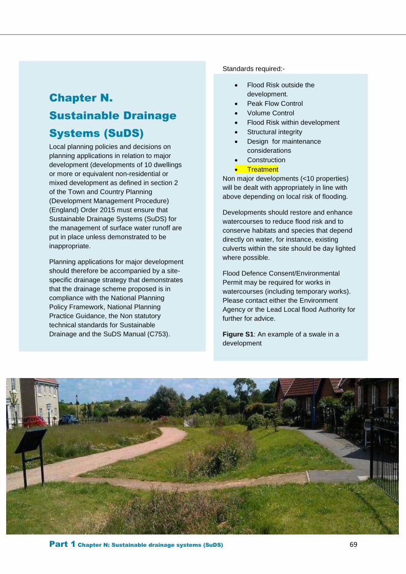
Part 1 Chapter N: Sustainable drainage systems (SuDS) 69
Chapter N.
Sustainable Drainage
Systems (SuDS)
Local planning policies and decisions on
planning applications in relation to major
development (developments of 10 dwellings
or more or equivalent non-residential or
mixed development as defined in section 2
of the Town and Country Planning
(Development Management Procedure)
(England) Order 2015 must ensure that
Sustainable Drainage Systems (SuDS) for
the management of surface water runoff are
put in place unless demonstrated to be
inappropriate.
Planning applications for major development
should therefore be accompanied by a site-
specific drainage strategy that demonstrates
that the drainage scheme proposed is in
compliance with the National Planning
Policy Framework, National Planning
Practice Guidance, the Non statutory
technical standards for Sustainable
Drainage and the SuDS Manual (C753).
Standards required:-
Flood Risk outside the
development.
Peak Flow Control
Volume Control
Flood Risk within development
Structural integrity
Design for maintenance
considerations
Construction
Treatment
Non major developments (<10 properties)
will be dealt with appropriately in line with
above depending on local risk of flooding.
Developments should restore and enhance
watercourses to reduce flood risk and to
conserve habitats and species that depend
directly on water, for instance, existing
culverts within the site should be day lighted
where possible.
Flood Defence Consent/Environmental
Permit may be required for works in
watercourses (including temporary works).
Please contact either the Environment
Agency or the Lead Local flood Authority for
further for advice.
Figure S1: An example of a swale in a
development
Part 1 Chapter N: Sustainable drainage systems (SuDS) 70
Drainage Strategy
Drainage should be considered early in the
development planning and design process,
along with other key considerations. Existing
watercourses, existing flows of surface
water across the site, and existing drainage
systems, must be taken into consideration
and the drainage strategy should mimic
natural drainage patterns as closely as
possible.
Water generated from off site that passes
through the site must be managed so that it
can continue to pass through the site
without increasing flood risk.
Within the site, the most vulnerable
elements of the proposed development
should be located in the areas of lowest
flood risk. This would usually mean that
areas known to be at risk of surface water
flooding should be left as green space within
the development.
Priority must be given to the use of
sustainable drainage systems (SuDS).
Sustainable Drainage Systems
(SuDS)
Sustainable Drainage Systems (SuDS)
mimic natural drainage patterns and provide
water quantity (flooding), water quality
(pollution), amenity and biodiversity
benefits. The SuDS manual C753
(published by CIRIA) provides guidance on
the planning, design, construction and
maintenance of SuDS; available at
www.susdrain.org/resources/ciria-
guidance.html.
Other useful information:
• Susdrain the community for sustainable
drainage www.susdrain.org.
• UK SuDS Tools Web site - HR
Wallingford www.uksuds.com.
• BS8582:2013 Code of Practice for
Surface Water Management for
Development Sites.
• DEFRA Non-Statutory Technical
Standards for Sustainable Drainage
Systems
https://www.gov.uk/government/uploads/
system/uploads/attachment_data/file/415
773/sustainable-drainage-technical-
standards.pdf
LASOO Non-Statutory Technical
Standards for Sustainable Drainage
Systems guidance notes
http://www.cumbria.gov.uk/elibrary/Conte
nt/Internet/544/3887/5894/4250810222.p
df
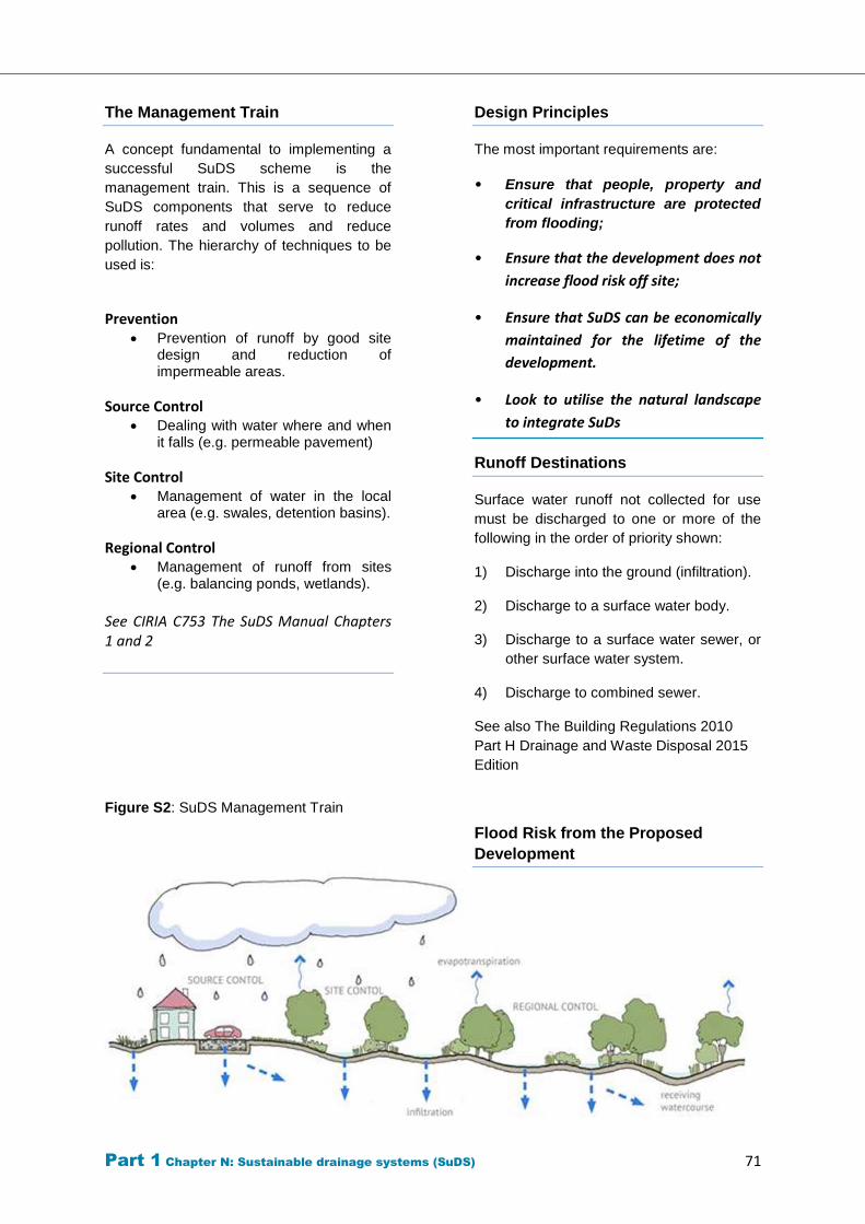
Part 1 Chapter N: Sustainable drainage systems (SuDS) 71
The Management Train
A concept fundamental to implementing a
successful SuDS scheme is the
management train. This is a sequence of
SuDS components that serve to reduce
runoff rates and volumes and reduce
pollution. The hierarchy of techniques to be
used is:
Prevention Prevention of runoff by good site
design and reduction of impermeable areas.
Source Control Dealing with water where and when
it falls (e.g. permeable pavement)
Site Control Management of water in the local
area (e.g. swales, detention basins).
Regional Control Management of runoff from sites
(e.g. balancing ponds, wetlands).
See CIRIA C753 The SuDS Manual Chapters 1 and 2
Figure S2: SuDS Management Train
Design Principles
The most important requirements are:
• Ensure that people, property and
critical infrastructure are protected
from flooding;
• Ensure that the development does not
increase flood risk off site;
• Ensure that SuDS can be economically
maintained for the lifetime of the
development.
• Look to utilise the natural landscape
to integrate SuDs
Runoff Destinations
Surface water runoff not collected for use
must be discharged to one or more of the
following in the order of priority shown:
1) Discharge into the ground (infiltration).
2) Discharge to a surface water body.
3) Discharge to a surface water sewer, or
other surface water system.
4) Discharge to combined sewer.
See also The Building Regulations 2010
Part H Drainage and Waste Disposal 2015
Edition
Flood Risk from the Proposed
Development
Part 1 Chapter N: Sustainable drainage systems (SuDS) 72
The drainage system must be designed so
that, unless an area is designed to hold
and/or convey water, flooding does not
occur during a 1 in 100 year rainfall event
plus an appropriate climate change
allowance in any part of a building (including
a basement) or in any utility plant
susceptible to water (e.g. pumping station or
electricity substation) within the
development. Calculations must include an
allowance for urban creep where required.
The design of the site must ensure that
flows resulting from rainfall event in excess
of the 1 in 100 year plus climate allowance
are managed in exceedance routes that
avoid risk to people and property both on
and off site.
Peak Flow Control
The peak runoff rate from the developed site
for the 1 in 1, 1 in 30 and 1 in 100 year
rainfall events to include for urban creep
where required and climate change must
not exceed the peak greenfield runoff rate
from the site for the same event.
Greenfield runoff rate is to be determined
using the Institute of Hydrology (IH) Report
124 or Flood Estimation Handbook (FEH)
methods.
See CIRIA C753 The SuDS Manual Chapter 3
Volume Control
The runoff volume from the developed site
for the 1 in 100 year 6 hour rainfall must not
exceed the Greenfield runoff volume for the
same event.
Should infiltration methods not be suitable
and it is not possible to achieve Greenfield
runoff volume then it must be demonstrated
that the increased volume will not increase
flood risk on or off site.
See CIRIA C753 The SuDS Manual Chapter
3
https://www.ciria.org//Resources/Free_publi
cations/SuDS_manual_C753.aspx
Pollution Control
SuDS design must ensure that the quality of
any receiving water body is not adversely
affected and preferably enhanced. Any
drainage system design should consider
use of various SuDS components likely to
be appropriate for different contributing and
receiving catchment characteristics.
See CIRIA C753 The SuDS Manual Chapter 4
& 26 for full guidance. https://www.ciria.org//Resources/Free_publica
tions/SuDS_manual_C753.aspx
See Ground Water Protection: See Ground
Water Protection Guides at
https://www.gov.uk/government/collections/gr
oundwater-protection
Designing for Exceedance
Site design must be such that when SuDS
features fail or are exceeded, exceedance
flows do not cause flooding of properties on
or off site. This is achieved by designing
suitable ground exceedance or flood
pathways. Runoff must be completely
contained within the drainage system
(including areas designed to hold or convey
water) for all events up to a 1 in 30 year
event.
The design of the site must ensure that
flows resulting from rainfall in excess of a 1
in 100 year rainfall event are managed in
exceedance routes that avoid risk to people
and property both on and off site. Consider
minor interventions to topography, such as
dropping or raising kerbs, creating
depressions.
See CIRIA C635 Designing for Exceedance
in Urban drainage - Good Practice
https://www.ciria.org/ItemDetail?iProductCo
de=C635&Category=BOOK&WebsiteKey=3f
18c87a-d62b-4eca-8ef4-9b09309c1c91
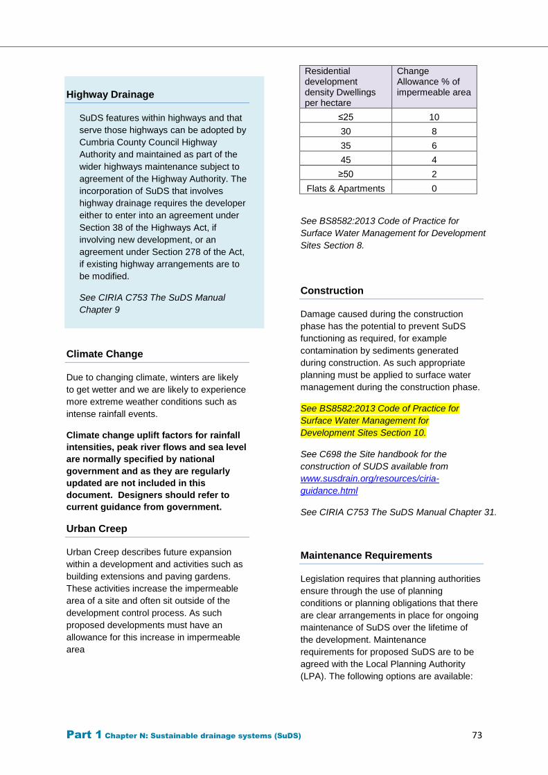
Part 1 Chapter N: Sustainable drainage systems (SuDS) 73
Highway Drainage
SuDS features within highways and that
serve those highways can be adopted by
Cumbria County Council Highway
Authority and maintained as part of the
wider highways maintenance subject to
agreement of the Highway Authority. The
incorporation of SuDS that involves
highway drainage requires the developer
either to enter into an agreement under
Section 38 of the Highways Act, if
involving new development, or an
agreement under Section 278 of the Act,
if existing highway arrangements are to
be modified.
See CIRIA C753 The SuDS Manual
Chapter 9
Climate Change
Due to changing climate, winters are likely
to get wetter and we are likely to experience
more extreme weather conditions such as
intense rainfall events.
Climate change uplift factors for rainfall
intensities, peak river flows and sea level
are normally specified by national
government and as they are regularly
updated are not included in this
document. Designers should refer to
current guidance from government.
Urban Creep
Urban Creep describes future expansion
within a development and activities such as
building extensions and paving gardens.
These activities increase the impermeable
area of a site and often sit outside of the
development control process. As such
proposed developments must have an
allowance for this increase in impermeable
area
Residential development density Dwellings per hectare
Change Allowance % of impermeable area
≤25 10
30 8
35 6
45 4
≥50 2
Flats & Apartments 0
See BS8582:2013 Code of Practice for
Surface Water Management for Development
Sites Section 8.
Construction
Damage caused during the construction
phase has the potential to prevent SuDS
functioning as required, for example
contamination by sediments generated
during construction. As such appropriate
planning must be applied to surface water
management during the construction phase.
See BS8582:2013 Code of Practice for
Surface Water Management for
Development Sites Section 10.
See C698 the Site handbook for the
construction of SUDS available from
www.susdrain.org/resources/ciria-
guidance.html
See CIRIA C753 The SuDS Manual Chapter 31.
Maintenance Requirements
Legislation requires that planning authorities
ensure through the use of planning
conditions or planning obligations that there
are clear arrangements in place for ongoing
maintenance of SuDS over the lifetime of
the development. Maintenance
requirements for proposed SuDS are to be
agreed with the Local Planning Authority
(LPA). The following options are available:
Part 1 Chapter N: Sustainable drainage systems (SuDS) 74
1) Adoption and maintenance of SuDS by
the local Water and Sewerage
Company via a section 104 Water
Industry Act agreement with that
company.
2) Adoption and maintenance of SuDS by
a management company. It must be
demonstrated to the satisfaction of the
LPA that the maintenance
arrangements and their funding will be
in place for the lifetime of the
development.
3) Adoption and maintenance of SuDS
relating to highway assessments where
agreed with the Local Highway
Authority
4) Maintenance of SuDS within property
curtilages by the homeowner. It must
be demonstrated to the satisfaction of
the LPA that maintenance will be
ensured for the lifetime of the
development.
It is not satisfactory to assume that
homeowners and subsequent homeowners
will be aware of the maintenance
requirement and responsibility; further
measures will be necessary. Those
measures must be proposed by the
applicant. Any methods involving
designation or registering a Land Charge
are to be agreed with the LPA. The options
for maintenance are:
1) Maintenance of SuDS within the
curtilages of land by the commercial
body or organisation that owns or
occupies that land. It must be
demonstrated to the satisfaction of the
LPA that the maintenance
arrangements and their funding will be
in place for the lifetime of the
development.
2) Should the SuDS not be adopted by a
Water and Sewerage Company the
following must be provided:
a. As built drawings and a
maintenance and operation
manual for all SuDS. This must
include physical access
arrangements for maintenance
and establishment of legal rights of
access in perpetuity prior to the
commencement of any phase of
the development. A copy of a
maintenance and operation
manual for single property SuDS
must be supplied to the relevant
residents.
b. Details of the organisation
responsible for the ongoing
maintenance of the SuDS for the
lifetime of the development.
c. Funding arrangements for SuDS
maintenance. It must be
demonstrated how the ongoing
maintenance of the SuDS for the
lifetime of the development will be
funded.
d. Health and safety risk assessment
for operation and maintenance of
the SuDS
See CIRIA C753 The SuDS Manual Chapter
32.
See BS8582:2013 Code of Practice for
Surface Water Management for
Development Sites Section 11.
See Susdrain – SuDS maintenance and
adoption options (England).
http://www.susdrain.org/files/resources/fact_
sheets/09_15_fact_sheet_suds_maintenanc
e_and_adoption_options_england_.pdf
SuDS Components
Sustainable drainage systems are designed
to control surface water run off close to
where it falls and mimic natural drainage as
closely as possible. They provide
opportunities to:
reduce the causes and impacts of
flooding;
remove pollutants from urban run-
off at source;
combine water management with
green space with benefits for
amenity, recreation and wildlife.
Part 1 Chapter N: Sustainable drainage systems (SuDS) 75
The full range of SuDS components,
including all of the following components,
should be investigated to determine which
are suitable for the site. Appendix 6
provides a list of SuDS components that the
County Council consider appropriate.
Rainwater harvesting
Green Roofs
Permeable Surfacing
Infiltration
Swales
Channels and Rills
Filter Drain
Filter Strips
Bio retention area
Rain gardens
Inlets and Outlets
Detention Basins
Infiltration Basins
Ponds
Wetlands
Appendix 7 provides details of the
minimum information that a developer
should consider providing when
submitting drainage strategy details.
Part 2
Part 2 Chapter A. Road hierarchy 76
Part 2
Chapters
A. Road hierarchy
B. Visibility
C. Carriageway width
D. Junctions and radii
E. Turning areas
F. Gradients
G. Vertical clearance
H. Signs & Markings
I. Sustainable travel
J. Parking
K. Utility services
L. Lighting
M. Landscaping
N. Access design
O. Mixed use site
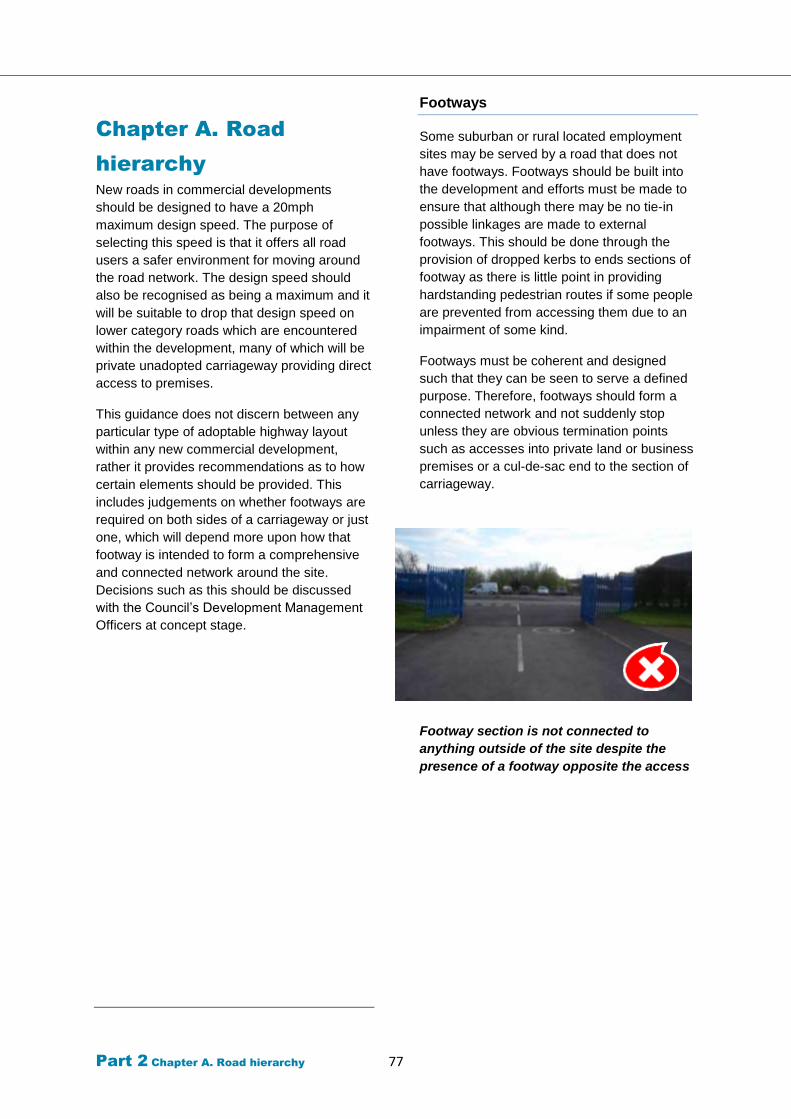
Part 2 Chapter A. Road hierarchy 77
Chapter A. Road
hierarchy
New roads in commercial developments
should be designed to have a 20mph
maximum design speed. The purpose of
selecting this speed is that it offers all road
users a safer environment for moving around
the road network. The design speed should
also be recognised as being a maximum and it
will be suitable to drop that design speed on
lower category roads which are encountered
within the development, many of which will be
private unadopted carriageway providing direct
access to premises.
This guidance does not discern between any
particular type of adoptable highway layout
within any new commercial development,
rather it provides recommendations as to how
certain elements should be provided. This
includes judgements on whether footways are
required on both sides of a carriageway or just
one, which will depend more upon how that
footway is intended to form a comprehensive
and connected network around the site.
Decisions such as this should be discussed
with the Council’s Development Management
Officers at concept stage.
Footways
Some suburban or rural located employment
sites may be served by a road that does not
have footways. Footways should be built into
the development and efforts must be made to
ensure that although there may be no tie-in
possible linkages are made to external
footways. This should be done through the
provision of dropped kerbs to ends sections of
footway as there is little point in providing
hardstanding pedestrian routes if some people
are prevented from accessing them due to an
impairment of some kind.
Footways must be coherent and designed
such that they can be seen to serve a defined
purpose. Therefore, footways should form a
connected network and not suddenly stop
unless they are obvious termination points
such as accesses into private land or business
premises or a cul-de-sac end to the section of
carriageway.
Footway section is not connected to
anything outside of the site despite the
presence of a footway opposite the access
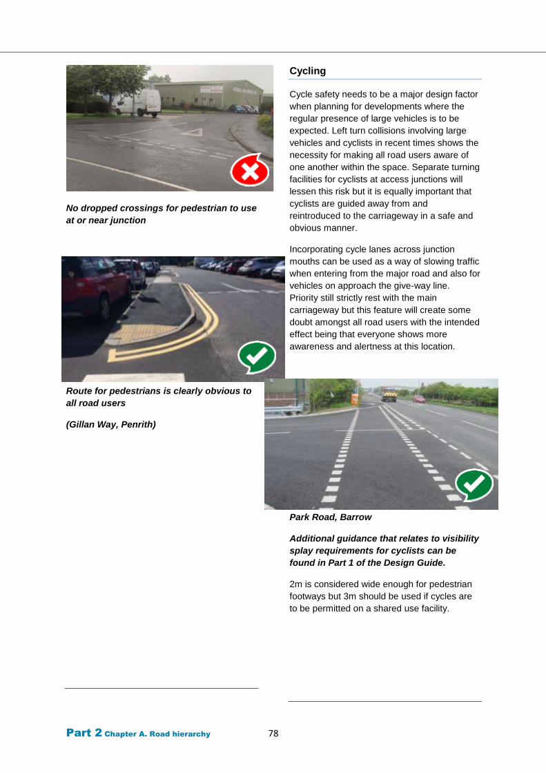
Part 2 Chapter A. Road hierarchy 78
No dropped crossings for pedestrian to use
at or near junction
Route for pedestrians is clearly obvious to
all road users
(Gillan Way, Penrith)
Cycling
Cycle safety needs to be a major design factor
when planning for developments where the
regular presence of large vehicles is to be
expected. Left turn collisions involving large
vehicles and cyclists in recent times shows the
necessity for making all road users aware of
one another within the space. Separate turning
facilities for cyclists at access junctions will
lessen this risk but it is equally important that
cyclists are guided away from and
reintroduced to the carriageway in a safe and
obvious manner.
Incorporating cycle lanes across junction
mouths can be used as a way of slowing traffic
when entering from the major road and also for
vehicles on approach the give-way line.
Priority still strictly rest with the main
carriageway but this feature will create some
doubt amongst all road users with the intended
effect being that everyone shows more
awareness and alertness at this location.
Park Road, Barrow
Additional guidance that relates to visibility
splay requirements for cyclists can be
found in Part 1 of the Design Guide.
2m is considered wide enough for pedestrian
footways but 3m should be used if cycles are
to be permitted on a shared use facility.

Part 2 Chapter A. Road hierarchy 79
Shared Surfaces
There will always be questions raised over the
practicality of vulnerable road users sharing
the same surface as large goods vehicles and
buses due their obvious disparity in size. The
main issue that is of concern is that of road
safety. HGVs are at a disadvantage to most
other road vehicles as they can suffer from
more limited field of vision, particularly when it
comes to seeing hazards that are in very close
proximity. With the presence of large heavy
goods vehicles it is often better to keep them
separated from vulnerable road users such as
pedestrians and cyclists.
This separation is recommended on roads
which serve multiple accesses to individual
business premises. However, once the HGV
enters a side road which will include courtyard
arrangements or indeed any other car parking
layout then the vulnerable road user will
become the highest priority in terms of
movement through that area.
Footways may still be distinguishable within
the highway surface but they should be
continuous such that they cut through the
space meaning vehicle must cross these
footways to enter and leave the area making
drivers show caution as they do so.
Measures which are currently in development,
both nationally and internationally to mitigate
against the risks posed by HGVs to vulnerable
road users through the adoption of new
technologies that will aid drivers in determining
what is around them. Industrial estates will see
a great deal of turning manoeuvres by large
vehicles within the environment and it is
imperative that conflict points are identified
and mitigated against within designs.
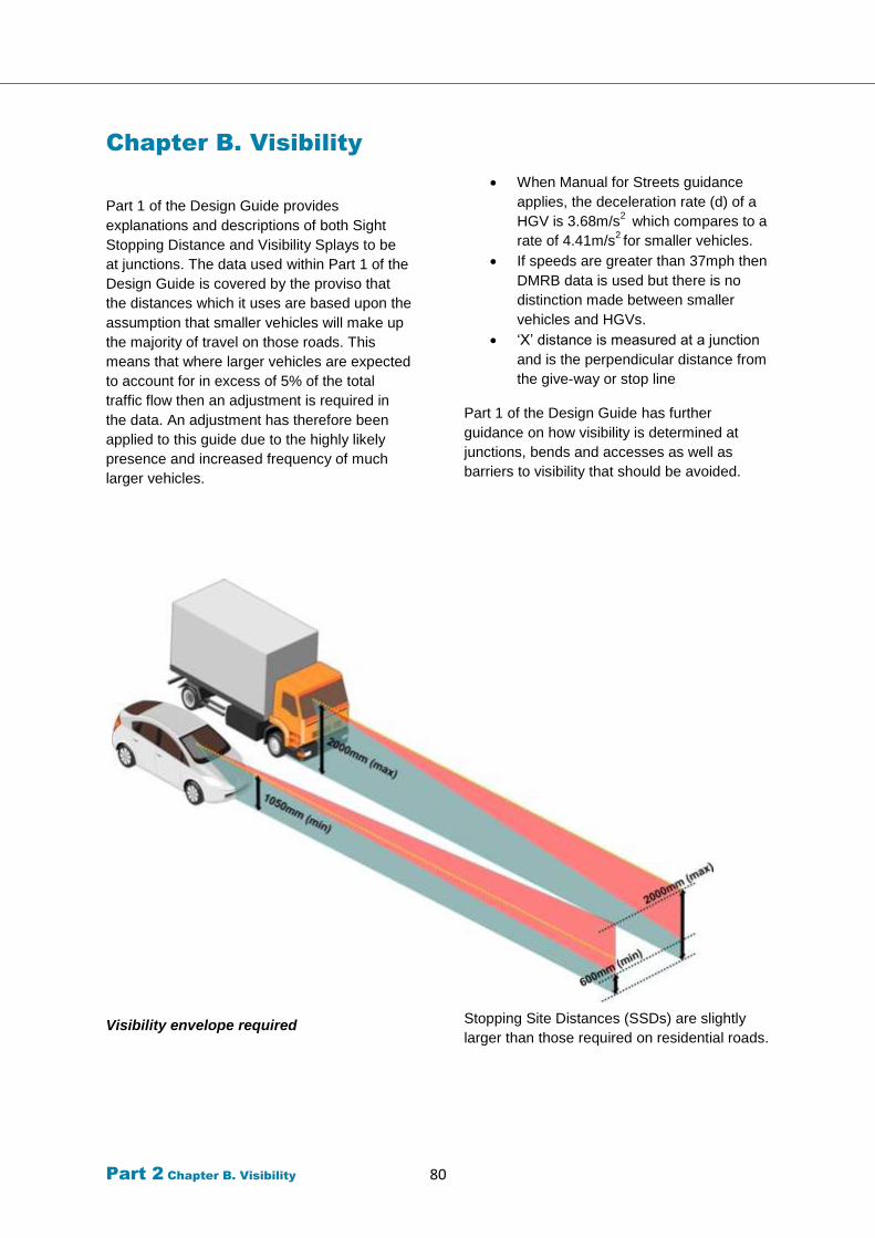
Part 2 Chapter B. Visibility 80
Chapter B. Visibility
Part 1 of the Design Guide provides
explanations and descriptions of both Sight
Stopping Distance and Visibility Splays to be
at junctions. The data used within Part 1 of the
Design Guide is covered by the proviso that
the distances which it uses are based upon the
assumption that smaller vehicles will make up
the majority of travel on those roads. This
means that where larger vehicles are expected
to account for in excess of 5% of the total
traffic flow then an adjustment is required in
the data. An adjustment has therefore been
applied to this guide due to the highly likely
presence and increased frequency of much
larger vehicles.
Visibility envelope required
When Manual for Streets guidance
applies, the deceleration rate (d) of a
HGV is 3.68m/s2 which compares to a
rate of 4.41m/s2 for smaller vehicles.
If speeds are greater than 37mph then
DMRB data is used but there is no
distinction made between smaller
vehicles and HGVs.
‘X’ distance is measured at a junction
and is the perpendicular distance from
the give-way or stop line
Part 1 of the Design Guide has further
guidance on how visibility is determined at
junctions, bends and accesses as well as
barriers to visibility that should be avoided.
Stopping Site Distances (SSDs) are slightly
larger than those required on residential roads.
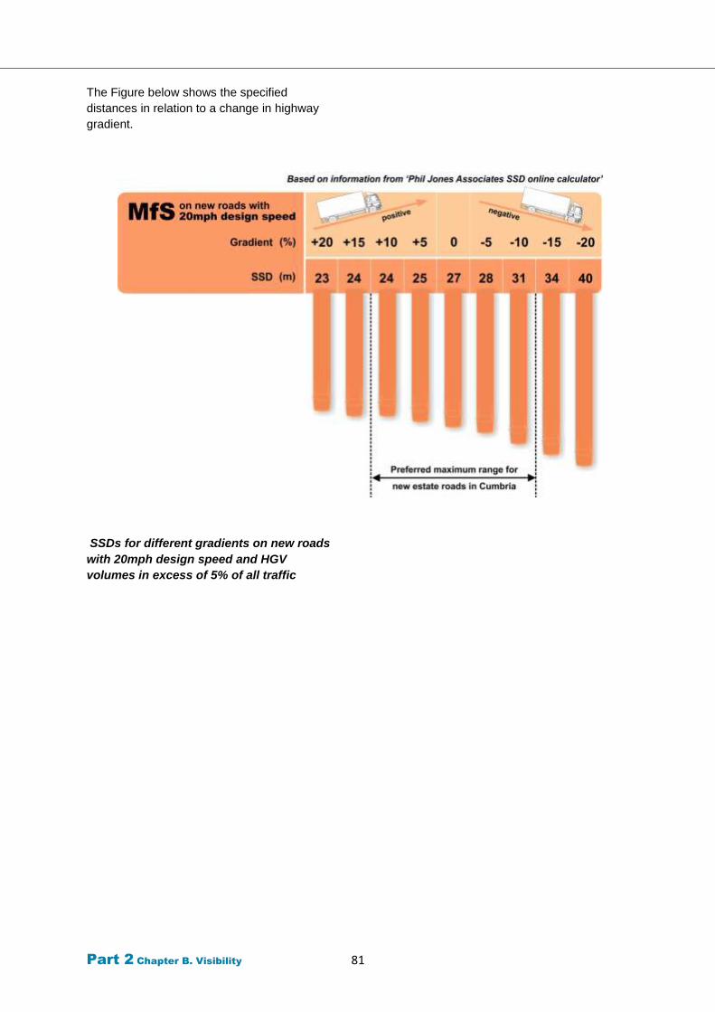
Part 2 Chapter B. Visibility 81
The Figure below shows the specified
distances in relation to a change in highway
gradient.
SSDs for different gradients on new roads
with 20mph design speed and HGV
volumes in excess of 5% of all traffic
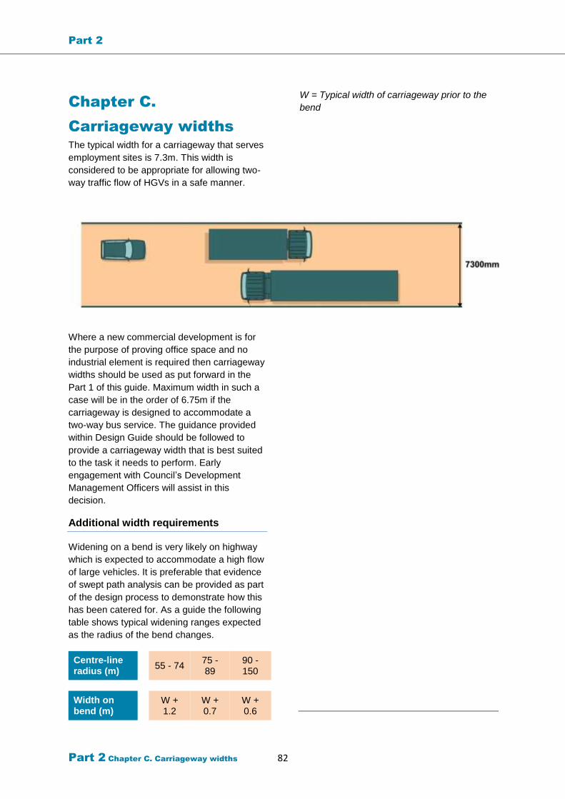
Part 2
Part 2 Chapter C. Carriageway widths 82
Chapter C.
Carriageway widths
The typical width for a carriageway that serves
employment sites is 7.3m. This width is
considered to be appropriate for allowing two-
way traffic flow of HGVs in a safe manner.
Where a new commercial development is for
the purpose of proving office space and no
industrial element is required then carriageway
widths should be used as put forward in the
Part 1 of this guide. Maximum width in such a
case will be in the order of 6.75m if the
carriageway is designed to accommodate a
two-way bus service. The guidance provided
within Design Guide should be followed to
provide a carriageway width that is best suited
to the task it needs to perform. Early
engagement with Council’s Development
Management Officers will assist in this
decision.
Additional width requirements
Widening on a bend is very likely on highway
which is expected to accommodate a high flow
of large vehicles. It is preferable that evidence
of swept path analysis can be provided as part
of the design process to demonstrate how this
has been catered for. As a guide the following
table shows typical widening ranges expected
as the radius of the bend changes.
Centre-line radius (m)
55 - 74 75 - 89
90 -150
Width on bend (m)
W + 1.2
W + 0.7
W + 0.6
W = Typical width of carriageway prior to the
bend

Part 2
Part 2 Chapter C. Carriageway widths 83
Over size loads
The different type of business activities that
are to be accommodated within the
employment site may require special
consideration. If a business is likely to
generate occasional traffic that is categorised
as ‘over size’ then this is a vital consideration
for the highway design. It will mean that central
median strips or traffic islands may not be
suitable.
The proximity of street lighting, signs,
landscaping and other vertical items must all
be assessed to ensure they do not present a
collision risk if these much wider or longer
loads are encountered.
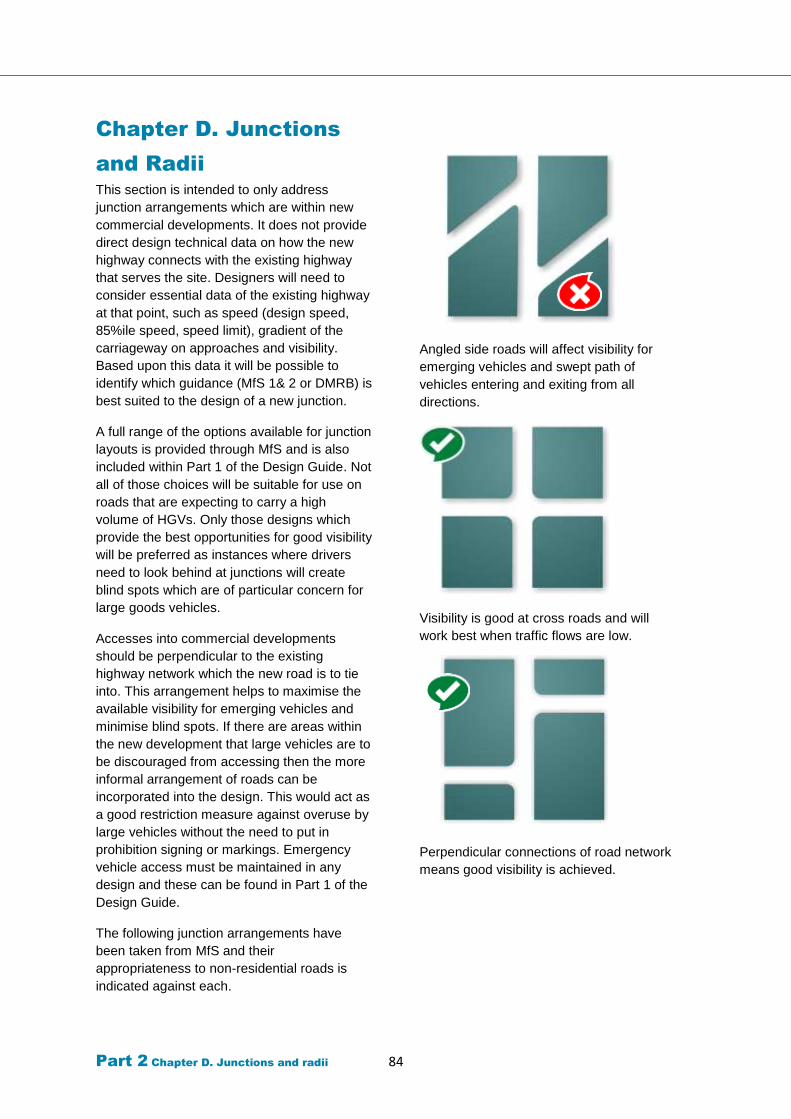
Part 2 Chapter D. Junctions and radii 84
Chapter D. Junctions
and Radii
This section is intended to only address
junction arrangements which are within new
commercial developments. It does not provide
direct design technical data on how the new
highway connects with the existing highway
that serves the site. Designers will need to
consider essential data of the existing highway
at that point, such as speed (design speed,
85%ile speed, speed limit), gradient of the
carriageway on approaches and visibility.
Based upon this data it will be possible to
identify which guidance (MfS 1& 2 or DMRB) is
best suited to the design of a new junction.
A full range of the options available for junction
layouts is provided through MfS and is also
included within Part 1 of the Design Guide. Not
all of those choices will be suitable for use on
roads that are expecting to carry a high
volume of HGVs. Only those designs which
provide the best opportunities for good visibility
will be preferred as instances where drivers
need to look behind at junctions will create
blind spots which are of particular concern for
large goods vehicles.
Accesses into commercial developments
should be perpendicular to the existing
highway network which the new road is to tie
into. This arrangement helps to maximise the
available visibility for emerging vehicles and
minimise blind spots. If there are areas within
the new development that large vehicles are to
be discouraged from accessing then the more
informal arrangement of roads can be
incorporated into the design. This would act as
a good restriction measure against overuse by
large vehicles without the need to put in
prohibition signing or markings. Emergency
vehicle access must be maintained in any
design and these can be found in Part 1 of the
Design Guide.
The following junction arrangements have
been taken from MfS and their
appropriateness to non-residential roads is
indicated against each.
Angled side roads will affect visibility for
emerging vehicles and swept path of
vehicles entering and exiting from all
directions.
Visibility is good at cross roads and will
work best when traffic flows are low.
Perpendicular connections of road network
means good visibility is achieved.
Part 2 Chapter D. Junctions and radii 85
Junction spacing
25m is the only distance which is stipulated by
the Design Guide when it comes to planning of
junction proximities. This distance is for
junctions that are located on the same side of
the carriageway and there is spacing between
junctions within a development is therefore not
considered to be in need of overly restrictive
recommendations when designing for
residential developments. It is preferable to
assume that this same relaxation can be
applied to commercial developments as
speeds should be designed to similarly low
and as long as sufficient visibility is available at
conflict points then this should prove to be a
workable approach. If a staggered junction
design means that long vehicles are likely to
overrun corners when exiting from one road
and snaking into the opposite road then
designs should be adapted to accommodate
this through carriageway construction or
design against the movement occurring in the
first place.
If sufficiently high enough traffic volumes are
anticipated it may become necessary, for the
reasons of congestion remediation to introduce
minimum spacing and these will be taken from
DMRB.
Junction control treatments
Roundabouts
Suitable where high volumes of HGV traffic are
anticipated as they can operate with greater
efficiency than a priority junction.
There are two types of roundabout which may
be used:
Mini-roundabout Circle diameter of the area
from kerbline to kerbline will be no greater than
28m
Normal – Inscribed Circle Diameter of no less
than 32m with a physically raised centre island
of no less than 4m in diameter
Probability of large goods vehicles using
roundabouts as U-turn facilities needs to be
assessed as mini-roundabouts may be
unsuited to that task and physical structures
placed in the centre of normal roundabouts
may be a collision risk.
Non-signalised junction
This arrangement is dependent upon existing
traffic flows across the junction and whether
sufficient opportunities exists for traffic to
emerge without undue or excessive waiting
periods. Typical layouts include T-junctions,
crossroads and staggered junctions that
usually rely upon give-way markings and/or
signs. These signs and markings can be
omitted where traffic speeds are sufficiently
low enough and the risk has been assessed
though a safety audit.
Signalised junction
This facility is dependent upon existing traffic
flows across the junction when judging
whether this option is suitable or not. Good
design should negate any requirement for
signals within a development unless the site is
split by a rail track or other segregating feature
that cannot be removed as part of the
development. Signals at the entrance to the
development where it meets with the existing
highway network may be necessary.
Part 2 Chapter D. Junctions and radii 86
Signals at the entrance to West Lakes
Science park where it meets the A595
Radii
Large goods vehicles will regularly require
access to these roads and it is a must that the
design geometry can cope with such
movements. Bends are especially susceptible
to the movements of these large vehicles if not
properly planned for. The cutting of a corner
on a bend can lead to infrastructure damage to
kerbs, service covers and other vertical
structures that may be placed close to the
carriageway edge. Over engineering a solution
to this issue will lead to other problems as the
provision of too generous a sweeping curve
means vehicles are able to enter and exit side
roads with excess speed and this can cause a
significant safety risk. It is crucial that a
balance can be struck between creating radii
that can cope with the swept path of a large
vehicle without leading to safety issues at
junctions.
The radius of a curve on a junction should
be a maximum of 10m.
6m could be provided if it is done so in
combination with an overrun area on the
corner.
The design purpose behind using smaller radii
means that traffic is forced to perform their turn
at a reduced speed than that which would
have been possible if the curve was more
generous. Pedestrians are also aided by the
provision of a smaller radius as they are able
keep to their desire line and cross junction with
minimal deflection. Part 1 of the Design Guide
includes additional information on this issue.
Structural integrity needs to be applied on
corners, particularly those that are designed to
appear more restrictive in terms of width than
they actually are. Giving the impression that a
bend is tight forces motorists into making their
manoeuvre at slower speeds and with more
awareness of what traffic may be coming from
the opposite direction.
This visual device can be achieved
through the use of overrun areas which
are implemented in a contrasting colour
or material. The use of white line hatching
should be avoided for the provision of this
purpose as they are more likely to need
replenishing more frequently and they are
visually detracting from the streetscape.
Overrun areas may be viewed by some
as parking places as they are surface
finished in a contrasting appearance to
the regular blacktop treatment. To prevent
this from occurring it may be necessary to
implement yellow line restrictions on the
bends. Long vehicles may have to enter
the opposing lane of travel when turning
in at a road Junction depending upon
how restrictive the corners of the junction
are. This will be acceptable where flows
are low such as cul-de-sacs that serve a
limited number of business premises.
Visibility splays at junctions should dictate
whether such an arrangement can be
used or not.
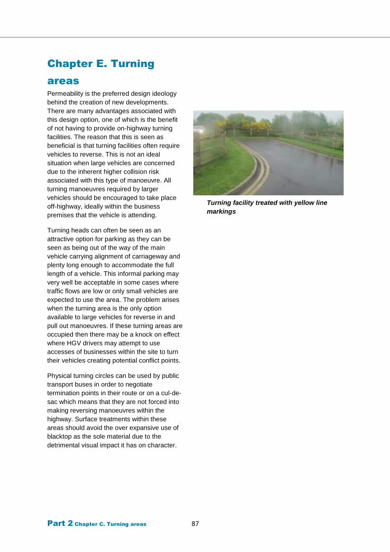
Part 2 Chapter C. Turning areas 87
Chapter E. Turning
areas
Permeability is the preferred design ideology
behind the creation of new developments.
There are many advantages associated with
this design option, one of which is the benefit
of not having to provide on-highway turning
facilities. The reason that this is seen as
beneficial is that turning facilities often require
vehicles to reverse. This is not an ideal
situation when large vehicles are concerned
due to the inherent higher collision risk
associated with this type of manoeuvre. All
turning manoeuvres required by larger
vehicles should be encouraged to take place
off-highway, ideally within the business
premises that the vehicle is attending.
Turning heads can often be seen as an
attractive option for parking as they can be
seen as being out of the way of the main
vehicle carrying alignment of carriageway and
plenty long enough to accommodate the full
length of a vehicle. This informal parking may
very well be acceptable in some cases where
traffic flows are low or only small vehicles are
expected to use the area. The problem arises
when the turning area is the only option
available to large vehicles for reverse in and
pull out manoeuvres. If these turning areas are
occupied then there may be a knock on effect
where HGV drivers may attempt to use
accesses of businesses within the site to turn
their vehicles creating potential conflict points.
Physical turning circles can be used by public
transport buses in order to negotiate
termination points in their route or on a cul-de-
sac which means that they are not forced into
making reversing manoeuvres within the
highway. Surface treatments within these
areas should avoid the over expansive use of
blacktop as the sole material due to the
detrimental visual impact it has on character.
Turning facility treated with yellow line
markings
Part 2 Chapter C. Turning areas 88
Speed management
The maximum design speed for any new
development road should be 20mph. The
geometry requirements of carriageways which
are designed for employment sites can
unfortunately often carry with it the risk that it
will be open to abuse through excessive
vehicle speeding and other anti-social vehicle
activity. These problems can be magnified for
employment sites, perhaps more so than for
residential estates because:
The significant drop in traffic flow and
other activity outside of normal working
hours means that the roads are very quiet
for long periods, particularly overnight.
The isolated nature of some of these sites
means that only minimal levels of
observation is carried out by police or
general public when compared with
residential areas.
As large vehicles must be accommodated
in these developments, the provision of
wider carriageways and other general
geometry provides a more forgiving layout
to those that choose to travel at excessive
speed.
There is less frontage activity expected in
employment developments than
residential developments and therefore
drivers have greater confidence that they
are the main priority on that road.
It is not possible or appropriate to apply the
same approaches to traffic calming in these
estates as for anywhere else on the highway
network. The following guidance looks at the
different types of speed reduction approaches
which could be applied to employment site
roads and the reasons behind them.
Where a commercial development serves
mainly offices and the proportion of HGVs and
other large vehicles is likely to be less then it
will be possible to use more traditional traffic
calming treatments as described in Part 1 of
the Design Guide.
Vertical measures
Vertical traffic calming is not suited to
environments with a large capacity of heavy
vehicles. The effect of such devices can have
a severe negative effect on vehicles, their
loads and their operators and the repeated
interaction between HGVs and these devices
means that it is more likely that regular
maintenance will be required due to the
severity of such impacts.
Vertical measures which are encouraged for
inclusion are raised tables which can be used
at junctions or for major crossing points. The
ramps which are used on these tables are
more forgiving than a traditional speed hump
or cushion device and therefore the transition
over them is more comfortable for the driver,
passenger and load.
Raised crossing points can be used across
access points which allow pedestrians an
uninterrupted route in line with any existing
footways either side of that access. These
raised crossings force drivers into adopting a
very low speed due to the increased likelihood
of pedestrians asserting their own priority at
that location and vehicles choosing to give way
to them. The physical height change will also
help to persuade drivers that slower is better to
preserve their comfort as they cross over the
feature.
Horizontal measures
Horizontal traffic calming must be designed to
adequately provide for the swept paths of long
vehicles without leading to the implementation
of a highway feature that does little to affect
the speed of smaller vehicles.
The conscious decision of where to place on-
street parking within an estate road is seen as
an efficient application of traffic calming
principles as it doesn’t waste opportunities of
merging functions such that parking is
provided for and speed is curbed in
combination. The provision of long unbroken
stretches of on-street parking on any one side
of the carriageway should be avoided. The
recommendation is that discrete lengths be
provided, creating a build-out type of
arrangement that will narrow the effective
carriageway width and encourage caution
between oncoming traffic flows.

Part 2 Chapter C. Turning areas 89
Psychological measures
Efforts should be made to minimise the
amount of road markings used within these
estate developments. Excessive use of
markings give the impression to motorists that
they are the main priority and lane markings
tend to give comfort to motorists who are more
aware of their allocation of road space and
consequently they are more inclined to travel
at speed.
With such limited options that could be
employed in these areas, particular
emphasis should be placed on the
alignment of the carriageway.
Ensuring that the use of long unbroken
straights is avoided will create some
speed reducing effect
Avoiding the provision of excessive
visibility splays at junctions and accesses
within the sites should make motorists
use greater caution when entering/exiting
and pedestrians will be equally
encouraged to demonstrate caution at
crossing points.
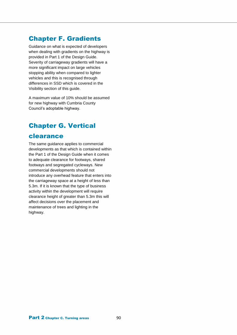
Part 2 Chapter C. Turning areas 90
Chapter F. Gradients
Guidance on what is expected of developers
when dealing with gradients on the highway is
provided in Part 1 of the Design Guide.
Severity of carriageway gradients will have a
more significant impact on large vehicles
stopping ability when compared to lighter
vehicles and this is recognised through
differences in SSD which is covered in the
Visibility section of this guide.
A maximum value of 10% should be assumed
for new highway with Cumbria County
Council’s adoptable highway.
Chapter G. Vertical
clearance
The same guidance applies to commercial
developments as that which is contained within
the Part 1 of the Design Guide when it comes
to adequate clearance for footways, shared
footways and segregated cycleways. New
commercial developments should not
introduce any overhead feature that enters into
the carriageway space at a height of less than
5.3m. If it is known that the type of business
activity within the development will require
clearance height of greater than 5.3m this will
affect decisions over the placement and
maintenance of trees and lighting in the
highway.
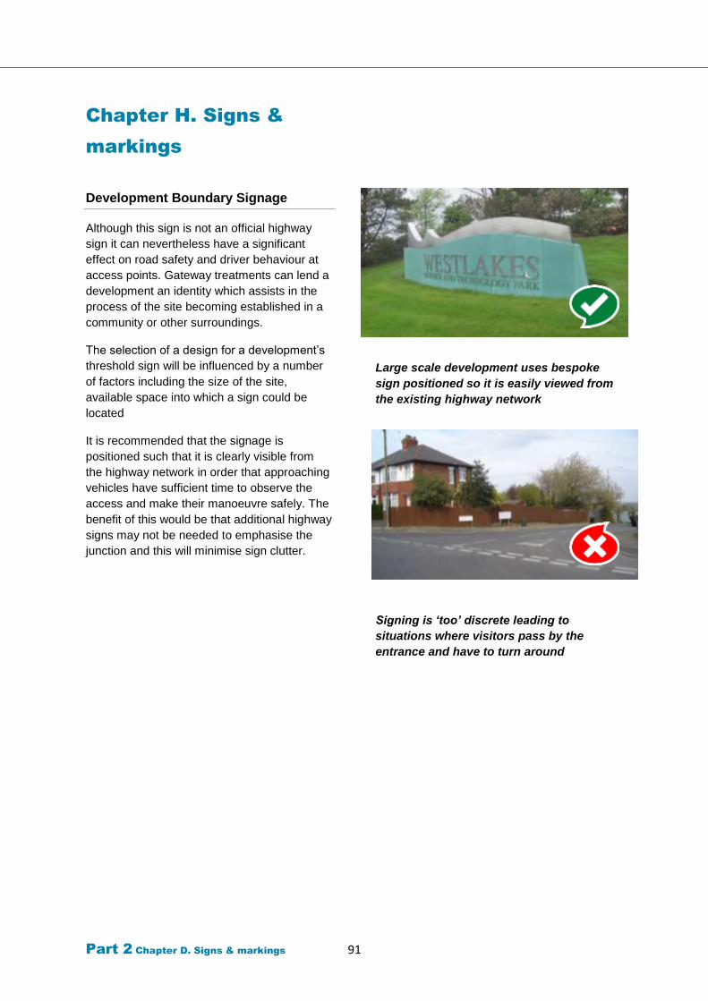
Part 2 Chapter D. Signs & markings 91
Chapter H. Signs &
markings
Development Boundary Signage
Although this sign is not an official highway
sign it can nevertheless have a significant
effect on road safety and driver behaviour at
access points. Gateway treatments can lend a
development an identity which assists in the
process of the site becoming established in a
community or other surroundings.
The selection of a design for a development’s
threshold sign will be influenced by a number
of factors including the size of the site,
available space into which a sign could be
located
It is recommended that the signage is
positioned such that it is clearly visible from
the highway network in order that approaching
vehicles have sufficient time to observe the
access and make their manoeuvre safely. The
benefit of this would be that additional highway
signs may not be needed to emphasise the
junction and this will minimise sign clutter.
Large scale development uses bespoke
sign positioned so it is easily viewed from
the existing highway network
Signing is ‘too’ discrete leading to
situations where visitors pass by the
entrance and have to turn around
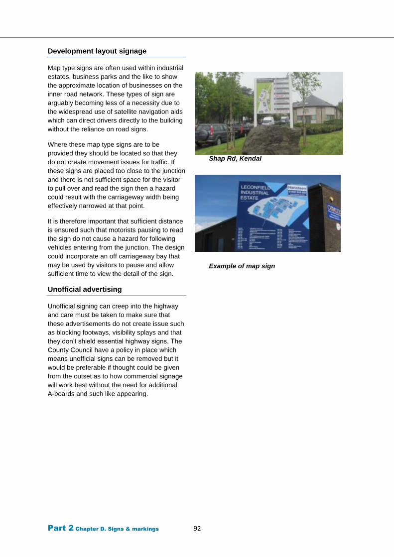
Part 2 Chapter D. Signs & markings 92
Development layout signage
Map type signs are often used within industrial
estates, business parks and the like to show
the approximate location of businesses on the
inner road network. These types of sign are
arguably becoming less of a necessity due to
the widespread use of satellite navigation aids
which can direct drivers directly to the building
without the reliance on road signs.
Where these map type signs are to be
provided they should be located so that they
do not create movement issues for traffic. If
these signs are placed too close to the junction
and there is not sufficient space for the visitor
to pull over and read the sign then a hazard
could result with the carriageway width being
effectively narrowed at that point.
It is therefore important that sufficient distance
is ensured such that motorists pausing to read
the sign do not cause a hazard for following
vehicles entering from the junction. The design
could incorporate an off carriageway bay that
may be used by visitors to pause and allow
sufficient time to view the detail of the sign.
Unofficial advertising
Unofficial signing can creep into the highway
and care must be taken to make sure that
these advertisements do not create issue such
as blocking footways, visibility splays and that
they don’t shield essential highway signs. The
County Council have a policy in place which
means unofficial signs can be removed but it
would be preferable if thought could be given
from the outset as to how commercial signage
will work best without the need for additional
A-boards and such like appearing.
Shap Rd, Kendal
Example of map sign
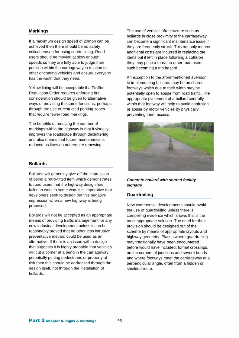
Part 2 Chapter D. Signs & markings 93
Markings
If a maximum design speed of 20mph can be
achieved then there should be no safety
critical reason for using centre lining. Road
users should be moving at slow enough
speeds so they are fully able to judge their
position within the carriageway in relation to
other oncoming vehicles and ensure everyone
has the width that they need.
Yellow lining will be acceptable if a Traffic
Regulation Order requires enforcing but
consideration should be given to alternative
ways of providing the same functions, perhaps
through the use of restricted parking zones
that require fewer road markings.
The benefits of reducing the number of
markings within the highway is that it visually
improves the roadscape through decluttering
and also means that future maintenance is
reduced as lines do not require renewing.
Bollards
Bollards will generally give off the impression
of being a retro-fitted item which demonstrates
to road users that the highway design has
failed to work in some way. It is imperative that
developers seek to design out this negative
impression when a new highway is being
proposed.
Bollards will not be accepted as an appropriate
means of providing traffic management for any
new industrial development unless it can be
reasonably proved that no other less intrusive
preventative method could be used as an
alternative. If there is an issue with a design
that suggests it is highly probable that vehicles
will cut a corner at a bend in the carriageway,
potentially putting pedestrians or property at
risk then this should be addressed through the
design itself, not through the installation of
bollards.
The use of vertical infrastructure such as
bollards in close proximity to the carriageway
can become a significant maintenance issue if
they are frequently struck. This not only means
additional costs are incurred in replacing the
items but if left in place following a collision
they may pose a threat to other road users
such becoming a trip hazard.
An exception to the aforementioned aversion
to implementing bollards may be on shared
footways which due to their width may be
potentially open to abuse from road traffic. The
appropriate placement of a bollard centrally
within that footway will help to avoid confusion
or abuse by motor vehicles by physically
preventing them access.
Concrete bollard with shared facility
signage
Guardrailing
New commercial developments should avoid
the use of guardrailing unless there is
compelling evidence which shows this is the
most appropriate solution. The need for their
provision should be designed out of the
scheme by means of appropriate layouts and
highway geometry. Places where guardrailing
may traditionally have been encountered
before would have included; formal crossings,
on the corners of junctions and severe bends
and where footways meet the carriageway at a
perpendicular angle, often from a hidden or
shielded route.
Part 2
Part 2 Chapter E. Parking 94
Chapter I. Sustainable
Travel
Travel plans
Cumbria County Council, as Highway and
Transport Authority, is keen to see Travel
Plans used effectively and will be working
towards this goal in partnership with Cumbria’s
Local Planning Authorities. Cumbria County
Council has the following guidance to assist
developers and their consultants to understand
when a travel plan will be required and the
expected content of the travel plan.
Travel Plans and the Planning Process in
Cumbria: Guidance for Developers
Travel plans form a fundamental part of the
development management process. It is
therefore a requirement that where
development proposals meet threshold levels,
or where a travel plan is specifically requested,
a travel plan is produced to accompany the
developer’s planning application. The most
applicable categories have been drawn out
and included here for quick viewing but the
more comprehensive list included the
aforementioned guidance should always be
checked regardless.
The main benefits of travel plans which are
applicable to the workplace include:
Reduction in parking cots
Saving costs on business travel
Tax relief
Improved access to work
Reduced congestion on commute
Improved travel choices
Improved company image
Healthier workforce
Travel plan measures will generally address
the following issues which will be key to
commercial developments:
Walking
Cycling
Public transport
Car Sharing
Working Practices
Car Parking Management
Promotion
Public Transport
Depending upon the scale of development
being provided it may be necessary to
incorporate bus stopping facilities within the
newly created highway. If it is desirable to
provide this service then designs should seek
to ensure infrastructure which has been
identified for that purpose is not adversely
affected by other road users.
Bus laybys for instance are often open to
abuse from unauthorised vehicles using them
as parking bays. If not properly enforced this
situation can continue and soon becomes the
norm rendering the initial design concept as a
failure. Laybys should only be provided if there
is a requirement for a Bus Stay as opposed to
a Bus Stop. A simple set down and pick up
arrangement from the kerbline of the
carriageway running lane should be sufficient
for this purpose and if flows are sufficiently low
enough then traffic will not be too adversely
affected.
Previously within this guide reference has
been made to the recommendation that buses
should not have to perform reversing
manoeuvres in order to navigate the
development.
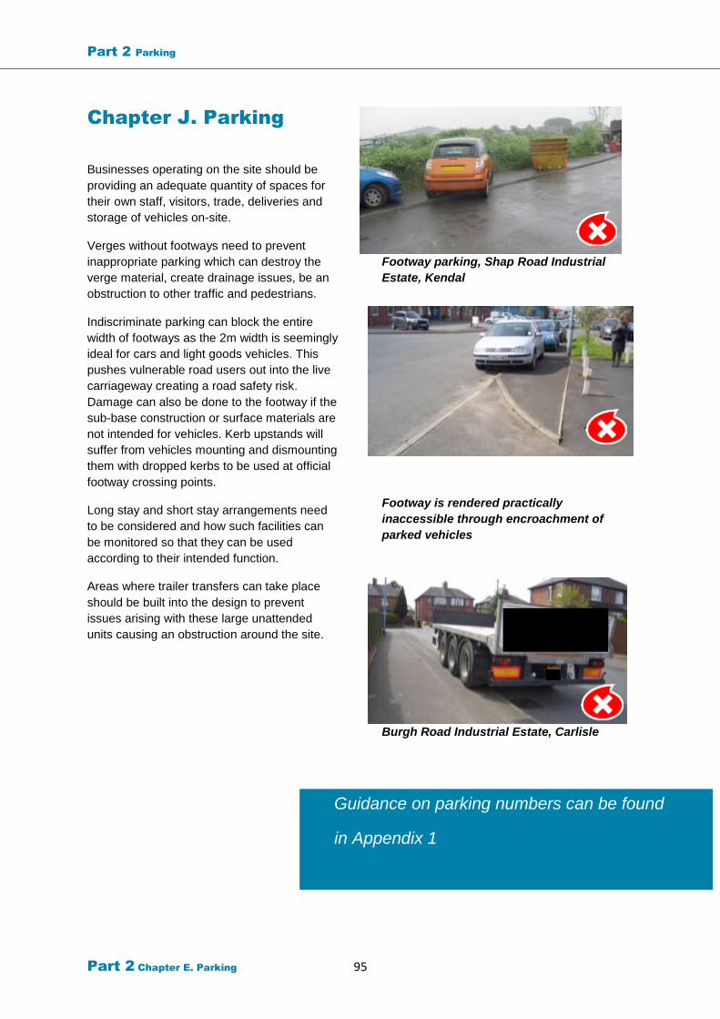
Part 2 Parking
Part 2 Chapter E. Parking 95
Guidance on parking numbers can be found
in Appendix 1
Chapter J. Parking
Businesses operating on the site should be
providing an adequate quantity of spaces for
their own staff, visitors, trade, deliveries and
storage of vehicles on-site.
Verges without footways need to prevent
inappropriate parking which can destroy the
verge material, create drainage issues, be an
obstruction to other traffic and pedestrians.
Indiscriminate parking can block the entire
width of footways as the 2m width is seemingly
ideal for cars and light goods vehicles. This
pushes vulnerable road users out into the live
carriageway creating a road safety risk.
Damage can also be done to the footway if the
sub-base construction or surface materials are
not intended for vehicles. Kerb upstands will
suffer from vehicles mounting and dismounting
them with dropped kerbs to be used at official
footway crossing points.
Long stay and short stay arrangements need
to be considered and how such facilities can
be monitored so that they can be used
according to their intended function.
Areas where trailer transfers can take place
should be built into the design to prevent
issues arising with these large unattended
units causing an obstruction around the site.
Footway parking, Shap Road Industrial
Estate, Kendal
Footway is rendered practically
inaccessible through encroachment of
parked vehicles
Burgh Road Industrial Estate, Carlisle
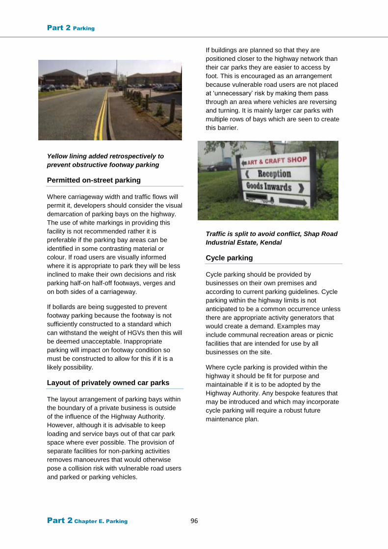
Part 2 Parking
Part 2 Chapter E. Parking 96
Yellow lining added retrospectively to
prevent obstructive footway parking
Permitted on-street parking
Where carriageway width and traffic flows will
permit it, developers should consider the visual
demarcation of parking bays on the highway.
The use of white markings in providing this
facility is not recommended rather it is
preferable if the parking bay areas can be
identified in some contrasting material or
colour. If road users are visually informed
where it is appropriate to park they will be less
inclined to make their own decisions and risk
parking half-on half-off footways, verges and
on both sides of a carriageway.
If bollards are being suggested to prevent
footway parking because the footway is not
sufficiently constructed to a standard which
can withstand the weight of HGVs then this will
be deemed unacceptable. Inappropriate
parking will impact on footway condition so
must be constructed to allow for this if it is a
likely possibility.
Layout of privately owned car parks
The layout arrangement of parking bays within
the boundary of a private business is outside
of the influence of the Highway Authority.
However, although it is advisable to keep
loading and service bays out of that car park
space where ever possible. The provision of
separate facilities for non-parking activities
removes manoeuvres that would otherwise
pose a collision risk with vulnerable road users
and parked or parking vehicles.
If buildings are planned so that they are
positioned closer to the highway network than
their car parks they are easier to access by
foot. This is encouraged as an arrangement
because vulnerable road users are not placed
at ‘unnecessary’ risk by making them pass
through an area where vehicles are reversing
and turning. It is mainly larger car parks with
multiple rows of bays which are seen to create
this barrier.
Traffic is split to avoid conflict, Shap Road
Industrial Estate, Kendal
Cycle parking
Cycle parking should be provided by
businesses on their own premises and
according to current parking guidelines. Cycle
parking within the highway limits is not
anticipated to be a common occurrence unless
there are appropriate activity generators that
would create a demand. Examples may
include communal recreation areas or picnic
facilities that are intended for use by all
businesses on the site.
Where cycle parking is provided within the
highway it should be fit for purpose and
maintainable if it is to be adopted by the
Highway Authority. Any bespoke features that
may be introduced and which may incorporate
cycle parking will require a robust future
maintenance plan.

Part 2 Chapter G. Lighting 97
Chapter K. Utility
services
The advice from Design Guide should also be
applied to commercial developments with a
particular emphasis on early engagement
between developer and utility companies
recommended. There should be no services
placed within the constraints of the
carriageway and should instead be kept within
the margins of available footways or allocated
maintenance strips.
Part 2 Chapter G. Lighting 98
Chapter L. Lighting
Cumbria County Council’s Road Lighting
Policy 2014 sets out the following objectives
for the provision and maintenance of road
lighting:
to provide a safe network for all highway
users, taking into account the needs of
more vulnerable groups, but with the
principal aim of reducing night-time
accidents.
to maintain lighting to a standard which
ensures as far as possible a safe,
economic, effective and reliable use of
the highway during the hours of darkness.
to contribute to crime reduction strategies
by improving lighting where funding is
available in order to provide a safer night-
time environment.
to contribute to the economic well-being
of the County by helping transport
movements and enhancing the night-time
environment of urban areas, including
tourist centres.
to protect the night-time environment by
setting levels of lighting provision which
reflect the variety and diversity of the
County
The policy also includes a guide to the kind of
lighting requirements which would be expected
for application in different character areas
found within Cumbria. These areas range from
rural settlements within National Parks to
larger urban areas.
The need to provide road lighting throughout
the hours of darkness will depend upon the
requirements of the businesses within the
commercial development. Those that require
access around the clock may benefit from a lit
carriageway, particularly if employees working
shifts are arriving and leaving by foot or cycle.
The presence of trees can have an impact on
the effectiveness of lighting in terms of the
blockage of light or structural damage that may
occur to the unit. The placement of new
lighting columns in the vicinity of existing trees
or the introduction of new trees as part of a
landscaping plan must be assessed thoroughly
and the lighting design should therefore be
carried out in consultation with landscape
architects or suitable qualified professionals.
Keeping lighting columns at the back of
footways not only helps with keeping through
routes clear for pedestrians and cyclists where
shared facilities are used, but also lessens the
opportunities for vehicles to collide with them
which can be a real concern with the presence
of long or oversize vehicles with significant
overhangs.
Further detailed guidance can be found in
Appendix 10.
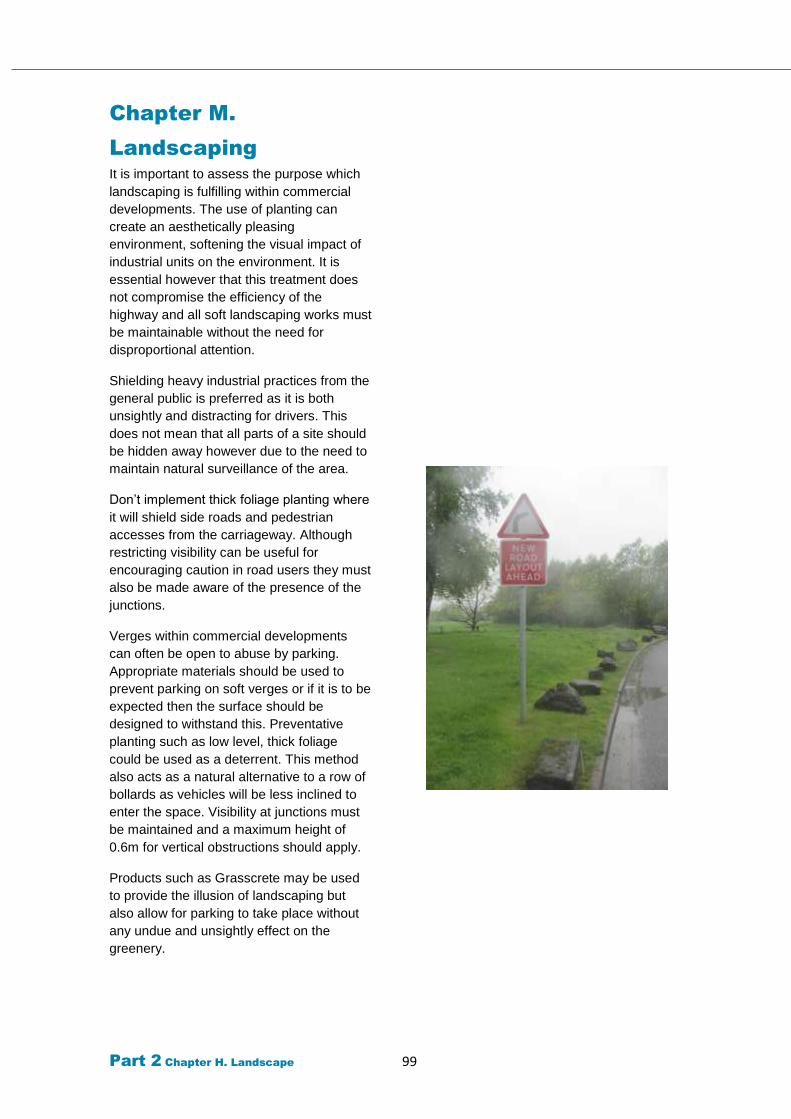
Part 2 Chapter H. Landscape 99
Chapter M.
Landscaping
It is important to assess the purpose which
landscaping is fulfilling within commercial
developments. The use of planting can
create an aesthetically pleasing
environment, softening the visual impact of
industrial units on the environment. It is
essential however that this treatment does
not compromise the efficiency of the
highway and all soft landscaping works must
be maintainable without the need for
disproportional attention.
Shielding heavy industrial practices from the
general public is preferred as it is both
unsightly and distracting for drivers. This
does not mean that all parts of a site should
be hidden away however due to the need to
maintain natural surveillance of the area.
Don’t implement thick foliage planting where
it will shield side roads and pedestrian
accesses from the carriageway. Although
restricting visibility can be useful for
encouraging caution in road users they must
also be made aware of the presence of the
junctions.
Verges within commercial developments
can often be open to abuse by parking.
Appropriate materials should be used to
prevent parking on soft verges or if it is to be
expected then the surface should be
designed to withstand this. Preventative
planting such as low level, thick foliage
could be used as a deterrent. This method
also acts as a natural alternative to a row of
bollards as vehicles will be less inclined to
enter the space. Visibility at junctions must
be maintained and a maximum height of
0.6m for vertical obstructions should apply.
Products such as Grasscrete may be used
to provide the illusion of landscaping but
also allow for parking to take place without
any undue and unsightly effect on the
greenery.
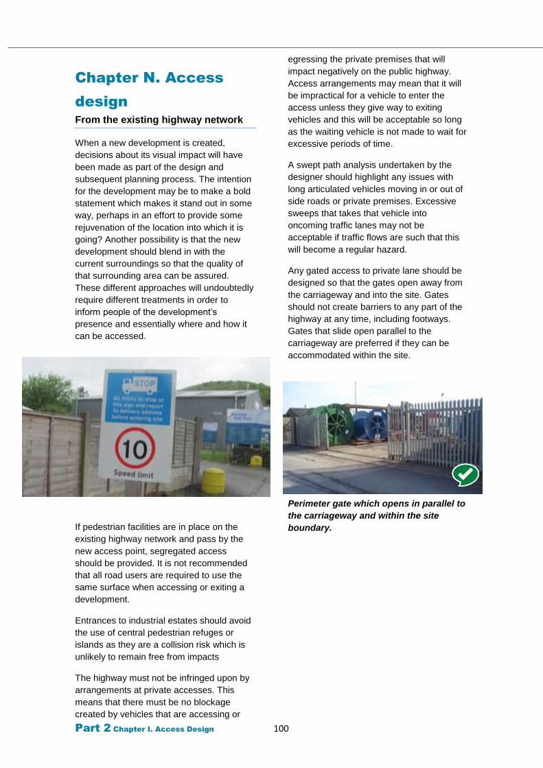
Part 2 Chapter I. Access Design 100
Chapter N. Access
design
From the existing highway network
When a new development is created,
decisions about its visual impact will have
been made as part of the design and
subsequent planning process. The intention
for the development may be to make a bold
statement which makes it stand out in some
way, perhaps in an effort to provide some
rejuvenation of the location into which it is
going? Another possibility is that the new
development should blend in with the
current surroundings so that the quality of
that surrounding area can be assured.
These different approaches will undoubtedly
require different treatments in order to
inform people of the development’s
presence and essentially where and how it
can be accessed.
If pedestrian facilities are in place on the
existing highway network and pass by the
new access point, segregated access
should be provided. It is not recommended
that all road users are required to use the
same surface when accessing or exiting a
development.
Entrances to industrial estates should avoid
the use of central pedestrian refuges or
islands as they are a collision risk which is
unlikely to remain free from impacts
The highway must not be infringed upon by
arrangements at private accesses. This
means that there must be no blockage
created by vehicles that are accessing or
egressing the private premises that will
impact negatively on the public highway.
Access arrangements may mean that it will
be impractical for a vehicle to enter the
access unless they give way to exiting
vehicles and this will be acceptable so long
as the waiting vehicle is not made to wait for
excessive periods of time.
A swept path analysis undertaken by the
designer should highlight any issues with
long articulated vehicles moving in or out of
side roads or private premises. Excessive
sweeps that takes that vehicle into
oncoming traffic lanes may not be
acceptable if traffic flows are such that this
will become a regular hazard.
Any gated access to private lane should be
designed so that the gates open away from
the carriageway and into the site. Gates
should not create barriers to any part of the
highway at any time, including footways.
Gates that slide open parallel to the
carriageway are preferred if they can be
accommodated within the site.
Perimeter gate which opens in parallel to
the carriageway and within the site
boundary.
Part 2 Chapter I. Access Design 101
Chapter O. Mixed Use
sites
Commercial developments are able to
accommodate a great range of business
activity within them from small workshop
based enterprises to large scale industrial
complexes. If discrete areas are intended for
the sole purpose of the smaller scale business
units such as those which are based around a
courtyard parking arrangement, then these
areas may benefit from their access point
being treated differently to the rest of the
highway.
Some form of raised entry could perhaps
provide the necessary visual clue that HGVs
should not be entering that space. This raised
access would also prove beneficial to
pedestrians and cyclists who would be able to
use the feature as a crossing without the need
for dropped kerbs.
Various other methods could be used to
provide this visual deterrent to larger vehicles
using the development but the use of signs
that give a warning or prohibition message
should not be the preferred solution. Physical
design options should be used first and
foremost to allow a self –enforcement of the
access arrangement and a TRO should only
be considered as a last resort or if a problem
persists. The creation of restricted zones can
mean a reduction is yellow lining as vehicles
can only use marked bays within a zone and
those bays can and preferably should be
marked out by a method other than painted
white markings.
If visibility is good between the side road area
and the other road then it may be possible to
use a single vehicle width entry/exit where
vehicles would be forced into giving way to
one another to allow for access and egress.
This arrangement would act as a deterrent to
large vehicles attempting to enter the space
and would create traffic calming for other
vehicles at the access. The use of such a
design would be subject to anticipated traffic
volumes using the access and any knock on
effect that queuing traffic would have on the
main road.
It is important to note
that if loading must
take place within this
courtyard area then
HGVs may still enter
but only those that
have a direct reason
for visiting the site
Recommended