MAN B&W Low Speed Small Bore EnginesNow with Electronic Control

Contents
Introduction .................................................................................................5
Engine data ............................................................................................7
Engine comparison .................................................................................8
ME-B fuel injection control system .............................................................. 10
Injection performance ........................................................................... 10
Engine control system ........................................................................... 11
Engine Design S35/40/50ME-B .................................................................. 12
Bedplate, framebox and cylinder frame ................................................. 12
Crankshaft ............................................................................................ 14
Connecting rod ..................................................................................... 14
Bearings ............................................................................................... 15
Combustion chamber ........................................................................... 15
Cylinder liner ......................................................................................... 15
Piston ................................................................................................... 16
Exhaust valve ....................................................................................... 17
Fuel injection equipment ....................................................................... 17
Thrust bearing ...................................................................................... 18
Engine control system ........................................................................... 19
Turbocharger and air cooler arrangement .............................................. 19
Concluding Remarks .................................................................................. 20

MAN B&W Low Speed Small Bore Engines – Now with Electronic Control 5
MAN B&W Low Speed Small Bore Engines Now with Electronic Control
Introduction
The MAN B&W 35MC engine was
launched in 1982 as the L35MC with
500 kW/cylinder and a mean effective
pressure of 14.8 bar at 200 rpm. Sev-
eral design updates, often combined
with a power up, have been introduced
since then, and with today’s Mark 6 rat-
ing, the power per cylinder is 650 kW/
cylinder with a mean pressure of 18.4
bar at 210 rpm.
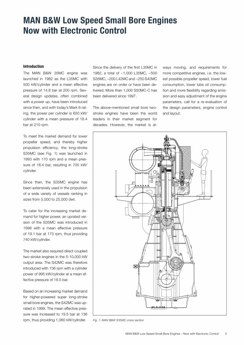
To meet the market demand for lower
propeller speed, and thereby higher
propulsion efficiency, the long-stroke
S35MC (see Fig. 1) was launched in
1993 with 170 rpm and a mean pres-
sure of 18.4 bar, resulting in 700 kW/
cylinder.
Since then, the S35MC engine has
been extensively used in the propulsion
of a wide variety of vessels ranking in
sizes from 5,000 to 25,000 dwt.
To cater for the increasing market de-
mand for higher power, an uprated ver-
sion of the S35MC was introduced in
1998 with a mean effective pressure
of 19.1 bar at 173 rpm, thus providing
740 kW/cylinder.
The market also required direct coupled
two-stroke engines in the 5-10,000 kW
output area. The S42MC was therefore
introduced with 136 rpm with a cylinder
power of 995 kW/cylinder at a mean ef-
fective pressure of 18.5 bar.
Based on an increasing market demand
for higher-powered super long-stroke
small bore engines, the S42MC was up-
rated in 1999. The mean effective pres-
sure was increased to 19.5 bar at 136
rpm, thus providing 1,060 kW/cylinder.
Since the delivery of the first L35MC in
1982, a total of ~1,000 L35MC, ~500
S35MC, ~200 L42MC and ~250 S42MC
engines are on order or have been de-
livered. More than 1,000 S50MC-C has
been delivered since 1997.
The above-mentioned small bore two-
stroke engines have been the world
leaders in their market segment for
decades. However, the market is al-
ways moving, and requirements for
more competitive engines, i.e. the low-
est possible propeller speed, lower fuel
consumption, lower lube oil consump-
tion and more flexibility regarding emis-
sion and easy adjustment of the engine
parameters, call for a re-evaluation of
the design parameters, engine control
and layout.
Fig. 1: MAN B&W S35MC cross section
MAN B&W Low Speed Small Bore Engines – Now with Electronic Control6
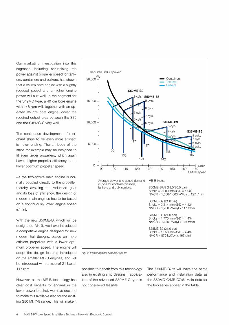
Our marketing investigation into this
segment, including scrutinising the
power against propeller speed for tank-
ers, containers and bulkers, has shown
that a 35 cm bore engine with a slightly
reduced speed and a higher engine
power will suit well. In the segment for
the S42MC type, a 40 cm bore engine
with 146 rpm will, together with an up-
dated 35 cm bore engine, cover the
required output area between the S35
and the S46MC-C very well,
The continuous development of mer-
chant ships to be even more efficient
is never ending. The aft body of the
ships for example may be designed to
fit even larger propellers, which again
have a higher propeller efficiency, but a
lower optimum propeller speed.
As the two-stroke main engine is nor-
mally coupled directly to the propeller,
thereby avoiding the reduction gear
and its loss of efficiency, the design of
modern main engines has to be based
on a continuously lower engine speed
(r/min).
With the new S50ME-B, which will be
designated Mk 9, we have introduced
a competitive engine designed for new
modern hull designs, based on more
efficient propellers with a lower opti-
mum propeller speed. The engine will
adopt the design features introduced
on the smaller ME-B engines, and will
be introduced with a mep of 21 bar at
117 rpm.
However, as the ME-B technology has
clear cost benefits for engines in the
lower power bracket, we have decided
to make this available also for the exist-
ing S50 Mk 7/8 range. This will make it
possible to benefit from this technology
also in existing ship designs if applica-
tion of the advanced S50ME-C type is
not considered feasible.
The S50ME-B7/8 will have the same
performance and installation data as
the S50MC-C/ME-C7/8. Main data for
the two series appear in the table.
kWRequired SMCR power
170160150140130120100SMCR speed
0
5,000
10,000
20,000
110
15,000
90
117
99
S50ME-B9
127
108
S50ME-B8
8 cyls.S40ME-B9
7 cyls.
6 cyls.
5 cyls.
146
124
8 cyls.7 cyls.6 cyls.
167142
S35ME-B9
5 cyls.
TankersContainers
Bulkers
Average power and speed demandcurves for container vessels,tankers and bulk carriers:
ME-B types:
S50ME-B7/8 (19.0/20.0 bar) Stroke = 2,000 mm (S/D = 4.00)NMCR = 1,580/1,660 kW/cyl x 127 r/min
S50ME-B9 (21.0 bar) Stroke = 2,214 mm (S/D = 4.43)NMCR = 1,780 kW/cyl x 117 r/min
S40ME-B9 (21.0 bar) Stroke = 1,770 mm (S/D = 4.43)NMCR = 1,135 kW/cyl x 146 r/min
S35ME-B9 (21.0 bar) Stroke = 1,550 mm (S/D = 4.43)NMCR = 870 kW/cyl x 167 r/min
r/min
7 cyls.
8 cyls.
6 cyls.
5 cyls.
9 cyls.
7 cyls.
8 cyls.
6 cyls.
5 cyls.
9 cyls.
Fig. 2: Power against propeller speed
MAN B&W Low Speed Small Bore Engines – Now with Electronic Control 7
Both types will also be available in con-
ventional turbocharger versions with
+2g/kWh higher SFOC, respectively.
The layout diagram of the ME-B9 en-
gine types, superimposed on the ex-
pected combination of speed and
power of the target ship groups; con-
tainer ships, tankers and bulk carriers,
are shown in the enclosure.
The S50ME-B7/8 and 9 engines will be
available in configurations of five to nine
cylinders.
In addition, the market acceptance of
electronically controlled engines is now
turning into a market demand. There-
fore, the new engine with a future elec-
tronic fuel system control will be desig-
nated ME-B, i.e. S35ME-B, S40ME-B
and S50ME-B respectively.
Engine data
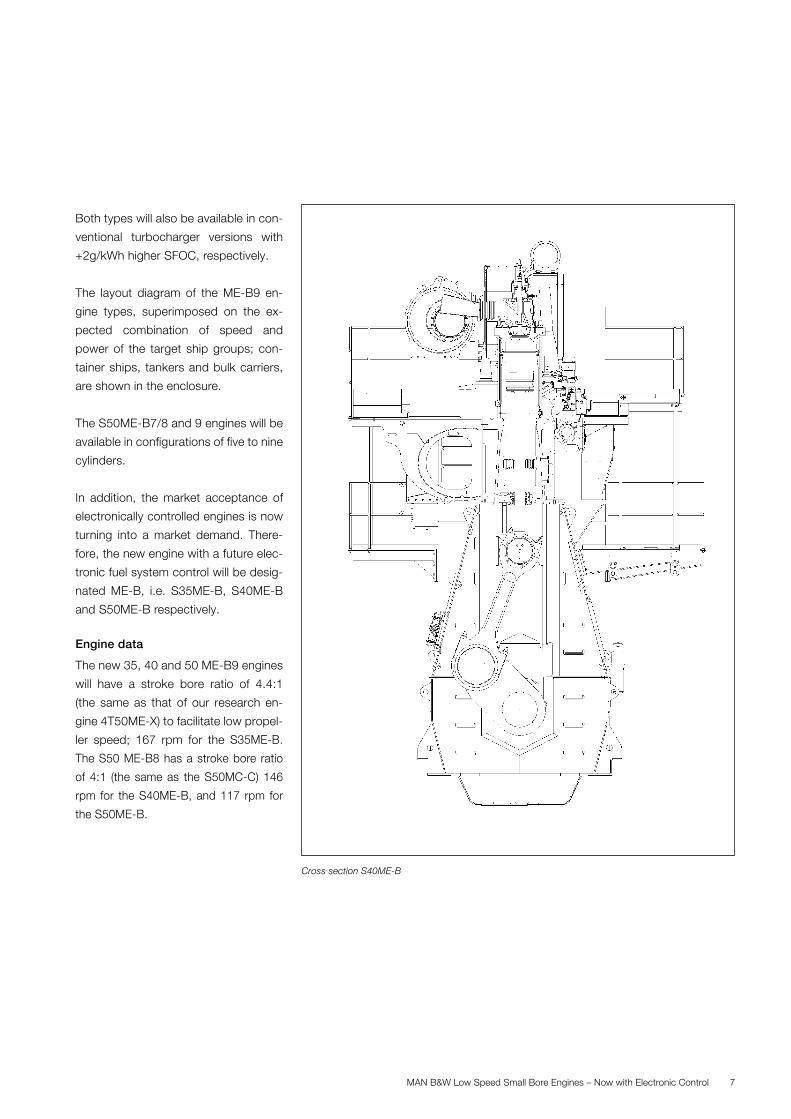
The new 35, 40 and 50 ME-B9 engines
will have a stroke bore ratio of 4.4:1
(the same as that of our research en-
gine 4T50ME-X) to facilitate low propel-
ler speed; 167 rpm for the S35ME-B.
The S50 ME-B8 has a stroke bore ratio
of 4:1 (the same as the S50MC-C) 146
rpm for the S40ME-B, and 117 rpm for
the S50ME-B.
Cross section S40ME-B
MAN B&W Low Speed Small Bore Engines – Now with Electronic Control8
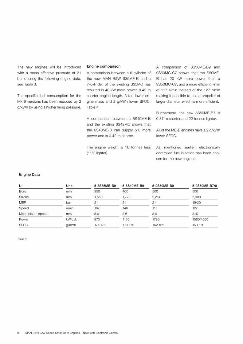
The new engines will be introduced
with a mean effective pressure of 21
bar offering the following engine data,
see Table 3.
The specific fuel consumption for the
Mk 9 versions has been reduced by 2
g/kWh by using a higher firing pressure.
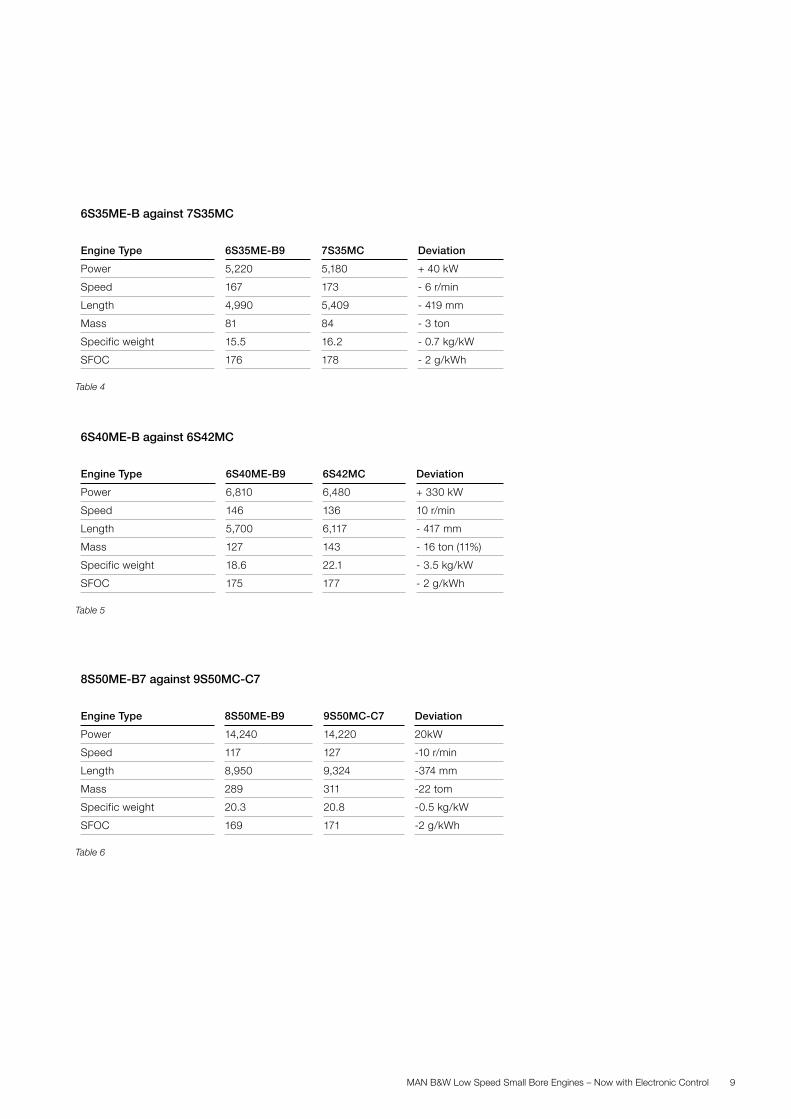
Engine comparison
A comparison between a 6-cylinder of
the new MAN B&W S35ME-B and a
7-cylinder of the existing S35MC has
resulted in 40 kW more power, 0.42 m
shorter engine length, 3 ton lower en-
gine mass and 2 g/kWh lower SFOC,
Table 4.
A comparison between a 6S40ME-B
and the existing 6S42MC shows that
the 6S40ME-B can supply 5% more
power and is 0.42 m shorter.
The engine weight is 16 tonnes less
(11% lighter).
A comparison of 8S50ME-B9 and
9S50MC-C7 shows that the S50ME-
B has 20 kW more power than a
9S50MC-C7, and a more efficient r/min
of 117 r/min instead of the 127 r/min
making it possible to use a propeller of
larger diameter which is more efficient.
Furthermore, the new 8S50ME-B7 is
0.37 m shorter and 22 tonnes lighter.
All of the ME-B engines have a 2 g/kWh
lower SFOC.
As mentioned earlier, electronically
controlled fuel injection has been cho-
sen for the new engines.
Engine Data
L1 Unit 5-8S35ME-B9 5-8S40ME-B9 5-9S50ME-B9 5-9S50ME-B7/8
Bore mm 350 400 500 500
Stroke mm 1,550 1,770 2,214 2,000
MEP bar 21 21 21 19/20
Speed r/min 167 146 117 127
Mean piston speed m/s 8.6 8.6 8.6 8.47
Power kW/cyl. 870 1135 1780 1580/1660
SFOC g/kWh 171-176 170-175 162-169 159-170
Table 3
MAN B&W Low Speed Small Bore Engines – Now with Electronic Control 9
6S35ME-B against 7S35MC
Engine Type 6S35ME-B9 7S35MC Deviation
Power 5,220 5,180 + 40 kW
Speed 167 173 - 6 r/min
Length 4,990 5,409 - 419 mm
Mass 81 84 - 3 ton
Specific weight 15.5 16.2 - 0.7 kg/kW
SFOC 176 178 - 2 g/kWh
Table 4
6S40ME-B against 6S42MC
Engine Type 6S40ME-B9 6S42MC Deviation
Power 6,810 6,480 + 330 kW
Speed 146 136 10 r/min
Length 5,700 6,117 - 417 mm
Mass 127 143 - 16 ton (11%)
Specific weight 18.6 22.1 - 3.5 kg/kW
SFOC 175 177 - 2 g/kWh
Table 5
8S50ME-B7 against 9S50MC-C7
Engine Type 8S50ME-B9 9S50MC-C7 Deviation
Power 14,240 14,220 20kW
Speed 117 127 -10 r/min
Length 8,950 9,324 -374 mm
Mass 289 311 -22 tom
Specific weight 20.3 20.8 -0.5 kg/kW
SFOC 169 171 -2 g/kWh
Table 6
MAN B&W Low Speed Small Bore Engines – Now with Electronic Control10
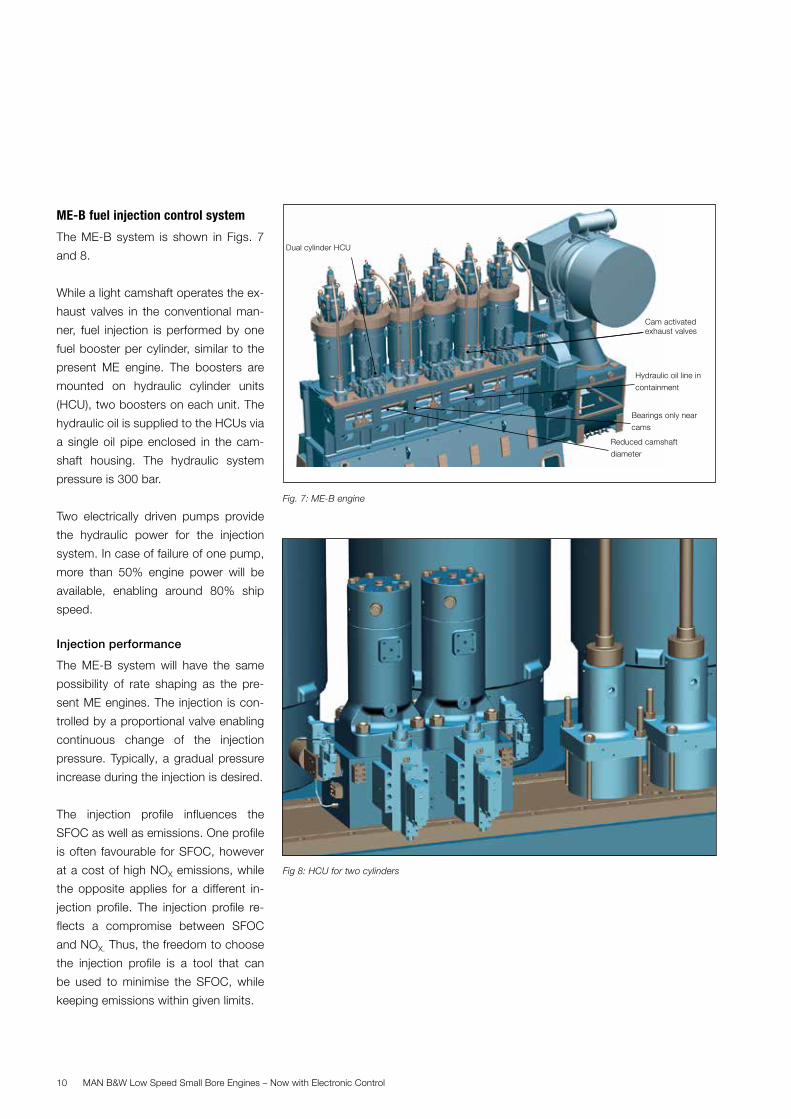
ME-B fuel injection control system
The ME-B system is shown in Figs. 7
and 8.
While a light camshaft operates the ex-
haust valves in the conventional man-
ner, fuel injection is performed by one
fuel booster per cylinder, similar to the
present ME engine. The boosters are
mounted on hydraulic cylinder units
(HCU), two boosters on each unit. The
hydraulic oil is supplied to the HCUs via
a single oil pipe enclosed in the cam-
shaft housing. The hydraulic system
pressure is 300 bar.
Two electrically driven pumps provide
the hydraulic power for the injection
system. In case of failure of one pump,
more than 50% engine power will be
available, enabling around 80% ship
speed.
Injection performance
The ME-B system will have the same
possibility of rate shaping as the pre-
sent ME engines. The injection is con-
trolled by a proportional valve enabling
continuous change of the injection
pressure. Typically, a gradual pressure
increase during the injection is desired.
The injection profile influences the
SFOC as well as emissions. One profile
is often favourable for SFOC, however
at a cost of high NOX emissions, while
the opposite applies for a different in-
jection profile. The injection profile re-
flects a compromise between SFOC
and NOX. Thus, the freedom to choose
the injection profile is a tool that can
be used to minimise the SFOC, while
keeping emissions within given limits.
Fig 8: HCU for two cylinders
Fig. 7: ME-B engine
Cam activated exhaust valves
Dual cylinder HCU
Reduced camshaft
diameter
Bearings only near
cams
Hydraulic oil line in
containment
MAN B&W Low Speed Small Bore Engines – Now with Electronic Control 11
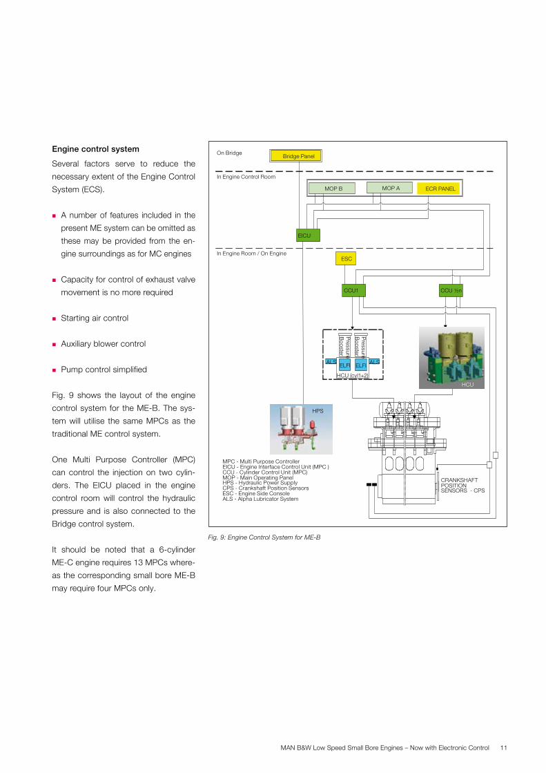
Engine control system
Several factors serve to reduce the
necessary extent of the Engine Control
System (ECS).
� A number of features included in the
present ME system can be omitted as
these may be provided from the en-
gine surroundings as for MC engines
� Capacity for control of exhaust valve
movement is no more required
� Starting air control
� Auxiliary blower control
� Pump control simplified
Fig. 9 shows the layout of the engine
control system for the ME-B. The sys-
tem will utilise the same MPCs as the
traditional ME control system.
One Multi Purpose Controller (MPC)
can control the injection on two cylin-
ders. The EICU placed in the engine
control room will control the hydraulic
pressure and is also connected to the
Bridge control system.
It should be noted that a 6-cylinder
ME-C engine requires 13 MPCs where-
as the corresponding small bore ME-B
may require four MPCs only.
Fig. 9: Engine Control System for ME-B
CRANKSHAFTPOSITIONSENSORS - CPS
CCU1
MPC - Multi Purpose ControllerEICU - Engine Interface Control Unit (MPC )CCU - Cylinder Control Unit (MPC) MOP - Main Operating PanelHPS - Hydraulic Power SupplyCPS - Crankshaft Position Sensors ESC - Engine Side ConsoleALS - Alpha Lubricator System
MOP A
ELFI ELFIALSALS
HCU (cyl1+2)
MOP B
EICU
CCU ½n
Pressure
Booster
Pressure
Booster
On Bridge
In Engine Control Room
In Engine Room / On Engine
Bridge Panel
ESC
ECR PANEL
HPS
HCU
MAN B&W Low Speed Small Bore Engines – Now with Electronic Control12
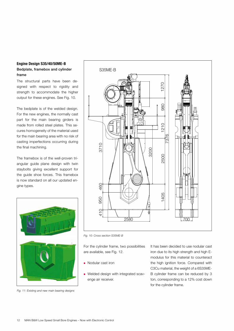
Engine Design S35/40/50ME-BBedplate, framebox and cylinder
frame
The structural parts have been de-
signed with respect to rigidity and
strength to accommodate the higher
output for these engines. See Fig. 10.
The bedplate is of the welded design.
For the new engines, the normally cast
part for the main bearing girders is
made from rolled steel plates. This se-
cures homogeneity of the material used
for the main bearing area with no risk of
casting imperfections occurring during
the final machining.
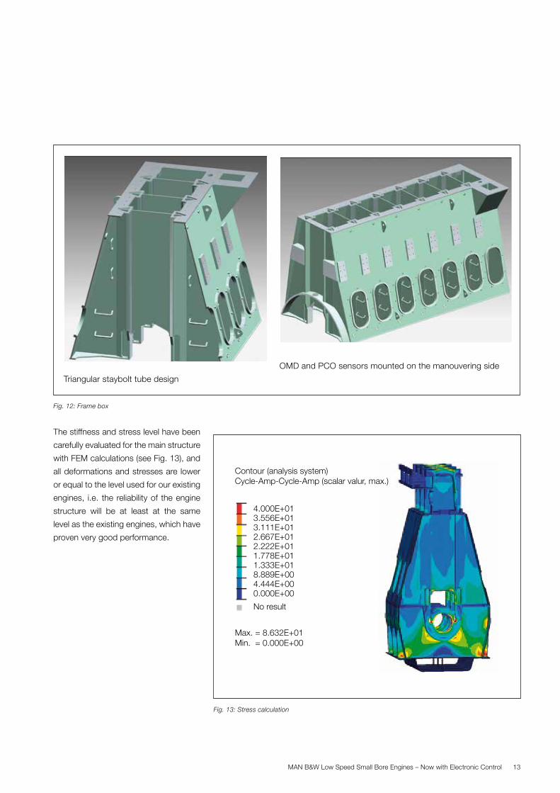
The framebox is of the well-proven tri-
angular guide plane design with twin
staybolts giving excellent support for
the guide shoe forces. This framebox
is now standard on all our updated en-
gine types.
For the cylinder frame, two possibilities
are available, see Fig. 12.
� Nodular cast iron
� Welded design with integrated scav-
enge air receiver.
It has been decided to use nodular cast
iron due to its high strength and high E-
modulus for this material to counteract
the high ignition force. Compared with
C3Cu material, the weight of a 6S35ME-
B cylinder frame can be reduced by 3
ton, corresponding to a 12% cost down
for the cylinder frame.
Fig. 10: Cross section S35ME-B
S35ME-B
46
09
50
700
12
10
14
05
2580
98
02
50
0
37
10
12
70
32
00
73
76
41
0
Fig. 11: Existing and new main bearing designs
MAN B&W Low Speed Small Bore Engines – Now with Electronic Control 13
The stiffness and stress level have been
carefully evaluated for the main structure
with FEM calculations (see Fig. 13), and
all deformations and stresses are lower
or equal to the level used for our existing
engines, i.e. the reliability of the engine
structure will be at least at the same
level as the existing engines, which have
proven very good performance.
Fig. 12: Frame box
OMD and PCO sensors mounted on the manouvering side
Triangular staybolt tube design
Fig. 13: Stress calculation
4.000E+013.556E+013.111E+012.667E+012.222E+011.778E+011.333E+018.889E+004.444E+000.000E+00
No result
Contour (analysis system)Cycle-Amp-Cycle-Amp (scalar valur, max.)
Max. = 8.632E+01Min. = 0.000E+00
MAN B&W Low Speed Small Bore Engines – Now with Electronic Control14
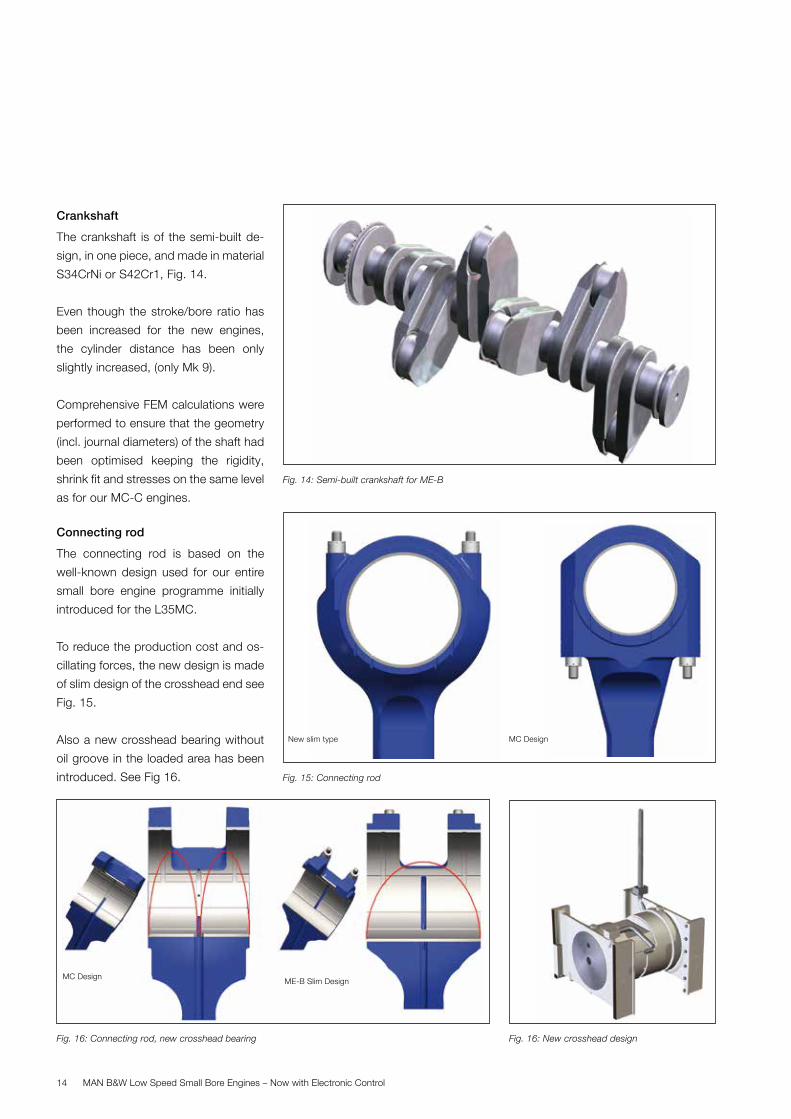
Crankshaft
The crankshaft is of the semi-built de-
sign, in one piece, and made in material
S34CrNi or S42Cr1, Fig. 14.
Even though the stroke/bore ratio has
been increased for the new engines,
the cylinder distance has been only
slightly increased, (only Mk 9).
Comprehensive FEM calculations were
performed to ensure that the geometry
(incl. journal diameters) of the shaft had
been optimised keeping the rigidity,
shrink fit and stresses on the same level
as for our MC-C engines.
Connecting rod
The connecting rod is based on the
well-known design used for our entire
small bore engine programme initially
introduced for the L35MC.
To reduce the production cost and os-
cillating forces, the new design is made
of slim design of the crosshead end see
Fig. 15.
Also a new crosshead bearing without
oil groove in the loaded area has been
introduced. See Fig 16.
Fig. 14: Semi-built crankshaft for ME-B
Fig. 16: New crosshead design
Fig. 15: Connecting rod
Fig. 16: Connecting rod, new crosshead bearing
ME-B Slim Design
MC Design New slim type
MC Design
MAN B&W Low Speed Small Bore Engines – Now with Electronic Control 15
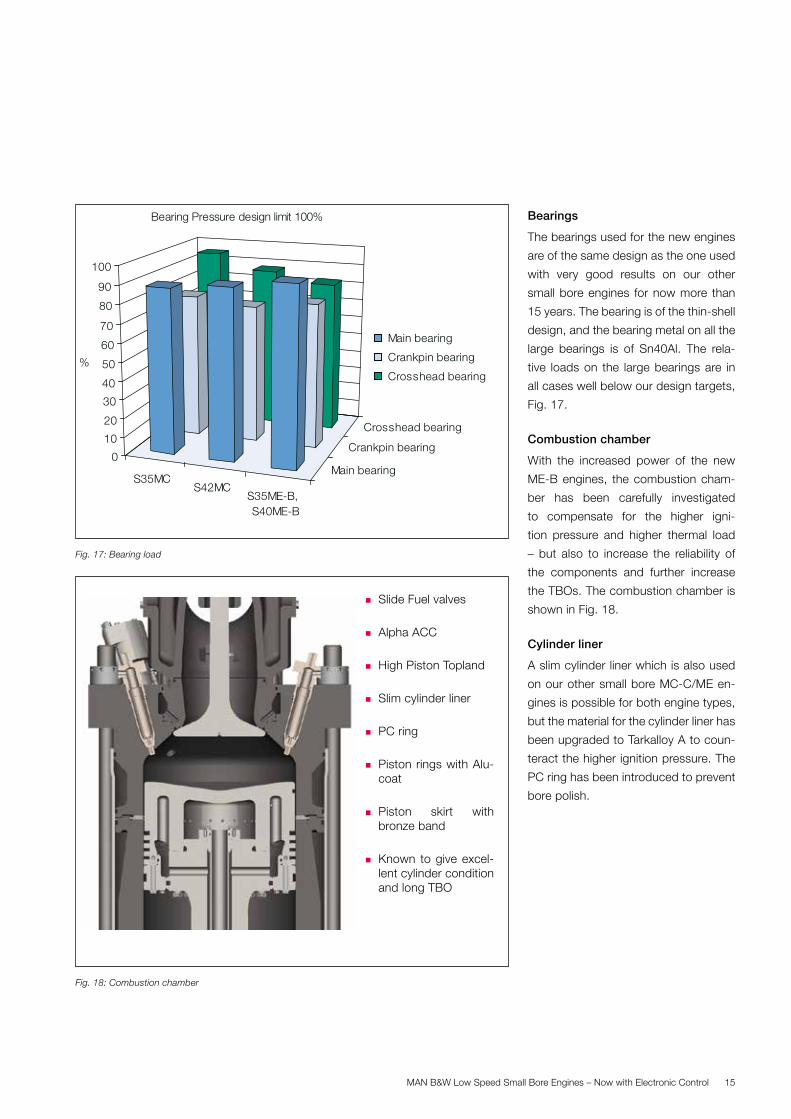
Bearings
The bearings used for the new engines
are of the same design as the one used
with very good results on our other
small bore engines for now more than
15 years. The bearing is of the thin-shell
design, and the bearing metal on all the
large bearings is of Sn40Al. The rela-
tive loads on the large bearings are in
all cases well below our design targets,
Fig. 17.
Combustion chamber
With the increased power of the new
ME-B engines, the combustion cham-
ber has been carefully investigated
to compensate for the higher igni-
tion pressure and higher thermal load
– but also to increase the reliability of
the components and further increase
the TBOs. The combustion chamber is
shown in Fig. 18.
Cylinder liner
A slim cylinder liner which is also used
on our other small bore MC-C/ME en-
gines is possible for both engine types,
but the material for the cylinder liner has
been upgraded to Tarkalloy A to coun-
teract the higher ignition pressure. The
PC ring has been introduced to prevent
bore polish.
Fig. 17: Bearing load
S35MCS42MC
S35ME-B, S40ME-B
Main bearing
Crankpin bearing
Crosshead bearing
0
10
20
30
40
50
60
70
80
90
100
%
Bearing Pressure design limit 100%
Main bearing
Crankpin bearing
Crosshead bearing
Fig. 18: Combustion chamber
� Slide Fuel valves
� Alpha ACC
� High Piston Topland
� Slim cylinder liner
� PC ring
� Piston rings with Alu-coat
� Piston skirt with bronze band
� Known to give excel-lent cylinder condition and long TBO
MAN B&W Low Speed Small Bore Engines – Now with Electronic Control16
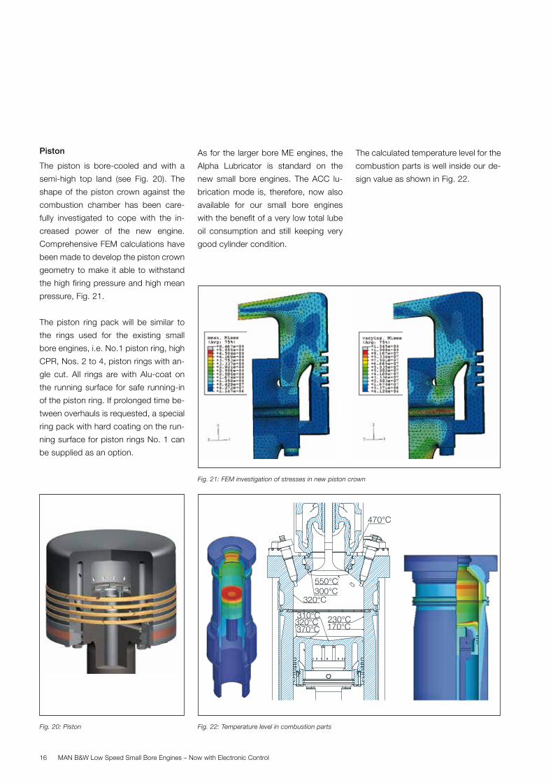
Piston
The piston is bore-cooled and with a
semi-high top land (see Fig. 20). The
shape of the piston crown against the
combustion chamber has been care-
fully investigated to cope with the in-
creased power of the new engine.
Comprehensive FEM calculations have
been made to develop the piston crown
geometry to make it able to withstand
the high firing pressure and high mean
pressure, Fig. 21.
The piston ring pack will be similar to
the rings used for the existing small
bore engines, i.e. No.1 piston ring, high
CPR, Nos. 2 to 4, piston rings with an-
gle cut. All rings are with Alu-coat on
the running surface for safe running-in
of the piston ring. If prolonged time be-
tween overhauls is requested, a special
ring pack with hard coating on the run-
ning surface for piston rings No. 1 can
be supplied as an option.
As for the larger bore ME engines, the
Alpha Lubricator is standard on the
new small bore engines. The ACC lu-
brication mode is, therefore, now also
available for our small bore engines
with the benefit of a very low total lube
oil consumption and still keeping very
good cylinder condition.
The calculated temperature level for the
combustion parts is well inside our de-
sign value as shown in Fig. 22.
Fig. 22: Temperature level in combustion parts
470°C
550°C300°C
230°C170°C
320°C
320°C370°C
310°C
Fig. 21: FEM investigation of stresses in new piston crown
Fig. 20: Piston
MAN B&W Low Speed Small Bore Engines – Now with Electronic Control 17
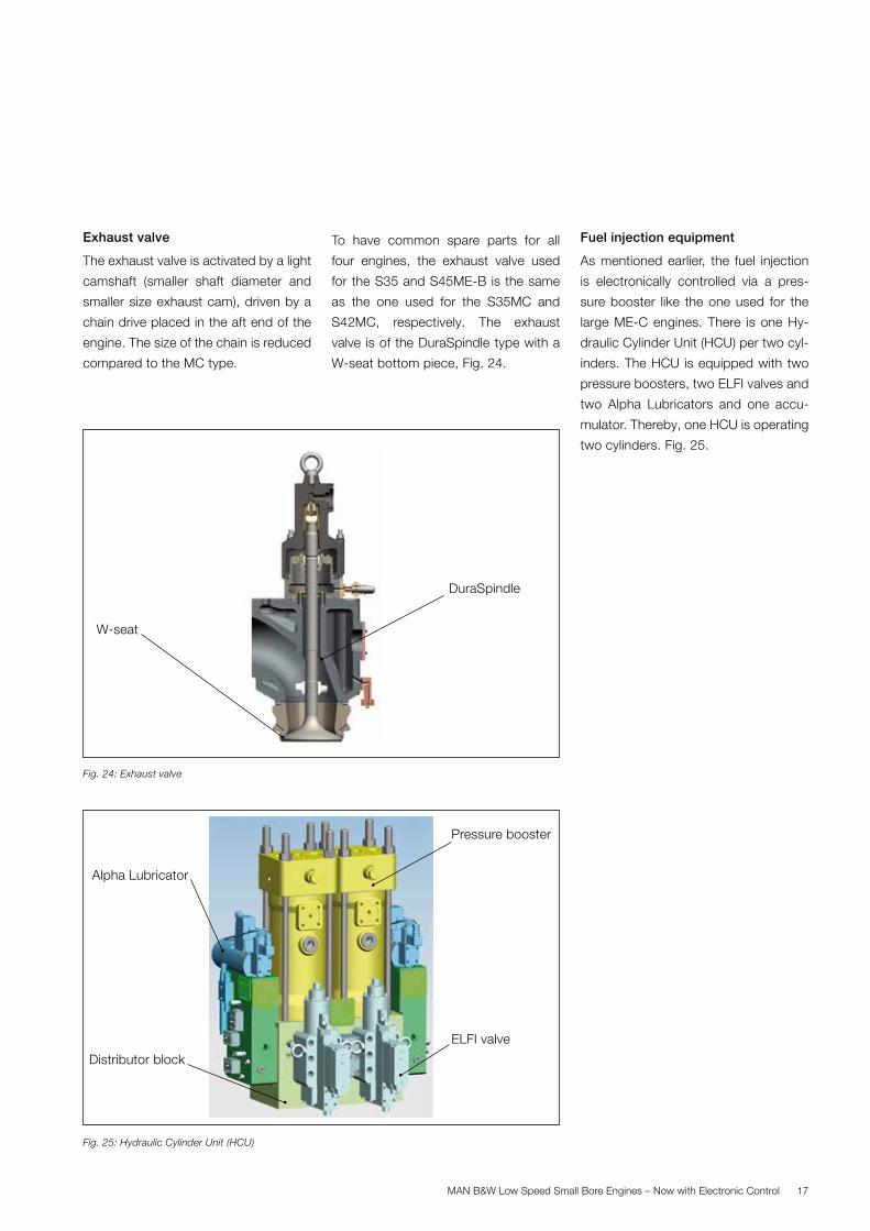
Exhaust valve
The exhaust valve is activated by a light
camshaft (smaller shaft diameter and
smaller size exhaust cam), driven by a
chain drive placed in the aft end of the
engine. The size of the chain is reduced
compared to the MC type.
To have common spare parts for all
four engines, the exhaust valve used
for the S35 and S45ME-B is the same
as the one used for the S35MC and
S42MC, respectively. The exhaust
valve is of the DuraSpindle type with a
W-seat bottom piece, Fig. 24.
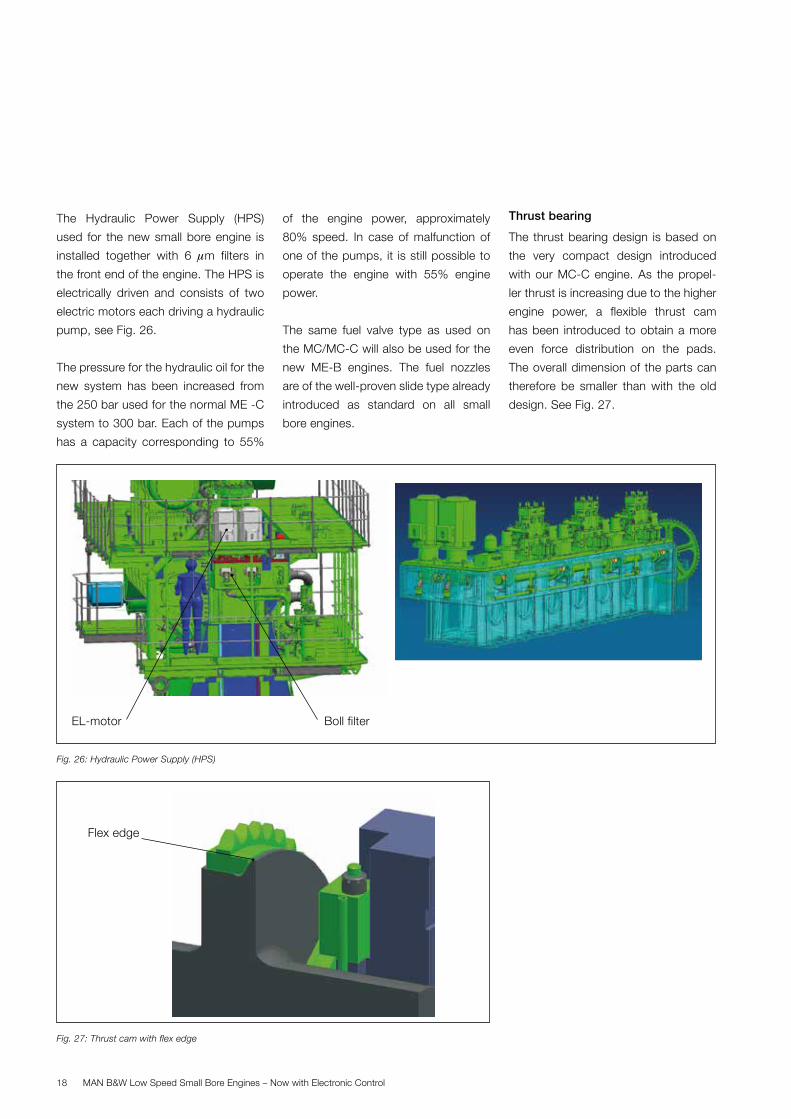
Fuel injection equipment
As mentioned earlier, the fuel injection
is electronically controlled via a pres-
sure booster like the one used for the
large ME-C engines. There is one Hy-
draulic Cylinder Unit (HCU) per two cyl-
inders. The HCU is equipped with two
pressure boosters, two ELFI valves and
two Alpha Lubricators and one accu-
mulator. Thereby, one HCU is operating
two cylinders. Fig. 25.
Fig. 24: Exhaust valve
Fig. 25: Hydraulic Cylinder Unit (HCU)
DuraSpindle
W-seat
Pressure booster
Alpha Lubricator
Distributor block
ELFI valve
MAN B&W Low Speed Small Bore Engines – Now with Electronic Control18
The Hydraulic Power Supply (HPS)
used for the new small bore engine is
installed together with 6 mm filters in
the front end of the engine. The HPS is
electrically driven and consists of two
electric motors each driving a hydraulic
pump, see Fig. 26.
The pressure for the hydraulic oil for the
new system has been increased from
the 250 bar used for the normal ME -C
system to 300 bar. Each of the pumps
has a capacity corresponding to 55%
of the engine power, approximately
80% speed. In case of malfunction of
one of the pumps, it is still possible to
operate the engine with 55% engine
power.
The same fuel valve type as used on
the MC/MC-C will also be used for the
new ME-B engines. The fuel nozzles
are of the well-proven slide type already
introduced as standard on all small
bore engines.
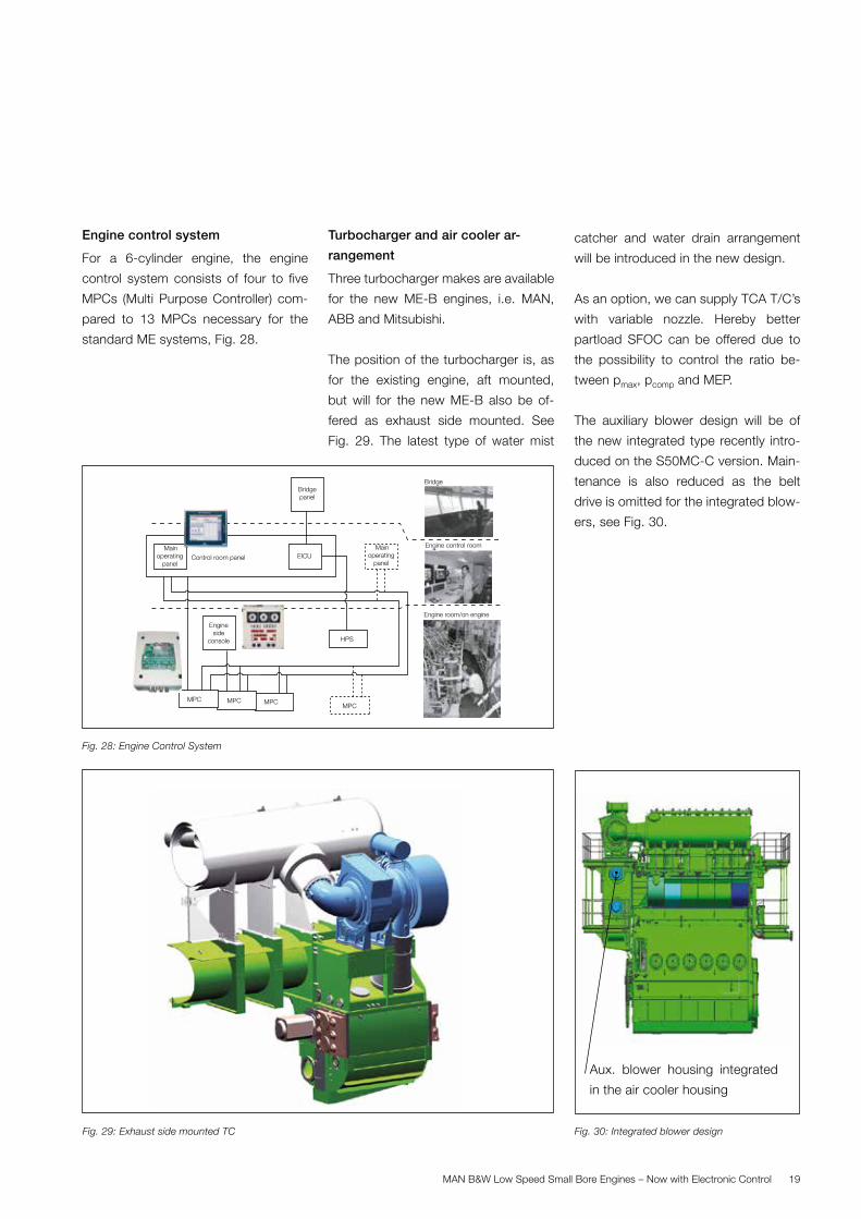
Thrust bearing
The thrust bearing design is based on
the very compact design introduced
with our MC-C engine. As the propel-
ler thrust is increasing due to the higher
engine power, a flexible thrust cam
has been introduced to obtain a more
even force distribution on the pads.
The overall dimension of the parts can
therefore be smaller than with the old
design. See Fig. 27.
Fig. 26: Hydraulic Power Supply (HPS)
Fig. 27: Thrust cam with flex edge
Flex edge
Boll filterEL-motor
MAN B&W Low Speed Small Bore Engines – Now with Electronic Control 19
Engine control system
For a 6-cylinder engine, the engine
control system consists of four to five
MPCs (Multi Purpose Controller) com-
pared to 13 MPCs necessary for the
standard ME systems, Fig. 28.
Turbocharger and air cooler ar-
rangement
Three turbocharger makes are available
for the new ME-B engines, i.e. MAN,
ABB and Mitsubishi.
The position of the turbocharger is, as
for the existing engine, aft mounted,
but will for the new ME-B also be of-
fered as exhaust side mounted. See
Fig. 29. The latest type of water mist
catcher and water drain arrangement
will be introduced in the new design.
As an option, we can supply TCA T/C’s
with variable nozzle. Hereby better
partload SFOC can be offered due to
the possibility to control the ratio be-
tween pmax, pcomp and MEP.
The auxiliary blower design will be of
the new integrated type recently intro-
duced on the S50MC-C version. Main-
tenance is also reduced as the belt
drive is omitted for the integrated blow-
ers, see Fig. 30.
Fig. 28: Engine Control System
Bridgepanel
Control room panel
Mainoperating
panel
Mainoperating
panel
EICU
Engineside
console
MPCMPC MPC
HPS
MPC
Bridge
Engine room/on engine
Engine control room
Fig. 30: Integrated blower design Fig. 29: Exhaust side mounted TC
Aux. blower housing integrated
in the air cooler housing
MAN B&W Low Speed Small Bore Engines – Now with Electronic Control20
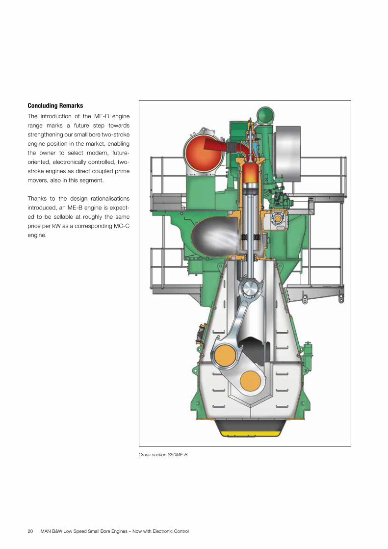
Concluding Remarks
The introduction of the ME-B engine
range marks a future step towards
strengthening our small bore two-stroke
engine position in the market, enabling
the owner to select modern, future-
oriented, electronically controlled, two-
stroke engines as direct coupled prime
movers, also in this segment.
Thanks to the design rationalisations
introduced, an ME-B engine is expect-
ed to be sellable at roughly the same
price per kW as a corresponding MC-C
engine.
Cross section S50ME-B


MAN Diesel & TurboTeglholmsgade 412450 Copenhagen SV, DenmarkPhone +45 33 85 11 00Fax +45 33 85 10 [email protected]
MAN Diesel & Turbo – a member of the MAN Group
All data provided in this document is non-binding. This data serves informational purposes only and is especially not guaranteed in any way. Depending on the subsequent specific individual projects, the relevant data may be subject to changes and will be assessed and determined individually for each project. This will depend on the particular characteristics of each individual project, especially specific site and operational conditions. Copyright © MAN Diesel & Turbo. 5510-0025-04ppr Sep 2014 Printed in Denmark
Recommended