Edition du :Issue Dated : 02/02/2016
MMEL . ./ EDIT .
LMER . DATERN0 09-44
RN1 10-27
RN2 10-51
RN3 11-20
RN4 12-06
RN5 14-01 R
LMER/MMEL AS 350/EC130SITUATION DES REVISIONS
REVISIONS STATUSEASA CERTIFICATION
Ce manuel doit contenir la révision normale (RN) référencée dans l'édition (EDIT) considérée.
This manual must contain the normal revision (RN) listed under the relevant issue (EDIT).
MMEL
LMER

AS 350 - EC 130 UPDATE GUIDE
JANUARY 2016 Page 1 / 3
REVISION TO AIRCRAFT PUBLICATION : AS 350 - EC 130
PUBLICATION CONCERNED : MMEL
CUSTOMIZATION AIRCRAFT S/N :
Part REVISION No.: 5 DATE CODE: 14-01 CERTIFICATION CODE: A
- The outline of the revision is given below : . Sections or supplements affected (added or modified), . Major points of the revision.
- Check that pages in each section are those specified in the list of effective pages.
- Withdraw old and insert new pages affected by this revision.
- Return the acknowledgement card.
- This list of amended pages may be filed (apart from the manual).
DELETED PAGES INSERTED PAGES
Section, SUP or
APP Pages Revision
Section, SUP or
APP Pages Revision
Normal Revision
00.00.00.P1 1 12-06 00.00.00.P1 1 14-01
00.00.00.P2 1 14-01
00.00.00.P5 1 to 3 12-06 00.00.00.P5 1 to 4 14-01
00.00.00.P6 1 12-06 00.00.00.P6 1 14-01
00.10.00 1 to 5 12-06 00.10.00 1 to 7 14-01
18.00.00 1 to 2 12-06 18.00.00 1 to 2 14-01
21.00.00 1 to 3 12-06 21.00.00 1 to 4 14-01
22.00.00 1 12-06 22.00.00 1 14-01
23.00.00 1 12-06 23.00.00 1 14-01
24.00.00 1 12-06 24.00.00 1 14-01
25.00.00 1 to 2 12-06 25.00.00 1 to 2 14-01
26.00.00 1 12-06 26.00.00 1 14-01
28.00.00 1 12-06 28.00.00 1 14-01
30.00.00 1 12-06 30.00.00 1 14-01
31.00.00 1 12-06 31.00.00 1 14-01
33.00.00 1 to 2 12-06 33.00.00 1 to 2 14-01
34.00.00 1 to 4 12-06 34.00.00 1 to 3 14-01
35.00.00 1 12-06 35.00.00 1 14-01
AS 350 - EC 130 UPDATE GUIDE
JANUARY 2016 Page 2 / 3
DELETED PAGES INSERTED PAGES
Section, SUP or
APP Pages Revision
Section, SUP or
APP Pages Revision
Normal Revision
52.00.00 1 12-06 52.00.00 1 14-01
62.00.00 1 12-06 62.00.00 1 14-01
63.00.00 1 12-06 63.00.00 1 14-01
65.00.00 1 12-06 65.00.00 1 14-01
71.00.00 1 12-06 71.00.00 1 14-01
72.00.00 1 12-06 72.00.00 1 14-01
77.00.00 1 12-06 77.00.00 1 14-01
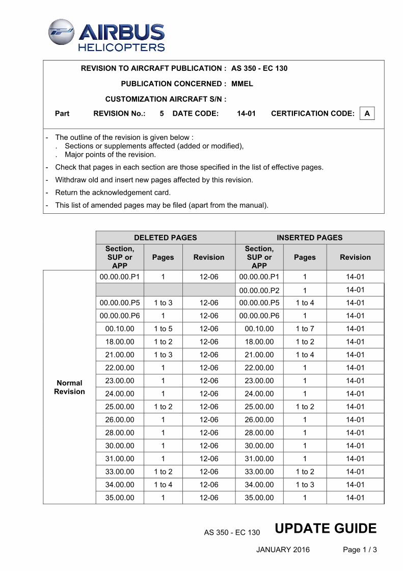
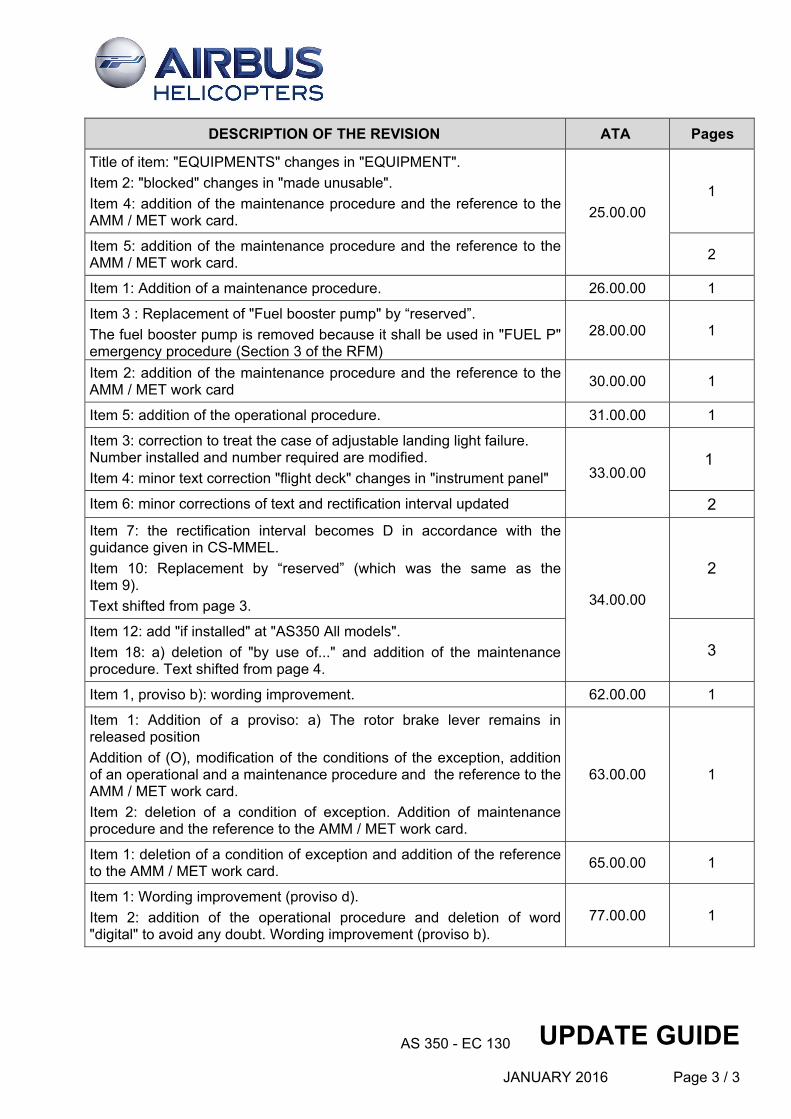
DESCRIPTION OF THE REVISION ATA Pages
MMEL EASA NR 5 issue 2 (Date code 14-01)
Replacement "EASA ACCEPTED" by "APPROVED" in the footer. All
First page in accordance with the JAA-MMEL Procedures manual. 00.00.00.P1 1
New page: list of approved MMEL supplements. 00.00.00.P2 1
Up-date of the list of effective pages. 00.00.00.P5 1
Updated for the new table of LOG OF REVISIONS and history of changes.
00.00.00.P5 2
ATA 25.00.00: "EQUIPMENT" instead of "EQUIPMENTS". 00.00.00.P6 1
Harmonisation and wording improvement. 00.10.00 1 to 7
All items "as required by the operational regulation" have now a repair interval in accordance with the guidance given in CS-MMEL.
Minor text correction for title of column (1) ("SYSTEM" changes in "SYSTEMS")
Addition of "if installed" for optional equipment items.
All All
Item 2 and 3: addition of the operational procedure. Item 4 and 5: addition of the maintenance procedure. Item 7: addition of "backup" for the P2 valve. 21.00.00
1
New page. Item 8 shifted from page 3 to page 4.
4
Item 8: Replacement of "Cockpit Voice Recorder" by “reserved”. The Cockpit Voice Recorder is not installed on AS350 / EC130.
23.00.00 1
Item 1: "system" changes in "light".
Item 2: modification of the conditions of the exception, addition of the maintenance procedure and the reference to the AMM / MET work card.
Item 5: addition of the maintenance procedure and the reference to the AMM / MET work card.
24.00.00 1
AS 350 - EC 130 UPDATE GUIDE
JANUARY 2016 Page 3 / 3
DESCRIPTION OF THE REVISION ATA Pages
Title of item: "EQUIPMENTS" changes in "EQUIPMENT".
Item 2: "blocked" changes in "made unusable".
Item 4: addition of the maintenance procedure and the reference to the AMM / MET work card. 25.00.00
1
Item 5: addition of the maintenance procedure and the reference to the AMM / MET work card.
2
Item 1: Addition of a maintenance procedure. 26.00.00 1
Item 3 : Replacement of "Fuel booster pump" by “reserved”.
The fuel booster pump is removed because it shall be used in "FUEL P" emergency procedure (Section 3 of the RFM)
28.00.00 1
Item 2: addition of the maintenance procedure and the reference to the AMM / MET work card
30.00.00 1
Item 5: addition of the operational procedure. 31.00.00 1
Item 3: correction to treat the case of adjustable landing light failure. Number installed and number required are modified.
Item 4: minor text correction "flight deck" changes in "instrument panel" 33.00.00 1
Item 6: minor corrections of text and rectification interval updated 2
Item 7: the rectification interval becomes D in accordance with the guidance given in CS-MMEL.
Item 10: Replacement by “reserved” (which was the same as the Item 9).
Text shifted from page 3. 34.00.00
2
Item 12: add "if installed" at "AS350 All models".
Item 18: a) deletion of "by use of..." and addition of the maintenance procedure. Text shifted from page 4.
3
Item 1, proviso b): wording improvement. 62.00.00 1
Item 1: Addition of a proviso: a) The rotor brake lever remains in released position
Addition of (O), modification of the conditions of the exception, addition of an operational and a maintenance procedure and the reference to the AMM / MET work card.
Item 2: deletion of a condition of exception. Addition of maintenance procedure and the reference to the AMM / MET work card.
63.00.00 1
Item 1: deletion of a condition of exception and addition of the reference to the AMM / MET work card.
65.00.00 1
Item 1: Wording improvement (proviso d).
Item 2: addition of the operational procedure and deletion of word "digital" to avoid any doubt. Wording improvement (proviso b).
77.00.00 1

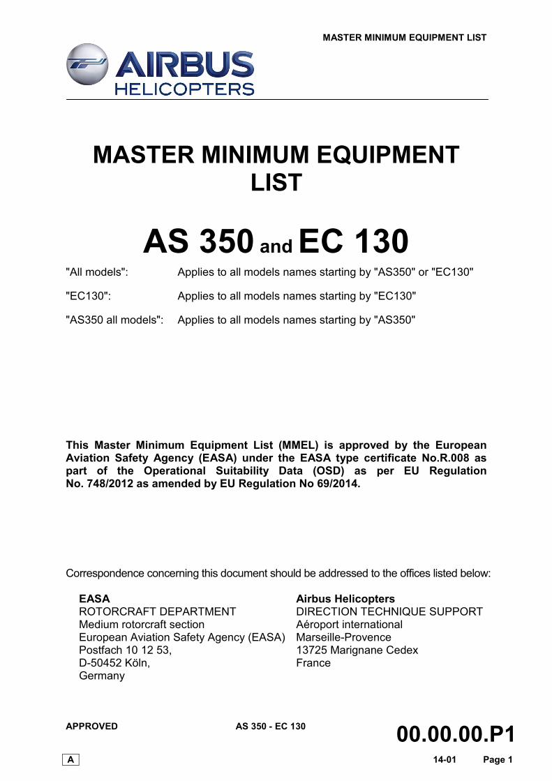
MASTER MINIMUM EQUIPMENT LIST
APPROVED AS 350 - EC 130 00.00.00.P1 A 14-01 Page 1
MASTER MINIMUM EQUIPMENT LIST
AS 350 and EC 130
"All models": Applies to all models names starting by "AS350" or "EC130"
"EC130": Applies to all models names starting by "EC130"
"AS350 all models": Applies to all models names starting by "AS350"
This Master Minimum Equipment List (MMEL) is approved by the European Aviation Safety Agency (EASA) under the EASA type certificate No.R.008 as part of the Operational Suitability Data (OSD) as per EU Regulation No. 748/2012 as amended by EU Regulation No 69/2014. Correspondence concerning this document should be addressed to the offices listed below:
EASA Airbus Helicopters ROTORCRAFT DEPARTMENT DIRECTION TECHNIQUE SUPPORT Medium rotorcraft section Aéroport international European Aviation Safety Agency (EASA) Marseille-Provence Postfach 10 12 53, 13725 Marignane Cedex D-50452 Köln, France Germany

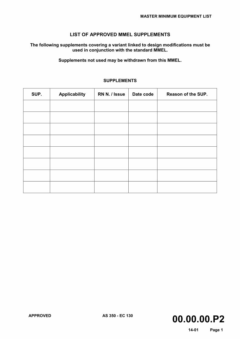
MASTER MINIMUM EQUIPMENT LIST
APPROVED AS 350 - EC 130 00.00.00.P2 14-01 Page 1
LIST OF APPROVED MMEL SUPPLEMENTS
The following supplements covering a variant linked to design modifications must be
used in conjunction with the standard MMEL.
Supplements not used may be withdrawn from this MMEL.
SUPPLEMENTS
SUP. Applicability RN N. / Issue Date code Reason of the SUP.

MASTER MINIMUM EQUIPMENT LIST
APPROVED AS 350 - EC 130 00.00.00.P5 A 14-01 Page 1
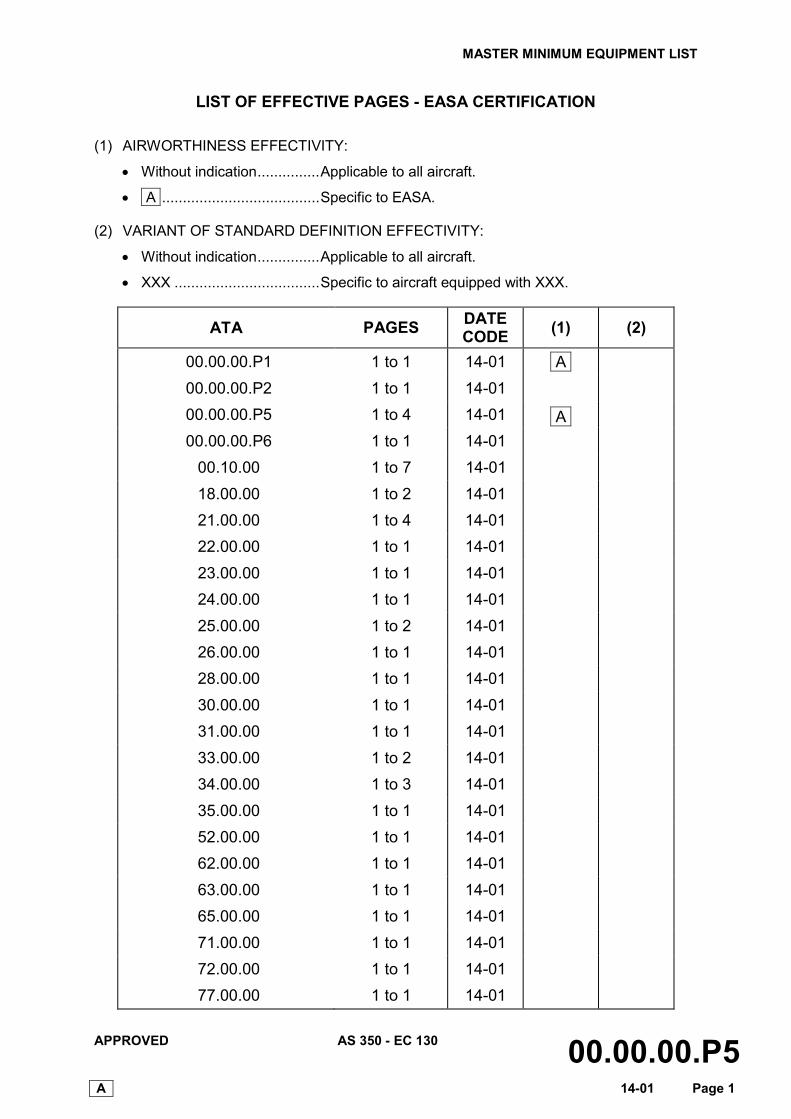
LIST OF EFFECTIVE PAGES - EASA CERTIFICATION
(1) AIRWORTHINESS EFFECTIVITY:
• Without indication ............... Applicable to all aircraft.
• A ...................................... Specific to EASA.
(2) VARIANT OF STANDARD DEFINITION EFFECTIVITY:
• Without indication ............... Applicable to all aircraft.
• XXX ................................... Specific to aircraft equipped with XXX.
ATA PAGES DATE CODE (1) (2)
00.00.00.P1 1 to 1 14-01 A
00.00.00.P2 1 to 1 14-01
00.00.00.P5 1 to 4 14-01 A
00.00.00.P6 1 to 1 14-01
00.10.00 1 to 7 14-01
18.00.00 1 to 2 14-01
21.00.00 1 to 4 14-01
22.00.00 1 to 1 14-01
23.00.00 1 to 1 14-01
24.00.00 1 to 1 14-01
25.00.00 1 to 2 14-01
26.00.00 1 to 1 14-01
28.00.00 1 to 1 14-01
30.00.00 1 to 1 14-01
31.00.00 1 to 1 14-01
33.00.00 1 to 2 14-01
34.00.00 1 to 3 14-01
35.00.00 1 to 1 14-01
52.00.00 1 to 1 14-01
62.00.00 1 to 1 14-01
63.00.00 1 to 1 14-01
65.00.00 1 to 1 14-01
71.00.00 1 to 1 14-01
72.00.00 1 to 1 14-01
77.00.00 1 to 1 14-01
MASTER MINIMUM EQUIPMENT LIST
APPROVED AS 350 - EC 130 00.00.00.P5 A 14-01 Page 2
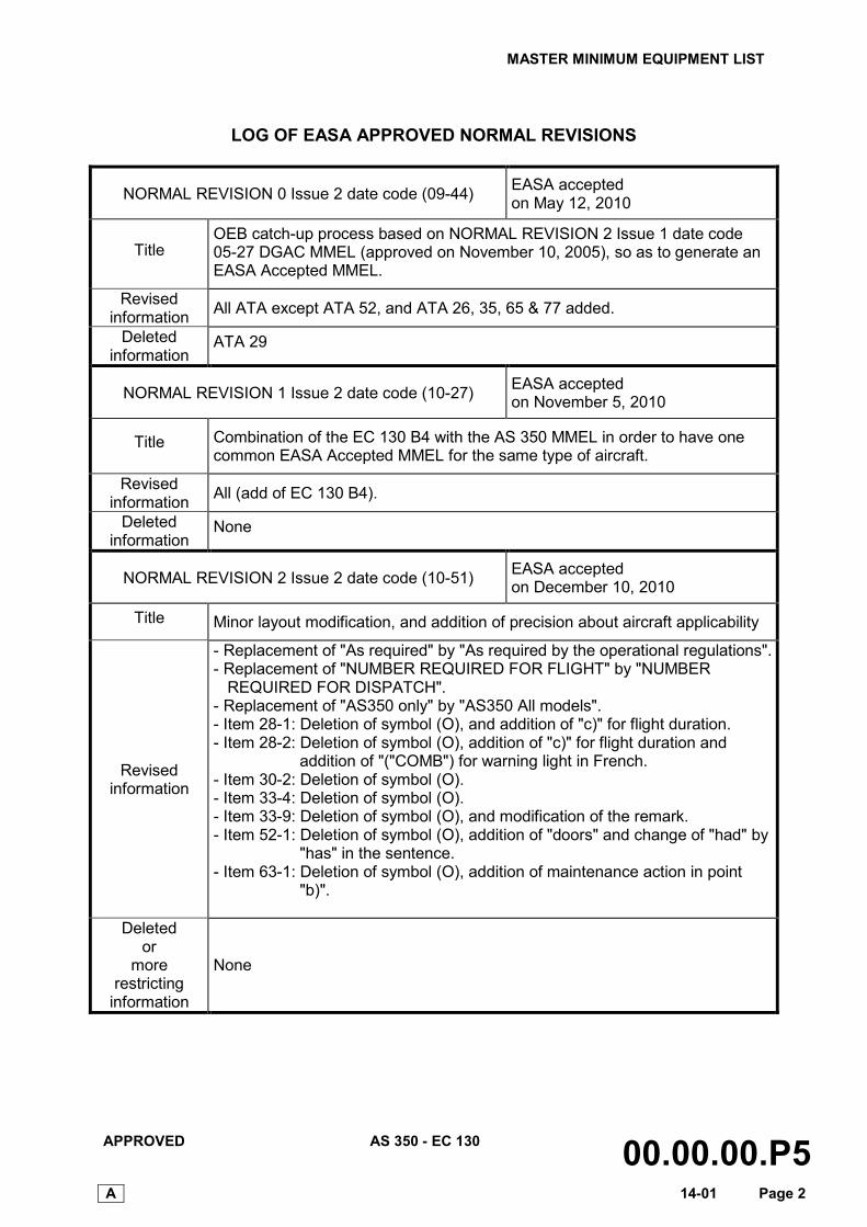
LOG OF EASA APPROVED NORMAL REVISIONS
NORMAL REVISION 0 Issue 2 date code (09-44) EASA accepted on May 12, 2010
Title OEB catch-up process based on NORMAL REVISION 2 Issue 1 date code 05-27 DGAC MMEL (approved on November 10, 2005), so as to generate an EASA Accepted MMEL.
Revised information All ATA except ATA 52, and ATA 26, 35, 65 & 77 added.
Deleted information
ATA 29
NORMAL REVISION 1 Issue 2 date code (10-27) EASA accepted on November 5, 2010
Title Combination of the EC 130 B4 with the AS 350 MMEL in order to have one common EASA Accepted MMEL for the same type of aircraft.
Revised information All (add of EC 130 B4).
Deleted information
None
NORMAL REVISION 2 Issue 2 date code (10-51) EASA accepted on December 10, 2010
Title Minor layout modification, and addition of precision about aircraft applicability
Revised information
- Replacement of "As required" by "As required by the operational regulations". - Replacement of "NUMBER REQUIRED FOR FLIGHT" by "NUMBER
REQUIRED FOR DISPATCH". - Replacement of "AS350 only" by "AS350 All models". - Item 28-1: Deletion of symbol (O), and addition of "c)" for flight duration. - Item 28-2: Deletion of symbol (O), addition of "c)" for flight duration and
addition of "("COMB") for warning light in French. - Item 30-2: Deletion of symbol (O). - Item 33-4: Deletion of symbol (O). - Item 33-9: Deletion of symbol (O), and modification of the remark. - Item 52-1: Deletion of symbol (O), addition of "doors" and change of "had" by
"has" in the sentence. - Item 63-1: Deletion of symbol (O), addition of maintenance action in point
"b)".
Deleted or
more restricting
information
None
MASTER MINIMUM EQUIPMENT LIST
APPROVED AS 350 - EC 130 00.00.00.P5 A 14-01 Page 3
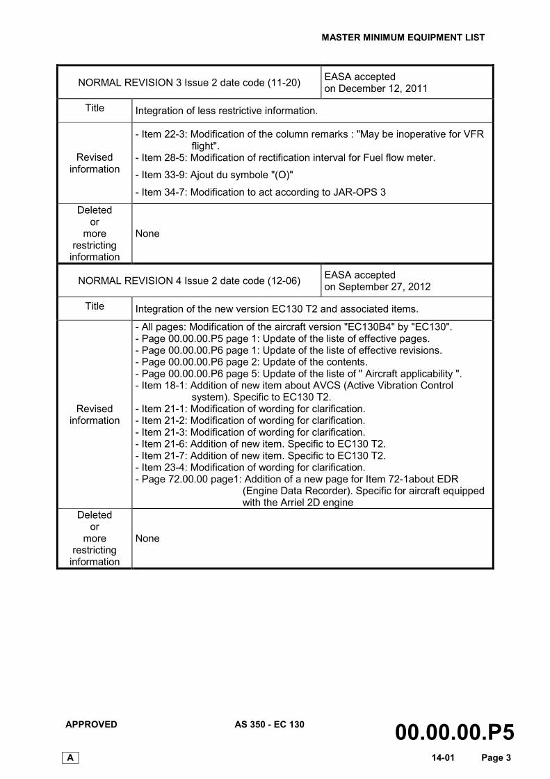
NORMAL REVISION 3 Issue 2 date code (11-20) EASA accepted on December 12, 2011
Title Integration of less restrictive information.
Revised information
- Item 22-3: Modification of the column remarks : "May be inoperative for VFR flight".
- Item 28-5: Modification of rectification interval for Fuel flow meter.
- Item 33-9: Ajout du symbole "(O)"
- Item 34-7: Modification to act according to JAR-OPS 3
Deleted or
more restricting
information
None
NORMAL REVISION 4 Issue 2 date code (12-06) EASA accepted on September 27, 2012
Title Integration of the new version EC130 T2 and associated items.
Revised information
- All pages: Modification of the aircraft version "EC130B4" by "EC130". - Page 00.00.00.P5 page 1: Update of the liste of effective pages. - Page 00.00.00.P6 page 1: Update of the liste of effective revisions. - Page 00.00.00.P6 page 2: Update of the contents. - Page 00.00.00.P6 page 5: Update of the liste of " Aircraft applicability ". - Item 18-1: Addition of new item about AVCS (Active Vibration Control
system). Specific to EC130 T2. - Item 21-1: Modification of wording for clarification. - Item 21-2: Modification of wording for clarification. - Item 21-3: Modification of wording for clarification. - Item 21-6: Addition of new item. Specific to EC130 T2. - Item 21-7: Addition of new item. Specific to EC130 T2. - Item 23-4: Modification of wording for clarification. - Page 72.00.00 page1: Addition of a new page for Item 72-1about EDR
(Engine Data Recorder). Specific for aircraft equipped with the Arriel 2D engine
Deleted or
more restricting
information
None
MASTER MINIMUM EQUIPEMENTLIST
APPROVED AS 350 - EC 130 00.00.00.P5A 14-01 Page 4
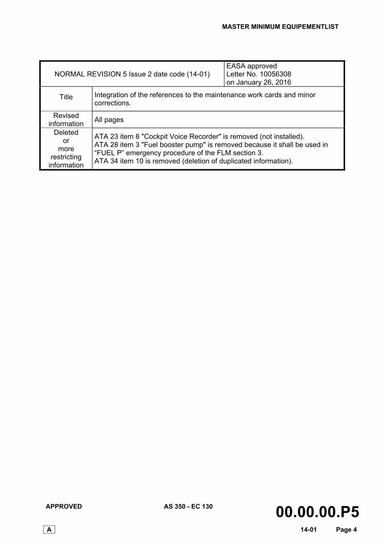
NORMAL REVISION 5 Issue 2 date code (14-01) EASA approved Letter No. 10056308 on January 26, 2016
Title Integration of the references to the maintenance work cards and minor corrections.
Revised information
All pages
Deleted or
more restricting
information
ATA 23 item 8 "Cockpit Voice Recorder" is removed (not installed). ATA 28 item 3 "Fuel booster pump" is removed because it shall be used in “FUEL P” emergency procedure of the FLM section 3. ATA 34 item 10 is removed (deletion of duplicated information).
MASTER MINIMUM EQUIPMENT LIST
APPROVED AS 350 - EC 130 00.00.00.P6 14-01 Page 1
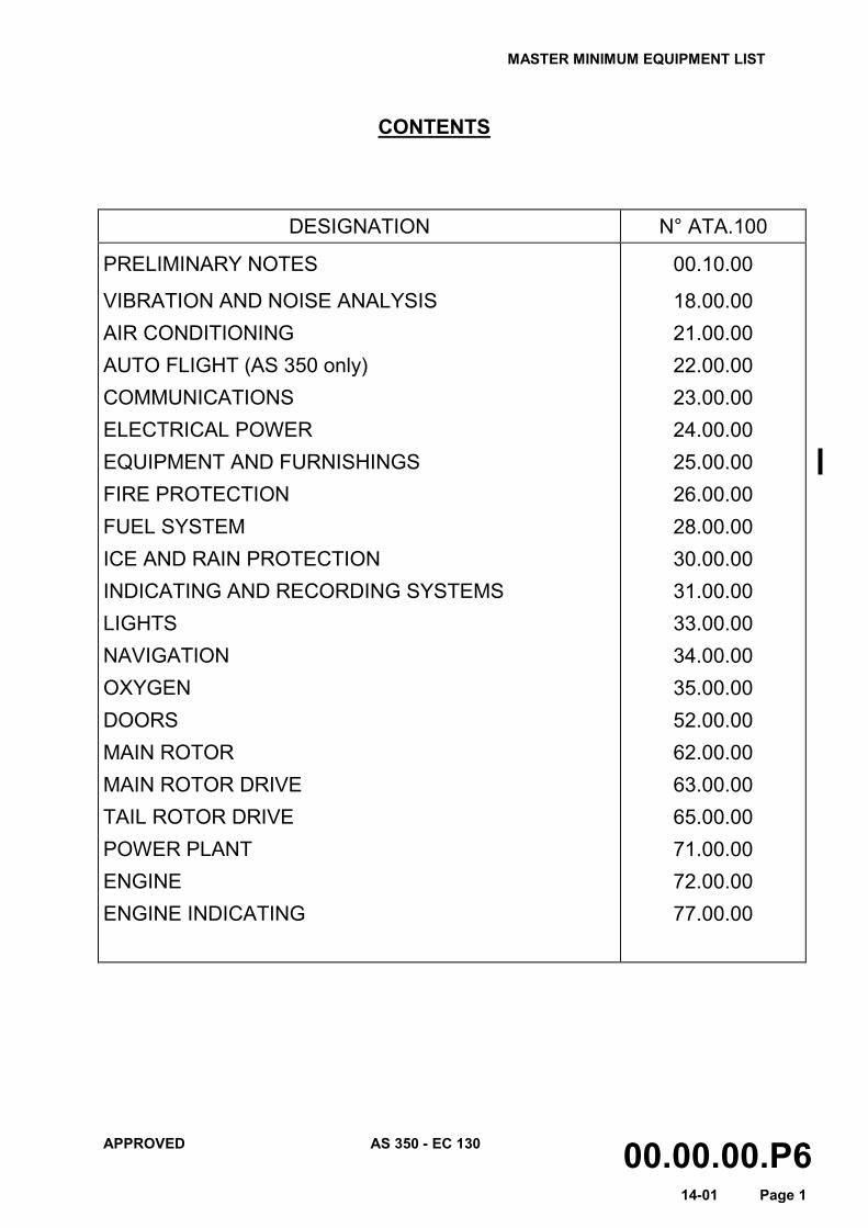
CONTENTS
DESIGNATION N° ATA.100
PRELIMINARY NOTES
VIBRATION AND NOISE ANALYSIS AIR CONDITIONING AUTO FLIGHT (AS 350 only) COMMUNICATIONS ELECTRICAL POWER EQUIPMENT AND FURNISHINGS FIRE PROTECTION FUEL SYSTEM ICE AND RAIN PROTECTION INDICATING AND RECORDING SYSTEMS LIGHTS NAVIGATION OXYGEN DOORS MAIN ROTOR MAIN ROTOR DRIVE TAIL ROTOR DRIVE POWER PLANT ENGINE ENGINE INDICATING
00.10.00
18.00.00 21.00.00 22.00.00 23.00.00 24.00.00 25.00.00 26.00.00 28.00.00 30.00.00 31.00.00 33.00.00 34.00.00 35.00.00 52.00.00 62.00.00 63.00.00 65.00.00 71.00.00 72.00.00 77.00.00

MASTER MINIMUM EQUIPMENT LIST
APPROVED AS 350 - EC 130 00.10.00 14-01 Page 1
PRELIMINARY NOTES
1 PREAMBLE
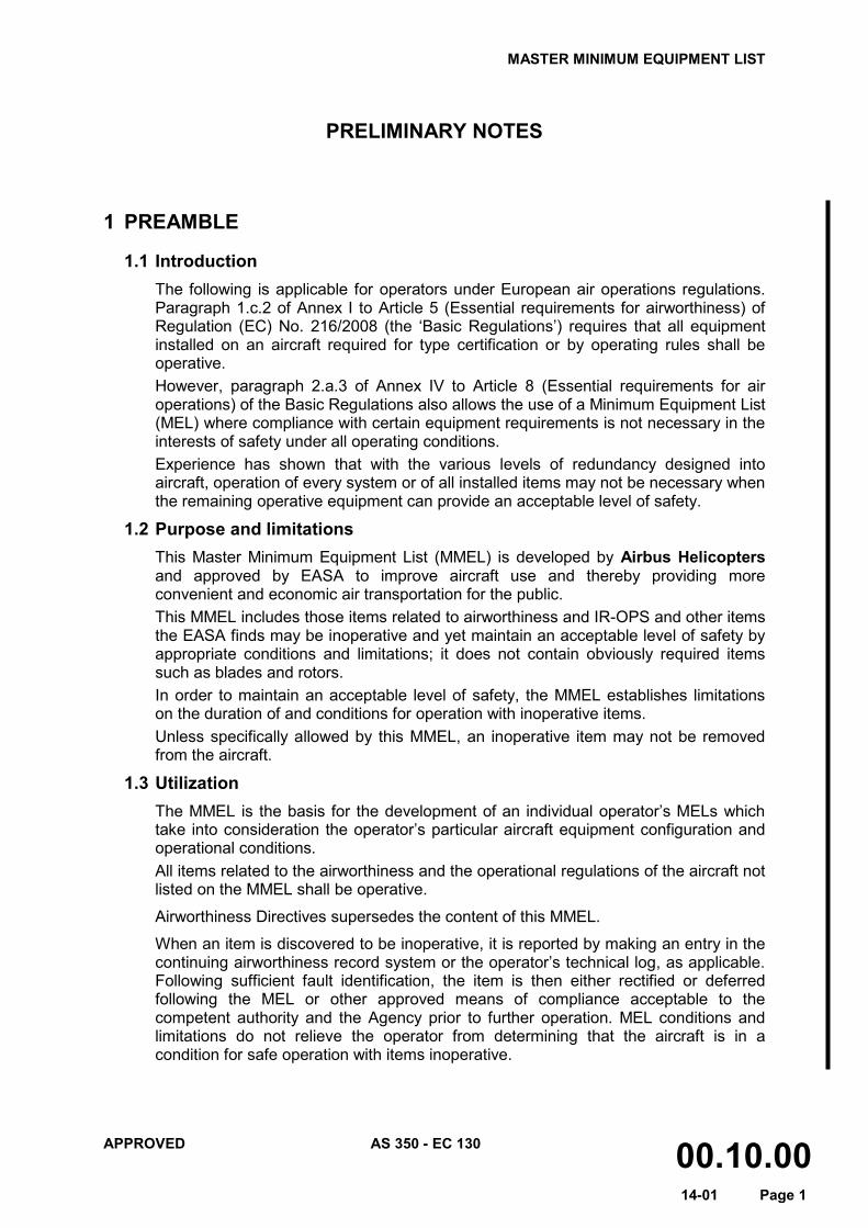
1.1 Introduction The following is applicable for operators under European air operations regulations. Paragraph 1.c.2 of Annex I to Article 5 (Essential requirements for airworthiness) of Regulation (EC) No. 216/2008 (the ‘Basic Regulations’) requires that all equipment installed on an aircraft required for type certification or by operating rules shall be operative. However, paragraph 2.a.3 of Annex IV to Article 8 (Essential requirements for air operations) of the Basic Regulations also allows the use of a Minimum Equipment List (MEL) where compliance with certain equipment requirements is not necessary in the interests of safety under all operating conditions. Experience has shown that with the various levels of redundancy designed into aircraft, operation of every system or of all installed items may not be necessary when the remaining operative equipment can provide an acceptable level of safety.
1.2 Purpose and limitations This Master Minimum Equipment List (MMEL) is developed by Airbus Helicopters and approved by EASA to improve aircraft use and thereby providing more convenient and economic air transportation for the public. This MMEL includes those items related to airworthiness and IR-OPS and other items the EASA finds may be inoperative and yet maintain an acceptable level of safety by appropriate conditions and limitations; it does not contain obviously required items such as blades and rotors. In order to maintain an acceptable level of safety, the MMEL establishes limitations on the duration of and conditions for operation with inoperative items. Unless specifically allowed by this MMEL, an inoperative item may not be removed from the aircraft.
1.3 Utilization The MMEL is the basis for the development of an individual operator’s MELs which take into consideration the operator’s particular aircraft equipment configuration and operational conditions. All items related to the airworthiness and the operational regulations of the aircraft not listed on the MMEL shall be operative.
Airworthiness Directives supersedes the content of this MMEL.
When an item is discovered to be inoperative, it is reported by making an entry in the continuing airworthiness record system or the operator’s technical log, as applicable. Following sufficient fault identification, the item is then either rectified or deferred following the MEL or other approved means of compliance acceptable to the competent authority and the Agency prior to further operation. MEL conditions and limitations do not relieve the operator from determining that the aircraft is in a condition for safe operation with items inoperative.
MASTER MINIMUM EQUIPMENT LIST
APPROVED AS 350 - EC 130 00.10.00 14-01 Page 2
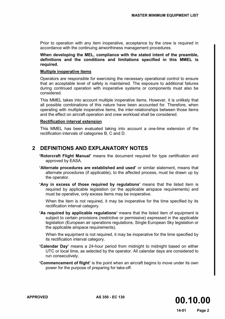
Prior to operation with any item inoperative, acceptance by the crew is required in accordance with the continuing airworthiness management procedures.
When developing the MEL, compliance with the stated intent of the preamble, definitions and the conditions and limitations specified in this MMEL is required. Multiple inoperative items Operators are responsible for exercising the necessary operational control to ensure that an acceptable level of safety is maintained. The exposure to additional failures during continued operation with inoperative systems or components must also be considered.
This MMEL takes into account multiple inoperative items. However, it is unlikely that all possible combinations of this nature have been accounted for. Therefore, when operating with multiple inoperative items, the inter-relationships between those items and the effect on aircraft operation and crew workload shall be considered.
Rectification interval extension This MMEL has been evaluated taking into account a one-time extension of the rectification intervals of categories B, C and D.
2 DEFINITIONS AND EXPLANATORY NOTES ‘Rotorcraft Flight Manual’ means the document required for type certification and
approved by EASA.
‘Alternate procedures are established and used’ or similar statement, means that alternate procedures (if applicable), to the affected process, must be drawn up by the operator.
‘Any in excess of those required by regulations’ means that the listed item is required by applicable legislation (or the applicable airspace requirements) and must be operative, only excess items may be inoperative.
When the item is not required, it may be inoperative for the time specified by its rectification interval category.
‘As required by applicable regulations‘ means that the listed item of equipment is subject to certain provisions (restrictive or permissive) expressed in the applicable legislation (European air operations regulations, Single European Sky legislation or the applicable airspace requirements).
When the equipment is not required, it may be inoperative for the time specified by its rectification interval category.
‘Calendar Day’ means a 24-hour period from midnight to midnight based on either UTC or local time, as selected by the operator. All calendar days are considered to run consecutively.
‘Commencement of flight’ is the point when an aircraft begins to move under its own power for the purpose of preparing for take-off.
MASTER MINIMUM EQUIPMENT LIST
APPROVED AS 350 - EC 130 00.10.00 14-01 Page 3
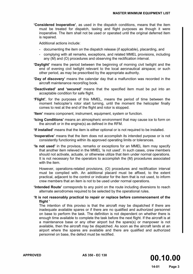
‘Considered Inoperative’, as used in the dispatch conditions, means that the item must be treated for dispatch, taxiing and flight purposes as though it were inoperative. The item shall not be used or operated until the original deferred item is repaired.
Additional actions include:
- documenting the item on the dispatch release (if applicable), placarding, and - complying with all remarks, exceptions, and related MMEL provisions, including
any (M) and (O) procedures and observing the rectification interval.
‘Daylight’ means the period between the beginning of morning civil twilight and the end of evening civil twilight relevant to the local aeronautical airspace; or such other period, as may be prescribed by the appropriate authority.
‘Day of discovery’ means the calendar day that a malfunction was recorded in the aircraft maintenance record/log book.
‘Deactivated’ and ‘secured’ means that the specified item must be put into an acceptable condition for safe flight.
‘Flight’, for the purposes of this MMEL, means the period of time between the moment helicopter’s rotor start turning, until the moment the helicopter finally comes to rest at the end of the flight and rotor is stopped.
‘Item’ means component, instrument, equipment, system or function.
‘Icing Conditions’ means an atmospheric environment that may cause ice to form on the aircraft or in the engine(s) as defined in the RFM.
‘If installed’ means that the item is either optional or is not required to be installed.
‘Inoperative’ means that the item does not accomplish its intended purpose or is not consistently functioning within its approved operating limits or tolerances.
‘Is not used’ in the provisos, remarks or exceptions for an MMEL item may specify that another item relieved in the MMEL ‘is not used’. In such cases, crew members should not activate, actuate, or otherwise utilize that item under normal operations. It is not necessary for the operators to accomplish the (M) procedures associated with the item.
However, operations-related provisions, (O) procedures and rectification interval must be complied with. An additional placard must be affixed, to the extent practical, adjacent to the control or indicator for the item that is not used, to inform crew members that an item is not to be used under normal operations.
‘Intended Route’ corresponds to any point on the route including diversions to reach alternate aerodromes required to be selected by the operational rules.
‘It is not reasonably practical to repair or replace before commencement of the flight ’ The intention of this proviso is that the aircraft may be dispatched if there are inadequate available spares or if there are no qualified and authorized personnel on base to perform the task. The definition is not dependent on whether there is enough time available to complete the task before the next flight. If the aircraft is at a maintenance base or any other airport but the spare(s) or manpower is not available, then the aircraft may be dispatched. As soon as the aircraft lands at an airport where the spares are available and there are qualified and authorized personnel on base, the defect must be rectified.
MASTER MINIMUM EQUIPMENT LIST
APPROVED AS 350 - EC 130 00.10.00 14-01 Page 4
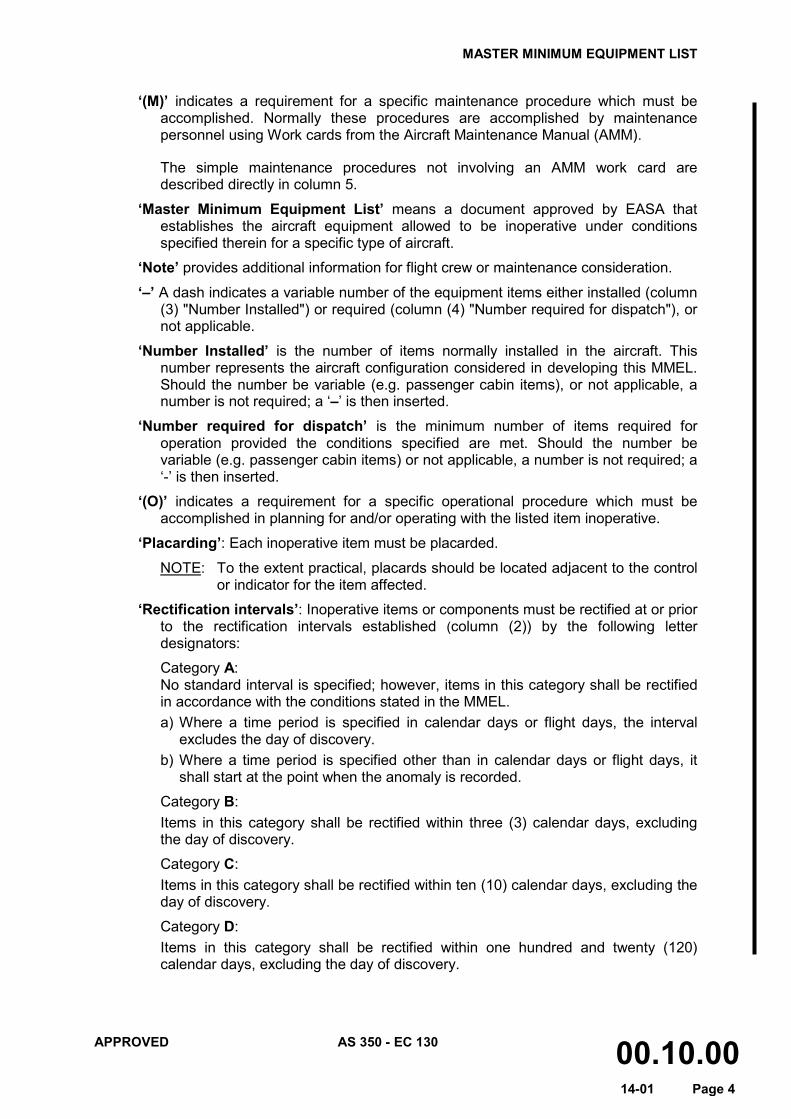
‘(M)’ indicates a requirement for a specific maintenance procedure which must be accomplished. Normally these procedures are accomplished by maintenance personnel using Work cards from the Aircraft Maintenance Manual (AMM).
The simple maintenance procedures not involving an AMM work card are described directly in column 5.
‘Master Minimum Equipment List’ means a document approved by EASA that establishes the aircraft equipment allowed to be inoperative under conditions specified therein for a specific type of aircraft.
‘Note’ provides additional information for flight crew or maintenance consideration.
‘–’ A dash indicates a variable number of the equipment items either installed (column (3) "Number Installed") or required (column (4) "Number required for dispatch"), or not applicable.
‘Number Installed’ is the number of items normally installed in the aircraft. This number represents the aircraft configuration considered in developing this MMEL. Should the number be variable (e.g. passenger cabin items), or not applicable, a number is not required; a ‘–’ is then inserted.
‘Number required for dispatch’ is the minimum number of items required for operation provided the conditions specified are met. Should the number be variable (e.g. passenger cabin items) or not applicable, a number is not required; a ‘-’ is then inserted.
‘(O)’ indicates a requirement for a specific operational procedure which must be accomplished in planning for and/or operating with the listed item inoperative.
‘Placarding’: Each inoperative item must be placarded.
NOTE: To the extent practical, placards should be located adjacent to the control or indicator for the item affected.
‘Rectification intervals’: Inoperative items or components must be rectified at or prior to the rectification intervals established (column (2)) by the following letter designators:
Category A: No standard interval is specified; however, items in this category shall be rectified in accordance with the conditions stated in the MMEL. a) Where a time period is specified in calendar days or flight days, the interval
excludes the day of discovery. b) Where a time period is specified other than in calendar days or flight days, it
shall start at the point when the anomaly is recorded.
Category B: Items in this category shall be rectified within three (3) calendar days, excluding the day of discovery.
Category C: Items in this category shall be rectified within ten (10) calendar days, excluding the day of discovery.
Category D: Items in this category shall be rectified within one hundred and twenty (120) calendar days, excluding the day of discovery.
MASTER MINIMUM EQUIPMENT LIST
APPROVED AS 350 - EC 130 00.10.00 14-01 Page 5
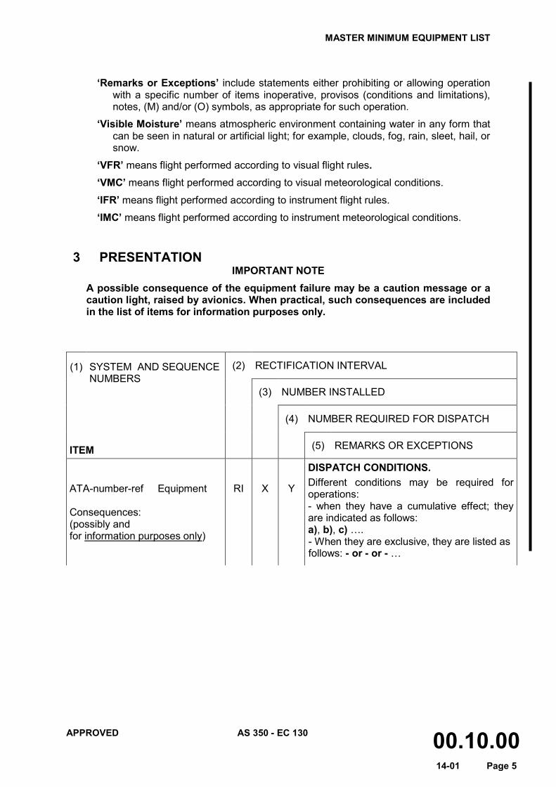
‘Remarks or Exceptions’ include statements either prohibiting or allowing operation
with a specific number of items inoperative, provisos (conditions and limitations), notes, (M) and/or (O) symbols, as appropriate for such operation.
‘Visible Moisture’ means atmospheric environment containing water in any form that can be seen in natural or artificial light; for example, clouds, fog, rain, sleet, hail, or snow.
‘VFR’ means flight performed according to visual flight rules. ‘VMC’ means flight performed according to visual meteorological conditions.
‘IFR’ means flight performed according to instrument flight rules.
‘IMC’ means flight performed according to instrument meteorological conditions.
3 PRESENTATION
IMPORTANT NOTE A possible consequence of the equipment failure may be a caution message or a caution light, raised by avionics. When practical, such consequences are included in the list of items for information purposes only.
(1)
SYSTEM AND SEQUENCE NUMBERS
(2) RECTIFICATION INTERVAL
(3) NUMBER INSTALLED
(4) NUMBER REQUIRED FOR DISPATCH
ITEM
(5) REMARKS OR EXCEPTIONS
ATA-number-ref Equipment Consequences: (possibly and for information purposes only)
RI
X
Y
DISPATCH CONDITIONS. Different conditions may be required for operations: - when they have a cumulative effect; they are indicated as follows: a), b), c) …. - When they are exclusive, they are listed as follows: - or - or - …
MASTER MINIMUM EQUIPMENT LIST
APPROVED AS 350 - EC 130 00.10.00 14-01 Page 6
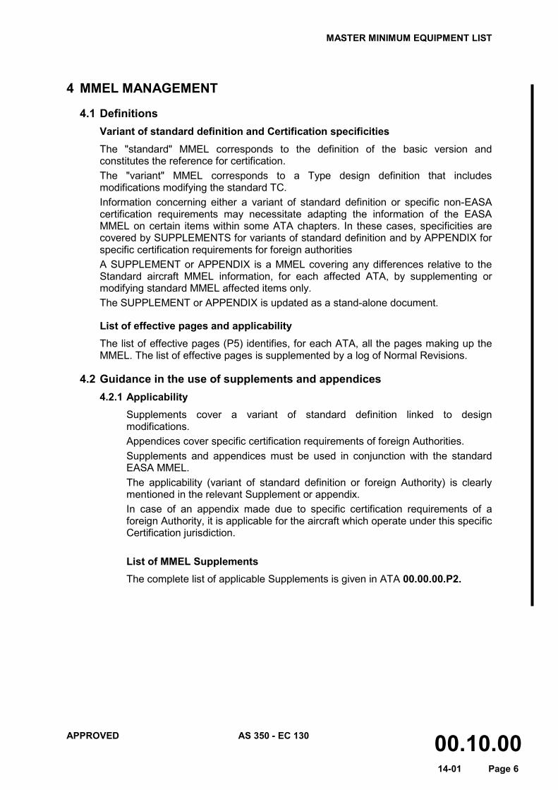
4 MMEL MANAGEMENT
4.1 Definitions Variant of standard definition and Certification specificities The "standard" MMEL corresponds to the definition of the basic version and constitutes the reference for certification. The "variant" MMEL corresponds to a Type design definition that includes modifications modifying the standard TC. Information concerning either a variant of standard definition or specific non-EASA certification requirements may necessitate adapting the information of the EASA MMEL on certain items within some ATA chapters. In these cases, specificities are covered by SUPPLEMENTS for variants of standard definition and by APPENDIX for specific certification requirements for foreign authorities A SUPPLEMENT or APPENDIX is a MMEL covering any differences relative to the Standard aircraft MMEL information, for each affected ATA, by supplementing or modifying standard MMEL affected items only. The SUPPLEMENT or APPENDIX is updated as a stand-alone document.
List of effective pages and applicability The list of effective pages (P5) identifies, for each ATA, all the pages making up the MMEL. The list of effective pages is supplemented by a log of Normal Revisions.
4.2 Guidance in the use of supplements and appendices 4.2.1 Applicability
Supplements cover a variant of standard definition linked to design modifications. Appendices cover specific certification requirements of foreign Authorities. Supplements and appendices must be used in conjunction with the standard EASA MMEL. The applicability (variant of standard definition or foreign Authority) is clearly mentioned in the relevant Supplement or appendix. In case of an appendix made due to specific certification requirements of a foreign Authority, it is applicable for the aircraft which operate under this specific Certification jurisdiction.
List of MMEL Supplements The complete list of applicable Supplements is given in ATA 00.00.00.P2.
MASTER MINIMUM EQUIPMENT LIST
APPROVED AS 350 - EC 130 00.10.00 14-01 Page 7
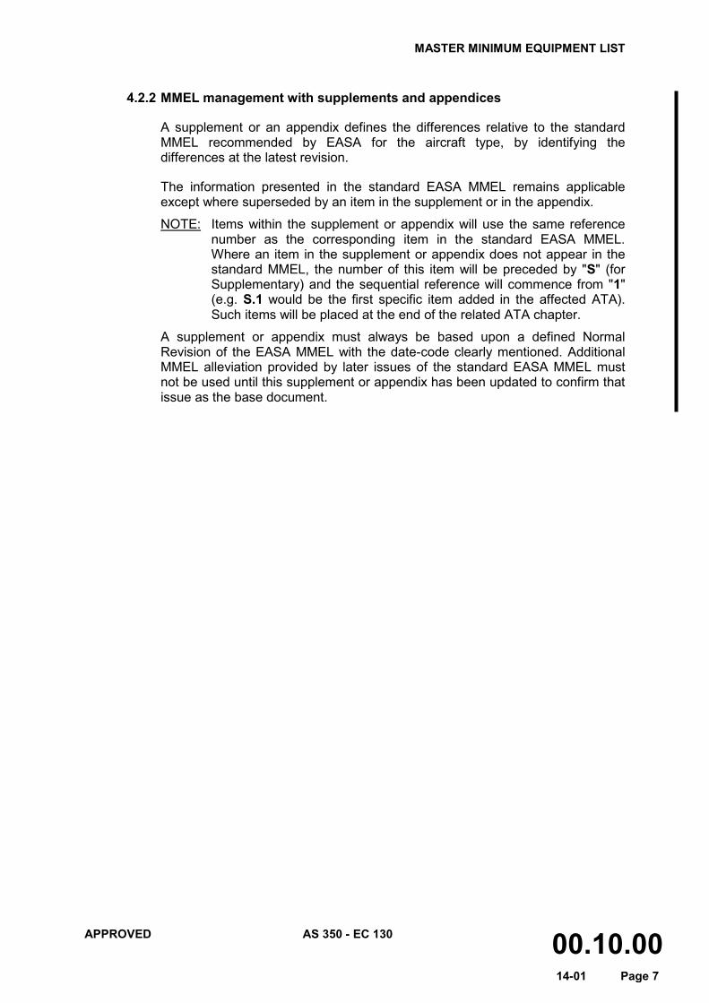
4.2.2 MMEL management with supplements and appendices
A supplement or an appendix defines the differences relative to the standard MMEL recommended by EASA for the aircraft type, by identifying the differences at the latest revision.
The information presented in the standard EASA MMEL remains applicable except where superseded by an item in the supplement or in the appendix.
NOTE: Items within the supplement or appendix will use the same reference number as the corresponding item in the standard EASA MMEL. Where an item in the supplement or appendix does not appear in the standard MMEL, the number of this item will be preceded by "S" (for Supplementary) and the sequential reference will commence from "1" (e.g. S.1 would be the first specific item added in the affected ATA). Such items will be placed at the end of the related ATA chapter.
A supplement or appendix must always be based upon a defined Normal Revision of the EASA MMEL with the date-code clearly mentioned. Additional MMEL alleviation provided by later issues of the standard EASA MMEL must not be used until this supplement or appendix has been updated to confirm that issue as the base document.

MASTER MINIMUM EQUIPMENT LIST
APPROVED AS 350 - EC 130 18.00.00 14-01 Page 1
(1) SYSTEMS AND SEQUENCE NUMBERS
(2) RECTIFICATION INTERVAL
(3) NUMBER INSTALLED
(4) NUMBER REQUIRED FOR DISPATCH
ITEM (5) REMARKS OR EXCEPTIONS
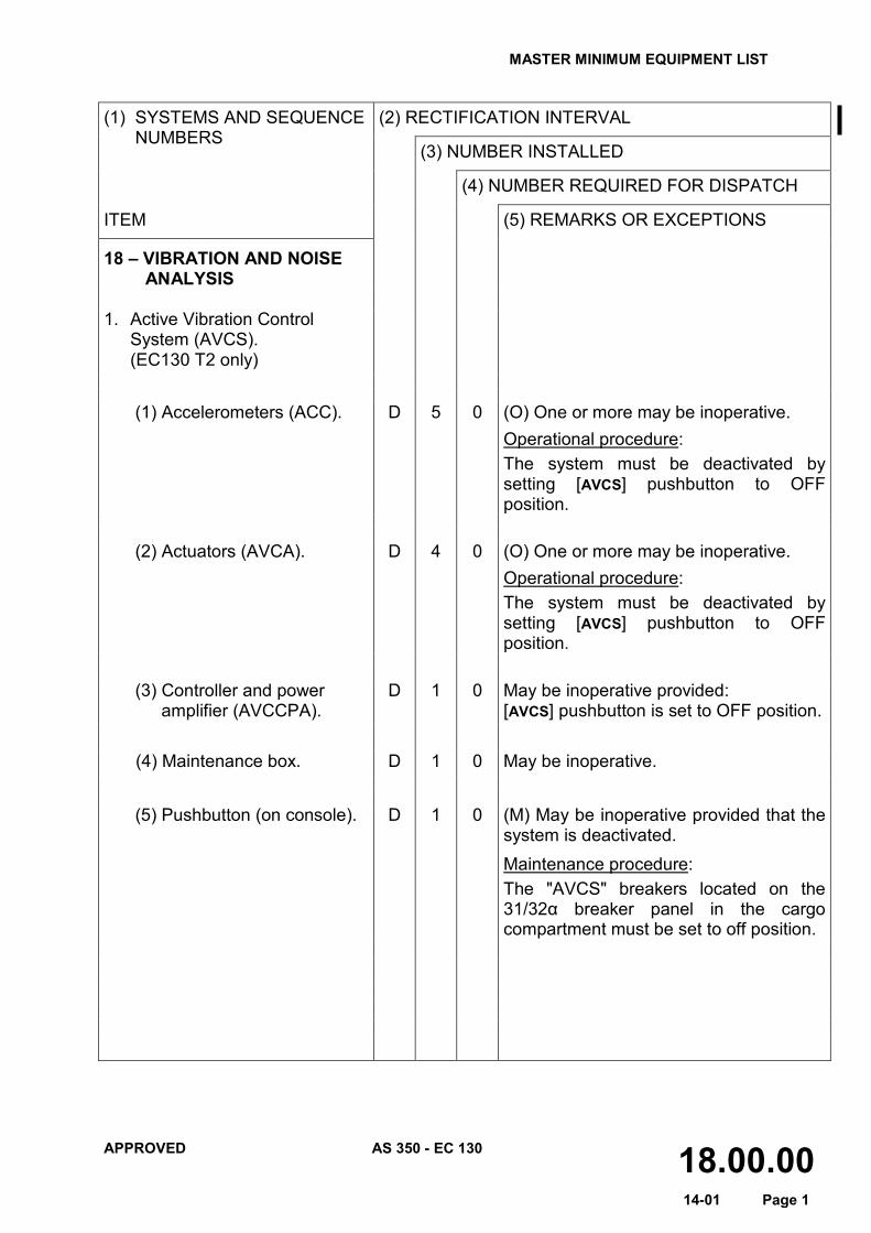
18 – VIBRATION AND NOISE ANALYSIS
1. Active Vibration Control
System (AVCS). (EC130 T2 only)
(1) Accelerometers (ACC). D 5 0 (O) One or more may be inoperative.
Operational procedure: The system must be deactivated by setting [AVCS] pushbutton to OFF position.
(2) Actuators (AVCA). D 4 0 (O) One or more may be inoperative.
Operational procedure: The system must be deactivated by setting [AVCS] pushbutton to OFF position.
(3) Controller and power
amplifier (AVCCPA). D 1 0 May be inoperative provided:
[AVCS] pushbutton is set to OFF position. (4) Maintenance box. D 1 0 May be inoperative. (5) Pushbutton (on console). D 1 0 (M) May be inoperative provided that the
system is deactivated. Maintenance procedure: The "AVCS" breakers located on the 31/32α breaker panel in the cargo compartment must be set to off position.
MASTER MINIMUM EQUIPMENT LIST
APPROVED AS 350 - EC 130 18.00.00 14-01 Page 2
(1) SYSTEMS AND SEQUENCE NUMBERS
(2) RECTIFICATION INTERVAL
(3) NUMBER INSTALLED
(4) NUMBER REQUIRED FOR DISPATCH
ITEM (5) REMARKS OR EXCEPTIONS
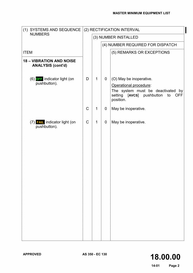
18 – VIBRATION AND NOISE ANALYSIS (cont'd)
(6) OFF indicator light (on
pushbutton). D 1 0 (O) May be inoperative.
Operational procedure: The system must be deactivated by setting [AVCS] pushbutton to OFF position.
C 1 0 May be inoperative. (7) FAIL indicator light (on
pushbutton). C 1 0 May be inoperative.
MASTER MINIMUM EQUIPMENT LIST
APPROVED AS 350 - EC 130 21.00.00 14-01 Page 1
(1) SYSTEMS AND SEQUENCE NUMBERS
(2) RECTIFICATION INTERVAL
(3) NUMBER INSTALLED
(4) NUMBER REQUIRED FOR DISPATCH
ITEM (5) REMARKS OR EXCEPTIONS
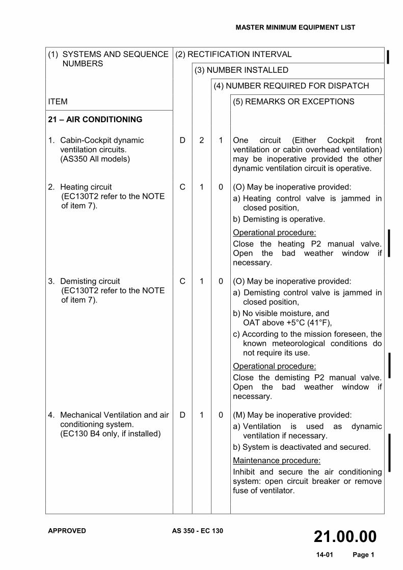
21 – AIR CONDITIONING
1. Cabin-Cockpit dynamic
ventilation circuits. (AS350 All models)
D 2 1 One circuit (Either Cockpit front ventilation or cabin overhead ventilation) may be inoperative provided the other dynamic ventilation circuit is operative.
2. Heating circuit
(EC130T2 refer to the NOTE of item 7).
C 1 0 (O) May be inoperative provided: a) Heating control valve is jammed in
closed position, b) Demisting is operative. Operational procedure: Close the heating P2 manual valve. Open the bad weather window if necessary.
3. Demisting circuit
(EC130T2 refer to the NOTE of item 7).
C 1 0 (O) May be inoperative provided: a) Demisting control valve is jammed in
closed position, b) No visible moisture, and OAT above +5°C (41°F), c) According to the mission foreseen, the
known meteorological conditions do not require its use.
Operational procedure: Close the demisting P2 manual valve. Open the bad weather window if necessary.
4. Mechanical Ventilation and air
conditioning system. (EC130 B4 only, if installed)
D 1 0 (M) May be inoperative provided: a) Ventilation is used as dynamic
ventilation if necessary. b) System is deactivated and secured. Maintenance procedure: Inhibit and secure the air conditioning system: open circuit breaker or remove fuse of ventilator.
MASTER MINIMUM EQUIPMENT LIST
APPROVED AS 350 - EC 130 21.00.00 14-01 Page 2
(1) SYSTEMS AND SEQUENCE NUMBERS
(2) RECTIFICATION INTERVAL
(3) NUMBER INSTALLED
(4) NUMBER REQUIRED FOR DISPATCH
ITEM (5) REMARKS OR EXCEPTIONS
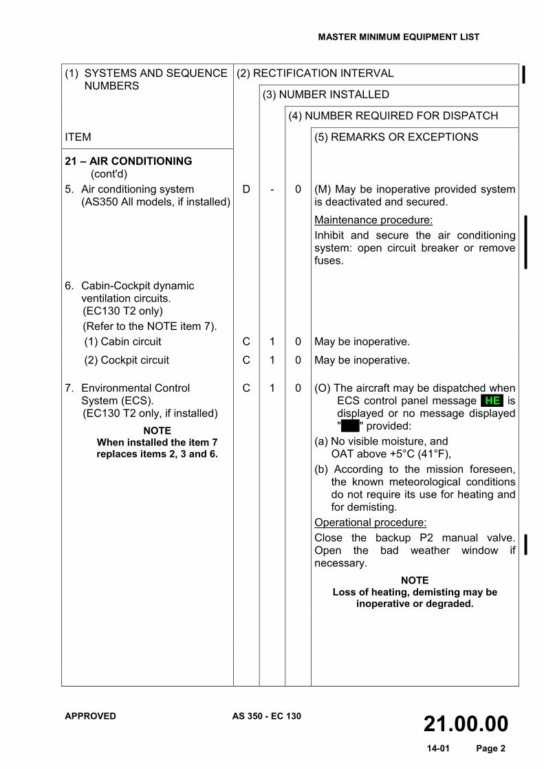
21 – AIR CONDITIONING (cont'd)
5. Air conditioning system (AS350 All models, if installed)
D - 0 (M) May be inoperative provided system is deactivated and secured. Maintenance procedure: Inhibit and secure the air conditioning system: open circuit breaker or remove fuses.
6. Cabin-Cockpit dynamic
ventilation circuits. (EC130 T2 only) (Refer to the NOTE item 7).
(1) Cabin circuit C 1 0 May be inoperative.
(2) Cockpit circuit C 1 0 May be inoperative. 7. Environmental Control
System (ECS). (EC130 T2 only, if installed)
NOTE When installed the item 7 replaces items 2, 3 and 6.
C 1 0 (O) The aircraft may be dispatched when ECS control panel message HE is displayed or no message displayed " " provided:
(a) No visible moisture, and OAT above +5°C (41°F),
(b) According to the mission foreseen, the known meteorological conditions do not require its use for heating and for demisting.
Operational procedure: Close the backup P2 manual valve. Open the bad weather window if necessary.
NOTE Loss of heating, demisting may be
inoperative or degraded.
MASTER MINIMUM EQUIPMENT LIST
APPROVED AS 350 - EC 130 21.00.00 14-01 Page 3
(1) SYSTEMS AND SEQUENCE NUMBERS
(2) RECTIFICATION INTERVAL
(3) NUMBER INSTALLED
(4) NUMBER REQUIRED FOR DISPATCH
ITEM (5) REMARKS OR EXCEPTIONS
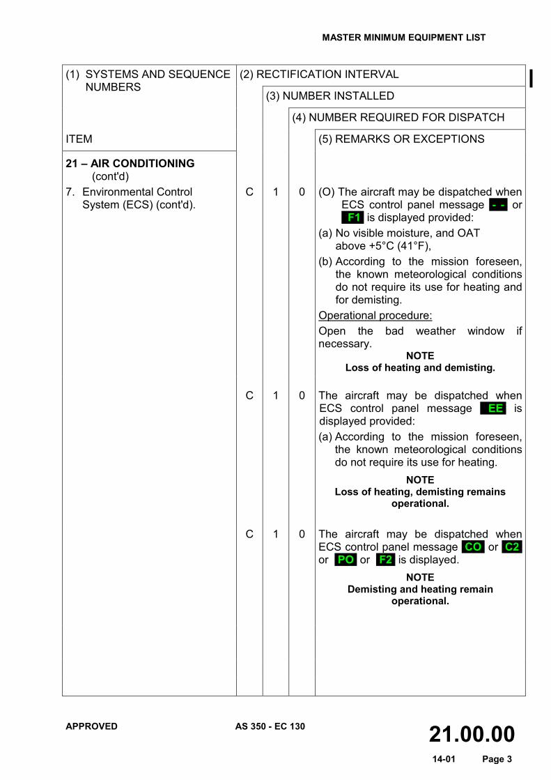
21 – AIR CONDITIONING (cont'd)
7. Environmental Control System (ECS) (cont'd).
C 1 0 (O) The aircraft may be dispatched when ECS control panel message - - or F1 is displayed provided:
(a) No visible moisture, and OAT above +5°C (41°F),
(b) According to the mission foreseen, the known meteorological conditions do not require its use for heating and for demisting.
Operational procedure: Open the bad weather window if necessary.
NOTE Loss of heating and demisting.
C 1 0 The aircraft may be dispatched when
ECS control panel message EE is displayed provided: (a) According to the mission foreseen,
the known meteorological conditions do not require its use for heating.
NOTE Loss of heating, demisting remains
operational.
C 1 0 The aircraft may be dispatched when ECS control panel message CO or C2 or PO or F2 is displayed.
NOTE Demisting and heating remain
operational.
MASTER MINIMUM EQUIPMENT LIST
APPROVED AS 350 - EC 130 21.00.00 14-01 Page 4
(1) SYSTEMS AND SEQUENCE
NUMBERS
(2) RECTIFICATION INTERVAL
(3) NUMBER INSTALLED
(4) NUMBER REQUIRED FOR DISPATCH
ITEM (5) REMARKS OR EXCEPTIONS
21 – AIR CONDITIONING (cont'd)
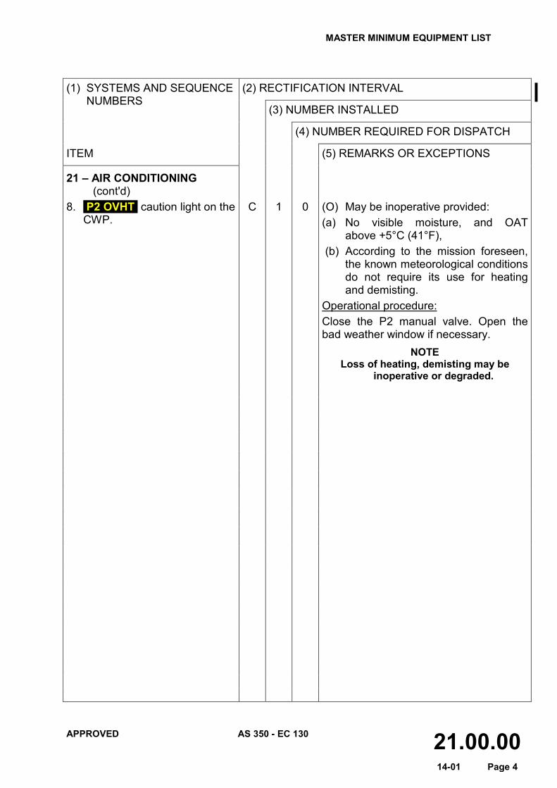
8. P2 OVHT caution light on the CWP.
C 1 0 (O) May be inoperative provided: (a) No visible moisture, and OAT
above +5°C (41°F), (b) According to the mission foreseen,
the known meteorological conditions do not require its use for heating and demisting.
Operational procedure: Close the P2 manual valve. Open the bad weather window if necessary.
NOTE Loss of heating, demisting may be
inoperative or degraded.
MASTER MINIMUM EQUIPMENT LIST
APPROVED AS 350 - EC 130 22.00.00 14-01 Page 1
(1) SYSTEMS AND SEQUENCE NUMBERS
(2) RECTIFICATION INTERVAL
(3) NUMBER INSTALLED
(4) NUMBER REQUIRED FOR DISPATCH
ITEM (5) REMARKS OR EXCEPTIONS
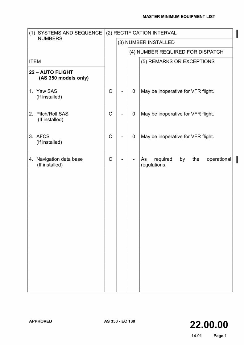
22 – AUTO FLIGHT (AS 350 models only) 1. Yaw SAS
(If installed) C - 0 May be inoperative for VFR flight.
2. Pitch/Roll SAS
(If installed) C - 0 May be inoperative for VFR flight.
3. AFCS
(If installed) C - 0 May be inoperative for VFR flight.
4. Navigation data base (If installed)
C - - As required by the operational regulations.

MASTER MINIMUM EQUIPMENT LIST
APPROVED AS 350 - EC 130 23.00.00 14-01 Page 1
(1) SYSTEMS AND SEQUENCE NUMBERS
(2) RECTIFICATION INTERVAL
(3) NUMBER INSTALLED
(4) NUMBER REQUIRED FOR DISPATCH
ITEM (5) REMARKS OR EXCEPTIONS
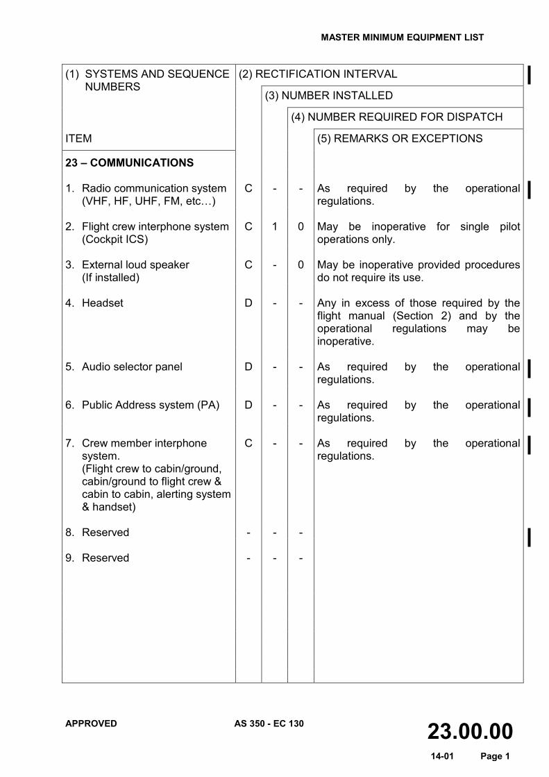
23 – COMMUNICATIONS 1. Radio communication system
(VHF, HF, UHF, FM, etc…) C - - As required by the operational
regulations. 2. Flight crew interphone system
(Cockpit ICS) C 1 0 May be inoperative for single pilot
operations only. 3. External loud speaker
(If installed) C - 0 May be inoperative provided procedures
do not require its use. 4. Headset D - - Any in excess of those required by the
flight manual (Section 2) and by the operational regulations may be inoperative.
5. Audio selector panel D - - As required by the operational
regulations. 6. Public Address system (PA) D - - As required by the operational
regulations. 7. Crew member interphone
system. (Flight crew to cabin/ground, cabin/ground to flight crew & cabin to cabin, alerting system & handset)
C - - As required by the operational regulations.
8. Reserved - - - 9. Reserved
- - -

MASTER MINIMUM EQUIPMENT LIST
APPROVED AS 350 - EC 130 24.00.00 14-01 Page 1
(1) SYSTEMS AND SEQUENCE NUMBERS
(2) RECTIFICATION INTERVAL
(3) NUMBER INSTALLED
(4) NUMBER REQUIRED FOR DISPATCH
ITEM (5) REMARKS OR EXCEPTIONS
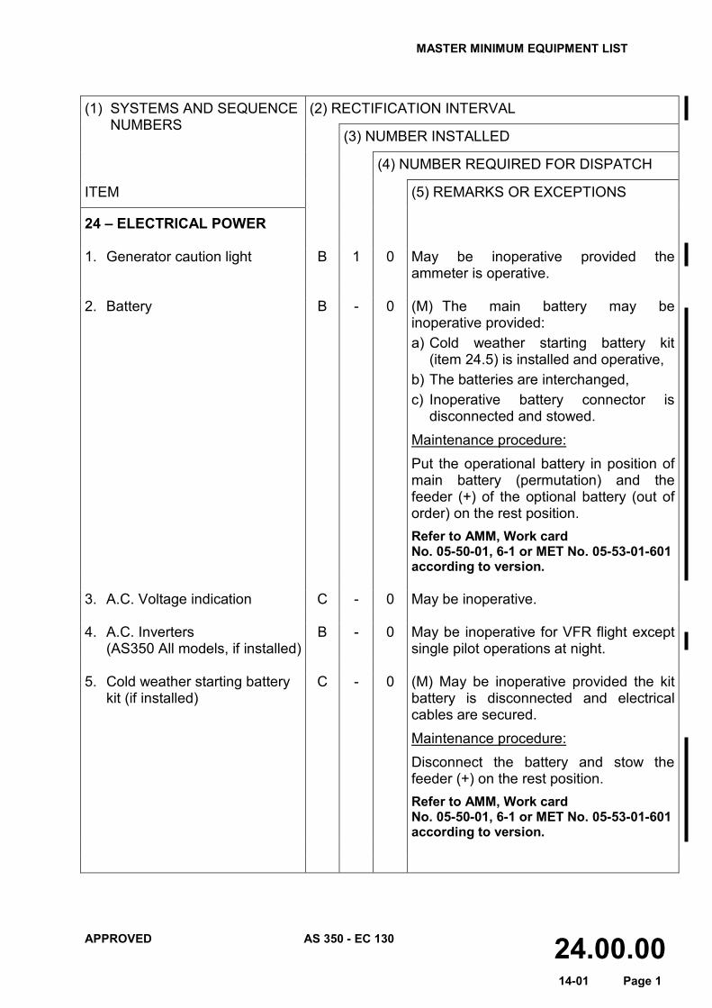
24 – ELECTRICAL POWER 1. Generator caution light B 1 0 May be inoperative provided the
ammeter is operative. 2. Battery B - 0 (M) The main battery may be
inoperative provided: a) Cold weather starting battery kit
(item 24.5) is installed and operative, b) The batteries are interchanged, c) Inoperative battery connector is
disconnected and stowed. Maintenance procedure: Put the operational battery in position of main battery (permutation) and the feeder (+) of the optional battery (out of order) on the rest position. Refer to AMM, Work card No. 05-50-01, 6-1 or MET No. 05-53-01-601 according to version.
3. A.C. Voltage indication C - 0 May be inoperative. 4. A.C. Inverters (AS350 All models, if installed)
B - 0 May be inoperative for VFR flight except single pilot operations at night.
5. Cold weather starting battery
kit (if installed) C - 0 (M) May be inoperative provided the kit
battery is disconnected and electrical cables are secured. Maintenance procedure: Disconnect the battery and stow the feeder (+) on the rest position. Refer to AMM, Work card No. 05-50-01, 6-1 or MET No. 05-53-01-601 according to version.

MASTER MINIMUM EQUIPMENT LIST
APPROVED AS 350 - EC 130 25.00.00 14-01 Page 1
(1) SYSTEMS AND SEQUENCE NUMBERS
(2) RECTIFICATION INTERVAL
(3) NUMBER INSTALLED
(4) NUMBER REQUIRED FOR DISPATCH
ITEM (5) REMARKS OR EXCEPTIONS
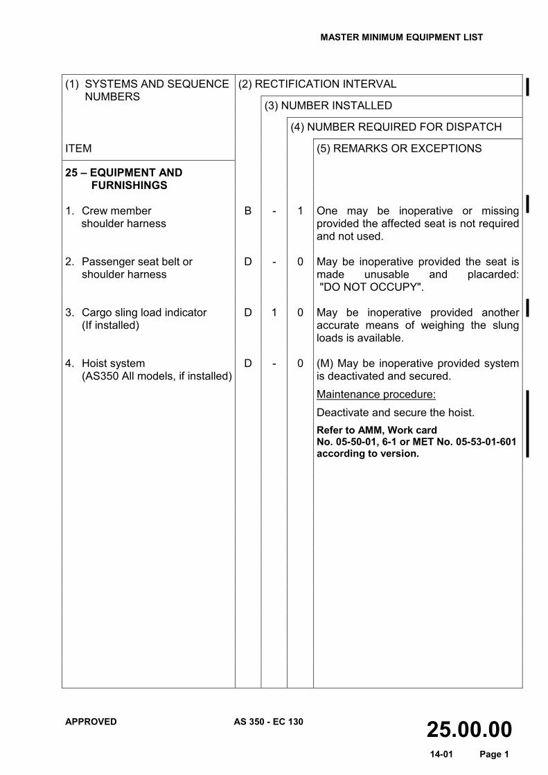
25 – EQUIPMENT AND FURNISHINGS
1. Crew member
shoulder harness B - 1 One may be inoperative or missing
provided the affected seat is not required and not used.
2. Passenger seat belt or
shoulder harness D - 0 May be inoperative provided the seat is
made unusable and placarded: "DO NOT OCCUPY".
3. Cargo sling load indicator
(If installed) D 1 0 May be inoperative provided another
accurate means of weighing the slung loads is available.
4. Hoist system
(AS350 All models, if installed) D - 0 (M) May be inoperative provided system
is deactivated and secured. Maintenance procedure: Deactivate and secure the hoist. Refer to AMM, Work card No. 05-50-01, 6-1 or MET No. 05-53-01-601 according to version.
MASTER MINIMUM EQUIPMENT LIST
APPROVED AS 350 - EC 130 25.00.00 14-01 Page 2
(1) SYSTEMS AND SEQUENCE NUMBERS
(2) RECTIFICATION INTERVAL
(3) NUMBER INSTALLED
(4) NUMBER REQUIRED FOR DISPATCH
ITEM (5) REMARKS OR EXCEPTIONS
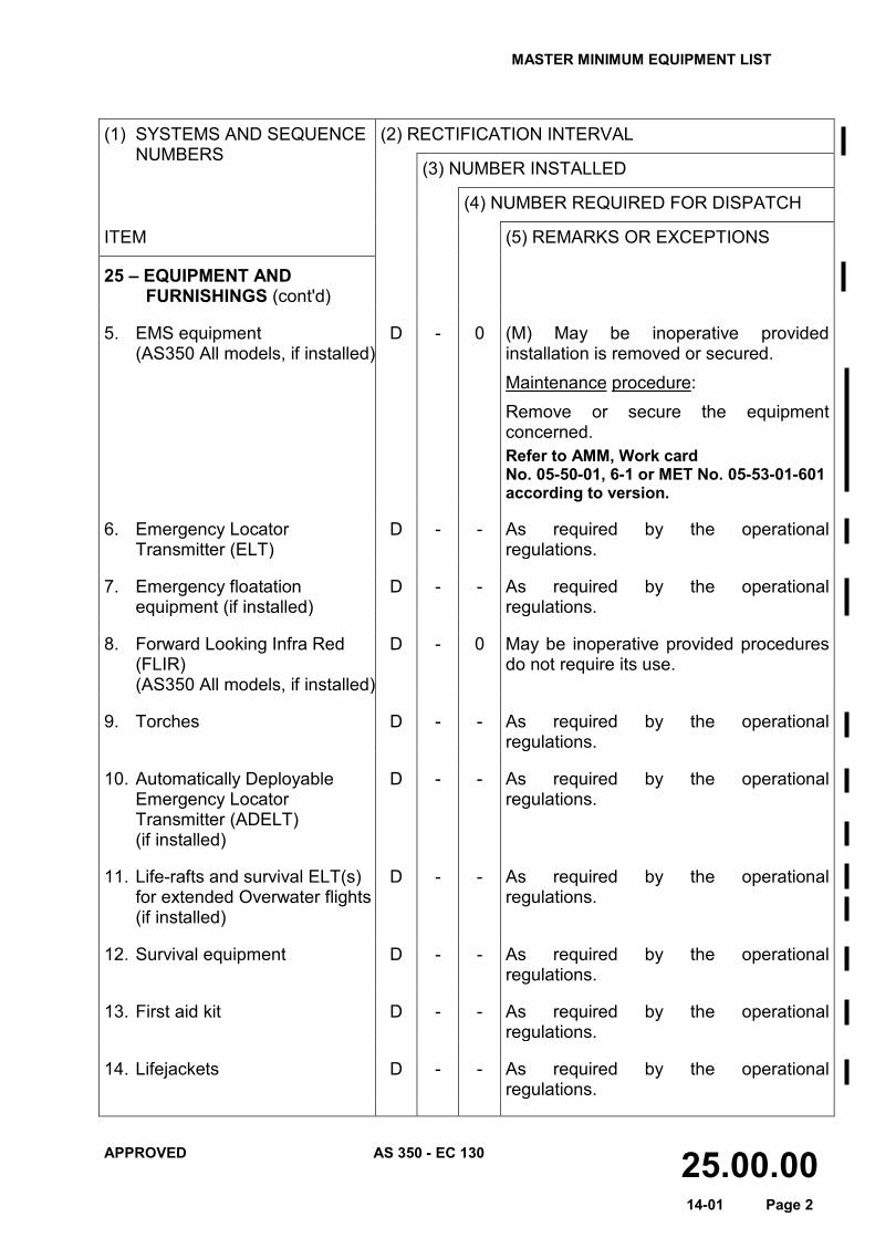
25 – EQUIPMENT AND FURNISHINGS (cont'd)
5. EMS equipment
(AS350 All models, if installed) D - 0 (M) May be inoperative provided
installation is removed or secured. Maintenance procedure: Remove or secure the equipment concerned. Refer to AMM, Work card No. 05-50-01, 6-1 or MET No. 05-53-01-601 according to version.
6. Emergency Locator
Transmitter (ELT) D - - As required by the operational
regulations. 7. Emergency floatation
equipment (if installed) D - - As required by the operational
regulations. 8. Forward Looking Infra Red
(FLIR) (AS350 All models, if installed)
D - 0 May be inoperative provided procedures do not require its use.
9. Torches D - - As required by the operational
regulations. 10. Automatically Deployable
Emergency Locator Transmitter (ADELT) (if installed)
D - - As required by the operational regulations.
11. Life-rafts and survival ELT(s)
for extended Overwater flights (if installed)
D - - As required by the operational regulations.
12. Survival equipment D - - As required by the operational
regulations. 13. First aid kit D - - As required by the operational
regulations. 14. Lifejackets D - - As required by the operational
regulations.
MASTER MINIMUM EQUIPMENT LIST
APPROVED AS 350 - EC 130 26.00.00 14-01 Page 1
(1) SYSTEMS AND SEQUENCE NUMBERS
(2) RECTIFICATION INTERVAL
(3) NUMBER INSTALLED
(4) NUMBER REQUIRED FOR DISPATCH
ITEM (5) REMARKS OR EXCEPTIONS
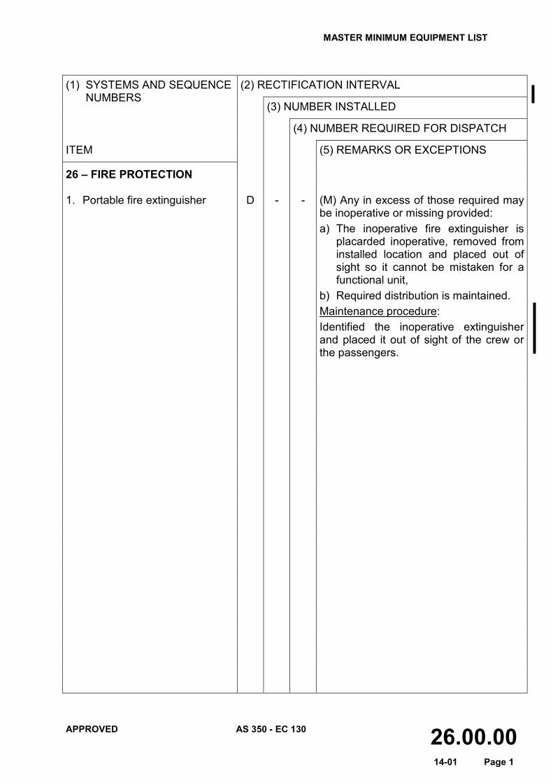
26 – FIRE PROTECTION 1. Portable fire extinguisher D - - (M) Any in excess of those required may
be inoperative or missing provided: a) The inoperative fire extinguisher is
placarded inoperative, removed from installed location and placed out of sight so it cannot be mistaken for a functional unit,
b) Required distribution is maintained. Maintenance procedure:
Identified the inoperative extinguisher and placed it out of sight of the crew or the passengers.

MASTER MINIMUM EQUIPMENT LIST
APPROVED AS 350 - EC 130 28.00.00 14-01 Page 1
(1) SYSTEMS AND SEQUENCE NUMBERS
(2) RECTIFICATION INTERVAL
(3) NUMBER INSTALLED
(4) NUMBER REQUIRED FOR DISPATC
ITEM (5) REMARKS OR EXCEPTIONS
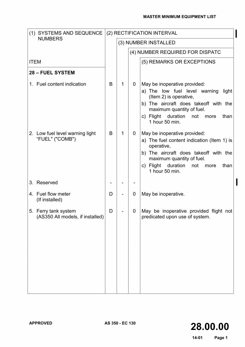
28 – FUEL SYSTEM 1. Fuel content indication
B 1 0 May be inoperative provided: a) The low fuel level warning light
(Item 2) is operative, b) The aircraft does takeoff with the
maximum quantity of fuel. c) Flight duration not more than
1 hour 50 min. 2. Low fuel level warning light “FUEL" ("COMB")
B 1 0 May be inoperative provided: a) The fuel content indication (Item 1) is
operative, b) The aircraft does takeoff with the
maximum quantity of fuel. c) Flight duration not more than
1 hour 50 min. 3. Reserved - - - 4. Fuel flow meter
(If installed) D - 0 May be inoperative.
5. Ferry tank system (AS350 All models, if installed)
D - 0 May be inoperative provided flight not predicated upon use of system.

MASTER MINIMUM EQUIPMENT LIST
APPROVED AS 350 - EC 130 30.00.00 14-01 Page 1
(1) SYSTEMS AND SEQUENCE NUMBERS
(2) RECTIFICATION INTERVAL
(3) NUMBER INSTALLED
(4) NUMBER REQUIRED FOR DISPATCH
ITEM (5) REMARKS OR EXCEPTIONS
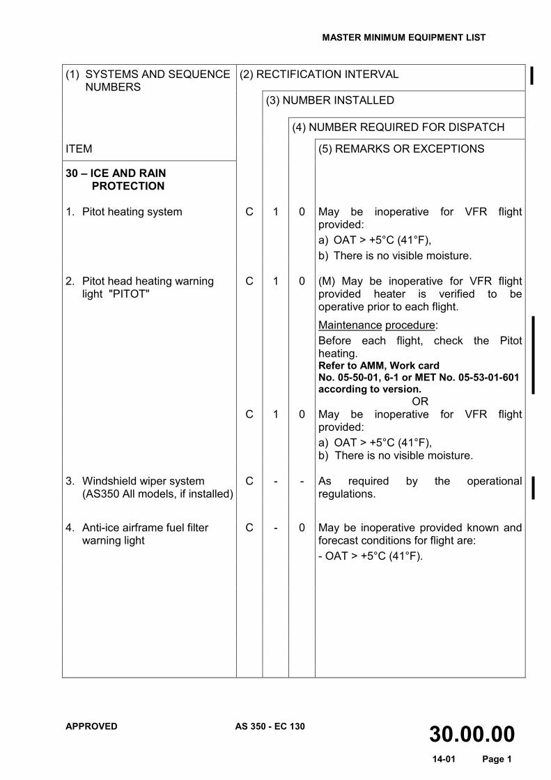
30 – ICE AND RAIN PROTECTION
1. Pitot heating system C 1 0 May be inoperative for VFR flight
provided: a) OAT > +5°C (41°F), b) There is no visible moisture.
2. Pitot head heating warning
light "PITOT" C 1 0 (M) May be inoperative for VFR flight
provided heater is verified to be operative prior to each flight. Maintenance procedure: Before each flight, check the Pitot heating. Refer to AMM, Work card No. 05-50-01, 6-1 or MET No. 05-53-01-601 according to version.
OR C 1 0 May be inoperative for VFR flight
provided: a) OAT > +5°C (41°F), b) There is no visible moisture.
3. Windshield wiper system (AS350 All models, if installed)
C - - As required by the operational regulations.
4. Anti-ice airframe fuel filter warning light
C - 0 May be inoperative provided known and forecast conditions for flight are: - OAT > +5°C (41°F).

MASTER MINIMUM EQUIPMENT LIST
APPROVED AS 350 - EC 130 31.00.00 14-01 Page 1
(1) SYSTEMS AND SEQUENCE NUMBERS
(2) RECTIFICATION INTERVAL
(3) NUMBER INSTALLED
(4) NUMBER REQUIRED FOR DISPATCH
ITEM (5) REMARKS OR EXCEPTIONS
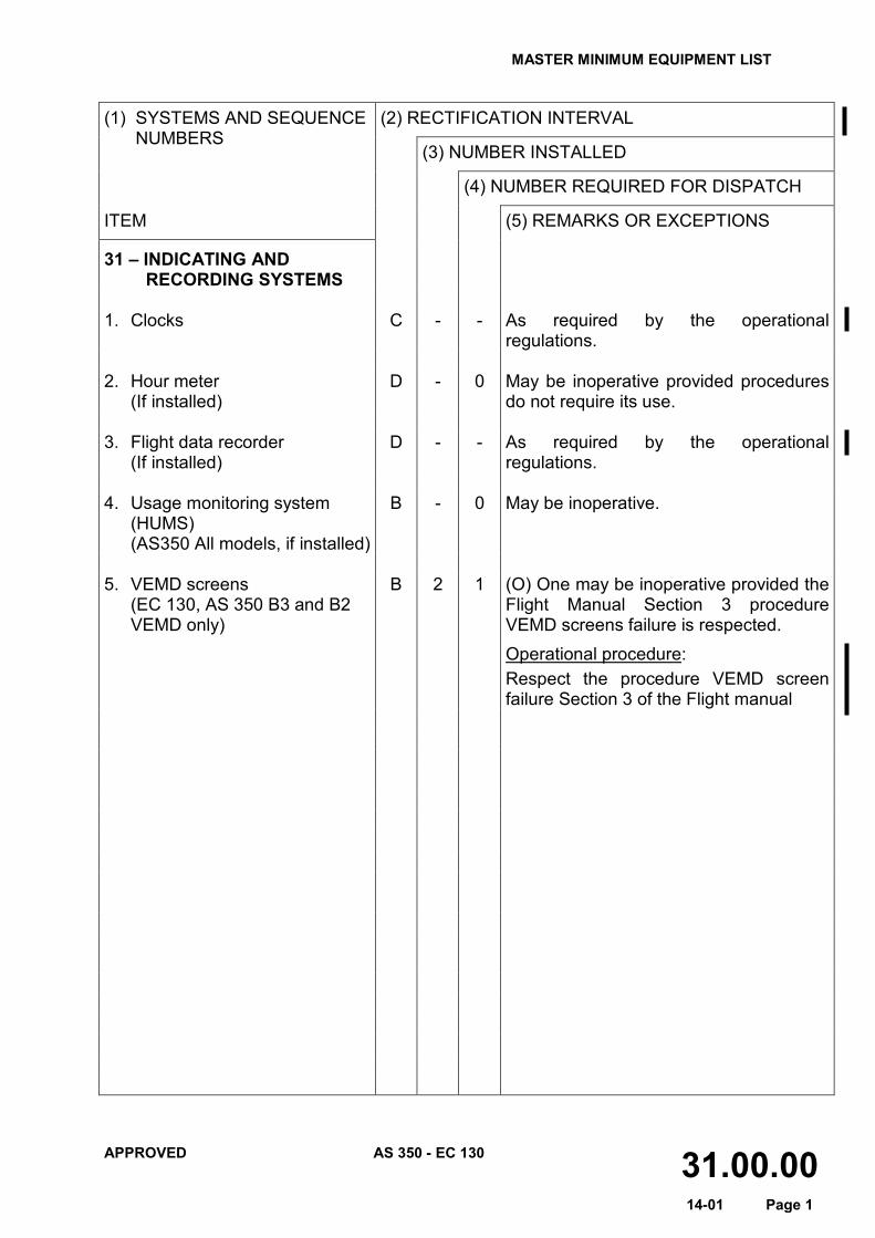
31 – INDICATING AND RECORDING SYSTEMS
1. Clocks C - - As required by the operational
regulations. 2. Hour meter
(If installed) D - 0 May be inoperative provided procedures
do not require its use. 3. Flight data recorder
(If installed) D - - As required by the operational
regulations. 4. Usage monitoring system
(HUMS) (AS350 All models, if installed)
B - 0 May be inoperative.
5. VEMD screens
(EC 130, AS 350 B3 and B2 VEMD only)
B 2 1 (O) One may be inoperative provided the Flight Manual Section 3 procedure VEMD screens failure is respected. Operational procedure: Respect the procedure VEMD screen failure Section 3 of the Flight manual

MASTER MINIMUM EQUIPMENT LIST
APPROVED AS 350 - EC 130 33.00.00 14-01 Page 1
(1) SYSTEMS AND SEQUENCE NUMBERS
(2) RECTIFICATION INTERVAL
(3) NUMBER INSTALLED
(4) NUMBER REQUIRED FOR DISPATCH
ITEM (5) REMARKS OR EXCEPTIONS
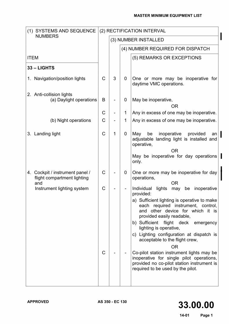
33 – LIGHTS 1. Navigation/position lights C 3 0 One or more may be inoperative for
daytime VMC operations. 2. Anti-collision lights
(a) Daylight operations B
C
- -
0
1
May be inoperative, OR
Any in excess of one may be inoperative. (b) Night operations C - 1 Any in excess of one may be inoperative.
3. Landing light C
1
0
May be inoperative provided an adjustable landing light is installed and operative,
OR May be inoperative for day operations only.
4. Cockpit / instrument panel / flight compartment lighting and Instrument lighting system
C
C
- -
0 -
One or more may be inoperative for day operations,
OR Individual lights may be inoperative provided: a) Sufficient lighting is operative to make
each required instrument, control, and other device for which it is provided easily readable,
b) Sufficient flight deck emergency lighting is operative,
c) Lighting configuration at dispatch is acceptable to the flight crew,
OR C - - Co-pilot station instrument lights may be
inoperative for single pilot operations, provided no co-pilot station instrument is required to be used by the pilot.
MASTER MINIMUM EQUIPMENT LIST
APPROVED AS 350 - EC 130 33.00.00 14-01 Page 2
(1) SYSTEMS AND SEQUENCE NUMBERS
(2) RECTIFICATION INTERVAL
(3) NUMBER INSTALLED
(4) NUMBER REQUIRED FOR DISPATCH
ITEM (5) REMARKS OR EXCEPTIONS
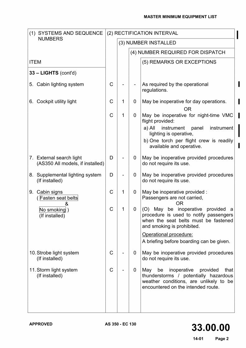
33 – LIGHTS (cont'd) 5. Cabin lighting system
C
-
-
As required by the operational regulations.
6. Cockpit utility light C 1 0 May be inoperative for day operations. OR C 1 0 May be inoperative for night-time VMC
flight provided: a) All instrument panel instrument
lighting is operative, b) One torch per flight crew is readily
available and operative. 7. External search light
(AS350 All models, if installed) D - 0 May be inoperative provided procedures
do not require its use. 8. Supplemental lighting system
(If installed) D - 0 May be inoperative provided procedures
do not require its use. 9. Cabin signs ( Fasten seat belts
& No smoking ) (If installed)
C
C
1
1
0
0
May be inoperative provided : Passengers are not carried,
OR (O) May be inoperative provided a procedure is used to notify passengers when the seat belts must be fastened and smoking is prohibited. Operational procedure: A briefing before boarding can be given.
10. Strobe light system
(If installed) C - 0 May be inoperative provided procedures
do not require its use. 11. Storm light system
(If installed) C - 0 May be inoperative provided that
thunderstorms / potentially hazardous weather conditions, are unlikely to be encountered on the intended route.
MASTER MINIMUM EQUIPMENT LIST
APPROVED AS 350 - EC 130 34.00.00 14-01 Page 1
(1) SYSTEMS AND SEQUENCE NUMBERS
(2) RECTIFICATION INTERVAL
(3) NUMBER INSTALLED
(4) NUMBER REQUIRED FOR DISPATCH
ITEM (5) REMARKS OR EXCEPTIONS
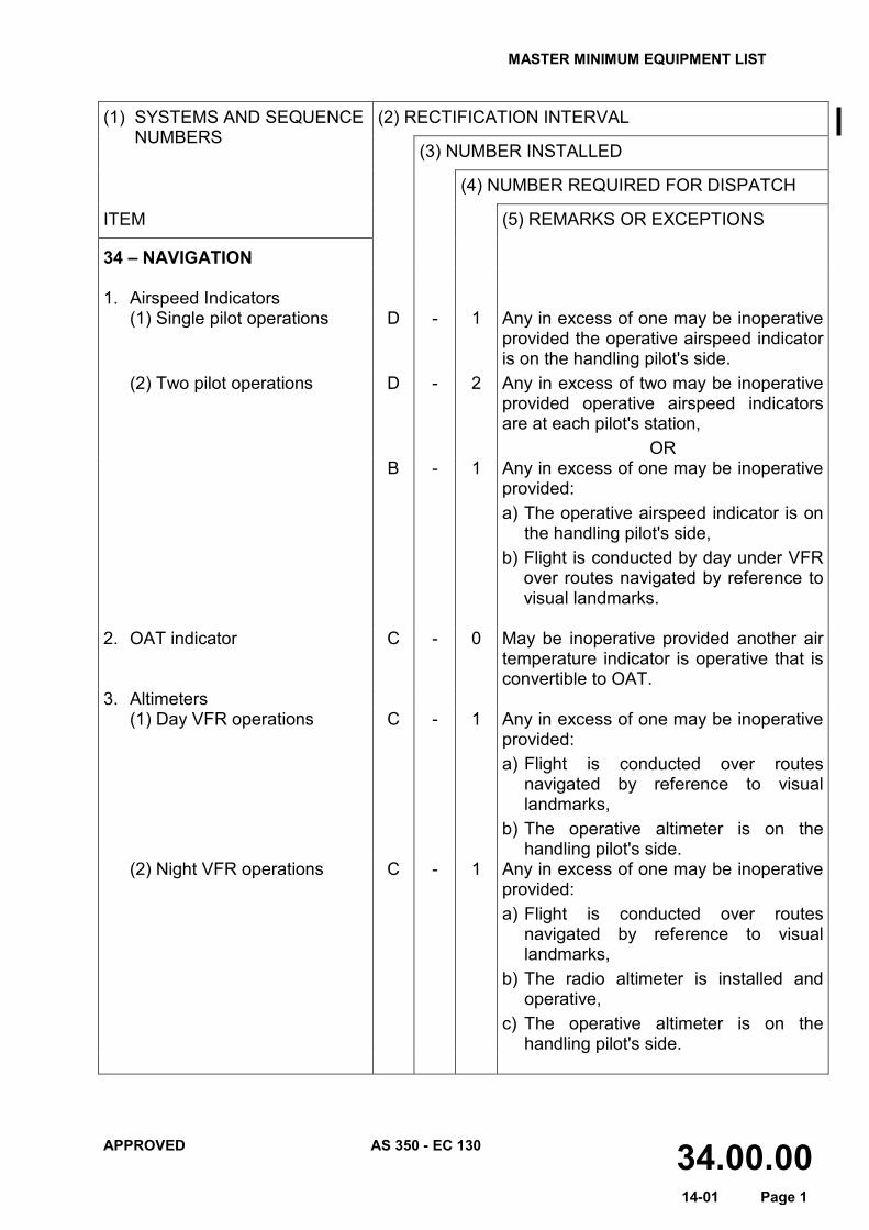
34 – NAVIGATION 1. Airspeed Indicators
(1) Single pilot operations D - 1 Any in excess of one may be inoperative provided the operative airspeed indicator is on the handling pilot's side.
(2) Two pilot operations D - 2 Any in excess of two may be inoperative provided operative airspeed indicators are at each pilot's station,
OR B - 1 Any in excess of one may be inoperative
provided: a) The operative airspeed indicator is on
the handling pilot's side, b) Flight is conducted by day under VFR
over routes navigated by reference to visual landmarks.
2. OAT indicator C - 0 May be inoperative provided another air
temperature indicator is operative that is convertible to OAT.
3. Altimeters (1) Day VFR operations C - 1 Any in excess of one may be inoperative
provided: a) Flight is conducted over routes
navigated by reference to visual landmarks,
b) The operative altimeter is on the handling pilot's side.
(2) Night VFR operations C - 1 Any in excess of one may be inoperative provided: a) Flight is conducted over routes
navigated by reference to visual landmarks,
b) The radio altimeter is installed and operative,
c) The operative altimeter is on the handling pilot's side.
MASTER MINIMUM EQUIPMENT LIST
APPROVED AS 350 - EC 130 34.00.00 14-01 Page 2
(1) SYSTEMS AND SEQUENCE NUMBERS
(2) RECTIFICATION INTERVAL
(3) NUMBER INSTALLED
(4) NUMBER REQUIRED FOR DISPATCH
ITEM (5) REMARKS OR EXCEPTIONS
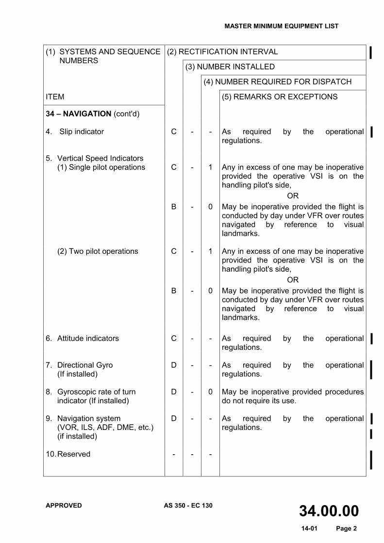
34 – NAVIGATION (cont'd) 4. Slip indicator C - - As required by the operational
regulations. 5. Vertical Speed Indicators
(1) Single pilot operations C - 1 Any in excess of one may be inoperative provided the operative VSI is on the handling pilot's side,
OR B - 0 May be inoperative provided the flight is
conducted by day under VFR over routes navigated by reference to visual landmarks.
(2) Two pilot operations C - 1 Any in excess of one may be inoperative
provided the operative VSI is on the handling pilot's side,
OR B - 0 May be inoperative provided the flight is
conducted by day under VFR over routes navigated by reference to visual landmarks.
6. Attitude indicators C - - As required by the operational
regulations. 7. Directional Gyro (If installed)
D - - As required by the operational regulations.
8. Gyroscopic rate of turn
indicator (If installed) D - 0 May be inoperative provided procedures
do not require its use. 9. Navigation system
(VOR, ILS, ADF, DME, etc.) (if installed)
D - - As required by the operational regulations.
10. Reserved - - -
MASTER MINIMUM EQUIPMENT LIST
APPROVED AS 350 - EC 130 34.00.00 14-01 Page 3
(1) SYSTEMS AND SEQUENCE NUMBERS
(2) RECTIFICATION INTERVAL
(3) NUMBER INSTALLED
(4) NUMBER REQUIRED FOR DISPATCH
ITEM (5) REMARKS OR EXCEPTIONS
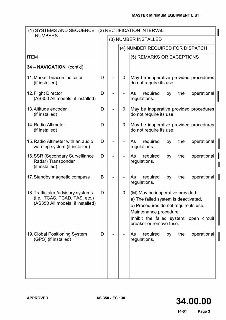
34 – NAVIGATION (cont'd) 11. Marker beacon indicator
(if installed) D - 0 May be inoperative provided procedures
do not require its use. 12. Flight Director
(AS350 All models, if installed) D - - As required by the operational
regulations. 13. Altitude encoder (if installed)
D - 0 May be inoperative provided procedures do not require its use.
14. Radio Altimeter (if installed)
D - 0 May be inoperative provided procedures do not require its use.
15. Radio Altimeter with an audio
warning system (if installed) D - - As required by the operational
regulations.
16. SSR (Secondary Surveillance Radar) Transponder (if installed)
D - - As required by the operational regulations.
17. Standby magnetic compass B - - As required by the operational
regulations. 18. Traffic alert/advisory systems
(i.e., TCAS, TCAD, TAS, etc.) (AS350 All models, if installed)
D - 0 (M) May be inoperative provided: a) The failed system is deactivated, b) Procedures do not require its use. Maintenance procedure: Inhibit the failed system: open circuit breaker or remove fuse.
19. Global Positioning System
(GPS) (if installed) D - - As required by the operational
regulations.

MASTER MINIMUM EQUIPMENT LIST
APPROVED AS 350 - EC 130 35.00.00 14-01 Page 1
(1) SYSTEMS AND SEQUENCE NUMBERS
(2) RECTIFICATION INTERVAL
(3) NUMBER INSTALLED
(4) NUMBER REQUIRED FOR DISPATCH
ITEM (5) REMARKS OR EXCEPTIONS
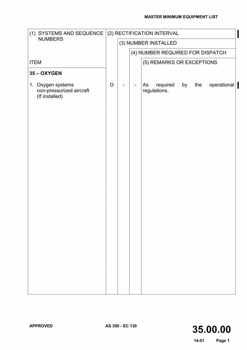
35 – OXYGEN 1. Oxygen systems non-pressurized aircraft (If installed)
D - - As required by the operational regulations.

MASTER MINIMUM EQUIPMENT LIST
APPROVED AS 350 - EC 130 52.00.00 14-01 Page 1
(1) SYSTEMS AND SEQUENCE NUMBERS
(2) RECTIFICATION INTERVAL
(3) NUMBER INSTALLED
(4) NUMBER REQUIRED FOR DISPATCH
ITEM (5) REMARKS OR EXCEPTIONS
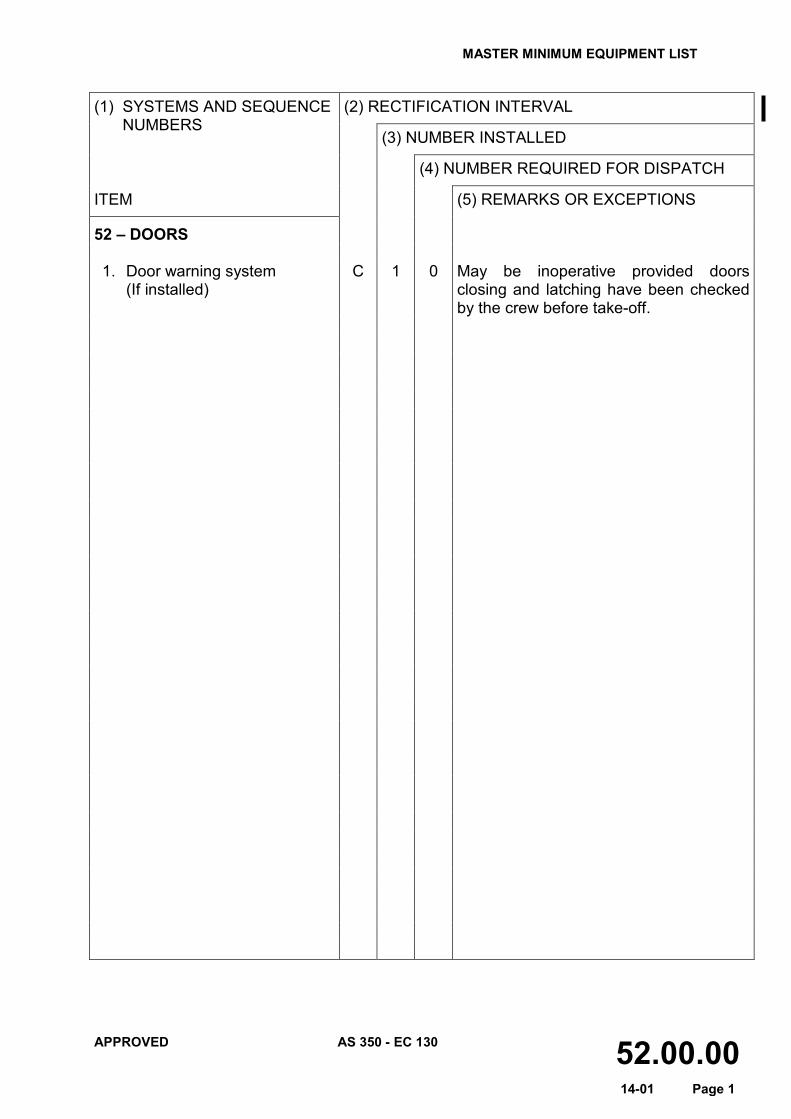
52 – DOORS 1. Door warning system (If installed)
C 1 0 May be inoperative provided doors closing and latching have been checked by the crew before take-off.

MASTER MINIMUM EQUIPMENT LIST
APPROVED AS 350 - EC 130 62.00.00 14-01 Page 1
(1) SYSTEMS AND SEQUENCE NUMBERS
(2) RECTIFICATION INTERVAL
(3) NUMBER INSTALLED
(4) NUMBER REQUIRED FOR DISPATCH
ITEM (5) REMARKS OR EXCEPTIONS
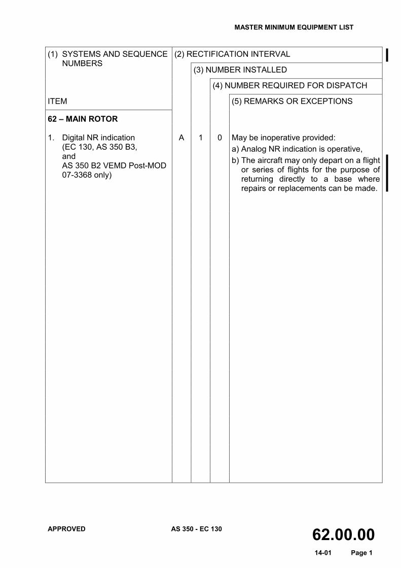
62 – MAIN ROTOR
1. Digital NR indication (EC 130, AS 350 B3, and AS 350 B2 VEMD Post-MOD 07-3368 only)
A 1 0 May be inoperative provided: a) Analog NR indication is operative, b) The aircraft may only depart on a flight
or series of flights for the purpose of returning directly to a base where repairs or replacements can be made.

MASTER MINIMUM EQUIPMENT LIST
APPROVED AS 350 - EC 130 63.00.00 14-01 Page 1
(1) SYSTEMS AND SEQUENCE NUMBERS
(2) RECTIFICATION INTERVAL
(3) NUMBER INSTALLED
(4) NUMBER REQUIRED FOR DISPATCH
ITEM (5) REMARKS OR EXCEPTIONS
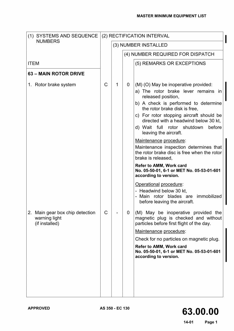
63 – MAIN ROTOR DRIVE 1. Rotor brake system
C 1 0 (M) (O) May be inoperative provided: a) The rotor brake lever remains in
released position, b) A check is performed to determine
the rotor brake disk is free, c) For rotor stopping aircraft should be
directed with a headwind below 30 kt, d) Wait full rotor shutdown before
leaving the aircraft. Maintenance procedure: Maintenance inspection determines that the rotor brake disc is free when the rotor brake is released, Refer to AMM, Work card No. 05-50-01, 6-1 or MET No. 05-53-01-601 according to version.
Operational procedure: - Headwind below 30 kt, - Main rotor blades are immobilized
before leaving the aircraft. 2. Main gear box chip detection
warning light (if installed)
C - 0 (M) May be inoperative provided the magnetic plug is checked and without particles before first flight of the day. Maintenance procedure: Check for no particles on magnetic plug. Refer to AMM, Work card No. 05-50-01, 6-1 or MET No. 05-53-01-601 according to version.

MASTER MINIMUM EQUIPMENT LIST
APPROVED AS 350 - EC 130 65.00.00 14-01 Page 1
(1) SYSTEMS AND SEQUENCE
NUMBERS
(2) RECTIFICATION INTERVAL
(3) NUMBER INSTALLED
(4) NUMBER REQUIRED FOR DISPATCH
ITEM (5) REMARKS OR EXCEPTIONS
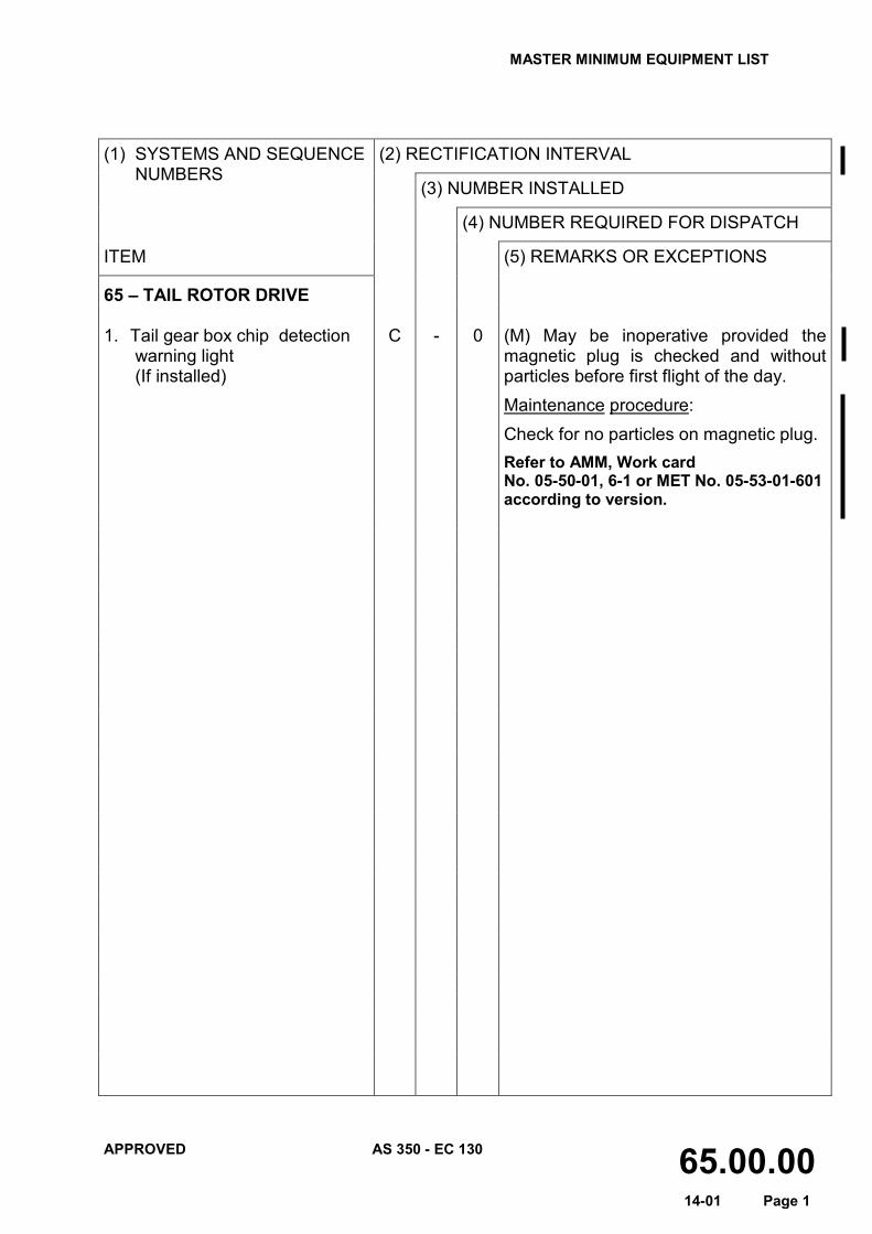
65 – TAIL ROTOR DRIVE 1. Tail gear box chip detection
warning light (If installed)
C - 0 (M) May be inoperative provided the magnetic plug is checked and without particles before first flight of the day. Maintenance procedure: Check for no particles on magnetic plug. Refer to AMM, Work card No. 05-50-01, 6-1 or MET No. 05-53-01-601 according to version.

MASTER MINIMUM EQUIPMENT LIST
APPROVED AS 350 - EC 130 71.00.00 14-01 Page 1
(1) SYSTEMS AND SEQUENCE NUMBERS
(2) RECTIFICATION INTERVAL
(3) NUMBER INSTALLED
(4) NUMBER REQUIRED FOR DISPATCH
ITEM (5) REMARKS OR EXCEPTIONS
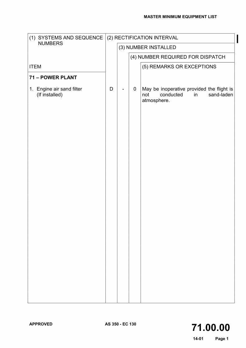
71 – POWER PLANT 1. Engine air sand filter
(If installed)
D - 0 May be inoperative provided the flight is not conducted in sand-laden atmosphere.

MASTER MINIMUM EQUIPMENT LIST
APPROVED AS 350 - EC 130 72.00.00 14-01 Page 1
(1) SYSTEMS AND SEQUENCE NUMBERS
(2) RECTIFICATION INTERVAL
(3) NUMBER INSTALLED
(4) NUMBER REQUIRED FOR DISPATCH
ITEM (5) REMARKS OR EXCEPTIONS
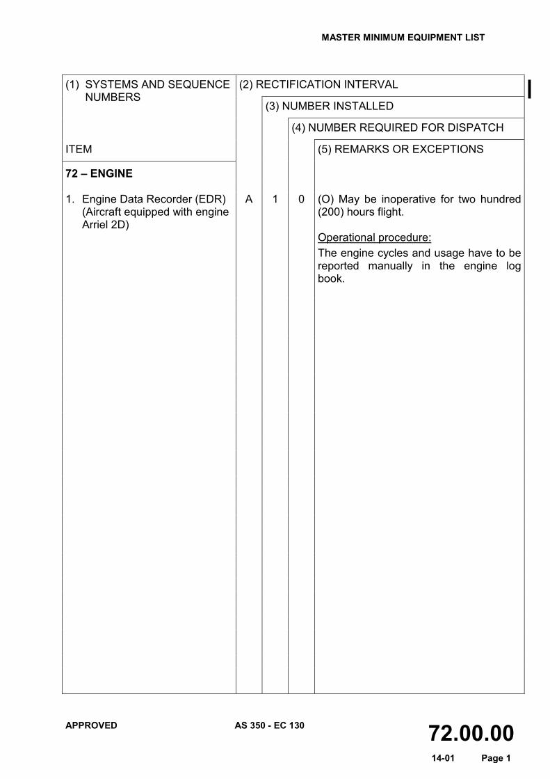
72 – ENGINE 1. Engine Data Recorder (EDR)
(Aircraft equipped with engine Arriel 2D)
A 1 0 (O) May be inoperative for two hundred (200) hours flight. Operational procedure: The engine cycles and usage have to be reported manually in the engine log book.

MASTER MINIMUM EQUIPMENT LIST
APPROVED AS 350 - EC 130 77.00.00 14-01 Page 1
(1) SYSTEMS AND SEQUENCE NUMBERS
(2) RECTIFICATION INTERVAL
(3) NUMBER INSTALLED
(4) NUMBER REQUIRED FOR DISPATCH
ITEM (5) REMARKS OR EXCEPTIONS
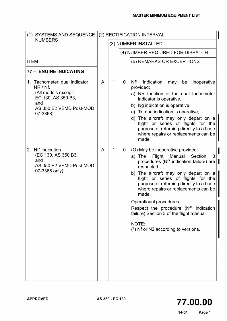
77 – ENGINE INDICATING 1. Tachometer, dual indicator
NR / Nf. (All models except: EC 130, AS 350 B3, and AS 350 B2 VEMD Post-MOD 07-3368)
A 1 0 Nf* indication may be inoperative provided: a) NR function of the dual tachometer
indicator is operative, b) Ng indication is operative, c) Torque indication is operative, d) The aircraft may only depart on a
flight or series of flights for the purpose of returning directly to a base where repairs or replacements can be made.
2. Nf* indication
(EC 130, AS 350 B3, and AS 350 B2 VEMD Post-MOD 07-3368 only)
A 1 0 (O) May be inoperative provided: a) The Flight Manual Section 3
procedures (Nf* indication failure) are respected,
b) The aircraft may only depart on a flight or series of flights for the purpose of returning directly to a base where repairs or replacements can be made.
Operational procedures: Respect the procedure (Nf* indication failure) Section 3 of the flight manual.
NOTE: (*) Nf or N2 according to versions.
Recommended