183
MEDER electronic
www.meder.com
DESCRIPTION
The RM05-4A-S-4/2 and RM05-2A2B-S-4/2 are low-profile 4 input / 2 output Relay Mod-ules with an FR-4 substrate and rugged ther-moset epoxy overmold. Capable of switching beyond 3 GHz with <40ps rise times, this Re-lay Module switches into the billions of opera-tions. High temperature solder terminations allow BGA reflow temperatures up to 220oC.
FEATURES
• FR-4/thermoset molded package• Leadless SMT design eliminates skewing and
coplanarity issues• Minimum path length for RF • <40ps rise times for switching fast pulses• Standard with BGA• Low profile• Internal magnetic shielding• Gold plated traces for high conductivity signal path• Insulation resistance typically 1014 ohms
APPLICATIONS
• Test and Measurement• Telecommunications• High frequency applications
DIMENSIONSAll dimensions in mm [inch]
unspecified tolerances +/- 0.1 mm
POST REFLOW HEIGHT
RM SeriesRF Reed Relay Module
4 input / 2 output

184
MEDER electronic
www.meder.com
RF Reed Relay Module 4 input / 2 output
ORDER INFORMATION
Part Number Example
RM05-4A-S-4/2
05 is the nominal voltage4A is the number and form of contacts S is the solder ball4/2 is 4 input to 2 output
RM Series
PAD LAYOUT (Top view) PAD DESIGNATION (Top view)
SHEMATIC (Top view)
Series NominalVoltage
ContactForm
Solder Balls Input Output
RM - 05 - 4A S - 4/ 2
4A-S-4/2 2A2B-S-4/2

185
MEDER electronic
www.meder.com
COIL DATA
RELAY DATA
RM Series
ContactForm
SwitchModel
CoilVoltage
CoilResistance
Pull-inVoltage
Drop-out Voltage
Nominal Coil Power
All Data at 20 °C *
VDC Ω VDC VDC mW
Min. Max. Min. Typ. Max. Max. Min. Typ.
4A2A2B
80 166.5 185 203.5 3.75 0.5 135
* The pull-in / drop-out voltage and coil resistance change at the rate of 0,4 % / °C.
ModuleCharacteristics Min. Typ Max. Units
Insertion Loss Input / Output TBD dB
Voltage standing Wave Ratio VSWR Input / Output TBD
Isolation Input / Output TBD dB
Rise Time Potential changeInput / Output TBD psec
Characteristics Impedance Input / Output TBD Ω
RF Reed Relay Module 4 input / 2 output
186
MEDER electronic
www.meder.com
RF Reed Relay Module 4 input / 2 output
RM Series
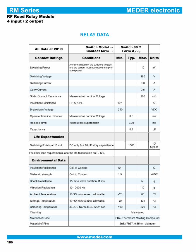
RELAY DATA
All Data at 20° CSwitch Model →Contact form →
Switch 80 /1 Form A / dry
Contact Ratings Conditions Min. Typ. Max. Units
Switching PowerAny combination of the switching voltage and the current must not exceed the given rated power.
10 W
Switching Voltage 180 V
Switching Current 0.3 A
Carry Current 0.5 A
Static Contact Resistance Measured w/ nominal Voltage 200 mΩ
Insulation Resistance RH Ω 45% 1010 Ω
Breakdown Voltage 250 VDC
Operate Time incl. Bounce Measured w/ nominal Voltage 0.6 ms
Release Time Without coil suppression 0.05 ms
Capacitance 0.1 pF
Life Expectancies
Switching 5 Volts at 10 mA DC only & < 10 pF stray capacitance 1000106
Cycles
For other load requirements, see the life test section on P. 120.
Environmental Data
Insulation Resistance Coil to Contact 1011 Ω
Dielectric strength Coil to Contact 1.5 kVDC
Shock Resistance 1/2 sine wave duration 11 ms 50 g
Vibration Resistance 10 - 2000 Hz 10 g
Ambient Temperature 10 oC/ minute max. allowable -20 85 oC
Storage Temperature 10 oC/ minute max. allowable -35 125 oC
Soldering Temperature JEDEC Norm JESD22-A113A 190 220 oC
Cleaning fully sealed
Material of Case FR4, Thermoset Molding Compound
Material of Pins Sn63/Pb37, 0.65mm diameter

187
MEDER electronic
www.meder.com
DESCRIPTION
FEATURES
• FR-4/thermoset molded package• Leadless SMT design eliminates skewing and copla-
narity issues• Minimum path length for RF • <40ps rise times for switching fast pulses• Standard with BGA• Low profile• Internal magnetic shielding• Gold plated traces for high conductivity signal path• Insulation resistance typically 1014 ohms
The RM05-4A-S-4/4 and RM05-2A2B-S-4/4 are low-profile 4 input / 4 output Relay Modules with an FR-4 substrate and rugged thermose epoxy overmold. Capable of switching beyond 3 GHz with <40ps rise times, this Relay Module switches into the billions of operations. High temperature solder terminations allow BGA reflow temperatures up to 220oC.
APPLICATIONS
• Test and Measurement• Telecommunications• High frequency applications
DIMENSIONSAll dimensions in mm [inch]
unspecified tolerances +/- 0.1 mm
POST REFLOW HEIGHT
RM SerieRF Reed Relay Module
4 input / 4 output

188
MEDER electronic
www.meder.com
RF Reed Relay Module 4 input / 4 output
ORDER INFORMATION
Part Number Example
RM05-4A-S-4/4
05 is the nominal voltage4A is the # and form of contacts S is the solder ball4/4 is 4 input to 4 output
RM Series
SHEMATIC (Top view)
PAD DESIGNATION (Top view)PAD LAYOUT (Top view)
+ + + +
Series NominalVoltage
ContactForm
Solder Balls Input Output
RM - 05 - 4A S - 4/ 4
4A-S-4/4 2A2B-S-4/4
189
MEDER electronic
www.meder.com
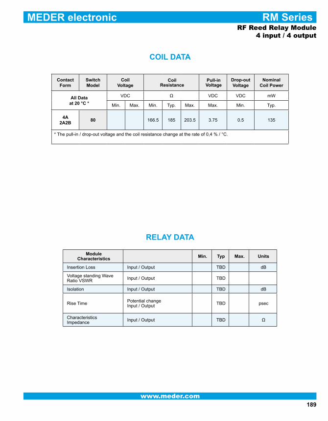
RELAY DATA
COIL DATA
RM Series
ContactForm
SwitchModel
CoilVoltage
CoilResistance
Pull-inVoltage
Drop-out Voltage
Nominal Coil Power
All Data at 20 °C *
VDC Ω VDC VDC mW
Min. Max. Min. Typ. Max. Max. Min. Typ.
4A2A2B
80 166.5 185 203.5 3.75 0.5 135
* The pull-in / drop-out voltage and the coil resistance change at the rate of 0,4 % / °C.
ModuleCharacteristics Min. Typ Max. Units
Insertion Loss Input / Output TBD dB
Voltage standing Wave Ratio VSWR Input / Output TBD
Isolation Input / Output TBD dB
Rise Time Potential changeInput / Output TBD psec
Characteristics Impedance Input / Output TBD Ω
RF Reed Relay Module 4 input / 4 output

190
MEDER electronic
www.meder.com
RF Reed Relay Module 4 input / 4 output
RELAY DATA
RM Series
All Data at 20° CSwitch Model → Contact form →
Switch 80/1Form A / dry
Contact Ratings Conditions Min. Typ. Max. Units
Switching PowerAny combination of the switching voltage and the current must not exceed the given rated power.
10 W
Switching Voltage 180 V
Switching Current 0.3 A
Carry Current 0.5 A
Static Contact Resistance Measured w/ nominal Voltage 200 mΩ
Insulation Resistance RH Ω 45% 1010 Ω
Breakdown Voltage 250 VDC
Operate Time incl. Bounce Measured w/ nominal Voltage 0.6 ms
Release Time Without coil suppression 0.05 ms
Capacitance 0.1 pF
Life Expectancies
Switching 5 Volts at 10 mA DC only & < 10 pF stray capacitance 1000 108
Cycles
For other load requirements, see the life test section on P. 120.
Environmental Data
Insulation Resistance Coil to Contact 1011 Ω
Dielectric strength Coil to Contact 1.5 kVDC
Shock Resistance 1/2 sine wave duration 11 ms 50 g
Vibration Resistance 10 - 2000 Hz 10 g
Ambient Temperature 10 oC/ minute max. allowable -20 85 oC
Storage Temperature 10 oC/ minute max. allowable -35 125 oC
Soldering Temperature JEDEC Norm JESD22-A113A 190 220 oC
Cleaning fully sealed
Material of Case FR4, Thermoset Molding Compound
Material of Pins Sn63/Pb37, 0.025” diameter

191
MEDER electronic
www.meder.com
The RM05-6AS-4/1 is a low-profile 4 input / 1 output Relay Module with an FR-4 substrate and rugged thermoset epoxy overmold. Ca-pable of switching beyond 3 GHz with <40ps rise times, this Relay Module switches into the billions of operations. High temperature solder terminations allow BGA reflow tem-peratures up to 220oC.
DESCRIPTION
APPLICATIONS
• Test and Measurement• Telecommunications• High frequency applications
FEATURES
• FR-4/thermoset molded package• Leadless SMT design eliminates skewing and
coplanarity issues• Minimum path length for RF • <40ps rise times for switching fast pulses• Standard with BGA• Low profile• Internal magnetic shielding• Gold plated traces for high conductivity signal
path
• Insulation resistance typically 1014 ohms
DIMENSIONS All dimensions in mm [inch]
unspecified tolerances +/- 0.1 mm
POST REFLOW HEIGHT
RM SeriesRF Reed Relay Module
4 input / 1 output

192
MEDER electronic
www.meder.com
RM Series
SHEMATIC
Part Number Example
RM05 - 6AS - 4/1
05 is the nominal voltage6A is the # and form of contacts S is the solder ball4/1 is 4 input to 1 output
ORDER INFORMATION
(Top view)
PAD LAYOUT (Top view) PAD DESIGNATION (Top view)
A B C D E F
G H I J
9
8
7
6
5
4
3
2
1TOP VIEW
Series NominalVoltage
ContactForm
Solder Balls Input Output
RM - 05 - 6A S - 4/ 1
RF Reed Relay Module 4 input / 1 output

193
MEDER electronic
www.meder.com
RF Reed Relay Module 4 input / 1 output
RM Series
COIL DATA
RELAY DATA
ContactForm
SwitchModel
CoilVoltage
CoilResistance
Pull-inVoltage
Drop-out Voltage
Nominal Coil Power
All Data at 20 °C *
VDC Ω VDC VDC mW
Min. Max. Min. Typ. Max. Max. Min. Typ.
6A 80 166.5 185 203.5 3.75 0.5 135
* The pull-in / drop-out voltage and the coil resistance change at the rate of 0,4 % / °C.
ModuleCharacteristics Min. Typ Max. Units
Insertion Loss Input / Output TBD dB
Voltage standing Wave Ratio VSWR Input / Output TBD
Isolation Input / Output TBD dB
Rise Time Potential changeInput / Output TBD psec
Characteristics Impedance Input / Output TBD Ω

194
MEDER electronic
www.meder.com
RF Reed Relay Module 4 input / 1 output
RM Series
RELAY DATA
All Data at 20° CSwitch Model → Contact form →
Switch 80/1 Form A / dry
Contact Ratings Conditions Min. Typ. Max. Units
Switching PowerAny combination of the switching voltage and the current must not exceed the given rated power.
10 W
Switching Voltage DC or Peak AC 180 VDC
Switching Current DC or Peak AC 0.3 A
Carry Current DC or Peak AC 0.5 A
Static Contact Resistance Measured w/ nominal Voltage 200 mΩ
Insulation Resistance RH Ω 45% 1010 Ω
Breakdown Voltage 250 VDC
Operate Time incl. Bounce Measured w/ nominal Voltage 0.6 ms
Release Time Without coil suppression 0.05 ms
Capacitance 0.1 pF
Life Expectancies
Switching 5 Volts at 10 mA DC only & < 10 pF stray capacitance 1000108
Cycles
For other load requirements, see the life test section on P. 120.
Environmental Data
Insulation Resistance Coil to Contact 1011 Ω
Dielectric strength Coil to Contact 1.5 kVDC
Shock Resistance 1/2 sine wave duration 11 ms 50 g
Vibration Resistance 10 - 2000 Hz 10 g
Ambient Temperature 10 oC/ minute max. allowable -20 85 oC
Storage Temperature 10 oC/ minute max. allowable -35 125 oC
Soldering Temperature JEDEC Norm JESD22-A113A 190 220 oC
Cleaning fully sealed
Material of Case FR4, Thermoset Molding Compound
Material of Pins Sn63/Pb37, 0.025” diameter

195
MEDER electronic
www.meder.com
RM Series
DESCRIPTION
The RM05-8A is a complete Relay Module with one se-rial digital 8 bit input channel, to drive a double output matrix with 4 to 1 channel each. Insert the code for the out signals at serial Input 8. At each positive impulse (clock signal) at Input 4, the code will be proceeded and the already inserted code in the shift register shifted for-ward one step. At pin 2, the code (9 clock signals shifted) can be transferred to the next module to drive even more Relay Modules. Is programming finished, the code in the shift register can be transferred to the output drives with a positive impulse (clock signal) at Input 5, witch will ac-tivate the selected output switches.
APPLICATIONS
• Test and Measurement
• Telecommunications
• Reed Relay Module with integrated shift register, storage register and buffer
• Saves PCB space• Saves wiring costs • Saves assembly costs
FEATURES
DIMENSIONSAll dimensions in mm [inch]
unspecified tolerances +/- 0.1 mm
PAD LAYOUT
Reed Relay ModuleRM05-8A

196
MEDER electronic
www.meder.com
Reed Relay ModuleRM05-8A
RM Series
SHEMATIC
RELAY MODULE COIL DATA
Coil / RelayCharacteristics Condition at 20 oC Min. Typ Max. Units
Current consumption with each switched contact
at 5V operating voltage 9 10 11 mA
Nominal Voltage 4.75 5.0 5.25 VDC
Nominal power with each switched contact at 5V operating voltage 50 mW
Insulation Resistance Coil to Contact 1011 Ω
Dielectric StrengthCoil to Contact 1.5 kVDC

197
MEDER electronic
www.meder.com
RM Series
RELAY DATA
All Data at 20° CSwitch Model → Contact form →
Switch 80 Form A / dry
Contact Ratings Conditions Min. Typ. Max. Units
Switching PowerAny combination of the switching voltage and the current must not exceed the given rated power.
10 W
Switching Voltage DC or Peak AC 125 VDC
Switching Current DC or Peak AC 1.0 A
Carry Current DC or Peak AC 1.5 A
Static Contact Resistance Measured w/ nominal Voltage 100 mΩ
Insulation Resistance RH Ω 45% 1010 Ω
Breakdown Voltage 200 VDC
Operate Time incl. Bounce Measured w/ nominal Voltage 0.4 ms
Release Time Without coil suppression 0.1 ms
Capacitance 0.3 pF
Life Expectancies
Switching 5 Volts at 10 mA DC only & < 10 pF stray capacitance 1000108
Cycles
For other load requirements, see the life test section on P. 120.
Environmental Data 1011
Insulation Resistance Coil to Contact 1.5 Ω
Dielectric strength Coil to Contact 50 kVDC
Shock Resistance 1/2 sine wave duration 11 ms 30 g
Vibration Resistance 10 - 2000 Hz -20 40 g
Ambient Temperature 10 oC/ minute max. allowable -35 95 oC
Storage Temperature 10 oC/ minute max. allowable 260 oC
Soldering Temperature JEDEC Norm JESD22-A113A 190 260 oC
Cleaning fully sealed
Material of Case FR4, Thermoset Molding Compound
Material of Pins Sn63/Pb37, 0.65mm diameter
Reed Relay ModuleRM05-8A
Recommended

![172 FERC ¶ 61,047 · 172 FERC ¶ 61,047 . DEPARTMENT OF ENERGY . Federal Energy Regulatory Commission . 18 CFR Parts 37 and 38 [Docket Nos. RM05-5-029, RM05-5-030] Standards for](https://img.pdfslide.net/doc/110x75/600664bf18db3c455500a643/172-ferc-61047-172-ferc-61047-department-of-energy-federal-energy-regulatory.jpg)


![FEDERAL ENERGY REGULATORY COMMISSION [Docket No. RM05-22-000]](https://img.pdfslide.net/doc/110x75/61fb46802e268c58cd5c3e4a/federal-energy-regulatory-commission-docket-no-rm05-22-000.jpg)