DRAFT (26Sep06)
Minimum Performance Standards for Aircraft Engine and APU Compartment Fire Extinguishing Agents/Systems
DRAFT (26Sep06) 1 of 31
DRAFT (26Sep06)
Introduction A fire extinguishing system (“system”) is required for each engine nacelle and auxiliary power unit (APU) compartment for certain categories of civilian airplanes. To address these requirements, two considerations must be made. First, an applicant must satisfactorily store and deliver some form of fire extinguishing agent (“agent”) to the protected compartment. Second, an applicant must measure the quantity of the agent within the protected compartment over time during and following the agent injection event. The principal success of such a system is based upon the measured history of the agent distribution meeting or exceeding the minimum level of safety as required by the appropriate regulatory authority. The culmination of these two considerations represents approximately 50 years of knowledge and experience exchanged between regulatory authority and industry.
To preclude confusion regarding the use of the word “fuel” in this document, fuel is defined here as any substance that can combust in an unintended manner in an engine nacelle or APU compartment. Fuel, as commonly understood, is not defined in this document as the substance used for propulsion, although turbine fuel can be a fuel feeding an unintended fire in an engine nacelle or APU compartment. Further, since FAA regulations do not address combustible metal fires by the regulations cited, metals acting as a fuel, as defined here, are excluded from consideration.
For existing aircraft, the likely agent used in this application is a total flooding agent, Halon 1301. The type of fire extinguishment system used to deliver the halon is composed of at least one storage vessel holding the agent and some super-pressurizing nitrogen, release valving, plumbing fittings, distribution plumbing, and nozzling for injection into the protected compartment. Typically, during developmental and certification evaluations, a gas analyzer utilizing a pressure drop across an orifice, commonly referred to as a Statham- or Halonyzer-variant gas analyzer, is used to measure the distribution behavior of the halon inside the protected compartment.
The goal of this document is to provide a process for an applicant, or its designee(s), to determine some quantity of a replacement candidate (“candidate”) that can be used for fire extinguishment in place of Halon 1301. Explanatory descriptions potentially valuable to an entity using this process are included within the flow of the procedural documentation. The process requires a test fixture, a system to deliver conditioned Halon 1301, the ability to produce 2 different fire threats based on typical flammable fluids found in a nacelle or APU compartment, a system to deliver a conditioned candidate, and some means to measure the time-varying behavior of the agent during its delivery to and transport through the test fixture. The experience to develop this process is contained in a report titled “TBD ???”, of which this document is an appendix. The reader should know that at some point in the future, Halon 1301 will no longer be the state of the art. At that time, the state of the art, referred to within this document as the current level of safety, will be redefined.
DRAFT (26Sep06)
Knowledge and judgement regarding what is acceptable will always change. To account for this, the definition for a candidate within this process can span from a substance that may “drop-in” the hardware used to store the halon with little or no modification and use
2 of 31
DRAFT (26Sep06)
the existing gas analysis technique for quantification to something requiring completely new methods to aviation for storage, delivery, and/or quantification. However, this process is currently fit to the state of the art, the Halon 1301 system and Statham/Halonyzer analysis concepts. Provisions have been made to allow for variation, as needed.
An applicant must assess the applicability of this process to their own halon replacement efforts based on their own circumstances. There are two scenarios for replacing halon. One is for an existing airplane and the second for a new. Given an existing airplane, this process is the likely method to complete a replacement effort based on the economic considerations of fire testing with actual aircraft components versus a simulation model. For a new airplane, an applicant may elect to forego this process and directly engage the pertinent regulations since there is no existing halon baseline. However, an applicant in either scenario may capitalize on results from this process if information is already publicly available for a candidate that is desirable.
Any entity using this process must remain diligent during testing. Observations will be the most important aspect to assess whether a candidate will acceptably perform. Additionally, observations may lead to changes in current philosophy regarding fire protection for these applications.
A successful application of the process described herein, including the comparison of the performance of Halon 1301 with that of the candidate, will allow the definition of an equivalent level of safety in terms of the performance of the candidate. At that point, it will be possible to define or evaluate the equivalent level of safety without using Halon 1301 as the standard.
An applicant intending to use this process in a stand-alone approach to halon replacement is clearly advised to involve their certifying, regulatory authority at the earliest possible point in the program in order to prevent the loss of time and money associated with discrepancy related to opinions or experiences. Additionally, successfully completing this process does NOT satisfy the requirements for certification by the Federal Aviation Administration (FAA) or any other regulatory authority recognizing the use of this process. An applicant must also adequately address other issues that are not considered by this process for these applications.
Discussion U.S. Federal Airworthiness Regulations (FAR) 23.1195, 25.1195 are the regulations that require fire extinguishment systems for the engine nacelle and APU compartments in certain types of airplanes. In the case of general aviation airplanes, special conditions may exist requiring the applicant to provide fire extinguishment systems as well. Similar regulations are also included in the European Joint Airworthiness Requirements (JAR) 25 and the forthcoming European Aviation Safety Agency (EASA) Certification Specification (CS) 25, both applying to large airplanes.
The current fire extinguishing systems using Halon 1301 as the agent are deemed to satisfy these requirements if the system can produce concentrations of Halon 1301
DRAFT (26Sep06) 3 of 31
DRAFT (26Sep06)
specified in FAA Advisory Circular 20-100 (FAA AC 20-100). This AC reports the performance of Halon 1301 from historical testing including large-scale fire tests. The process described herein is intended for use in large-scale fire testing for the purpose of developing performance criteria for systems using candidates. The current level of safety (CLS), as recognized by the FAA, is that provided by a volumetric concentration of 6 % Halon 1301 throughout a protected fire zone for a duration of 0.5 second for a given agent discharge scenario.
One challenge for this process is to saliently represent a nacelle fire but not restrict the applicability of the outcomes to one particular nacelle. Additionally, the purpose to use an agent in a nacelle or APU fire extinguishment system is to extinguish the unintended fire threat. Therefore, this process was tuned to minimize any flame extinction mechanisms that are not related to an agent, based on the assumption that the agent is the main factor in flame extinction. Flame strain is the principal example of a minimized flame extinction mechanism. Agent injection is specified not to blow the fire out. If flame strain is intended as an important flame extinction mechanism as part of a candidate, this process will require modification. Appropriate planning must occur to account for this deviation and, at a minimum, would require involvement from the regulatory authority.
The process to demonstrate equivalence with the CLS is based on four test configurations. Each of these four configurations is intended to represent the pertinent factors found in a nacelle or APU fire. By varying parameters to achieve these four configurations, a spread of behavior can be observed.
One can readily reason that 4 points is a small sample of a potentially infinite array of possible solutions when considering the numbers of nacelles and APU compartments flying today. However, those involved in the work to develop this process believe this spread is adequate to challenge the CLS and provide a method to compare and ultimately quantify a candidate for the purpose of replacing the agent recognized as the CLS. If a candidate possessed a potential weakness entering into testing or observations were made during testing, the testing entity will be required to illustrate the deficiency and respond accordingly.
The four test configurations are each a unique combination of compartment ventilation and fire threat. Inherent to all are flame holder geometries, persistent ignition threats represented by electrical arc and/or hot surfaces, and the persistent presence of fuel during agent injection and transport through the test fixture.
An important aspect for this testing will be the maintained control of the experiment. The highest state of cleanliness within the test fixture must be maintained at all possible cost. Additionally, items like agent handling while servicing, and agent and fuel conditioning prior to test require consistent procedure and endpoint to effect reliable test behavior. Understanding the tolerances in cleanliness and conditioning and their impact on test outcome will likely be an evolving experience as testing progresses.
DRAFT (26Sep06)
The method of comparison between the CLS and a candidate is two-fold and based on results observed and measured at the flame front of the fire threat for the selected test configuration.
4 of 31
DRAFT (26Sep06)
The first part is based on an agent mass equivalence. Mass equivalence results from comparing the fire extinguishment behavior for the CLS in one test configuration and forcing the candidate to repeat that same performance. This performance is simply a duration observed between the times of flame extinction and reignition as an agent pulse moves through the test fixture while enduring persistent fuel flow and ignition threat(s). This duration is an effective indicator of agent performance and should demonstrate a direct relationship with varying quantities of agent discharged into a test fixture. As agent quantity increases, the duration the fire is extinguished increases. The relationship appears linear in the normal ranges of interest but eventually ceases at some low endpoint once a threshold mass of agent is crossed. In other words, if an amount of agent discharged into the test section does not extinguish a fire, there is no duration between flame extinguishment and reignition. Although not observed to date, and likely impractical, there is a theoretical point where there would be such a large quantity of agent released into a test fixture, the fire would be permanently extinguished. For this case, the duration is infinite.
The second part is based on the comparison of the measured distribution history of the candidate in the test fixture with the outcomes from the mass equivalence resulting in a calculated equivalent concentration. The equivalent concentration is based on reasoning that the mass of an agent, the duration the fire is extinguished, and the associated distribution history from the measurement equipment are all related. Considering the relationship validates the reasoning. If one quantity of agent were delivered in the test fixture that produced a given duration the fire was extinguished, it would also demonstrate one particular distribution history. Now increase the mass of the agent and challenge the same fire. A different duration the fire was extinguished would result, a larger duration, and a distribution history having a greater area under the associated curves would result. Since the complexities of initial flame and maintained extinction are not easily separated, one must assume a constant agent concentration is responsible for flame extinction. This duration of flame extinction can then be used in conjunction with a polynomial best-fit curve describing the distribution history at the flame front to determine an effective, or called here, an equivalent concentration.
The final outcome from this process for any given candidate would be the equivalent concentrations from the four test configurations and any noteworthy observations. The expected activities after completing such a project would then be to recommend the highest equivalent concentration as the goal for any certification effort, resolve any anomalous behaviors discovered during this testing, acceptably satisfy all other issues not addressed by this document, and finally, demonstrate all required goals are satisfied for the aircraft installation to the applicable regulatory authority.
Overview of the Test Procedure The process is composed of three groups of requirements. The first set describes what is expected of the candidate by the regulatory authority and industry before any candidate is considered for evaluation. The expectations of any future candidate must meet operational demands if it were to be considered for use. These operational demands are not directly related to fire extinguishment performance and will be evaluated elsewhere.
DRAFT (26Sep06) 5 of 31
DRAFT (26Sep06)
The second set describes the infrastructure required to effect comparative testing between agents. The infrastructure would require design, investigation, and optimization, typically requiring attention for a single period of time. Once these infrastructure issues are resolved, they will be taken as constant, but should be maintained and checked on some basis in a sensible manner to ensure continuity. The third set describes the comparative testing. The requirements describing the comparative testing will be repeatedly visited and should become quite familiar to any testing entity.
The process requires a test fixture, two ventilation regimes, 2 fire scenarios, the agent representing the CLS, the candidate, a method to quantify both the agent and candidate within the test fixture, and to perform some mathematical calculations using the time-varying quantitative histories of the candidate found to be mass equivalent. The following requirements relate to the infrastructure and must be fulfilled prior to beginning any comparative testing between the CLS and a candidate.
The test fixture will be of a minimum size, cross section, and volume. Within the test fixture, the testing entity must establish 2 representative, ventilation regimes. For each of these regimes, a reliable agent distribution must be established that meets the intent of the CLS as measured and indicated by appropriate analysis equipment.
Two fire scenarios must be designed within the test fixture so that they demonstrate adequate combustion intensity. Both scenarios will be based on diffusion combustion of fuels representative of the engine nacelle and APU compartments. One scenario will be based on a fuel spray and the other on a residual pool. The spray scenario will have persistent ignition threats represented by an electrical arc and a hot surface. The residual pool will have a persistent ignition threat represented by an electrical arc. Fuels feeding the spray at any given point during testing will be turbine fuel, lubricant or hydraulic fluid. Turbine fuel will be the basis for the residual pool.
By pairing one ventilation regime with one fire threat, a single test configuration is specified. Hence, for two fire threats and two ventilation regimes, four test configurations are created.
The mass equivalence portion of the process requires that the agent representing the CLS be released multiple times in a given test configuration. The duration that the fire is extinguished from each test is averaged together. This is called the benchmark. Successful mass equivalence, in its simplest form, is the endpoint of a trial-and-error approach used to find the mass of a candidate that can produce the average duration or some larger value for the CLS using the same number of repeated tests in the same configuration.
For each ventilation regime, the mass equivalence produced for a spray fire threat must be based on the fuel producing the most severe fire threat. In one of the spray fire configurations, the candidate must be evaluated against all 3 fuels to ensure no negative interactions with the remaining fuels.
After completing the mass equivalence, the quantity of the candidate within the test fixture that succeeded must be quantified with appropriate measurement equipment. The
DRAFT (26Sep06) 6 of 31
DRAFT (26Sep06)
equivalent concentration is calculated by solving the best-fit polynomial representing the candidate distribution history for the mass equivalent in order to reproduce the average duration determined for the candidate during the mass equivalence evaluation.
This cycle should be repeated for the four test configurations. Each test configuration must be run to completion, unless preliminary efforts indicate failure. Each test configuration will require setting a benchmark, a mass equivalence search with conclusion, and quantification of conditions satisfying mass equivalence. The time to complete a test configuration should be minimized, yet balanced by the time required for quality work. Testing behaviors will demonstrate sensitivities to ambient conditions.
DRAFT (26Sep06) 7 of 31
DRAFT (26Sep06)
References The following references form the basis to understand the current Halon 1301 performance criteria for aircraft engine and APU fire extinguishing systems (refs 1 - 7). The balance are included to enhance a reader’s knowledge regarding other discussions which occur within this document.
1. Federal Aviation Administration Advisory Circular AC 20-100, 1977.”General Guidelines for Measuring Fire Extinguishing Agent Concentrations in Powerplant Compartments.”
2. Middlesworth, C.M., 1952, "Aircraft Fire Extinguishment, Part I - A Study of Factors Influencing Extinguishing System Design," Technical Development Report No. 184, Civil Aeronautics Administration Technical Development and Evaluation Center, Indianapolis, IN.
3. Hughes, C.A., 1953, "Aircraft Fire Extinguishment, Part II - The Effect of Air Flow on Extinguishing Requirements of a Jet Power-Plant Fire Zone," Technical Development Report No. 205, Civil Aeronautics Administration Technical Development and Evaluation Center, Indianapolis, IN.
4. New, J.D., and Middlesworth, C.M., 1953, "Aircraft Fire Extinguishment, Part III - An Instrument for Evaluating Extinguishing Systems," Technical Development Report No. 206, Civil Aeronautics Administration Technical Development and Evaluation Center, Indianapolis, IN.
5. Hughes, C.A., and Middlesworth, C.M., 1954, "Aircraft Fire Extinguishment, Part IV - Evaluation of a Bromochloromethane Fire Extinguishing System for the XB-45 Airplane," Technical Development Report No. 240, Civil Aeronautics Administration Technical Development and Evaluation Center, Indianapolis, IN.
6. Hansberry, H.L., 1956, "Aircraft Fire Extinguishment, Part V - Preliminary Report on High-Rate-Discharge Fire Extinguishing Systems for Aircraft Power Plants," Technical Development Report No. 260, Civil Aeronautics Administration Technical Development and Evaluation Center, Indianapolis, IN.
7. Klueg, E.P., and Demaree, J.E., 1969, "An Investigation of In-Flight Fire Protection with a Turbofan Powerplant Installation," Report No. NA-69-26, Federal Aviation Administration, National Aviation Facilities Experimental Center, Atlantic City, NJ.
8. Bennett, J.M., Caggianelli, G.M., Kolleck, M.L., and Wheeler, J.A., 1997a, "Halon Replacement for Aviation, Aircraft Engine Nacelle Application Phase I - Operational Parameters Study," Report No. WL-TR-95-3077, Wright Laboratories and Booz, Allen, and Hamilton, Incorporated, Wright Patterson Air Force Base, OH.
DRAFT (26Sep06) 8 of 31
DRAFT (26Sep06)
9. Bennett, J.M., Caggianelli, G.M., Kolleck, M.L., and Wheeler, J.A., 1997b, "Halon Replacement for Aviation, Aircraft Engine Nacelle Application Phase II - Operational Comparison of Selected Extinguishants," Report No. WL-TR-97-3076, Wright Laboratories and Booz, Allen, and Hamilton, Incorporated, Wright Patterson Air Force Base, OH.
10. Bennett, J.M., Bennett, M.V., 1999, "Aircraft Engine/APU Fire Extinguishing System Design Model (HFC-125)," Report No. AFRL-VA-WP-TR-1999-3068, Air Force Research Laboratory and Booz, Allen, and Hamilton, Incorporated, Wright Patterson Air Force Base, OH.
11. Myronuk, D.J., Oct 1980, “Dynamic, Hot Surface Ignition of Aircraft Fuels and Hydraulics Fluids,” AFAPL-TR-79-2095, Aero Propulsion Laboratory, USAF Wright Aeronautical Laboratories, Wright Patterson Air Force Base, OH.
12. Johnson A.M., Grenich, A.F., “Vulnerability Methodology and Protective Measures for Aircraft Fire and Explosion Hazards / Fire Detection, Fire Extinguishment, and Surface Ignition Studies,” AFWAL-TR-85-2060, Volume II, pt. I, USAF Wright Aeronautical Laboratories, Wright Patterson Air Force Base, OH.
13. Hamins, A., et al, 1995, “Suppression of Engine Nacelle Fires,” Special Publication 890, Volume 2, National Institute of Standards and Technology, Gaithersburg, MD.
14. Zabetakis, M.G., “Flammability Characteristics of Combustible Gases and Vapors,” Bureau of Mines bulletin 627, US Department of the Interior, Bureau of Mines, Washington, D.C.
DRAFT (26Sep06) 9 of 31
DRAFT (26Sep06)
Procedure 1. Requirements for candidates that are not addressed by this document Any candidate considered for use in an engine nacelle or APU fire extinguishing system must adequately meet the following requirements. These requirements are evaluated elsewhere.
1.A. Environmental Characteristics. 1.A.1. The environmental characteristics of a candidate must comply with
international laws and agreements. 1.A.2. The candidate should be listed in the US Environmental Protection Agency’s
Significant New Alternatives Policy program. Since engine nacelle and APU compartments are not normally occupied spaces, candidates identified for use in such spaces are permissible.
1.B. Health and Safety. The fire extinguishing agent/system for an engine compartment or an APU configuration must satisfy the following safety and health requirements.
1.B.1. Health and Safety in Handling. 1.B.1.a. The candidate should be designed to minimize exposure of workers to
unsafe conditions during installation and normal maintenance of the system. 1.B.1.b. Safety features incorporated in the equipment and handling procedures for
any candidate that mitigate hazards to workers should be taken into account while assessing compliance with this provision.
1.B.2. Flight Safety. The use and operation of the candidate in the aircraft should not result in any additional hazard such as:
1.B.2.a. Malfunction of components critical for flight control necessary for continued safety of flight.
1.B.2.b. Damage to other critical components and areas within the compartment being protected, which would create a hazard either immediately or remain undetected and be a hazard after a passage of time.
1.B.2.c. Products resulting from the discharge of the neat candidate or decomposition by-products resulting from combustion exposure in these compartments must not be conveyed into spaces occupied by living things within the pressure vessel of the aircraft
1.B.2.d. Ignition sources in any area of the aircraft not designed for accommodating ignition sources
1.C. The candidate should be compatible with all materials of construction found in its storage and delivery hardware and the protected compartment in which it will be injected, whether neat or decomposed.
1.C.1. This applies to all definitely and potentially wetted boundaries of any test apparatus and any aircraft installation.
1.C.2. Decomposition products resulting from fire and extinguishment exposure are aggressive. This is not avoidable. However, post-incident evaluation and related cleaning or repair are the mechanisms used to thwart negative material compatibility outcomes.
1.D. The candidate must have an acceptable shelf-life while installed on the aircraft. 1.E. Acceptable Candidate Performance for the airplane operational envelope
DRAFT (26Sep06) 10 of 31
DRAFT (26Sep06)
1.E.1. The testing entity must know by reasonable evaluation that the candidate can demonstrate any future design point recommended as certification for all storage conditions that will be found on the associated airframe.
1.E.2. The applicant will be required to demonstrate adequate distribution at the thermal endpoints of the airplane’s operational envelope to the respective airworthiness authority.
1.E.3. This test procedure does not require hot- or cold-soaked for gaseous candidate testing. Accounting for the environment in the nacelle and reviewing literature to learn how flammable systems generally behave with respect to flammable limits and thermal energy illustrate the bases of this specification.
1.E.3.a. Peak agent inerting concentrations decrease with decreasing system temperature for flammable, gaseous, premixed systems.
1.E.3.a.1. Persistent hot surface areas in the presence of spilling liquid fuel may exist, thus producing an environment where air and fuel vapors may be mixing. This mixing would likely be turbulent. A measure related to this condition, although not identical, is the testing related to determine flammability limits, such as ASTM E-681 or E-918. Regardless, a system of air and fuel in a gaseous state is more hazardous (favoring combustion) than that of air and a liquid fuel that must change phase and diffuse.
1.E.3.a.2. Flammability envelopes produced for gaseous flammable systems incorporating various mixtures of an agent, fuel, and oxygen within explosion sphere clearly illustrate that peak inerting agent concentrations decrease with decreasing flammable system temperature.
1.E.3.a.3. The areas inside these flammability curves also decrease with decreasing temperature
1.E.3.a.4. Given two flammable systems, the colder of the two will require a lower inerting agent concentration
1.E.3.b. The environment at a cruise altitude is not consistent with the nacelle ambient environment. Citing the standard atmosphere, one will find at altitudes in the 30,000 ft range having ambient temperatures on the order of -40°F. The average operational environment within the nacelle will be on the order of 100°F or greater.
1.E.3.c. Consider the FAA process to demonstrate certification. A fire extinguisher bottle cold-soaked to -65°F is discharged into the fire zone. For success, the measurement history must indicate all points simultaneously achieve 6%v/v Halon 1301 for 0.5 second.
1.E.3.c.1. The cold-soaked bottle condition is related to the storage environment of the bottle outside the nacelle that is conditioned by exposure to the ambient environmental conditions.
1.E.3.c.2. The 6%v/v Halon 1301 can be traced back to flammability testing completed at room temperature.
1.E.3.d. Conclusions. 1.E.3.d.1. The cold-soaked condition is related to the agent storage environment,
not the fire extinguishment demand. This is an agent delivery issue. This issue that does not require fire testing to establish behavior.
DRAFT (26Sep06) 11 of 31
DRAFT (26Sep06)
1.E.3.d.2. The fire extinguishment demand is similar to the nacelle environment. This test process is intended to establish the fire extinguishment demand.
2. Infrastructure The items contained within this section must be completed then proven reliable and repeatable prior to attempting any equivalence testing.
2.A. Test Fixture 2.A.1. Structure
2.A.1.a. The materials of construction for current nacelles consist of either metal or composite fiber construction. Either material is permissible for use providing the structural design of a nacelle fire simulator includes allowances for :
2.A.1.a.1. the stresses of repeated fire testing without altering 2.A.1.a.2. environmental behaviors which would interfere with interpreting
equivalence testing results 2.A.1.a.3. reasonable access to the interior for cleaning, maintenance, and
alteration or repair 2.A.1.a.4. the ability to observe and record the internal environmental behaviors 2.A.1.a.5. accepting :
2.A.1.a.5.1. A ventilation flow. 2.A.1.a.5.2. Two fire scenarios plus their related workings. 2.A.1.a.5.3. The injection hardware for the fire extinguishing system. 2.A.1.a.5.4. All required telemetry to record environmental behavior.
2.A.1.b. The engine compartment (nacelle) simulator should have an annular fire zone having a minimum volume of 65 cubic feet and a minimum annular cross section of 5.5 square feet, both before reductions due to clutter. The inner cylinder in this configuration will represent the engine case. The test section must be equipped to allow a real time visual observation of the fire.
2.A.1.c. Additional Commentary 2.A.1.c.1. The size of the zone was selected on the basis of the range of fire
zone sizes of actual aircraft installations and considerations for a practical simulator where physical parameters can be properly simulated and controlled.
2.A.1.c.2. A separate simulator for APU compartments is not necessary because experience from testing by the U. S. Air Force has shown that the requirements developed for the engine compartment provide equal or higher level of safety for the APU compartment.
2.A.1.c.3. The FAATC simulator sits on a 4000 ft^2 concrete floor. It is composed of 90 feet of air flow pathway. The test section has an approximate volume of 100 ft^3 with an annular cross section of 9.4 ft^2. Its core is a 0.25 inch x 24 inch outside diameter steel tube surrounded by a steel skeleton holding 5 pairs of steel doors that are hinged at the top and close to form a concentric shell around the core. The up- and down-stream duct transitions are fabricated from 16 gage, galvanized, sheet metal. This fixture has withstood some 5 years of active fire testing using appropriate fire hardening, maintenance, and repair as required. The access to the
DRAFT (26Sep06) 12 of 31
DRAFT (26Sep06)
interior of the test section’s full length is possible after every test. As of the writing of this process, the fixture is being taken off-line for heavy repair due to large-scale assault from the repeated, internal exposures to fire and chemical over these years of testing.
2.A.2. Telemetry 2.A.2.a. The behaviors occurring in the test fixture must be captured to record the
environmental behavior. These behaviors will be used to observe and learn about what is occurring within the environment of the test fixture, compare consistency or change between tests, and track change over the life time of the fixture.
2.A.2.b. The data collection and telemetry package should include traditional methods using devices such as thermocouples and pressure transducers. Non-traditional assemblies can also be used to enhance understanding. Additionally, the complete record of any test also requires a visual record of the fire threat’s behavior that includes a time reference.
2.A.2.c. There is no minimum specification for the data collection hardware. However, it must be collected reliably at rates sufficient to capture salient data from the testing environment for review and use.
2.A.2.d. There is no minimum count for each type of transducer used. This judgement is left to the discretion of the testing entity. If applicable, including the regulatory authority regarding the type, number, and location of the transducers in the telemetry package is advisable.
2.A.2.e. Additional commentary. 2.A.2.e.1. The video record will be the principal means to compare the
performances of a candidate and the current state of the art. A camera appropriately located to view the fire scenario, having its image recorded, is required. In this visual record, there must also be some form of time record superimposed in the visual record.
2.A.2.e.2. The duration the fire was extinguished then reignited is typically too quick to interpret from thermocouple response, even if fine-wire, due to the sensor’s thermal inertia. Comparison of various recording methods (thermocouple, video, photodiode) from FAATC records clearly demonstrated superiority laid with visual means to determine the duration of fire extinction. Since the human interpretation from video tape was the initial means to assess the duration, it remains the choice method so links to historical data can be maintained.
2.A.2.e.3. The video records created at the FAATC reside on standard VHS tape as recorded by a surveillance camera. The camera image passes through a video time-date generator, having a stop watch capable of 0.01 second, before being recorded to tape. The limitation of the store-bought video cassette recorder permits a viewer to observe test behavior one video frame at a time, which is roughly a duration of 0.02-0.04 second between frames.
2.A.2.e.4. There are two pieces of data collection hardware used at the FAATC. The larger system is capable of 64 channels and a smaller capable of 8. The smaller unit is dedicated to capture the pressure transducer and photodiode
DRAFT (26Sep06) 13 of 31
DRAFT (26Sep06)
histories. Events for these devices require sampling rates of 50 Hz or greater. A single test is controlled by the larger data collection system since it has the ability to control relay functions. Its sampling rate is 1 Hz and is inadequate to capture rapid events, however, the thermal behavior of the test environment is easily retained.
2.A.2.e.5. Telemetry used at the FAATC includes : 2.A.2.e.5.1. Fine-wire (28-32 AWG), exposed bead, thermocouples sense air
temperatures inside the test section at different station locations to assess the air temperature. The bulk ventilation temperature is calculated at one of these station locations (not exposed to fire). Some of these thermocouples were located inside the volume of flame resulting from the fire threat.
2.A.2.e.5.2. Probe thermocouples measured agent temperature and air temperatures where the thermocouples were persistently bathed in flame.
2.A.2.e.5.3. No thermocouples were corrected for radiation heat transfer error (analytically or physically).
2.A.2.e.5.4. A hot wire anemometer measured the center-line airflow of the inlet duct for the nacelle fire simulator so the air mass flow passing through the fixture could be recorded.
2.A.2.e.5.5. Pressure transducers were used to measure agent storage pressure in the fire extinguisher assembly, static pressure in the test section, and the simulator exhaust duct; the static pressure transducers were added later in the project.
2.A.2.e.5.6. Four photodiodes were added later in the project to record flame behaviors in regions of the test fixture downstream from the spray fire scenario and outside the view field of the video camera.
2.B. Establishing the Operational Environment of the Test Fixture 2.B.1. Ventilation Regime
2.B.1.a. At least two internal (ventilation) airflow rates should be selected, one each from the following two ranges.
2.B.1.a.1. (a) High 2.2 - 3.0 lbm/sec. 2.B.1.a.2. (b) Low 0.2 – 1.0 lbm/sec.
2.B.1.b. At least two (ventilation) air temperatures of 100 and 250°F or greater should be used.
2.B.1.c. Additional Commentary 2.B.1.c.1. “high ventilation” corresponds to about 57 air changes per minute for
the fire zone having 65 cubic feet volume and 5.5 square feet cross sectional area. For significantly different volume and cross section, the airflow rates should be adjusted appropriately. These flow rates cover the significant range of air flows in modern engine installations. This information is based on a US Air Force survey. Note that ventilation airflow is a commonly used term for airflow through the engine compartment.
2.B.1.c.2. Air temperature as low as -40 oF could exist in some cases under extremely cold atmospheric conditions at high altitudes. However, under these conditions an engine fire threat is extremely unlikely due to low power
DRAFT (26Sep06) 14 of 31
DRAFT (26Sep06)
demand from the engine, cold fuel and relatively cooler surfaces in the fire zone. In addition, these conditions could delay the detection of a small fire which could result in an increase in air temperature. These are adequate reasons to conclude that this fire threat could be easily overcome by a system designed for larger fire threats which are likely when the air and surface temperatures are higher. Therefore, it is not necessary to simulate air temperatures below the ambient conditions in the test facility. However, for consistency between tests conducted during different ambient conditions, a controlled air temperature is preferred. Therefore 100 oF is selected to represent the lower end of the temperature range.
2.B.1.c.3. FAATC test fixture. 2.B.1.c.3.1. Perforated baffles that choke the inlet duct to the supply blower
that feeds the simulator are used to control the amount of air passing through the fixture. A more restrictive baffle is used to provide the lower air flow rate, a less restrictive baffle for the higher. Recent measurements and somewhat more complex calculations based on flows through the inlet duct indicate the low ventilation rate is around 1.0 lbm/s and the high ventilation rate around 2.7 lbm/s. Variation is observed to be +/- 0.1 lbm/s for both instances.
2.B.1.c.3.2. The air heating is completed by electrical resistance heaters upstream of the test section to attain the 100°F design point. The same heaters are used in conjunction with an oil burner to attain the second design point. The oil burner is ducted into roughly the first half of internal volume of the core. Its effluent is exhausted out pipes downstream from the fire scenarios. The surface of the core is known to reach 700°F at one location away from the fire scenarios during this type of operation.
2.B.2. Agent Storage, Delivery, and Measurement. 2.B.2.a. The comments in this section apply to all agents, whether the current level
of safety (CLS) or a candidate, that are stored as a liquid/vapor mixture or a liquid, which, upon discharge, are expected to evaporate into a gas to extinguish a fire. Any novel concept brought forth as a candidate will require assessment at the time of inception. Some of these comments will apply to a new concept, some will not. Including the regulatory authority during the test project planning for any novel concept is advisable.
2.B.2.b. Any agent must be safely and appropriately stored in some containment that is acting as a fire extinguisher vessel. This vessel can range from a true aircraft fire extinguisher bottle to a uniquely designed assembly. The containment will serve multiple purposes for each test.
2.B.2.b.1. Agent conditioning during test preparation. 2.B.2.b.2. Agent discharge into the test fixture during a test.
2.B.2.c. The containment vessel must have appropriate thermal and pressure ratings for the work expected.
2.B.2.d. There must be an ability to consistently observe the agent’s temperature during conditioning in preparation for a test.
DRAFT (26Sep06) 15 of 31
DRAFT (26Sep06)
2.B.2.e. The vessel must have a releasing mechanism that can reliably actuate to discharge the agent into the test fixture.
2.B.2.f. Establishing the current level of safety (CLS). 2.B.2.f.1. The agent defining the CLS will be gaseous and non-particulate for
some years to come. With this condition, the Statham-/Halonyzer-variant analyzers will continue to be the principle method of measuring the current level of safety. However, no one can predict the future. Therefore, this section contains comments that are relevant to any agent plus comments pertaining to a specific agent class (gas, solid aerosol or liquid aerosol).
2.B.2.f.2. There is a subtle difference between what the FARs require of an agent and how it is evaluated in a protected compartment. Assumptions are built in to any evaluation that will extrapolate a collection of sampled points scattered throughout the volume into a full representation of the agent’s presence in the compartment. This process is obviously focused on the practicality of agent evaluation, but must not misrepresent the intent of the FARs.
2.B.2.f.2.1. The principles required in the FARs indicate that the agent when deployed through a suitable system must be capable of extinguishing any probable fires in the aircraft engine designated fire zone or in the APU compartment for which the system is intended. A real fire could be large, engulfing most of the protected fire zone in flames or it could be small, localized fire depending on the source and quantity of fuel and other conditions such as the air flow. The requirement for the fire extinguishing system is to defeat the fire anywhere in the zone including the entire zone.
2.B.2.f.2.2. For the purpose of evaluating the agents, it is necessary to : 2.B.2.f.2.2.a. create a representative fire in a representative fire zone and
show that the candidate can be distributed effectively in that zone to extinguish the fire
2.B.2.f.2.2.b. determine the quantity at the location of the fire that resulted in successful extinguishment. To do so does not require having a fire everywhere in the compartment because if it can be shown that a specific real system can produce the required agent distribution throughout the compartment which satisfies the condition determined in the fire test then it ensures that a fire will be defeated throughout the compartment.
2.B.2.f.3. Demonstrating the adequacy of the CLS. When the agent is delivered to the test section, it must demonstrate the CLS. Recall a testing entity is not attempting to protect a fire zone for this test process. The intent is to establish parity with the CLS by evaluating a candidate with a reliable test and evaluation procedure
2.B.2.f.3.1. Gaseous agents. 2.B.2.f.3.1.a. Meeting the intent of the CLS means the sampling points must
simultaneously equal or exceed the volumetric concentration for the given duration. In the case of Halon 1301, the distribution history should achieve 6 % volumetric concentration of Halon 1301 for 0.5
DRAFT (26Sep06) 16 of 31
DRAFT (26Sep06)
second. Given this process requires at least 2 ventilation regimes, there will be at least 2 distinct configurations for the agent containment and injection so that the CLS can be demonstrated.
2.B.2.f.3.1.b. How adequacy is defined, in part, is a function of the volume bounded by a gas analyzer’s sampling points within the test section.
2.B.2.f.3.1.c. The geometric locations for the sampling points must be chosen carefully.
2.B.2.f.3.1.d. They should present a picture of the full annular cross section as well some longitudinal distance in the test section. AC 20-100 can be used for guidance in selecting the locations.
2.B.2.f.3.1.e. The choice of location must consider the flame front position for each fire scenario. Although the CLS will be defined by these sampling points, the candidate will also be evaluated at the flame front of each fire scenario using this same installation.
2.B.2.f.3.2. Solid aerosol agents. (reserved) 2.B.2.f.3.3. Liquid aerosol agents. (reserved)
2.B.2.f.4. Agent Storage and Delivery 2.B.2.f.4.1. The specifications in the section are purposely vague. No one can
predict the future. However, an applicant must meet the intent of this section, yet fairly represent the candidate being considered.
2.B.2.f.4.2. All agent injection plumbing must be capable of the thermal and pressure insults typical of agent injection (discharge) events. It must be secured to prevent damage to persons or structure during normal testing in the event of failure.
2.B.2.f.4.3. The agent should be conditioned to a storage temperature of 100°F for each test.
2.B.2.f.4.3.a. It should be stored consistent with industry practice, if such guidance exists.
2.B.2.f.4.3.b. This requirement may be unnecessary in the case of solid aerosol agents (i.e. inert gas generators)
2.B.2.f.4.4. Injection plumbing in the test section must minimize, if not eliminate, any flame extinguishment mechanisms which are not related to the agent. Injection nozzles should be located some distance away from the fire scenarios. They should not be pointed at the fire scenarios. The plumbing should direct the agent injection jet(s) perpendicular to or upstream into the ventilation stream.
2.B.2.f.4.5. There is no constraint on the duration of the agent injection. It is one factor of many that has an effect on how much mass is required to produce a certain concentration behavior.
2.B.2.g. Additional Commentary 2.B.2.g.1. Any agent acting as the CLS or as a candidate will require
quantification. Subsections are included to enhance further understanding the intent of this issue. A particular replacement agent could be in a solid, liquid or gaseous phase when interacting with the fire and its effectiveness might be dependent on both the state and the quantity of the agent. For
DRAFT (26Sep06) 17 of 31
DRAFT (26Sep06)
example, the particle size of a solid agent or the droplet size of a liquid agent could influence its performance. This process is meant to apply to any type of agent including liquid and solid. However, acceptable methods to specify concentration of solid or liquid agents have not been identified for aircraft applications. Therefore, the generic term “quantity” may be used here. For halocarbon agents, which are in gaseous form as they interact with the fire, the practice of specifying extinguishing concentration is acceptable. In the following sections, whenever the term concentration is used for this purpose, it is not meant to exclude the applicability of this process to other types of agents. It will be necessary to develop suitable methods for specifying the performance of solid or liquid agents prior to their evaluation tests. Any parameters critical to these new methods such as line sizes, line temperatures, nozzle configurations etc. must be controlled during tests. If the effectiveness of the agent is highly dependent upon a certain parameter, it should be investigated through additional testing and documented.
2.B.2.g.1.1. Quantifying Gaseous Agents. 2.B.2.g.1.1.a. It has become the normal practice to specify the performance
of a gaseous agent (such as Halon 1301 after a discharge) in terms of the volumetric concentration required to extinguish the fire.
2.B.2.g.1.1.b. Volumetric concentration of the agent should be recorded. 2.B.2.g.1.1.c. If it is not practical to record the agent concentration in a fire
test, back to back tests must be conducted. That is, tests must be conducted with and without the fire with the same fire simulation parameters. The agent would be discharged in both tests in identical manners. The concentration measurement in the test without the fire would correspond to the extinguishing performance in the test with the fire.
2.B.2.g.1.2. Quantifying Solid Agents. (reserved) 2.B.2.g.1.3. Quantifying Liquid Agents. (reserved)
2.B.2.g.2. The fire extinguisher at the FAATC. 2.B.2.g.2.1. The unit was provided to the FAA by the USAF. 2.B.2.g.2.2. The unit is a uniquely designed/fabricated assembly composed of
a modified, steel, 3000 psi, 5 gallon hydraulic accumulator, strapped by circular band heaters with electric controls, and capped by a 1.25” pneumatically-controlled ball valve to discharge the agent. The agent containment can be varied both in volume and temperature. The firex valve is actuated by electrical signal from the large data acquisition system.
2.B.2.g.2.3. The agent storage temperature is indicated by a probe thermocouple in the center of the discharge throat cross section at the bottom of the assembly just above the discharge valve. A pressure transducer records the pressure inside the containment in the discharge throat from a tap 90° from the thermocouple tap.
2.B.2.g.2.4. FAATC Halon 1301 injection plumbing.
DRAFT (26Sep06) 18 of 31
DRAFT (26Sep06)
2.B.2.g.2.4.a. Bent stainless steel tubes of varying diameter from 0.5 – 1.25” and wall thickness connect the agent containment to the interior of the test section.
2.B.2.g.2.4.b. No injection plumbing points at the fire. For high ventilation, injection occurs approximately 6 feet forward of the fire scenarios and at low, approximately 5 feet forward. The high ventilation nozzles inject agent forward roughly 45° above horizontal and into the ventilation stream at 12:00 and radially each at roughly 4:00 and 8:00 bouncing agent off the core and shell. Low ventilation nozzles inject agent at roughly 1:00 and 11:00. At each clock position the injection is perpendicular to the ventilation; 2 opposed jets, one directed at 12:00 on the shell and a third jet perpendicularly outward into the shell.
2.B.2.g.3. Agent quantification at the FAATC 2.B.2.g.3.1. A modified, Pacific Scientific HTL Halonyzer II is used to
capture the behaviors of gaseous agents within the test fixture. 2.B.2.g.3.1.a. A varying 0-5 direct current voltage is used to indicate the
gaseous concentration. 2.B.2.g.3.1.b. Twelve sample points are captured for each distribution test. 2.B.2.g.3.1.c. The analyzer is maintained on-site.
2.B.2.g.3.2. Gas analyzer sample probe installation at the FAATC. 2.B.2.g.3.2.a. The 12 sample points are separated into 3 rings of 4 points. 2.B.2.g.3.2.b. Each point is positioned at the midpoint between any
structural surfaces inside the test section proximal to the sampling point. The idea is to capture the free stream concentration behavior.
2.B.2.g.3.2.c. The forward and aft rings are separated by 2 feet and have the same clock positions of 12:00, 3:00, 6:00, and 9:00 for the sampling points.
2.B.2.g.3.2.d. The mid ring is positioned at the flame front, is equidistant between the fore and aft rings, and has a pseudo-120° separation scheme. The fourth point on the ring is a redundant sample point used at the flame front. Clock positions are chosen based on the fire scenario; a pool fire sees 1:30, 5:45, 6:15, and 10:30, and the spray fire sees 12:15, 4:30, 7:30, and 11:45.
2.B.2.g.3.2.e. The tubing used for sampling is a 12 foot length of 0.125 inch outside diameter soft copper refrigeration line. The tube dimensions were chosen to minimize the internal volume to enhance the analyzer response yet access the internal sampling locations. The material was chosen to resist the insult from high ventilation air flow. The circular planes of the orifices for each tube end are all parallel to the longitudinal axis of the test section.
2.B.3. Fire threats within the test fixture. 2.B.3.a. The fire intensity must be adequate or misleading outcome may result.
The severity of the fire in these scenarios should be sufficient to maintain flaming combustion when exposed to half the quantity of the current level of safety (CLS) for the required duration and the most severe fuel.
DRAFT (26Sep06) 19 of 31
DRAFT (26Sep06)
2.B.3.a.1. For a gaseous agent this is a reasonably simple exercise. As an example, if using Halon 1301 as the CLS, a 3% v/v Halon 1301 concentration profile for 0.5 second is the challenge. This is nothing more than using the same system used to deliver 6%v/v Halon 1301 except reducing by one half the storage volume and agent mass.
2.B.3.a.2. If the CLS is defined in the future by a non-gaseous agent, then this specification will require review.
2.B.3.b. The fuels evaluated must include those expected in the protected compartment; typically a turbine fuel, a lubricant, and a hydraulic fluid.
2.B.3.c. There should be structural features in both fire scenarios to provide flame attachment for the resultant fires such that flaming combustion is self sustaining once an initiating ignition source is removed.
2.B.3.d. The fire should burn for some consistent, prescribed preburn duration during each test to permit heating the local structure prior to discharging the fire extinguishing agent. Temperature histories will be key to understanding what rates of change are occurring. The test length should be chosen to permit the fixture to attain a near steady-state condition when agent is discharged. Preburn durations of 60-90 seconds are typically reasonable.
2.B.3.e. The fuel temperature should begin at a temperature of 150°F for both fire scenarios. Fuel flow path should be temperature controlled throughout the test fixture to ensure this control remains reasonably intact during the length of a test. Fuel flow temperature should be measured as close to the fire as possible.
2.B.3.f. Large batches of fuel stock should be acquired before embarking on equivalence testing to ensure that batching changes will not confound test results. A prime example for this concern is the use of 2 separate bulk sources of turbine fuel within one test project. If noticeable changes in test result are observed, a change in fuel flash point between the batches should be checked and ruled out as a cause for the discrepancy.
2.B.3.g. Ignition sources for the fire scenarios. 2.B.3.g.1. Ignition sources used to ignite test fires are referred to as initiating
ignition sources and may be any concept that can reliably start a test fire. If any initiating ignition source foreign to a nacelle is used, careful control should be maintained to ensure it does not interfere with test results.
2.B.3.g.2. Ignition sources used that provide a persistent reignition threat in the fire scenario after extinguishment by the agent are referred to as secondary ignition sources and must be related to concepts that exist in a nacelle or APU compartment.
2.B.3.g.3. Electrical arc and/or hot surface threats are acceptable secondary ignition sources due to their presence in actual aircraft engine nacelle and APU fire zones.
2.B.3.h. The geometric position and operational condition of the following should be consistently and rigorously maintained during any test project.
2.B.3.h.1. All initiating ignition sources. 2.B.3.h.2. All secondary ignition sources. 2.B.3.h.3. Any nozzle(s) delivering fuel to the test fires.
DRAFT (26Sep06) 20 of 31
DRAFT (26Sep06)
2.B.3.h.4. The vessel containing the pool fire. 2.B.3.i. Fire tests should be run to compare the combustion behavior of the various
fuel types without discharging agent to establish their operational behaviors. 2.B.3.j. Describing the fire threats.
2.B.3.j.1. The test fixture must provide simulation of a flaring fire (leaking fuel stream on fire, also called a spray fire) and a residual fire (baffle stabilized pan fire due to ignition of accumulated fuel in some part of the fire zone).
2.B.3.j.2. Spray fire scenario 2.B.3.j.2.1. A fuel flow rate of 0.1 to 1 gpm. The fuel flow rate should remain
constant for the length of testing during any test project. The choice of fuel flow may be an arbitrary one. It does not necessarily need to reflect an actual aircraft. What it does need to do is provide an adequate fire intensity that is described under citation 2.B.3.a.
2.B.3.j.2.2. The fuel flow must remain on before and after the discharge of the agent to ensure that the extinguishment duration will end.
2.B.3.j.2.3. The secondary ignition sources must be located in the fuel spray pattern to ensure efficient operation. These sources must contain at least one reliable, persistent, ignition threat from both groups :
2.B.3.j.2.3.a. electrical arc 2.B.3.j.2.3.b. hot surface
2.B.3.j.2.4. The spray fire scenario at varying times in a test project will be based on turbine fuel, a lubricant or a hydraulic fluid. The fire threat intensity relating the 3 fuels must be understood as related to ventilation regime and ranked from least to most severe.
2.B.3.j.3. Pool fire scenario 2.B.3.j.3.1. The one secondary ignition source is an electrical arc. 2.B.3.j.3.2. The pool fire is based on turbine fuel (Jet-A, JP-8). 2.B.3.j.3.3. Experimentation will be important to determine the reignition
characteristics of this fire scenario. 2.B.3.j.3.3.a. The recirculation zone that sets up over the fuel surface
behind a flame attaching structure should vary with free stream flow speed. Ensure that the recirculation aerodynamics do not provide an opportunity to confuse the interpretation of test results.
2.B.3.j.3.3.b. Exposed fuel surface for combustion is not specified. It can either be selected by expected pool sizes that may be found in an actual airplane or it can be sized to the confines of the test fixture.
2.B.3.j.3.3.c. Observing flame spread across the fuel surface to understand different behaviors and then permit optimizing the reignition event prior to any equivalence testing is recommended.
2.B.3.k. Additional commentary 2.B.3.k.1. A fire in an engine or an APU compartment is probable when a fuel
and air mixture come in contact with an ignition source and result in a sustainable combustion reaction. Airflow through an engine or APU compartment is normal and a fuel source is possible due to leakage of aviation engine fuel, hydraulic fluid or engine oil or due to a failure
DRAFT (26Sep06) 21 of 31
DRAFT (26Sep06)
expelling these fuels. The ignition source could be any surface at a temperature above the hot surface ignition temperature for the fuel in the compartment. Electrical arcs or frictional sparks as a result of a failure may also provide potential ignition sources. Ignition can also occur if the fuel enters an environment in which rapid heating causes it to exceed its autoignition temperature. Three typical combustible fluids for the fire must be considered: aviation engine fuel, hydraulic fluid and engine oil.
2.B.3.k.2. In an aircraft installation, when the fire alarm is received an action is initiated resulting in a sequence of events. The engine fuel supply is shut off first. Hot air and electrical sources may also be shut off before activation of the fire extinguishing system. If the alarm occurs during the climb phase of the flight, more than a minute may elapse between the alarm and the discharge of the agent. In other cases, this elapsed time may be shorter than a minute.
2.B.3.k.3. Proper operation of the fuel delivery system for a simulator, including nozzles, should be checked to assure that the fire size and intensity are reproducible in tests with similar conditions. A measurement of heat flux density to characterize the fire is not necessary. Undue importance could be attached to this parameter as a means to determine reproducibility of fires while the measurement itself could depend on a variety of different factors.
2.B.3.k.4. The fire scenario intensity is established purely by experimentation. Combinations of ventilation rate, flame holder geometry, fuel spray flow rate or pool geometry, electrical arc type and position, and hot surface type and position are all factors which require investigation so that the collective scenario can produce a sufficiently intense fire consistent with citation 2.B.3.a.
2.B.3.k.5. Ranking the spray fire intensities in the FAATC nacelle fire simulator.
2.B.3.k.5.1. Establishing the relationship was completed by simply recording the thermal energy behaviors of the fire by thermocouple.
2.B.3.k.5.2. Intensity ranking proved easily at high ventilation. The largest areas under the thermocouple traces indicated which fuel was most severe for the evaluated conditions. The duration the fire was extinguished given a constant agent and mass corroborated the thermal observations. Turbine fuel is the most severe.
2.B.3.k.5.3. Intensity ranking at low ventilation was confounding. Early thermal histories recorded for oil produced larger areas under the thermocouple traces instead of the turbine fuel. As a contradiction, during work with Novec 1230 in 2006, the duration the fire was extinguished for an oil spray fire was longer than that for turbine fuel. Halon 1301 repeated the contradiction. Work in 2003 with HFC-125 did not indicate this contradiction. During the fuel verification testing, which will be described later, the contradiction was caught and permitted finding the mass equivalent based on the most severe fire threat condition (turbine fuel). As
DRAFT (26Sep06) 22 of 31
DRAFT (26Sep06)
of this writing, reasons explaining why this change has occurred remain unclear.
2.B.3.k.6. FAATC spray fire scenario 2.B.3.k.6.1. The fuel line supplying the 2 fuel nozzles is completely contained
within a water jacket for 95% of its length inside and outside of the test section. Reasonable control for the fuel temperature is maintained during testing.
2.B.3.k.6.2. Flame attachment provision is effected by discharging the fuel sprays from the 2 nozzles whose orifices are each approximately 1 inch above a 2 inch tall x 0.25 thick rib fastened to the core surface. The nozzle spray plumes are directed downstream along the core in the same direction as the ventilation flow. Upon attaining the initial ignition, if the arc is turned off, the fire continues as its initial intensity. The spray fire demonstrates repeatable and acceptable intensity at a total flow rate of 0.25 gpm.
2.B.3.k.6.3. The electrical arc is maintained in the right-most fuel spray cone and left continually operating for the full length of the test.
2.B.3.k.6.3.a. The tips are cleaned after every test by wiping off debris and residue with a cloth wetted by a non-aggressive cleaner.
2.B.3.k.6.3.b. The tips are maintained at a consistent gap in a consistent location.
2.B.3.k.6.3.c. The tips are stainless steel electrodes which can be found at any company capable of repairing most home-heating, oil burning appliances.
2.B.3.k.6.3.d. The arc is provided by stepping up 120 VAC, 60 Hz electricity to 10,000 VAC using a transformer. A suitable transformer can be taken from any home-heating oil burning appliance.
2.B.3.k.6.3.e. The electrical arc used in the FAATC facility is based on locally available hardware. A testing entity can use resources readily available to them ranging from store-bought material from local stores to parts scavenged from aircraft. Regardless of approach, note that the arc must be shown to reliably ignite the fuel spray and be persistently present during any test.
2.B.3.k.6.4. The hot surface is an array of tubes. 2.B.3.k.6.4.a. A tube array is located roughly 15 inches downstream from
the fuel nozzles. It is a collection of four 0.5 inch diameter x 34 inch long x 0.035 inch wall stainless steel tubes. Cutting a cross section through one finds the centers of the four circles making the corners of a rhombus. The upper pair of tubes straddles the top of the rear tube in the lower pair. They are bent to a radius which is concentric with the core. They are held approximately 2.5 inches above the core surface. The four tubes are bound tightly together with safety wire and worm-gear clamps and are wired to a pair of rigid core mounting bracket. A probe thermocouple is bound in between the tubes and the bead sits near 12:00.
DRAFT (26Sep06) 23 of 31
DRAFT (26Sep06)
2.B.3.k.6.4.b. Typical temperatures observed from this thermocouple range between 1400-1800°F. The range of temperature is related to the structural alteration of the tube array during repeated heating and cooling cycles resulting from testing. The tip is exposed to direct flame (higher temperature) or hidden by tube (lower temperature). In the testing between 2003 – 2006, there is only one observed instance that the tube array alteration affected the behavior of the test outcomes. A problem was discovered then resolved, and normal test behavior subsequently resumed.
2.B.3.k.6.4.c. The tube array is heated by the preburn duration of the fire threat and functions as a hot surface ignition threat reliably. It has a finite life span of 10 tests, as its properties begin to change somewhere beyond this number which affects the reliability of the reignition delay.
2.B.3.k.7. FAATC pool fire scenario 2.B.3.k.7.1. The pool of fuel is 0.5 inch deep x 10.8 wide by 20.5 long. The
long dimension is parallel to the central axis of the test fixture and ventilation stream. The pool sits inside a steel pan assembly that has water passages in its bottom to cool the fuel and assembly to a reasonable extent during each fire test. The forward lip of the pool provides a 1 inch tall baffle for flame attachment purposes.
2.B.3.k.7.2. There is no active effort to maintain a constant fuel depth during a test.
2.B.3.k.7.3. The electrical arc is found on the longitudinal center-line 17 inches aft of the forward lip for high ventilation and 10 inches aft for low. The actual arc gap is located at the fuel surface because testing indicated the reliability of reignition was an abrupt function of height above the fuel’s surface. The electrical arc is maintained on for the full length of each test and is cleaned afterwards. A description of the electrical system producing the arc and the cleaning process is provided in citation 2.B.3.k.6.3.
2.B.3.k.7.4. The preburn duration is 90 seconds.
DRAFT (26Sep06) 24 of 31
DRAFT (26Sep06)
3. Testing Procedure 3.A. By attaining this part of the process, the testing entity has established a reliable
test fixture, understands its 2 fire scenarios, and can produce the CLS. The test fixture can also accommodate the injection of the candidate for which the project was designed.
3.B. Important Definitions. 3.B.1. Reignition Time Delay (RTD). This is the difference in time between the 2
events of fire extinction and reignition related to an agent discharge in the test fixture. The duration of time is the direct result of an agent passing through a fire scenario with active combustion in the presence of a ventilation flow, persistent ignition source(s), and the persistent presence of fuel. This duration will likely be assessed from some form of visual record. i.e. the fire extinguished at 4:23.06 indicated by a superimposed stop watch in the video record and then reignited at 4:24.37. The RTD = 24.37-23.06 = 1.31 seconds.
3.B.2. “Transformed” concentration history. This definition applies explicitly to the quantification of gaseous agents. It is a mathematical curve that results from a simple arithmetic exercise where one works through a concentration history and determines the time a single curve equals a certain concentration. i.e. for a given concentration curve, it hits 6%v/v during the concentration increase at 45.2 seconds and 45.7 seconds on the concentration decrease; 45.7 - 45.2 = 0.5. The related transformed curve would have one point at (0.5, 6). Repeating this concept for a reasonable range of concentration values at an appropriate resolution will permit producing a sufficient number of points to generate a polynomial best-fit curve. The object is not to skew data, but faithfully represent it. Consider this as a mechanism to average together multiple concentration histories.
3.B.3. Mass equivalence. 3.B.3.a. This is the part of the equivalence process which establishes parity for fire
extinction performance. This equivalence is based on testing where the average RTD of a number of tests for the CLS relates to the same for a candidate. This is the initial part of the equivalence demonstration.
3.B.3.b. Mass equivalence is obtained in one of 2 ways. 3.B.3.b.1. Single-point. A quantity of the candidate is tested which produces an
average RTD, for the same number of repeated tests as the CLS, that is the same or larger. Consider this a direct reflection of safety. The candidate’s average RTD must be the same or larger to preserve the intent of the CLS. If the candidate’s average RTD was less than that of the CLS, the intent of the CLS is not maintained.
3.B.3.b.2. Multiple-point. 3.B.3.b.2.1. RTD and agent mass share a direct relationship. 3.B.3.b.2.2. Using this behavior permits forming a relationship that can be
used to predict candidate behavior relating to the point defined by the CLS’ benchmark. For a multiple-point solution, two possibilities exist; that of interpolation and extrapolation. The optimal choice would be to surround, or bracket, the CLS behavior forcing an interpolation condition.
DRAFT (26Sep06) 25 of 31
DRAFT (26Sep06)
3.B.3.b.2.3. During the initial search for a mass equivalent solution, this behavior can be used to indicate where expected success for a candidate will be found.
3.B.3.b.3. For either solution of the mass equivalence, the average RTD(s) will be used in calculations found in the definition for the concentration equivalence.
3.B.3.b.4. Examples : 3.B.3.b.4.1. Single-point solution. An initial guess of 8.2 lb of candidate
“SCD” produces an average RTD of 2.0 sec which is larger than the average RTD of the CLS by 0.2 second. Each average RTD is based on 5 repeated tests.
3.B.3.b.4.2. Multiple-point solution. An initial guess of 8.2 lb of candidate “SCD” produces an average RTD of 3.0 seconds which is larger than the average RTD of the CLS by 1.2 seconds. A second guess of 7.0 lb of candidate “SCD” produces an average RTD of 1.1 seconds. This is 0.7 second less than the CLS. Each average RTD is based on 5 repeated tests.
3.B.3.b.4.3. Note that these examples are for conceptual illustration. The chosen values do not necessarily indicate actual behaviors.
3.B.4. Concentration equivalence. 3.B.4.a. This equivalence is a calculation resulting from the use of a best-fit
polynomial that describes a transformed representation of the candidate’s quantitative history (i.e. gas concentration history). The polynomial is solved to reproduce the average RTD from the mass equivalent solution for the candidate. This is the outcome from one test configuration.
3.B.4.b. The quantity of a candidate and how it distributes in the test fixture share a direct relationship.
3.B.4.c. Determining the equivalent concentration is dependent upon the mass equivalent solution.
3.B.4.c.1. Mass equivalence, single-point solution. Solve the polynomial best-fit curve for the average RTD of the candidate.
3.B.4.c.2. Mass equivalence, multiple-point solution. 3.B.4.c.2.1. Solve the polynomial best-fit curve for the average RTD of each
candidate mass. The solution for each mass will produce one ordered pair consisting of an equivalent concentration and an average RTD.
3.B.4.c.2.2. Use the data pairs and solve for an equivalent concentration at the CLS benchmark.
3.B.4.c.3. Examples. 3.B.4.c.3.1. Concentration equivalence for a single-point mass equivalence. A
3rd order best-fit polynomial, representing a transformed concentration history measured by analyzer, representing 8.2 lb of candidate “SCD”, is A1x^3-A2x^2+A3x-b=c (x-axis is gas concentration, y-axis is time). By guessing concentrations, the equivalent concentration of 7.5 %v/v is found to reproduce the average RTD of 2.0 sec for candidate “SCD”.
3.B.4.c.3.2. Concentration equivalence for a multiple-point mass equivalence. Two points (x = equivalent concentration, y = average RTD) are (9.5, 3.0)
DRAFT (26Sep06) 26 of 31
DRAFT (26Sep06)
for 8.2 lb of candidate “SCD” and (11.0, 1.1) for 7.0 lb, in accordance with 3.A.4.d.1. The CLS benchmark was 1.8 seconds. Since the average RTDs of the candidate bracket the benchmark, a linear interpolation would be used to calculate the equivalent concentration of 10.4 %v/v.
3.B.4.c.3.3. Note that these examples are for conceptual illustration. The chosen values do not necessarily indicate actual behaviors.
3.C. Detailed Procedure for one test cycle. 3.C.1. Mass Equivalence.
3.C.1.a. Set up the test fixture for the chosen ventilation regime, fire scenario, and current level of safety (CLS).
3.C.1.a.1. If working with a spray fire, the fuel used as the basis for mass equivalence must be the most severe of the 3.
3.C.1.a.2. Ensure the CLS is not directly discharging at the fire. 3.C.1.a.3. Ensure all air, fuel, and agent or candidate conditioning parameters
are attained prior to running each test. 3.C.1.b. Begin testing with the CLS to establish the benchmark for the candidate.
3.C.1.b.1. Challenge the test configuration with the CLS configuration appropriate for the ventilation regime.
3.C.1.b.2. A minimum of 5 repeated tests must be completed. Repeated tests at the FAATC have had ranges less than 2 seconds and standard deviations less than 0.6.
3.C.1.b.3. After completing 5 repeated tests, calculate the average RTD that will define the benchmark. Calculate and record the sample standard deviation also.
3.C.1.c. Begin testing with the candidate to establish a mass equivalence. 3.C.1.c.1. The fire scenario in the test fixture is fixed at the condition being
tested. Change nothing. 3.C.1.c.2. Candidate injection should not be directed at the fire. 3.C.1.c.3. Using at least pairs of repeated tests at a given candidate mass,
determine the average RTDs to assess behavior in order to find the desired mass equivalence.
3.C.1.c.4. For 5 repeated tests, the average RTD must equal or be larger than that for the CLS to establish a successful mass equivalence.
3.C.1.d. Upon attaining mass equivalence, if working with the spray fire scenario, begin the fuel verification testing with the successful mass equivalent.
3.C.1.d.1. Challenge the mass equivalent with the other 2 fuels. 3.C.1.d.2. Perform 3 tests for each fuel and record each RTD. 3.C.1.d.3. Calculate the average RTDs and standard deviations for each fuel. 3.C.1.d.4. Compare the average RTDs between the fuels. If the average RTD for
the initial, most severe fuel remains smaller or equal to the other fuels’ average RTDs, the test behavior is acceptable.
3.C.1.d.5. If the average RTD for the initial, most severe fuel ends up being larger than one of the other fuels’ average RTDs, fuel verification has failed. If fuel verification fails :
3.C.1.d.5.1. Stop further testing in this configuration.
DRAFT (26Sep06) 27 of 31
DRAFT (26Sep06)
3.C.1.d.5.2. Retract candidate injection system. 3.C.1.d.5.3. Install CLS injection system. 3.C.1.d.5.4. Begin test sequence again with the new “most severe” fuel as the
basis for comparison. Establish the CLS benchmark. 3.C.1.d.5.5. Upon completing CLS testing, change back to the candidate
plumbing. 3.C.1.d.5.6. Find the mass equivalent for the candidate. 3.C.1.d.5.7. Fuel verification does not require repeating if all 3 fuels were
challenged. However, if not, the candidate must be evaluated against each of the 3 fuels. Prior test history within a single test configuration can be used as fair data representation.
3.C.1.e. After successfully finding the mass equivalent and passing fuel verification, stop fire testing.
3.C.2. Concentration Equivalence. 3.C.2.a. Install quantity measuring equipment. 3.C.2.b. Perform 3 repeated tests to record the time-varying quantitative histories
for each candidate mass defining the mass equivalence. If a multiple-point mass equivalence, 6 tests total are required; a single-point mass equivalence requires 3.
3.C.2.c. Stop testing and begin data reduction and analytical manipulations. The analysis should be performed according to the pertinent subsection as indicated by the agent class of the candidate.
3.C.2.c.1. Gaseous agents. 3.C.2.c.1.1. For each equivalent mass of the candidate, extract the 2
concentration histories for the flame front of the fire scenario from each of the 3 data files. This will produce six traces for evaluation.
3.C.2.c.1.2. Transform each from exponential growth/decay into a a collection of points describing the duration the concentration history was at a given concentration. Typically, determine the duration of each trace at 0.25%v/v increments from 1 - 9%v/v or 0.5%v/v increments from 1-18%v/v. Keep concentration on the x-axis and the time on the y-axis.
3.C.2.c.1.3. Establish a best-fit polynomial describing the scatter plot of the entire collection of points from the 6 traces. Typically, a 3rd order polynomial is adequate.
3.C.2.c.1.4. Start guessing concentrations and solve the best-fit polynomial by finding the concentration that reproduces the average RTD of the candidate from the mass equivalence iteration. The guessed concentration producing the average RTD is the equivalent concentration.
3.C.2.c.2. Solid aerosol agents. (reserved) 3.C.2.c.3. Liquid aerosol agents. (reserved)
3.C.3. If all four test configurations have not been completed, continue this cycle of testing until all four are completed.
3.C.4. Conclusion from Testing. 3.C.4.a. Collect all information and summarize in a report. 3.C.4.b. The information contained in the report at a minimum should include :
DRAFT (26Sep06) 28 of 31
DRAFT (26Sep06)
3.C.4.b.1. an overview of the structural and data collection aspects of the test fixture
3.C.4.b.2. the conditions in which it operated during the equivalence testing 3.C.4.b.3. equivalent mass information and behaviors 3.C.4.b.4. equivalent concentration information and calculations 3.C.4.b.5. references to and potential explanations regarding any anomalous
behaviors observed. 3.C.5. Additional Commentary.
3.C.5.a. If keeping the injection duration reasonably similar, when the agent mass is increased, the RTD should increase. If this trend is not true, there is an underlying reason that will likely confuse the outcomes of testing. One example producing a confused outcome may be natural instability of the ventilation being randomly altered by the agent injection flow.
3.C.5.b. Solving the problem of finding the mass equivalence is an art-like capability based on experience. During testing at the FAATC, early work was completed by single-point solution then changed to multiple-point solution. The testing with HFC-125 and CF3I in 2003 was completed by trying to find a single-point solutions, but staying within a close tolerance above the CLS’ average RTD. This can require numerous tests and, more so debilitating, configuration changes to maintain agent storage conditions (20-25 tests/configuration + time lost due to multiple configuration changes). By 2006 while working with Novec 1230, the single-point solution had nearly vanished. A multiple-point solution in the form of a bracket surrounding the CLS’ average RTD proved successful (10-15 tests/configuration, excluding investigations for anomalous behavior). In the case of high ventilation pool fire testing using Novec 1230, from benchmark to captured concentration history was on the order of 2 weeks. The time to complete the particular configuration was one of those rare instances when everything worked and behaved in desirable manners, for a change. Do not plan future activity on such rates of completion.
3.C.5.c. Fuel verification failed once during testing at the FAATC for the duration between 2003-2006 while evaluating HFC-125, CF3I, and Novec 1230.
3.C.5.d. A testing entity must attempt to minimize the margin of success for a candidate. One must recall the numbers coming from this effort will likely lead to certification. If an applicant carries too large a quantity on an aircraft due to excessive success from this process, that largess will translate to lost revenue over the life of the airframe. Unfortunately there is no guidance as to how much success is too much. Efforts at the FAATC have attempted to keep the average RTD for successful mass equivalence of a candidate larger than the CLS’ average RTD but within +1σ, where σ is calculated on the CLS data.
3.C.5.e. Although efforts at the FAATC have attempted to keep down the magnitude of success for a candidate, schedule or on-hand supplies restricting a test count may negatively impact the search for a precise answer to the equivalence problem. One concept rationalized to relieve this burden is the establishment of a multiple-point mass equivalence. This tool would require
DRAFT (26Sep06) 29 of 31
DRAFT (26Sep06)
performing a minimum 10 fire tests and 6 gas analyzer tests. Preferably, the candidate is quantified twice, in one instance the mass equivalent is successful and the second it is deficient. Six gas analyzer tests are run so each mass is quantified. Using the average RTDs and the quantitative histories, a pair of points each consisting of an average RTD and an equivalent concentration are created. The CLS benchmark fits between each average RTD for the candidate, and by having the pair of equivalent concentrations, a linear interpolation can be calculated. One caution though is the attempt to keep the 2 points reasonable close to the CLS’ benchmark. There is no guidance for what is reasonably close, so judgement will be required. In a worst case scenario, the two points may require an extrapolation condition. In an extrapolation condition, assessing all factors in the test project may be used to rationalize a viable outcome.
3.C.5.f. Data produced during testing at the FAATC was previously reviewed to determine an effective way to assess the progress of repeated fire tests towards mass equivalence. Obviously, time and money are most effective used if the least number of tests can be run to complete the four test configurations. The data from mass equivalence testing indicated better than 50% chance for success to attain mass equivalence if the cumulative RTD for the candidate remained between a tolerance described by the CLS’ benchmark +/- its sample standard deviation. A testing entity must understand this is not a guarantee, but guidance indicating an acceptable probability of success. As the repeated test count approaches five, the average RTD for the candidate should be tending to or above the CLS’ benchmark.
3.C.5.g. The sample standard deviation for each cluster of 5 repeated tests should be calculated, recorded, and observed. Although there is no requirement for using the indicated behavior, it is a general guide to suggest how well the test environment is “behaving”, which can and has indicated fixture faults or environmental instabilities in FAATC work. Judgement will certainly be used by any applicant or regulatory authority based on this history to assess a final number quantifying certification for any candidate.
3.C.5.h. A flow chart describing the process has been attached on the last page of this process. Although it has been proofed to reflect the aforementioned test process, there is always a possibility an illogical hole in the process flow will be uncovered. Evaluation of the situation and the determination whether changes to this process will be made at the time of the flaw’s discovery.
3.C.5.i. To date, equivalent concentrations for HFC-125, CF3I, and Novec 1230 have been calculated in accordance with this process. These equivalent concentrations have been attained by finding an acceptable single- or multiple-point mass equivalence.
DRAFT (26Sep06) 30 of 31
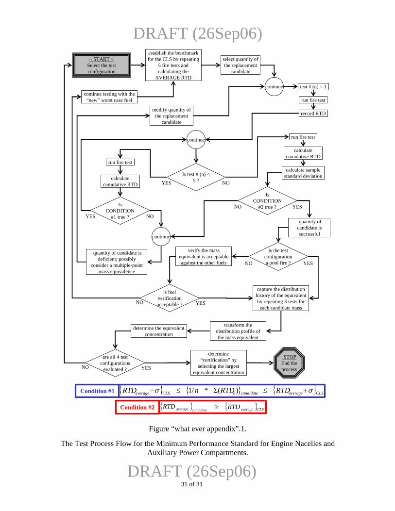
DRAFT (26Sep06)
determine “certification” by
selecting the largest equivalent concentration
capture the distribution history of the equivalent by repeating 3 tests for each candidate mass
transform the distribution profile of the mass equivalent
~ START ~Select the test configuration
establish the benchmark for the CLS by repeating
5 fire tests and calculating the
AVERAGE RTD
is the test configurationa pool fire ?NO YES
verify the mass equivalent is acceptable against the other fuels
is fuel verification acceptable ?NO YES
continue testing with the “new” worst case fuel
determine the equivalent concentration
STOP End the process
{ } { } { }CLSaveragecandidatenCLSaverage RTDRTDnRTD σσ +≤Σ≤− )(*/1Condition #1
{ } { }CLSaverageaverage candidate RTDRTD ≥
select quantity ofthe replacement
candidate
DRAFT (26Sep06)
Condition #2
are all 4 testconfigurations
evaluated ?NO YES
run fire test
run fire test
continue
quantity of candidate is deficient; possibly
consider a multiple-point mass equivalence
calculatecumulative RTD
record RTD
run fire test
calculatecumulative RTD
calculate samplestandard deviation
quantity of candidate is successfulcontinue
modify quantity ofthe replacement
candidate
test # (n) = 1continue
Is test # (n) < 5 ?YES NO
Is CONDITION
#2 true ?NO YESIs CONDITION
#1 true ?YES NO
Figure “what ever appendix”.1.
The Test Process Flow for the Minimum Performance Standard for Engine Nacelles and Auxiliary Power Compartments.
31 of 31
Recommended