Multibeam Technical HandbookPurlin & Cladding Rail Systems
Structural Products & Systems UK & Republic of Ireland
2 MultibeamKingspan Multibeam
3 Multibeam Kingspan Multibeam
Introduction 4
Multibeam 6Product Overview 6
Roof PurlinsProduct Overview 10Spanning Systems 11Anti-Sag Requirements 12Purlin Restraints 14Dimensions and References 1895mm Flange Multibeam 2695mm Flange Multibeam Restraints 27Section Properties 29Load / Span Tables 30Construction Details 44
Eaves Beam 52Product Overview 54Restraint Systems 55Dimensions and References 56Section Properties & Capacities 59Load Charts 60Loadings 61Construction Details 62
Cladding Rails 66Product Overview 68Spanning Systems 69Cladding Types 70Cladding Rail Restraints 71Cladding Rail Systems 72Firewall 74Dimensions and References 77Section Properties 85Load / Span Tables 86Construction Details 94
Multichannel 100Product Overview 102Multichannel Restraints 104New Pre-Assembled Cladding Support System 105Cladding Rail Systems 106Applications 108Dimensions and References 110Section Properties 118Load / Span Tables 119Construction Details 128
Ordering Methods 136
Case Studies 140
Design Software 144
Index 146
Eave
s Be
ams
Cla
ddin
g Ra
ilsM
ulti
chan
nel
Inde
xRo
of P
urlin
s
Contents

4 MultibeamKingspan Multibeam
Introduction
Structural Products & Systems, a sub-division of Kingspan Insulated Panels, is one of Britain’sleading designers and manufacturers of structural steel components for the construction industry. Based in Sherburn, North Yorkshire, we operate one of the largest and most advanced production complexes in Europe, manufacturing over 50,000 tonnes of steel products each year. In over five decades of trading, we have become an established market leader, renowned for our quality products and innovative designs.
Our comprehensive range of cold-rolled structural products includes composite steel floordecks, purlin and rail systems and a range of ancillary products:
Multibeam is a range of purlin and cladding rail systems that are suitable for all types of modern roof construction with bay sizes up to 15m. Multibeam cladding rail systems are designed specifically to support metal-clad walls in horizontal or vertical orientation;
Multichannel is a range of pre-engineered, structural channel sections designed to complement the Multibeam purlin and rail systems. Multichannel is an ideal solution for vertically or horizontally-laid cladding and can be an effective substitute for conventional hot-rolled sections and timber;
Multideck is a high-performance, profiled, galvanised steel floor decking for use in the construction of composite floor slabs.
5 Multibeam Kingspan Multibeam
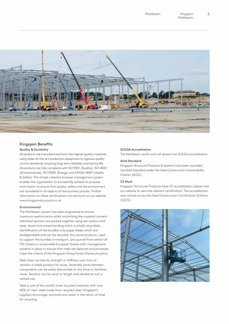
Kingspan BenefitsQuality & Durability All products are manufactured from the highest quality materials using state-of-the-art production equipment to rigorous quality control standards; ensuring long-term reliability and service life. All products are fully compliant with ISO 9001 (Quality), ISO 14001 (Environmental), ISO 50001 (Energy) and OHSAS 18001 (Health & Safety). This simple coherent business management system enables the organisation to successfully achieve its purpose and mission to ensure that quality; safety and the environment are considered in all aspects of the business process. Further information on these certifications can be found on our website www.kingspanstructural.co.uk
Environmental The Multibeam system has been engineered to ensure maximum performance whilst minimising the material content. Individual sections are packed together using low carbon mild steel, blued and waxed banding which is wholly recyclable. Identification of the bundles is by paper labels which are biodegradable and can be recycled. Any wood products, used to support the bundles in transport, are sourced from either UK FSC forests or sustainable European forests with management systems in place to ensure that trees are replaced and processes meet the criteria of the Kingspan Group Forest Disclosure policy.
Steel does not lose its strength or stiffness over time so remains a viable product for reuse. Assembly joints between components can be easily dismantled at any time to facilitate reuse. Sections can be recut to length and reholed to suit a revised use.
Steel is one of the world’s most recycled materials with over 40% of ‘new’ steel made from recycled steel. Kingspan’s suppliers encourage, promote and assist in the return of steel for recycling.
SCILGA Accreditation The Multibeam purlin and rail system has SCILGA accreditation.
Gold Standard Kingspan Structural Products & Systems have been awarded the Gold Standard under the Steel Construction Sustainability Charter (SCSC).
CE Mark Kingspan Structural Products have CE accreditation; please visit our website to view the relevant certification. The accreditation was carried out by the Steel Construction Certification Scheme (SCCS).
6 MultibeamKingspan Multibeam
Product Overview
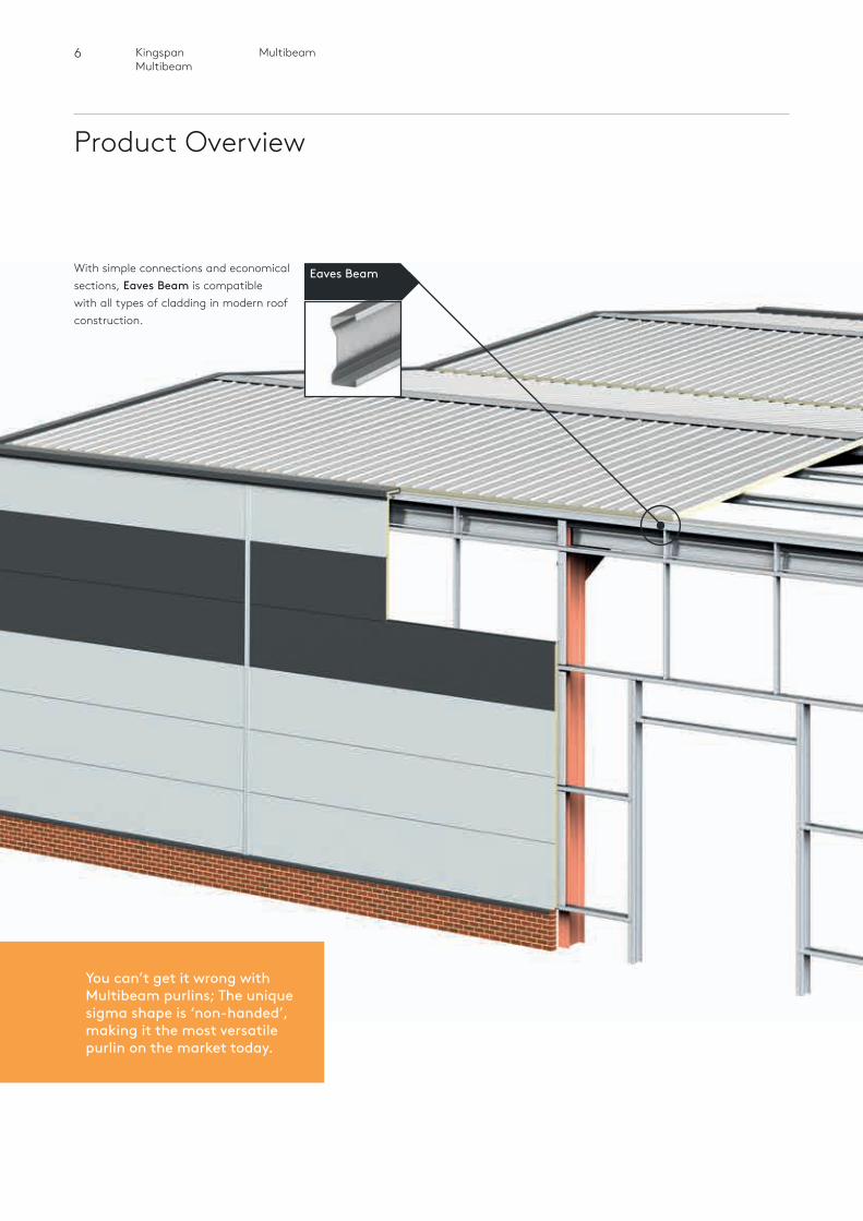
With simple connections and economical sections, Eaves Beam is compatible with all types of cladding in modern roof construction.
You can’t get it wrong with Multibeam purlins; The unique sigma shape is ‘non-handed’, making it the most versatile purlin on the market today.
Eaves Beam
7 Multibeam Kingspan Multibeam
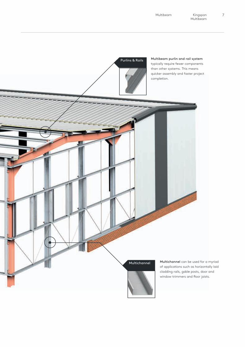
Multibeam purlin and rail systemtypically require fewer components than other systems. This means quicker assembly and faster project completion.
Multichannel can be used for a myriad of applications such as horizontally laid cladding rails, gable posts, door and window trimmers and floor joists.
Purlins & Rails
Multichannel

Heading
8 Roof Purlins
Kingspan Multibeam
Roof Purlins
Heading
9
Roof
Pur
lins
10 Roof PurlinsKingspan Multibeam
Product Overview
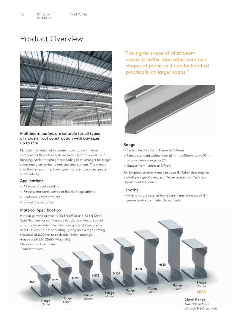
Multibeam purlins are suitable for all types of modern roof construction with bay sizes up to 15m.
Multibeam is designed to create a structure with fewer components than other systems and is lighter for easier site handling, stiffer for straighter cladding lines, stronger for longer spans and greener due to reduced steel content. This means that it saves you time, lowers your costs and provides greater sustainability.
ApplicationsAll types of roof claddingPitched, mansard, curved or flat roof applicationsRoof slopes from 0°to 60°Bay widths up to 15m
Material SpecificationHot dip galvanised steel to BS EN 10346 and BS EN 10143 ‘specifications for continuously hot dip zinc /metal coated structural steel strip’. The minimum grade of steel used is S450GD, with Z275 zinc coating, giving an average coating thickness of 0.02mm to each side. Other coatings maybe available (G600 / Magnelis). Please contact our Sales Team for advice.
RangeSection heights from 145mm to 350mmFlange standard widths from 65mm to 90mm, up to 95mm
also available (see page 26)Gauges from 1.2mm to 2.7mm
For full product dimensions see page 18. Other sizes may be available on specific request. Please contact our Technical Department for advice.
LengthsAll lengths are catered for; requirements in excess of 18m,
please contact our Sales Department.
M145 M175 M205M235
M265M300
M350
Flange 65mm
Flange 65mm
Flange 65mm
Flange 65mm
Flange 65mm
Flange 90mm
Flange 90mm
Flange 95mm
“ The sigma shape of Multibeam makes it stiffer than other common shapes of purlin so it can be handled practically on larger spans ”
NEW95mm Flange Available in M175 through M265 sections
11 Roof Purlins Kingspan Multibeam
Roof
Pur
lins
Spanning Systems
System Types
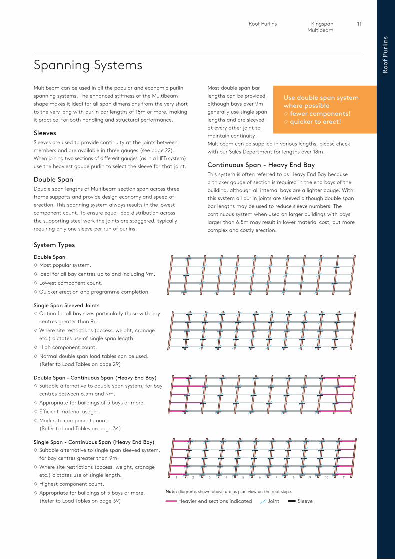
Double SpanMost popular system. Ideal for all bay centres up to and including 9m. Lowest component count.Quicker erection and programme completion.
Single Span Sleeved JointsOption for all bay sizes particularly those with bay
centres greater than 9m. Where site restrictions (access, weight, cranage
etc.) dictates use of single span length.High component count.Normal double span load tables can be used. (Refer to Load Tables on page 29)
Double Span – Continuous Span (Heavy End Bay) Suitable alternative to double span system, for bay
centres between 6.5m and 9m.Appropriate for buildings of 5 bays or more.Efficient material usage.Moderate component count. (Refer to Load Tables on page 34)
Single Span - Continuous Span (Heavy End Bay)Suitable alternative to single span sleeved system,
for bay centres greater than 9m. Where site restrictions (access, weight, cranage
etc.) dictates use of single length.Highest component count.Appropriate for buildings of 5 bays or more. (Refer to Load Tables on page 39)
Multibeam can be used in all the popular and economic purlin spanning systems. The enhanced stiffness of the Multibeam shape makes it ideal for all span dimensions from the very short to the very long with purlin bar lengths of 18m or more, making it practical for both handling and structural performance.
SleevesSleeves are used to provide continuity at the joints between members and are available in three gauges (see page 22). When joining two sections of different gauges (as in a HEB system) use the heaviest gauge purlin to select the sleeve for that joint.
Double SpanDouble span lengths of Multibeam section span across three frame supports and provide design economy and speed of erection. This spanning system always results in the lowest component count. To ensure equal load distribution across the supporting steel work the joints are staggered, typically requiring only one sleeve per run of purlins.
Most double span bar lengths can be provided, although bays over 9m generally use single span lengths and are sleeved at every other joint to maintain continuity. Multibeam can be supplied in various lengths, please check with our Sales Department for lengths over 18m.
Continuous Span - Heavy End BayThis system is often referred to as Heavy End Bay because a thicker gauge of section is required in the end bays of the building, although all internal bays are a lighter gauge. With this system all purlin joints are sleeved although double span bar lengths may be used to reduce sleeve numbers. The continuous system when used on larger buildings with bays larger than 6.5m may result in lower material cost, but more complex and costly erection.
1 2 3 4 5 6 7 8 9 10 11
Note: diagrams shown above are as plan view on the roof slope.
Heavier end sections indicated Joint Sleeve
Use double span system where possible fewer components! quicker to erect!
12 Roof PurlinsKingspan Multibeam
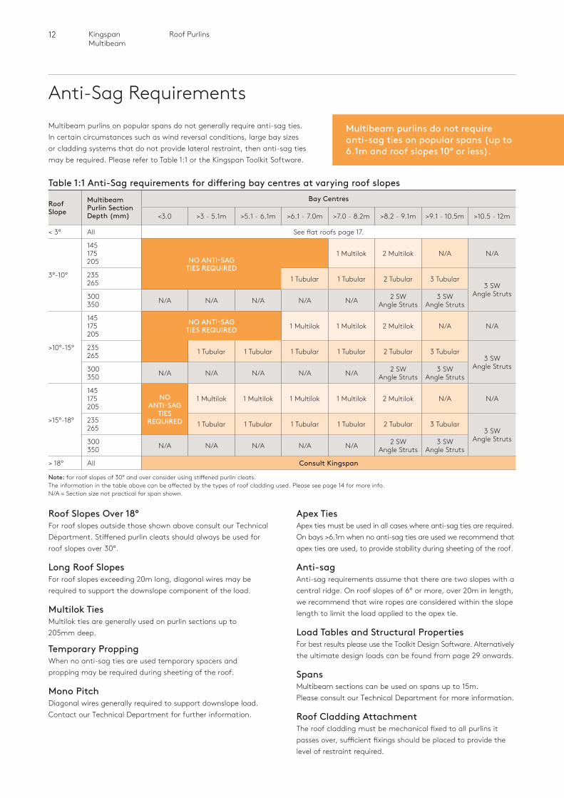
Anti-Sag RequirementsMultibeam purlins on popular spans do not generally require anti-sag ties. In certain circumstances such as wind reversal conditions, large bay sizes or cladding systems that do not provide lateral restraint, then anti-sag ties may be required. Please refer to Table 1:1 or the Kingspan Toolkit Software.
Table 1:1 Anti-Sag requirements for differing bay centres at varying roof slopes
Roof Slope
Multibeam Purlin Section Depth (mm)
Bay Centres
<3.0 >3 - 5.1m >5.1 - 6.1m >6.1 - 7.0m >7.0 - 8.2m >8.2 - 9.1m >9.1 - 10.5m >10.5 - 12m
< 3° All See flat roofs page 17.
3°-10°
145175205 NO ANTI-SAG
TIES REQUIRED
1 Multilok 2 Multilok N/A N/A
235265 1 Tubular 1 Tubular 2 Tubular 3 Tubular
3 SWAngle Struts300
350 N/A N/A N/A N/A N/A 2 SWAngle Struts
3 SWAngle Struts
>10°-15°
145175205
NO ANTI-SAG TIES REQUIRED 1 Multilok 1 Multilok 2 Multilok N/A N/A
235265 1 Tubular 1 Tubular 1 Tubular 1 Tubular 2 Tubular 3 Tubular
3 SWAngle Struts300
350 N/A N/A N/A N/A N/A 2 SWAngle Struts
3 SWAngle Struts
>15°-18°
145175205
NO ANTI-SAG
TIES REQUIRED
1 Multilok 1 Multilok 1 Multilok 1 Multilok 2 Multilok N/A N/A
235265 1 Tubular 1 Tubular 1 Tubular 1 Tubular 2 Tubular 3 Tubular
3 SWAngle Struts300
350 N/A N/A N/A N/A N/A 2 SWAngle Struts
3 SWAngle Struts
> 18° All Consult Kingspan
Note: for roof slopes of 30° and over consider using stiffened purlin cleats. The information in the table above can be affected by the types of roof cladding used. Please see page 14 for more info. N/A = Section size not practical for span shown.
Multibeam purlins do not require anti-sag ties on popular spans (up to 6.1m and roof slopes 10° or less).
Roof Slopes Over 18°For roof slopes outside those shown above consult our Technical Department. Stiffened purlin cleats should always be used for roof slopes over 30°.
Long Roof SlopesFor roof slopes exceeding 20m long, diagonal wires may be required to support the downslope component of the load.
Multilok TiesMultilok ties are generally used on purlin sections up to 205mm deep.
Temporary ProppingWhen no anti-sag ties are used temporary spacers and propping may be required during sheeting of the roof.
Mono PitchDiagonal wires generally required to support downslope load. Contact our Technical Department for further information.
Apex TiesApex ties must be used in all cases where anti-sag ties are required. On bays >6.1m when no anti-sag ties are used we recommend that apex ties are used, to provide stability during sheeting of the roof.
Anti-sagAnti-sag requirements assume that there are two slopes with a central ridge. On roof slopes of 6º or more, over 20m in length, we recommend that wire ropes are considered within the slope length to limit the load applied to the apex tie.
Load Tables and Structural PropertiesFor best results please use the Toolkit Design Software. Alternatively the ultimate design loads can be found from page 29 onwards.
SpansMultibeam sections can be used on spans up to 15m. Please consult our Technical Department for more information.
Roof Cladding AttachmentThe roof cladding must be mechanical fixed to all purlins it passes over, sufficient fixings should be placed to provide the level of restraint required.
13 Roof Purlins Kingspan Multibeam
Roof
Pur
lins
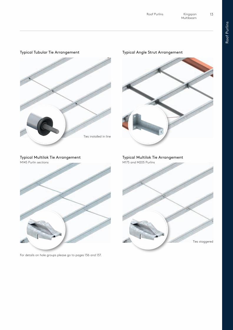
Typical Tubular Tie Arrangement
Typical Multilok Tie Arrangement M145 Purlin sections
Typical Angle Strut Arrangement
Typical Multilok Tie Arrangement M175 and M205 Purlins
Ties installed in line
Ties staggered
For details on hole groups please go to pages 136 and 137.
14 Roof PurlinsKingspan Multibeam
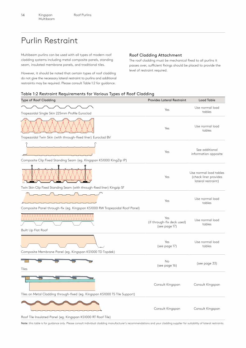
Purlin RestraintMultibeam purlins can be used with all types of modern roof cladding systems including metal composite panels, standing seam, insulated membrane panels, and traditional tiles.
However, it should be noted that certain types of roof cladding do not give the necessary lateral restraint to purlins and additional restraints may be required. Please consult Table 1:2 for guidance.
Roof Cladding AttachmentThe roof cladding must be mechanical fixed to all purlins it passes over, sufficient fixings should be placed to provide the level of restraint required.
Table 1:2 Restraint Requirements for Various Types of Roof CladdingType of Roof Cladding Provides Lateral Restraint Load Table
Trapezoidal Single Skin 225mm Profile EurocladYes Use normal load
tables
Trapezoidal Twin Skin (with through-fixed liner) Euroclad BV
Yes Use normal load tables
Composite Clip Fixed Standing Seam (eg. Kingspan KS1000 KingZip IP)
Yes See additional information opposite
Twin Skin Clip Fixed Standing Seam (with through-fixed liner) Kingzip SF
YesUse normal load tables
(check liner provides lateral restraint)
Composite Panel through-fix (eg. Kingspan KS1000 RW Trapezoidal Roof Panel)
Yes Use normal load tables
Built Up Flat Roof
Yes (if through-fix deck used)
(see page 17)
Use normal load tables
Composite Membrane Panel (eg. Kingspan KS1000 TD Topdek)
Yes (see page 17)
Use normal load tables
Tiles
No (see page 16) (see page 33)
Tiles on Metal Cladding through-fixed (eg. Kingspan KS1000 TS Tile Support)
Consult Kingspan Consult Kingspan
Roof Tile Insulated Panel (eg. Kingspan KS1000 RT Roof Tile)
Consult Kingspan Consult Kingspan
Note: this table is for guidance only. Please consult individual cladding manufacturer’s recommendations and your cladding supplier for suitability of lateral restraints.
15 Roof Purlins Kingspan Multibeam
Roof
Pur
lins
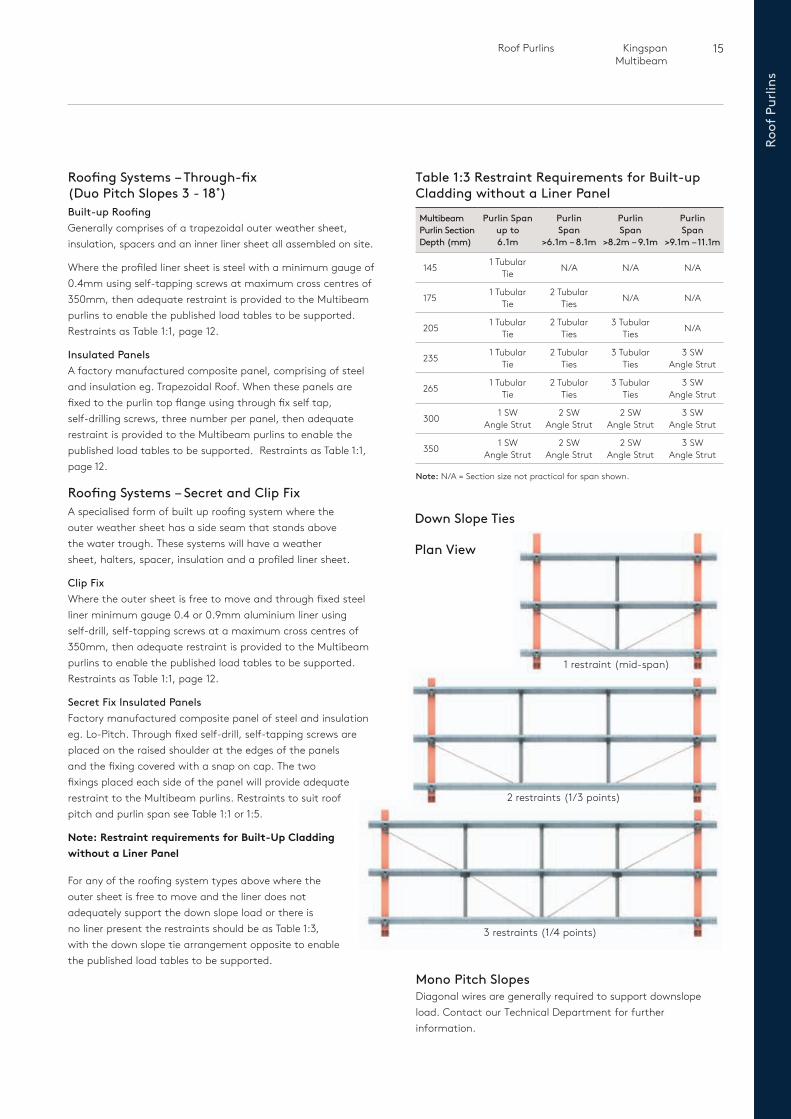
Table 1:3 Restraint Requirements for Built-up Cladding without a Liner Panel
Multibeam Purlin Section Depth (mm)
Purlin Span up to 6.1m
Purlin Span
>6.1m – 8.1m
Purlin Span
>8.2m – 9.1m
Purlin Span
>9.1m – 11.1m
145 1 Tubular Tie N/A N/A N/A
175 1 Tubular Tie
2 Tubular Ties N/A N/A
205 1 Tubular Tie
2 Tubular Ties
3 Tubular Ties N/A
235 1 Tubular Tie
2 Tubular Ties
3 Tubular Ties
3 SW Angle Strut
265 1 Tubular Tie
2 Tubular Ties
3 Tubular Ties
3 SW Angle Strut
300 1 SW Angle Strut
2 SW Angle Strut
2 SW Angle Strut
3 SW Angle Strut
350 1 SW Angle Strut
2 SW Angle Strut
2 SW Angle Strut
3 SW Angle Strut
Note: N/A = Section size not practical for span shown.
2 restraints (1/3 points)
3 restraints (1/4 points)
Plan View
1 restraint (mid-span)
Down Slope Ties
Mono Pitch SlopesDiagonal wires are generally required to support downslope load. Contact our Technical Department for further information.
Roofing Systems – Through-fix (Duo Pitch Slopes 3 - 18˚)Built-up RoofingGenerally comprises of a trapezoidal outer weather sheet, insulation, spacers and an inner liner sheet all assembled on site.
Where the profiled liner sheet is steel with a minimum gauge of 0.4mm using self-tapping screws at maximum cross centres of 350mm, then adequate restraint is provided to the Multibeam purlins to enable the published load tables to be supported. Restraints as Table 1:1, page 12.
Insulated Panels A factory manufactured composite panel, comprising of steel and insulation eg. Trapezoidal Roof. When these panels are fixed to the purlin top flange using through fix self tap, self-drilling screws, three number per panel, then adequate restraint is provided to the Multibeam purlins to enable the published load tables to be supported. Restraints as Table 1:1, page 12.
Roofing Systems – Secret and Clip FixA specialised form of built up roofing system where the outer weather sheet has a side seam that stands above the water trough. These systems will have a weather sheet, halters, spacer, insulation and a profiled liner sheet.
Clip FixWhere the outer sheet is free to move and through fixed steel liner minimum gauge 0.4 or 0.9mm aluminium liner using self-drill, self-tapping screws at a maximum cross centres of 350mm, then adequate restraint is provided to the Multibeam purlins to enable the published load tables to be supported. Restraints as Table 1:1, page 12.
Secret Fix Insulated PanelsFactory manufactured composite panel of steel and insulation eg. Lo-Pitch. Through fixed self-drill, self-tapping screws are placed on the raised shoulder at the edges of the panels and the fixing covered with a snap on cap. The two fixings placed each side of the panel will provide adequate restraint to the Multibeam purlins. Restraints to suit roof pitch and purlin span see Table 1:1 or 1:5.
Note: Restraint requirements for Built-Up Cladding without a Liner Panel
For any of the roofing system types above where the outer sheet is free to move and the liner does not adequately support the down slope load or there is no liner present the restraints should be as Table 1:3, with the down slope tie arrangement opposite to enable the published load tables to be supported.
16 Roof PurlinsKingspan Multibeam
Purlin Restraint
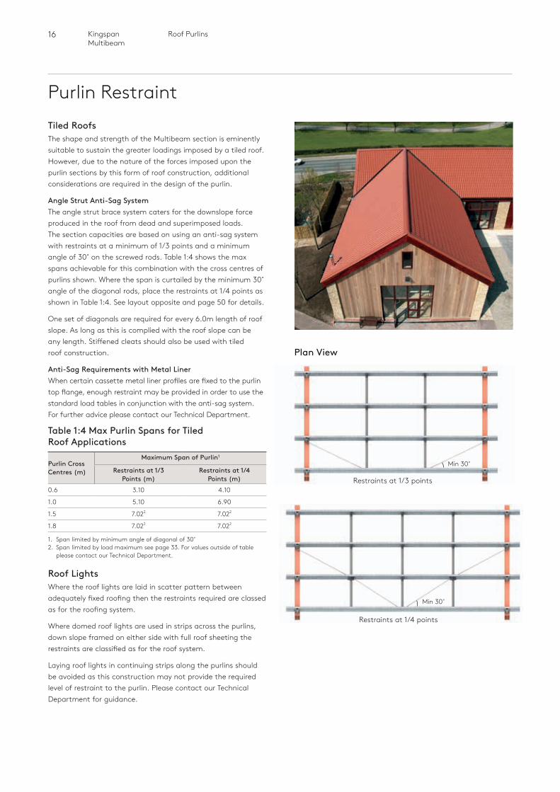
Plan View
Min 30˚
Restraints at 1/4 points
Restraints at 1/3 points
Min 30˚
Tiled RoofsThe shape and strength of the Multibeam section is eminently suitable to sustain the greater loadings imposed by a tiled roof.However, due to the nature of the forces imposed upon the purlin sections by this form of roof construction, additional considerations are required in the design of the purlin.
Angle Strut Anti-Sag SystemThe angle strut brace system caters for the downslope force produced in the roof from dead and superimposed loads. The section capacities are based on using an anti-sag system with restraints at a minimum of 1/3 points and a minimum angle of 30˚ on the screwed rods. Table 1:4 shows the max spans achievable for this combination with the cross centres of purlins shown. Where the span is curtailed by the minimum 30˚ angle of the diagonal rods, place the restraints at 1/4 points as shown in Table 1:4. See layout opposite and page 50 for details.
One set of diagonals are required for every 6.0m length of roof slope. As long as this is complied with the roof slope can be any length. Stiffened cleats should also be used with tiled roof construction.
Anti-Sag Requirements with Metal LinerWhen certain cassette metal liner profiles are fixed to the purlin top flange, enough restraint may be provided in order to use the standard load tables in conjunction with the anti-sag system. For further advice please contact our Technical Department.
Table 1:4 Max Purlin Spans for Tiled Roof Applications
Purlin Cross Centres (m)
Maximum Span of Purlin1
Restraints at 1/3 Points (m)
Restraints at 1/4 Points (m)
0.6 3.10 4.10
1.0 5.10 6.90
1.5 7.022 7.022
1.8 7.022 7.022
1. Span limited by minimum angle of diagonal of 30˚2. Span limited by load maximum see page 33. For values outside of table
please contact our Technical Department.
Roof LightsWhere the roof lights are laid in scatter pattern between adequately fixed roofing then the restraints required are classed as for the roofing system.
Where domed roof lights are used in strips across the purlins, down slope framed on either side with full roof sheeting the restraints are classified as for the roof system.
Laying roof lights in continuing strips along the purlins should be avoided as this construction may not provide the required level of restraint to the purlin. Please contact our Technical Department for guidance.
17 Roof Purlins Kingspan Multibeam
Roof
Pur
lins
Low Pitch and Flat Roofing System (Roof slopes 3˚ or less)For this application the term ‘Flat Roof’ generally means any roof with a roofslope no greater than 1:20 or 3°.
Built up Standing Seam Roofing Systems A specialised form of built up roofing system where the outer weather sheet has a side seam that stands above the water trough. These systems will have a weather sheet, halters, spacers, insulation and a liner sheet. Typically this system can be classed as clip fixed where the outer sheet is free to move or is fixed.
Where the outer sheet is free to move and has a through fixed profiled steel liner minimum gauge 0.4mm fixed using self-drill, self-tapping screws at a maximum cross centres of 350mm, then adequate restraint is provided to the Multibeam purlins to enable the published load tables to be supported. Restraints as Table 1:5.
Clip fixed, where the outer sheet is free to move and no steel liner then restraints must be provided as shown in Table 1:3 on page 15 to enable the published load tables to be supported.
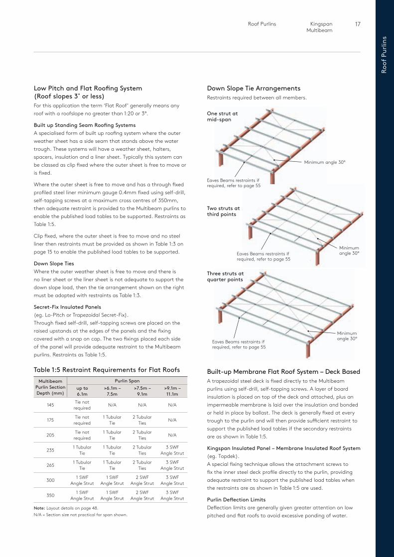
Down Slope Ties Where the outer weather sheet is free to move and there is no liner sheet or the liner sheet is not adequate to support the down slope load, then the tie arrangement shown on the right must be adopted with restraints as Table 1:3.
Secret-Fix Insulated Panels (eg. Lo-Pitch or Trapezoidal Secret-Fix).Through fixed self-drill, self-tapping screws are placed on the raised upstands at the edges of the panels and the fixing covered with a snap on cap. The two fixings placed each side of the panel will provide adequate restraint to the Multibeam purlins. Restraints as Table 1:5.
Down Slope Tie Arrangements Restraints required between all members.
Built-up Membrane Flat Roof System – Deck Based A trapezoidal steel deck is fixed directly to the Multibeam purlins using self-drill, self-tapping screws. A layer of board insulation is placed on top of the deck and attached, plus an impermeable membrane is laid over the insulation and bonded or held in place by ballast. The deck is generally fixed at every trough to the purlin and will then provide sufficient restraint to support the published load tables if the secondary restraints are as shown in Table 1:5.
Kingspan Insulated Panel – Membrane Insulated Roof System (eg. Topdek).A special fixing technique allows the attachment screws to fix the inner steel deck profile directly to the purlin, providing adequate restraint to support the published load tables when the restraints are as shown in Table 1:5 are used.
Purlin Deflection Limits Deflection limits are generally given greater attention on low pitched and flat roofs to avoid excessive ponding of water.
Table 1:5 Restraint Requirements for Flat RoofsMultibeam
Purlin Section Depth (mm)
Purlin Spanup to 6.1m
>6.1m – 7.5m
>7.5m – 9.1m
>9.1m – 11.1m
145 Tie not required N/A N/A N/A
175 Tie not required
1 Tubular Tie
2 Tubular Ties N/A
205 Tie not required
1 Tubular Tie
2 Tubular Ties N/A
235 1 Tubular Tie
1 Tubular Tie
2 Tubular Ties
3 SWF Angle Strut
265 1 Tubular Tie
1 Tubular Tie
2 Tubular Ties
3 SWF Angle Strut
300 1 SWF Angle Strut
1 SWF Angle Strut
2 SWF Angle Strut
3 SWF Angle Strut
350 1 SWF Angle Strut
1 SWF Angle Strut
2 SWF Angle Strut
3 SWF Angle Strut
Note: Layout details on page 48.N/A = Section size not practical for span shown.
Minimum angle 30°
Eaves Beams restraints if required, refer to page 55
One strut at mid-span
Three struts at quarter points
Two struts at third points
Minimum angle 30°
Minimum angle 30°
Eaves Beams restraints if required, refer to page 55
Eaves Beams restraints if required, refer to page 55
18 Roof PurlinsKingspan Multibeam
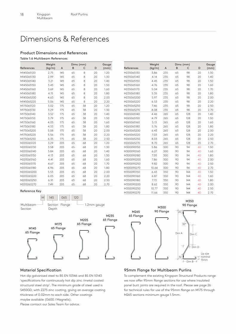
Dimensions & References
Weight Dims (mm) GaugeReferences (kg/m) A B C D (mm)M235065130 3.86 235 65 98 20 1.30M235065140 4.14 235 65 98 20 1.40M235065150 4.45 235 65 98 20 1.50M235065160 4.76 235 65 98 20 1.60M235065170 5.04 235 65 98 20 1.70M235065180 5.35 235 65 98 20 1.80M235065200 5.97 235 65 98 20 2.00M235065220 6.53 235 65 98 20 2.20M235065250 7.46 235 65 98 20 2.50M235065270 8.08 235 65 98 20 2.70M265065140 4.46 265 65 128 20 1.40M265065150 4.79 265 65 128 20 1.50M265065160 5.13 265 65 128 20 1.60M265065180 5.76 265 65 128 20 1.80M265065200 6.43 265 65 128 20 2.00M265065220 7.03 265 65 128 20 2.20M265065250 8.03 265 65 128 20 2.50M265065270 8.70 265 65 128 20 2.70M300090150 5.86 300 90 94 40 1.50M300090160 6.27 300 90 94 40 1.60M300090180 7.05 300 90 94 40 1.80M300090200 7.86 300 90 94 40 2.00M300090250 9.82 300 90 94 40 2.50M300090270 10.64 300 90 94 40 2.70M350090150 6.43 350 90 144 40 1.50M350090160 6.87 350 90 144 40 1.60M350090180 7.72 350 90 144 40 1.80M350090200 8.62 350 90 144 40 2.00M350090250 10.77 350 90 144 40 2.50M350090270 11.66 350 90 144 40 2.70
Section Depth
FlangeMultibeam Section
1.2mm gauge
M 145 065 120
Reference Key
M30090 FlangeM265
65 FlangeM23565 FlangeM205
65 FlangeM17565 FlangeM145
65 Flange
M35090 Flange
Lip size nominal 15mmDim B
30º
Dim A
20
Dim C
32
Dim D
Product Dimensions and ReferencesTable 1:6 Multibeam References
Weight Dims (mm) GaugeReferences (kg/m) A B C D (mm)M145065120 2.75 145 65 8 20 1.20M145065130 2.99 145 65 8 20 1.30M145065140 3.21 145 65 8 20 1.40M145065150 3.45 145 65 8 20 1.50M145065160 3.69 145 65 8 20 1.60M145065180 4.15 145 65 8 20 1.80M145065200 4.63 145 65 8 20 2.00M145065220 5.06 145 65 8 20 2.20M175065120 3.02 175 65 38 20 1.20M175065130 3.29 175 65 38 20 1.30M175065140 3.52 175 65 38 20 1.40M175065150 3.79 175 65 38 20 1.50M175065160 4.05 175 65 38 20 1.60M175065180 4.55 175 65 38 20 1.80M175065200 5.08 175 65 38 20 2.00M175065220 5.56 175 65 38 20 2.20M175065250 6.35 175 65 38 20 2.50M205065120 3.29 205 65 68 20 1.20M205065130 3.58 205 65 68 20 1.30M205065140 3.84 205 65 68 20 1.40M205065150 4.13 205 65 68 20 1.50M205065160 4.41 205 65 68 20 1.60M205065170 4.67 205 65 68 20 1.70M205065180 4.96 205 65 68 20 1.80M205065200 5.53 205 65 68 20 2.00M205065220 6.05 205 65 68 20 2.20M205065250 6.91 205 65 68 20 2.50M205065270 7.49 205 65 68 20 2.70
Material SpecificationHot dip galvanised steel to BS EN 10346 and BS EN 10143 ‘specifications for continuously hot dip zinc /metal coated structural steel strip’. The minimum grade of steel used is S450GD, with Z275 zinc coating, giving an average coating thickness of 0.02mm to each side. Other coatings maybe available (G600 / Magnelis). Please contact our Sales Team for advice.
95mm Flange for Multibeam PurlinsTo complement the existing Kingspan Structural Products range we now offer 95mm flange sections for use where insulated panel butt joints are required in the roof. Please see page 26 for technical rules for use of the 95mm flange on M175 through M265 sections minimum gauge 1.5mm.
19 Roof Purlins Kingspan Multibeam
Roof
Pur
lins
MD350MD300MD265
17
105
30
MD235MD205MD175MD145
MS265MS235MS205MS175MS145
30303026
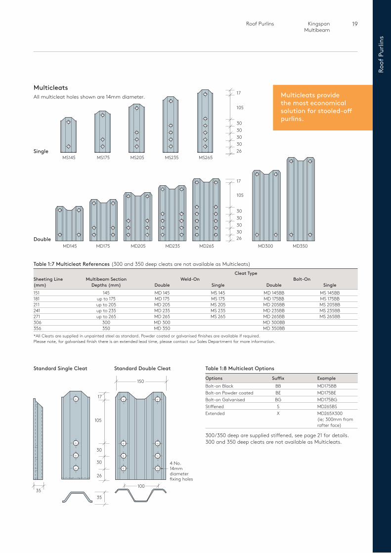
Table 1:7 Multicleat References (300 and 350 deep cleats are not available as Multicleats)
Cleat TypeSheeting Line Multibeam Section Weld-On Bolt-On(mm) Depths (mm) Double Single Double Single151 145 MD 145 MS 145 MD 145BB MS 145BB 181 up to 175 MD 175 MS 175 MD 175BB MS 175BB 211 up to 205 MD 205 MS 205 MD 205BB MS 205BB 241 up to 235 MD 235 MS 235 MD 235BB MS 235BB 271 up to 265 MD 265 MS 265 MD 265BB MS 265BB306 300 MD 300 MD 300BB 356 350 MD 350 MD 350BB * All Cleats are supplied in unpainted steel as standard. Powder coated or galvanised finishes are available if required.Please note, for galvanised finish there is an extended lead time, please contact our Sales Department for more information.
30303030
17
105
26
MulticleatsAll multicleat holes shown are 14mm diameter.
Single
Double
4 No. 14mm diameter fixing holes
Standard Double CleatStandard Single Cleat
26
35
30
30
17
105
100
150
35
Table 1:8 Multicleat Options
Options Suffix ExampleBolt-on Black BB MD175BBBolt-on Powder coated BE MD175BEBolt-on Galvanised BG MD175BGStiffened S MD265BSExtended X MD265X300 (ie; 300mm from
rafter face)
300/350 deep are supplied stiffened, see page 21 for details.300 and 350 deep cleats are not available as Multicleats.
Multicleats provide the most economical solution for stooled-off purlins.
20 Roof PurlinsKingspan Multibeam
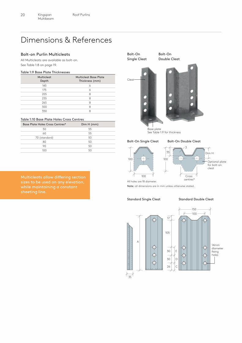
Dimensions & ReferencesBolt-on Purlin MulticleatsAll Multicleats are available as bolt-on. See Table 1:8 on page 19.
Table 1:9 Base Plate Thicknesses Multicleat Multicleat Base Plate Depth Thickness (mm) 145 6 175 6 205 8 235 8 265 8 300 8 350 8
Table 1:10 Base Plate Holes Cross Centres Base Plate Holes Cross Centres* Dim H (mm) 50 55 60 55 70 (standard) 50 80 50 90 50 100 50
Base plateSee Table 1:9 for thickness
Bolt-On Single Cleat
Bolt-On Double Cleat
Bolt-On Single Cleat
3
Optional plate for bolt-on cleat
Dim H
100
35
Cross centres*
100
100
Bolt-On Double Cleat
All holes are 18 diameter.
Note: all dimensions are in mm unless otherwise stated.
26
30
30
C
D
E
14mm diameter fixing holes
Standard Double CleatStandard Single Cleat
17
105
100150
35
A
Cleat
Multicleats allow differing section sizes to be used on any elevation, while maintaining a constant sheeting line.
21 Roof Purlins Kingspan Multibeam
Roof
Pur
lins
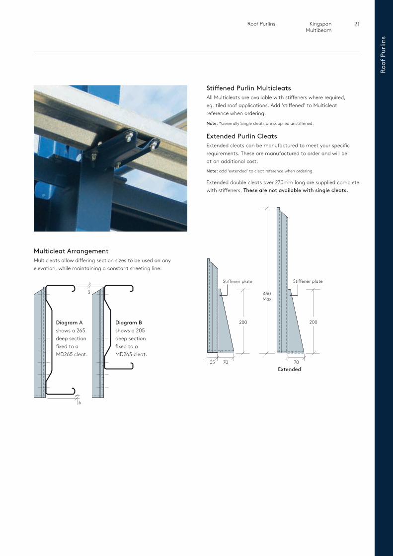
Stiffened Purlin MulticleatsAll Multicleats are available with stiffeners where required, eg. tiled roof applications. Add ‘stiffened’ to Multicleat reference when ordering.
Note: *Generally Single cleats are supplied unstiffened.
Extended Purlin CleatsExtended cleats can be manufactured to meet your specific requirements. These are manufactured to order and will be at an additional cost.
Note: add ‘extended’ to cleat reference when ordering.
Extended double cleats over 270mm long are supplied complete with stiffeners. These are not available with single cleats.
Multicleat ArrangementMulticleats allow differing section sizes to be used on any elevation, while maintaining a constant sheeting line.
3
6
Diagram Ashows a 265 deep section fixed to a MD265 cleat.
Diagram Bshows a 205 deep section fixed to a MD265 cleat.
Stiffener plate
450 Max
200
707035
Stiffener plate
200
Extended
22 Roof PurlinsKingspan Multibeam
Dimensions & References
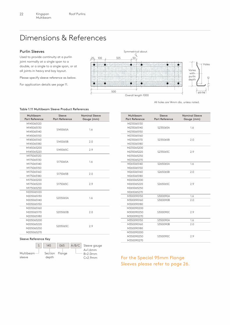
Table 1:11 Multibeam Sleeve Product References
Purlin SleevesUsed to provide continuity at a purlin joint normally at a single span to a double, or a single to a single span, or at all joints in heavy end bay layout.
Please specify sleeve reference as below.
For application details see page 11.
All holes are 14mm dia. unless noted.
Multibeam Sleeve Nominal Sleeve Part Reference Part Reference Gauge (mm) M145065120 M145065130
S145065A 1.6 M145065140 M145065150 M145065160
S145065B 2.0 M145065180 M145065200
S145065C 2.9 M145065220 M175065120 M175065130
S175065A 1.6 M175065140 M175065150 M175065160
S175065B 2.0 M175065180 M175065200 M175065220 S175065C 2.9 M175065250 M205065120 M205065130
S205065A 1.6 M205065140 M205065150 M205065160 M205065170 S205065B 2.0 M205065180 M205065200 M205065220
S205065C 2.9 M205065250 M205065270
Multibeam Sleeve Nominal Sleeve Part Reference Part Reference Gauge (mm) M235065130 M235065140 S235065A 1.6 M235065150 M235065160 M235065170 S235065B 2.0 M235065180 M235065200 M235065220 S235065C 2.9 M235065250 M235065270 M265065140 S265065A 1.6 M265065150 M265065160 S265065B 2.0 M265065180 M265065200 M265065220 S265065C 2.9 M265065250 M265065270 M300090150 S300090A 1.6 M300090160 S300090B 2.0 M300090180 M300090200 M300090250 S300090C 2.9 M300090270 M350090150 S350090A 1.6 M350090160 S350090B 2.0 M350090180 M350090200 M350090250 S350090C 2.9 M350090270
32510025 50
500Overall length 1000
Symmetrical about C
L
69/94
12
Holes
Varies with
purlin depth
For the Special 95mm Flange Sleeves please refer to page 26.
A=1.6mm B=2.0mm C=2.9mm
S 145 065 A/B/C Sleeve gauge
Sleeve Reference Key
Multibeam sleeve
Section depth
Flange
23 Roof Purlins Kingspan Multibeam
Roof
Pur
lins
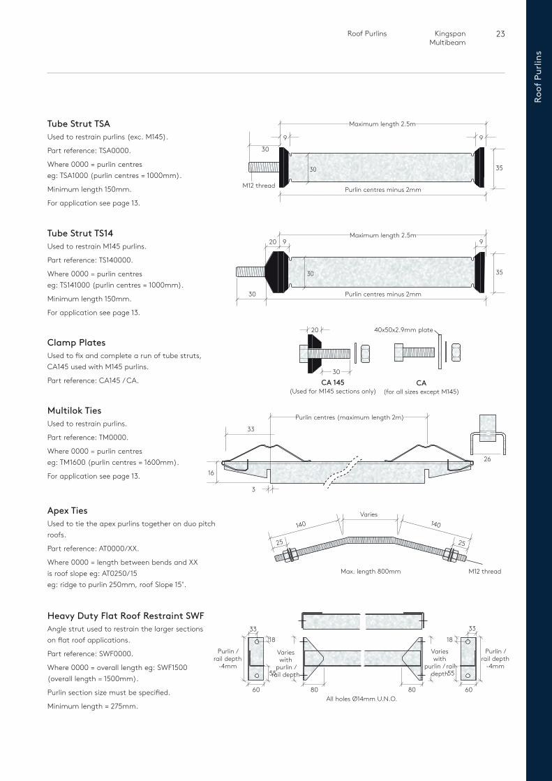
Tube Strut TSAUsed to restrain purlins (exc. M145).
Part reference: TSA0000.
Where 0000 = purlin centres eg: TSA1000 (purlin centres = 1000mm).
Minimum length 150mm.
For application see page 13.
Tube Strut TS14Used to restrain M145 purlins.
Part reference: TS140000.
Where 0000 = purlin centres eg: TS141000 (purlin centres = 1000mm).
Minimum length 150mm.
For application see page 13.
Maximum length 2.5m
Purlin centres minus 2mm
35
920 9
30
30
Purlin centres minus 2mm
3530
9
M12 thread
30
Maximum length 2.5m
9
Multilok TiesUsed to restrain purlins.
Part reference: TM0000.
Where 0000 = purlin centres eg: TM1600 (purlin centres = 1600mm).
For application see page 13. 16
33
3
26
Purlin centres (maximum length 2m)
Clamp PlatesUsed to fix and complete a run of tube struts, CA145 used with M145 purlins.
Part reference: CA145 / CA. CA 145(Used for M145 sections only)
30
20
CA(for all sizes except M145)
40x50x2.9mm plate
Apex TiesUsed to tie the apex purlins together on duo pitch roofs.
Part reference: AT0000/XX.
Where 0000 = length between bends and XX is roof slope eg: AT0250/15 eg: ridge to purlin 250mm, roof Slope 15˚.
M12 thread
140
25
140
25
Varies
Max. length 800mm
Heavy Duty Flat Roof Restraint SWFAngle strut used to restrain the larger sections on flat roof applications.
Part reference: SWF0000.
Where 0000 = overall length eg: SWF1500 (overall length = 1500mm).
Purlin section size must be specified.
Minimum length = 275mm.
80 8060
Purlin / rail depth
-4mm
Purlin / rail depth
-4mm
Varies with
purlin / rail depth55
1833
60
55
18
33
Varies with
purlin / rail depth
All holes Ø14mm U.N.O.
24 Roof PurlinsKingspan Multibeam
Dimensions & References
Maximum length 2m2525
Purlin hole 14 dia.
Mainframe hole 18 dia.
45
2.0
45
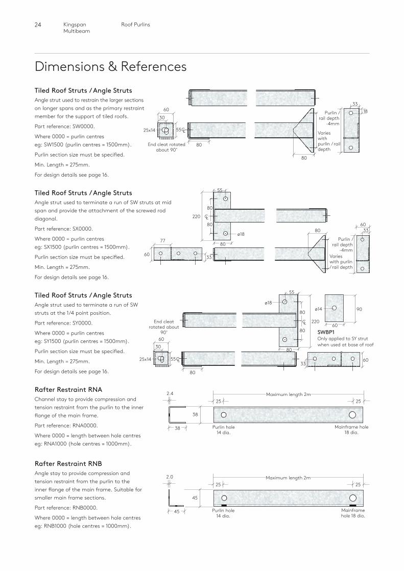
Rafter Restraint RNBAngle stay to provide compression and tension restraint from the purlin to the inner flange of the main frame. Suitable for smaller main frame sections.
Part reference: RNB0000.
Where 0000 = length between hole centreseg: RNB1000 (hole centres = 1000mm).
Tiled Roof Struts / Angle StrutsAngle strut used to restrain the larger sections on longer spans and as the primary restraint member for the support of tiled roofs.
Part reference: SW0000.
Where 0000 = purlin centres eg: SW1500 (purlin centres = 1500mm).
Purlin section size must be specified.
Min. Length = 275mm.
For design details see page 16.
End cleat rotated about 90˚
60
30
25x14 55
Purlin / rail depth
-4mm
Varies with purlin / rail depth
3318
80
80
Tiled Roof Struts / Angle StrutsAngle strut used to terminate a run of SW struts at mid span and provide the attachment of the screwed rod diagonal.
Part reference: SX0000.
Where 0000 = purlin centres eg: SX1500 (purlin centres = 1500mm).
Purlin section size must be specified.
Min. Length = 275mm.
For design details see page 16.
77 Purlin / rail depth
-4mmVaries with purlin / rail depth
6033
60 33
80
220 CL
80
80
80
ø18
55
CL
Tiled Roof Struts / Angle StrutsAngle strut used to terminate a run of SW struts at the 1/4 point position.
Part reference: SY0000.
Where 0000 = purlin centres eg: SY1500 (purlin centres = 1500mm).
Purlin section size must be specified.
Min. Length = 275mm.
For design details see page 16.
30
End cleat rotated about
90˚60
25x14 55CL
80
3360
80
220
90
CL
80
80
ø18ø14
55
60SWBP1Only applied to SY strut when used at base of roof
Rafter Restraint RNAChannel stay to provide compression and tension restraint from the purlin to the inner flange of the main frame.
Part reference: RNA0000.
Where 0000 = length between hole centreseg: RNA1000 (hole centres = 1000mm).
Maximum length 2m2525
Purlin hole 14 dia.
Mainframe hole 18 dia.
38
2.4
38
25 Roof Purlins Kingspan Multibeam
Roof
Pur
lins
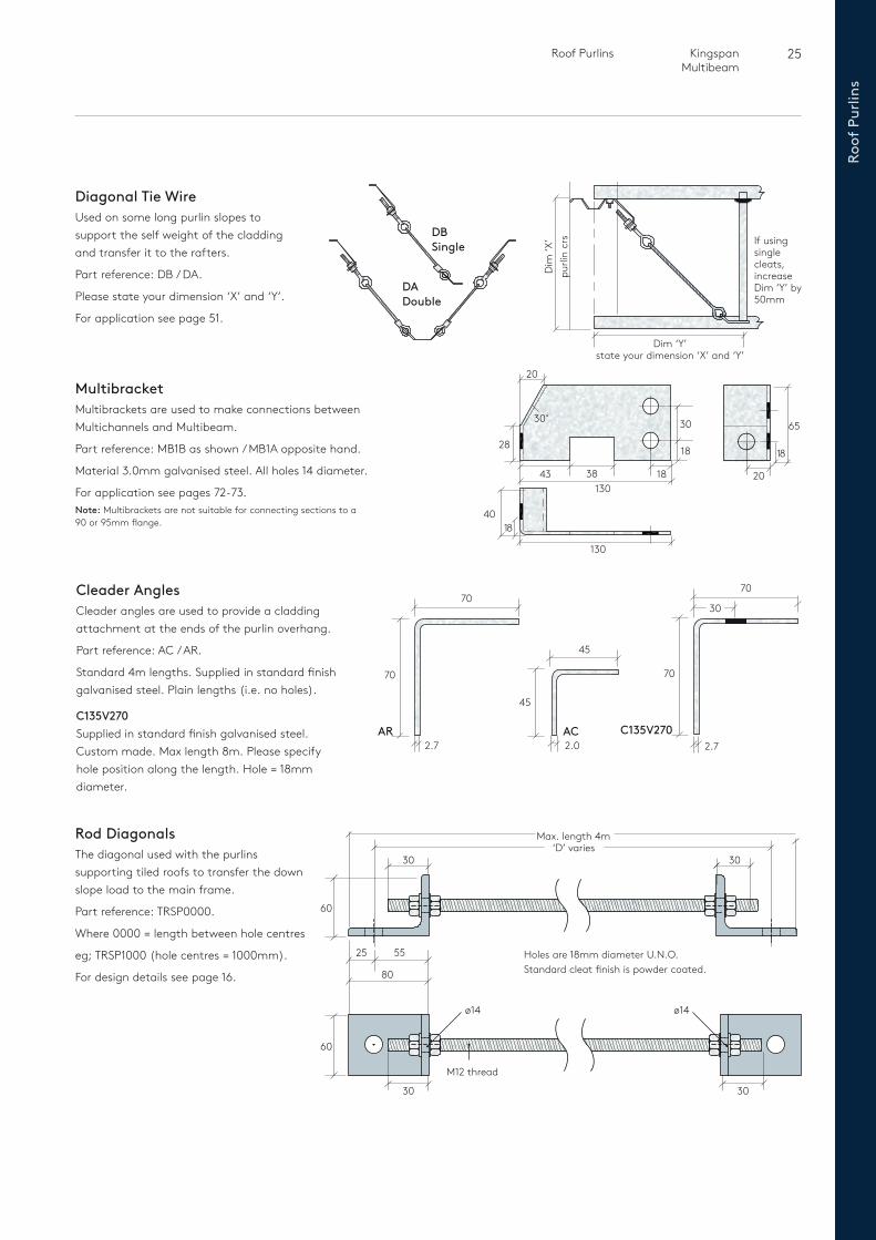
Rod DiagonalsThe diagonal used with the purlins supporting tiled roofs to transfer the down slope load to the main frame.
Part reference: TRSP0000.
Where 0000 = length between hole centres
eg; TRSP1000 (hole centres = 1000mm).
For design details see page 16.
Diagonal Tie WireUsed on some long purlin slopes to support the self weight of the cladding and transfer it to the rafters.
Part reference: DB / DA.
Please state your dimension ‘X’ and ‘Y’.
For application see page 51.
DA Double
DB Single
Dim ‘Y’ state your dimension ‘X’ and ‘Y’
purli
n cr
sD
im ‘X
’ If using single cleats, increase Dim ‘Y’ by 50mm
30
55
80
60
25
30‘D’ varies
Max. length 4m
M12 thread
ø14 ø14
Holes are 18mm diameter U.N.O.Standard cleat finish is powder coated.
60
30 30
MultibracketMultibrackets are used to make connections between Multichannels and Multibeam.
Part reference: MB1B as shown / MB1A opposite hand.
Material 3.0mm galvanised steel. All holes 14 diameter.
For application see pages 72-73.Note: Multibrackets are not suitable for connecting sections to a 90 or 95mm flange.
Cleader AnglesCleader angles are used to provide a cladding attachment at the ends of the purlin overhang.
Part reference: AC / AR.
Standard 4m lengths. Supplied in standard finish galvanised steel. Plain lengths (i.e. no holes).
C135V270Supplied in standard finish galvanised steel. Custom made. Max length 8m. Please specify hole position along the length. Hole = 18mm diameter.
45
45
AC2.72.0
70
2.7
70
AR
70
70
C135V270
30
1840
130
30
38
30˚
28
130
18
1843
20
65
18
20
26 Roof PurlinsKingspan Multibeam
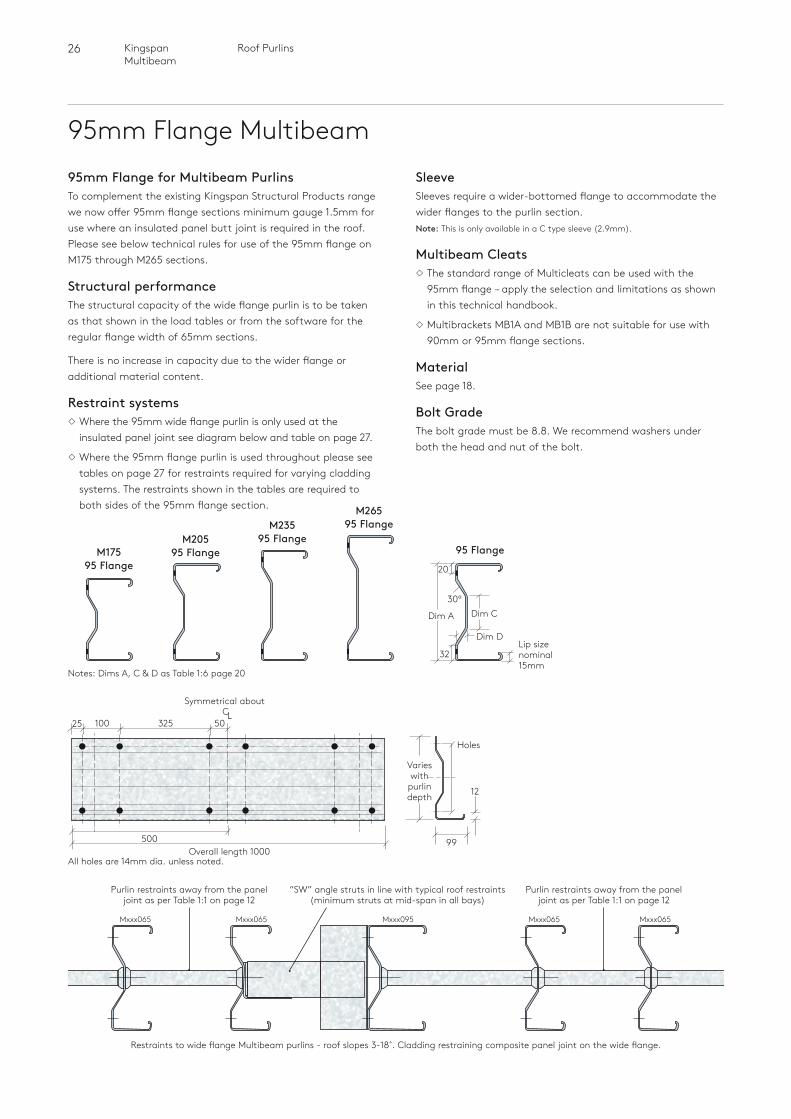
95mm Flange Multibeam95mm Flange for Multibeam PurlinsTo complement the existing Kingspan Structural Products range we now offer 95mm flange sections minimum gauge 1.5mm for use where an insulated panel butt joint is required in the roof. Please see below technical rules for use of the 95mm flange on M175 through M265 sections.
Structural performance The structural capacity of the wide flange purlin is to be taken as that shown in the load tables or from the software for the regular flange width of 65mm sections.
There is no increase in capacity due to the wider flange or additional material content.
Restraint systems Where the 95mm wide flange purlin is only used at the
insulated panel joint see diagram below and table on page 27.
Where the 95mm flange purlin is used throughout please see tables on page 27 for restraints required for varying cladding systems. The restraints shown in the tables are required to both sides of the 95mm flange section.
SleeveSleeves require a wider-bottomed flange to accommodate the wider flanges to the purlin section.Note: This is only available in a C type sleeve (2.9mm).
Multibeam Cleats The standard range of Multicleats can be used with the
95mm flange – apply the selection and limitations as shown in this technical handbook.
Multibrackets MB1A and MB1B are not suitable for use with 90mm or 95mm flange sections.
Material See page 18.
Bolt GradeThe bolt grade must be 8.8. We recommend washers under both the head and nut of the bolt.
M26595 FlangeM235
95 FlangeM20595 FlangeM175
95 Flange
All holes are 14mm dia. unless noted.
32510025 50
500Overall length 1000
Symmetrical about C
L
99
12
Holes
Varies with
purlin depth
Purlin restraints away from the panel joint as per Table 1:1 on page 12
Purlin restraints away from the panel joint as per Table 1:1 on page 12
“SW” angle struts in line with typical roof restraints (minimum struts at mid-span in all bays)
Mxxx065 Mxxx065Mxxx065 Mxxx065Mxxx095
Restraints to wide flange Multibeam purlins - roof slopes 3-18˚. Cladding restraining composite panel joint on the wide flange.
95 Flange
Lip size nominal 15mm
30º
Dim A
20
Dim C
32
Dim D
Notes: Dims A, C & D as Table 1:6 page 20
27 Roof Purlins Kingspan Multibeam
Roof
Pur
lins
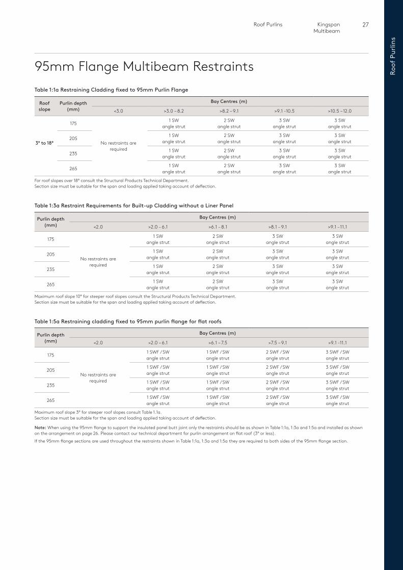
95mm Flange Multibeam RestraintsTable 1:1a Restraining Cladding fixed to 95mm Purlin Flange
Roof slope
Purlin depth(mm)
Bay Centres (m)
<3.0 >3.0 – 8.2 >8.2 – 9.1 >9.1 -10.5 >10.5 – 12.0
3° to 18°
175
No restraints are required
1 SWangle strut
2 SWangle strut
3 SWangle strut
3 SWangle strut
205 1 SWangle strut
2 SWangle strut
3 SWangle strut
3 SWangle strut
235 1 SWangle strut
2 SWangle strut
3 SWangle strut
3 SWangle strut
265 1 SWangle strut
2 SWangle strut
3 SWangle strut
3 SWangle strut
For roof slopes over 18° consult the Structural Products Technical Department.Section size must be suitable for the span and loading applied taking account of deflection.
Table 1:3a Restraint Requirements for Built-up Cladding without a Liner Panel
Purlin depth(mm)
Bay Centres (m)
<2.0 >2.0 – 6.1 >6.1 – 8.1 >8.1 – 9.1 >9.1 – 11.1
175
No restraints are required
1 SWangle strut
2 SWangle strut
3 SWangle strut
3 SWangle strut
205 1 SWangle strut
2 SWangle strut
3 SWangle strut
3 SWangle strut
235 1 SWangle strut
2 SWangle strut
3 SWangle strut
3 SWangle strut
265 1 SWangle strut
2 SWangle strut
3 SWangle strut
3 SWangle strut
Maximum roof slope 10° for steeper roof slopes consult the Structural Products Technical Department.Section size must be suitable for the span and loading applied taking account of deflection.
Table 1:5a Restraining cladding fixed to 95mm purlin flange for flat roofs
Purlin depth(mm)
Bay Centres (m)
<2.0 >2.0 – 6.1 >6.1 – 7.5 >7.5 – 9.1 >9.1 -11.1
175
No restraints are required
1 SWF / SWangle strut
1 SWF / SWangle strut
2 SWF / SWangle strut
3 SWF / SWangle strut
205 1 SWF / SWangle strut
1 SWF / SWangle strut
2 SWF / SWangle strut
3 SWF / SWangle strut
235 1 SWF / SWangle strut
1 SWF / SWangle strut
2 SWF / SWangle strut
3 SWF / SWangle strut
265 1 SWF / SWangle strut
1 SWF / SWangle strut
2 SWF / SWangle strut
3 SWF / SWangle strut
Maximum roof slope 3° for steeper roof slopes consult Table 1.1a.Section size must be suitable for the span and loading applied taking account of deflection.
Note: When using the 95mm flange to support the insulated panel butt joint only the restraints should be as shown in Table 1:1a, 1:3a and 1:5a and installed as shown on the arrangement on page 26. Please contact our technical department for purlin arrangement on flat roof (3° or less).
If the 95mm flange sections are used throughout the restraints shown in Table 1:1a, 1:3a and 1:5a they are required to both sides of the 95mm flange section.
28 Roof PurlinsKingspan Multibeam
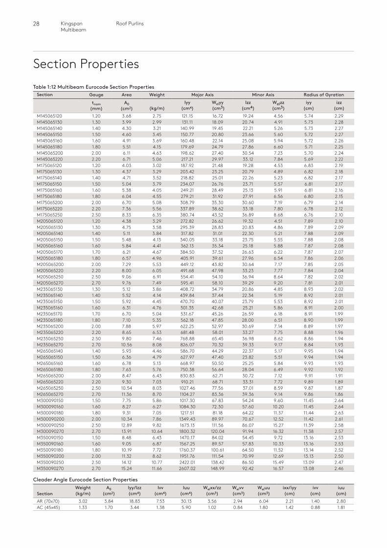
Section PropertiesTable 1:12 Multibeam Eurocode Section Properties
Section Gauge Area Weight Major Axis Minor Axis Radius of Gyration
tnom (mm)
A0 (cm2)
(kg/m)
Iyy (cm4)
Welyy (cm3)
Izz (cm4)
Welzz (cm3)
iyy (cm)
izz (cm)
M145065120 1.20 3.68 2.75 121.15 16.72 19.24 4.56 5.74 2.29M145065130 1.30 3.99 2.99 131.11 18.09 20.74 4.91 5.73 2.28M145065140 1.40 4.30 3.21 140.99 19.45 22.21 5.26 5.73 2.27M145065150 1.50 4.60 3.45 150.77 20.80 23.66 5.60 5.72 2.27M145065160 1.60 4.91 3.69 160.48 22.14 25.08 5.94 5.72 2.26M145065180 1.80 5.51 4.15 179.69 24.79 27.86 6.60 5.71 2.25M145065200 2.00 6.11 4.63 198.62 27.40 30.54 7.23 5.70 2.24M145065220 2.20 6.71 5.06 217.21 29.97 33.12 7.84 5.69 2.22M175065120 1.20 4.03 3.02 187.92 21.48 19.28 4.53 6.83 2.19M175065130 1.30 4.37 3.29 203.42 23.25 20.79 4.89 6.82 2.18M175065140 1.40 4.71 3.52 218.82 25.01 22.26 5.23 6.82 2.17M175065150 1.50 5.04 3.79 234.07 26.76 23.71 5.57 6.81 2.17M175065160 1.60 5.38 4.05 249.21 28.49 25.13 5.91 6.81 2.16M175065180 1.80 6.04 4.55 279.21 31.92 27.91 6.56 6.80 2.15M175065200 2.00 6.70 5.08 308.79 35.30 30.60 7.19 6.79 2.14M175065220 2.20 7.36 5.56 337.89 38.62 33.18 7.80 6.78 2.12M175065250 2.50 8.33 6.35 380.74 43.52 36.89 8.68 6.76 2.10M205065120 1.20 4.38 3.29 272.82 26.62 19.32 4.51 7.89 2.10M205065130 1.30 4.75 3.58 295.39 28.83 20.83 4.86 7.89 2.09M205065140 1.40 5.11 3.84 317.82 31.01 22.30 5.21 7.88 2.09M205065150 1.50 5.48 4.13 340.05 33.18 23.75 5.55 7.88 2.08M205065160 1.60 5.84 4.41 362.13 35.34 25.18 5.88 7.87 2.08M205065170 1.70 6.21 4.67 384.50 37.52 26.63 6.22 7.87 2.07M205065180 1.80 6.57 4.96 405.91 39.61 27.96 6.54 7.86 2.06M205065200 2.00 7.29 5.53 449.12 43.82 30.64 7.17 7.85 2.05M205065220 2.20 8.00 6.05 491.68 47.98 33.23 7.77 7.84 2.04M205065250 2.50 9.06 6.91 554.41 54.10 36.94 8.64 7.82 2.02M205065270 2.70 9.76 7.49 595.41 58.10 39.29 9.20 7.81 2.01M235065130 1.30 5.12 3.86 408.72 34.79 20.86 4.85 8.93 2.02M235065140 1.40 5.52 4.14 439.84 37.44 22.34 5.19 8.92 2.01M235065150 1.50 5.92 4.45 470.70 40.07 23.79 5.53 8.92 2.01M235065160 1.60 6.31 4.76 501.35 42.68 25.21 5.86 8.91 2.00M235065170 1.70 6.70 5.04 531.67 45.26 26.59 6.18 8.91 1.99M235065180 1.80 7.10 5.35 562.18 47.85 28.00 6.51 8.90 1.99M235065200 2.00 7.88 5.97 622.25 52.97 30.69 7.14 8.89 1.97M235065220 2.20 8.65 6.53 681.48 58.01 33.27 7.75 8.88 1.96M235065250 2.50 9.80 7.46 768.88 65.45 36.98 8.62 8.86 1.94M235065270 2.70 10.56 8.08 826.07 70.32 39.33 9.17 8.84 1.93M265065140 1.40 5.93 4.46 586.70 44.29 22.37 5.17 9.95 1.94M265065150 1.50 6.36 4.79 627.97 47.40 23.82 5.51 9.94 1.94M265065160 1.60 6.78 5.13 668.97 50.50 25.25 5.84 9.93 1.93M265065180 1.80 7.63 5.76 750.38 56.64 28.04 6.49 9.92 1.92M265065200 2.00 8.47 6.43 830.83 62.71 30.72 7.12 9.91 1.91M265065220 2.20 9.30 7.03 910.21 68.71 33.31 7.72 9.89 1.89M265065250 2.50 10.54 8.03 1027.46 77.56 37.01 8.59 9.87 1.87M265065270 2.70 11.36 8.70 1104.27 83.36 39.36 9.14 9.86 1.86M300090150 1.50 7.75 5.86 1017.30 67.83 54.24 9.60 11.45 2.64M300090160 1.60 8.27 6.27 1084.30 72.30 57.60 10.20 11.45 2.64M300090180 1.80 9.31 7.05 1217.51 81.18 64.22 11.37 11.44 2.63M300090200 2.00 10.34 7.86 1349.43 89.97 70.67 12.52 11.42 2.61M300090250 2.50 12.89 9.82 1673.13 111.56 86.07 15.27 11.39 2.58M300090270 2.70 13.91 10.64 1800.32 120.04 91.94 16.32 11.38 2.57M350090150 1.50 8.48 6.43 1470.17 84.02 54.45 9.72 13.16 2.53M350090160 1.60 9.05 6.87 1567.25 89.57 57.83 10.33 13.16 2.53M350090180 1.80 10.19 7.72 1760.37 100.61 64.50 11.52 13.14 2.52M350090200 2.00 11.32 8.62 1951.76 111.54 70.99 12.69 13.13 2.50M350090250 2.50 14.12 10.77 2422.01 138.42 86.50 15.49 13.09 2.47M350090270 2.70 15.24 11.66 2607.02 148.99 92.42 16.57 13.08 2.46
Cleader Angle Eurocode Section Properties
SectionWeight (kg/m)
A0 (cm2)
lyy/Izz (cm4)
Ivv (cm4)
Iuu (cm4)
Welxx/zz (cm3)
Welvv (cm3)
Weluu (cm3)
ixx/iyy (cm)
ivv (cm)
iuu (cm)
AR (70x70) 3.02 3.84 18.83 7.53 30.13 3.56 2.94 6.04 2.21 1.40 2.80AC (45x45) 1.33 1.70 3.44 1.38 5.90 1.02 0.84 1.80 1.42 0.88 1.81
29 Roof Purlins Kingspan Multibeam
Roof
Pur
lins
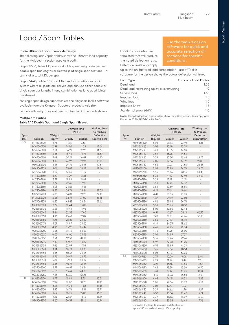
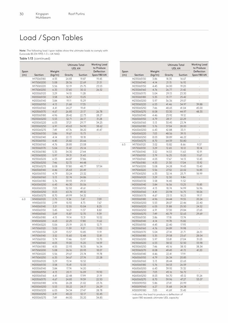
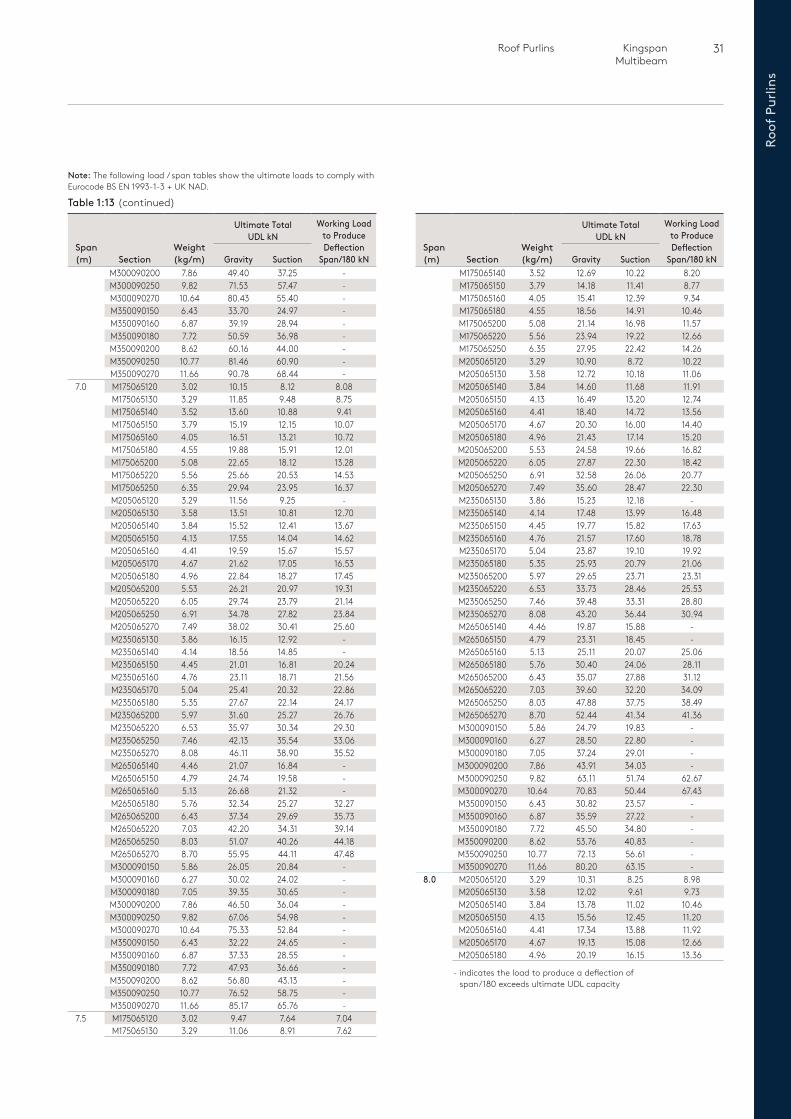
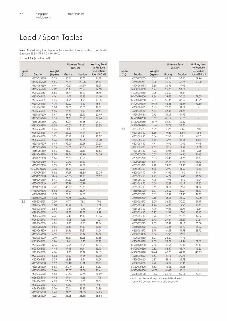
Load / Span TablesPurlin Ultimate Loads: Eurocode DesignThe following load / span tables show the ultimate load capacity for the Multibeam section used as a purlin.
Pages 29-33, Table 1:13, are for double span design using either double span bar lengths or sleeved joint single span sections – in terms of a total UDL per span.
Pages 34-43, Tables 1:15 and 1:16, are for a continuous purlin system where all joints are sleeved and can use either double or single span bar lengths in any combination as long as all joints are sleeved.
For single span design capacities use the Kingspan Toolkit software available from the Kingspan Structural products web site.
Section self-weight has not been subtracted in the loads shown.
Table 1:13 Double Span and Single Span SleevedMultibeam Purlins
- indicates the load to produce a deflection of span / 180 exceeds ultimate UDL capacity
Span (m) Section
Weight (kg/m)
Ultimate Total UDL kN
Working Load to Produce Deflection
Span/180 kNGravity SuctionM145065220 5.06 29.93 23.94 18.31M175065120 3.02 13.48 10.79 -M175065130 3.29 15.85 12.68 -M175065140 3.52 18.28 14.63 -M175065150 3.79 20.50 16.40 19.73M175065160 4.05 22.36 17.89 21.00M175065180 4.55 27.07 21.66 23.53M175065200 5.08 30.96 24.76 26.02M175065220 5.56 35.16 28.13 28.48M175065250 6.35 41.17 32.94 32.09M205065120 3.29 15.19 12.15 -M205065130 3.58 17.90 14.32 -M205065140 3.84 20.69 16.55 -M205065150 4.13 23.51 18.81 -M205065160 4.41 26.35 21.08 -M205065170 4.67 29.19 23.02 -M205065180 4.96 30.92 24.74 -M205065200 5.53 35.65 28.52 -M205065220 6.05 40.60 32.48 -M205065250 6.91 47.67 38.13 46.72M205065270 7.49 52.21 41.76 50.18M235065130 3.86 21.17 16.94 -M235065140 4.14 24.53 19.62 -M235065150 4.45 27.93 22.34 -M235065160 4.76 31.25 25.00 -M235065170 5.04 34.09 27.27 -M235065180 5.35 37.26 29.65 -M235065200 5.97 42.78 34.20 -M235065220 6.53 48.89 41.25 -M235065250 7.46 57.54 48.54 -M235065270 8.08 63.13 53.26 -
5.5 M145065120 2.75 10.08 8.06 8.44M145065130 2.99 11.79 9.44 9.13M145065140 3.21 13.58 10.86 9.82M145065150 3.45 15.38 12.30 10.50M145065160 3.69 17.19 13.75 11.18M145065180 4.15 20.76 16.60 12.52M145065200 4.63 24.15 19.32 13.83M145065220 5.06 27.36 21.89 15.13M175065120 3.02 12.47 9.97 -M175065130 3.29 14.62 11.70 14.17M175065140 3.52 16.84 13.47 15.24M175065150 3.79 18.86 15.09 16.30M175065160 4.05 20.55 16.44 17.36
Span (m) Section
Weight (kg/m)
Ultimate Total UDL kN
Working Load to Produce Deflection
Span/180 kNGravity Suction4.5 M145065120 2.75 11.95 9.33 -
M145065130 2.99 14.04 11.23 13.64M145065140 3.21 16.21 12.96 14.67M145065150 3.45 18.40 14.72 15.69M145065160 3.69 20.61 16.49 16.70M145065180 4.15 24.96 19.97 18.70M145065200 4.63 29.10 23.28 20.67M145065220 5.06 33.02 26.42 22.60M175065120 3.02 14.66 11.73 -M175065130 3.29 17.29 13.83 -M175065140 3.52 19.98 15.99 -M175065150 3.79 22.45 17.96 -M175065160 4.05 24.52 19.61 -M175065180 4.55 29.74 23.34 29.05M175065200 5.08 34.07 27.25 32.13M175065220 5.56 38.74 31.00 35.16M175065250 6.35 45.42 36.34 39.62M205065120 3.29 16.44 13.02 -M205065130 3.58 19.44 14.98 -M205065140 3.84 22.53 17.40M205065150 4.13 25.67 19.89 -M205065160 4.41 28.82 22.40 -M205065170 4.67 31.97 24.55 -M205065180 4.96 33.90 26.47 -M205065200 5.53 39.16 30.69 -M205065220 6.05 44.66 35.08 -M205065250 6.91 52.52 41.37 -M205065270 7.49 57.57 45.42 -M235065130 3.86 22.89 17.58 -M235065140 4.14 26.61 20.35 -M235065150 4.45 30.38 23.35 -M235065160 4.76 34.07 26.73 -M235065170 5.04 37.23 28.82 -M235065180 5.35 40.75 31.47 -M235065200 5.97 46.89 36.54 -M235065220 6.53 53.69 44.28 -M235065250 7.46 63.30 52.41 -
5.0 M145065120 2.75 10.94 8.75 10.21M145065130 2.99 12.82 10.26 11.05M145065140 3.21 14.78 11.82 11.88M145065150 3.45 16.76 13.41 12.71M145065160 3.69 18.75 15.00 13.53M145065180 4.15 22.67 18.13 15.14M145065200 4.63 26.39 21.12 16.74
Use the toolkit design software for quick and accurate selection ofsections for specificconditions.
Loadings have also been tabulated that will produce the noted deflection ratio. Defection limits only apply up to the un-factored load combination – use of Toolkit software for the design shows the actual deflection achieved.
Load Type Eurocode Load FactorDead load 1.35Dead load restraining uplift or overturning 1.0Service load 1.35Imposed load 1.5Wind load 1.5Imposed Snow 1.5Accidental snow (drift) 1.0
Note: The following load / span tables show the ultimate loads to comply with Eurocode BS EN 1993-1-3 + UK NAD.
30 Roof PurlinsKingspan Multibeam
Load / Span Tables
- indicates the load to produce a deflection of span/180 exceeds ultimate UDL capacity
Span (m) Section
Weight (kg/m)
Ultimate Total UDL kN
Working Load to Produce Deflection
Span/180 kNGravity SuctionM175065180 4.55 24.83 19.87 19.45M175065200 5.08 28.36 22.69 21.51M175065220 5.56 32.19 25.75 23.53M175065250 6.35 37.65 30.12 26.52M205065120 3.29 14.10 11.28 -M205065130 3.58 16.57 13.25 -M205065140 3.84 19.11 15.29 -M205065150 4.13 21.68 17.35 -M205065160 4.41 24.27 19.41 -M205065170 4.67 26.85 21.17 26.78M205065180 4.96 28.42 22.73 28.27M205065200 5.53 32.71 26.17 31.28M205065220 6.05 37.21 29.77 34.25M205065250 6.91 43.63 34.90 38.62M205065270 7.49 47.76 38.20 41.47M235065130 3.86 19.67 15.73 -M235065140 4.14 22.72 18.18 -M235065150 4.45 25.82 20.66 -M235065160 4.76 28.85 23.08 -M235065170 5.04 31.42 25.14 -M235065180 5.35 34.30 27.44 -M235065200 5.97 39.31 31.43 -M235065220 6.53 44.87 37.86 -M235065250 7.46 52.72 44.48 -M235065270 8.08 57.80 48.77 57.54M265065140 4.46 25.63 20.49 -M265065150 4.79 30.24 23.32 -M265065160 5.13 32.74 24.86 -M265065180 5.76 39.93 29.51 -M265065200 6.43 46.30 35.06 -M265065220 7.03 52.50 41.61 -M265065250 8.03 63.76 49.32 -M265065270 8.70 69.99 54.32 -
6.0 M145065120 2.75 9.34 7.47 7.09M145065130 2.99 10.92 8.73 7.67M145065140 3.21 12.55 10.04 8.25M145065150 3.45 14.21 11.37 8.82M145065160 3.69 15.87 12.70 9.39M145065180 4.15 19.14 15.31 10.52M145065200 4.63 22.25 17.80 11.62M145065220 5.06 25.19 20.15 12.71M175065120 3.02 11.59 9.27 11.00M175065130 3.29 13.57 10.85 11.91M175065140 3.52 15.60 12.48 12.81M175065150 3.79 17.46 13.97 13.70M175065160 4.05 19.00 15.20 14.59M175065180 4.55 22.93 18.35 16.34M175065200 5.08 26.16 20.93 18.07M175065220 5.56 29.67 23.74 19.78M175065250 6.35 34.67 27.74 22.28M205065120 3.29 13.14 10.52 -M205065130 3.58 15.41 12.33 -M205065140 3.84 17.74 14.20 -M205065150 4.13 20.11 16.09 19.90M205065160 4.41 22.48 17.99 21.19M205065170 4.67 24.85 19.59 22.50M205065180 4.96 26.28 21.02 23.76M205065200 5.53 30.22 24.17 26.29M205065220 6.05 34.34 27.47 28.78M205065250 6.91 40.22 32.17 32.45M205065270 7.49 44.00 35.20 34.85
Span (m) Section
Weight (kg/m)
Ultimate Total UDL kN
Working Load to Produce Deflection
Span/180 kNGravity SuctionM235065130 3.86 18.35 14.67 -M235065140 4.14 21.15 16.92 -M235065150 4.45 24.00 19.20 -M235065160 4.76 26.77 21.42 -M235065170 5.04 29.13 23.30 -M235065180 5.35 31.77 25.42 -M235065200 5.97 36.36 29.07 -M235065220 6.53 41.46 34.97 39.88M235065250 7.46 48.65 41.04 45.00M235065270 8.08 53.30 44.97 48.35M265065140 4.46 23.92 19.12 -M265065150 4.79 28.17 22.29 -M265065160 5.13 30.45 23.74 -M265065180 5.76 37.04 28.00 -M265065200 6.43 42.88 33.11 -M265065220 7.03 48.56 39.15 -M265065250 8.03 58.89 46.22 -M265065270 8.70 64.59 50.80 -
6.5 M175065120 3.02 10.82 8.66 9.37M175065130 3.29 12.65 10.12 10.14M175065140 3.52 14.53 11.63 10.91M175065150 3.79 16.25 13.00 11.67M175065160 4.05 17.67 14.13 12.43M175065180 4.55 21.30 17.04 13.92M175065200 5.08 24.28 19.43 15.40M175065220 5.56 27.52 22.02 16.85M175065250 6.35 32.14 25.71 18.99M205065120 3.29 12.30 9.84 -M205065130 3.58 14.40 11.52 -M205065140 3.84 16.56 13.25 15.85M205065150 4.13 18.74 14.99 16.96M205065160 4.41 20.94 16.75 18.06M205065170 4.67 23.13 18.23 19.17M205065180 4.96 24.44 19.55 20.24M205065200 5.53 28.07 22.46 22.40M205065220 6.05 31.88 25.50 24.52M205065250 6.91 37.30 29.84 27.65M205065270 7.49 40.79 32.63 29.69M235065130 3.86 17.18 13.74 -M235065140 4.14 19.78 15.82 -M235065150 4.45 22.40 17.93 -M235065160 4.76 24.89 19.98 -M235065170 5.04 27.14 21.71 26.51M235065180 5.35 29.58 23.67 28.04M235065200 5.97 33.81 27.04 31.03M235065220 6.53 38.52 32.50 33.98M235065250 7.46 45.16 38.10 38.34M235065270 8.08 49.45 41.72 41.20M265065140 4.46 22.41 17.91 -M265065150 4.79 26.34 20.85 -M265065160 5.13 28.44 22.65 -M265065180 5.76 34.53 26.59 -M265065200 6.43 39.92 31.32 -M265065220 7.03 45.16 36.72 -M265065250 8.03 54.70 43.12 51.24M265065270 8.70 59.96 47.27 55.07M300090150 5.86 27.41 20.99 -M300090160 6.27 31.68 24.38 -M300090180 7.05 41.69 31.45 -
Note: The following load / span tables show the ultimate loads to comply with Eurocode BS EN 1993-1-3 + UK NAD.
Table 1:13 (continued)
31 Roof Purlins Kingspan Multibeam
Roof
Pur
lins
- indicates the load to produce a deflection of span/180 exceeds ultimate UDL capacity
Span (m) Section
Weight (kg/m)
Ultimate Total UDL kN
Working Load to Produce Deflection
Span/180 kNGravity SuctionM300090200 7.86 49.40 37.25 -M300090250 9.82 71.53 57.47 -M300090270 10.64 80.43 55.40 -M350090150 6.43 33.70 24.97 -M350090160 6.87 39.19 28.94 -M350090180 7.72 50.59 36.98 -M350090200 8.62 60.16 44.00 -M350090250 10.77 81.46 60.90 -M350090270 11.66 90.78 68.44 -
7.0 M175065120 3.02 10.15 8.12 8.08M175065130 3.29 11.85 9.48 8.75M175065140 3.52 13.60 10.88 9.41M175065150 3.79 15.19 12.15 10.07M175065160 4.05 16.51 13.21 10.72M175065180 4.55 19.88 15.91 12.01M175065200 5.08 22.65 18.12 13.28M175065220 5.56 25.66 20.53 14.53M175065250 6.35 29.94 23.95 16.37M205065120 3.29 11.56 9.25 -M205065130 3.58 13.51 10.81 12.70M205065140 3.84 15.52 12.41 13.67M205065150 4.13 17.55 14.04 14.62M205065160 4.41 19.59 15.67 15.57M205065170 4.67 21.62 17.05 16.53M205065180 4.96 22.84 18.27 17.45M205065200 5.53 26.21 20.97 19.31M205065220 6.05 29.74 23.79 21.14M205065250 6.91 34.78 27.82 23.84M205065270 7.49 38.02 30.41 25.60M235065130 3.86 16.15 12.92 -M235065140 4.14 18.56 14.85 -M235065150 4.45 21.01 16.81 20.24M235065160 4.76 23.11 18.71 21.56M235065170 5.04 25.41 20.32 22.86M235065180 5.35 27.67 22.14 24.17M235065200 5.97 31.60 25.27 26.76M235065220 6.53 35.97 30.34 29.30M235065250 7.46 42.13 35.54 33.06M235065270 8.08 46.11 38.90 35.52M265065140 4.46 21.07 16.84 -M265065150 4.79 24.74 19.58 -M265065160 5.13 26.68 21.32 -M265065180 5.76 32.34 25.27 32.27M265065200 6.43 37.34 29.69 35.73M265065220 7.03 42.20 34.31 39.14M265065250 8.03 51.07 40.26 44.18M265065270 8.70 55.95 44.11 47.48M300090150 5.86 26.05 20.84 -M300090160 6.27 30.02 24.02 -M300090180 7.05 39.35 30.65 -M300090200 7.86 46.50 36.04 -M300090250 9.82 67.06 54.98 -M300090270 10.64 75.33 52.84 -M350090150 6.43 32.22 24.65 -M350090160 6.87 37.33 28.55 -M350090180 7.72 47.93 36.66 -M350090200 8.62 56.80 43.13 -M350090250 10.77 76.52 58.75 -M350090270 11.66 85.17 65.76 -
7.5 M175065120 3.02 9.47 7.64 7.04M175065130 3.29 11.06 8.91 7.62
Span (m) Section
Weight (kg/m)
Ultimate Total UDL kN
Working Load to Produce Deflection
Span/180 kNGravity SuctionM175065140 3.52 12.69 10.22 8.20M175065150 3.79 14.18 11.41 8.77M175065160 4.05 15.41 12.39 9.34M175065180 4.55 18.56 14.91 10.46M175065200 5.08 21.14 16.98 11.57M175065220 5.56 23.94 19.22 12.66M175065250 6.35 27.95 22.42 14.26M205065120 3.29 10.90 8.72 10.22M205065130 3.58 12.72 10.18 11.06M205065140 3.84 14.60 11.68 11.91M205065150 4.13 16.49 13.20 12.74M205065160 4.41 18.40 14.72 13.56M205065170 4.67 20.30 16.00 14.40M205065180 4.96 21.43 17.14 15.20M205065200 5.53 24.58 19.66 16.82M205065220 6.05 27.87 22.30 18.42M205065250 6.91 32.58 26.06 20.77M205065270 7.49 35.60 28.47 22.30M235065130 3.86 15.23 12.18 -M235065140 4.14 17.48 13.99 16.48M235065150 4.45 19.77 15.82 17.63M235065160 4.76 21.57 17.60 18.78M235065170 5.04 23.87 19.10 19.92M235065180 5.35 25.93 20.79 21.06M235065200 5.97 29.65 23.71 23.31M235065220 6.53 33.73 28.46 25.53M235065250 7.46 39.48 33.31 28.80M235065270 8.08 43.20 36.44 30.94M265065140 4.46 19.87 15.88 -M265065150 4.79 23.31 18.45 -M265065160 5.13 25.11 20.07 25.06M265065180 5.76 30.40 24.06 28.11M265065200 6.43 35.07 27.88 31.12M265065220 7.03 39.60 32.20 34.09M265065250 8.03 47.88 37.75 38.49M265065270 8.70 52.44 41.34 41.36M300090150 5.86 24.79 19.83 -M300090160 6.27 28.50 22.80 -M300090180 7.05 37.24 29.01 -M300090200 7.86 43.91 34.03 -M300090250 9.82 63.11 51.74 62.67M300090270 10.64 70.83 50.44 67.43M350090150 6.43 30.82 23.57 -M350090160 6.87 35.59 27.22 -M350090180 7.72 45.50 34.80 -M350090200 8.62 53.76 40.83 -M350090250 10.77 72.13 56.61 -M350090270 11.66 80.20 63.15 -
8.0 M205065120 3.29 10.31 8.25 8.98M205065130 3.58 12.02 9.61 9.73M205065140 3.84 13.78 11.02 10.46M205065150 4.13 15.56 12.45 11.20M205065160 4.41 17.34 13.88 11.92M205065170 4.67 19.13 15.08 12.66M205065180 4.96 20.19 16.15 13.36
Note: The following load / span tables show the ultimate loads to comply with Eurocode BS EN 1993-1-3 + UK NAD.
Table 1:13 (continued)
32 Roof PurlinsKingspan Multibeam
Load / Span Tables
- indicates the load to produce a deflection of span/180 exceeds ultimate UDL capacity
Span (m) Section
Weight (kg/m)
Ultimate Total UDL kN
Working Load to Produce Deflection
Span/180 kNGravity SuctionM205065200 5.53 23.14 18.51 14.79M205065220 6.05 26.23 20.98 16.19M205065250 6.91 30.63 24.50 18.25M205065270 7.49 33.47 26.77 19.60M235065130 3.86 14.41 11.52 13.46M235065140 4.14 16.52 13.22 14.48M235065150 4.45 18.66 14.93 15.50M235065160 4.76 20.22 16.60 16.51M235065170 5.04 22.52 18.01 17.50M235065180 5.35 24.31 19.60 18.51M235065200 5.97 27.93 22.33 20.49M235065220 6.53 31.75 26.79 22.44M235065250 7.46 37.14 31.33 25.31M235065270 8.08 40.63 34.27 27.20M265065140 4.46 18.80 15.03 -M265065150 4.79 22.03 17.44 20.67M265065160 5.13 23.72 18.96 22.02M265065180 5.76 28.68 22.95 24.70M265065200 6.43 33.05 26.28 27.35M265065220 7.03 37.31 30.33 29.97M265065250 8.03 45.07 35.53 33.83M265065270 8.70 49.34 38.90 36.35M300090150 5.86 23.63 18.91 -M300090160 6.27 27.12 21.69 -M300090180 7.05 35.33 27.52 -M300090200 7.86 41.58 32.23 -M300090250 9.82 59.59 48.85 55.08M300090270 10.64 66.83 48.21 59.27M350090150 6.43 29.50 22.56 -M350090160 6.87 33.98 25.98 -M350090180 7.72 43.29 33.11 -M350090200 8.62 51.02 38.74 -M350090250 10.77 68.21 54.52 -M350090270 11.66 75.76 60.66 -
8.5 M205065120 3.29 9.77 7.82 7.96M205065130 3.58 11.39 9.11 8.61M205065140 3.84 13.04 10.43 9.27M205065150 4.13 14.72 11.78 9.92M205065160 4.41 16.40 13.12 10.56M205065170 4.67 18.08 14.26 11.21M205065180 4.96 19.08 15.26 11.84M205065200 5.53 21.85 17.48 13.10M205065220 6.05 24.76 19.81 14.34M205065250 6.91 28.91 23.12 16.17M205065270 7.49 31.57 25.26 17.36M235065130 3.86 13.66 10.93 11.92M235065140 4.14 15.66 12.53 12.83M235065150 4.45 17.68 14.14 13.73M235065160 4.76 19.03 15.72 14.62M235065170 5.04 21.30 17.04 15.50M235065180 5.35 22.88 18.54 16.39M235065200 5.97 26.40 21.11 18.15M235065220 6.53 29.99 25.31 19.87M235065250 7.46 35.07 29.58 22.42M235065270 8.08 38.34 32.35 24.09M265065140 4.46 17.84 14.26 17.11M265065150 4.79 20.88 16.53 18.31M265065160 5.13 22.47 17.96 19.51M265065180 5.76 27.14 21.89 21.88M265065200 6.43 31.26 24.85 24.23M265065220 7.03 35.26 28.66 26.54
Span (m) Section
Weight (kg/m)
Ultimate Total UDL kN
Working Load to Produce Deflection
Span/180 kNGravity SuctionM265065250 8.03 42.57 33.56 29.96M265065270 8.70 46.59 36.73 32.20M300090150 5.86 22.56 18.05 -M300090160 6.27 25.85 20.68 -M300090180 7.05 33.60 26.17 -M300090200 7.86 39.48 30.60 39.35M300090250 9.82 56.43 46.27 48.79M300090270 10.64 63.25 46.14 52.50M350090150 6.43 28.26 21.61 -M350090160 6.87 32.48 24.84 -M350090180 7.72 41.25 31.55 -M350090200 8.62 48.52 36.85 -M350090250 10.77 64.67 52.52 -M350090270 11.66 71.78 58.30 -
9.0 M205065120 3.29 9.29 7.44 7.10M205065130 3.58 10.82 8.65 7.68M205065140 3.84 12.38 9.91 8.27M205065150 4.13 13.97 11.18 8.85M205065160 4.41 15.56 12.45 9.42M205065170 4.67 17.15 13.52 10.00M205065180 4.96 18.08 14.47 10.56M205065200 5.53 20.70 16.56 11.68M205065220 6.05 23.45 18.76 12.79M205065250 6.91 27.37 21.89 14.42M205065270 7.49 29.88 23.90 15.49M235065130 3.86 12.99 10.39 10.63M235065140 4.14 14.88 11.90 11.44M235065150 4.45 16.79 13.43 12.24M235065160 4.76 17.98 14.92 13.04M235065170 5.04 20.21 16.17 13.83M235065180 5.35 21.61 17.58 14.62M235065200 5.97 25.02 20.01 16.19M235065220 6.53 28.42 23.98 17.73M235065250 7.46 33.21 28.02 20.00M235065270 8.08 36.30 30.63 21.49M265065140 4.46 16.97 13.56 15.26M265065150 4.79 19.85 15.71 16.34M265065160 5.13 21.34 17.06 17.40M265065180 5.76 25.76 20.78 19.52M265065200 6.43 29.64 23.57 21.61M265065220 7.03 33.42 27.17 23.68M265065250 8.03 40.33 31.79 26.73M265065270 8.70 44.12 34.78 28.72M300090150 5.86 21.58 17.26 -M300090160 6.27 24.69 19.75 -M300090180 7.05 32.02 24.94 31.67M300090200 7.86 37.57 29.12 35.10M300090250 9.82 53.59 43.94 43.52M300090270 10.64 60.03 44.22 46.83M350090150 6.43 27.10 20.73 -M350090160 6.87 31.10 23.78 -M350090180 7.72 39.39 30.13 -M350090200 8.62 46.25 35.13 -M350090250 10.77 61.48 50.61 -M350090270 11.66 68.20 56.08 67.81
Note: The following load / span tables show the ultimate loads to comply with Eurocode BS EN 1993-1-3 + UK NAD.
Table 1:13 (continued)
33 Roof Purlins Kingspan Multibeam
Roof
Pur
lins
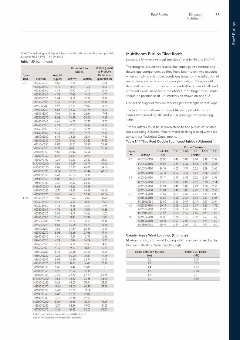
Multibeam Purlins Tiled RoofsLoads are Ultimate vertical (on slope) and in kN and kN/m2.
The designer should not resolve the loadings into normal and downslope components as they have been taken into account when compiling this table. Loads are based on the utilisation of an anti-sag system comprising angle struts at 1/3 span with diagonal rod ties at a minimum slope to the purlins of 30º and stiffened cleats. In order to maintain 30º on larger bays, struts should be positioned at 1/4 intervals as shown on page 16.
One set of diagonal rods are required per 6m length of roof slope.
The load / spans shown in Table 1:14 are applicable to roof slopes not exceeding 30º and purlin spacings not exceeding 1.8m.
Timber rafters must be securely fixed to the purlins at centres not exceeding 600mm. Where metal decking is used with tiles consult our Technical Department.
Span (m) Section
Weight (kg/m)
Ultimate Total UDL kN
Working Load to Produce Deflection
Span/180 kNGravity Suction9.5 M235065130 3.86 12.31 9.91 9.54
M235065140 4.14 14.10 11.34 10.27M235065150 4.45 15.90 12.79 10.99M235065160 4.76 17.03 14.20 11.70M235065170 5.04 19.14 15.38 12.41M235065180 5.35 20.47 16.72 13.12M235065200 5.97 23.70 19.02 14.53M235065220 6.53 26.92 22.78 15.91M235065250 7.46 31.46 26.61 17.95M235065270 8.08 34.39 29.08 19.29M265065140 4.46 16.07 12.93 13.70M265065150 4.79 18.81 14.97 14.66M265065160 5.13 20.22 16.24 15.62M265065180 5.76 24.41 19.77 17.52M265065200 6.43 28.08 22.41 19.40M265065220 7.03 31.66 25.83 21.25M265065250 8.03 38.21 30.20 23.99M265065270 8.70 41.80 33.04 25.78M300090150 5.86 20.44 16.54 -M300090160 6.27 23.39 18.90 -M300090180 7.05 30.33 23.82 28.42M300090200 7.86 35.59 27.77 31.50M300090250 9.82 50.77 41.83 39.06M300090270 10.64 56.87 42.44 42.03M350090150 6.43 26.03 19.91 -M350090160 6.87 29.81 22.80 -M350090180 7.72 37.32 28.82 -M350090200 8.62 43.82 33.55 -M350090250 10.77 58.25 48.80 56.54M350090270 11.66 64.61 53.98 60.86
10.0 M235065130 3.86 11.69 9.46 8.61M235065140 4.14 13.39 10.82 9.27M235065150 4.45 15.11 12.20 9.92M235065160 4.76 16.18 13.54 10.56M235065170 5.04 18.19 14.66 11.20M235065180 5.35 19.45 15.94 11.85M235065200 5.97 22.52 18.12 13.11M235065220 6.53 25.58 21.70 14.36M235065250 7.46 29.89 25.33 16.20M235065270 8.08 32.68 27.68 17.41M265065140 4.46 15.27 12.35 12.36M265065150 4.79 17.87 14.29 13.23M265065160 5.13 19.21 15.50 14.10M265065180 5.76 23.19 18.85 15.81M265065200 6.43 26.68 21.36 17.51M265065220 7.03 30.08 24.61 19.18M265065250 8.03 36.30 28.77 21.65M265065270 8.70 39.71 31.46 23.27M300090150 5.86 19.42 15.86 -M300090160 6.27 22.22 18.11 -M300090180 7.05 28.82 22.79 25.65M300090200 7.86 33.82 26.55 28.43M300090250 9.82 48.23 39.91 35.25M300090270 10.64 54.03 40.78 37.93M350090150 6.43 25.02 19.14 -M350090160 6.87 28.62 21.89 -M350090180 7.72 35.45 27.62 -M350090200 8.62 41.63 32.11 41.12M350090250 10.77 55.34 47.09 51.03M350090270 11.66 61.38 52.02 54.93
Cleader Angle Wind Loadings (Ultimate)Maximum horizontal wind loading which can be carried by the Kingspan 70x70x2.7mm cleader angle.
Span Between Purlins (m)
Total UDL (wind) (kN)
1.0 3.781.2 3.171.4 2.731.6 2.381.8 2.112.0 1.90
Span (m) Section
Total UDL kN
Purlin Centres m1.2 1.375 1.5 1.675 1.8
kN/m25.0 M205065150 20.85 3.48 3.03 2.78 2.49 2.32
M205065160 23.06 3.84 3.35 3.08 2.75 2.56M205065180 24.14 4.02 3.51 3.22 2.88 2.68M235065160 24.14 4.02 3.51 3.22 2.88 2.68
5.5 M205065150 19.17 2.90 2.53 2.32 2.08 2.08M205065160 21.17 3.21 2.80 2.57 2.30 2.14M235065160 23.04 3.49 3.05 2.79 2.50 2.33M235065180 23.04 3.49 3.05 2.79 2.50 2.33
6.0 M235065160 21.65 3.01 2.62 2.41 2.15 2.00M235065180 22.00 3.06 2.67 2.44 2.19 2.04M235065200 22.00 3.06 2.67 2.44 2.19 2.04
6.5 M235065160 20.13 2.58 2.25 2.07 1.85 1.72M235065180 21.02 2.69 2.35 2.16 1.93 1.80M235065200 21.02 2.69 2.35 2.16 1.93 1.80
7.0 M235065160 18.81 2.24 1.95 1.79 1.60 1.49M235065180 20.10 2.39 2.09 1.91 1.71 1.60M235065200 20.10 2.39 2.09 1.91 1.71 1.60
Table 1:14 Tiled Roof Double Span Load Tables (Ultimate)
- indicates the load to produce a deflection of span/180 exceeds ultimate UDL capacity
Note: The following load / span tables show the ultimate loads to comply with Eurocode BS EN 1993-1-3 + UK NAD.
Table 1:13 (continued)
34 Roof PurlinsKingspan Multibeam
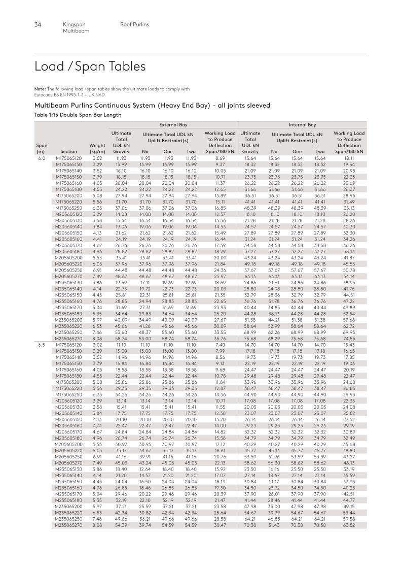
Load / Span Tables
Multibeam Purlins Continuous System (Heavy End Bay) - all joints sleevedTable 1:15 Double Span Bar Length
Span (m) Section
Weight (kg/m)
External Bay Internal Bay
Ultimate Total
UDL kNGravity
Ultimate Total UDL kN Uplift Restraint(s)
Working Load to Produce Deflection
Span/180 kN
Ultimate Total
UDL kNGravity
Ultimate Total UDL kN Uplift Restraint(s)
Working Load to Produce Deflection
Span/180 kNNo One Two No One Two6.0 M175065120 3.02 11.93 11.93 11.93 11.93 8.69 15.64 15.64 15.64 15.64 18.11
M175065130 3.29 13.99 13.99 13.99 13.99 9.37 18.32 18.32 18.32 18.32 19.54M175065140 3.52 16.10 16.10 16.10 16.10 10.05 21.09 21.09 21.09 21.09 20.95M175065150 3.79 18.15 18.15 18.15 18.15 10.71 23.75 23.75 23.75 23.75 22.33M175065160 4.05 20.04 20.04 20.04 20.04 11.37 26.22 26.22 26.22 26.22 23.69M175065180 4.55 24.22 24.22 24.22 24.22 12.65 31.66 31.66 31.66 31.66 26.37M175065200 5.08 27.94 27.94 27.94 27.94 13.89 36.51 36.51 36.51 36.51 28.96M175065220 5.56 31.70 31.70 31.70 31.70 15.11 41.41 41.41 41.41 41.41 31.49M175065250 6.35 37.06 37.06 37.06 37.06 16.85 48.39 48.39 48.39 48.39 35.13M205605120 3.29 14.08 14.08 14.08 14.08 12.57 18.10 18.10 18.10 18.10 26.20M205605130 3.58 16.54 16.54 16.54 16.54 13.56 21.28 21.28 21.28 21.28 28.26M205605140 3.84 19.06 19.06 19.06 19.06 14.53 24.57 24.57 24.57 24.57 30.30M205605150 4.13 21.62 21.62 21.62 21.62 15.49 27.89 27.89 27.89 27.89 32.30M205605160 4.41 24.19 24.19 24.19 24.19 16.44 31.24 31.24 31.24 31.24 34.26M205605170 4.67 26.76 26.76 26.76 26.76 17.39 34.58 34.58 34.58 34.58 36.26M205605180 4.96 28.82 28.82 28.82 28.82 18.29 37.27 37.27 37.27 37.27 38.13M205605200 5.53 33.41 33.41 33.41 33.41 20.09 43.24 43.24 43.24 43.24 41.87M205605220 6.05 37.96 37.96 37.96 37.96 21.84 49.18 49.18 49.18 49.18 45.53M205605250 6.91 44.48 44.48 44.48 44.48 24.36 57.67 57.67 57.67 57.67 50.78M205605270 7.49 48.67 48.67 48.67 48.67 25.97 63.13 63.13 63.13 63.13 54.14M235065130 3.86 19.69 17.11 19.69 19.69 18.69 24.86 21.61 24.86 24.86 38.95M235065140 4.14 22.73 19.72 22.73 22.73 20.03 28.80 24.98 28.80 28.80 41.76M235065150 4.45 25.81 22.31 25.81 25.81 21.35 32.79 28.36 32.79 32.79 44.51M235065160 4.76 28.85 24.94 28.85 28.85 22.65 36.76 31.78 36.76 36.76 47.22M235065170 5.04 31.69 27.31 31.69 31.69 23.93 40.44 34.85 40.44 40.44 49.89M235065180 5.35 34.64 29.83 34.64 34.64 25.20 44.28 38.13 44.28 44.28 52.54M235065200 5.97 40.09 34.49 40.09 40.09 27.67 51.38 44.21 51.38 51.38 57.68M235065220 6.53 45.66 41.26 45.66 45.66 30.09 58.64 52.99 58.64 58.64 62.72M235065250 7.46 53.60 48.37 53.60 53.60 33.55 68.99 62.26 68.99 68.99 69.93M235065270 8.08 58.74 53.00 58.74 58.74 35.76 75.68 68.29 75.68 75.68 74.55
6.5 M175065120 3.02 11.10 11.10 11.10 11.10 7.40 14.70 14.70 14.70 14.70 15.43M175065130 3.29 13.00 13.00 13.00 13.00 7.99 17.18 17.18 17.18 17.18 16.65M175065140 3.52 14.96 14.96 14.96 14.96 8.56 19.73 19.73 19.73 19.73 17.85M175065150 3.79 16.84 16.84 16.84 16.84 9.13 22.19 22.19 22.19 22.19 19.03M175065160 4.05 18.58 18.58 18.58 18.58 9.68 24.47 24.47 24.47 24.47 20.19M175065180 4.55 22.44 22.44 22.44 22.44 10.78 29.48 29.48 29.48 29.48 22.47M175065200 5.08 25.86 25.86 25.86 25.86 11.84 33.96 33.96 33.96 33.96 24.68M175065220 5.56 29.33 29.33 29.33 29.33 12.87 38.47 38.47 38.47 38.47 26.83M175065250 6.35 34.26 34.26 34.26 34.26 14.36 44.90 44.90 44.90 44.90 29.93M205605120 3.29 13.14 13.14 13.14 13.14 10.71 17.08 17.08 17.08 17.08 22.33M205605130 3.58 15.41 15.41 15.41 15.41 11.55 20.03 20.03 20.03 20.03 24.08M205605140 3.84 17.75 17.75 17.75 17.75 12.38 23.07 23.07 23.07 23.07 25.82M205605150 4.13 20.10 20.10 20.10 20.10 13.20 26.14 26.14 26.14 26.14 27.52M205605160 4.41 22.47 22.47 22.47 22.47 14.00 29.23 29.23 29.23 29.23 29.19M205605170 4.67 24.84 24.84 24.84 24.84 14.82 32.32 32.32 32.32 32.32 30.89M205605180 4.96 26.74 26.74 26.74 26.74 15.58 34.79 34.79 34.79 34.79 32.49M205605200 5.53 30.97 30.95 30.97 30.97 17.12 40.29 40.27 40.29 40.29 35.68M205605220 6.05 35.17 34.67 35.17 35.17 18.61 45.77 45.13 45.77 45.77 38.80M205605250 6.91 41.16 39.91 41.16 41.16 20.76 53.59 51.96 53.59 53.59 43.27M205605270 7.49 45.03 43.24 45.03 45.03 22.13 58.62 56.30 58.62 58.62 46.13M235065130 3.86 18.40 12.64 18.40 18.40 15.92 23.50 16.16 23.50 23.50 33.19M235065140 4.14 21.20 14.57 21.20 21.20 17.07 27.14 18.67 27.14 27.14 35.59M235065150 4.45 24.04 16.50 24.04 24.04 18.19 30.84 21.17 30.84 30.84 37.93M235065160 4.76 26.85 18.46 26.85 26.85 19.30 34.50 23.72 34.50 34.50 40.23M235065170 5.04 29.46 20.22 29.46 29.46 20.39 37.90 26.01 37.90 37.90 42.51M235065180 5.35 32.19 22.10 32.19 32.19 21.47 41.44 28.46 41.44 41.44 44.77M235065200 5.97 37.21 25.59 37.21 37.21 23.58 47.98 33.00 47.98 47.98 49.15M235065220 6.53 42.34 30.82 42.34 42.34 25.64 54.67 39.79 54.67 54.67 53.44M235065250 7.46 49.66 36.21 49.66 49.66 28.58 64.21 46.83 64.21 64.21 59.58M235065270 8.08 54.39 39.74 54.39 54.39 30.47 70.38 51.43 70.38 70.38 63.52
Note: The following load / span tables show the ultimate loads to comply with Eurocode BS EN 1993-1-3 + UK NAD.
35 Roof Purlins Kingspan Multibeam
Roof
Pur
lins
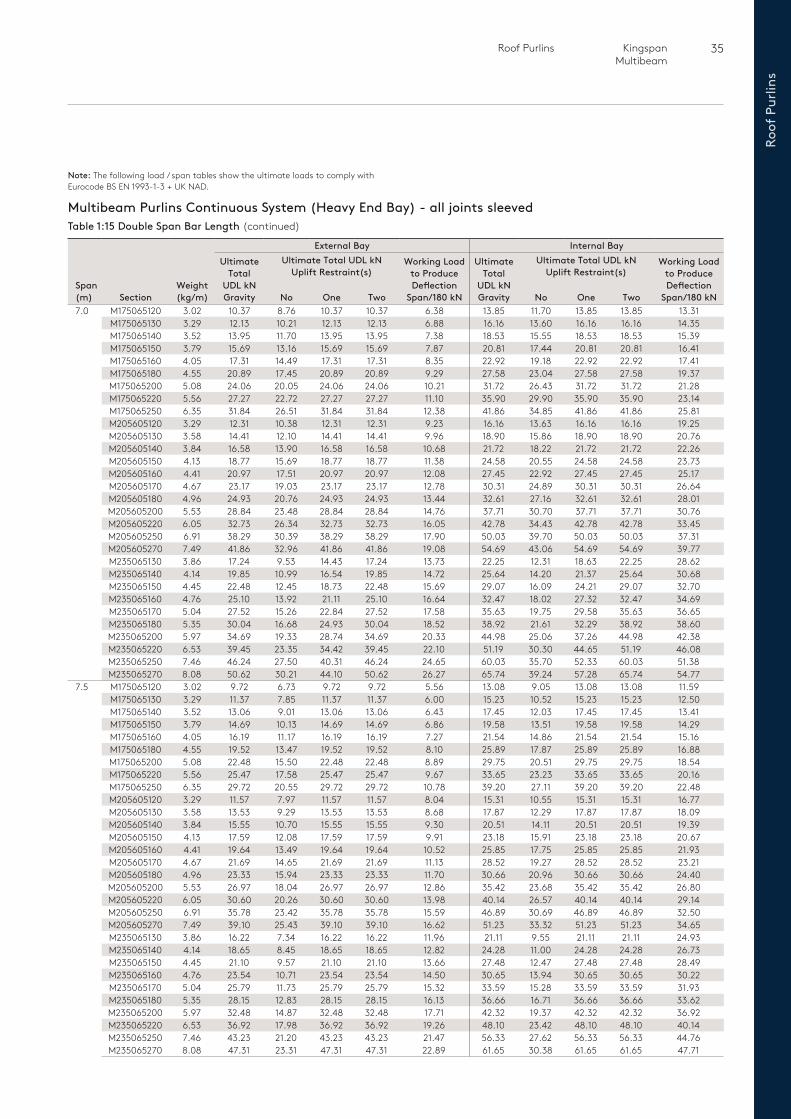
Multibeam Purlins Continuous System (Heavy End Bay) - all joints sleevedTable 1:15 Double Span Bar Length (continued)
Span (m) Section
Weight (kg/m)
External Bay Internal Bay Ultimate
Total UDL kNGravity
Ultimate Total UDL kN Uplift Restraint(s)
Working Load to Produce Deflection
Span/180 kN
Ultimate Total
UDL kNGravity
Ultimate Total UDL kN Uplift Restraint(s)
Working Load to Produce Deflection
Span/180 kNNo One Two No One Two7.0 M175065120 3.02 10.37 8.76 10.37 10.37 6.38 13.85 11.70 13.85 13.85 13.31
M175065130 3.29 12.13 10.21 12.13 12.13 6.88 16.16 13.60 16.16 16.16 14.35M175065140 3.52 13.95 11.70 13.95 13.95 7.38 18.53 15.55 18.53 18.53 15.39M175065150 3.79 15.69 13.16 15.69 15.69 7.87 20.81 17.44 20.81 20.81 16.41M175065160 4.05 17.31 14.49 17.31 17.31 8.35 22.92 19.18 22.92 22.92 17.41M175065180 4.55 20.89 17.45 20.89 20.89 9.29 27.58 23.04 27.58 27.58 19.37M175065200 5.08 24.06 20.05 24.06 24.06 10.21 31.72 26.43 31.72 31.72 21.28M175065220 5.56 27.27 22.72 27.27 27.27 11.10 35.90 29.90 35.90 35.90 23.14M175065250 6.35 31.84 26.51 31.84 31.84 12.38 41.86 34.85 41.86 41.86 25.81M205605120 3.29 12.31 10.38 12.31 12.31 9.23 16.16 13.63 16.16 16.16 19.25M205605130 3.58 14.41 12.10 14.41 14.41 9.96 18.90 15.86 18.90 18.90 20.76M205605140 3.84 16.58 13.90 16.58 16.58 10.68 21.72 18.22 21.72 21.72 22.26M205605150 4.13 18.77 15.69 18.77 18.77 11.38 24.58 20.55 24.58 24.58 23.73M205605160 4.41 20.97 17.51 20.97 20.97 12.08 27.45 22.92 27.45 27.45 25.17M205605170 4.67 23.17 19.03 23.17 23.17 12.78 30.31 24.89 30.31 30.31 26.64M205605180 4.96 24.93 20.76 24.93 24.93 13.44 32.61 27.16 32.61 32.61 28.01M205605200 5.53 28.84 23.48 28.84 28.84 14.76 37.71 30.70 37.71 37.71 30.76M205605220 6.05 32.73 26.34 32.73 32.73 16.05 42.78 34.43 42.78 42.78 33.45M205605250 6.91 38.29 30.39 38.29 38.29 17.90 50.03 39.70 50.03 50.03 37.31M205605270 7.49 41.86 32.96 41.86 41.86 19.08 54.69 43.06 54.69 54.69 39.77M235065130 3.86 17.24 9.53 14.43 17.24 13.73 22.25 12.31 18.63 22.25 28.62M235065140 4.14 19.85 10.99 16.54 19.85 14.72 25.64 14.20 21.37 25.64 30.68M235065150 4.45 22.48 12.45 18.73 22.48 15.69 29.07 16.09 24.21 29.07 32.70M235065160 4.76 25.10 13.92 21.11 25.10 16.64 32.47 18.02 27.32 32.47 34.69M235065170 5.04 27.52 15.26 22.84 27.52 17.58 35.63 19.75 29.58 35.63 36.65M235065180 5.35 30.04 16.68 24.93 30.04 18.52 38.92 21.61 32.29 38.92 38.60M235065200 5.97 34.69 19.33 28.74 34.69 20.33 44.98 25.06 37.26 44.98 42.38M235065220 6.53 39.45 23.35 34.42 39.45 22.10 51.19 30.30 44.65 51.19 46.08M235065250 7.46 46.24 27.50 40.31 46.24 24.65 60.03 35.70 52.33 60.03 51.38M235065270 8.08 50.62 30.21 44.10 50.62 26.27 65.74 39.24 57.28 65.74 54.77
7.5 M175065120 3.02 9.72 6.73 9.72 9.72 5.56 13.08 9.05 13.08 13.08 11.59M175065130 3.29 11.37 7.85 11.37 11.37 6.00 15.23 10.52 15.23 15.23 12.50M175065140 3.52 13.06 9.01 13.06 13.06 6.43 17.45 12.03 17.45 17.45 13.41M175065150 3.79 14.69 10.13 14.69 14.69 6.86 19.58 13.51 19.58 19.58 14.29M175065160 4.05 16.19 11.17 16.19 16.19 7.27 21.54 14.86 21.54 21.54 15.16M175065180 4.55 19.52 13.47 19.52 19.52 8.10 25.89 17.87 25.89 25.89 16.88M175065200 5.08 22.48 15.50 22.48 22.48 8.89 29.75 20.51 29.75 29.75 18.54M175065220 5.56 25.47 17.58 25.47 25.47 9.67 33.65 23.23 33.65 33.65 20.16M175065250 6.35 29.72 20.55 29.72 29.72 10.78 39.20 27.11 39.20 39.20 22.48M205605120 3.29 11.57 7.97 11.57 11.57 8.04 15.31 10.55 15.31 15.31 16.77M205605130 3.58 13.53 9.29 13.53 13.53 8.68 17.87 12.29 17.87 17.87 18.09M205605140 3.84 15.55 10.70 15.55 15.55 9.30 20.51 14.11 20.51 20.51 19.39M205605150 4.13 17.59 12.08 17.59 17.59 9.91 23.18 15.91 23.18 23.18 20.67M205605160 4.41 19.64 13.49 19.64 19.64 10.52 25.85 17.75 25.85 25.85 21.93M205605170 4.67 21.69 14.65 21.69 21.69 11.13 28.52 19.27 28.52 28.52 23.21M205605180 4.96 23.33 15.94 23.33 23.33 11.70 30.66 20.96 30.66 30.66 24.40M205605200 5.53 26.97 18.04 26.97 26.97 12.86 35.42 23.68 35.42 35.42 26.80M205605220 6.05 30.60 20.26 30.60 30.60 13.98 40.14 26.57 40.14 40.14 29.14M205605250 6.91 35.78 23.42 35.78 35.78 15.59 46.89 30.69 46.89 46.89 32.50M205605270 7.49 39.10 25.43 39.10 39.10 16.62 51.23 33.32 51.23 51.23 34.65M235065130 3.86 16.22 7.34 16.22 16.22 11.96 21.11 9.55 21.11 21.11 24.93M235065140 4.14 18.65 8.45 18.65 18.65 12.82 24.28 11.00 24.28 24.28 26.73M235065150 4.45 21.10 9.57 21.10 21.10 13.66 27.48 12.47 27.48 27.48 28.49M235065160 4.76 23.54 10.71 23.54 23.54 14.50 30.65 13.94 30.65 30.65 30.22M235065170 5.04 25.79 11.73 25.79 25.79 15.32 33.59 15.28 33.59 33.59 31.93M235065180 5.35 28.15 12.83 28.15 28.15 16.13 36.66 16.71 36.66 36.66 33.62M235065200 5.97 32.48 14.87 32.48 32.48 17.71 42.32 19.37 42.32 42.32 36.92M235065220 6.53 36.92 17.98 36.92 36.92 19.26 48.10 23.42 48.10 48.10 40.14M235065250 7.46 43.23 21.20 43.23 43.23 21.47 56.33 27.62 56.33 56.33 44.76M235065270 8.08 47.31 23.31 47.31 47.31 22.89 61.65 30.38 61.65 61.65 47.71
Note: The following load / span tables show the ultimate loads to comply with Eurocode BS EN 1993-1-3 + UK NAD.

36 Roof PurlinsKingspan Multibeam
Load / Span Tables
Multibeam Purlins Continuous System (Heavy End Bay) - all joints sleevedTable 1:15 Double Span Bar Length (continued)
Span (m) Section
Weight (kg/m)
External Bay Internal Bay
Ultimate Total
UDL kNGravity
Ultimate Total UDL kN Uplift Restraint(s)
Working Load to Produce Deflection
Span/180 kN
Ultimate Total
UDL kNGravity
Ultimate Total UDL kN Uplift Restraint(s)
Working Load to Produce Deflection
Span/180 kNNo One Two No One Two8.0 M175065120 3.02 9.14 - 8.61 9.14 4.89 12.38 - 11.65 12.38 10.19
M175065130 3.29 10.68 - 9.98 10.68 5.27 14.39 - 13.46 14.39 10.99M175065140 3.52 12.27 - 11.38 12.27 5.65 16.47 - 15.29 16.47 11.78M175065150 3.79 13.79 - 12.74 13.79 6.03 18.46 - 17.06 18.46 12.56M175065160 4.05 15.20 - 14.01 15.20 6.39 20.30 - 18.71 20.30 13.33M175065180 4.55 18.32 - 16.75 18.32 7.12 24.38 - 22.30 24.38 14.83M175065200 5.08 21.08 - 19.23 21.08 7.82 27.98 - 25.53 27.98 16.29M175065220 5.56 23.88 - 21.70 23.88 8.50 31.64 - 28.75 31.64 17.71M175065250 6.35 27.86 - 25.24 27.86 9.48 36.82 - 33.37 36.82 19.76M205605120 3.29 10.90 - 10.06 10.90 7.07 14.54 - 13.41 14.54 14.74M205605130 3.58 12.74 - 11.68 12.74 7.63 16.94 - 15.53 16.94 15.89M205605140 3.84 14.62 - 13.34 14.62 8.18 19.41 - 17.71 19.41 17.04M205605150 4.13 16.54 - 15.04 16.54 8.71 21.91 - 19.92 21.91 18.17M205605160 4.41 18.46 - 16.74 18.46 9.25 24.42 - 22.14 24.42 19.27M205605170 4.67 20.38 - 18.18 20.38 9.78 26.92 - 24.02 26.92 20.39M205605180 4.96 21.91 - 19.65 21.91 10.29 28.92 - 25.94 28.92 21.45M205605200 5.53 25.32 - 22.18 25.32 11.30 33.37 - 29.24 33.37 23.55M205605220 6.05 28.71 - 24.90 28.71 12.29 37.79 - 32.77 37.79 25.61M205605250 6.91 33.55 - 28.70 33.55 13.70 44.11 - 37.72 44.11 28.56M205605270 7.49 36.66 - 31.11 36.66 14.61 48.17 - 40.88 48.17 30.45M235065130 3.86 15.29 - 13.95 15.29 10.51 20.06 - 18.31 20.06 21.91M235065140 4.14 17.57 - 15.94 17.57 11.27 23.03 - 20.90 23.03 23.49M235065150 4.45 19.86 - 17.98 19.86 12.01 26.03 - 23.56 26.03 25.04M235065160 4.76 22.15 - 20.58 22.15 12.74 29.01 - 26.96 29.01 26.56M235065170 5.04 24.26 - 21.88 24.26 13.46 31.76 - 28.64 31.76 28.06M235065180 5.35 26.46 - 24.06 26.46 14.18 34.63 - 31.48 34.63 29.55M235065200 5.97 30.52 - 27.38 30.52 15.56 39.93 - 35.82 39.93 32.45M235065220 6.53 34.67 - 32.65 34.67 16.92 45.34 - 42.70 45.34 35.28M235065250 7.46 40.58 - 38.10 40.58 18.87 53.04 - 49.80 53.04 39.34M235065270 8.08 44.39 - 41.63 44.39 20.11 58.02 - 54.42 58.02 41.93
8.5 M205605120 3.29 10.29 - 7.96 10.29 6.26 13.82 - 10.69 13.82 13.05M205605130 3.58 12.02 - 9.26 12.02 6.75 16.08 - 12.39 16.08 14.08M205605140 3.84 13.80 - 10.59 13.80 7.24 18.41 - 14.14 18.41 15.10M205605150 4.13 15.60 - 11.94 15.60 7.72 20.77 - 15.90 20.77 16.09M205605160 4.41 17.40 - 13.31 17.40 8.19 23.12 - 17.68 23.12 17.07M205605170 4.67 19.20 - 14.46 19.20 8.68 25.48 - 19.18 25.48 18.06M205605180 4.96 20.64 - 15.61 20.64 9.11 27.35 - 20.67 27.35 19.00M205605200 5.53 23.84 - 17.65 23.67 10.01 31.54 - 23.33 31.31 20.86M205605220 6.05 27.03 - 19.82 26.52 10.88 35.69 - 26.17 35.02 22.69M205605250 6.91 31.57 - 22.89 30.54 12.14 41.62 - 30.18 40.26 25.30M205605270 7.49 34.48 - 24.85 33.10 12.94 45.43 - 32.73 43.60 26.97M235065130 3.86 14.45 - 11.05 14.45 9.31 19.09 - 14.60 19.09 19.41M235065140 4.14 16.59 - 12.64 16.59 9.98 21.89 - 16.68 21.89 20.81M235065150 4.45 18.76 - 14.26 18.76 10.64 24.72 - 18.79 24.72 22.18M235065160 4.76 20.90 - 16.38 20.90 11.29 27.51 - 21.56 27.51 23.53M235065170 5.04 22.89 - 17.39 22.89 11.92 30.11 - 22.87 30.11 24.86M235065180 5.35 24.96 - 19.14 24.96 12.56 32.81 - 25.17 32.81 26.18M235065200 5.97 28.76 - 21.81 28.76 13.79 37.77 - 28.64 37.77 28.74M235065220 6.53 32.67 - 26.18 32.67 14.99 42.87 - 34.36 42.87 31.25M235065250 7.46 38.21 - 30.63 38.21 16.72 50.10 - 40.15 50.10 34.84M235065270 8.08 41.79 - 33.52 41.79 17.82 54.77 - 43.92 54.77 37.14M265065140 4.46 19.24 - 14.57 19.24 13.26 25.08 - 19.01 25.08 27.64M265065150 4.79 22.13 - 16.56 22.13 14.13 28.85 - 21.60 28.85 29.46M265065160 5.13 24.28 - 18.37 24.28 14.99 31.67 - 23.95 31.67 31.24M265065180 5.76 29.33 - 22.24 29.33 16.67 38.24 - 28.99 38.24 34.76M265065200 6.43 33.98 - 25.49 33.98 18.30 44.32 - 33.24 44.32 38.15M265065220 7.03 38.48 - 29.53 38.48 19.90 50.18 - 38.51 50.18 41.48M265065250 8.03 45.72 - 33.95 45.57 22.18 59.63 - 44.28 59.43 46.23M265065270 8.70 50.05 - 37.20 49.74 23.63 65.27 - 48.52 64.87 49.27
Note: The following load / span tables show the ultimate loads to comply with Eurocode BS EN 1993-1-3 + UK NAD.
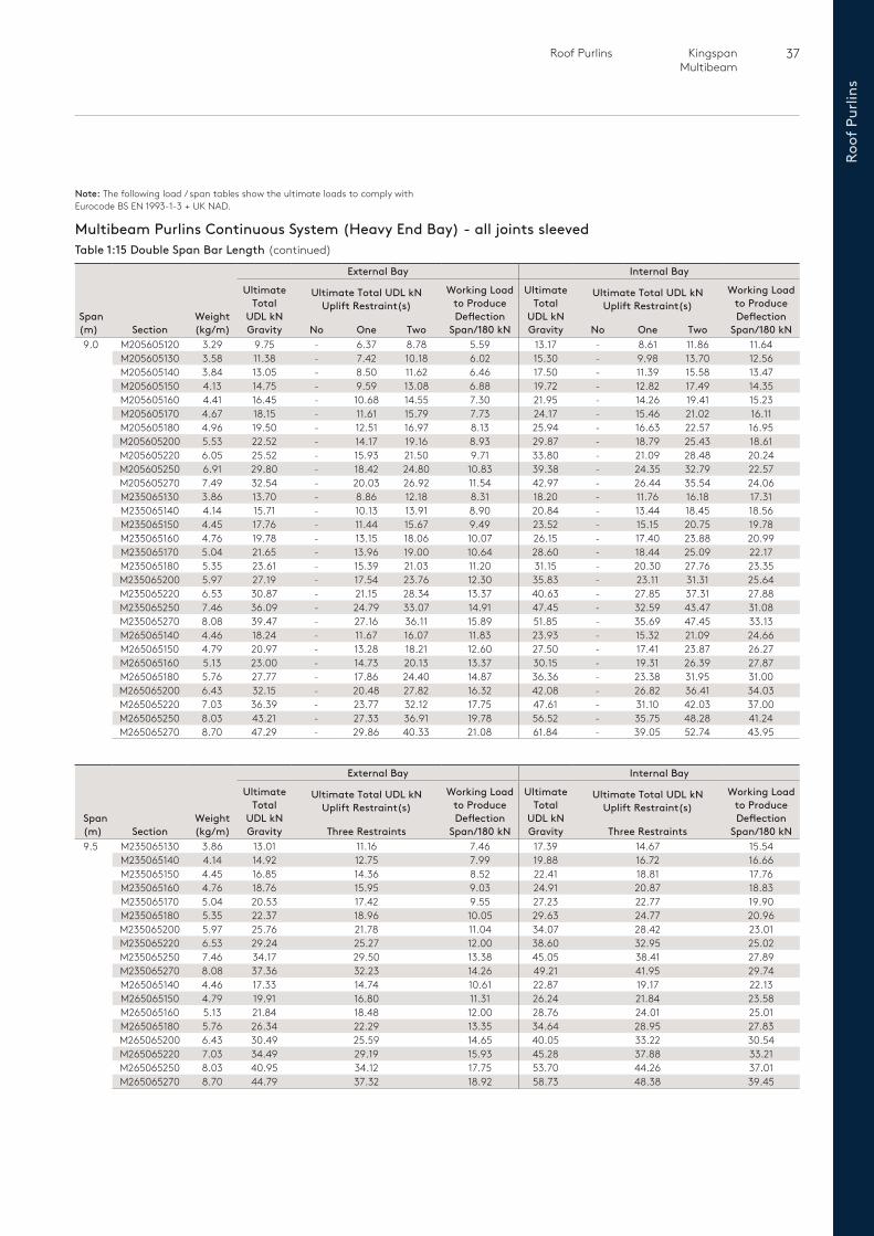
37 Roof Purlins Kingspan Multibeam
Roof
Pur
lins
Multibeam Purlins Continuous System (Heavy End Bay) - all joints sleevedTable 1:15 Double Span Bar Length (continued)
Span (m) Section
Weight (kg/m)
External Bay Internal Bay
Ultimate Total
UDL kNGravity
Ultimate Total UDL kN Uplift Restraint(s)
Working Load to Produce Deflection
Span/180 kN
Ultimate Total
UDL kNGravity
Ultimate Total UDL kN Uplift Restraint(s)
Working Load to Produce Deflection
Span/180 kNNo One Two No One Two9.0 M205605120 3.29 9.75 - 6.37 8.78 5.59 13.17 - 8.61 11.86 11.64
M205605130 3.58 11.38 - 7.42 10.18 6.02 15.30 - 9.98 13.70 12.56M205605140 3.84 13.05 - 8.50 11.62 6.46 17.50 - 11.39 15.58 13.47M205605150 4.13 14.75 - 9.59 13.08 6.88 19.72 - 12.82 17.49 14.35M205605160 4.41 16.45 - 10.68 14.55 7.30 21.95 - 14.26 19.41 15.23M205605170 4.67 18.15 - 11.61 15.79 7.73 24.17 - 15.46 21.02 16.11M205605180 4.96 19.50 - 12.51 16.97 8.13 25.94 - 16.63 22.57 16.95M205605200 5.53 22.52 - 14.17 19.16 8.93 29.87 - 18.79 25.43 18.61M205605220 6.05 25.52 - 15.93 21.50 9.71 33.80 - 21.09 28.48 20.24M205605250 6.91 29.80 - 18.42 24.80 10.83 39.38 - 24.35 32.79 22.57M205605270 7.49 32.54 - 20.03 26.92 11.54 42.97 - 26.44 35.54 24.06M235065130 3.86 13.70 - 8.86 12.18 8.31 18.20 - 11.76 16.18 17.31M235065140 4.14 15.71 - 10.13 13.91 8.90 20.84 - 13.44 18.45 18.56M235065150 4.45 17.76 - 11.44 15.67 9.49 23.52 - 15.15 20.75 19.78M235065160 4.76 19.78 - 13.15 18.06 10.07 26.15 - 17.40 23.88 20.99M235065170 5.04 21.65 - 13.96 19.00 10.64 28.60 - 18.44 25.09 22.17M235065180 5.35 23.61 - 15.39 21.03 11.20 31.15 - 20.30 27.76 23.35M235065200 5.97 27.19 - 17.54 23.76 12.30 35.83 - 23.11 31.31 25.64M235065220 6.53 30.87 - 21.15 28.34 13.37 40.63 - 27.85 37.31 27.88M235065250 7.46 36.09 - 24.79 33.07 14.91 47.45 - 32.59 43.47 31.08M235065270 8.08 39.47 - 27.16 36.11 15.89 51.85 - 35.69 47.45 33.13M265065140 4.46 18.24 - 11.67 16.07 11.83 23.93 - 15.32 21.09 24.66M265065150 4.79 20.97 - 13.28 18.21 12.60 27.50 - 17.41 23.87 26.27M265065160 5.13 23.00 - 14.73 20.13 13.37 30.15 - 19.31 26.39 27.87M265065180 5.76 27.77 - 17.86 24.40 14.87 36.36 - 23.38 31.95 31.00M265065200 6.43 32.15 - 20.48 27.82 16.32 42.08 - 26.82 36.41 34.03M265065220 7.03 36.39 - 23.77 32.12 17.75 47.61 - 31.10 42.03 37.00M265065250 8.03 43.21 - 27.33 36.91 19.78 56.52 - 35.75 48.28 41.24M265065270 8.70 47.29 - 29.86 40.33 21.08 61.84 - 39.05 52.74 43.95
Span (m) Section
Weight (kg/m)
External Bay Internal Bay
Ultimate Total
UDL kNGravity
Ultimate Total UDL kN Uplift Restraint(s)
Working Load to Produce Deflection
Span/180 kN
Ultimate Total
UDL kNGravity
Ultimate Total UDL kN Uplift Restraint(s)
Working Load to Produce Deflection
Span/180 kNThree Restraints Three Restraints9.5 M235065130 3.86 13.01 11.16 7.46 17.39 14.67 15.54
M235065140 4.14 14.92 12.75 7.99 19.88 16.72 16.66M235065150 4.45 16.85 14.36 8.52 22.41 18.81 17.76M235065160 4.76 18.76 15.95 9.03 24.91 20.87 18.83M235065170 5.04 20.53 17.42 9.55 27.23 22.77 19.90M235065180 5.35 22.37 18.96 10.05 29.63 24.77 20.96M235065200 5.97 25.76 21.78 11.04 34.07 28.42 23.01M235065220 6.53 29.24 25.27 12.00 38.60 32.95 25.02M235065250 7.46 34.17 29.50 13.38 45.05 38.41 27.89M235065270 8.08 37.36 32.23 14.26 49.21 41.95 29.74M265065140 4.46 17.33 14.74 10.61 22.87 19.17 22.13M265065150 4.79 19.91 16.80 11.31 26.24 21.84 23.58M265065160 5.13 21.84 18.48 12.00 28.76 24.01 25.01M265065180 5.76 26.34 22.29 13.35 34.64 28.95 27.83M265065200 6.43 30.49 25.59 14.65 40.05 33.22 30.54M265065220 7.03 34.49 29.19 15.93 45.28 37.88 33.21M265065250 8.03 40.95 34.12 17.75 53.70 44.26 37.01M265065270 8.70 44.79 37.32 18.92 58.73 48.38 39.45
Note: The following load / span tables show the ultimate loads to comply with Eurocode BS EN 1993-1-3 + UK NAD.
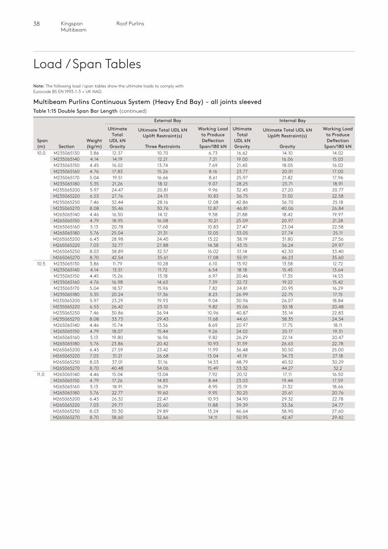
38 Roof PurlinsKingspan Multibeam
Load / Span Tables
Span (m) Section
Weight (kg/m)
External Bay Internal Bay
Ultimate Total
UDL kNGravity
Ultimate Total UDL kN Uplift Restraint(s)
Working Load to Produce Deflection
Span/180 kN
Ultimate Total
UDL kNGravity
Ultimate Total UDL kN Uplift Restraint(s)
Working Load to Produce Deflection
Span/180 kNThree Restraints Gravity10.0 M235065130 3.86 12.37 10.70 6.73 16.62 14.10 14.02
M235065140 4.14 14.19 12.21 7.21 19.00 16.06 15.03M235065150 4.45 16.02 13.74 7.69 21.40 18.05 16.02M235065160 4.76 17.83 15.26 8.16 23.77 20.01 17.00M235065170 5.04 19.51 16.66 8.61 25.97 21.82 17.96M235065180 5.35 21.26 18.12 9.07 28.25 23.71 18.91M235065200 5.97 24.47 20.81 9.96 32.45 27.20 20.77M235065220 6.53 27.76 24.13 10.83 36.75 31.50 22.58M235065250 7.46 32.44 28.16 12.08 42.86 36.70 25.18M235065270 8.08 35.46 30.76 12.87 46.81 40.06 26.84M265065140 4.46 16.50 14.12 9.58 21.88 18.42 19.97M265065150 4.79 18.95 16.08 10.21 25.09 20.97 21.28M265065160 5.13 20.78 17.68 10.83 27.47 23.04 22.58M265065180 5.76 25.04 21.31 12.05 33.05 27.74 25.11M265065200 6.43 28.98 24.45 13.22 38.19 31.80 27.56M265065220 7.03 32.77 27.88 14.38 43.15 36.24 29.97M265065250 8.03 38.89 32.57 16.02 51.14 42.30 33.40M265065270 8.70 42.54 35.61 17.08 55.91 46.23 35.60
10.5 M235065130 3.86 11.79 10.28 6.10 15.92 13.58 12.72M235065140 4.14 13.51 11.72 6.54 18.18 15.45 13.64M235065150 4.45 15.26 13.18 6.97 20.46 17.35 14.53M235065160 4.76 16.98 14.63 7.39 22.72 19.22 15.42M235065170 5.04 18.57 15.96 7.82 24.81 20.95 16.29M235065180 5.35 20.24 17.36 8.23 26.99 22.75 17.15M235065200 5.97 23.29 19.93 9.04 30.96 26.07 18.84M235065220 6.53 26.42 23.10 9.82 35.06 30.18 20.48M235065250 7.46 30.86 26.94 10.96 40.87 35.14 22.83M235065270 8.08 33.73 29.43 11.68 44.61 38.35 24.34M265065140 4.46 15.74 13.56 8.69 20.97 17.75 18.11M265065150 4.79 18.07 15.44 9.26 24.02 20.17 19.31M265065160 5.13 19.80 16.96 9.82 26.29 22.14 20.47M265065180 5.76 23.86 20.42 10.93 31.59 26.63 22.78M265065200 6.43 27.59 23.42 11.99 36.48 30.50 25.00M265065220 7.03 31.21 26.68 13.04 41.19 34.73 27.18M265065250 8.03 37.01 31.16 14.53 48.79 40.52 30.29M265065270 8.70 40.48 34.06 15.49 53.32 44.27 32.2
11.0 M265065140 4.46 15.04 13.04 7.92 20.12 17.11 16.50M265065150 4.79 17.26 14.83 8.44 23.03 19.44 17.59M265065160 5.13 18.91 16.29 8.95 25.19 21.32 18.66M265065180 5.76 22.77 19.60 9.95 30.25 25.61 20.76M265065200 6.43 26.32 22.47 10.93 34.90 29.32 22.78M265065220 7.03 29.77 25.60 11.88 39.39 33.36 24.77M265065250 8.03 35.30 29.89 13.24 46.64 38.90 27.60M265065270 8.70 38.60 32.66 14.11 50.95 42.47 29.42
Multibeam Purlins Continuous System (Heavy End Bay) - all joints sleevedTable 1:15 Double Span Bar Length (continued)
Note: The following load / span tables show the ultimate loads to comply with Eurocode BS EN 1993-1-3 + UK NAD.
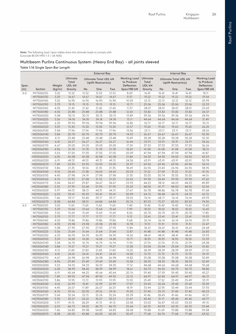
39 Roof Purlins Kingspan Multibeam
Roof
Pur
lins
Multibeam Purlins Continuous System (Heavy End Bay) - all joints sleevedTable 1:16 Single Span Bar Length
Span (m) Section
Weight (kg/m)
External Bay Internal Bay
Ultimate Total
UDL kNGravity
Ultimate Total UDL kN Uplift Restraint(s)
Working Load to Produce Deflection
Span/180 kN
Ultimate Total
UDL kNGravity
Ultimate Total UDL kN Uplift Restraint(s)
Working Load to Produce Deflection
Span/180 kNNo One Two No One Two6.0 M175065120 3.02 12.52 12.52 12.52 12.52 8.69 16.41 16.41 16.41 16.41 18.11
M175065130 3.29 14.67 14.67 14.67 14.67 9.37 19.22 19.22 19.22 19.22 19.54M175065140 3.52 16.90 16.90 16.90 16.90 10.05 22.12 22.12 22.12 22.12 20.95M175065150 3.79 19.15 19.15 19.15 19.15 10.71 25.06 25.06 25.06 25.06 22.33M175065160 4.05 21.42 21.42 21.42 21.42 11.37 28.01 28.01 28.01 28.01 23.69M175065180 4.55 25.88 25.88 25.88 25.88 12.65 33.82 33.82 33.82 33.82 26.37M175065200 5.08 30.13 30.13 30.13 30.13 13.89 39.36 39.36 39.36 39.36 28.96M175065220 5.56 34.18 34.18 34.18 34.18 15.11 44.64 44.64 44.64 44.64 31.49M175065250 6.35 39.96 39.96 39.96 39.96 16.85 52.17 52.17 52.17 52.17 35.13M205065120 3.29 15.30 15.30 15.30 15.30 12.57 19.65 19.65 19.65 19.65 26.20M205065130 3.58 17.96 17.96 17.96 17.96 13.56 23.11 23.11 23.11 23.11 28.26M205065140 3.84 20.70 20.70 20.70 20.70 14.53 26.67 26.67 26.67 26.67 30.30M205065150 4.13 23.48 23.48 23.48 23.48 15.49 30.28 30.28 30.28 30.28 32.30M205065160 4.41 26.27 26.27 26.27 26.27 16.44 33.91 33.91 33.91 33.91 34.26M205065170 4.67 29.05 29.05 29.05 29.05 17.39 37.53 37.53 37.53 37.53 36.26M205065180 4.96 31.78 31.78 31.78 31.78 18.29 41.08 41.08 41.08 41.08 38.13M205065200 5.53 37.05 37.05 37.05 37.05 20.09 47.94 47.94 47.94 47.94 41.87M205065220 6.05 42.08 42.08 42.08 42.08 21.84 54.50 54.50 54.50 54.50 45.53M205065250 6.91 49.31 49.31 49.31 49.31 24.36 63.91 63.91 63.91 63.91 50.78M205065270 7.49 53.95 53.95 53.95 53.95 25.97 69.96 69.96 69.96 69.96 54.14M235065130 3.86 21.35 18.56 21.35 21.35 18.69 26.96 23.43 26.96 26.96 38.95M235065140 4.14 24.65 21.38 24.65 24.65 20.03 31.22 27.09 31.22 31.22 41.76M235065150 4.45 27.98 24.19 27.98 27.98 21.35 35.55 30.74 35.55 35.55 44.51M235065160 4.76 31.33 27.08 31.33 31.33 22.65 39.90 34.49 39.90 39.90 47.22M235065170 5.04 34.67 29.87 34.67 34.67 23.93 44.23 38.12 44.23 44.23 49.89M235065180 5.35 37.95 32.68 37.95 37.95 25.20 48.50 41.77 48.50 48.50 52.54M235065200 5.97 44.31 38.13 44.31 44.31 27.67 56.78 48.86 56.78 56.78 57.68M235065220 6.53 50.41 45.55 50.41 50.41 30.09 64.72 58.48 64.72 64.72 62.72M235065250 7.46 59.17 53.40 59.17 59.17 33.55 76.14 68.71 76.14 76.14 69.93M235065270 8.08 64.84 58.51 64.84 64.84 35.76 83.53 75.37 83.53 83.53 74.55
6.5 M175065120 3.02 11.65 11.65 11.65 11.65 7.40 15.42 15.42 15.42 15.42 15.43M175065130 3.29 13.64 13.64 13.64 13.64 7.99 18.02 18.02 18.02 18.02 16.65M175065140 3.52 15.69 15.69 15.69 15.69 8.56 20.70 20.70 20.70 20.70 17.85M175065150 3.79 17.77 17.77 17.77 17.77 9.13 23.41 23.41 23.41 23.41 19.03M175065160 4.05 19.86 19.86 19.86 19.86 9.68 26.14 26.14 26.14 26.14 20.19M175065180 4.55 23.98 23.98 23.98 23.98 10.78 31.51 31.51 31.51 31.51 22.47M175065200 5.08 27.90 27.90 27.90 27.90 11.84 36.61 36.61 36.61 36.61 24.68M175065220 5.56 31.64 31.64 31.64 31.64 12.87 41.48 41.48 41.48 41.48 26.83M175065250 6.35 36.95 36.95 36.95 36.95 14.36 48.41 48.41 48.41 48.41 29.93M205065120 3.29 14.28 14.28 14.28 14.28 10.71 18.55 18.55 18.55 18.55 22.33M205065130 3.58 16.74 16.74 16.74 16.74 11.55 21.76 21.76 21.76 21.76 24.08M205065140 3.84 19.27 19.27 19.27 19.27 12.38 25.04 25.04 25.04 25.04 25.82M205065150 4.13 21.83 21.83 21.83 21.83 13.20 28.39 28.39 28.39 28.39 27.52M205065160 4.41 24.41 24.41 24.41 24.41 14.00 31.73 31.73 31.73 31.73 29.19M205065170 4.67 26.98 26.98 26.98 26.98 14.82 35.08 35.08 35.08 35.08 30.89M205065180 4.96 29.49 29.49 29.49 29.49 15.58 38.35 38.35 38.35 38.35 32.49M205065200 5.53 34.35 34.33 34.35 34.35 17.12 44.68 44.66 44.68 44.68 35.68M205065220 6.05 38.99 38.45 38.99 38.99 18.61 50.73 50.02 50.73 50.73 38.80M205065250 6.91 45.64 44.25 45.64 45.64 20.76 59.40 57.59 59.40 59.40 43.27M205065270 7.49 49.92 47.94 49.92 49.92 22.13 64.97 62.40 64.97 64.97 46.13M235065130 3.86 19.95 13.72 19.95 19.95 15.92 25.49 17.52 25.49 25.49 33.19M235065140 4.14 22.99 15.81 22.99 22.99 17.07 29.43 20.24 29.43 29.43 35.59M235065150 4.45 26.07 17.89 26.07 26.07 18.19 33.44 22.95 33.44 33.44 37.93M235065160 4.76 29.16 20.05 29.16 29.16 19.30 37.45 25.75 37.45 37.45 40.23M235065170 5.04 32.24 22.13 32.24 32.24 20.39 41.46 28.45 41.46 41.46 42.51M235065180 5.35 35.27 24.22 35.27 35.27 21.47 45.40 31.17 45.40 45.40 44.77M235065200 5.97 41.13 28.29 41.13 41.13 23.58 53.03 36.47 53.03 53.03 49.15M235065220 6.53 46.75 34.02 46.75 46.75 25.64 60.35 43.92 60.35 60.35 53.44M235065250 7.46 54.83 39.98 54.83 54.83 28.58 70.88 51.69 70.88 70.88 59.58M235065270 8.08 60.05 43.88 60.05 60.05 30.47 77.68 56.76 77.68 77.68 63.52
Note: The following load / span tables show the ultimate loads to comply with Eurocode BS EN 1993-1-3 + UK NAD.
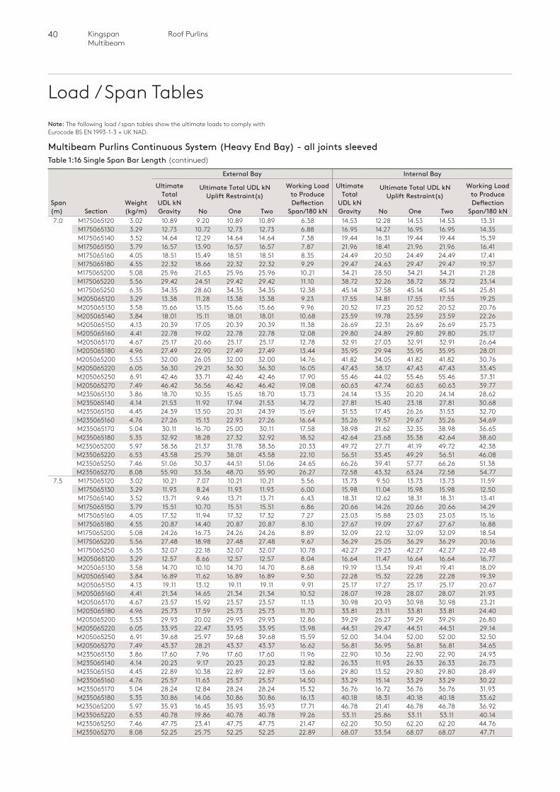
40 Roof PurlinsKingspan Multibeam
Load / Span Tables
Multibeam Purlins Continuous System (Heavy End Bay) - all joints sleevedTable 1:16 Single Span Bar Length (continued)
Span (m) Section
Weight (kg/m)
External Bay Internal Bay
Ultimate Total
UDL kNGravity
Ultimate Total UDL kN Uplift Restraint(s)
Working Load to Produce Deflection
Span/180 kN
Ultimate Total
UDL kNGravity
Ultimate Total UDL kN Uplift Restraint(s)
Working Load to Produce Deflection
Span/180 kNNo One Two No One Two7.0 M175065120 3.02 10.89 9.20 10.89 10.89 6.38 14.53 12.28 14.53 14.53 13.31
M175065130 3.29 12.73 10.72 12.73 12.73 6.88 16.95 14.27 16.95 16.95 14.35M175065140 3.52 14.64 12.29 14.64 14.64 7.38 19.44 16.31 19.44 19.44 15.39M175065150 3.79 16.57 13.90 16.57 16.57 7.87 21.96 18.41 21.96 21.96 16.41M175065160 4.05 18.51 15.49 18.51 18.51 8.35 24.49 20.50 24.49 24.49 17.41M175065180 4.55 22.32 18.66 22.32 22.32 9.29 29.47 24.63 29.47 29.47 19.37M175065200 5.08 25.96 21.63 25.96 25.96 10.21 34.21 28.50 34.21 34.21 21.28M175065220 5.56 29.42 24.51 29.42 29.42 11.10 38.72 32.26 38.72 38.72 23.14M175065250 6.35 34.35 28.60 34.35 34.35 12.38 45.14 37.58 45.14 45.14 25.81M205065120 3.29 13.38 11.28 13.38 13.38 9.23 17.55 14.81 17.55 17.55 19.25M205065130 3.58 15.66 13.15 15.66 15.66 9.96 20.52 17.23 20.52 20.52 20.76M205065140 3.84 18.01 15.11 18.01 18.01 10.68 23.59 19.78 23.59 23.59 22.26M205065150 4.13 20.39 17.05 20.39 20.39 11.38 26.69 22.31 26.69 26.69 23.73M205065160 4.41 22.78 19.02 22.78 22.78 12.08 29.80 24.89 29.80 29.80 25.17M205065170 4.67 25.17 20.66 25.17 25.17 12.78 32.91 27.03 32.91 32.91 26.64M205065180 4.96 27.49 22.90 27.49 27.49 13.44 35.95 29.94 35.95 35.95 28.01M205065200 5.53 32.00 26.05 32.00 32.00 14.76 41.82 34.05 41.82 41.82 30.76M205065220 6.05 36.30 29.21 36.30 36.30 16.05 47.43 38.17 47.43 47.43 33.45M205065250 6.91 42.46 33.71 42.46 42.46 17.90 55.46 44.02 55.46 55.46 37.31M205065270 7.49 46.42 36.56 46.42 46.42 19.08 60.63 47.74 60.63 60.63 39.77M235065130 3.86 18.70 10.35 15.65 18.70 13.73 24.14 13.35 20.20 24.14 28.62M235065140 4.14 21.53 11.92 17.94 21.53 14.72 27.81 15.40 23.18 27.81 30.68M235065150 4.45 24.39 13.50 20.31 24.39 15.69 31.53 17.45 26.26 31.53 32.70M235065160 4.76 27.26 15.13 22.93 27.26 16.64 35.26 19.57 29.67 35.26 34.69M235065170 5.04 30.11 16.70 25.00 30.11 17.58 38.98 21.62 32.35 38.98 36.65M235065180 5.35 32.92 18.28 27.32 32.92 18.52 42.64 23.68 35.38 42.64 38.60M235065200 5.97 38.36 21.37 31.78 38.36 20.33 49.72 27.71 41.19 49.72 42.38M235065220 6.53 43.58 25.79 38.01 43.58 22.10 56.51 33.45 49.29 56.51 46.08M235065250 7.46 51.06 30.37 44.51 51.06 24.65 66.26 39.41 57.77 66.26 51.38M235065270 8.08 55.90 33.36 48.70 55.90 26.27 72.58 43.32 63.24 72.58 54.77
7.5 M175065120 3.02 10.21 7.07 10.21 10.21 5.56 13.73 9.50 13.73 13.73 11.59M175065130 3.29 11.93 8.24 11.93 11.93 6.00 15.98 11.04 15.98 15.98 12.50M175065140 3.52 13.71 9.46 13.71 13.71 6.43 18.31 12.62 18.31 18.31 13.41M175065150 3.79 15.51 10.70 15.51 15.51 6.86 20.66 14.26 20.66 20.66 14.29M175065160 4.05 17.32 11.94 17.32 17.32 7.27 23.03 15.88 23.03 23.03 15.16M175065180 4.55 20.87 14.40 20.87 20.87 8.10 27.67 19.09 27.67 27.67 16.88M175065200 5.08 24.26 16.73 24.26 24.26 8.89 32.09 22.12 32.09 32.09 18.54M175065220 5.56 27.48 18.98 27.48 27.48 9.67 36.29 25.05 36.29 36.29 20.16M175065250 6.35 32.07 22.18 32.07 32.07 10.78 42.27 29.23 42.27 42.27 22.48M205065120 3.29 12.57 8.66 12.57 12.57 8.04 16.64 11.47 16.64 16.64 16.77M205065130 3.58 14.70 10.10 14.70 14.70 8.68 19.19 13.34 19.41 19.41 18.09M205065140 3.84 16.89 11.62 16.89 16.89 9.30 22.28 15.32 22.28 22.28 19.39M205065150 4.13 19.11 13.12 19.11 19.11 9.91 25.17 17.27 25.17 25.17 20.67M205065160 4.41 21.34 14.65 21.34 21.34 10.52 28.07 19.28 28.07 28.07 21.93M205065170 4.67 23.57 15.92 23.57 23.57 11.13 30.98 20.93 30.98 30.98 23.21M205065180 4.96 25.73 17.59 25.73 25.73 11.70 33.81 23.11 33.81 33.81 24.40M205065200 5.53 29.93 20.02 29.93 29.93 12.86 39.29 26.27 39.29 39.29 26.80M205065220 6.05 33.95 22.47 33.95 33.95 13.98 44.51 29.47 44.51 44.51 29.14M205065250 6.91 39.68 25.97 39.68 39.68 15.59 52.00 34.04 52.00 52.00 32.50M205065270 7.49 43.37 28.21 43.37 43.37 16.62 56.81 36.95 56.81 56.81 34.65M235065130 3.86 17.60 7.96 17.60 17.60 11.96 22.90 10.36 22.90 22.90 24.93M235065140 4.14 20.23 9.17 20.23 20.23 12.82 26.33 11.93 26.33 26.33 26.73M235065150 4.45 22.89 10.38 22.89 22.89 13.66 29.80 13.52 29.80 29.80 28.49M235065160 4.76 25.57 11.63 25.57 25.57 14.50 33.29 15.14 33.29 33.29 30.22M235065170 5.04 28.24 12.84 28.24 28.24 15.32 36.76 16.72 36.76 36.76 31.93M235065180 5.35 30.86 14.06 30.86 30.86 16.13 40.18 18.31 40.18 40.18 33.62M235065200 5.97 35.93 16.45 35.93 35.93 17.71 46.78 21.41 46.78 46.78 36.92M235065220 6.53 40.78 19.86 40.78 40.78 19.26 53.11 25.86 53.11 53.11 40.14M235065250 7.46 47.75 23.41 47.75 47.75 21.47 62.20 30.50 62.20 62.20 44.76M235065270 8.08 52.25 25.75 52.25 52.25 22.89 68.07 33.54 68.07 68.07 47.71
Note: The following load / span tables show the ultimate loads to comply with Eurocode BS EN 1993-1-3 + UK NAD.
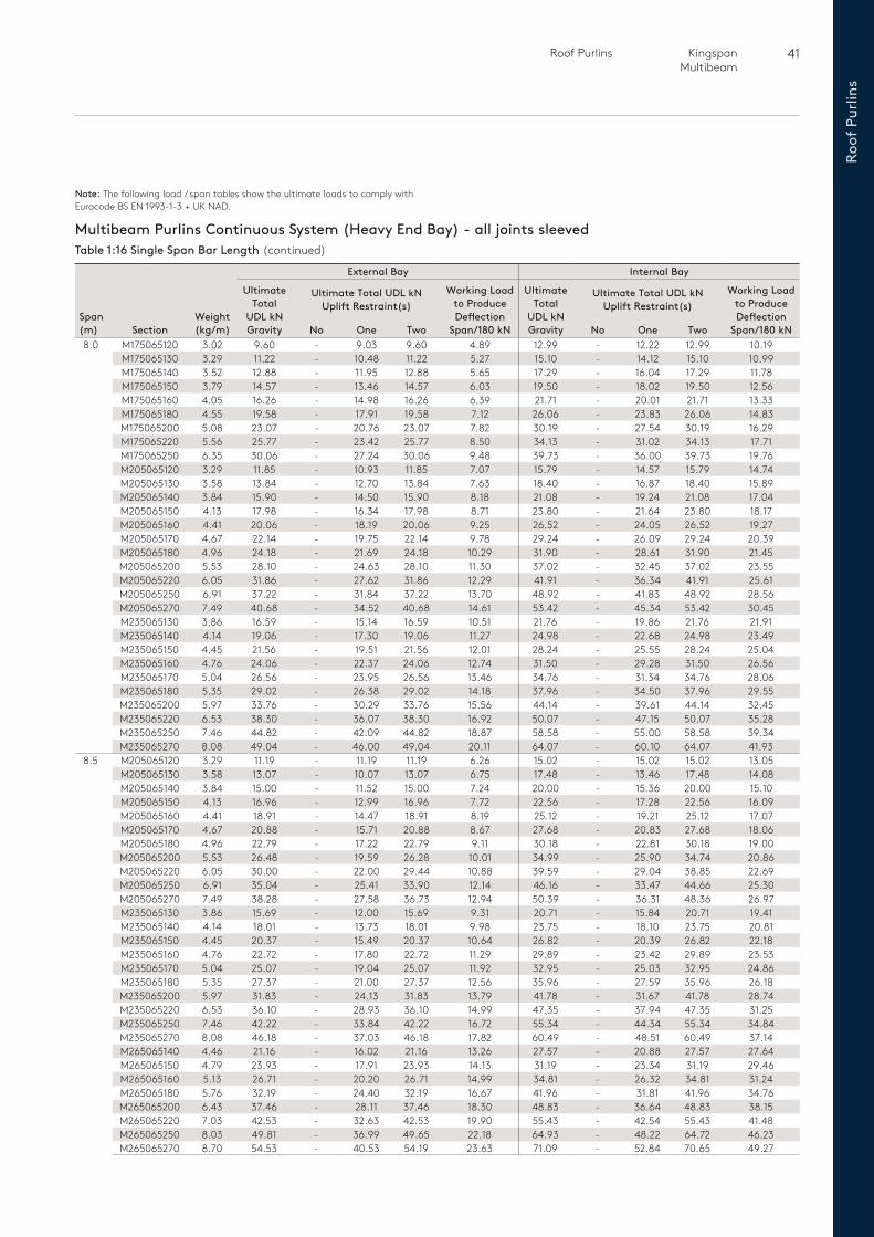
41 Roof Purlins Kingspan Multibeam
Roof
Pur
lins
Multibeam Purlins Continuous System (Heavy End Bay) - all joints sleevedTable 1:16 Single Span Bar Length (continued)
Span (m) Section
Weight (kg/m)
External Bay Internal Bay
Ultimate Total
UDL kNGravity
Ultimate Total UDL kN Uplift Restraint(s)
Working Load to Produce Deflection
Span/180 kN
Ultimate Total
UDL kNGravity
Ultimate Total UDL kN Uplift Restraint(s)
Working Load to Produce Deflection
Span/180 kNNo One Two No One Two8.0 M175065120 3.02 9.60 - 9.03 9.60 4.89 12.99 - 12.22 12.99 10.19
M175065130 3.29 11.22 - 10.48 11.22 5.27 15.10 - 14.12 15.10 10.99M175065140 3.52 12.88 - 11.95 12.88 5.65 17.29 - 16.04 17.29 11.78M175065150 3.79 14.57 - 13.46 14.57 6.03 19.50 - 18.02 19.50 12.56M175065160 4.05 16.26 - 14.98 16.26 6.39 21.71 - 20.01 21.71 13.33M175065180 4.55 19.58 - 17.91 19.58 7.12 26.06 - 23.83 26.06 14.83M175065200 5.08 23.07 - 20.76 23.07 7.82 30.19 - 27.54 30.19 16.29M175065220 5.56 25.77 - 23.42 25.77 8.50 34.13 - 31.02 34.13 17.71M175065250 6.35 30.06 - 27.24 30.06 9.48 39.73 - 36.00 39.73 19.76M205065120 3.29 11.85 - 10.93 11.85 7.07 15.79 - 14.57 15.79 14.74M205065130 3.58 13.84 - 12.70 13.84 7.63 18.40 - 16.87 18.40 15.89M205065140 3.84 15.90 - 14.50 15.90 8.18 21.08 - 19.24 21.08 17.04M205065150 4.13 17.98 - 16.34 17.98 8.71 23.80 - 21.64 23.80 18.17M205065160 4.41 20.06 - 18.19 20.06 9.25 26.52 - 24.05 26.52 19.27M205065170 4.67 22.14 - 19.75 22.14 9.78 29.24 - 26.09 29.24 20.39M205065180 4.96 24.18 - 21.69 24.18 10.29 31.90 - 28.61 31.90 21.45M205065200 5.53 28.10 - 24.63 28.10 11.30 37.02 - 32.45 37.02 23.55M205065220 6.05 31.86 - 27.62 31.86 12.29 41.91 - 36.34 41.91 25.61M205065250 6.91 37.22 - 31.84 37.22 13.70 48.92 - 41.83 48.92 28.56M205065270 7.49 40.68 - 34.52 40.68 14.61 53.42 - 45.34 53.42 30.45M235065130 3.86 16.59 - 15.14 16.59 10.51 21.76 - 19.86 21.76 21.91M235065140 4.14 19.06 - 17.30 19.06 11.27 24.98 - 22.68 24.98 23.49M235065150 4.45 21.56 - 19.51 21.56 12.01 28.24 - 25.55 28.24 25.04M235065160 4.76 24.06 - 22.37 24.06 12.74 31.50 - 29.28 31.50 26.56M235065170 5.04 26.56 - 23.95 26.56 13.46 34.76 - 31.34 34.76 28.06M235065180 5.35 29.02 - 26.38 29.02 14.18 37.96 - 34.50 37.96 29.55M235065200 5.97 33.76 - 30.29 33.76 15.56 44.14 - 39.61 44.14 32.45M235065220 6.53 38.30 - 36.07 38.30 16.92 50.07 - 47.15 50.07 35.28M235065250 7.46 44.82 - 42.09 44.82 18.87 58.58 - 55.00 58.58 39.34M235065270 8.08 49.04 - 46.00 49.04 20.11 64.07 - 60.10 64.07 41.93
8.5 M205065120 3.29 11.19 - 11.19 11.19 6.26 15.02 - 15.02 15.02 13.05M205065130 3.58 13.07 - 10.07 13.07 6.75 17.48 - 13.46 17.48 14.08M205065140 3.84 15.00 - 11.52 15.00 7.24 20.00 - 15.36 20.00 15.10M205065150 4.13 16.96 - 12.99 16.96 7.72 22.56 - 17.28 22.56 16.09M205065160 4.41 18.91 - 14.47 18.91 8.19 25.12 - 19.21 25.12 17.07M205065170 4.67 20.88 - 15.71 20.88 8.67 27.68 - 20.83 27.68 18.06M205065180 4.96 22.79 - 17.22 22.79 9.11 30.18 - 22.81 30.18 19.00M205065200 5.53 26.48 - 19.59 26.28 10.01 34.99 - 25.90 34.74 20.86M205065220 6.05 30.00 - 22.00 29.44 10.88 39.59 - 29.04 38.85 22.69M205065250 6.91 35.04 - 25.41 33.90 12.14 46.16 - 33.47 44.66 25.30M205065270 7.49 38.28 - 27.58 36.73 12.94 50.39 - 36.31 48.36 26.97M235065130 3.86 15.69 - 12.00 15.69 9.31 20.71 - 15.84 20.71 19.41M235065140 4.14 18.01 - 13.73 18.01 9.98 23.75 - 18.10 23.75 20.81M235065150 4.45 20.37 - 15.49 20.37 10.64 26.82 - 20.39 26.82 22.18M235065160 4.76 22.72 - 17.80 22.72 11.29 29.89 - 23.42 29.89 23.53M235065170 5.04 25.07 - 19.04 25.07 11.92 32.95 - 25.03 32.95 24.86M235065180 5.35 27.37 - 21.00 27.37 12.56 35.96 - 27.59 35.96 26.18M235065200 5.97 31.83 - 24.13 31.83 13.79 41.78 - 31.67 41.78 28.74M235065220 6.53 36.10 - 28.93 36.10 14.99 47.35 - 37.94 47.35 31.25M235065250 7.46 42.22 - 33.84 42.22 16.72 55.34 - 44.34 55.34 34.84M235065270 8.08 46.18 - 37.03 46.18 17.82 60.49 - 48.51 60.49 37.14M265065140 4.46 21.16 - 16.02 21.16 13.26 27.57 - 20.88 27.57 27.64M265065150 4.79 23.93 - 17.91 23.93 14.13 31.19 - 23.34 31.19 29.46M265065160 5.13 26.71 - 20.20 26.71 14.99 34.81 - 26.32 34.81 31.24M265065180 5.76 32.19 - 24.40 32.19 16.67 41.96 - 31.81 41.96 34.76M265065200 6.43 37.46 - 28.11 37.46 18.30 48.83 - 36.64 48.83 38.15M265065220 7.03 42.53 - 32.63 42.53 19.90 55.43 - 42.54 55.43 41.48M265065250 8.03 49.81 - 36.99 49.65 22.18 64.93 - 48.22 64.72 46.23M265065270 8.70 54.53 - 40.53 54.19 23.63 71.09 - 52.84 70.65 49.27
Note: The following load / span tables show the ultimate loads to comply with Eurocode BS EN 1993-1-3 + UK NAD.
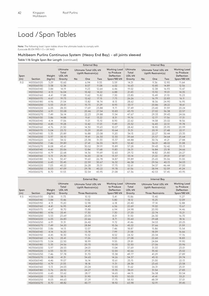
42 Roof PurlinsKingspan Multibeam
Load / Span Tables
Multibeam Purlins Continuous System (Heavy End Bay) - all joints sleevedTable 1:16 Single Span Bar Length (continued)
Span (m) Section
Weight (kg/m)
External Bay Internal Bay
Ultimate Total
UDL kNGravity
Ultimate Total UDL kN Uplift Restraint(s)
Working Load to Produce Deflection
Span/180 kN
Ultimate Total
UDL kNGravity
Ultimate Total UDL kN Uplift Restraint(s)
Working Load to Produce Deflection
Span/180 kNNo One Two No One Two9.0 M205065120 3.29 10.60 - 6.94 9.55 5.59 14.31 - 9.36 12.90 11.64
M205065130 3.58 12.38 - 8.07 11.08 6.02 16.63 - 10.85 14.89 12.56M205065140 3.84 14.19 - 9.23 12.64 6.46 19.02 - 12.38 16.93 13.47M205065150 4.13 16.04 - 10.42 14.22 6.88 21.43 - 13.92 19.01 14.35M205065160 4.41 17.88 - 11.62 15.82 7.30 23.85 - 15.49 21.10 15.23M205065170 4.67 19.73 - 12.62 17.15 7.73 26.26 - 16.79 22.83 16.11M205065180 4.96 21.54 - 13.82 18.74 8.13 28.62 - 18.36 24.90 16.95M205065200 5.53 25.01 - 15.73 21.29 8.93 33.17 - 20.86 28.22 18.61M205065220 6.05 28.33 - 17.69 23.88 9.71 37.49 - 23.40 31.59 20.24M205065250 6.91 33.08 - 20.46 27.54 10.83 43.70 - 27.02 36.38 22.57M205065270 7.49 36.14 - 22.23 29.88 11.54 47.67 - 29.33 39.43 24.06M235065130 3.86 14.88 - 9.61 13.22 8.31 19.76 - 12.77 17.56 17.31M235065140 4.14 17.06 - 11.01 15.10 8.90 22.62 - 14.58 20.02 18.56M235065150 4.45 19.28 - 12.42 17.01 9.49 25.52 - 16.43 22.51 19.78M235065160 4.76 21.50 - 14.30 19.63 10.07 28.42 - 18.90 25.95 20.99M235065170 5.04 23.72 - 15.29 20.81 10.64 31.31 - 20.19 27.48 22.17M235065180 5.35 25.89 - 16.88 23.08 11.20 34.15 - 22.27 30.44 23.35M235065200 5.97 30.10 - 19.41 26.30 12.30 39.64 - 25.57 34.64 25.64M235065220 6.53 34.12 - 23.38 31.33 13.37 44.88 - 30.76 41.21 27.88M235065250 7.46 39.89 - 27.41 36.55 14.91 52.42 - 36.01 48.02 31.08M235065270 8.08 43.61 - 30.02 39.91 15.89 57.28 - 39.43 52.42 33.13M265065140 4.46 20.06 - 12.84 17.68 11.83 26.31 - 16.84 23.18 24.66M265065150 4.79 22.68 - 14.36 19.69 12.60 29.72 - 18.82 25.80 26.27M265065160 5.13 25.30 - 16.20 22.14 13.37 33.14 - 21.22 29.01 27.87M265065180 5.76 30.47 - 19.60 26.78 14.87 39.89 - 25.65 35.06 31.00M265065200 6.43 35.45 - 22.59 30.67 16.32 46.38 - 29.56 40.13 34.03M265065220 7.03 40.22 - 26.28 35.51 17.75 52.61 - 34.37 46.44 37.00M265065250 8.03 47.09 - 29.78 40.22 19.78 61.56 - 38.94 52.59 41.24M265065270 8.70 51.53 - 32.54 43.95 21.08 67.36 - 42.53 57.45 43.95
Span (m) Section
Weight (kg/m)
External Bay Internal Bay
Ultimate Total
UDL kNGravity
Ultimate Total UDL kN Uplift Restraint(s)
Working Load to Produce Deflection
Span/180 kN
Ultimate Total
UDL kNGravity
Ultimate Total UDL kN Uplift Restraint(s)
Working Load to Produce Deflection
Span/180 kNThree Restraints Three Restraints9.5 M205065130 3.58 11.73 10.10 5.41 15.86 13.40 11.27
M205065140 3.84 13.46 11.52 5.80 18.12 15.25 12.09M205065150 4.13 15.20 12.98 6.18 20.40 17.14 12.88M205065160 4.41 16.95 14.43 6.56 22.69 19.02 13.67M205065170 4.67 18.70 15.88 6.94 24.98 20.90 14.46M205065180 4.96 20.41 17.30 7.30 27.20 22.74 15.21M205065200 5.53 23.69 20.05 8.01 31.50 26.30 16.70M205065220 6.05 26.83 22.66 8.71 35.60 29.68 18.16M205065250 6.91 31.31 26.42 9.72 41.46 34.53 20.25M205065270 7.49 34.20 28.84 10.36 45.22 37.66 21.59M235065130 3.86 14.13 12.07 7.46 18.87 15.86 15.54M235065140 4.14 16.20 13.78 7.99 21.58 18.09 16.66M235065150 4.45 18.30 15.52 8.52 24.32 20.34 17.76M235065160 4.76 20.41 17.26 9.03 27.08 22.60 18.83M235065170 5.04 22.50 18.99 9.55 29.81 24.84 19.90M235065180 5.35 24.56 20.70 10.05 32.50 27.06 20.96M235065200 5.97 28.53 24.01 11.04 37.69 31.33 23.01M235065220 6.53 32.33 27.15 12.00 42.66 35.42 25.02M235065250 7.46 37.78 31.70 13.38 49.77 41.29 27.89M235065270 8.08 41.31 34.65 14.26 54.37 45.10 29.74M265065140 4.46 19.07 16.14 10.61 25.15 21.00 22.13M265065150 4.79 21.55 18.18 11.31 28.38 23.65 23.58M265065160 5.13 24.03 20.24 12.00 31.62 26.31 25.01M265065180 5.76 28.92 24.27 13.35 38.01 31.54 27.83M265065200 6.43 33.62 28.17 14.65 44.15 36.58 30.54M265065220 7.03 38.13 31.90 15.93 50.03 41.41 33.21M265065250 8.03 44.63 37.29 17.75 58.50 48.39 37.01M265065270 8.70 48.82 40.77 18.92 63.98 52.91 39.45
Note: The following load / span tables show the ultimate loads to comply with Eurocode BS EN 1993-1-3 + UK NAD.
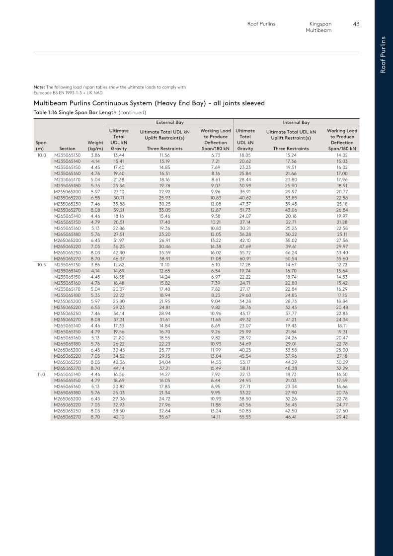
43 Roof Purlins Kingspan Multibeam
Roof
Pur
lins
Multibeam Purlins Continuous System (Heavy End Bay) - all joints sleevedTable 1:16 Single Span Bar Length (continued)
Span (m) Section
Weight (kg/m)
External Bay Internal Bay
Ultimate Total
UDL kNGravity
Ultimate Total UDL kN Uplift Restraint(s)
Working Load to Produce Deflection
Span/180 kN
Ultimate Total
UDL kNGravity
Ultimate Total UDL kN Uplift Restraint(s)
Working Load to Produce Deflection
Span/180 kNThree Restraints Three Restraints10.0 M235065130 3.86 13.44 11.56 6.73 18.05 15.24 14.02
M235065140 4.14 15.41 13.19 7.21 20.62 17.36 15.03M235065150 4.45 17.40 14.85 7.69 23.23 19.51 16.02M235065160 4.76 19.40 16.51 8.16 25.84 21.66 17.00M235065170 5.04 21.38 18.16 8.61 28.44 23.80 17.96M235065180 5.35 23.34 19.78 9.07 30.99 25.90 18.91M235065200 5.97 27.10 22.92 9.96 35.91 29.97 20.77M235065220 6.53 30.71 25.93 10.83 40.62 33.85 22.58M235065250 7.46 35.88 30.25 12.08 47.37 39.45 25.18M235065270 8.08 39.21 33.05 12.87 51.73 43.06 26.84M265065140 4.46 18.16 15.46 9.58 24.07 20.18 19.97M265065150 4.79 20.51 17.40 10.21 27.14 22.71 21.28M265065160 5.13 22.86 19.36 10.83 30.21 25.23 22.58M265065180 5.76 27.51 23.20 12.05 36.28 30.22 25.11M265065200 6.43 31.97 26.91 13.22 42.10 35.02 27.56M265065220 7.03 36.25 30.46 14.38 47.69 39.61 29.97M265065250 8.03 42.40 35.59 16.02 55.72 46.24 33.40M265065270 8.70 46.37 38.91 17.08 60.91 50.54 35.60
10.5 M235065130 3.86 12.82 11.10 6.10 17.28 14.67 12.72M235065140 4.14 14.69 12.65 6.54 19.74 16.70 13.64M235065150 4.45 16.58 14.24 6.97 22.22 18.74 14.53M235065160 4.76 18.48 15.82 7.39 24.71 20.80 15.42M235065170 5.04 20.37 17.40 7.82 27.17 22.84 16.29M235065180 5.35 22.22 18.94 8.23 29.60 24.85 17.15M235065200 5.97 25.80 21.95 9.04 34.28 28.73 18.84M235065220 6.53 29.23 24.81 9.82 38.76 32.43 20.48M235065250 7.46 34.14 28.94 10.96 45.17 37.77 22.83M235065270 8.08 37.31 31.61 11.68 49.32 41.21 24.34M265065140 4.46 17.33 14.84 8.69 23.07 19.43 18.11M265065150 4.79 19.56 16.70 9.26 25.99 21.84 19.31M265065160 5.13 21.80 18.55 9.82 28.92 24.26 20.47M265065180 5.76 26.22 22.23 10.93 34.69 29.01 22.78M265065200 6.43 30.45 25.77 11.99 40.23 33.58 25.00M265065220 7.03 34.52 29.15 13.04 45.54 37.96 27.18M265065250 8.03 40.36 34.04 14.53 53.17 44.29 30.29M265065270 8.70 44.14 37.21 15.49 58.11 48.38 32.29
11.0 M265065140 4.46 16.56 14.27 7.92 22.13 18.73 16.50M265065150 4.79 18.69 16.05 8.44 24.93 21.03 17.59M265065160 5.13 20.82 17.83 8.95 27.71 23.34 18.66M265065180 5.76 25.03 21.34 9.95 33.22 27.90 20.76M265065200 6.43 29.06 24.72 10.93 38.50 32.26 22.78M265065220 7.03 32.93 27.96 11.88 43.56 36.45 24.77M265065250 8.03 38.50 32.64 13.24 50.83 42.50 27.60M265065270 8.70 42.10 35.67 14.11 55.53 46.41 29.42
Note: The following load / span tables show the ultimate loads to comply with Eurocode BS EN 1993-1-3 + UK NAD.
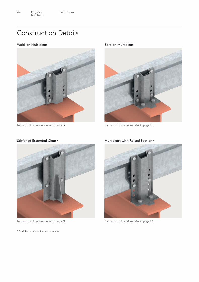
44 Roof PurlinsKingspan Multibeam
Construction Details
Stiffened Extended Cleat*
For product dimensions refer to page 21.
Weld-on Multicleat Bolt-on Multicleat
Multicleat with Raised Section*
For product dimensions refer to page 19. For product dimensions refer to page 20.
For product dimensions refer to page 20.
* Available in weld or bolt-on variations.
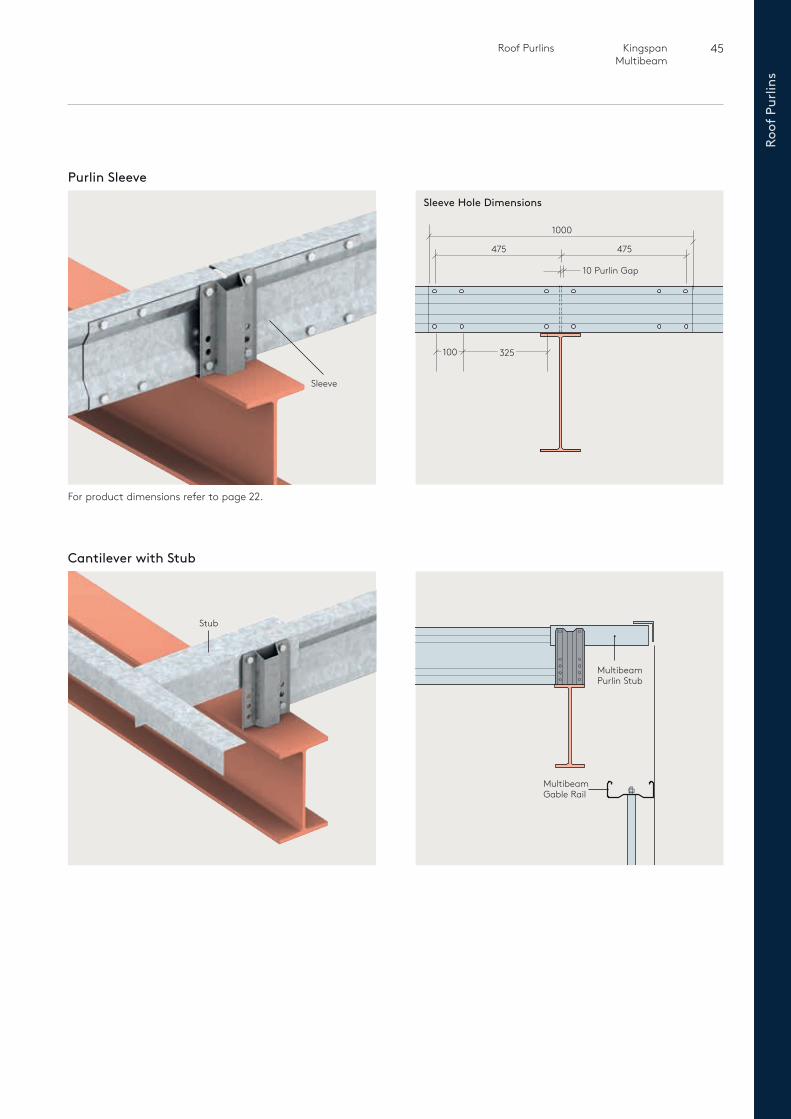
45 Roof Purlins Kingspan Multibeam
Roof
Pur
lins
For product dimensions refer to page 22.
Purlin Sleeve
Sleeve
Sleeve Hole Dimensions
1000
475 475
10 Purlin Gap
325
Cantilever with Stub
Stub
Multibeam Gable Rail
Multibeam Purlin Stub
100
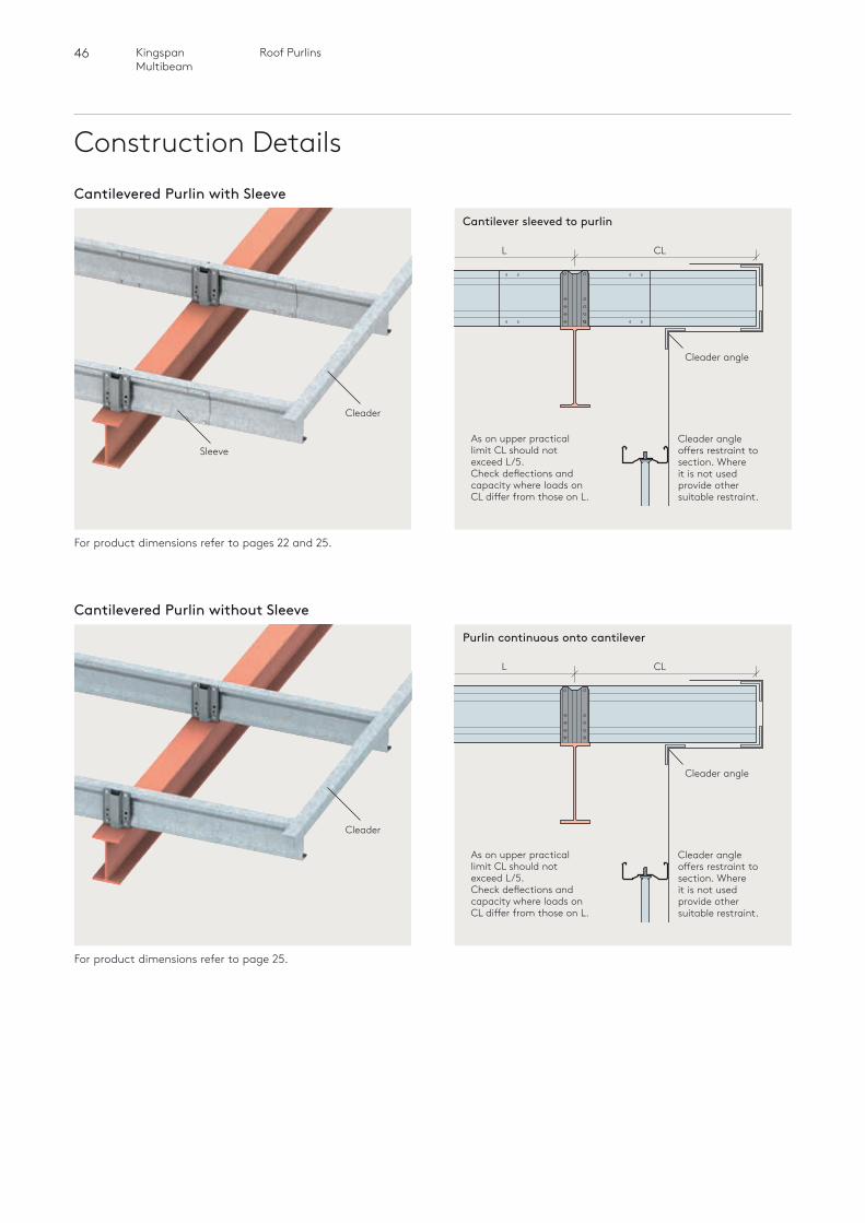
46 Roof PurlinsKingspan Multibeam
Construction Details
For product dimensions refer to pages 22 and 25.
Cantilevered Purlin with Sleeve
Cleader
SleeveAs on upper practical limit CL should not exceed L/5.Check deflections and capacity where loads on CL differ from those on L.
Cleader angle
Cleader angle offers restraint to section. Where it is not used provide other suitable restraint.
Cantilever sleeved to purlin
CLL
For product dimensions refer to page 25.
Cantilevered Purlin without Sleeve
Cleader
As on upper practical limit CL should not exceed L/5.Check deflections and capacity where loads on CL differ from those on L.
Cleader angle
Cleader angle offers restraint to section. Where it is not used provide other suitable restraint.
Purlin continuous onto cantilever
CLL
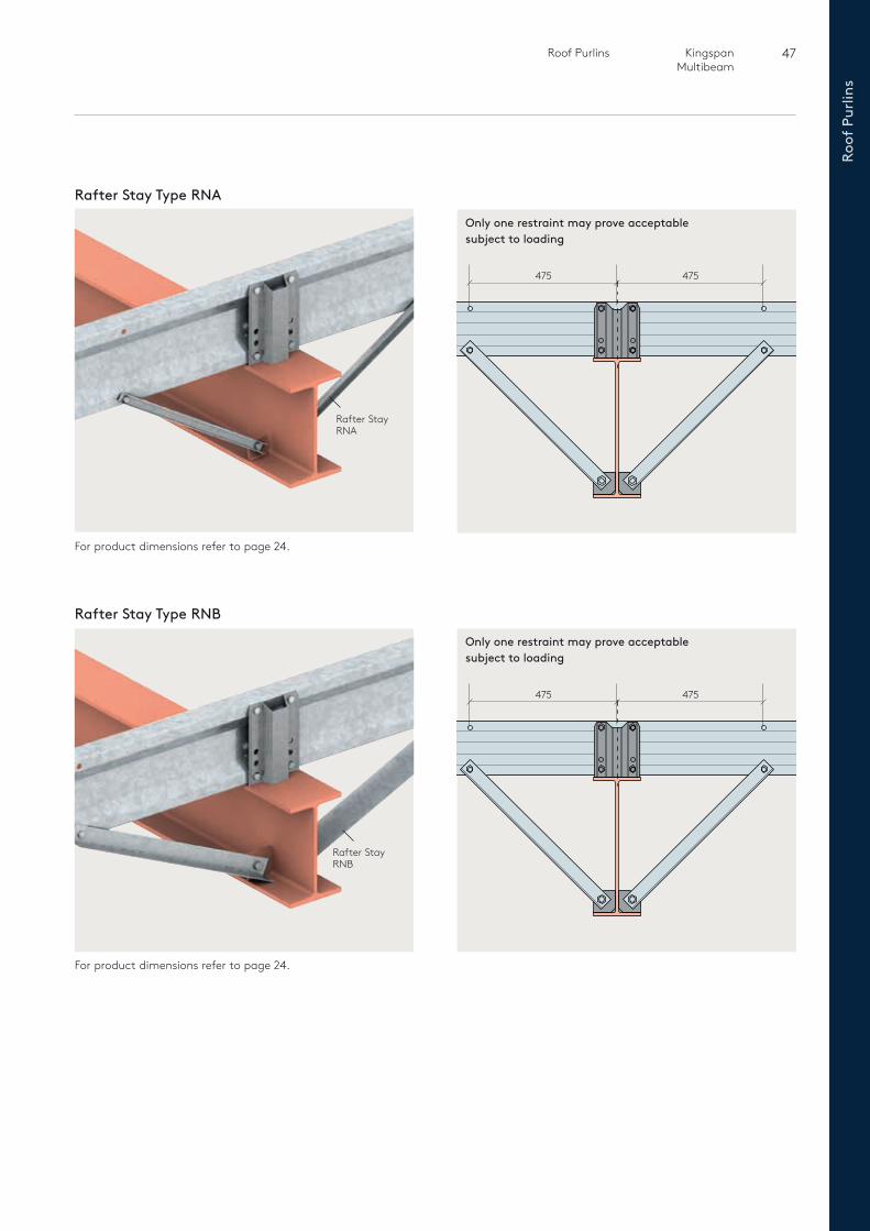
47 Roof Purlins Kingspan Multibeam
Roof
Pur
lins
For product dimensions refer to page 24.
For product dimensions refer to page 24.
Rafter Stay Type RNA
Rafter Stay Type RNB
Rafter Stay RNA
Rafter Stay RNB
Only one restraint may prove acceptable subject to loading
Only one restraint may prove acceptable subject to loading
475 475
475 475
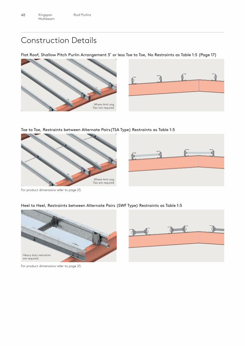
48 Roof PurlinsKingspan Multibeam
Construction Details
For product dimensions refer to page 23.
For product dimensions refer to page 23.
Flat Roof, Shallow Pitch Purlin Arrangement 3˚ or less Toe to Toe, No Restraints as Table 1:5 (Page 17)
Where Anti-sag Ties not required
Toe to Toe, Restraints between Alternate Pairs(TSA Type) Restraints as Table 1:5
Where Anti-sag Ties are required
Heel to Heel, Restraints between Alternate Pairs (SWF Type) Restraints as Table 1:5
Heavy duty restraints are required
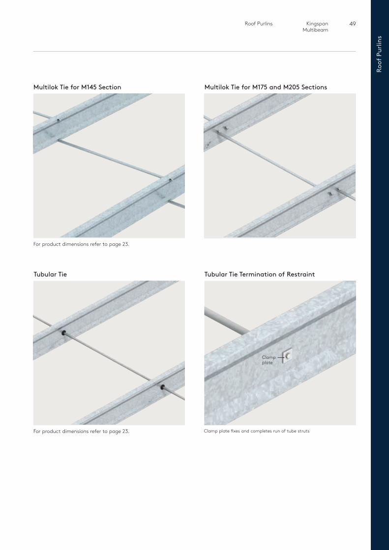
49 Roof Purlins Kingspan Multibeam
Roof
Pur
lins
Multilok Tie for M145 Section Multilok Tie for M175 and M205 Sections
Tubular Tie Tubular Tie Termination of Restraint
For product dimensions refer to page 23.
For product dimensions refer to page 23. Clamp plate fixes and completes run of tube struts
Clamp plate
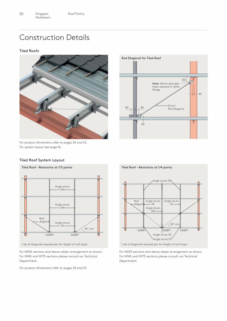
50 Roof PurlinsKingspan Multibeam
Construction Details
For product dimensions refer to pages 24 and 25. For system layout see page 16.
Tiled Roofs
40
80
130Note: 18mm diameter holes required in rafter flange
12mm Rod Diagonal 80
80
Tiled Roof System Layout
For M205 sections and above adopt arrangement as shown. For M145 and M175 sections please consult our Technical Department.
For M205 sections and above adopt arrangement as shown. For M145 and M175 sections please consult our Technical Department.
For product dimensions refer to pages 24 and 25.
1 set of diagonals required per 6m length of roof slope.
Rod diagonal
30˚ min
Angle struts SW
Angle struts SX
SWBP1 SWBP1
Angle struts SW
Tiled Roof – Restraints at 1/3 points
1 set of diagonals required per 6m length of roof slope.
Rod diagonal
30˚ min
Angle struts SX
Angle struts SX
Angle struts SW
Angle struts SX
Angle struts SY
Angle struts SW
Tiled Roof – Restraints at 1/4 points
Rod Diagonal for Tiled Roof
SWBP1 SWBP1 SWBP1
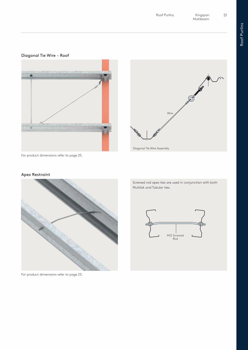
51 Roof Purlins Kingspan Multibeam
Roof
Pur
lins
For product dimensions refer to page 25.
Diagonal Tie Wire - Roof
For product dimensions refer to page 23.
Apex Restraint
Screwed rod apex ties are used in conjunction with both Multilok and Tubular ties.
M12 Screwed Rod
Diagonal Tie Wire Assembly
Wire

Eaves Beams
52 Eaves BeamsKingspan Multibeam
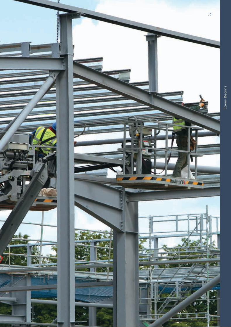
53
Eave
s Be
ams
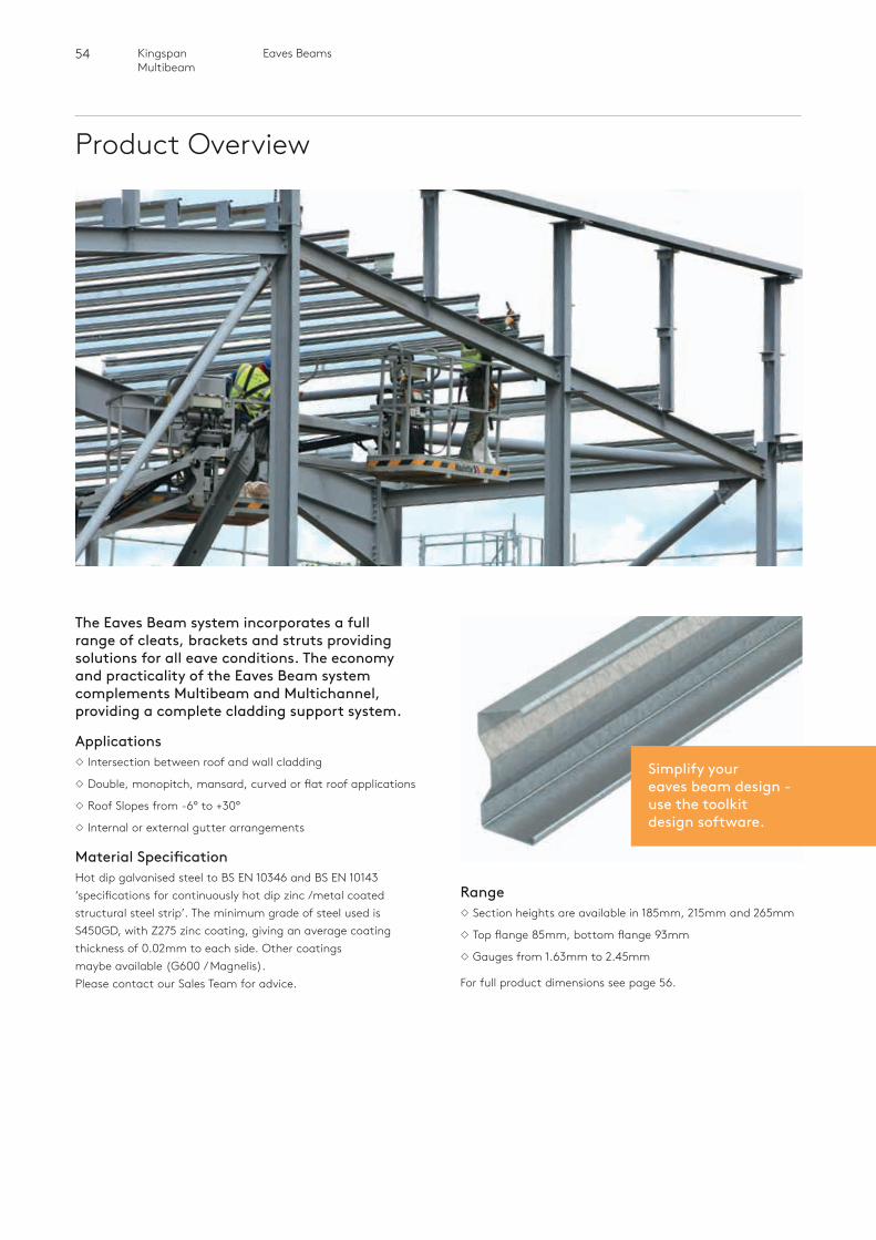
54 Eaves BeamsKingspan Multibeam
Product Overview
The Eaves Beam system incorporates a full range of cleats, brackets and struts providing solutions for all eave conditions. The economy and practicality of the Eaves Beam system complements Multibeam and Multichannel, providing a complete cladding support system.
ApplicationsIntersection between roof and wall cladding
Double, monopitch, mansard, curved or flat roof applications
Roof Slopes from -6° to +30°
Internal or external gutter arrangements
Material SpecificationHot dip galvanised steel to BS EN 10346 and BS EN 10143 ‘specifications for continuously hot dip zinc /metal coated structural steel strip’. The minimum grade of steel used is S450GD, with Z275 zinc coating, giving an average coating thickness of 0.02mm to each side. Other coatings maybe available (G600 / Magnelis). Please contact our Sales Team for advice.
RangeSection heights are available in 185mm, 215mm and 265mm
Top flange 85mm, bottom flange 93mm
Gauges from 1.63mm to 2.45mm
For full product dimensions see page 56.
Simplify your eaves beam design - use the toolkit design software.
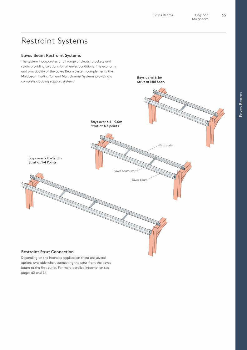
55 Eaves Beams Kingspan Multibeam
Eave
s Be
ams
Restraint SystemsEaves Beam Restraint SystemsThe system incorporates a full range of cleats, brackets and struts providing solutions for all eaves conditions. The economy and practicality of the Eaves Beam System complements the Multibeam Purlin, Rail and Multichannel Systems providing a complete cladding support system.
Restraint Strut ConnectionDepending on the intended application there are several options available when connecting the strut from the eaves beam to the first purlin. For more detailed information see pages 63 and 64.
First purlin
Eaves beam strut
Eaves beam
Bays over 9.0 – 12.0mStrut at 1/4 Points
Bays over 6.1 – 9.0mStrut at 1/3 points
Bays up to 6.1mStrut at Mid Span
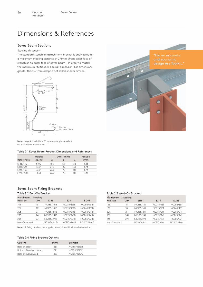
56 Eaves BeamsKingspan Multibeam
Dimensions & ReferencesEaves Beam Sections
Table 2:1 Eaves Beam Product Dimensions and References
Weight Dims (mm) Gauge References (kg/m) A B C (mm)E185/140 5.00 185 92 38 1.63E215/170 5.67 215 122 68 1.73E265/150 6.37 265 172 118 1.73E265/200 8.51 265 172 118 2.45
Stooling distance – The standard stanchion attachment bracket is engineered for a maximum stooling distance of 271mm (from outer face of stanchion to outer face of eaves beam). In order to match the maximum Multibeam side rail dimension. For dimensions greater than 271mm adopt a hot rolled stub or similar.
Note: angle A available in 3˚ increments, please select nearest to your requirement.
“For an accurateand economicdesign use Toolkit.”
13.0 @ <1.5mm gauge
6.7 @ <
1.5mm
gau
ge
93
3,8
Web Indent ( 1.0)
30 ( 0.5 )
90 ( 3 )
100 ( 2 )
90 (-6 /+30 ) R3.5( 0.5)
R5.0( 0.5)
R5.0( 0.5)
R5.0( 0.5 )
8.2 @ >
1.5mm
gau
ge
15.76 @ >
1.5mm
gau
ge
185 41.7
29
29
92,5
85
60
Dim
‘A’
6093
Gauge
20
Angle A = -6˚ to +30˚
All holes 18 Dia
35
38
36
Lip size Nominal 15mm
93D
im ‘C
’
85
Eaves Beam Fixing BracketsTable 2:2 Bolt-On BracketMultibeam Stooling Rail Size Dim E185 E215 E 265145 151 NC185/151B NC215/151B NC265/151B175 181 NC185/181B NC215/181B NC265/181B205 211 NC185/211B NC215/211B NC265/211B235 241 NC185/241B NC215/241B NC265/241B265 271 NC185/271B NC215/271B NC265/271BNon-Standard NC185/dimB NC215/dimB NC265/dimB
Note: all fixing brackets are supplied in unpainted black steel as standard.
Table 2:3 Weld-On BracketMultibeam Stooling Rail Size Dim E185 E215 E 265145 151 NC185/151 NC215/151 NC265/151175 181 NC185/181 NC215/181 NC265/181205 211 NC185/211 NC215/211 NC265/211235 241 NC185/241 NC215/241 NC265/241265 271 NC185/271 NC215/271 NC265/271Non-Standard NC185/dim NC215/dim NC265/dim
Table 2:4 Fixing Bracket Options
Options Suffix ExampleBolt-on cleat BB NC185/151BBBolt-on Powder coated BE NC185/151BEBolt-on Galvanised BG NC185/151BG
Dim
‘C’
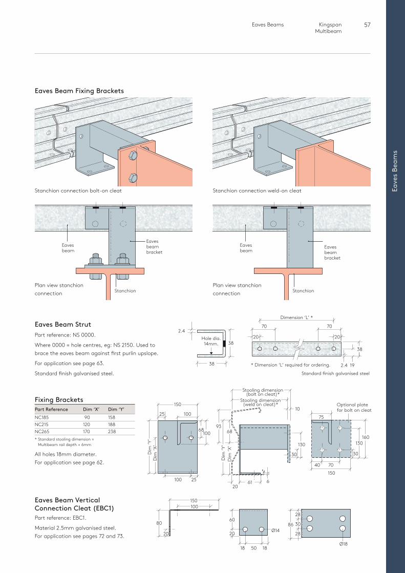
57 Eaves Beams Kingspan Multibeam
Eave
s Be
ams
Eaves Beam Fixing Brackets
Eavesbeambracket
Stanchion
Eavesbeam
Eavesbeambracket
Stanchion
Eavesbeam
Stanchion connection weld-on cleatStanchion connection bolt-on cleat
Plan view stanchion connection
Plan view stanchion connection
Eaves Beam Vertical Connection Cleat (EBC1)Part reference: EBC1.
Material 2.5mm galvanised steel.For application see pages 72 and 73.
150100
20
8060
Ø14
Ø18
20
18 18
28
28
3086
50
20
Fixing BracketsPart Reference Dim ‘X’ Dim ‘Y’NC185 90 158NC215 120 188NC265 170 238* Standard stooling dimension =
Multibeam rail depth + 6mm
All holes 18mm diameter.For application see page 62.
25 100
6
10
6893
30
160
Optional plate for bolt on cleat
10068
150
150
40 70
61
Dim
‘X’
Dim
‘Y’
25100
130130
Dim
‘Y’
Dim
‘X’
75
Stooling dimension (weld on cleat)*
Stooling dimension(bolt on cleat)*
30
Eaves Beam StrutPart reference: NS 0000.
Where 0000 = hole centres, eg: NS 2150. Used to brace the eaves beam against first purlin upslope.
For application see page 63.
Standard finish galvanised steel. Standard finish galvanised steel
* Dimension ‘L’ required for ordering.
38
38
2.470
Dimension ‘L’ *
70
20
192.4
38
Hole dia. 14mm.
20
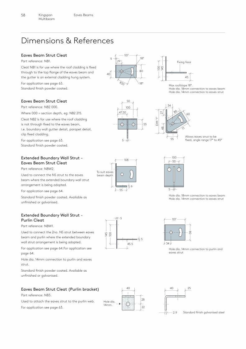
58 Eaves BeamsKingspan Multibeam
Dimensions & ReferencesEaves Beam Strut CleatPart reference: NB1.
Cleat NB1 is for use where the roof cladding is fixed through to the top flange of the eaves beam and the gutter is an external cladding hung system.
For application see page 63.Standard finish powder coated.
Extended Boundary Wall Strut - Eaves Beam Strut CleatPart reference: NBW2.
Used to connect the NS strut to the eaves beam where the extended boundary wall strut arrangement is being adopted.
For application see page 64.
Standard finish powder coated. Available as unfinished or galvanised.
Extended Boundary Wall Strut - Purlin CleatPart reference: NBW1.
Used to connect the 2no. NS strut between eaves beam and purlin where the extended boundary wall strut arrangement is being adopted.
For application see page 64.For application see page 64.
Hole dia. 14mm connection to purlin and eaves strut.
Standard finish powder coated. Available as unfinished or galvanised.
45
Fixing face
145
100
5
8040
29
R50
18°
18°
107
Max roofslope 18°. Hole dia. 18mm connection to eaves beam Hole dia. 14mm connection to eaves strut
Hole dia. 18mm connection to eaves beam Hole dia. 14mm connection to eaves strut
Eaves Beam Strut Cleat Part reference: NB2 000.
Where 000 = section depth, eg: NB2 215.
Cleat NB2 is for use where the roof cladding is not through fixed to the eaves beam, i.e. boundary wall gutter detail, parapet detail, clip fixed cladding.
For application see page 63.Standard finish powder coated.
47.50
100
R50
8660
55
55 DIM
‘Y’
4827
71
50
5
34
Allows eaves strut to be fixed, angle range 17° to 45°
Standard finish galvanised steel
40 25
2.9
40
28
22
Hole dia. 14mm.
Eaves Beam Strut Cleat (Purlin bracket)Part reference: NB3.
Used to attach the eaves strut to the purlin web.
For application see page 63.
108 50100
To suit eaves beam depth
655 5
Hole dia. 14mm connection to purlin and eaves strut
100
45.5
145
5
107
80
34
5
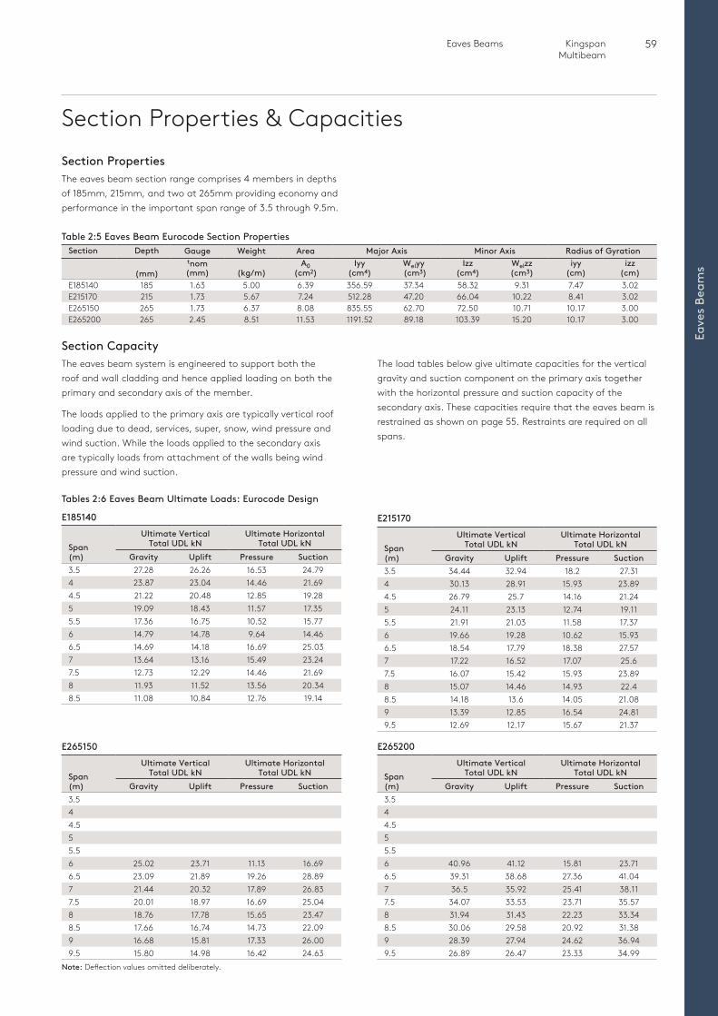
59 Eaves Beams Kingspan Multibeam
Eave
s Be
ams
Section Properties & Capacities
Tables 2:6 Eaves Beam Ultimate Loads: Eurocode Design
The eaves beam system is engineered to support both the roof and wall cladding and hence applied loading on both the primary and secondary axis of the member.
The loads applied to the primary axis are typically vertical roof loading due to dead, services, super, snow, wind pressure and wind suction. While the loads applied to the secondary axis are typically loads from attachment of the walls being wind pressure and wind suction.
The load tables below give ultimate capacities for the vertical gravity and suction component on the primary axis together with the horizontal pressure and suction capacity of the secondary axis. These capacities require that the eaves beam is restrained as shown on page 55. Restraints are required on all spans.
Section Capacity
The eaves beam section range comprises 4 members in depths of 185mm, 215mm, and two at 265mm providing economy and performance in the important span range of 3.5 through 9.5m.
Section Properties
Table 2:5 Eaves Beam Eurocode Section PropertiesSection Depth Gauge Weight Area Major Axis Minor Axis Radius of Gyration
(mm)
tnom (mm)
(kg/m)
A0 (cm2)
Iyy (cm4)
Welyy (cm3)
Izz (cm4)
Welzz (cm3)
iyy (cm)
izz (cm)
E185140 185 1.63 5.00 6.39 356.59 37.34 58.32 9.31 7.47 3.02E215170 215 1.73 5.67 7.24 512.28 47.20 66.04 10.22 8.41 3.02E265150 265 1.73 6.37 8.08 835.55 62.70 72.50 10.71 10.17 3.00E265200 265 2.45 8.51 11.53 1191.52 89.18 103.39 15.20 10.17 3.00
E185140
Span (m)
Ultimate Vertical Total UDL kN
Ultimate Horizontal Total UDL kN
Gravity Uplift Pressure Suction3.5 27.28 26.26 16.53 24.794 23.87 23.04 14.46 21.694.5 21.22 20.48 12.85 19.285 19.09 18.43 11.57 17.355.5 17.36 16.75 10.52 15.776 14.79 14.78 9.64 14.466.5 14.69 14.18 16.69 25.037 13.64 13.16 15.49 23.247.5 12.73 12.29 14.46 21.698 11.93 11.52 13.56 20.348.5 11.08 10.84 12.76 19.14
E265150
Span (m)
Ultimate Vertical Total UDL kN
Ultimate Horizontal Total UDL kN
Gravity Uplift Pressure Suction3.544.555.56 25.02 23.71 11.13 16.696.5 23.09 21.89 19.26 28.897 21.44 20.32 17.89 26.837.5 20.01 18.97 16.69 25.048 18.76 17.78 15.65 23.478.5 17.66 16.74 14.73 22.099 16.68 15.81 17.33 26.009.5 15.80 14.98 16.42 24.63
E265200
Span (m)
Ultimate Vertical Total UDL kN
Ultimate Horizontal Total UDL kN
Gravity Uplift Pressure Suction3.544.555.56 40.96 41.12 15.81 23.716.5 39.31 38.68 27.36 41.047 36.5 35.92 25.41 38.117.5 34.07 33.53 23.71 35.578 31.94 31.43 22.23 33.348.5 30.06 29.58 20.92 31.389 28.39 27.94 24.62 36.949.5 26.89 26.47 23.33 34.99
E215170
Span (m)
Ultimate Vertical Total UDL kN
Ultimate Horizontal Total UDL kN
Gravity Uplift Pressure Suction3.5 34.44 32.94 18.2 27.314 30.13 28.91 15.93 23.894.5 26.79 25.7 14.16 21.245 24.11 23.13 12.74 19.115.5 21.91 21.03 11.58 17.376 19.66 19.28 10.62 15.936.5 18.54 17.79 18.38 27.577 17.22 16.52 17.07 25.67.5 16.07 15.42 15.93 23.898 15.07 14.46 14.93 22.48.5 14.18 13.6 14.05 21.089 13.39 12.85 16.54 24.819.5 12.69 12.17 15.67 21.37
Note: Deflection values omitted deliberately.
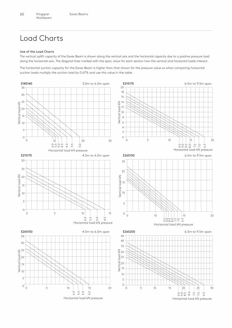
60 Eaves BeamsKingspan Multibeam
Load Charts
E215170 6.5m to 9.5m span
Horizontal load kN pressure
Vert
ical
load
kN
20
18
16
14
12
10
8
6
42
050 10 15 20
9.5
9.0
8.5
8.0
7.5
7.0
6.5
E265200 6.5m to 9.5m span
Horizontal load kN pressure
Vert
ical
load
kN
45
40
35
30
25
20
15
10
5
00 5 10 15 20 25 30
9.5
9.0
8.5
8.0
7.5
7.0
6.5
Use of the Load ChartsThe vertical uplift capacity of the Eaves Beam is shown along the vertical axis and the horizontal capacity due to a positive pressure load along the horizontal axis. The diagonal lines marked with the span, show for each section how the vertical and horizontal loads interact.
The horizontal suction capacity for the Eaves Beam is higher than that shown for the pressure value so when comparing horizontal suction loads multiply the suction load by 0.67% and use this value in the table.
E265150 4.5m to 6.0m span
Horizontal load kN pressure
Vert
ical
load
kN
35
30
25
20
15
10
5
00 5 10 15 20
6.0
5.5
5.0
4.5
E215170 4.5m to 6.0m span
Horizontal load kN pressure
Vert
ical
load
kN
30
25
20
15
10
5
00 5 10 15
6.0
5.5
5.0
4.5
E185140 3.0m to 6.0m span
Horizontal load kN pressure
Vert
ical
load
kN
35
30
25
20
15
10
5
00 10
6.0
5.5
5.0
4.5
4.0
3.5
3.0
20 30
Horizontal load kN pressure
E265150 6.5m to 9.5m span
25
20
15
10
5
00 10 15 20
9.5
9.0
8.5
8.0
7.5
7.0
6.5
Vert
ical
load
kN

61 Eaves Beams Kingspan Multibeam
Eave
s Be
ams
Loadings
Table 2:7
Load Type Eurocode Load Factor
Dead load 1.35 Dead load restraining uplift or overturning 1.0 Service load 1.35 Imposed load 1.5 Wind load 1.5 Imposed Snow 1.5 Accidental snow (drift) 1.0
Bar lengths up to 12m in length are possible subject to minimum volumes, contact sales or customer service for further details.
Bar Length
Load Factors
Eaves Beam DesignWith loading about both axis’s and the number of load combinations to consider the manual design process for the eaves beam can be tedious and time consuming - For an easy and comprehensive analysis applying all the relevant applied load combinations and factors it is recommended that the designer uses the Kingspan Toolkit software available from the Kingspan Structural products web site. www.kingspanpanels.co.uk/structural
Deflection LimitsIndustry accepted vertical deflection limits for typical light weight cladding are normally set to span / 180 (as for a general purlin).
Where the applied dead load is a higher proportion of the total load than for normal roof weights (example would be using a concrete or clay tile roof) then consider using a higher deflection limit. This gives a more acceptable eaves sightline.
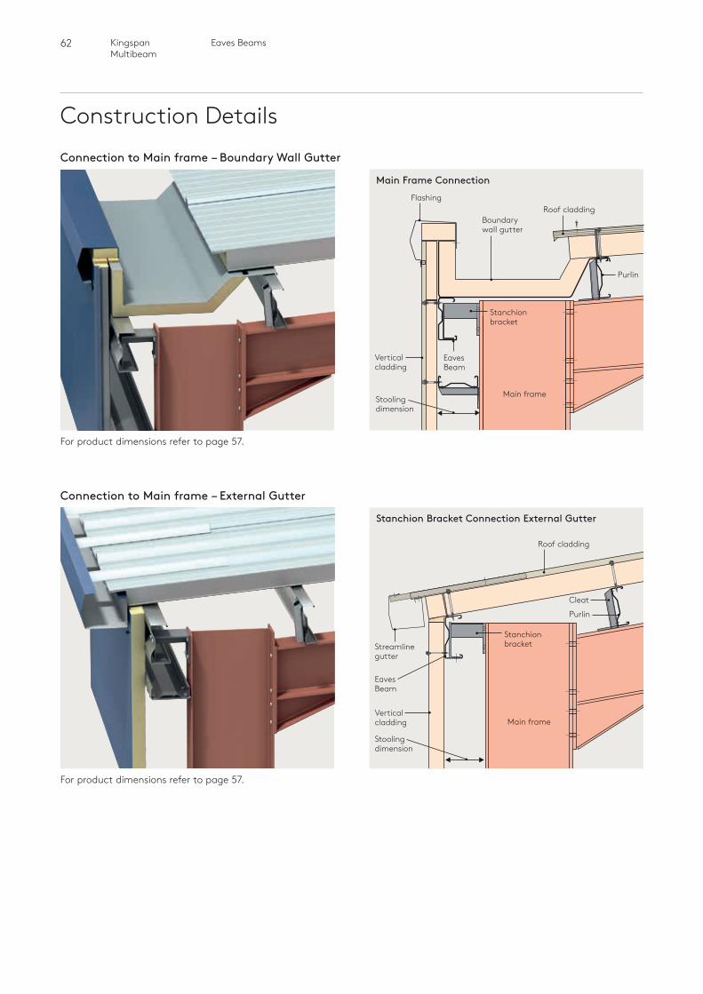
62 Eaves BeamsKingspan Multibeam
Construction DetailsConnection to Main frame – Boundary Wall Gutter
For product dimensions refer to page 57.
Boundary wall gutter
FlashingRoof cladding
Eaves Beam
Verticalcladding
Stanchionbracket
Main frame
Purlin
Stoolingdimension
Main Frame Connection
Connection to Main frame – External Gutter
For product dimensions refer to page 57.
Main frame
Roof cladding
Eaves Beam
Verticalcladding
Stoolingdimension
Streamlinegutter
Stanchionbracket
Cleat
Purlin
Stanchion Bracket Connection External Gutter
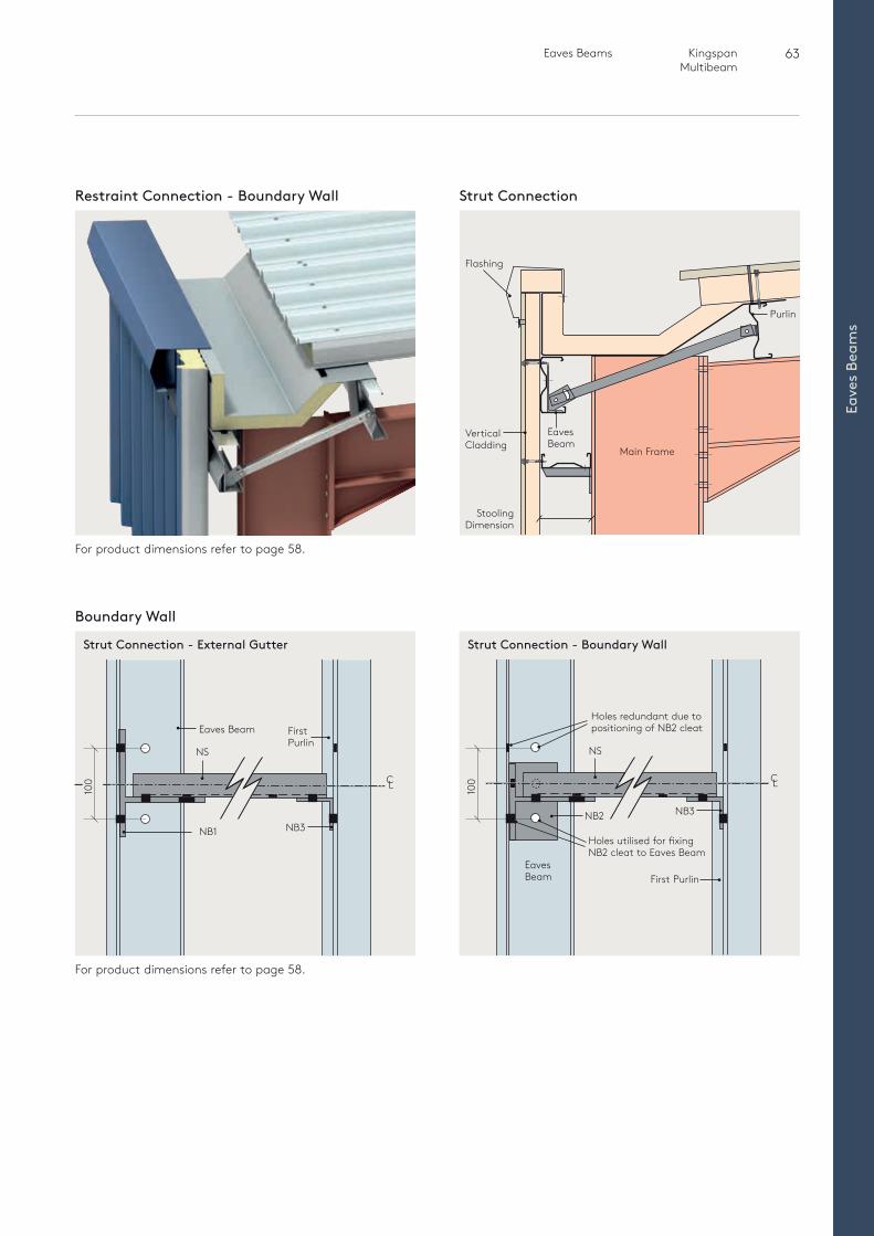
63 Eaves Beams Kingspan Multibeam
Eave
s Be
ams
For product dimensions refer to page 58.
For product dimensions refer to page 58.
Boundary Wall
100
NB2
Holes utilised for fixing NB2 cleat to Eaves Beam
First PurlinEavesBeam
NS
CL
NB3
Holes redundant due to positioning of NB2 cleat
Strut Connection - Boundary WallStrut Connection - External Gutter
Restraint Connection - Boundary Wall Strut Connection
Eaves Beam
NB1
FirstPurlin
NS
CL
NB3
100
Vertical Cladding Main Frame
Flashing
Purlin
Eaves Beam
StoolingDimension
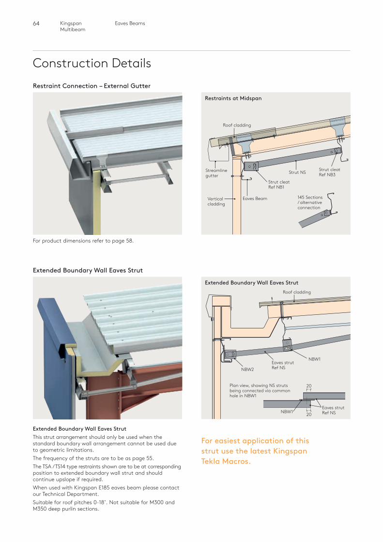
64 Eaves BeamsKingspan Multibeam
NBW2Eaves strutRef NS
NBW1
Roof cladding
Construction Details
For product dimensions refer to page 58.
Restraint Connection – External Gutter
Restraints at Midspan
Strut cleatRef NB1
Strut NS
Eaves BeamVerticalcladding
Roof cladding
Streamlinegutter
145 Sections / alternative connection
Strut cleatRef NB3
Extended Boundary Wall Eaves Strut
Extended Boundary Wall Eaves StrutThis strut arrangement should only be used when the standard boundary wall arrangement cannot be used due to geometric limitations.The frequency of the struts are to be as page 55.The TSA / TS14 type restraints shown are to be at corresponding position to extended boundary wall strut and should continue upslope if required.When used with Kingspan E185 eaves beam please contact our Technical Department.Suitable for roof pitches 0-18˚. Not suitable for M300 and M350 deep purlin sections.
Extended Boundary Wall Eaves Strut
For easiest application of this strut use the latest Kingspan Tekla Macros.
Plan view, showing NS struts being connected via common hole in NBW1
NBW1 20
20
Eaves strutRef NS
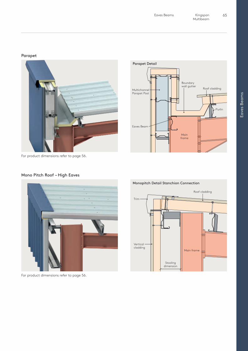
65 Eaves Beams Kingspan Multibeam
Eave
s Be
ams
Boundary wall gutter
Multichannel Parapet Post
Roof cladding
Eaves Beam
Mainframe
Purlin
Parapet
For product dimensions refer to page 56.
Mono Pitch Roof – High Eaves
For product dimensions refer to page 56.
Parapet Detail
Roof cladding
Trim
Verticalcladding
Main frame
Stoolingdimension
Monopitch Detail Stanchion Connection

66 Cladding RailsKingspan Multibeam
Cladding Rails
67
Cla
ddin
g Ra
ils
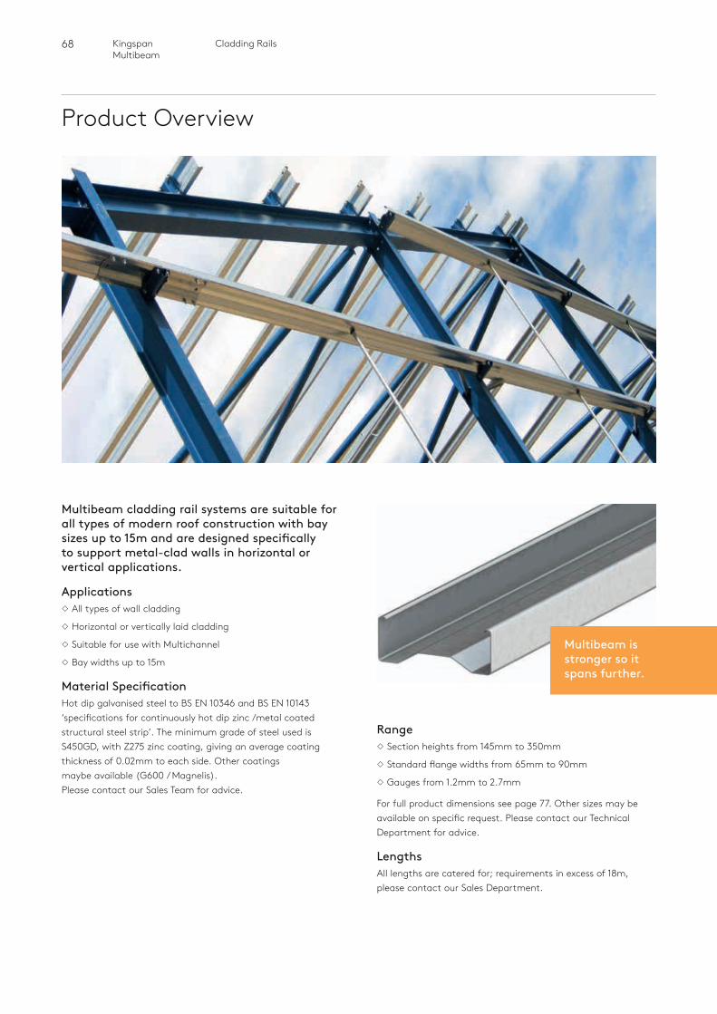
68 Cladding RailsKingspan Multibeam
Product Overview
Multibeam cladding rail systems are suitable for all types of modern roof construction with bay sizes up to 15m and are designed specifically to support metal-clad walls in horizontal or vertical applications.
ApplicationsAll types of wall cladding
Horizontal or vertically laid cladding
Suitable for use with Multichannel
Bay widths up to 15m
Material SpecificationHot dip galvanised steel to BS EN 10346 and BS EN 10143 ‘specifications for continuously hot dip zinc /metal coated structural steel strip’. The minimum grade of steel used is S450GD, with Z275 zinc coating, giving an average coating thickness of 0.02mm to each side. Other coatings maybe available (G600 / Magnelis). Please contact our Sales Team for advice.
RangeSection heights from 145mm to 350mm
Standard flange widths from 65mm to 90mm
Gauges from 1.2mm to 2.7mm
For full product dimensions see page 77. Other sizes may be available on specific request. Please contact our Technical Department for advice.
LengthsAll lengths are catered for; requirements in excess of 18m, please contact our Sales Department.
Multibeam is stronger so it spans further.
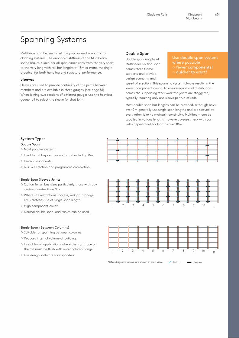
69 Cladding Rails Kingspan Multibeam
Cla
ddin
g Ra
ils
Use double span system where possible fewer components! quicker to erect!
Spanning Systems
1
1
2
2
3
3
4
4
5
5
6
6
7
7
8
8
9
9
10
10
11
11
System TypesDouble SpanMost popular system.
Ideal for all bay centres up to and including 8m.
Fewer components.
Quicker erection and programme completion.
Multibeam can be used in all the popular and economic rail cladding systems. The enhanced stiffness of the Multibeam shape makes it ideal for all span dimensions from the very short to the very long with rail bar lengths of 18m or more, making it practical for both handling and structural performance.
SleevesSleeves are used to provide continuity at the joints between members and are available in three gauges (see page 81). When joining two sections of different gauges use the heaviest gauge rail to select the sleeve for that joint.
Double SpanDouble span lengths of Multibeam section span across three frame supports and provide design economy and speed of erection. This spanning system always results in the lowest component count. To ensure equal load distribution across the supporting steel work the joints are staggered, typically requiring only one sleeve per run of rails.
Most double span bar lengths can be provided, although bays over 9m generally use single span lengths and are sleeved at every other joint to maintain continuity. Multibeam can be supplied in various lengths, however, please check with our Sales department for lengths over 18m.
Single Span Sleeved JointsOption for all bay sizes particularly those with bay
centres greater than 8m.
Where site restrictions (access, weight, cranage etc.) dictates use of single span length.
High component count.
Normal double span load tables can be used.
Single Span (Between Columns)Suitable for spanning between columns.
Reduces internal volume of building.
Useful for all applications where the front face of the rail must be flush with outer column flange.
Use design software for capacities.
Joint SleeveNote: diagrams above are shown in plan view.
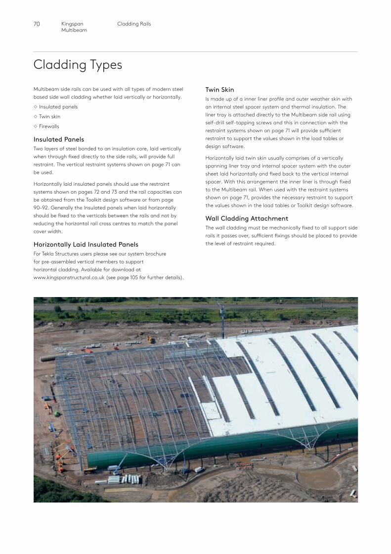
70 Cladding RailsKingspan Multibeam
Cladding Types
Multibeam side rails can be used with all types of modern steel based side wall cladding whether laid vertically or horizontally.
Insulated panels
Twin skin
Firewalls
Insulated PanelsTwo layers of steel bonded to an insulation core, laid vertically when through fixed directly to the side rails, will provide full restraint. The vertical restraint systems shown on page 71 can be used.
Horizontally laid insulated panels should use the restraint systems shown on pages 72 and 73 and the rail capacities can be obtained from the Toolkit design software or from page 90–92. Generally the Insulated panels when laid horizontally should be fixed to the verticals between the rails and not by reducing the horizontal rail cross centres to match the panel cover width.
Horizontally Laid Insulated PanelsFor Tekla Structures users please see our system brochure for pre-assembled vertical members to support horizontal cladding. Available for download at www.kingspanstructural.co.uk (see page 105 for further details).
Twin Skin Is made up of a inner liner profile and outer weather skin with an internal steel spacer system and thermal insulation. The liner tray is attached directly to the Multibeam side rail using self-drill self-tapping screws and this in connection with the restraint systems shown on page 71 will provide sufficient restraint to support the values shown in the load tables or design software.
Horizontally laid twin skin usually comprises of a vertically spanning liner tray and internal spacer system with the outer sheet laid horizontally and fixed back to the vertical internal spacer. With this arrangement the inner liner is through fixed to the Multibeam rail. When used with the restraint systems shown on page 71, provides the necessary restraint to support the values shown in the load tables or Toolkit design software.
Wall Cladding AttachmentThe wall cladding must be mechanically fixed to all support side rails it passes over, sufficient fixings should be placed to provide the level of restraint required.
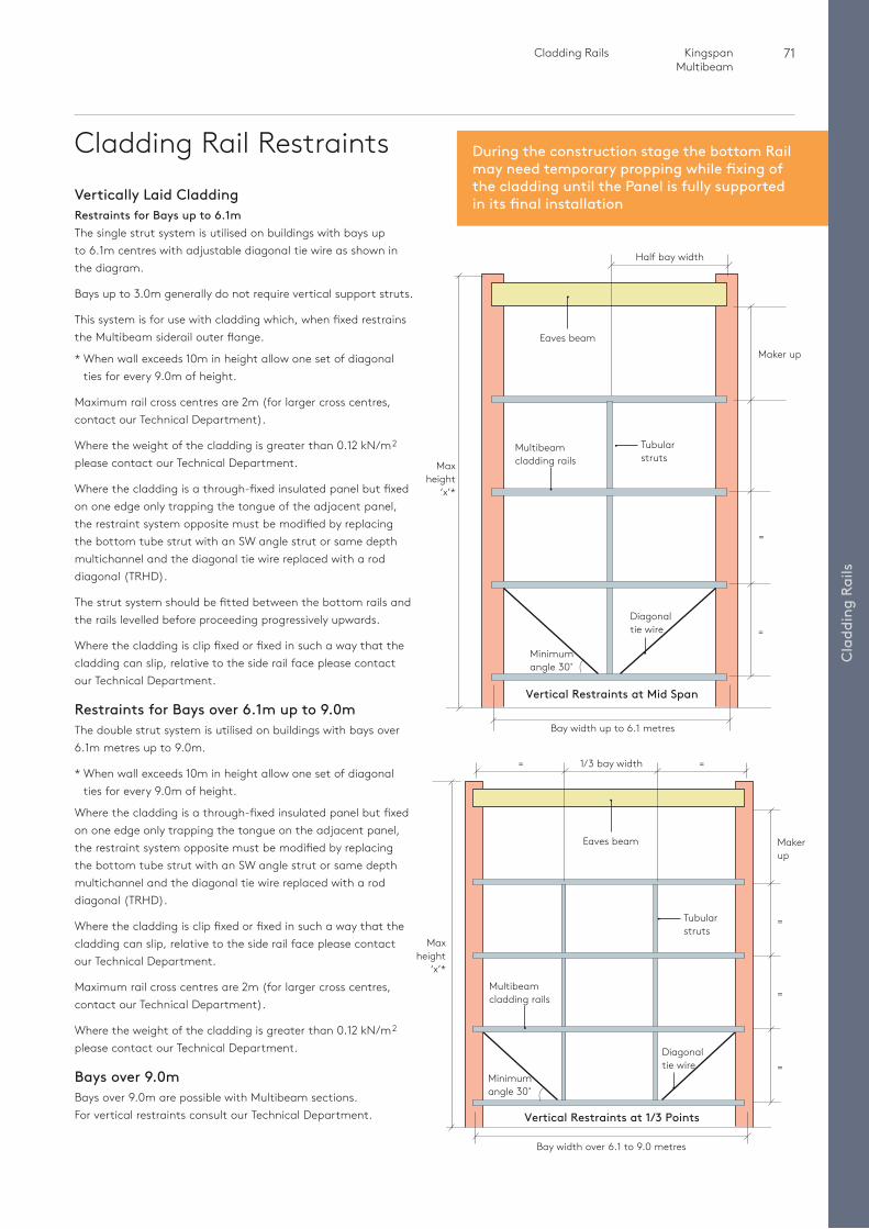
71 Cladding Rails Kingspan Multibeam
Cla
ddin
g Ra
ils
During the construction stage the bottom Rail may need temporary propping while fixing of the cladding until the Panel is fully supported in its final installation
Cladding Rail Restraints
=1/3 bay width=
Vertically Laid CladdingRestraints for Bays up to 6.1mThe single strut system is utilised on buildings with bays up to 6.1m centres with adjustable diagonal tie wire as shown in the diagram.
Bays up to 3.0m generally do not require vertical support struts.
This system is for use with cladding which, when fixed restrains the Multibeam siderail outer flange.
* When wall exceeds 10m in height allow one set of diagonal ties for every 9.0m of height.
Maximum rail cross centres are 2m (for larger cross centres, contact our Technical Department).
Where the weight of the cladding is greater than 0.12 kN/m2
please contact our Technical Department.
Where the cladding is a through-fixed insulated panel but fixed on one edge only trapping the tongue of the adjacent panel, the restraint system opposite must be modified by replacing the bottom tube strut with an SW angle strut or same depth multichannel and the diagonal tie wire replaced with a rod diagonal (TRHD).
The strut system should be fitted between the bottom rails and the rails levelled before proceeding progressively upwards.
Where the cladding is clip fixed or fixed in such a way that the cladding can slip, relative to the side rail face please contact our Technical Department.
Restraints for Bays over 6.1m up to 9.0mThe double strut system is utilised on buildings with bays over 6.1m metres up to 9.0m.
* When wall exceeds 10m in height allow one set of diagonal ties for every 9.0m of height.
Where the cladding is a through-fixed insulated panel but fixed on one edge only trapping the tongue on the adjacent panel, the restraint system opposite must be modified by replacing the bottom tube strut with an SW angle strut or same depth multichannel and the diagonal tie wire replaced with a rod diagonal (TRHD).
Where the cladding is clip fixed or fixed in such a way that the cladding can slip, relative to the side rail face please contact our Technical Department.
Maximum rail cross centres are 2m (for larger cross centres, contact our Technical Department).
Where the weight of the cladding is greater than 0.12 kN/m2
please contact our Technical Department.
Bays over 9.0mBays over 9.0m are possible with Multibeam sections. For vertical restraints consult our Technical Department.
Maxheight
‘x’*
=
=
Half bay width
Maker up
Bay width over 6.1 to 9.0 metres
Tubularstruts
Tubularstruts
Maxheight
‘x’*
Eaves beam
Eaves beam
Multibeamcladding rails
Multibeamcladding rails
Diagonal tie wire
Diagonal tie wire
=
Makerup
=
=Minimumangle 30˚
Minimumangle 30˚
Bay width up to 6.1 metres
Vertical Restraints at Mid Span
Vertical Restraints at 1/3 Points
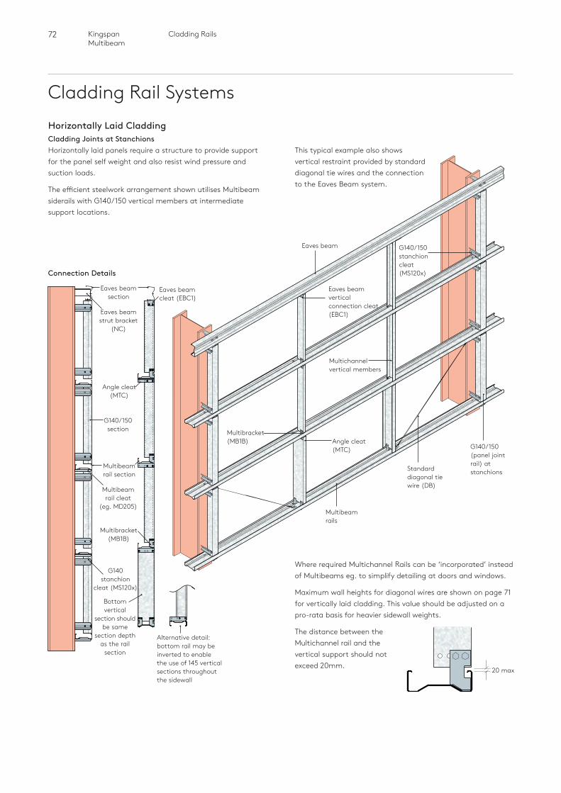
72 Cladding RailsKingspan Multibeam
Cladding Rail SystemsHorizontally Laid CladdingCladding Joints at StanchionsHorizontally laid panels require a structure to provide support for the panel self weight and also resist wind pressure and suction loads.
The efficient steelwork arrangement shown utilises Multibeam siderails with G140/150 vertical members at intermediate support locations.
Multibeam rails
Eaves beam
Standard diagonal tie wire (DB)
Angle cleat (MTC)
Eaves beam vertical connection cleat (EBC1)
Multichannel vertical members
G140/150 stanchion cleat (MS120x)
Multibracket (MB1B)
G140/150(panel joint rail) at stanchions
Alternative detail: bottom rail may be inverted to enable the use of 145 vertical sections throughout the sidewall
Where required Multichannel Rails can be ‘incorporated’ instead of Multibeams eg. to simplify detailing at doors and windows.
Maximum wall heights for diagonal wires are shown on page 71 for vertically laid cladding. This value should be adjusted on a pro-rata basis for heavier sidewall weights.
The distance between the Multichannel rail and the vertical support should not exceed 20mm.
Eaves beam strut bracket
(NC)
Multibracket (MB1B)
Multibeam rail cleat
(eg. MD205)
G140 stanchion
cleat (MS120x)
Eaves beam cleat (EBC1)
Eaves beam section
G140/150 section
Multibeam rail section
Bottom vertical
section should be same
section depth as the rail
section
Angle cleat (MTC)
Connection Details
20 max
This typical example also shows vertical restraint provided by standard diagonal tie wires and the connection to the Eaves Beam system.
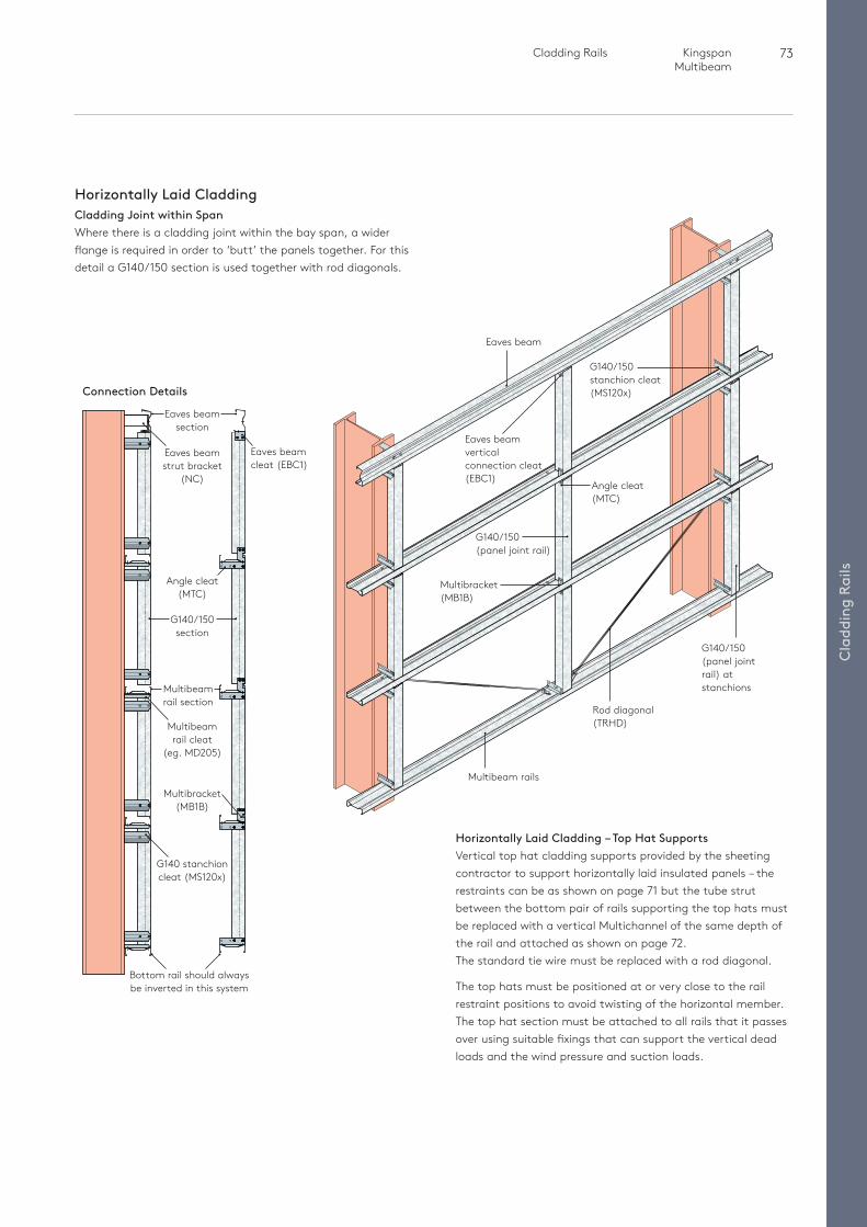
73 Cladding Rails Kingspan Multibeam
Cla
ddin
g Ra
ils
Eaves beam section
Multibeam rails
Eaves beam
Rod diagonal (TRHD)
Angle cleat (MTC)
Eaves beam vertical connection cleat (EBC1)
G140/150(panel joint rail)
G140/150 stanchion cleat (MS120x)
Multibracket (MB1B)
G140/150(panel joint rail) at stanchions
Horizontally Laid Cladding – Top Hat SupportsVertical top hat cladding supports provided by the sheeting contractor to support horizontally laid insulated panels – the restraints can be as shown on page 71 but the tube strut between the bottom pair of rails supporting the top hats must be replaced with a vertical Multichannel of the same depth of the rail and attached as shown on page 72. The standard tie wire must be replaced with a rod diagonal.
The top hats must be positioned at or very close to the rail restraint positions to avoid twisting of the horizontal member. The top hat section must be attached to all rails that it passes over using suitable fixings that can support the vertical dead loads and the wind pressure and suction loads.
Horizontally Laid CladdingCladding Joint within SpanWhere there is a cladding joint within the bay span, a wider flange is required in order to ‘butt’ the panels together. For this detail a G140/150 section is used together with rod diagonals.
Eaves beam strut bracket
(NC)
Multibracket (MB1B)
Multibeam rail cleat
(eg. MD205)
G140 stanchion cleat (MS120x)
Eaves beam cleat (EBC1)
G140/150 section
Bottom rail should always be inverted in this system
Multibeam rail section
Angle cleat (MTC)
Connection Details
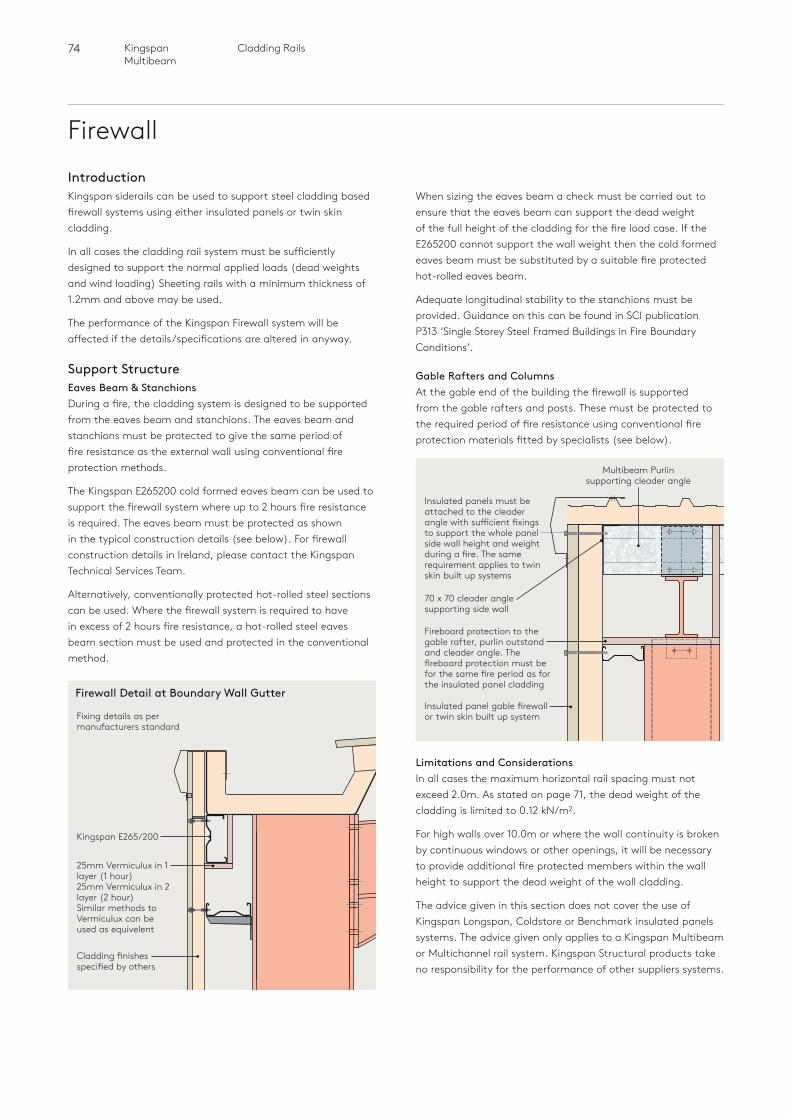
74 Cladding RailsKingspan Multibeam
FirewallIntroductionKingspan siderails can be used to support steel cladding based firewall systems using either insulated panels or twin skin cladding.
In all cases the cladding rail system must be sufficiently designed to support the normal applied loads (dead weights and wind loading) Sheeting rails with a minimum thickness of 1.2mm and above may be used.
The performance of the Kingspan Firewall system will be affected if the details/specifications are altered in anyway.
Support StructureEaves Beam & Stanchions During a fire, the cladding system is designed to be supported from the eaves beam and stanchions. The eaves beam and stanchions must be protected to give the same period of fire resistance as the external wall using conventional fire protection methods.
The Kingspan E265200 cold formed eaves beam can be used to support the firewall system where up to 2 hours fire resistance is required. The eaves beam must be protected as shown in the typical construction details (see below). For firewall construction details in Ireland, please contact the Kingspan Technical Services Team.
Alternatively, conventionally protected hot-rolled steel sections can be used. Where the firewall system is required to have in excess of 2 hours fire resistance, a hot-rolled steel eaves beam section must be used and protected in the conventional method.
Gable Rafters and Columns At the gable end of the building the firewall is supported from the gable rafters and posts. These must be protected to the required period of fire resistance using conventional fire protection materials fitted by specialists (see below).
When sizing the eaves beam a check must be carried out to ensure that the eaves beam can support the dead weight of the full height of the cladding for the fire load case. If the E265200 cannot support the wall weight then the cold formed eaves beam must be substituted by a suitable fire protected hot-rolled eaves beam.
Adequate longitudinal stability to the stanchions must be provided. Guidance on this can be found in SCI publication P313 ‘Single Storey Steel Framed Buildings in Fire Boundary Conditions’.
Limitations and Considerations In all cases the maximum horizontal rail spacing must not exceed 2.0m. As stated on page 71, the dead weight of the cladding is limited to 0.12 kN/m2.
For high walls over 10.0m or where the wall continuity is broken by continuous windows or other openings, it will be necessary to provide additional fire protected members within the wall height to support the dead weight of the wall cladding.
The advice given in this section does not cover the use of Kingspan Longspan, Coldstore or Benchmark insulated panels systems. The advice given only applies to a Kingspan Multibeam or Multichannel rail system. Kingspan Structural products take no responsibility for the performance of other suppliers systems.
Insulated panels must be attached to the cleader angle with sufficient fixings to support the whole panel side wall height and weight during a fire. The same requirement applies to twin skin built up systems
70 x 70 cleader angle supporting side wall
Multibeam Purlin supporting cleader angle
Fireboard protection to the gable rafter, purlin outstand and cleader angle. The fireboard protection must be for the same fire period as for the insulated panel cladding
Insulated panel gable firewall or twin skin built up system
Cladding finishes specified by others
25mm Vermiculux in 1 layer (1 hour)25mm Vermiculux in 2 layer (2 hour) Similar methods to Vermiculux can be used as equivelent
Kingspan E265/200
Fixing details as per manufacturers standard
Firewall Detail at Boundary Wall Gutter
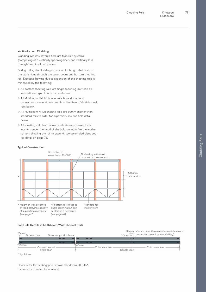
75 Cladding Rails Kingspan Multibeam
Cla
ddin
g Ra
ils
Vertically Laid CladdingCladding systems covered here are twin skin systems (comprising of a vertically spanning liner) and vertically laid through fixed insulated panels.
During a fire, the cladding acts as a diaphragm tied back to the stanchions through the eaves beam and bottom sheeting rail. Excessive bowing due to expansion of the sheeting rails is minimised by the following;
All bottom sheeting rails are single spanning (but can be sleeved) see typical construction below.
All Multibeam / Multichannel rails have slotted end connections, see end hole details in Multibeam/Multichannel rails below.
All Multibeam / Multichannel rails are 30mm shorter than standard rails to cater for expansion, see end hole detail below.
All sheeting rail cleat connection bolts must have plastic washers under the head of the bolt; during a fire the washer softens allowing the rail to expand, see assembled cleat and rail detail on page 76.
*
2000mm max centres
Fire protectedeaves beam E265200 All sheeting rails must
have slotted holes at ends
* Height of wall governed by load carrying capacity of supporting members (see page 71)
Standard rail strut system
All bottom rails must be single spanning but can be sleeved if necessary (see page 69)
Typical Construction
54x14mm slot23mm*
*Edge distance
20mmColumn centres Column centres Column centres
ø14mm holes (holes at intermediate column connection do not require slotting)Sleeve connection holes
40mm
single span Double span
100mm
50mm
End Hole Details in Multibeam/Multichannel Rails
Please refer to the Kingspan Firewall Handbook L00146A for construction details in Ireland.
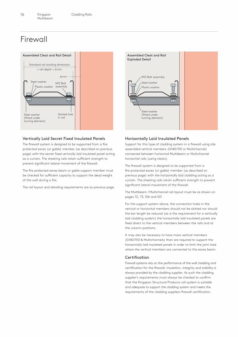
76 Cladding RailsKingspan Multibeam
Firewall
Horizontally Laid Insulated PanelsSupport for this type of cladding system in a firewall using site assembled vertical members (G140/150 or Multichannel) connected between horizontal Multibeam or Multichannel horizontal rails (using cleats).
The firewall system is designed to be supported from a fire protected eaves (or gable) member (as described on previous page) with the horizontally laid cladding acting as a curtain. The sheeting rails retain sufficient strength to prevent significant lateral movement of the firewall.
The Multibeam / Multichannel rail layout must be as shown on pages 72, 73, 106 and 107.
For the support system above, the connection holes in the vertical or horizontal members should not be slotted nor should the bar length be reduced (as is the requirement for a vertically laid cladding system) the horizontally laid insulated panels are fixed direct to the vertical members between the rails and at the column positions.
It may also be necessary to have more vertical members (G140/150 & Multichannels) than are required to support the horizontally laid insulated panels in order to limit the joint load where the vertical members are connected to the eaves beam.
Certification Firewall systems rely on the performance of the wall cladding and certification for the firewall; insulation, integrity and stability is always provided by the cladding supplier. As such the cladding supplier’s requirements must always be checked to confirm that the Kingspan Structural Products rail system is suitable and adequate to support the cladding system and meets the requirements of the cladding suppliers firewall certification.
Vertically Laid Secret Fixed Insulated PanelsThe firewall system is designed to be supported from a fire protected eaves (or gable) member (as described on previous page) with the secret fixed vertically laid insulated panel acting as a curtain. The sheeting rails retain sufficient strength to prevent significant lateral movement of the firewall.
The fire protected eaves beam or gable support member must be checked for sufficient capacity to support the dead weight of the wall during a fire.
The rail layout and detailing requirements are as previous page.
Assembled Cleat and Rail Detail Assembled Cleat and Rail Exploded Detail
6mm
Standard rail stooling dimension
= rail depth + 6mm
Slotted hole in rail
Steel washer (fitted under turning element)
Steel washer
Plastic washerM12 Bolt assembly Plastic washer
Steel washer
Steel washer (fitted under turning element)
M12 Bolt assembly
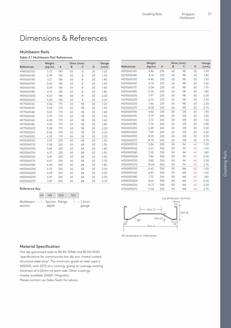
77 Cladding Rails Kingspan Multibeam
Cla
ddin
g Ra
ils
Dimensions & References
All dimensions in millimetres.
Dim B
30º
Dim A20
Dim C
32
Lip dimension nominal 15mm
Dim D
Weight Dims (mm) GaugeReferences (kg/m) A B C D (mm)M235065130 3.86 235 65 98 20 1.30M235065140 4.14 235 65 98 20 1.40M235065150 4.45 235 65 98 20 1.50M235065160 4.76 235 65 98 20 1.60M235065170 5.04 235 65 98 20 1.70M235065180 5.35 235 65 98 20 1.80M235065200 5.97 235 65 98 20 2.00M235065220 6.53 235 65 98 20 2.20M235065250 7.46 235 65 98 20 2.50M235065270 8.08 235 65 98 20 2.70M265065140 4.46 265 65 128 20 1.40M265065150 4.79 265 65 128 20 1.50M265065160 5.13 265 65 128 20 1.60M265065180 5.76 265 65 128 20 1.80M265065200 6.43 265 65 128 20 2.00M265065220 7.03 265 65 128 20 2.20M265065250 8.03 265 65 128 20 2.50M265065270 8.70 265 65 128 20 2.70M300090150 5.86 300 90 94 40 1.50M300090160 6.27 300 90 94 40 1.60M300090180 7.05 300 90 94 40 1.80M300090200 7.86 300 90 94 40 2.00M300090250 9.82 300 90 94 40 2.50M300090270 10.64 300 90 94 40 2.70M350090150 6.43 350 90 144 40 1.50M350090160 6.87 350 90 144 40 1.60M350090180 7.72 350 90 144 40 1.80M350090200 8.62 350 90 144 40 2.00M350090250 10.77 350 90 144 40 2.50M350090270 11.66 350 90 144 40 2.70
Multibeam RailsTable 3.1 Multibeam Rail References
Weight Dims (mm) GaugeReferences (kg/m) A B C D (mm)M145065120 2.75 145 65 8 20 1.20M145065130 2.99 145 65 8 20 1.30M145065140 3.21 145 65 8 20 1.40M145065150 3.45 145 65 8 20 1.50M145065160 3.69 145 65 8 20 1.60M145065180 4.15 145 65 8 20 1.80M145065200 4.63 145 65 8 20 2.00M145065220 5.06 145 65 8 20 2.20M175065120 3.02 175 65 38 20 1.20M175065130 3.29 175 65 38 20 1.30M175065140 3.52 175 65 38 20 1.40M175065150 3.79 175 65 38 20 1.50M175065160 4.05 175 65 38 20 1.60M175065180 4.55 175 65 38 20 1.80M175065200 5.08 175 65 38 20 2.00M175065220 5.56 175 65 38 20 2.20M175065250 6.35 175 65 38 20 2.50M205065120 3.29 205 65 68 20 1.20M205065130 3.58 205 65 68 20 1.30M205065140 3.84 205 65 68 20 1.40M205065150 4.13 205 65 68 20 1.50M205065160 4.41 205 65 68 20 1.60M205065170 4.67 205 65 68 20 1.70M205065180 4.96 205 65 68 20 1.80M205065200 5.53 205 65 68 20 2.00M205065220 6.05 205 65 68 20 2.20M205065250 6.91 205 65 68 20 2.50M205065270 7.49 205 65 68 20 2.70
M 145 065 120
Reference Key
Multibeam section
Section depth
Flange 1.2mm gauge
Material SpecificationHot dip galvanised steel to BS EN 10346 and BS EN 10143 ‘specifications for continuously hot dip zinc /metal coated structural steel strip’. The minimum grade of steel used is S450GD, with Z275 zinc coating, giving an average coating thickness of 0.02mm to each side. Other coatings maybe available (G600 / Magnelis). Please contact our Sales Team for advice.
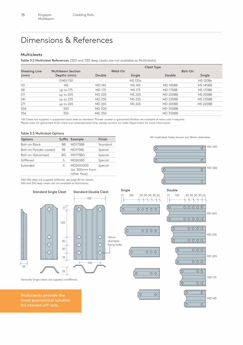
78 Cladding RailsKingspan Multibeam
Dimensions & References
MD 350
MD 300
MD 265
3017 105 30 30 30 26
MD 235
MD 205
MD 175
MD 145
Cleat TypeSheeting Line Multibeam Section Weld-On Bolt-On(mm) Depths (mm) Double Single Double Single– G140/150 – MS 120x – MS 120Bx 151 145 MD 145 MS 145 MD 145BB MS 145BB 181 up to 175 MD 175 MS 175 MD 175BB MS 175BB 211 up to 205 MD 205 MS 205 MD 205BB MS 205BB 241 up to 235 MD 235 MS 235 MD 235BB MS 235BB271 up to 265 MD 265 MS 265 MD 265BB MS 265BB306 300 MD 300 MD 300BB 356 350 MD 350 MD 350BB
*All Cleats are supplied in unpainted black steel as standard. Powder coated or galvanised finishes are available at extra cost if required. Please note, for galvanised finish there is an extended lead time, please contact our Sales Department for more information.
3017 105 30 30 30 26
MulticleatsTable 3:2 Multicleat References (300 and 350 deep cleats are not available as Multicleats)
All multicleat holes shown are 14mm diameter.
Double Single
Table 3:3 Multicleat Options
Options Suffix Example FinishBolt-on Black BB MD175BB StandardBolt-on Powder coated BE MD175BE SpecialBolt-on Galvanised BG MD175BG SpecialStiffened S MD265BS SpecialExtended X MD265X300 Special (ie; 300mm from
rafter face)
300/350 deep are supplied stiffened, see page 80 for details.300 and 350 deep cleats are not available as Multicleats.
14mm diameter fixing holes
Standard Double CleatStandard Single Cleat
26
35
30
30
17
105
150
35100
Generally Single cleats are supplied unstiffened.
Multicleats provide the most economical solution for stooled-off rails.
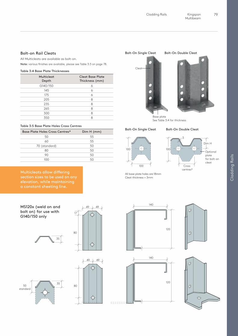
79 Cladding Rails Kingspan Multibeam
Cla
ddin
g Ra
ils
Bolt-on Rail CleatsAll Multicleats are available as bolt-on. Note: various finishes are available, please see Table 3:3 on page 78.
Table 3:4 Base Plate Thicknesses
Multicleat Cleat Base Plate Depth Thickness (mm) G140/150 6 145 6 175 6 205 8 235 8 265 8 300 8 350 8
Table 3:5 Base Plate Holes Cross Centres
Base Plate Holes Cross Centres* Dim H (mm) 50 55 60 55 70 (standard) 50 80 50 90 50 100 50
Bolt-On Single Cleat
3
Optional plate for bolt-on cleat
Dim H
100
Cross centres*
100
100
Bolt-On Double Cleat
All base plate holes are 18mmCleat thickness = 3mm
Cleat
Base plateSee Table 3:4 for thickness
Bolt-On Single Cleat Bolt-On Double Cleat
Multicleats allow differing section sizes to be used on any elevation, while maintaining a constant sheeting line.
MS120x (weld on and bolt on) for use with G140/150 only
80
49 49
35
35
49 49
80
140
120
17
50 standard
140
120
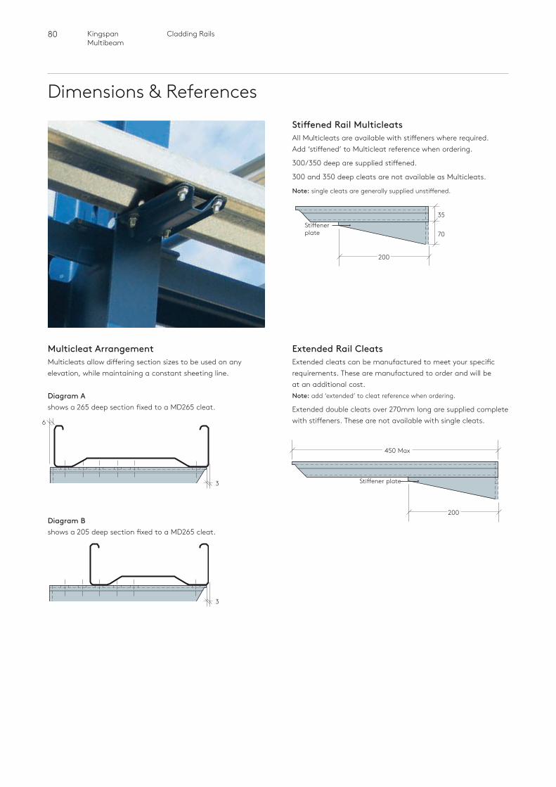
80 Cladding RailsKingspan Multibeam
Dimensions & References
Stiffener plate
200
70
35
Stiffened Rail MulticleatsAll Multicleats are available with stiffeners where required. Add ‘stiffened’ to Multicleat reference when ordering.
300/350 deep are supplied stiffened.
300 and 350 deep cleats are not available as Multicleats.
Note: single cleats are generally supplied unstiffened.
Multicleat ArrangementMulticleats allow differing section sizes to be used on any elevation, while maintaining a constant sheeting line.
450 Max
200
Stiffener plate3
3
Diagram Ashows a 265 deep section fixed to a MD265 cleat.
Diagram Bshows a 205 deep section fixed to a MD265 cleat.
6
Extended Rail CleatsExtended cleats can be manufactured to meet your specific requirements. These are manufactured to order and will be at an additional cost. Note: add ‘extended’ to cleat reference when ordering.
Extended double cleats over 270mm long are supplied complete with stiffeners. These are not available with single cleats.
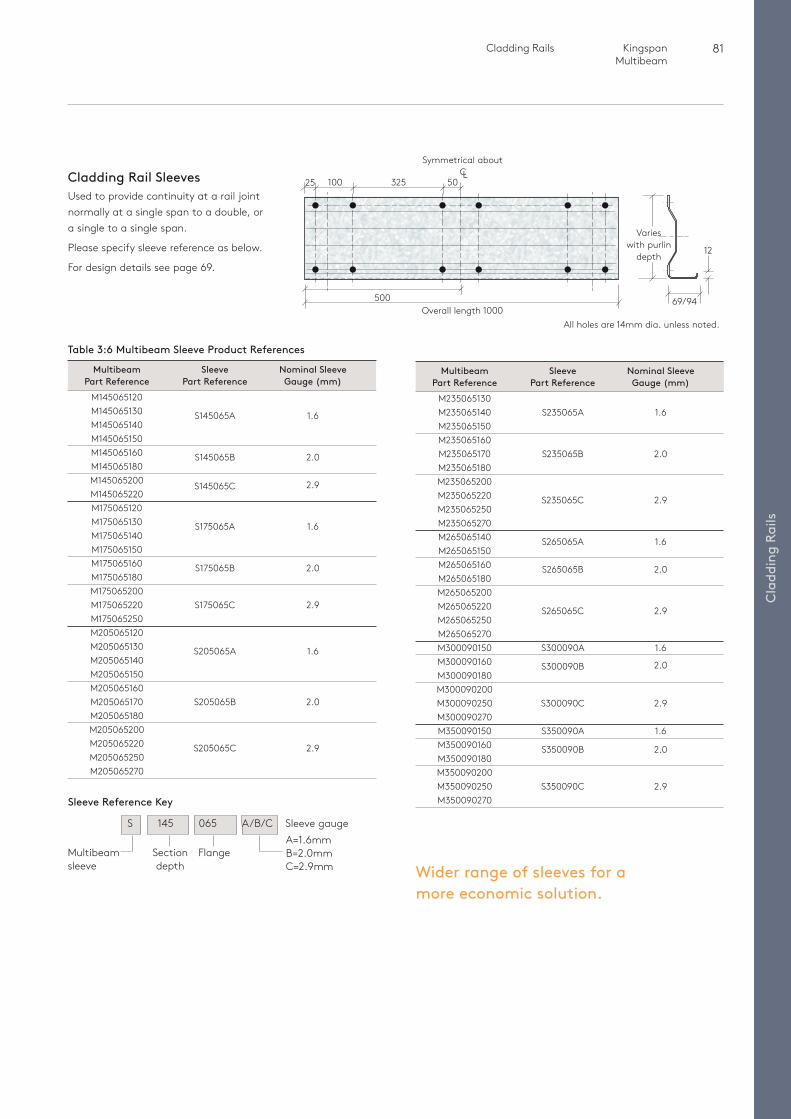
81 Cladding Rails Kingspan Multibeam
Cla
ddin
g Ra
ils
Wider range of sleeves for a more economic solution.
Cladding Rail SleevesUsed to provide continuity at a rail joint normally at a single span to a double, or a single to a single span.
Please specify sleeve reference as below.
For design details see page 69.
32510025 50
500Overall length 1000
Symmetrical about CL
All holes are 14mm dia. unless noted.
69/94
12
Varies with purlin
depth
Section depth
FlangeMultibeam sleeve
A=1.6mm B=2.0mm C=2.9mm
S 145 065 A/B/C Sleeve gauge
Sleeve Reference Key
Table 3:6 Multibeam Sleeve Product References
Multibeam Sleeve Nominal Sleeve Part Reference Part Reference Gauge (mm) M145065120 M145065130 S145065A 1.6 M145065140 M145065150 M145065160 S145065B 2.0 M145065180 M145065200 S145065C 2.9 M145065220 M175065120 M175065130 S175065A 1.6 M175065140 M175065150 M175065160 S175065B 2.0 M175065180 M175065200 M175065220 S175065C 2.9 M175065250 M205065120 M205065130 S205065A 1.6 M205065140 M205065150 M205065160 M205065170 S205065B 2.0 M205065180 M205065200 M205065220 S205065C 2.9 M205065250 M205065270
Multibeam Sleeve Nominal Sleeve Part Reference Part Reference Gauge (mm) M235065130 M235065140 S235065A 1.6 M235065150 M235065160 M235065170 S235065B 2.0 M235065180 M235065200 M235065220 S235065C 2.9 M235065250 M235065270 M265065140 S265065A 1.6 M265065150 M265065160 S265065B 2.0 M265065180 M265065200 M265065220 S265065C 2.9 M265065250 M265065270 M300090150 S300090A 1.6 M300090160 S300090B 2.0 M300090180 M300090200 M300090250 S300090C 2.9 M300090270 M350090150 S350090A 1.6 M350090160 S350090B 2.0 M350090180 M350090200 M350090250 S350090C 2.9 M350090270
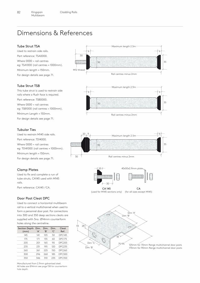
82 Cladding RailsKingspan Multibeam
Dimensions & References
Tube Strut TSAUsed to restrain side rails.
Part reference: TSA0000.
Where 0000 = rail centres eg: TSA1000 (rail centres = 1000mm).
Minimum length = 150mm.
For design details see page 71. Rail centres minus 2mm
3530
9
M12 thread
30
Maximum length 2.5m
9
Tube Strut TSBThis tube strut is used to restrain side rails where a flush face is required.
Part reference: TSB0000.
Where 0000 = rail centres eg: TSB1000 (rail centres = 1000mm).
Minimum Length = 150mm.
For design details see page 71.Rail centres minus 2mm
3530
9
Maximum length 2.5m
9
Rail centres minus 2mm
920 9
30
Tubular TiesUsed to restrain M145 side rails.
Part reference: TS14000.
Where 0000 = rail centres eg: TS141000 (rail centres = 1000mm).
Minimum length = 150mm.
For design details see page 71.
35
Clamp PlatesUsed to fix and complete a run of tube struts, CA145 used with M145 rails.
Part reference: CA145 / CA. CA 145(used for M145 sections only)
30
20
CA(for all sizes except M145)
40x50x2.9mm plate
Maximum length 2.5m
30
Door Post Cleat DPCUsed to connect a horizontal multibeam rail to a vertical multichannel when used to form a personnel door post. For connections into 300 and 350 deep sections cleats are supplied with 3no. Ø14mm counterform holes along the centreline.
Manufactured from 2.9mm galvanised steel. All holes are Ø14mm see page 138 for counterform hole depth.
Section Depth (mm)
Dim. ‘A’
Dim. ‘B’
Dim. ‘C’
Cleat Ref.
145 141 105 50 DPC145175 171 135 60 DPC175205 201 165 90 DPC205235 231 195 120 DPC235265 261 225 150 DPC265300 296 260 185 DPC300350 346 310 235 DPC350
Dim ‘A’Dim ‘B’
Dim ‘C’
Dim ‘B’75/95 125mm for 70mm flange multichannel door posts
170mm for 90mm flange multichannel door posts
18
2855
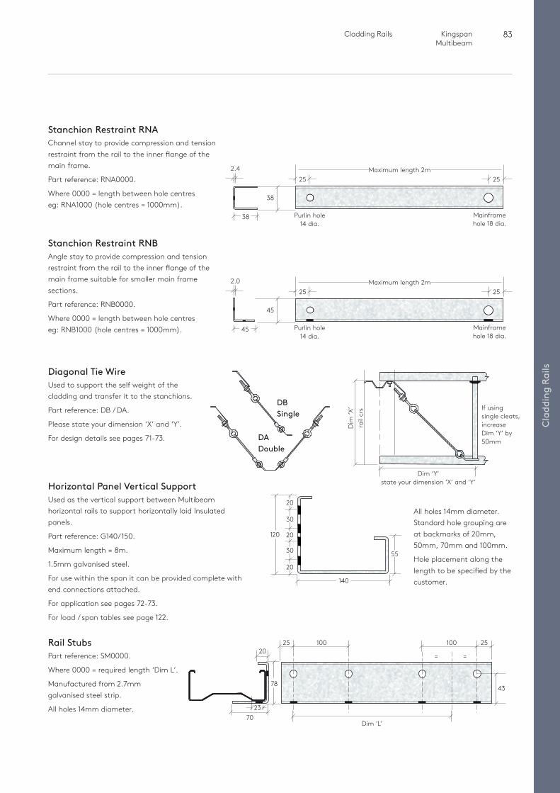
83 Cladding Rails Kingspan Multibeam
Cla
ddin
g Ra
ils
Stanchion Restraint RNAChannel stay to provide compression and tension restraint from the rail to the inner flange of the main frame.
Part reference: RNA0000.
Where 0000 = length between hole centres eg: RNA1000 (hole centres = 1000mm).
Rail StubsPart reference: SM0000.
Where 0000 = required length ‘Dim L’.
Manufactured from 2.7mm galvanised steel strip.
All holes 14mm diameter.
2025 25
= =
43
100
Dim ‘L’
100
7023
78
Horizontal Panel Vertical SupportUsed as the vertical support between Multibeam horizontal rails to support horizontally laid Insulated panels.
Part reference: G140/150.
Maximum length = 8m.
1.5mm galvanised steel.
For use within the span it can be provided complete with end connections attached.
For application see pages 72-73.
For load / span tables see page 122.
120
All holes 14mm diameter.Standard hole grouping are at backmarks of 20mm, 50mm, 70mm and 100mm.
Hole placement along the length to be specified by the customer.
Maximum length 2m2525
Purlin hole 14 dia.
Mainframe hole 18 dia.
45
2.0
45
Stanchion Restraint RNBAngle stay to provide compression and tension restraint from the rail to the inner flange of the main frame suitable for smaller main frame sections.
Part reference: RNB0000.
Where 0000 = length between hole centres eg: RNB1000 (hole centres = 1000mm).
Diagonal Tie WireUsed to support the self weight of the cladding and transfer it to the stanchions.
Part reference: DB / DA.
Please state your dimension ‘X’ and ‘Y’.
For design details see pages 71-73. DA Double
DB Single
Dim ‘Y’ state your dimension ‘X’ and ‘Y’
rail
crs
Dim
‘X’ If using
single cleats, increase Dim ‘Y’ by 50mm
55
140
20
30
20
30
20
25
Purlin hole 14 dia.
Mainframe hole 18 dia.
38
2.4
38
25Maximum length 2m
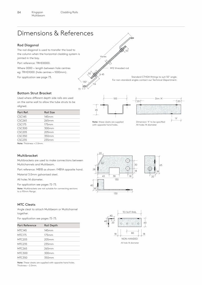
84 Cladding RailsKingspan Multibeam
Dimensions & ReferencesRod DiagonalThe rod diagonal is used to transfer the load to the column when the horizontal cladding system is jointed in the bay.
Part reference: TRHD0000.
Where 0000 = length between hole centres eg: TRHD1000 (hole centres = 1000mm).
For application see page 73.
Varies
4550
116
50
130˚
13
M12 threaded rod
Standard CTHDA fittings to suit 50˚ angle. For non-standard angles contact our Technical Department.
Bottom Strut BracketUsed where different depth side rails are used on the same wall to allow the tube struts to be aligned.
Part Ref. Rail Size CSC145 145mm CSC265 265mmCSC175 175mm CSC300 300mmCSC205 205mm CSC350 350mmCSC235 235mmNote: Thickness = 2.0mm.
Note: these cleats are supplied with opposite hand holes.
10020 20
Dim ‘A’
45
‘X’Dimension ‘X’ to be specifiedAll holes 14 diameter
MTC CleatsAngle cleat to attach Multibeam or Multichannel together.
For application see pages 72-73.
Part Reference Rail Depth
MTC145 145mm
MTC175 175mm
MTC205 205mm
MTC235 235mm
MTC265 265mm
MTC300 300mm
MTC350 350mm
Note: These cleats are supplied with opposite hand holes.Thickness = 2.0mm.
40
1818 80
TO SUIT RAIL
NON-HANDED
6040
All hole 14 diameter
20
MultibracketMultibrackets are used to make connections between Multichannels and Multibeam.
Part reference: MB1B as shown / MB1A opposite hand.
Material 3.0mm galvanised steel.
All holes 14 diameter.
For application see pages 72-73.Note: Multibrackets are not suitable for connecting sections to a 90mm flange.
65
18
20
1840
130
30
38
30˚
28
130
18
1843
20
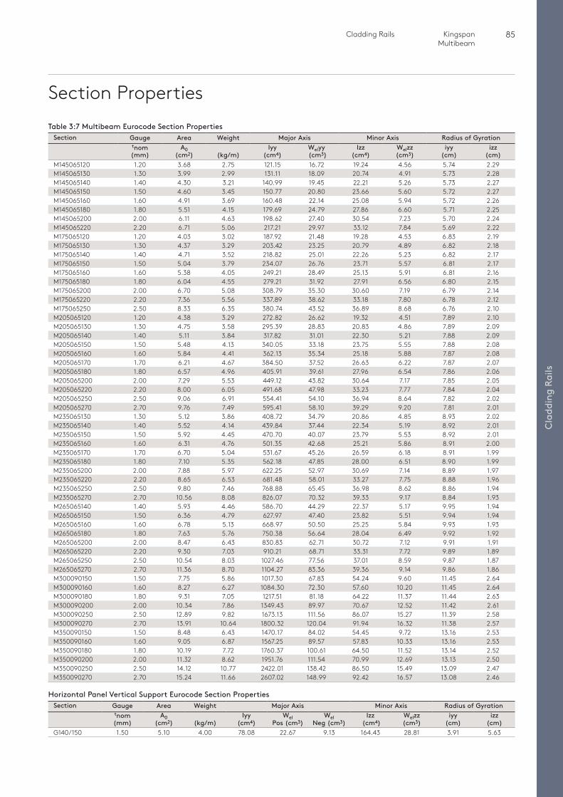
85 Cladding Rails Kingspan Multibeam
Cla
ddin
g Ra
ils
Section PropertiesTable 3:7 Multibeam Eurocode Section Properties
Section Gauge Area Weight Major Axis Minor Axis Radius of Gyrationtnom (mm)
A0 (cm2)
(kg/m)
Iyy (cm4)
Welyy (cm3)
Izz (cm4)
Welzz (cm3)
iyy (cm)
izz (cm)
M145065120 1.20 3.68 2.75 121.15 16.72 19.24 4.56 5.74 2.29M145065130 1.30 3.99 2.99 131.11 18.09 20.74 4.91 5.73 2.28M145065140 1.40 4.30 3.21 140.99 19.45 22.21 5.26 5.73 2.27M145065150 1.50 4.60 3.45 150.77 20.80 23.66 5.60 5.72 2.27M145065160 1.60 4.91 3.69 160.48 22.14 25.08 5.94 5.72 2.26M145065180 1.80 5.51 4.15 179.69 24.79 27.86 6.60 5.71 2.25M145065200 2.00 6.11 4.63 198.62 27.40 30.54 7.23 5.70 2.24M145065220 2.20 6.71 5.06 217.21 29.97 33.12 7.84 5.69 2.22M175065120 1.20 4.03 3.02 187.92 21.48 19.28 4.53 6.83 2.19M175065130 1.30 4.37 3.29 203.42 23.25 20.79 4.89 6.82 2.18M175065140 1.40 4.71 3.52 218.82 25.01 22.26 5.23 6.82 2.17M175065150 1.50 5.04 3.79 234.07 26.76 23.71 5.57 6.81 2.17M175065160 1.60 5.38 4.05 249.21 28.49 25.13 5.91 6.81 2.16M175065180 1.80 6.04 4.55 279.21 31.92 27.91 6.56 6.80 2.15M175065200 2.00 6.70 5.08 308.79 35.30 30.60 7.19 6.79 2.14M175065220 2.20 7.36 5.56 337.89 38.62 33.18 7.80 6.78 2.12M175065250 2.50 8.33 6.35 380.74 43.52 36.89 8.68 6.76 2.10M205065120 1.20 4.38 3.29 272.82 26.62 19.32 4.51 7.89 2.10M205065130 1.30 4.75 3.58 295.39 28.83 20.83 4.86 7.89 2.09M205065140 1.40 5.11 3.84 317.82 31.01 22.30 5.21 7.88 2.09M205065150 1.50 5.48 4.13 340.05 33.18 23.75 5.55 7.88 2.08M205065160 1.60 5.84 4.41 362.13 35.34 25.18 5.88 7.87 2.08M205065170 1.70 6.21 4.67 384.50 37.52 26.63 6.22 7.87 2.07M205065180 1.80 6.57 4.96 405.91 39.61 27.96 6.54 7.86 2.06M205065200 2.00 7.29 5.53 449.12 43.82 30.64 7.17 7.85 2.05M205065220 2.20 8.00 6.05 491.68 47.98 33.23 7.77 7.84 2.04M205065250 2.50 9.06 6.91 554.41 54.10 36.94 8.64 7.82 2.02M205065270 2.70 9.76 7.49 595.41 58.10 39.29 9.20 7.81 2.01M235065130 1.30 5.12 3.86 408.72 34.79 20.86 4.85 8.93 2.02M235065140 1.40 5.52 4.14 439.84 37.44 22.34 5.19 8.92 2.01M235065150 1.50 5.92 4.45 470.70 40.07 23.79 5.53 8.92 2.01M235065160 1.60 6.31 4.76 501.35 42.68 25.21 5.86 8.91 2.00M235065170 1.70 6.70 5.04 531.67 45.26 26.59 6.18 8.91 1.99M235065180 1.80 7.10 5.35 562.18 47.85 28.00 6.51 8.90 1.99M235065200 2.00 7.88 5.97 622.25 52.97 30.69 7.14 8.89 1.97M235065220 2.20 8.65 6.53 681.48 58.01 33.27 7.75 8.88 1.96M235065250 2.50 9.80 7.46 768.88 65.45 36.98 8.62 8.86 1.94M235065270 2.70 10.56 8.08 826.07 70.32 39.33 9.17 8.84 1.93M265065140 1.40 5.93 4.46 586.70 44.29 22.37 5.17 9.95 1.94M265065150 1.50 6.36 4.79 627.97 47.40 23.82 5.51 9.94 1.94M265065160 1.60 6.78 5.13 668.97 50.50 25.25 5.84 9.93 1.93M265065180 1.80 7.63 5.76 750.38 56.64 28.04 6.49 9.92 1.92M265065200 2.00 8.47 6.43 830.83 62.71 30.72 7.12 9.91 1.91M265065220 2.20 9.30 7.03 910.21 68.71 33.31 7.72 9.89 1.89M265065250 2.50 10.54 8.03 1027.46 77.56 37.01 8.59 9.87 1.87M265065270 2.70 11.36 8.70 1104.27 83.36 39.36 9.14 9.86 1.86M300090150 1.50 7.75 5.86 1017.30 67.83 54.24 9.60 11.45 2.64M300090160 1.60 8.27 6.27 1084.30 72.30 57.60 10.20 11.45 2.64M300090180 1.80 9.31 7.05 1217.51 81.18 64.22 11.37 11.44 2.63M300090200 2.00 10.34 7.86 1349.43 89.97 70.67 12.52 11.42 2.61M300090250 2.50 12.89 9.82 1673.13 111.56 86.07 15.27 11.39 2.58M300090270 2.70 13.91 10.64 1800.32 120.04 91.94 16.32 11.38 2.57M350090150 1.50 8.48 6.43 1470.17 84.02 54.45 9.72 13.16 2.53M350090160 1.60 9.05 6.87 1567.25 89.57 57.83 10.33 13.16 2.53M350090180 1.80 10.19 7.72 1760.37 100.61 64.50 11.52 13.14 2.52M350090200 2.00 11.32 8.62 1951.76 111.54 70.99 12.69 13.13 2.50M350090250 2.50 14.12 10.77 2422.01 138.42 86.50 15.49 13.09 2.47M350090270 2.70 15.24 11.66 2607.02 148.99 92.42 16.57 13.08 2.46
Horizontal Panel Vertical Support Eurocode Section PropertiesSection Gauge Area Weight Major Axis Minor Axis Radius of Gyration
tnom (mm)
A0 (cm2)
(kg/m)
Iyy (cm4)
Wel Pos (cm3)
Wel Neg (cm3)
Izz (cm4)
Welzz (cm3)
iyy (cm)
izz (cm)
G140/150 1.50 5.10 4.00 78.08 22.67 9.13 164.43 28.81 3.91 5.63
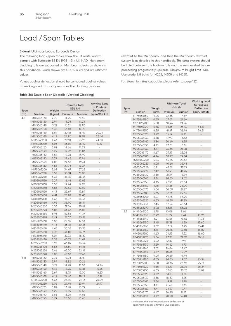
86 Cladding RailsKingspan Multibeam
Load / Span TablesSiderail Ultimate Loads: Eurocode DesignThe following load / span tables show the ultimate load to comply with Eurocode BS EN 1993-1-3 + UK NAD. Multibeam cladding rails are supported on Multibeam cleats as shown in this handbook. Loads shown are UDL’S in kN and are ultimate values.
Values against deflection should be compared against values at working load. Capacity assumes the cladding provides
restraint to the Multibeam, and that the Multibeam restraint system is as detailed in this handbook. The strut system should be fitted between the bottom rails and the rails levelled before proceeding progressively upwards. Maximum height limit 10m. Use grade 8.8 bolts for M265, M300 and M350.
For Stanchion Stay capacities please refer to page 122.
Table 3:8 Double Span Siderails (Vertical Cladding)
Span (m) Section
Weight (kg/m)
Ultimate Total UDL kN
Working Load to Produce Deflection
Span/150 kNPressure Suction4.5 M145065120 2.75 11.95 9.33 -
M145065130 2.99 14.04 11.23 -M145065140 3.21 16.21 12.96 -M145065150 3.45 18.40 14.72 -M145065160 3.69 20.61 16.49 20.04M145065180 4.15 24.96 19.97 22.44M145065200 4.63 29.10 23.28 24.80M145065220 5.06 33.02 26.42 27.12M175065120 3.02 14.66 11.73 -M175065130 3.29 17.29 13.83 -M175065140 3.52 19.98 15.99 -M175065150 3.79 22.45 17.96 -M175065160 4.05 24.52 19.61 -M175065180 4.55 29.74 23.34 -M175065200 5.08 34.07 27.25 -M175065220 5.56 38.74 31.00 -M175065250 6.35 45.42 36.34 -M205065120 3.29 16.44 13.02 -M205065130 3.58 19.44 14.98 -M205065140 3.84 22.53 17.40 -M205065150 4.13 25.67 19.89 -M205065160 4.41 28.82 22.40 -M205065170 4.67 31.97 24.55 -M205065180 4.96 33.90 26.47 -M205065200 5.53 39.16 30.69 -M205065220 6.05 44.66 35.08 -M205065250 6.91 52.52 41.37 -M205065270 7.49 57.57 45.42 -M235065130 3.86 22.89 17.58 -M235065140 4.14 26.61 20.35 -M235065150 4.45 30.38 23.35 -M235065160 4.76 34.07 26.73 -M235065170 5.04 37.23 28.82 -M235065180 5.35 40.75 31.47 -M235065200 5.97 46.89 36.54 -M235065220 6.53 53.69 44.28 -M235065250 7.46 63.30 52.41 -M235065270 8.08 69.52 57.66 -
5.0 M145065120 2.75 10.94 8.75 -M145065130 2.99 12.82 10.26 -M145065140 3.21 14.78 11.82 14.26M145065150 3.45 16.76 13.41 15.25M145065160 3.69 18.75 15.00 16.23M145065180 4.15 22.67 18.13 18.17M145065200 4.63 26.39 21.12 20.09M145065220 5.06 29.93 23.94 21.97M175065120 3.02 13.48 10.79 -M175065130 3.29 15.85 12.68 -M175065140 3.52 18.28 14.63 -M175065150 3.79 20.50 16.40 -
Span (m) Section
Weight (kg/m)
Ultimate Total UDL kN
Working Load to Produce Deflection
Span/150 kNPressure SuctionM175065160 4.05 22.36 17.89 -M175065180 4.55 27.07 21.66 -M175065200 5.08 30.96 24.76 -M175065220 5.56 35.16 28.13 34.17M175065250 6.35 41.17 32.94 38.51M205065120 3.29 15.19 12.15 -M205065130 3.58 17.90 14.32 -M205065140 3.84 20.69 16.55 -M205065150 4.13 23.51 18.81 -M205065160 4.41 26.35 21.08 -M205065170 4.67 29.19 23.02 -M205065180 4.96 30.92 24.74 -M205065200 5.53 35.65 28.52 -M205065220 6.05 40.60 32.48 -M205065250 6.91 47.67 38.13 -M205065270 7.49 52.21 41.76 -M235065130 3.86 21.17 16.94 -M235065140 4.14 24.53 19.62 -M235065150 4.45 27.93 22.34 -M235065160 4.76 31.25 25.00 -M235065170 5.04 34.09 27.27 -M235065180 5.35 37.26 29.65 -M235065200 5.97 42.78 34.20 -M235065220 6.53 48.89 41.25 -M235065250 7.46 57.54 48.54 -M235065270 8.08 63.13 53.26 -
5.5 M145065120 2.75 10.08 8.06 -M145065130 2.99 11.79 9.44 10.96M145065140 3.21 13.58 10.86 11.78M145065150 3.45 15.38 12.30 12.60M145065160 3.69 17.19 13.75 13.41M145065180 4.15 20.76 16.60 15.02M145065200 4.63 24.15 19.32 16.60M145065220 5.06 27.36 21.89 18.16M175065120 3.02 12.47 9.97 -M175065130 3.29 14.62 11.70 -M175065140 3.52 16.84 13.47 -M175065150 3.79 18.86 15.09 -M175065160 4.05 20.55 16.44 -M175065180 4.55 24.83 19.87 23.34M175065200 5.08 28.36 22.69 25.81M175065220 5.56 32.19 25.75 28.24M175065250 6.35 37.65 30.12 31.82M205065120 3.29 14.10 11.28 -M205065130 3.58 16.57 13.25 -M205065140 3.84 19.11 15.29 -M205065150 4.13 21.68 17.35 -M205065160 4.41 24.27 19.41 -M205065170 4.67 26.85 21.17 -M175065150 3.79 20.50 16.40 -
- indicates the load to produce a deflection of span/150 exceeds ultimate UDL capacity
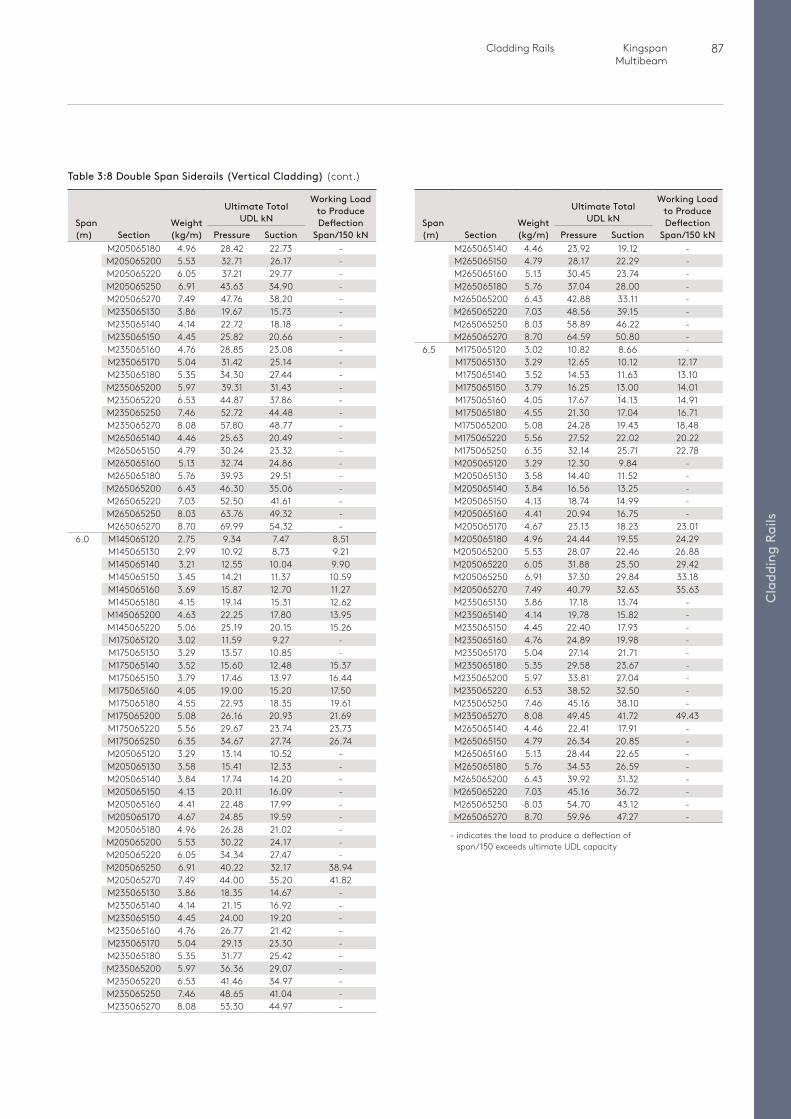
87 Cladding Rails Kingspan Multibeam
Cla
ddin
g Ra
ils
Span (m) Section
Weight (kg/m)
Ultimate Total UDL kN
Working Load to Produce Deflection
Span/150 kNPressure SuctionM265065140 4.46 23.92 19.12 -M265065150 4.79 28.17 22.29 -M265065160 5.13 30.45 23.74 -M265065180 5.76 37.04 28.00 -M265065200 6.43 42.88 33.11 -M265065220 7.03 48.56 39.15 -M265065250 8.03 58.89 46.22 -M265065270 8.70 64.59 50.80 -
6.5 M175065120 3.02 10.82 8.66 -M175065130 3.29 12.65 10.12 12.17M175065140 3.52 14.53 11.63 13.10M175065150 3.79 16.25 13.00 14.01M175065160 4.05 17.67 14.13 14.91M175065180 4.55 21.30 17.04 16.71M175065200 5.08 24.28 19.43 18.48M175065220 5.56 27.52 22.02 20.22M175065250 6.35 32.14 25.71 22.78M205065120 3.29 12.30 9.84 -M205065130 3.58 14.40 11.52 -M205065140 3.84 16.56 13.25 -M205065150 4.13 18.74 14.99 -M205065160 4.41 20.94 16.75 -M205065170 4.67 23.13 18.23 23.01M205065180 4.96 24.44 19.55 24.29M205065200 5.53 28.07 22.46 26.88M205065220 6.05 31.88 25.50 29.42M205065250 6.91 37.30 29.84 33.18M205065270 7.49 40.79 32.63 35.63M235065130 3.86 17.18 13.74 -M235065140 4.14 19.78 15.82 -M235065150 4.45 22.40 17.93 -M235065160 4.76 24.89 19.98 -M235065170 5.04 27.14 21.71 -M235065180 5.35 29.58 23.67 -M235065200 5.97 33.81 27.04 -M235065220 6.53 38.52 32.50 -M235065250 7.46 45.16 38.10 -M235065270 8.08 49.45 41.72 49.43M265065140 4.46 22.41 17.91 -M265065150 4.79 26.34 20.85 -M265065160 5.13 28.44 22.65 -M265065180 5.76 34.53 26.59 -M265065200 6.43 39.92 31.32 -M265065220 7.03 45.16 36.72 -M265065250 8.03 54.70 43.12 -M265065270 8.70 59.96 47.27 -
Table 3:8 Double Span Siderails (Vertical Cladding) (cont.)
- indicates the load to produce a deflection of span/150 exceeds ultimate UDL capacity
Span (m) Section
Weight (kg/m)
Ultimate Total UDL kN
Working Load to Produce Deflection
Span/150 kNPressure SuctionM205065180 4.96 28.42 22.73 -M205065200 5.53 32.71 26.17 -M205065220 6.05 37.21 29.77 -M205065250 6.91 43.63 34.90 -M205065270 7.49 47.76 38.20 -M235065130 3.86 19.67 15.73 -M235065140 4.14 22.72 18.18 -M235065150 4.45 25.82 20.66 -M235065160 4.76 28.85 23.08 -M235065170 5.04 31.42 25.14 -M235065180 5.35 34.30 27.44 -M235065200 5.97 39.31 31.43 -M235065220 6.53 44.87 37.86 -M235065250 7.46 52.72 44.48 -M235065270 8.08 57.80 48.77 -M265065140 4.46 25.63 20.49 -M265065150 4.79 30.24 23.32 -M265065160 5.13 32.74 24.86 -M265065180 5.76 39.93 29.51 -M265065200 6.43 46.30 35.06 -M265065220 7.03 52.50 41.61 -M265065250 8.03 63.76 49.32 -M265065270 8.70 69.99 54.32 -
6.0 M145065120 2.75 9.34 7.47 8.51M145065130 2.99 10.92 8.73 9.21M145065140 3.21 12.55 10.04 9.90M145065150 3.45 14.21 11.37 10.59M145065160 3.69 15.87 12.70 11.27M145065180 4.15 19.14 15.31 12.62M145065200 4.63 22.25 17.80 13.95M145065220 5.06 25.19 20.15 15.26M175065120 3.02 11.59 9.27 -M175065130 3.29 13.57 10.85 -M175065140 3.52 15.60 12.48 15.37M175065150 3.79 17.46 13.97 16.44M175065160 4.05 19.00 15.20 17.50M175065180 4.55 22.93 18.35 19.61M175065200 5.08 26.16 20.93 21.69M175065220 5.56 29.67 23.74 23.73M175065250 6.35 34.67 27.74 26.74M205065120 3.29 13.14 10.52 -M205065130 3.58 15.41 12.33 -M205065140 3.84 17.74 14.20 -M205065150 4.13 20.11 16.09 -M205065160 4.41 22.48 17.99 -M205065170 4.67 24.85 19.59 -M205065180 4.96 26.28 21.02 -M205065200 5.53 30.22 24.17 -M205065220 6.05 34.34 27.47 -M205065250 6.91 40.22 32.17 38.94M205065270 7.49 44.00 35.20 41.82M235065130 3.86 18.35 14.67 -M235065140 4.14 21.15 16.92 -M235065150 4.45 24.00 19.20 -M235065160 4.76 26.77 21.42 -M235065170 5.04 29.13 23.30 -M235065180 5.35 31.77 25.42 -M235065200 5.97 36.36 29.07 -M235065220 6.53 41.46 34.97 -M235065250 7.46 48.65 41.04 -M235065270 8.08 53.30 44.97 -
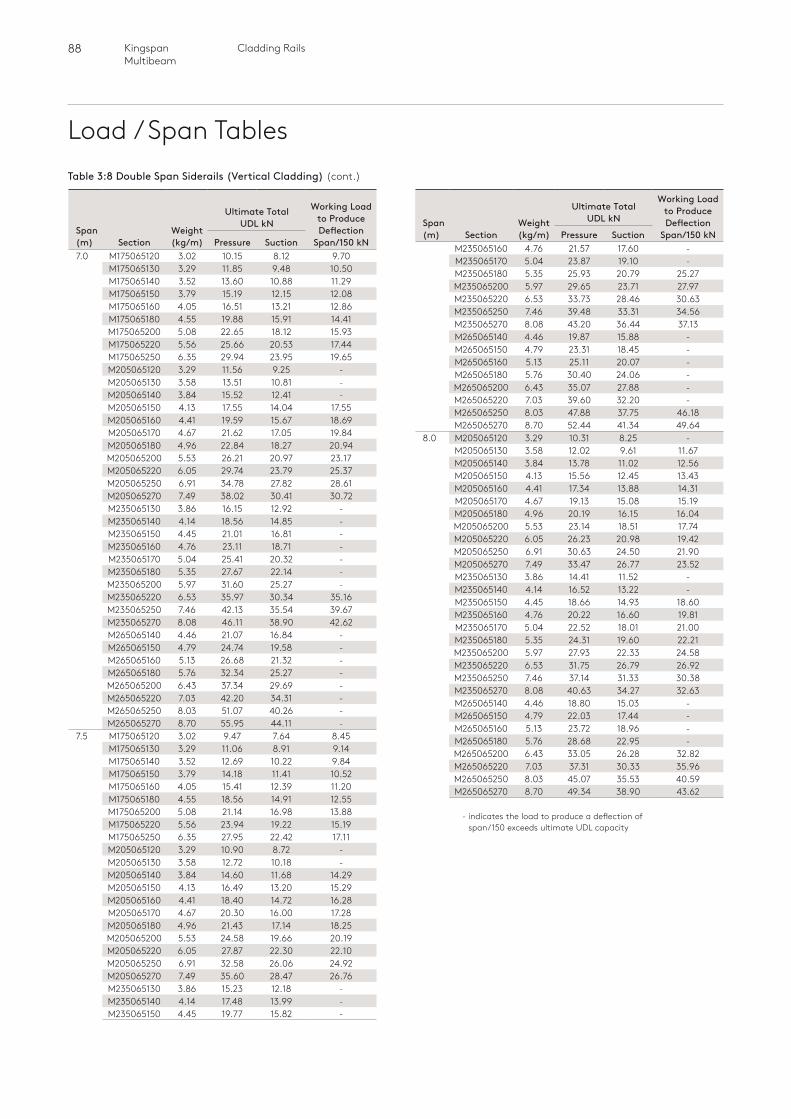
88 Cladding RailsKingspan Multibeam
Load / Span Tables
Span (m) Section
Weight (kg/m)
Ultimate Total UDL kN
Working Load to Produce Deflection
Span/150 kNPressure SuctionM235065160 4.76 21.57 17.60 -M235065170 5.04 23.87 19.10 -M235065180 5.35 25.93 20.79 25.27M235065200 5.97 29.65 23.71 27.97M235065220 6.53 33.73 28.46 30.63M235065250 7.46 39.48 33.31 34.56M235065270 8.08 43.20 36.44 37.13M265065140 4.46 19.87 15.88 -M265065150 4.79 23.31 18.45 -M265065160 5.13 25.11 20.07 -M265065180 5.76 30.40 24.06 -M265065200 6.43 35.07 27.88 -M265065220 7.03 39.60 32.20 -M265065250 8.03 47.88 37.75 46.18M265065270 8.70 52.44 41.34 49.64
8.0 M205065120 3.29 10.31 8.25 -M205065130 3.58 12.02 9.61 11.67M205065140 3.84 13.78 11.02 12.56M205065150 4.13 15.56 12.45 13.43M205065160 4.41 17.34 13.88 14.31M205065170 4.67 19.13 15.08 15.19M205065180 4.96 20.19 16.15 16.04M205065200 5.53 23.14 18.51 17.74M205065220 6.05 26.23 20.98 19.42M205065250 6.91 30.63 24.50 21.90M205065270 7.49 33.47 26.77 23.52M235065130 3.86 14.41 11.52 -M235065140 4.14 16.52 13.22 -M235065150 4.45 18.66 14.93 18.60M235065160 4.76 20.22 16.60 19.81M235065170 5.04 22.52 18.01 21.00M235065180 5.35 24.31 19.60 22.21M235065200 5.97 27.93 22.33 24.58M235065220 6.53 31.75 26.79 26.92M235065250 7.46 37.14 31.33 30.38M235065270 8.08 40.63 34.27 32.63M265065140 4.46 18.80 15.03 -M265065150 4.79 22.03 17.44 -M265065160 5.13 23.72 18.96 -M265065180 5.76 28.68 22.95 -M265065200 6.43 33.05 26.28 32.82M265065220 7.03 37.31 30.33 35.96M265065250 8.03 45.07 35.53 40.59M265065270 8.70 49.34 38.90 43.62
Table 3:8 Double Span Siderails (Vertical Cladding) (cont.)
- indicates the load to produce a deflection of span/150 exceeds ultimate UDL capacity
Span (m) Section
Weight (kg/m)
Ultimate Total UDL kN
Working Load to Produce Deflection
Span/150 kNPressure Suction7.0 M175065120 3.02 10.15 8.12 9.70
M175065130 3.29 11.85 9.48 10.50M175065140 3.52 13.60 10.88 11.29M175065150 3.79 15.19 12.15 12.08M175065160 4.05 16.51 13.21 12.86M175065180 4.55 19.88 15.91 14.41M175065200 5.08 22.65 18.12 15.93M175065220 5.56 25.66 20.53 17.44M175065250 6.35 29.94 23.95 19.65M205065120 3.29 11.56 9.25 -M205065130 3.58 13.51 10.81 -M205065140 3.84 15.52 12.41 -M205065150 4.13 17.55 14.04 17.55M205065160 4.41 19.59 15.67 18.69M205065170 4.67 21.62 17.05 19.84M205065180 4.96 22.84 18.27 20.94M205065200 5.53 26.21 20.97 23.17M205065220 6.05 29.74 23.79 25.37M205065250 6.91 34.78 27.82 28.61M205065270 7.49 38.02 30.41 30.72M235065130 3.86 16.15 12.92 -M235065140 4.14 18.56 14.85 -M235065150 4.45 21.01 16.81 -M235065160 4.76 23.11 18.71 -M235065170 5.04 25.41 20.32 -M235065180 5.35 27.67 22.14 -M235065200 5.97 31.60 25.27 -M235065220 6.53 35.97 30.34 35.16M235065250 7.46 42.13 35.54 39.67M235065270 8.08 46.11 38.90 42.62M265065140 4.46 21.07 16.84 -M265065150 4.79 24.74 19.58 -M265065160 5.13 26.68 21.32 -M265065180 5.76 32.34 25.27 -M265065200 6.43 37.34 29.69 -M265065220 7.03 42.20 34.31 -M265065250 8.03 51.07 40.26 -M265065270 8.70 55.95 44.11 -
7.5 M175065120 3.02 9.47 7.64 8.45M175065130 3.29 11.06 8.91 9.14M175065140 3.52 12.69 10.22 9.84M175065150 3.79 14.18 11.41 10.52M175065160 4.05 15.41 12.39 11.20M175065180 4.55 18.56 14.91 12.55M175065200 5.08 21.14 16.98 13.88M175065220 5.56 23.94 19.22 15.19M175065250 6.35 27.95 22.42 17.11M205065120 3.29 10.90 8.72 -M205065130 3.58 12.72 10.18 -M205065140 3.84 14.60 11.68 14.29M205065150 4.13 16.49 13.20 15.29M205065160 4.41 18.40 14.72 16.28M205065170 4.67 20.30 16.00 17.28M205065180 4.96 21.43 17.14 18.25M205065200 5.53 24.58 19.66 20.19M205065220 6.05 27.87 22.30 22.10M205065250 6.91 32.58 26.06 24.92M205065270 7.49 35.60 28.47 26.76M235065130 3.86 15.23 12.18 -M235065140 4.14 17.48 13.99 -M235065150 4.45 19.77 15.82 -
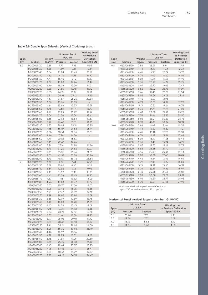
89 Cladding Rails Kingspan Multibeam
Cla
ddin
g Ra
ilsSpan (m)
Ultimate Total UDL kN
Working Load to Produce Deflection
Span/150 kNPressure Suction3.0 23.44 9.21 9.103.5 19.66 7.72 6.694.0 16.73 6.58 5.124.5 14.33 6.68 4.05
Table 3:8 Double Span Siderails (Vertical Cladding) (cont.)
- indicates the load to produce a deflection of span/150 exceeds ultimate UDL capacity
Span (m) Section
Weight (kg/m)
Ultimate Total UDL kN
Working Load to Produce Deflection
Span/150 kNPressure Suction8.5 M205065120 3.29 9.77 7.82 9.55
M205065130 3.58 11.39 9.11 10.34M205065140 3.84 13.04 10.43 11.12M205065150 4.13 14.72 11.78 11.90M205065160 4.41 16.40 13.12 12.67M205065170 4.67 18.08 14.26 13.46M205065180 4.96 19.08 15.26 14.21M205065200 5.53 21.85 17.48 15.72M205065220 6.05 24.76 19.81 17.21M205065250 6.91 28.91 23.12 19.40M205065270 7.49 31.57 25.26 20.84M235065130 3.86 13.66 10.93 -M235065140 4.14 15.66 12.53 15.39M235065150 4.45 17.68 14.14 16.47M235065160 4.76 19.03 15.72 17.54M235065170 5.04 21.30 17.04 18.61M235065180 5.35 22.88 18.54 19.67M235065200 5.97 26.40 21.11 21.78M235065220 6.53 29.99 25.31 23.85M235065250 7.46 35.07 29.58 26.91M235065270 8.08 38.34 32.35 28.91M265065140 4.46 17.84 14.26 -M265065150 4.79 20.88 16.53 -M265065160 5.13 22.47 17.96 -M265065180 5.76 27.14 21.89 26.26M265065200 6.43 31.26 24.85 29.07M265065220 7.03 35.26 28.66 31.85M265065250 8.03 42.57 33.56 35.96M265065270 8.70 46.59 36.73 38.64
9.0 M205065120 3.29 9.29 7.44 8.52M205065130 3.58 10.82 8.65 9.22M205065140 3.84 12.38 9.91 9.92M205065150 4.13 13.97 11.18 10.61M205065160 4.41 15.56 12.45 11.30M205065170 4.67 17.15 13.52 12.00M205065180 4.96 18.08 14.47 12.67M205065200 5.53 20.70 16.56 14.02M205065220 6.05 23.45 18.76 15.35M205065250 6.91 27.37 21.89 17.31M205065270 7.49 29.88 23.90 18.59M235065130 3.86 12.99 10.39 12.76M235065140 4.14 14.88 11.90 13.73M235065150 4.45 16.79 13.43 14.69M235065160 4.76 17.98 14.92 15.65M235065170 5.04 20.21 16.17 16.60M235065180 5.35 21.61 17.58 17.55M235065200 5.97 25.02 20.01 19.42M235065220 6.53 28.42 23.98 21.27M235065250 7.46 33.21 28.02 24.00M235065270 8.08 36.30 30.63 25.79M265065140 4.46 16.97 13.56 -M265065150 4.79 19.85 15.71 19.60M265065160 5.13 21.34 17.06 20.88M265065180 5.76 25.76 20.78 23.42M265065200 6.43 29.64 23.57 25.93M265065220 7.03 33.42 27.17 28.41M265065250 8.03 40.33 31.79 32.07M265065270 8.70 44.12 34.78 34.47
Span (m) Section
Weight (kg/m)
Ultimate Total UDL kN
Working Load to Produce Deflection
Span/150 kNPressure Suction9.5 M235065130 3.86 12.31 9.91 11.45
M235065140 4.14 14.10 11.34 12.32M235065150 4.45 15.90 12.79 13.19M235065160 4.76 17.03 14.20 14.05M235065170 5.04 19.14 15.38 14.90M235065180 5.35 20.47 16.72 15.75M235065200 5.97 23.70 19.02 17.43M235065220 6.53 26.92 22.78 19.09M235065250 7.46 31.46 26.61 21.54M235065270 8.08 34.39 29.08 23.14M265065140 4.46 16.07 12.93 -M265065150 4.79 18.81 14.97 17.59M265065160 5.13 20.22 16.24 18.74M265065180 5.76 24.41 19.77 21.02M265065200 6.43 28.08 22.41 23.28M265065220 7.03 31.66 25.83 25.50M265065250 8.03 38.21 30.20 28.78M265065270 8.70 41.80 33.04 30.94
10.0 M235065130 3.86 11.69 9.46 10.33M235065140 4.14 13.39 10.82 11.12M235065150 4.45 15.11 12.20 11.90M235065160 4.76 16.18 13.54 12.68M235065170 5.04 18.19 14.66 13.44M235065180 5.35 19.45 15.94 14.21M235065200 5.97 22.52 18.12 15.73M235065220 6.53 25.58 21.70 17.23M235065250 7.46 29.89 25.33 19.44M235065270 8.08 32.68 27.68 20.89M265065140 4.46 15.27 12.35 14.83M265065150 4.79 17.87 14.29 15.88M265065160 5.13 19.21 15.50 16.91M265065180 5.76 23.19 18.85 18.97M265065200 6.43 26.68 21.36 21.01M265065220 7.03 30.08 24.61 23.01M265065250 8.03 36.30 28.77 25.98M265065270 8.70 39.71 31.46 27.92
Horizontal Panel Vertical Support Member (G140/150)
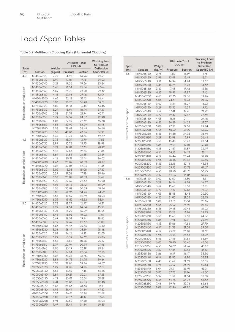
90 Cladding RailsKingspan Multibeam
Load / Span Tables
Span (m) Section
Weight (kg/m)
Ultimate Total UDL kN
Working Load to Produce Deflection
Span/150 kNPressure Suction5.5 M145065120 2.75 11.89 11.89 11.75 M145065130 2.99 13.49 13.49 12.71
M145065140 3.21 14.94 14.94 13.67M145065150 3.45 16.23 16.23 14.62M145065160 3.69 17.48 17.48 15.56M145065180 4.15 19.97 19.97 17.42M145065200 4.63 22.35 22.35 19.26M145065220 5.06 24.61 24.61 21.06M175065120 3.02 13.27 13.27 18.22M175065130 3.29 15.33 15.33 19.72M175065140 3.52 17.41 17.41 21.22M175065150 3.79 19.47 19.47 22.69M175065160 4.05 21.11 21.11 24.16M175065180 4.55 24.29 24.29 27.07M175065200 5.08 27.38 27.38 29.94M175065220 5.56 30.22 30.22 32.76M175065250 6.35 34.38 34.38 36.91M205065120 3.29 13.99 13.99 26.45M205065130 3.58 16.48 16.48 28.64M205065140 3.84 19.01 19.01 30.81M205065150 4.13 21.57 21.57 32.97M205065160 4.41 24.13 24.13 35.11M205065170 4.67 26.44 26.44 37.28M205065180 4.96 28.36 28.36 39.35M205065200 5.53 32.18 32.18 43.54M205065220 6.05 35.72 35.72 47.67M205065250 6.91 40.78 40.78 53.75M205065270 7.49 44.03 44.03 57.73
6.0 M175065120 3.02 12.50 12.50 15.31 M175065130 3.29 14.24 14.24 16.57
M175065140 3.52 15.68 15.68 17.83M175065150 3.79 17.10 17.10 19.07M175065160 4.05 18.48 18.48 20.30M175065180 4.55 21.03 21.03 22.75M175065200 5.08 23.51 23.51 25.16M175065220 5.56 25.92 25.92 27.53M175065250 6.35 29.45 29.45 31.02M205065120 3.29 13.28 13.28 22.23M205065130 3.58 15.60 15.60 24.06M205065140 3.84 17.91 17.91 25.89M205065150 4.13 19.66 19.66 27.70M205065160 4.41 21.38 21.38 29.50M205065170 4.67 23.02 23.02 31.32M205065180 4.96 24.53 24.53 33.07M205065200 5.53 27.53 27.53 36.59M205065220 6.05 30.45 30.45 40.06M205065250 6.91 34.69 34.69 45.17M205065270 7.49 37.43 37.43 48.51M235065130 3.86 16.17 16.17 33.30M235065140 4.14 18.90 18.90 35.83M235065150 4.45 21.69 21.69 38.35M235065160 4.76 23.92 23.92 40.84M235065170 5.04 25.91 25.91 43.31M235065180 5.35 27.76 27.76 45.80M235065200 5.97 31.34 31.34 50.69M235065220 6.53 34.78 34.78 55.52M235065250 7.46 39.76 39.76 62.64M235065270 8.08 42.96 42.96 67.30
Rest
rain
ts a
t m
id-s
pan
Rest
rain
ts a
t m
id-s
pan
Rest
rain
ts a
t m
id-s
pan
Rest
rain
ts a
t m
id-s
pan
Rest
rain
ts a
t m
id-s
pan
Table 3:9 Multibeam Cladding Rails (Horizontal Cladding)
Span (m) Section
Weight (kg/m)
Ultimate Total UDL kN
Working Load to Produce Deflection
Span/150 kNPressure Suction4.0 M145065120 2.75 14.96 14.96 22.21 M145065130 2.99 17.16 17.16 24.03
M145065140 3.21 19.36 19.36 25.84M145065150 3.45 21.54 21.54 27.64M145065160 3.69 23.70 23.70 29.42M145065180 4.15 27.96 27.96 32.94M145065200 4.63 32.12 32.12 36.41M145065220 5.06 36.20 36.20 39.81M175065120 3.02 16.18 16.18 34.45M175065130 3.29 18.94 18.94 37.29M175065140 3.52 21.74 21.74 40.11M175065150 3.79 24.57 24.57 42.90M175065160 4.05 27.39 27.39 45.68M175065180 4.55 32.99 32.99 51.18M175065200 5.08 38.49 38.49 56.60M175065220 5.56 43.86 43.86 61.93M175065250 6.35 51.73 51.73 69.79
4.5 M145065120 2.75 13.79 13.79 17.55 M145065130 2.99 15.75 15.75 18.99
M145065140 3.21 17.70 17.70 20.42M145065150 3.45 19.63 19.63 21.84M145065160 3.69 21.55 21.55 23.24M145065180 4.15 25.31 25.31 26.02M145065200 4.63 28.89 28.89 28.77M145065220 5.06 32.03 32.03 31.46M175065120 3.02 15.08 15.08 27.22M175065130 3.29 17.58 17.58 29.46M175065140 3.52 20.09 20.09 31.69M175065150 3.79 22.62 22.62 33.90M175065160 4.05 25.12 25.12 36.09M175065180 4.55 30.09 30.09 40.44M175065200 5.08 34.96 34.96 44.72M175065220 5.56 39.59 39.59 48.94M175065250 6.35 45.52 45.52 55.14
5.0 M145065120 2.75 12.77 12.77 14.21 M145065130 2.99 14.54 14.54 15.38
M145065140 3.21 16.29 16.29 16.54M145065150 3.45 18.02 18.02 17.69M145065160 3.69 19.74 19.74 18.83M145065180 4.15 22.67 22.67 21.08M145065200 4.63 25.46 25.46 23.30M145065220 5.06 28.19 28.19 25.48M175065120 3.02 14.12 14.12 22.05M175065130 3.29 16.39 16.39 23.86M175065140 3.52 18.66 18.66 25.67M175065150 3.79 20.94 20.94 27.46M175065160 4.05 23.19 23.19 29.24M175065180 4.55 27.64 27.64 32.76M175065200 5.08 31.26 31.26 36.23M175065220 5.56 34.75 34.75 39.64M175065250 6.35 39.86 39.86 44.67M205065120 3.29 14.76 14.76 32.01M205065130 3.58 17.45 17.45 34.65M205065140 3.84 20.21 20.21 37.28M205065150 4.13 23.01 23.01 39.89M205065160 4.41 25.83 25.83 42.48M205065170 4.67 28.66 28.66 45.11M205065180 4.96 31.44 31.44 47.62M205065200 5.53 36.81 36.81 52.69M205065220 6.05 41.17 41.17 57.68M205065250 6.91 47.50 47.50 65.04M205065270 7.49 51.44 51.44 69.85
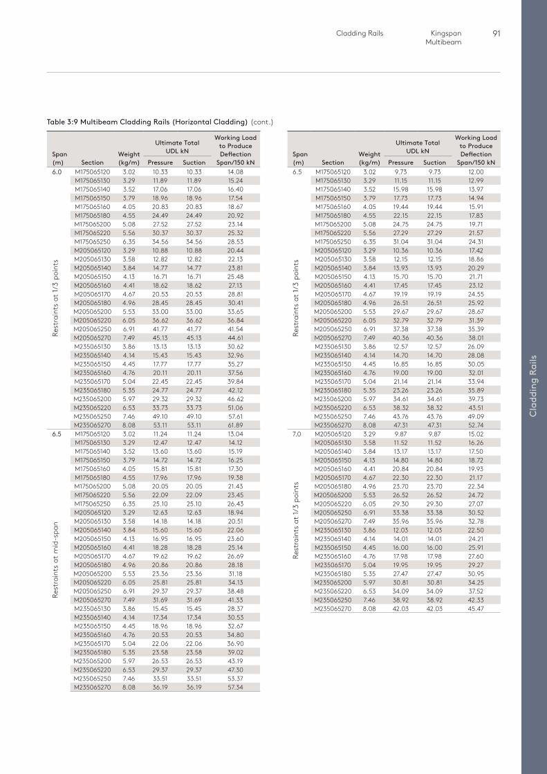
91 Cladding Rails Kingspan Multibeam
Cla
ddin
g Ra
ils
Span (m) Section
Weight (kg/m)
Ultimate Total UDL kN
Working Load to Produce Deflection
Span/150 kNPressure Suction6.5 M175065120 3.02 9.73 9.73 12.00 M175065130 3.29 11.15 11.15 12.99
M175065140 3.52 15.98 15.98 13.97M175065150 3.79 17.73 17.73 14.94M175065160 4.05 19.44 19.44 15.91M175065180 4.55 22.15 22.15 17.83M175065200 5.08 24.75 24.75 19.71M175065220 5.56 27.29 27.29 21.57M175065250 6.35 31.04 31.04 24.31M205065120 3.29 10.36 10.36 17.42M205065130 3.58 12.15 12.15 18.86M205065140 3.84 13.93 13.93 20.29M205065150 4.13 15.70 15.70 21.71M205065160 4.41 17.45 17.45 23.12M205065170 4.67 19.19 19.19 24.55M205065180 4.96 26.51 26.51 25.92M205065200 5.53 29.67 29.67 28.67M205065220 6.05 32.79 32.79 31.39M205065250 6.91 37.38 37.38 35.39M205065270 7.49 40.36 40.36 38.01M235065130 3.86 12.57 12.57 26.09M235065140 4.14 14.70 14.70 28.08M235065150 4.45 16.85 16.85 30.05M235065160 4.76 19.00 19.00 32.01M235065170 5.04 21.14 21.14 33.94M235065180 5.35 23.26 23.26 35.89M235065200 5.97 34.61 34.61 39.73M235065220 6.53 38.32 38.32 43.51M235065250 7.46 43.76 43.76 49.09M235065270 8.08 47.31 47.31 52.74
7.0 M205065120 3.29 9.87 9.87 15.02 M205065130 3.58 11.52 11.52 16.26
M205065140 3.84 13.17 13.17 17.50M205065150 4.13 14.80 14.80 18.72M205065160 4.41 20.84 20.84 19.93M205065170 4.67 22.30 22.30 21.17M205065180 4.96 23.70 23.70 22.34M205065200 5.53 26.52 26.52 24.72M205065220 6.05 29.30 29.30 27.07M205065250 6.91 33.38 33.38 30.52M205065270 7.49 35.96 35.96 32.78M235065130 3.86 12.03 12.03 22.50M235065140 4.14 14.01 14.01 24.21M235065150 4.45 16.00 16.00 25.91M235065160 4.76 17.98 17.98 27.60M235065170 5.04 19.95 19.95 29.27M235065180 5.35 27.47 27.47 30.95M235065200 5.97 30.81 30.81 34.25M235065220 6.53 34.09 34.09 37.52M235065250 7.46 38.92 38.92 42.33M235065270 8.08 42.03 42.03 45.47
Span (m) Section
Weight (kg/m)
Ultimate Total UDL kN
Working Load to Produce Deflection
Span/150 kNPressure Suction6.0 M175065120 3.02 10.33 10.33 14.08 M175065130 3.29 11.89 11.89 15.24
M175065140 3.52 17.06 17.06 16.40M175065150 3.79 18.96 18.96 17.54M175065160 4.05 20.83 20.83 18.67M175065180 4.55 24.49 24.49 20.92M175065200 5.08 27.52 27.52 23.14M175065220 5.56 30.37 30.37 25.32M175065250 6.35 34.56 34.56 28.53M205065120 3.29 10.88 10.88 20.44M205065130 3.58 12.82 12.82 22.13M205065140 3.84 14.77 14.77 23.81M205065150 4.13 16.71 16.71 25.48M205065160 4.41 18.62 18.62 27.13M205065170 4.67 20.53 20.53 28.81M205065180 4.96 28.45 28.45 30.41M205065200 5.53 33.00 33.00 33.65M205065220 6.05 36.62 36.62 36.84M205065250 6.91 41.77 41.77 41.54M205065270 7.49 45.13 45.13 44.61M235065130 3.86 13.13 13.13 30.62M235065140 4.14 15.43 15.43 32.96M235065150 4.45 17.77 17.77 35.27M235065160 4.76 20.11 20.11 37.56M235065170 5.04 22.45 22.45 39.84M235065180 5.35 24.77 24.77 42.12M235065200 5.97 29.32 29.32 46.62M235065220 6.53 33.73 33.73 51.06M235065250 7.46 49.10 49.10 57.61M235065270 8.08 53.11 53.11 61.89
6.5 M175065120 3.02 11.24 11.24 13.04 M175065130 3.29 12.47 12.47 14.12
M175065140 3.52 13.60 13.60 15.19M175065150 3.79 14.72 14.72 16.25M175065160 4.05 15.81 15.81 17.30M175065180 4.55 17.96 17.96 19.38M175065200 5.08 20.05 20.05 21.43M175065220 5.56 22.09 22.09 23.45M175065250 6.35 25.10 25.10 26.43M205065120 3.29 12.63 12.63 18.94M205065130 3.58 14.18 14.18 20.51M205065140 3.84 15.60 15.60 22.06M205065150 4.13 16.95 16.95 23.60M205065160 4.41 18.28 18.28 25.14M205065170 4.67 19.62 19.62 26.69M205065180 4.96 20.86 20.86 28.18M205065200 5.53 23.36 23.36 31.18M205065220 6.05 25.81 25.81 34.13M205065250 6.91 29.37 29.37 38.48M205065270 7.49 31.69 31.69 41.33M235065130 3.86 15.45 15.45 28.37M235065140 4.14 17.34 17.34 30.53M235065150 4.45 18.96 18.96 32.67M235065160 4.76 20.53 20.53 34.80M235065170 5.04 22.06 22.06 36.90M235065180 5.35 23.58 23.58 39.02M235065200 5.97 26.53 26.53 43.19M235065220 6.53 29.37 29.37 47.30M235065250 7.46 33.51 33.51 53.37M235065270 8.08 36.19 36.19 57.34
Table 3:9 Multibeam Cladding Rails (Horizontal Cladding) (cont.)
Rest
rain
ts a
t 1/3
poi
nts
Rest
rain
ts a
t 1/3
poi
nts
Rest
rain
ts a
t m
id-s
pan
Rest
rain
ts a
t 1/3
poi
nts
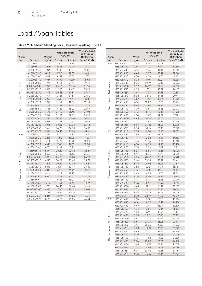
92 Cladding RailsKingspan Multibeam
Load / Span Tables
Span (m) Section
Weight (kg/m)
Ultimate Total UDL kN
Working Load to Produce Deflection
Span/150 kNPressure Suction8.0 M235065120 3.55 8.39 8.39 13.67 M235065130 3.86 9.90 9.90 14.80
M235065140 4.14 11.44 11.44 15.92M235065150 4.45 12.97 12.97 17.04M235065160 4.76 14.50 14.50 18.15M235065170 5.04 16.01 16.01 19.25M235065180 5.35 22.19 22.19 20.35M235065200 5.97 24.97 24.97 22.53M235065220 6.53 27.72 27.72 24.67M235065250 7.46 31.73 31.73 27.83M235065270 8.08 34.16 34.16 29.91M265065120 3.82 8.39 8.39 18.22M265065130 4.16 10.09 10.09 19.73M265065140 4.46 11.85 11.85 21.24M265065150 4.79 13.65 13.65 22.73M265065160 5.13 15.45 15.45 24.22M265065180 5.76 19.07 19.07 27.17M265065200 6.43 28.33 28.33 30.08M265065220 7.03 31.53 31.53 32.95M265065250 8.03 36.22 36.22 37.20M265065270 8.70 39.13 39.13 39.98
9.0 M235065120 3.55 10.70 10.70 12.57 M235065130 3.86 11.79 11.79 13.61
M235065140 4.14 12.88 12.88 14.65M235065150 4.45 13.96 13.96 15.68M235065160 4.76 14.93 14.93 16.70M235065170 5.04 15.89 15.89 17.71M235065180 5.35 16.86 16.86 18.72M235065200 5.97 18.75 18.75 20.72M235065220 6.53 20.58 20.58 22.70M235065250 7.46 23.28 23.28 25.61M235065270 8.08 25.04 25.04 27.51M265065120 3.82 8.78 8.78 16.76M265065130 4.16 13.10 13.10 18.15M265065140 4.46 14.35 14.35 19.54M265065150 4.79 15.59 15.59 20.91M265065160 5.13 16.78 16.78 22.28M265065180 5.76 18.97 18.97 24.99M265065200 6.43 21.11 21.11 27.67M265065220 7.03 23.20 23.20 30.31M265065250 8.03 26.25 26.25 34.22M265065270 8.70 28.22 28.22 36.77
9.0 M235065130 3.86 9.52 9.52 13.20M235065140 4.14 10.97 10.97 14.20M235065150 4.45 12.41 12.41 15.20M235065160 4.76 13.84 13.84 16.19M235065170 5.04 18.91 18.91 17.17M235065180 5.35 20.21 20.21 18.15M235065200 5.97 22.74 22.74 20.09M235065220 6.53 25.25 25.25 22.01M235065250 7.46 28.63 28.63 24.83M235065270 8.08 30.81 30.81 26.68M265065140 4.46 11.43 11.43 18.95M265065150 4.79 13.12 13.12 20.28M265065160 5.13 14.82 14.82 21.60M265065180 5.76 22.80 22.80 24.23M265065200 6.43 25.74 25.74 26.83M265065220 7.03 28.64 28.64 29.39M265065250 8.03 32.66 32.66 33.18M265065270 8.70 35.16 35.16 35.66
Span (m) Section
Weight (kg/m)
Ultimate Total UDL kN
Working Load to Produce Deflection
Span/150 kNPressure Suction7.5 M205065120 3.29 9.42 9.42 13.08 M205065130 3.58 10.95 10.95 14.17
M205065140 3.84 12.47 12.47 15.24M205065150 4.13 17.30 17.30 16.31M205065160 4.41 18.59 18.59 17.37M205065170 4.67 19.90 19.90 18.44M205065180 4.96 21.14 21.14 19.47M205065200 5.53 23.66 23.66 21.54M205065220 6.05 26.13 26.13 23.58M205065250 6.91 29.58 29.58 26.59M205065270 7.49 31.81 31.81 28.55M235065120 3.55 9.72 9.72 18.10M235065130 3.86 11.53 11.53 19.60M235065140 4.14 13.37 13.37 21.09M235065150 4.45 15.22 15.22 22.57M235065160 4.76 21.40 21.40 24.04M235065170 5.04 22.89 22.89 25.50M235065180 5.35 24.40 24.40 26.96M235065200 5.97 27.37 27.37 29.84M235065220 6.53 30.28 30.28 32.68M235065250 7.46 34.38 34.38 36.87M235065270 8.08 36.98 36.98 39.61
8.0 M235065120 3.55 9.35 9.35 15.91 M235065130 3.86 11.06 11.06 17.23
M235065140 4.14 12.78 12.78 18.54M235065150 4.45 17.65 17.65 19.84M235065160 4.76 18.99 18.99 21.13M235065170 5.04 20.32 20.32 22.41M235065180 5.35 21.66 21.66 23.69M235065200 5.97 24.28 24.28 26.23M235065220 6.53 26.69 26.69 28.72M235065250 7.46 30.20 30.20 32.41M235065270 8.08 32.47 32.47 34.82M265065120 3.82 9.34 9.34 21.21M265065130 4.16 11.25 11.25 22.98M265065140 4.46 13.22 13.22 24.73M265065150 4.79 15.23 15.23 26.47M265065160 5.13 21.34 21.34 28.19M265065180 5.76 24.40 24.40 31.63M265065200 6.43 27.43 27.43 35.02M265065220 7.03 30.25 30.25 38.36M265065250 8.03 34.26 34.26 43.30M265065270 8.70 36.86 36.86 46.54
Rest
rain
ts a
t 1/3
poi
nts
Rest
rain
ts a
t 1/3
poi
nts
Rest
rain
ts a
t 1/4
poi
nts
Rest
rain
ts a
t 1/3
poi
nts
Rest
rain
ts a
t 1/4
poi
nts
Table 3:9 Multibeam Cladding Rails (Horizontal Cladding) (cont.)
Cla
ddin
g Ra
ils
93 Cladding Rails Kingspan Multibeam
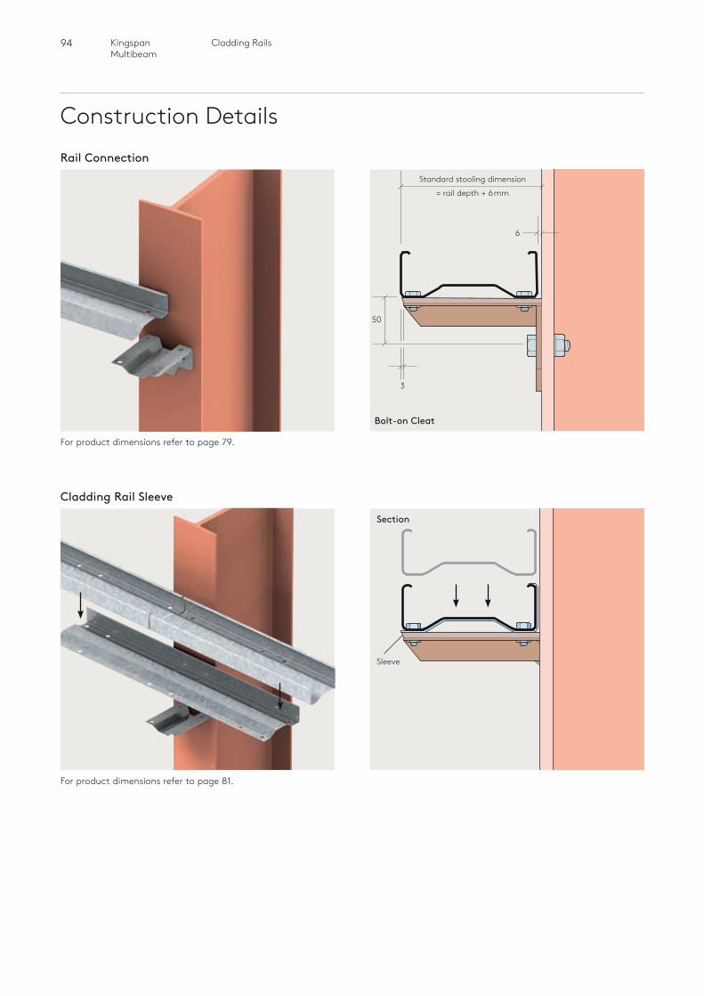
94 Cladding RailsKingspan Multibeam
Construction DetailsRail Connection
For product dimensions refer to page 79.
Cladding Rail Sleeve
Bolt-on Cleat
6
50
3
Standard stooling dimension
= rail depth + 6mm
Section
Sleeve
For product dimensions refer to page 81.
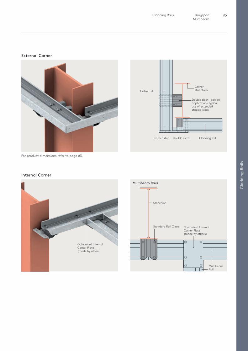
95 Cladding Rails Kingspan Multibeam
Cla
ddin
g Ra
ilsGalvanised Internal Corner Plate (made by others)
External Corner
For product dimensions refer to page 83.
Internal Corner
Gable rail
Corner stub
Double cleat (bolt on application) Typical use of extended stooled cleat
Corner stanchion
Double cleat Cladding rail
Multibeam Rails
Galvanised Internal Corner Plate (made by others)
Stanchion
Standard Rail Cleat
Multibeam Rail
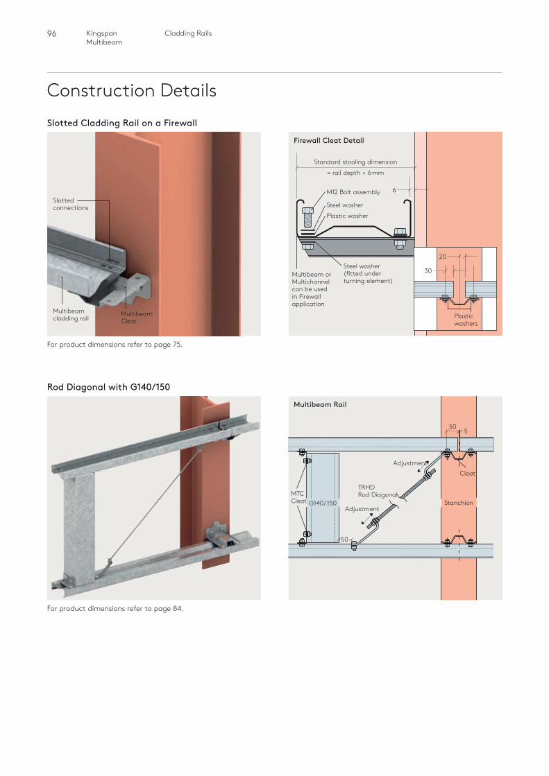
96 Cladding RailsKingspan Multibeam
Construction Details
Multibeam Cleat
Slotted connections
Multibeam cladding rail
For product dimensions refer to page 75.
Firewall Cleat Detail
6
Standard stooling dimension
= rail depth + 6mm
Multibeam or Multichannel can be used in Firewall application
20
30
Plastic washers
Rod Diagonal with G140/150
For product dimensions refer to page 84.
MTCCleat
TRHDRod Diagonal
Adjustment
Adjustment
StanchionG140/150
Multibeam Rail
50
Cleat
550
Slotted Cladding Rail on a Firewall
Plastic washerSteel washer
Steel washer (fitted under turning element)
M12 Bolt assembly
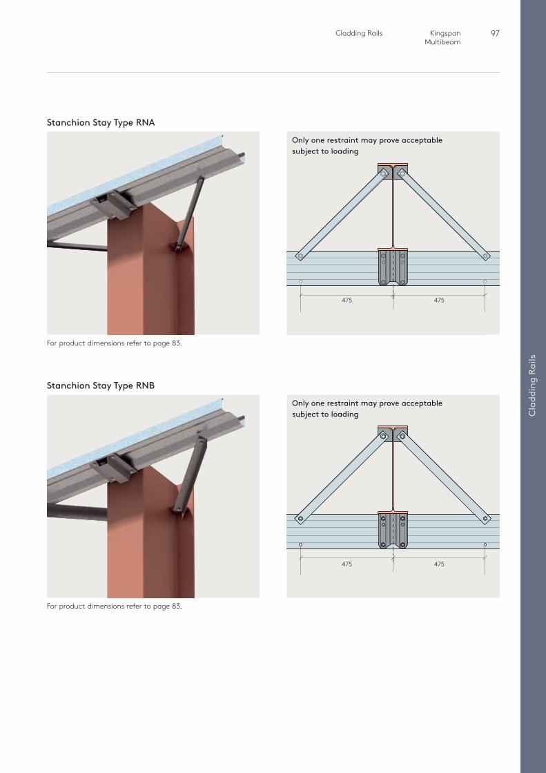
97 Cladding Rails Kingspan Multibeam
Cla
ddin
g Ra
ils
For product dimensions refer to page 83.
Stanchion Stay Type RNA
For product dimensions refer to page 83.
Stanchion Stay Type RNB
Only one restraint may prove acceptable subject to loading
Only one restraint may prove acceptable subject to loading
475 475
475 475
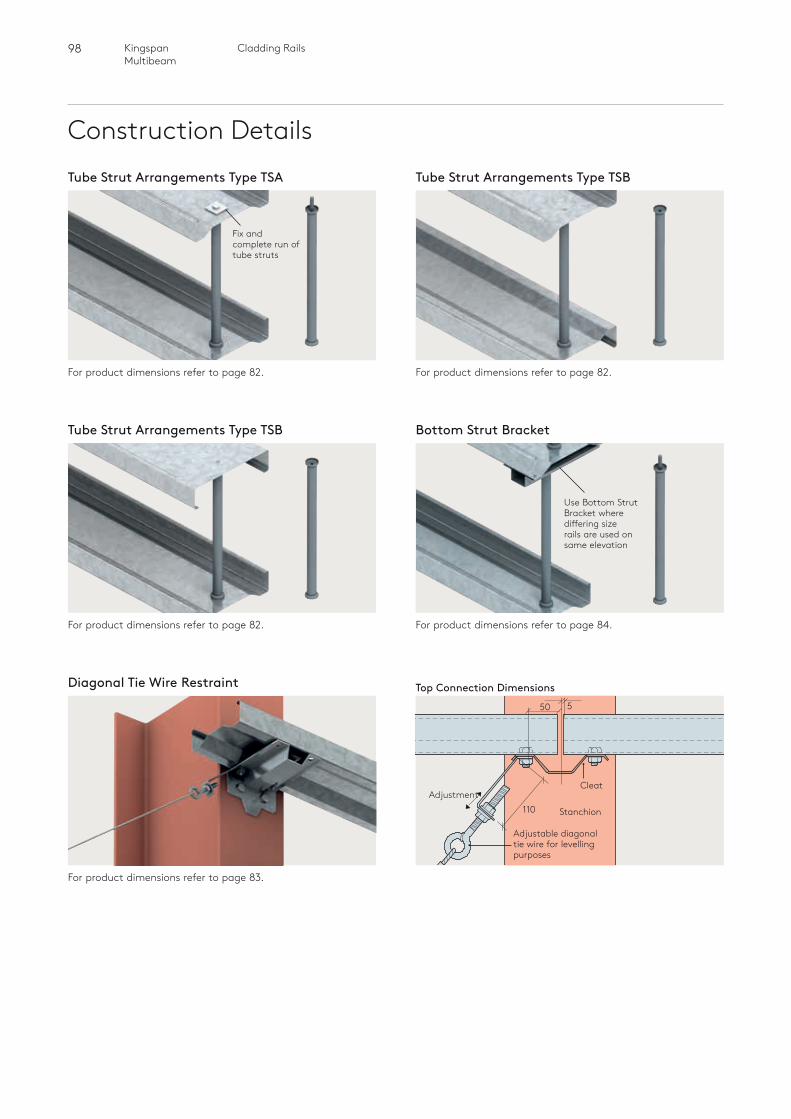
98 Cladding RailsKingspan Multibeam
Construction Details
For product dimensions refer to page 83.
For product dimensions refer to page 82. For product dimensions refer to page 84.
For product dimensions refer to page 82. For product dimensions refer to page 82.
Tube Strut Arrangements Type TSA Tube Strut Arrangements Type TSB
Fix and complete run of tube struts
Tube Strut Arrangements Type TSB Bottom Strut Bracket
Diagonal Tie Wire Restraint
Use Bottom Strut Bracket where differing size rails are used on same elevation
Top Connection Dimensions550
110Adjustment
Stanchion
Cleat
Adjustable diagonal tie wire for levelling purposes
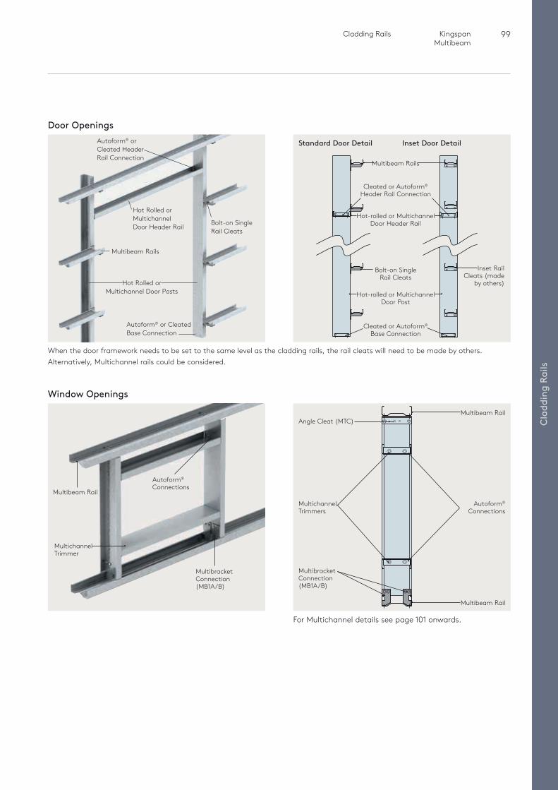
99 Cladding Rails Kingspan Multibeam
Cla
ddin
g Ra
ils
Door Openings
When the door framework needs to be set to the same level as the cladding rails, the rail cleats will need to be made by others. Alternatively, Multichannel rails could be considered.
Autoform® or Cleated Header Rail Connection
Bolt-on Single Rail Cleats
Hot Rolled or Multichannel Door Header Rail
Hot Rolled or Multichannel Door Posts
Multibeam Rails
Autoform® or Cleated Base Connection
Multibeam Rail
Multichannel Trimmer
Window Openings
For Multichannel details see page 101 onwards.
Multibeam Rails
Hot-rolled or Multichannel Door Post
Bolt-on Single Rail Cleats
Inset Rail Cleats (made
by others)
Cleated or Autoform® Base Connection
Multibeam Rail
Autoform® Connections
Multibeam Rail
Cleated or Autoform® Header Rail Connection
Hot-rolled or Multichannel Door Header Rail
Standard Door Detail
Multichannel Trimmers
Multibracket Connection (MB1A/B)
Autoform® Connections
Inset Door Detail
Angle Cleat (MTC)
Multibracket Connection (MB1A/B)

Multichannel
100 MultichannelKingspan Multibeam
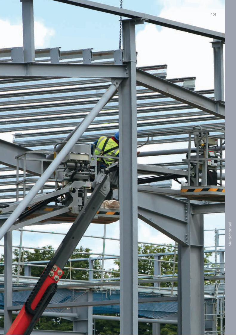
101
Mul
tich
anne
l
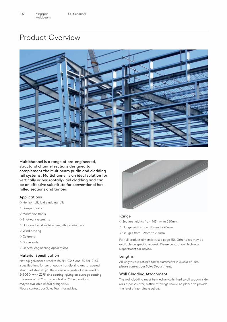
102 MultichannelKingspan Multibeam
Product Overview
Multichannel is a range of pre-engineered, structural channel sections designed to complement the Multibeam purlin and cladding rail systems. Multichannel is an ideal solution for vertically or horizontally-laid cladding and can be an effective substitute for conventional hot-rolled sections and timber.
ApplicationsHorizontally laid cladding rails
Parapet posts
Mezzanine floors
Brickwork restraints
Door and window trimmers, ribbon windows
Wind bracing
Columns
Gable ends
General engineering applications
Material SpecificationHot dip galvanised steel to BS EN 10346 and BS EN 10143 ‘specifications for continuously hot dip zinc /metal coated structural steel strip’. The minimum grade of steel used is S450GD, with Z275 zinc coating, giving an average coating thickness of 0.02mm to each side. Other coatings maybe available (G600 / Magnelis). Please contact our Sales Team for advice.
RangeSection heights from 145mm to 350mm
Flange widths from 70mm to 90mm
Gauges from 1.2mm to 2.7mm
For full product dimensions see page 110. Other sizes may be available on specific request. Please contact our Technical Department for advice.
LengthsAll lengths are catered for; requirements in excess of 18m, please contact our Sales Department.
Wall Cladding AttachmentThe wall cladding must be mechanically fixed to all support side rails it passes over, sufficient fixings should be placed to provide the level of restraint required.
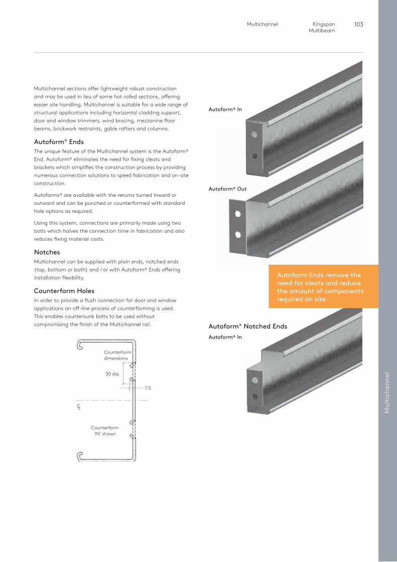
103 Multichannel Kingspan Multibeam
Autoform Ends remove the need for cleats and reduce the amount of componentsrequired on site.
Mul
tich
anne
l
Multichannel sections offer lightweight robust construction and may be used in lieu of some hot rolled sections, offering easier site handling. Multichannel is suitable for a wide range of structural applications including horizontal cladding support, door and window trimmers, wind bracing, mezzanine floor beams, brickwork restraints, gable rafters and columns.
Autoform® EndsThe unique feature of the Multichannel system is the Autoform® End. Autoform® eliminates the need for fixing cleats and brackets which simplifies the construction process by providing numerous connection solutions to speed fabrication and on-site construction.
Autoforms® are available with the returns turned inward or outward and can be punched or counterformed with standard hole options as required.
Using this system, connections are primarily made using two bolts which halves the connection time in fabrication and also reduces fixing material costs.
NotchesMultichannel can be supplied with plain ends, notched ends (top, bottom or both) and / or with Autoform® Ends offering installation flexibility.
Counterform HolesIn order to provide a flush connection for door and window applications an off-line process of counterforming is used. This enables countersunk bolts to be used without compromising the finish of the Multichannel rail.
Autoform® In
Autoform® In
Autoform® Notched Ends
Autoform® Out
Counterform‘IN’ shown
30 dia.
7.5
C L
Counterform dimensions
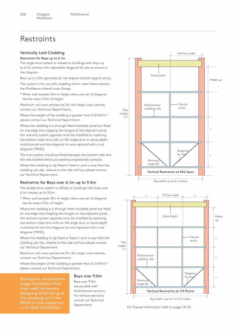
104 MultichannelKingspan Multibeam
Restraints
=1/3 bay width=
Vertically Laid CladdingRestraints for Bays up to 6.1mThe single strut system is utilised on buildings with bays up to 6.1m centres with adjustable diagonal tie wire as shown in the diagram.
Bays up to 3.0m generally do not require vertical support struts.
This system is for use with cladding which, when fixed restrains the Multibeam siderail outer flange.
* When wall exceeds 10m in height allow one set of diagonal ties for every 9.0m of height.
Maximum rail cross centres are 2m (for larger cross centres, contact our Technical Department).
Where the weight of the cladding is greater than 0.12 kN/m2
please contact our Technical Department.
Where the cladding is a through-fixed insulated panel but fixed on one edge only trapping the tongue of the adjacent panel, the restraint system opposite must be modified by replacing the bottom tube strut with an SW angle strut or same depth multichannel and the diagonal tie wire replaced with a rod diagonal (TRHD).
The strut system should be fitted between the bottom rails and the rails levelled before proceeding progressively upwards.
Where the cladding is clip fixed or fixed in such a way that the cladding can slip, relative to the side rail face please contact our Technical Department.
Restraints for Bays over 6.1m up to 9.0mThe double strut system is utilised on buildings with bays over 6.1m metres up to 9.0m.
* When wall exceeds 10m in height allow one set of diagonal ties for every 9.0m of height.
Where the cladding is a through-fixed insulated panel but fixed on one edge only trapping the tongue on the adjacent panel, the restraint system opposite must be modified by replacing the bottom tube strut with an SW angle strut or same depth multichannel and the diagonal tie wire replaced with a rod diagonal (TRHD).
Where the cladding is clip fixed or fixed in such a way that the cladding can slip, relative to the side rail face please contact our Technical Department.
Maximum rail cross centres are 2m (for larger cross centres, contact our Technical Department).
Where the weight of the cladding is greater than 0.12 kN/m2
please contact our Technical Department.
Bays over 9.0mBays over 9.0m are possible with Multichannel sections. For vertical restraints consult our Technical Department.
=
=
Half bay width
Maker up
Bay width over 6.1 to 9.0 metres
Tubularstruts
Tubularstruts
Eaves beam
Eaves beam
Multichannelcladding rails
Multichannelcladding rails
Diagonal tie wire
Diagonal tie wire
=
Makerup
=
=Minimumangle 30˚
Minimumangle 30˚
Bay width up to 6.1 metres
Vertical Restraints at Mid Span
Vertical Restraints at 1/3 Points
For Firewall information refer to pages 74-76.
Maxheight
‘x’*
Maxheight
‘x’*
During the construction stage the bottom Rail may need temporary propping while fixing of the cladding until the Panel is fully supported in its final installation.
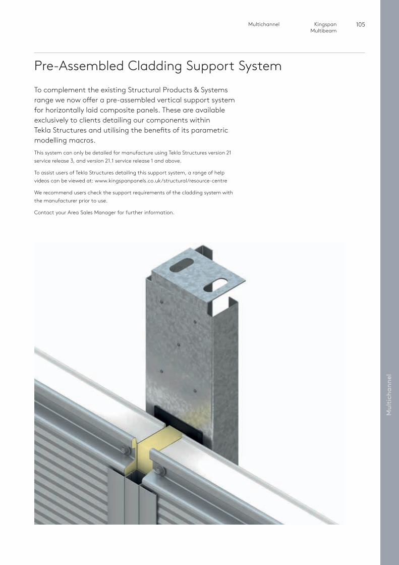
105 Multichannel Kingspan Multibeam
Mul
tich
anne
l
Pre-Assembled Cladding Support SystemTo complement the existing Structural Products & Systems range we now offer a pre-assembled vertical support system for horizontally laid composite panels. These are available exclusively to clients detailing our components within Tekla Structures and utilising the benefits of its parametric modelling macros.This system can only be detailed for manufacture using Tekla Structures version 21 service release 3, and version 21.1 service release 1 and above.
To assist users of Tekla Structures detailing this support system, a range of help videos can be viewed at: www.kingspanpanels.co.uk/structural/resource-centre
We recommend users check the support requirements of the cladding system with the manufacturer prior to use.
Contact your Area Sales Manager for further information.
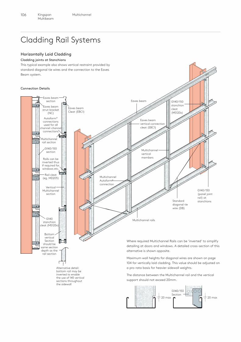
106 MultichannelKingspan Multibeam
Cladding Rail Systems
Multichannel rails
Eaves beam
Standard diagonal tie wire (DB)
G140/150 stanchion cleat (MS120x)
Multichannel Autoform® connection
G140/150(panel joint rail) at stanchions
Alternative detail: bottom rail may be inverted to enable the use of 145 vertical sections throughout the sidewall
Horizontally Laid CladdingCladding joints at StanchionsThis typical example also shows vertical restraint provided by standard diagonal tie wires and the connection to the Eaves Beam system.
Connection Details
Eaves beam section
Eaves beam strut bracket
(NC)
Autoform® connections used for all
channel-channel connections
G140 stanchion
cleat (MS120x)
Eaves beam Cleat (EBC1)
Vertical Multichannel
section
G140/150 section
Rails can be inverted thus if required for windows etc.
Rail cleat (eg. MD205)
Multichannel rail section
Bottom vertical Section
should be same section depth as the rail section
Where required Multichannel Rails can be ‘inverted’ to simplify detailing at doors and windows. A detailed cross-section of this alternative is shown opposite.
Maximum wall heights for diagonal wires are shown on page 104 for vertically laid cladding. This value should be adjusted on a pro-rata basis for heavier sidewall weights.
The distance between the Multichannel rail and the vertical support should not exceed 20mm.
20 max 20 max
G140/150 Section
Eaves beam vertical connection cleat (EBC1)
Multichannel vertical members
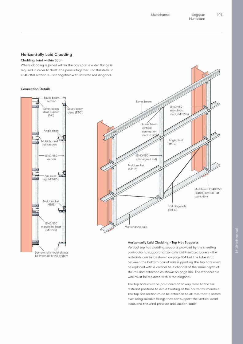
107 Multichannel Kingspan Multibeam
Mul
tich
anne
l
Horizontally Laid CladdingCladding Joint within SpanWhere cladding is joined within the bay span a wider flange is required in order to ‘butt’ the panels together. For this detail a G140/150 section is used together with screwed rod diagonal.
Horizontally Laid Cladding – Top Hat SupportsVertical top hat cladding supports provided by the sheeting contractor to support horizontally laid insulated panels – the restraints can be as shown on page 104 but the tube strut between the bottom pair of rails supporting the top hats must be replaced with a vertical Multichannel of the same depth of the rail and attached as shown on page 106. The standard tie wire must be replaced with a rod diagonal.
The top hats must be positioned at or very close to the rail restraint positions to avoid twisting of the horizontal member. The top hat section must be attached to all rails that it passes over using suitable fixings that can support the vertical dead loads and the wind pressure and suction loads.
Eaves beam
Multichannel rails
Rod diagonals (TRHD)
Angle cleat (MTC)
Eaves beam vertical connection cleat (EBC1)
G140/150(panel joint rail)
G140/150 stanchion cleat (MS120x)
Multibracket (MB1B)
Multibeam G140/150(panel joint rail) at stanchions
Connection Details
Eaves beam section
Eaves beam strut bracket
(NC)
Angle cleat
Multibracket (MB1B)
G140/150 stanchion cleat
(MS120x)
Eaves beam cleat (EBC1)
G140/150 section
Rail cleat (eg. MD205)
Multichannel rail section
Bottom rail should always be inverted in this system
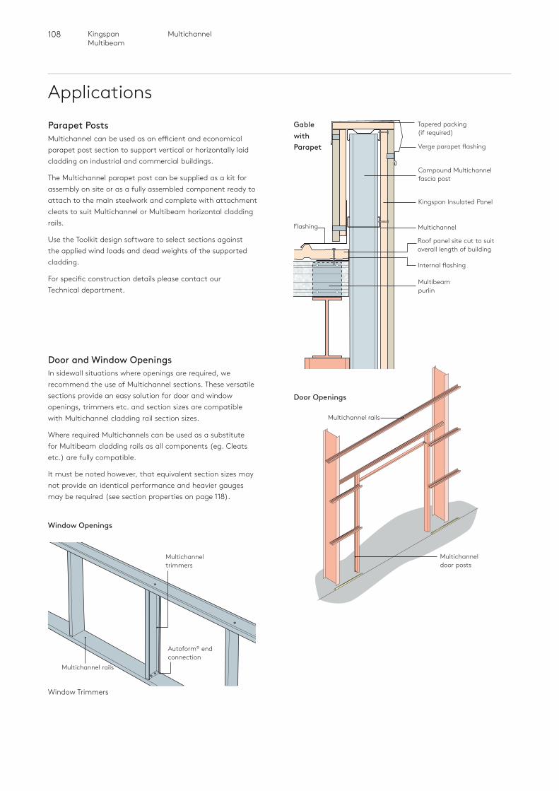
108 MultichannelKingspan Multibeam
Applications
Door and Window OpeningsIn sidewall situations where openings are required, we recommend the use of Multichannel sections. These versatile sections provide an easy solution for door and window openings, trimmers etc. and section sizes are compatible with Multichannel cladding rail section sizes.
Where required Multichannels can be used as a substitute for Multibeam cladding rails as all components (eg. Cleats etc.) are fully compatible.
It must be noted however, that equivalent section sizes may not provide an identical performance and heavier gauges may be required (see section properties on page 118).
Multichannel rails
Multichannel door posts
Window Openings
Window Trimmers
Multichannel trimmers
Autoform® end connection
Multichannel rails
Parapet PostsMultichannel can be used as an efficient and economical parapet post section to support vertical or horizontally laid cladding on industrial and commercial buildings.
The Multichannel parapet post can be supplied as a kit for assembly on site or as a fully assembled component ready to attach to the main steelwork and complete with attachment cleats to suit Multichannel or Multibeam horizontal cladding rails.
Use the Toolkit design software to select sections against the applied wind loads and dead weights of the supported cladding.
For specific construction details please contact our Technical department.
Tapered packing(if required)
Gable with Parapet
Kingspan Insulated Panel
Compound Multichannel fascia post
Multichannel
Roof panel site cut to suit overall length of building
Internal flashing
Multibeam purlin
Flashing
Verge parapet flashing
Door Openings
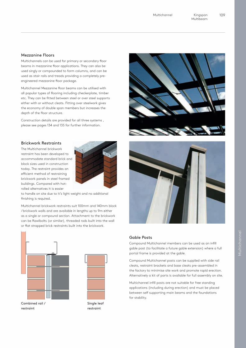
109 Multichannel Kingspan Multibeam
Mul
tich
anne
l
Combined rail / restraint
Single leaf restraint
Brickwork RestraintsThe Multichannel brickwork restraint has been developed to accommodate standard brick and block sizes used in construction today. The restraint provides an efficient method of restraining brickwork panels in steel framed buildings. Compared with hot-rolled alternatives it is easier to handle on site due to it’s light weight and no additional finishing is required.
Multichannel brickwork restraints suit 100mm and 140mm block / brickwork walls and are available in lengths up to 9m either as a single or compound section. Attachment to the brickwork can be Rawlbolts (or similar), threaded rods built into the wall or flat strapped brick restraints built into the brickwork.
Gable PostsCompound Multichannel members can be used as an infill gable post (to facilitate a future gable extension) where a full portal frame is provided at the gable.
Compound Multichannel posts can be supplied with side rail cleats, restraint brackets and base cleats pre-assembled in the factory to minimise site work and promote rapid erection. Alternatively a kit of parts is available for full assembly on site.
Multichannel infill posts are not suitable for free standing applications (including during erection) and must be placed between self supporting main beams and the foundations for stability.
Mezzanine FloorsMultichannels can be used for primary or secondary floor beams in mezzanine floor applications. They can also be used singly or compounded to form columns, and can be used as stair rails and treads providing a completely pre-engineered mezzanine floor package.
Multichannel Mezzanine floor beams can be utilised with all popular types of flooring including checkerplate, timber etc. They can be fitted between steel or over steel supports either with or without cleats. Fitting over steelwork gives the economy of double span members but increases the depth of the floor structure.
Construction details are provided for all three systems , please see pages 134 and 135 for further information.
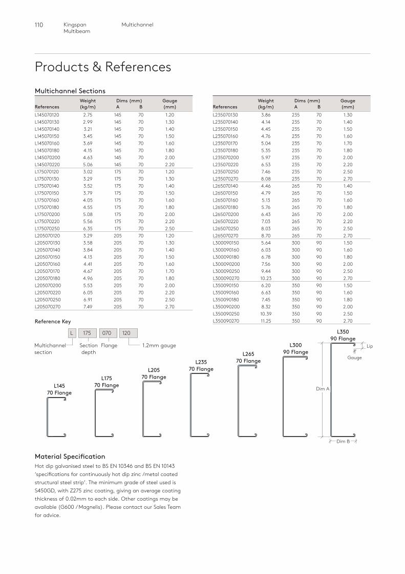
110 MultichannelKingspan Multibeam
Products & ReferencesMultichannel Sections
Lip
Dim B
Dim A
L35090 Flange
L30090 FlangeL265
70 FlangeL23570 FlangeL205
70 FlangeL17570 FlangeL145
70 Flange
Section depth
FlangeMultichannel section
1.2mm gauge
L 175 070 120
Reference Key
Weight Dims (mm) GaugeReferences (kg/m) A B (mm)L145070120 2.75 145 70 1.20L145070130 2.99 145 70 1.30L145070140 3.21 145 70 1.40L145070150 3.45 145 70 1.50L145070160 3.69 145 70 1.60L145070180 4.15 145 70 1.80L145070200 4.63 145 70 2.00L145070220 5.06 145 70 2.20L175070120 3.02 175 70 1.20L175070130 3.29 175 70 1.30L175070140 3.52 175 70 1.40L175070150 3.79 175 70 1.50L175070160 4.05 175 70 1.60L175070180 4.55 175 70 1.80L175070200 5.08 175 70 2.00L175070220 5.56 175 70 2.20L175070250 6.35 175 70 2.50L205070120 3.29 205 70 1.20L205070130 3.58 205 70 1.30L205070140 3.84 205 70 1.40L205070150 4.13 205 70 1.50L205070160 4.41 205 70 1.60L205070170 4.67 205 70 1.70L205070180 4.96 205 70 1.80L205070200 5.53 205 70 2.00L205070220 6.05 205 70 2.20L205070250 6.91 205 70 2.50L205070270 7.49 205 70 2.70
Weight Dims (mm) GaugeReferences (kg/m) A B (mm)L235070130 3.86 235 70 1.30L235070140 4.14 235 70 1.40L235070150 4.45 235 70 1.50L235070160 4.76 235 70 1.60L235070170 5.04 235 70 1.70L235070180 5.35 235 70 1.80L235070200 5.97 235 70 2.00L235070220 6.53 235 70 2.20L235070250 7.46 235 70 2.50L235070270 8.08 235 70 2.70L265070140 4.46 265 70 1.40L265070150 4.79 265 70 1.50L265070160 5.13 265 70 1.60L265070180 5.76 265 70 1.80L265070200 6.43 265 70 2.00L265070220 7.03 265 70 2.20L265070250 8.03 265 70 2.50L265070270 8.70 265 70 2.70L300090150 5.64 300 90 1.50L300090160 6.03 300 90 1.60L300090180 6.78 300 90 1.80L300090200 7.56 300 90 2.00L300090250 9.44 300 90 2.50L300090270 10.23 300 90 2.70L350090150 6.20 350 90 1.50L350090160 6.63 350 90 1.60L350090180 7.45 350 90 1.80L350090200 8.32 350 90 2.00L350090250 10.39 350 90 2.50L350090270 11.25 350 90 2.70
Gauge
Material SpecificationHot dip galvanised steel to BS EN 10346 and BS EN 10143 ‘specifications for continuously hot dip zinc /metal coated structural steel strip’. The minimum grade of steel used is S450GD, with Z275 zinc coating, giving an average coating thickness of 0.02mm to each side. Other coatings may be available (G600 / Magnelis). Please contact our Sales Team for advice.
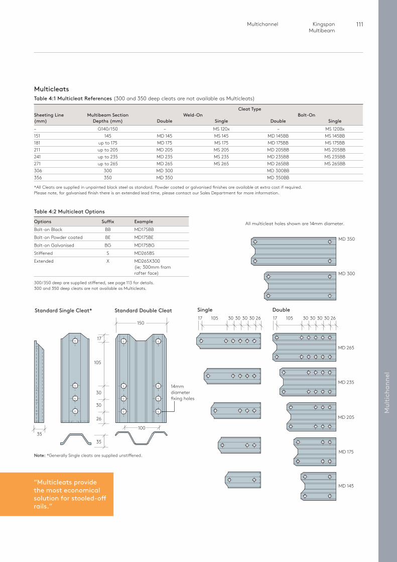
111 Multichannel Kingspan Multibeam
Mul
tich
anne
l
MD 350
MD 300
MD 265
3017 105 30 30 30 26
MD 235
MD 205
MD 175
MD 145
Cleat TypeSheeting Line Multibeam Section Weld-On Bolt-On(mm) Depths (mm) Double Single Double Single– G140/150 – MS 120x – MS 120Bx 151 145 MD 145 MS 145 MD 145BB MS 145BB 181 up to 175 MD 175 MS 175 MD 175BB MS 175BB 211 up to 205 MD 205 MS 205 MD 205BB MS 205BB 241 up to 235 MD 235 MS 235 MD 235BB MS 235BB271 up to 265 MD 265 MS 265 MD 265BB MS 265BB306 300 MD 300 MD 300BB 356 350 MD 350 MD 350BB
*All Cleats are supplied in unpainted black steel as standard. Powder coated or galvanised finishes are available at extra cost if required. Please note, for galvanised finish there is an extended lead time, please contact our Sales Department for more information.
3017 105 30 30 30 26
MulticleatsTable 4:1 Multicleat References (300 and 350 deep cleats are not available as Multicleats)
All multicleat holes shown are 14mm diameter.
Double Single
14mm diameter fixing holes
Standard Double CleatStandard Single Cleat*
26
35
30
30
17
105
150
35
Table 4:2 Multicleat Options
Options Suffix ExampleBolt-on Black BB MD175BB
Bolt-on Powder coated BE MD175BE
Bolt-on Galvanised BG MD175BG
Stiffened S MD265BS
Extended X MD265X300 (ie; 300mm from
rafter face)
300/350 deep are supplied stiffened, see page 113 for details.300 and 350 deep cleats are not available as Multicleats.
100
“Multicleats provide the most economical solution for stooled-off rails.”
Note: *Generally Single cleats are supplied unstiffened.
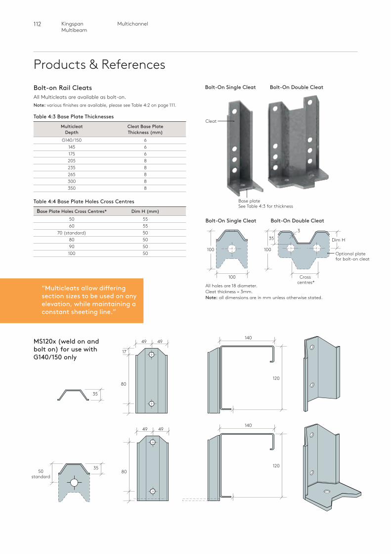
112 MultichannelKingspan Multibeam
Products & References
Base plateSee Table 4:3 for thickness
Bolt-On Single Cleat
Optional plate for bolt-on cleat
Dim H
100
35
Cross centres*
100
100
Bolt-On Double Cleat
All holes are 18 diameter.Cleat thickness = 3mm.Note: all dimensions are in mm unless otherwise stated.
Cleat
“Multicleats allow differing section sizes to be used on any elevation, while maintaining a constant sheeting line.”
Bolt-on Rail CleatsAll Multicleats are available as bolt-on. Note: various finishes are available, please see Table 4:2 on page 111.
Table 4:3 Base Plate Thicknesses
Multicleat Cleat Base Plate Depth Thickness (mm) G140/150 6 145 6 175 6 205 8 235 8 265 8 300 8 350 8
Table 4:4 Base Plate Holes Cross Centres
Base Plate Holes Cross Centres* Dim H (mm) 50 55 60 55 70 (standard) 50 80 50 90 50 100 50
MS120x (weld on and bolt on) for use with G140/150 only
80
49 49
35
35
49 49
80
140
120
17
50 standard
140
120
Bolt-On Single Cleat Bolt-On Double Cleat
3
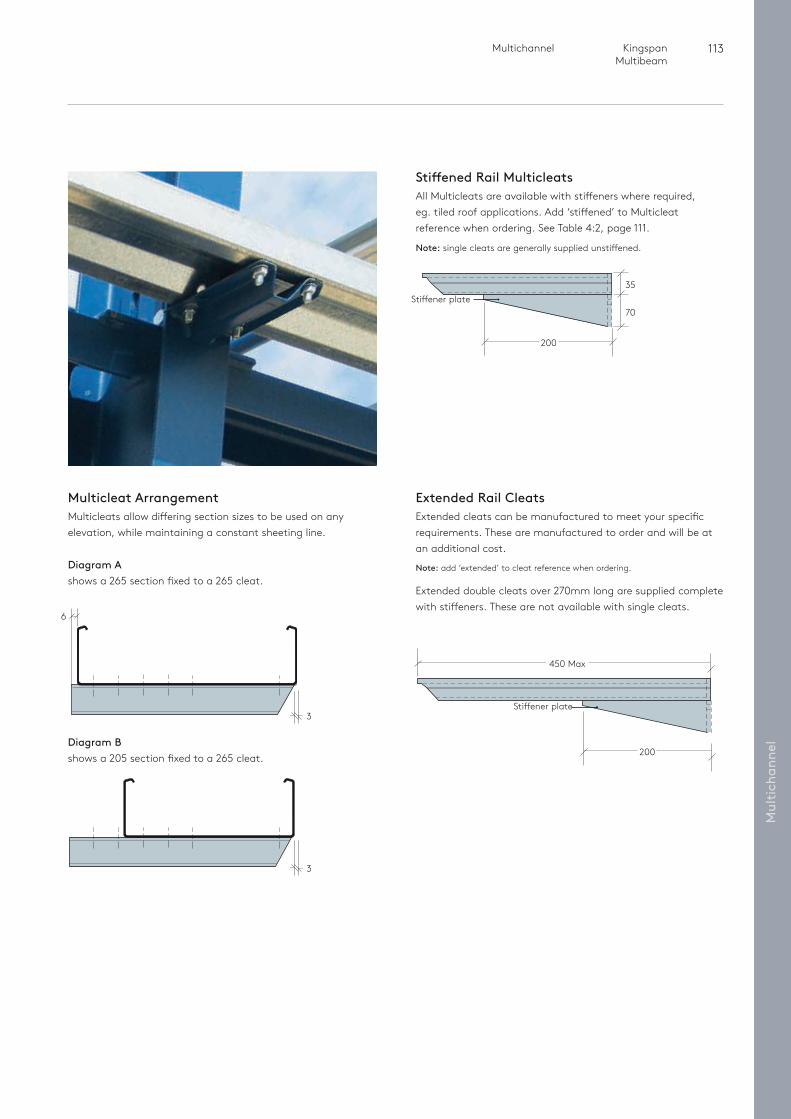
113 Multichannel Kingspan Multibeam
Mul
tich
anne
l
Stiffened Rail MulticleatsAll Multicleats are available with stiffeners where required, eg. tiled roof applications. Add ‘stiffened’ to Multicleat reference when ordering. See Table 4:2, page 111.
Note: single cleats are generally supplied unstiffened.
Multicleat ArrangementMulticleats allow differing section sizes to be used on any elevation, while maintaining a constant sheeting line.
Extended Rail CleatsExtended cleats can be manufactured to meet your specific requirements. These are manufactured to order and will be at an additional cost.
Note: add ‘extended’ to cleat reference when ordering.
Extended double cleats over 270mm long are supplied complete with stiffeners. These are not available with single cleats.
450 Max
200
Stiffener plate
Diagram Ashows a 265 section fixed to a 265 cleat.
Diagram Bshows a 205 section fixed to a 265 cleat.
200
6
3
3
70
35Stiffener plate
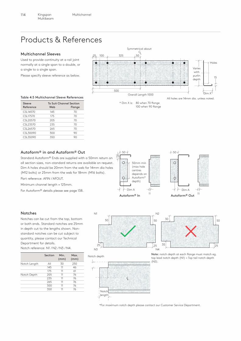
114 MultichannelKingspan Multibeam
Products & References
Autoform® In Autoform® Out
50
11Dim A
50mm min (max hole centres depends on Autoform® depth)
25
Dim A
* For maximum notch depth please contact our Customer Service Department.
Note: notch depth at each flange must match eg. top lead notch depth (N1) = Top tail notch depth (N2).
NotchesNotches can be cut from the top, bottom or both ends. Standard notches are 25mm in depth cut to the lengths shown. Non-standard notches can be cut subject to quantity, please contact our Technical Department for details. Notch reference: N1 / N2 / N3 / N4.
Section Min. Max. (mm) (mm)Notch Length All 30 250 145 11 46 175 11 61Notch Depth 205 11 76 235 11 76 265 11 76 300 11 76 350 11 76
Notch depth
N1 N2
N3 N4
CL
Notch length
* Dim X is: 80 when 70 flange 100 when 90 flange
11
50
5050
2525
5030
2535
Multichannel SleevesUsed to provide continuity at a rail joint normally at a single span to a double, or a single to a single span.
Please specify sleeve reference as below.
32510025 50
500Overall Length 1000
Symmetrical about C
L
All holes are 14mm dia. unless noted.Table 4:5 Multichannel Sleeve References
Sleeve To Suit Channel Section Reference Web Flange CSL14570 145 70 CSL17570 175 70 CSL20570 205 70 CSL23570 235 70 CSL26570 265 70 CSL30090 300 90 CSL35090 350 90
15
Holes
Varies with
purlin depth
Autoform® in and Autoform® OutStandard Autoform® Ends are supplied with a 50mm return on all section sizes, non-standard returns are available on request. Dim A holes should be 20mm from the web for 14mm dia holes (M12 bolts) or 25mm from the web for 18mm (M16 bolts).
Part reference: AFIN / AFOUT.
Minimum channel length = 125mm.
For Autoform® details please see page 138.
Dim X˚
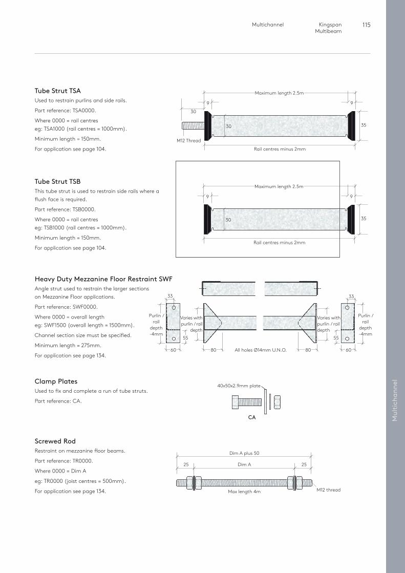
115 Multichannel Kingspan Multibeam
Mul
tich
anne
l
Tube Strut TSBThis tube strut is used to restrain side rails where a flush face is required.
Part reference: TSB0000.
Where 0000 = rail centres eg: TSB1000 (rail centres = 1000mm).
Minimum length = 150mm.
For application see page 104.
Tube Strut TSAUsed to restrain purlins and side rails.
Part reference: TSA0000.
Where 0000 = rail centres eg: TSA1000 (rail centres = 1000mm).
Minimum length = 150mm.
For application see page 104.
Clamp PlatesUsed to fix and complete a run of tube struts.
Part reference: CA.
CA
40x50x2.9mm plate
Heavy Duty Mezzanine Floor Restraint SWFAngle strut used to restrain the larger sections on Mezzanine Floor applications.
Part reference: SWF0000.
Where 0000 = overall length eg: SWF1500 (overall length = 1500mm).
Channel section size must be specified.
Minimum length = 275mm.
For application see page 134.
Varies with purlin / rail
depth
Varies with purlin / rail depth
All holes Ø14mm U.N.O.80 8060
33
55
Purlin / rail
depth -4mm
60
33
55
Purlin / rail
depth -4mm
Rail centres minus 2mm
30
M12 Thread
30
Maximum length 2.5m
9
35
35
9
Rail centres minus 2mm
30
Maximum length 2.5m
9 9
Screwed RodRestraint on mezzanine floor beams.
Part reference: TR0000.
Where 0000 = Dim A
eg: TR0000 (joist centres = 500mm).
For application see page 134. M12 thread
Dim A plus 50
Max length 4m
Dim A25 25
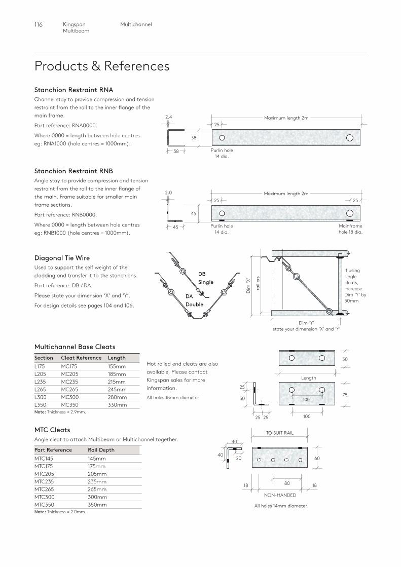
116 MultichannelKingspan Multibeam
Products & References
Stanchion Restraint RNBAngle stay to provide compression and tension restraint from the rail to the inner flange of the main. Frame suitable for smaller main frame sections.
Part reference: RNB0000.
Where 0000 = length between hole centreseg: RNB1000 (hole centres = 1000mm).
Stanchion Restraint RNAChannel stay to provide compression and tension restraint from the rail to the inner flange of the main frame.
Part reference: RNA0000.
Where 0000 = length between hole centreseg: RNA1000 (hole centres = 1000mm).
Maximum length 2m25
Purlin hole 14 dia.
38
2.4
38
Maximum length 2m2525
Purlin hole 14 dia.
Mainframe hole 18 dia.
45
2.0
45
Diagonal Tie WireUsed to support the self weight of the cladding and transfer it to the stanchions.
Part reference: DB / DA.
Please state your dimension ‘X’ and ‘Y’.
For design details see pages 104 and 106.
Hot rolled end cleats are also available, Please contact Kingspan sales for more information.
All holes 18mm diameter
Multichannel Base CleatsSection Cleat Reference LengthL175 MC175 155mmL205 MC205 185mmL235 MC235 215mmL265 MC265 245mmL300 MC300 280mmL350 MC350 330mmNote: Thickness = 2.9mm.
DA Double
DB Single
Dim ‘Y’ state your dimension ‘X’ and ‘Y’
rail
crs
Dim
‘X’
If using single cleats, increase Dim ‘Y’ by 50mm
40
MTC CleatsAngle cleat to attach Multibeam or Multichannel together.
Part Reference Rail DepthMTC145 145mmMTC175 175mmMTC205 205mmMTC235 235mmMTC265 265mmMTC300 300mmMTC350 350mmNote: Thickness = 2.0mm.
1818 80
TO SUIT RAIL
NON-HANDED
6040
All holes 14mm diameter
20
100
Length
7525
50
100
50
25 25
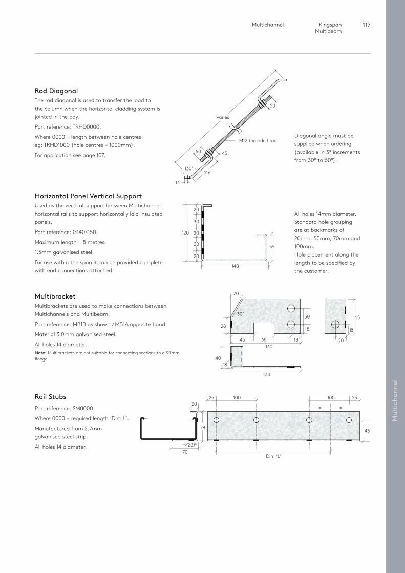
117 Multichannel Kingspan Multibeam
Mul
tich
anne
lRail StubsPart reference: SM0000.
Where 0000 = required length ‘Dim L’.
Manufactured from 2.7mm galvanised steel strip.
All holes 14 diameter.
2025 25
= =
43
100
Dim ‘L’
100
7023
78
Varies
4550
116
50
130˚
13
M12 threaded rodDiagonal angle must be supplied when ordering (available in 5° increments from 30° to 60°).
Horizontal Panel Vertical SupportUsed as the vertical support between Multichannel horizontal rails to support horizontally laid Insulated panels.
Part reference: G140/150.
Maximum length = 8 metres.
1.5mm galvanised steel.
For use within the span it can be provided complete with end connections attached.
MultibracketMultibrackets are used to make connections between Multichannels and Multibeam.
Part reference: MB1B as shown / MB1A opposite hand.
Material 3.0mm galvanised steel.
All holes 14 diameter.Note: Multibrackets are not suitable for connecting sections to a 90mm flange.
1840
130
30
38
30˚
28
130
18
1843
20
65
18
20
Rod DiagonalThe rod diagonal is used to transfer the load to the column when the horizontal cladding system is jointed in the bay.
Part reference: TRHD0000.
Where 0000 = length between hole centreseg: TRHD1000 (hole centres = 1000mm).
For application see page 107.
All holes 14mm diameter.Standard hole grouping are at backmarks of 20mm, 50mm, 70mm and 100mm. Hole placement along the length to be specified by the customer.
120
55
140
20
30
20
30
20
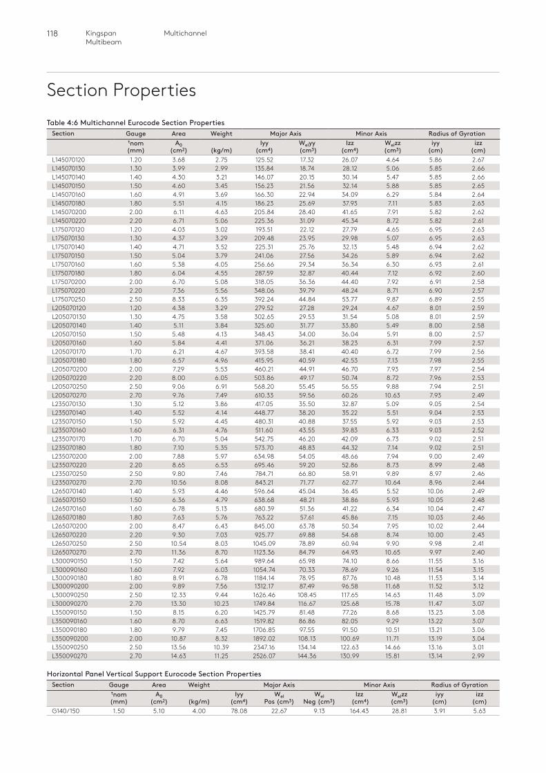
118 MultichannelKingspan Multibeam
Section PropertiesTable 4:6 Multichannel Eurocode Section Properties
Section Gauge Area Weight Major Axis Minor Axis Radius of Gyrationtnom (mm)
A0 (cm2)
(kg/m)
Iyy (cm4)
Welyy (cm3)
Izz (cm4)
Welzz (cm3)
iyy (cm)
izz (cm)
L145070120 1.20 3.68 2.75 125.52 17.32 26.07 4.64 5.86 2.67L145070130 1.30 3.99 2.99 135.84 18.74 28.12 5.06 5.85 2.66L145070140 1.40 4.30 3.21 146.07 20.15 30.14 5.47 5.85 2.66L145070150 1.50 4.60 3.45 156.23 21.56 32.14 5.88 5.85 2.65L145070160 1.60 4.91 3.69 166.30 22.94 34.09 6.29 5.84 2.64L145070180 1.80 5.51 4.15 186.23 25.69 37.93 7.11 5.83 2.63L145070200 2.00 6.11 4.63 205.84 28.40 41.65 7.91 5.82 2.62L145070220 2.20 6.71 5.06 225.36 31.09 45.34 8.72 5.82 2.61L175070120 1.20 4.03 3.02 193.51 22.12 27.79 4.65 6.95 2.63L175070130 1.30 4.37 3.29 209.48 23.95 29.98 5.07 6.95 2.63L175070140 1.40 4.71 3.52 225.31 25.76 32.13 5.48 6.94 2.62L175070150 1.50 5.04 3.79 241.06 27.56 34.26 5.89 6.94 2.62L175070160 1.60 5.38 4.05 256.66 29.34 36.34 6.30 6.93 2.61L175070180 1.80 6.04 4.55 287.59 32.87 40.44 7.12 6.92 2.60L175070200 2.00 6.70 5.08 318.05 36.36 44.40 7.92 6.91 2.58L175070220 2.20 7.36 5.56 348.06 39.79 48.24 8.71 6.90 2.57L175070250 2.50 8.33 6.35 392.24 44.84 53.77 9.87 6.89 2.55L205070120 1.20 4.38 3.29 279.52 27.28 29.24 4.67 8.01 2.59L205070130 1.30 4.75 3.58 302.65 29.53 31.54 5.08 8.01 2.59L205070140 1.40 5.11 3.84 325.60 31.77 33.80 5.49 8.00 2.58L205070150 1.50 5.48 4.13 348.43 34.00 36.04 5.91 8.00 2.57L205070160 1.60 5.84 4.41 371.06 36.21 38.23 6.31 7.99 2.57L205070170 1.70 6.21 4.67 393.58 38.41 40.40 6.72 7.99 2.56L205070180 1.80 6.57 4.96 415.95 40.59 42.53 7.13 7.98 2.55L205070200 2.00 7.29 5.53 460.21 44.91 46.70 7.93 7.97 2.54L205070220 2.20 8.00 6.05 503.86 49.17 50.74 8.72 7.96 2.53L205070250 2.50 9.06 6.91 568.20 55.45 56.55 9.88 7.94 2.51L205070270 2.70 9.76 7.49 610.33 59.56 60.26 10.63 7.93 2.49L235070130 1.30 5.12 3.86 417.05 35.50 32.87 5.09 9.05 2.54L235070140 1.40 5.52 4.14 448.77 38.20 35.22 5.51 9.04 2.53L235070150 1.50 5.92 4.45 480.31 40.88 37.55 5.92 9.03 2.53L235070160 1.60 6.31 4.76 511.60 43.55 39.83 6.33 9.03 2.52L235070170 1.70 6.70 5.04 542.75 46.20 42.09 6.73 9.02 2.51L235070180 1.80 7.10 5.35 573.70 48.83 44.32 7.14 9.02 2.51L235070200 2.00 7.88 5.97 634.98 54.05 48.66 7.94 9.00 2.49L235070220 2.20 8.65 6.53 695.46 59.20 52.86 8.73 8.99 2.48L235070250 2.50 9.80 7.46 784.71 66.80 58.91 9.89 8.97 2.46L235070270 2.70 10.56 8.08 843.21 71.77 62.77 10.64 8.96 2.44L265070140 1.40 5.93 4.46 596.64 45.04 36.45 5.52 10.06 2.49L265070150 1.50 6.36 4.79 638.68 48.21 38.86 5.93 10.05 2.48L265070160 1.60 6.78 5.13 680.39 51.36 41.22 6.34 10.04 2.47L265070180 1.80 7.63 5.76 763.22 57.61 45.86 7.15 10.03 2.46L265070200 2.00 8.47 6.43 845.00 63.78 50.34 7.95 10.02 2.44L265070220 2.20 9.30 7.03 925.77 69.88 54.68 8.74 10.00 2.43L265070250 2.50 10.54 8.03 1045.09 78.89 60.94 9.90 9.98 2.41L265070270 2.70 11.36 8.70 1123.36 84.79 64.93 10.65 9.97 2.40L300090150 1.50 7.42 5.64 989.64 65.98 74.10 8.66 11.55 3.16L300090160 1.60 7.92 6.03 1054.74 70.33 78.69 9.26 11.54 3.15L300090180 1.80 8.91 6.78 1184.14 78.95 87.76 10.48 11.53 3.14L300090200 2.00 9.89 7.56 1312.17 87.49 96.58 11.68 11.52 3.12L300090250 2.50 12.33 9.44 1626.46 108.45 117.65 14.63 11.48 3.09L300090270 2.70 13.30 10.23 1749.84 116.67 125.68 15.78 11.47 3.07L350090150 1.50 8.15 6.20 1425.79 81.48 77.26 8.68 13.23 3.08L350090160 1.60 8.70 6.63 1519.82 86.86 82.05 9.29 13.22 3.07L350090180 1.80 9.79 7.45 1706.85 97.55 91.50 10.51 13.21 3.06L350090200 2.00 10.87 8.32 1892.02 108.13 100.69 11.71 13.19 3.04L350090250 2.50 13.56 10.39 2347.16 134.14 122.63 14.66 13.16 3.01L350090270 2.70 14.63 11.25 2526.07 144.36 130.99 15.81 13.14 2.99
Horizontal Panel Vertical Support Eurocode Section PropertiesSection Gauge Area Weight Major Axis Minor Axis Radius of Gyration
tnom (mm)
A0 (cm2)
(kg/m)
Iyy (cm4)
Wel Pos (cm3)
Wel Neg (cm3)
Izz (cm4)
Welzz (cm3)
iyy (cm)
izz (cm)
G140/150 1.50 5.10 4.00 78.08 22.67 9.13 164.43 28.81 3.91 5.63
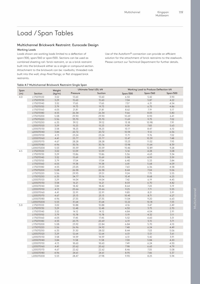
119 Multichannel Kingspan Multibeam
Mul
tich
anne
l
Load / Span Tables
Loads shown are working loads limited to a deflection of span/300, span/360 or span/500. Sections can be used as combined sheeting rail / brick restraint, or as a brick restraint built into the brickwork either as a single or compound section. Attachment to the brickwork can be: rawlbolts; threaded rods built into the wall; shop-fired fixings; or flat strapped brick restraints.
Multichannel Brickwork Restraint: Eurocode DesignWorking Loads
Table 4:7 Multichannel Brickwork Restraint Single Span
Span (m) Section
Weight (kg/m)
Ultimate Total UDL kN Working Load to Produce Deflection kNPressure Suction Span/300 Span/360 Span/500
4.0 L175070120 3.02 13.60 13.60 6.50 5.42 3.90L175070130 3.29 15.60 15.60 7.04 5.87 4.22L175070140 3.52 17.65 17.65 7.57 6.31 4.54L175070150 3.79 19.73 19.73 8.10 6.75 4.86L175070160 4.05 21.81 21.81 8.62 7.19 5.17L175070180 4.55 26.34 26.34 9.66 8.05 5.80L175070200 5.08 29.90 29.90 10.69 8.90 6.41L175070220 5.56 33.70 33.70 11.69 9.75 7.02L175070250 6.35 39.12 39.12 13.18 10.98 7.91L205070120 3.29 15.23 15.23 9.39 7.83 5.63L205070130 3.58 18.23 18.23 10.17 8.47 6.10L205070140 3.84 20.72 20.72 10.94 9.12 6.56L205070150 4.13 23.24 23.24 11.71 9.76 7.02L205070160 4.41 25.77 25.77 12.47 10.39 7.48L205070170 4.67 28.28 28.28 13.23 11.02 7.93L205070180 4.96 30.76 30.76 13.98 11.64 8.39L205070200 5.53 35.59 35.59 15.46 12.89 9.28
4.5 L175070120 3.02 12.09 12.09 5.14 4.28 3.08L175070130 3.29 13.86 13.86 5.56 4.63 3.34L175070140 3.52 15.69 15.69 5.98 4.99 3.59L175070150 3.79 17.54 17.54 6.40 5.33 3.84L175070160 4.05 19.38 19.38 6.81 5.68 4.09L175070180 4.55 23.05 23.05 7.63 6.36 4.58L175070200 5.08 26.58 26.58 8.44 7.04 5.06L175070220 5.56 29.95 29.51 9.24 7.70 5.55L175070250 6.35 34.77 33.16 10.41 8.68 6.25L205070120 3.29 14.04 14.04 7.42 6.19 4.45L205070130 3.58 16.21 16.21 8.03 6.70 4.82L205070140 3.84 18.42 18.42 8.64 7.20 5.19L205070150 4.13 20.66 20.66 9.25 7.71 5.55L205070160 4.41 22.91 22.91 9.85 8.21 5.91L205070170 4.67 25.13 25.13 10.45 8.71 6.27L205070180 4.96 27.35 27.35 11.04 9.20 6.63L205070200 5.53 31.64 31.64 12.22 10.18 7.33
5.0 L175070120 3.02 10.88 10.88 4.16 3.47 2.49L175070130 3.29 12.48 12.48 4.50 3.75 2.70L175070140 3.52 14.12 14.12 4.84 4.04 2.91L175070150 3.79 15.78 15.78 5.19 4.32 3.11L175070160 4.05 17.45 17.45 5.52 4.60 3.31L175070180 4.55 20.75 20.69 6.19 5.15 3.71L175070200 5.08 23.92 22.84 6.84 5.70 4.10L175070220 5.56 26.96 24.92 7.48 6.24 4.49L175070250 6.35 31.30 28.02 8.44 7.03 5.06L205070120 3.29 12.64 12.64 6.01 5.01 3.61L205070130 3.58 14.59 14.59 6.51 5.42 3.91L205070140 3.84 11.58 11.58 7.00 5.84 4.20L205070150 4.13 18.60 18.60 7.49 6.24 4.50L205070160 4.41 20.62 20.62 7.98 6.65 4.79L205070170 4.67 22.62 22.62 8.46 7.05 5.08L205070180 4.96 24.61 24.61 8.95 7.46 5.37L205070200 5.53 28.47 27.98 9.90 8.25 5.94
Use of the Autoform® connection can provide an efficient solution for the attachment of brick restraints to the steelwork. Please contact our Technical Department for further details.
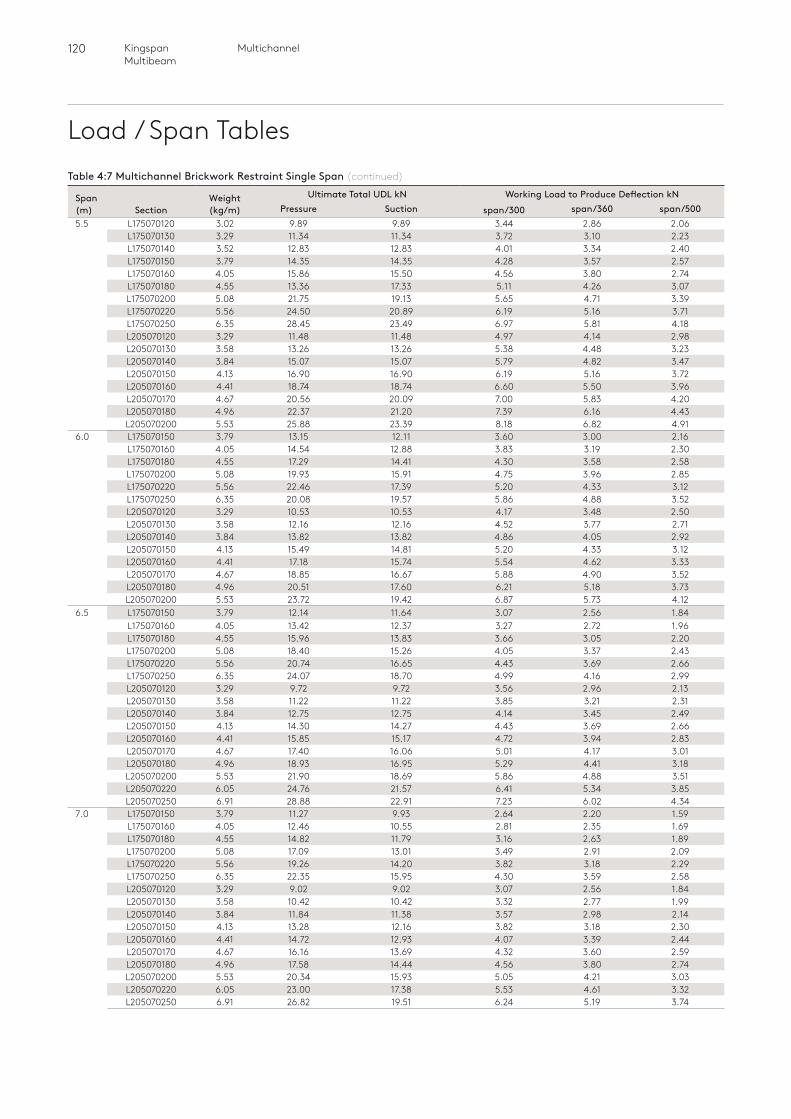
120 MultichannelKingspan Multibeam
Load / Span TablesTable 4:7 Multichannel Brickwork Restraint Single Span (continued)
Span (m) Section
Weight (kg/m)
Ultimate Total UDL kN Working Load to Produce Deflection kNPressure Suction span/300 span/360 span/500
5.5 L175070120 3.02 9.89 9.89 3.44 2.86 2.06L175070130 3.29 11.34 11.34 3.72 3.10 2.23L175070140 3.52 12.83 12.83 4.01 3.34 2.40L175070150 3.79 14.35 14.35 4.28 3.57 2.57L175070160 4.05 15.86 15.50 4.56 3.80 2.74L175070180 4.55 13.36 17.33 5.11 4.26 3.07L175070200 5.08 21.75 19.13 5.65 4.71 3.39L175070220 5.56 24.50 20.89 6.19 5.16 3.71L175070250 6.35 28.45 23.49 6.97 5.81 4.18L205070120 3.29 11.48 11.48 4.97 4.14 2.98L205070130 3.58 13.26 13.26 5.38 4.48 3.23L205070140 3.84 15.07 15.07 5.79 4.82 3.47L205070150 4.13 16.90 16.90 6.19 5.16 3.72L205070160 4.41 18.74 18.74 6.60 5.50 3.96L205070170 4.67 20.56 20.09 7.00 5.83 4.20L205070180 4.96 22.37 21.20 7.39 6.16 4.43L205070200 5.53 25.88 23.39 8.18 6.82 4.91
6.0 L175070150 3.79 13.15 12.11 3.60 3.00 2.16L175070160 4.05 14.54 12.88 3.83 3.19 2.30L175070180 4.55 17.29 14.41 4.30 3.58 2.58L175070200 5.08 19.93 15.91 4.75 3.96 2.85L175070220 5.56 22.46 17.39 5.20 4.33 3.12L175070250 6.35 20.08 19.57 5.86 4.88 3.52L205070120 3.29 10.53 10.53 4.17 3.48 2.50L205070130 3.58 12.16 12.16 4.52 3.77 2.71L205070140 3.84 13.82 13.82 4.86 4.05 2.92L205070150 4.13 15.49 14.81 5.20 4.33 3.12L205070160 4.41 17.18 15.74 5.54 4.62 3.33L205070170 4.67 18.85 16.67 5.88 4.90 3.52L205070180 4.96 20.51 17.60 6.21 5.18 3.73L205070200 5.53 23.72 19.42 6.87 5.73 4.12
6.5 L175070150 3.79 12.14 11.64 3.07 2.56 1.84L175070160 4.05 13.42 12.37 3.27 2.72 1.96L175070180 4.55 15.96 13.83 3.66 3.05 2.20L175070200 5.08 18.40 15.26 4.05 3.37 2.43L175070220 5.56 20.74 16.65 4.43 3.69 2.66L175070250 6.35 24.07 18.70 4.99 4.16 2.99L205070120 3.29 9.72 9.72 3.56 2.96 2.13L205070130 3.58 11.22 11.22 3.85 3.21 2.31L205070140 3.84 12.75 12.75 4.14 3.45 2.49L205070150 4.13 14.30 14.27 4.43 3.69 2.66L205070160 4.41 15.85 15.17 4.72 3.94 2.83L205070170 4.67 17.40 16.06 5.01 4.17 3.01L205070180 4.96 18.93 16.95 5.29 4.41 3.18L205070200 5.53 21.90 18.69 5.86 4.88 3.51L205070220 6.05 24.76 21.57 6.41 5.34 3.85L205070250 6.91 28.88 22.91 7.23 6.02 4.34
7.0 L175070150 3.79 11.27 9.93 2.64 2.20 1.59L175070160 4.05 12.46 10.55 2.81 2.35 1.69L175070180 4.55 14.82 11.79 3.16 2.63 1.89L175070200 5.08 17.09 13.01 3.49 2.91 2.09L175070220 5.56 19.26 14.20 3.82 3.18 2.29L175070250 6.35 22.35 15.95 4.30 3.59 2.58L205070120 3.29 9.02 9.02 3.07 2.56 1.84L205070130 3.58 10.42 10.42 3.32 2.77 1.99L205070140 3.84 11.84 11.38 3.57 2.98 2.14L205070150 4.13 13.28 12.16 3.82 3.18 2.30L205070160 4.41 14.72 12.93 4.07 3.39 2.44L205070170 4.67 16.16 13.69 4.32 3.60 2.59L205070180 4.96 17.58 14.44 4.56 3.80 2.74L205070200 5.53 20.34 15.93 5.05 4.21 3.03L205070220 6.05 23.00 17.38 5.53 4.61 3.32L205070250 6.91 26.82 19.51 6.24 5.19 3.74
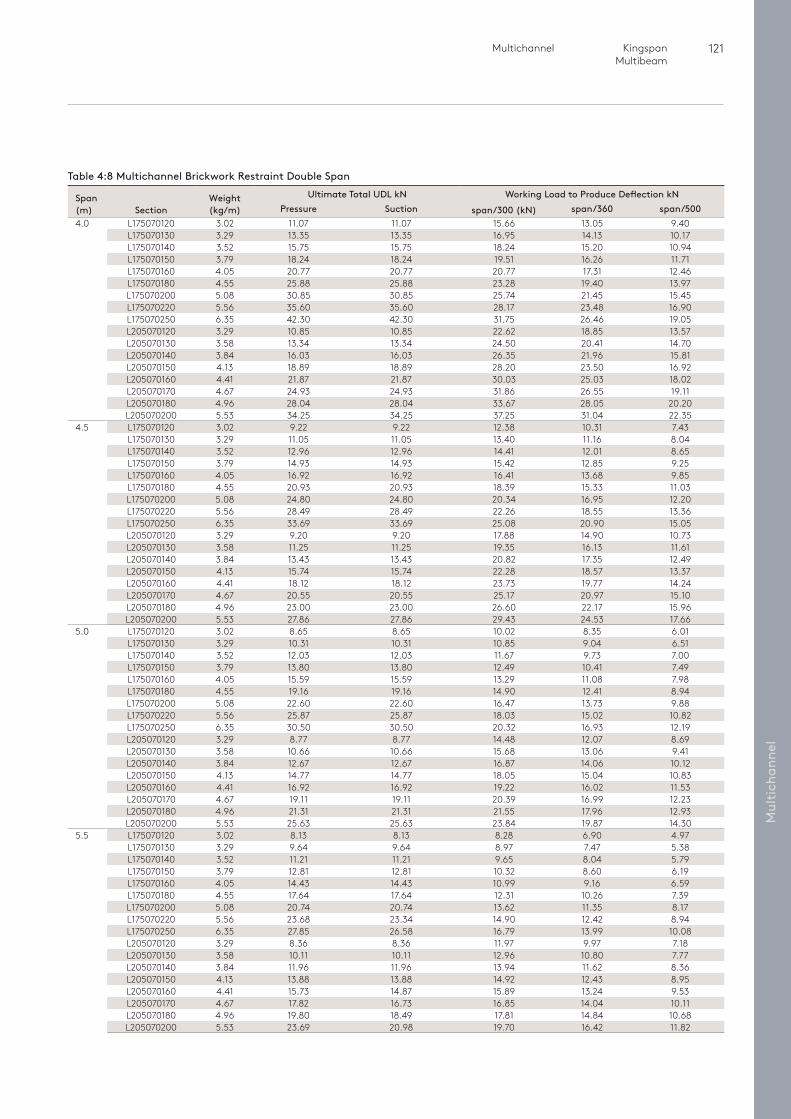
121 Multichannel Kingspan Multibeam
Mul
tich
anne
l
Table 4:8 Multichannel Brickwork Restraint Double Span
Span (m) Section
Weight (kg/m)
Ultimate Total UDL kN Working Load to Produce Deflection kNPressure Suction span/300 (kN) span/360 span/500
4.0 L175070120 3.02 11.07 11.07 15.66 13.05 9.40L175070130 3.29 13.35 13.35 16.95 14.13 10.17L175070140 3.52 15.75 15.75 18.24 15.20 10.94L175070150 3.79 18.24 18.24 19.51 16.26 11.71L175070160 4.05 20.77 20.77 20.77 17.31 12.46L175070180 4.55 25.88 25.88 23.28 19.40 13.97L175070200 5.08 30.85 30.85 25.74 21.45 15.45L175070220 5.56 35.60 35.60 28.17 23.48 16.90L175070250 6.35 42.30 42.30 31.75 26.46 19.05L205070120 3.29 10.85 10.85 22.62 18.85 13.57L205070130 3.58 13.34 13.34 24.50 20.41 14.70L205070140 3.84 16.03 16.03 26.35 21.96 15.81L205070150 4.13 18.89 18.89 28.20 23.50 16.92L205070160 4.41 21.87 21.87 30.03 25.03 18.02L205070170 4.67 24.93 24.93 31.86 26.55 19.11L205070180 4.96 28.04 28.04 33.67 28.05 20.20L205070200 5.53 34.25 34.25 37.25 31.04 22.35
4.5 L175070120 3.02 9.22 9.22 12.38 10.31 7.43L175070130 3.29 11.05 11.05 13.40 11.16 8.04L175070140 3.52 12.96 12.96 14.41 12.01 8.65L175070150 3.79 14.93 14.93 15.42 12.85 9.25L175070160 4.05 16.92 16.92 16.41 13.68 9.85L175070180 4.55 20.93 20.93 18.39 15.33 11.03L175070200 5.08 24.80 24.80 20.34 16.95 12.20L175070220 5.56 28.49 28.49 22.26 18.55 13.36L175070250 6.35 33.69 33.69 25.08 20.90 15.05L205070120 3.29 9.20 9.20 17.88 14.90 10.73L205070130 3.58 11.25 11.25 19.35 16.13 11.61L205070140 3.84 13.43 13.43 20.82 17.35 12.49L205070150 4.13 15.74 15.74 22.28 18.57 13.37L205070160 4.41 18.12 18.12 23.73 19.77 14.24L205070170 4.67 20.55 20.55 25.17 20.97 15.10L205070180 4.96 23.00 23.00 26.60 22.17 15.96L205070200 5.53 27.86 27.86 29.43 24.53 17.66
5.0 L175070120 3.02 8.65 8.65 10.02 8.35 6.01L175070130 3.29 10.31 10.31 10.85 9.04 6.51L175070140 3.52 12.03 12.03 11.67 9.73 7.00L175070150 3.79 13.80 13.80 12.49 10.41 7.49L175070160 4.05 15.59 15.59 13.29 11.08 7.98L175070180 4.55 19.16 19.16 14.90 12.41 8.94L175070200 5.08 22.60 22.60 16.47 13.73 9.88L175070220 5.56 25.87 25.87 18.03 15.02 10.82L175070250 6.35 30.50 30.50 20.32 16.93 12.19L205070120 3.29 8.77 8.77 14.48 12.07 8.69L205070130 3.58 10.66 10.66 15.68 13.06 9.41L205070140 3.84 12.67 12.67 16.87 14.06 10.12L205070150 4.13 14.77 14.77 18.05 15.04 10.83L205070160 4.41 16.92 16.92 19.22 16.02 11.53L205070170 4.67 19.11 19.11 20.39 16.99 12.23L205070180 4.96 21.31 21.31 21.55 17.96 12.93L205070200 5.53 25.63 25.63 23.84 19.87 14.30
5.5 L175070120 3.02 8.13 8.13 8.28 6.90 4.97L175070130 3.29 9.64 9.64 8.97 7.47 5.38L175070140 3.52 11.21 11.21 9.65 8.04 5.79L175070150 3.79 12.81 12.81 10.32 8.60 6.19L175070160 4.05 14.43 14.43 10.99 9.16 6.59L175070180 4.55 17.64 17.64 12.31 10.26 7.39L175070200 5.08 20.74 20.74 13.62 11.35 8.17L175070220 5.56 23.68 23.34 14.90 12.42 8.94L175070250 6.35 27.85 26.58 16.79 13.99 10.08L205070120 3.29 8.36 8.36 11.97 9.97 7.18L205070130 3.58 10.11 10.11 12.96 10.80 7.77L205070140 3.84 11.96 11.96 13.94 11.62 8.36L205070150 4.13 13.88 13.88 14.92 12.43 8.95L205070160 4.41 15.73 14.87 15.89 13.24 9.53L205070170 4.67 17.82 16.73 16.85 14.04 10.11L205070180 4.96 19.80 18.49 17.81 14.84 10.68L205070200 5.53 23.69 20.98 19.70 16.42 11.82
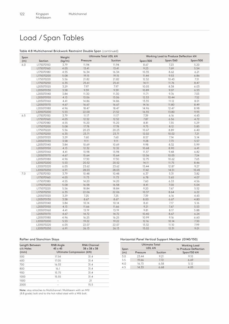
122 MultichannelKingspan Multibeam
Load / Span Tables
Rafter and Stanchion Stays
Length Between RNB Angle RNA Channelc/c Holes 45 x 45 38 x 38 x 38(mm) Ultimate Compression (kN) 500 17.54 31.4600 17.05 31.4700 16.55 31.4800 16.1 31.4900 15.75 31.41000 15.55 31.41500 – 212000 – 15.5
Note: stay attaches to Multichannel / Multibeam with an M12 (8.8 grade) bolt and to the hot-rolled steel with a M16 bolt.
Table 4:8 Multichannel Brickwork Restraint Double Span (continued)
Span (m) Section
Weight (kg/m)
Ultimate Total UDL kN Working Load to Produce Deflection kNPressure Suction Span/300 Span/360 Span/500
6.0 L175070150 3.79 11.94 11.94 8.67 7.23 5.20L175070160 4.05 13.41 13.41 9.23 7.69 5.54L175070180 4.55 16.34 16.34 10.35 8.62 6.21L175070200 5.08 19.15 19.15 11.44 9.53 6.86L175070220 5.56 21.82 21.82 12.52 10.43 7.51L175070250 6.35 25.61 25.61 14.11 11.76 8.47L205070120 3.29 7.97 7.97 10.05 8.38 6.03L205070130 3.58 9.59 9.59 10.89 9.07 6.53L205070140 3.84 11.30 11.30 11.71 9.76 7.03L205070150 4.13 13.06 13.06 12.53 10.44 7.52L205070160 4.41 14.86 14.86 13.35 11.12 8.01L205070170 4.67 16.67 16.67 14.16 11.80 8.49L205070180 4.96 18.47 18.47 14.96 12.47 8.98L205070200 5.53 22.00 21.52 16.55 13.80 9.93
6.5 L175070150 3.79 11.17 11.17 7.39 6.16 4.43L175070160 4.05 12.52 12.52 7.87 6.56 4.72L175070180 4.55 15.20 15.20 8.81 7.35 5.29L175070200 5.08 17.78 17.78 9.75 8.12 5.85L175070220 5.56 20.23 20.23 10.67 8.89 6.40L175070250 6.35 23.71 23.71 12.02 10.02 7.21L205070120 3.29 7.60 7.60 8.57 7.14 5.14L205070130 3.58 9.11 9.11 9.28 7.73 5.57L205070140 3.84 10.69 10.69 9.98 8.32 5.99L205070150 4.13 12.32 12.32 10.68 8.90 6.41L205070160 4.41 13.98 13.98 11.37 9.48 6.82L205070170 4.67 15.64 15.64 12.06 10.05 7.24L205070180 4.96 17.30 17.30 12.75 10.62 7.65L205070200 5.53 20.52 20.52 14.11 11.75 8.46L205070220 6.05 23.62 23.62 15.44 12.87 9.27L205070250 6.91 28.03 28.03 17.42 14.51 10.45
7.0 L175070150 3.79 10.48 10.48 6.37 5.31 3.82L175070160 4.05 11.73 11.73 6.78 5.65 4.07L175070180 4.55 14.20 14.20 7.60 6.33 4.56L175070200 5.08 16.58 16.58 8.41 7.00 5.04L175070220 5.56 18.84 18.84 9.20 7.67 5.52L175070250 6.35 22.06 22.06 10.37 8.64 6.22L205070120 3.29 7.25 7.25 7.39 6.16 4.43L205070130 3.58 8.67 8.67 8.00 6.67 4.80L205070140 3.84 10.14 10.14 8.61 7.17 5.16L205070150 4.13 11.66 11.66 9.21 7.67 5.53L205070160 4.41 13.19 13.19 9.81 8.17 5.88L205070170 4.67 14.72 14.72 10.40 8.67 6.24L205070180 4.96 16.25 16.25 10.99 9.16 6.60L205070200 5.53 19.22 19.22 12.16 10.14 7.30L205070220 6.05 22.07 22.07 13.32 11.10 7.99L205070250 6.91 26.13 26.13 15.02 12.51 9.01
Span (m)
Ultimate Total UDL kN
Working Load to Produce Deflection
Span/150 kNPressure Suction3.0 23.44 9.21 9.103.5 19.66 7.72 6.694.0 16.73 6.58 5.124.5 14.33 6.68 4.05
Horizontal Panel Vertical Support Member (G140/150)
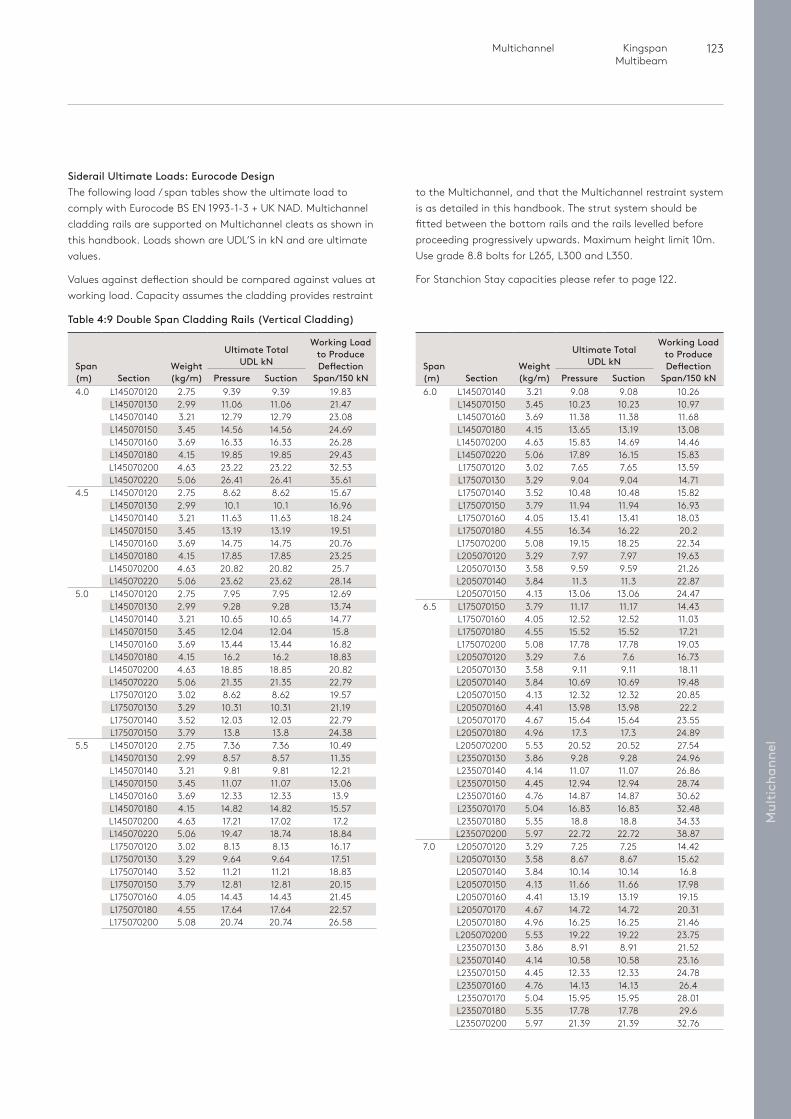
123 Multichannel Kingspan Multibeam
Mul
tich
anne
l
Siderail Ultimate Loads: Eurocode DesignThe following load / span tables show the ultimate load to comply with Eurocode BS EN 1993-1-3 + UK NAD. Multichannel cladding rails are supported on Multichannel cleats as shown in this handbook. Loads shown are UDL’S in kN and are ultimate values.
Values against deflection should be compared against values at working load. Capacity assumes the cladding provides restraint
to the Multichannel, and that the Multichannel restraint system is as detailed in this handbook. The strut system should be fitted between the bottom rails and the rails levelled before proceeding progressively upwards. Maximum height limit 10m. Use grade 8.8 bolts for L265, L300 and L350.
For Stanchion Stay capacities please refer to page 122.
Table 4:9 Double Span Cladding Rails (Vertical Cladding)
Span (m)
Section
Weight (kg/m)
Ultimate Total UDL kN
Working Load to Produce Deflection
Span/150 kNPressure Suction4.0 L145070120 2.75 9.39 9.39 19.83
L145070130 2.99 11.06 11.06 21.47L145070140 3.21 12.79 12.79 23.08L145070150 3.45 14.56 14.56 24.69L145070160 3.69 16.33 16.33 26.28L145070180 4.15 19.85 19.85 29.43L145070200 4.63 23.22 23.22 32.53L145070220 5.06 26.41 26.41 35.61
4.5 L145070120 2.75 8.62 8.62 15.67L145070130 2.99 10.1 10.1 16.96L145070140 3.21 11.63 11.63 18.24L145070150 3.45 13.19 13.19 19.51L145070160 3.69 14.75 14.75 20.76L145070180 4.15 17.85 17.85 23.25L145070200 4.63 20.82 20.82 25.7L145070220 5.06 23.62 23.62 28.14
5.0 L145070120 2.75 7.95 7.95 12.69L145070130 2.99 9.28 9.28 13.74L145070140 3.21 10.65 10.65 14.77L145070150 3.45 12.04 12.04 15.8L145070160 3.69 13.44 13.44 16.82L145070180 4.15 16.2 16.2 18.83L145070200 4.63 18.85 18.85 20.82L145070220 5.06 21.35 21.35 22.79L175070120 3.02 8.62 8.62 19.57L175070130 3.29 10.31 10.31 21.19L175070140 3.52 12.03 12.03 22.79L175070150 3.79 13.8 13.8 24.38
5.5 L145070120 2.75 7.36 7.36 10.49L145070130 2.99 8.57 8.57 11.35L145070140 3.21 9.81 9.81 12.21L145070150 3.45 11.07 11.07 13.06L145070160 3.69 12.33 12.33 13.9L145070180 4.15 14.82 14.82 15.57L145070200 4.63 17.21 17.02 17.2L145070220 5.06 19.47 18.74 18.84L175070120 3.02 8.13 8.13 16.17L175070130 3.29 9.64 9.64 17.51L175070140 3.52 11.21 11.21 18.83L175070150 3.79 12.81 12.81 20.15L175070160 4.05 14.43 14.43 21.45L175070180 4.55 17.64 17.64 22.57L175070200 5.08 20.74 20.74 26.58
Span (m)
Section
Weight (kg/m)
Ultimate Total UDL kN
Working Load to Produce Deflection
Span/150 kNPressure Suction6.0 L145070140 3.21 9.08 9.08 10.26
L145070150 3.45 10.23 10.23 10.97L145070160 3.69 11.38 11.38 11.68L145070180 4.15 13.65 13.19 13.08L145070200 4.63 15.83 14.69 14.46L145070220 5.06 17.89 16.15 15.83L175070120 3.02 7.65 7.65 13.59L175070130 3.29 9.04 9.04 14.71L175070140 3.52 10.48 10.48 15.82L175070150 3.79 11.94 11.94 16.93L175070160 4.05 13.41 13.41 18.03L175070180 4.55 16.34 16.22 20.2L175070200 5.08 19.15 18.25 22.34L205070120 3.29 7.97 7.97 19.63L205070130 3.58 9.59 9.59 21.26L205070140 3.84 11.3 11.3 22.87L205070150 4.13 13.06 13.06 24.47
6.5 L175070150 3.79 11.17 11.17 14.43L175070160 4.05 12.52 12.52 11.03L175070180 4.55 15.52 15.52 17.21L175070200 5.08 17.78 17.78 19.03L205070120 3.29 7.6 7.6 16.73L205070130 3.58 9.11 9.11 18.11L205070140 3.84 10.69 10.69 19.48L205070150 4.13 12.32 12.32 20.85L205070160 4.41 13.98 13.98 22.2L205070170 4.67 15.64 15.64 23.55L205070180 4.96 17.3 17.3 24.89L205070200 5.53 20.52 20.52 27.54L235070130 3.86 9.28 9.28 24.96L235070140 4.14 11.07 11.07 26.86L235070150 4.45 12.94 12.94 28.74L235070160 4.76 14.87 14.87 30.62L235070170 5.04 16.83 16.83 32.48L235070180 5.35 18.8 18.8 34.33L235070200 5.97 22.72 22.72 38.87
7.0 L205070120 3.29 7.25 7.25 14.42L205070130 3.58 8.67 8.67 15.62L205070140 3.84 10.14 10.14 16.8L205070150 4.13 11.66 11.66 17.98L205070160 4.41 13.19 13.19 19.15L205070170 4.67 14.72 14.72 20.31L205070180 4.96 16.25 16.25 21.46L205070200 5.53 19.22 19.22 23.75L235070130 3.86 8.91 8.91 21.52L235070140 4.14 10.58 10.58 23.16L235070150 4.45 12.33 12.33 24.78L235070160 4.76 14.13 14.13 26.4L235070170 5.04 15.95 15.95 28.01L235070180 5.35 17.78 17.78 29.6L235070200 5.97 21.39 21.39 32.76
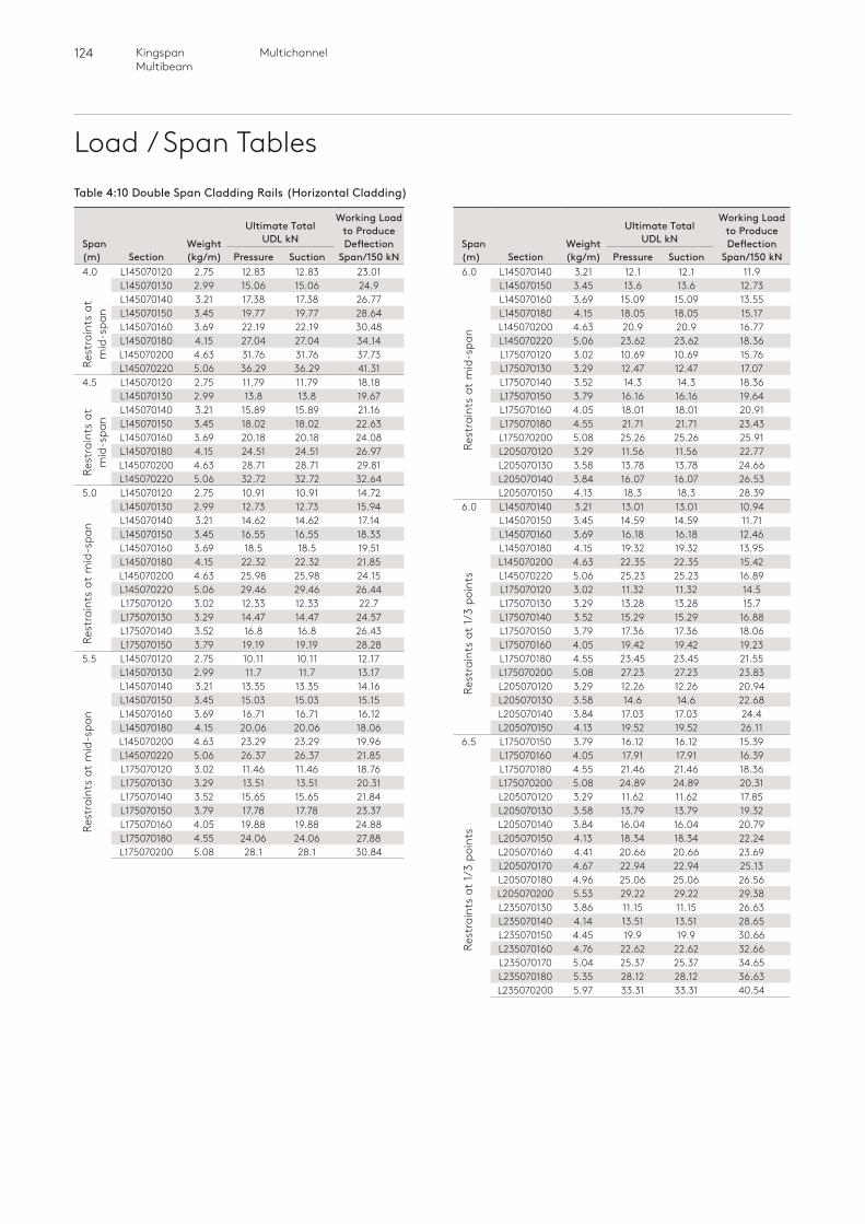
124 MultichannelKingspan Multibeam
Load / Span Tables
Rest
rain
ts a
t m
id-s
pan
Rest
rain
ts a
t 1/3
poi
nts
Rest
rain
ts a
t 1/3
poi
nts
Rest
rain
ts a
t
mid
-spa
nRe
stra
ints
at
m
id-s
pan
Rest
rain
ts a
t m
id-s
pan
Rest
rain
ts a
t m
id-s
pan
Table 4:10 Double Span Cladding Rails (Horizontal Cladding)
Span (m)
Section
Weight (kg/m)
Ultimate Total UDL kN
Working Load to Produce Deflection
Span/150 kNPressure Suction4.0 L145070120 2.75 12.83 12.83 23.01
L145070130 2.99 15.06 15.06 24.9L145070140 3.21 17.38 17.38 26.77L145070150 3.45 19.77 19.77 28.64L145070160 3.69 22.19 22.19 30.48L145070180 4.15 27.04 27.04 34.14L145070200 4.63 31.76 31.76 37.73L145070220 5.06 36.29 36.29 41.31
4.5 L145070120 2.75 11.79 11.79 18.18L145070130 2.99 13.8 13.8 19.67L145070140 3.21 15.89 15.89 21.16L145070150 3.45 18.02 18.02 22.63L145070160 3.69 20.18 20.18 24.08L145070180 4.15 24.51 24.51 26.97L145070200 4.63 28.71 28.71 29.81L145070220 5.06 32.72 32.72 32.64
5.0 L145070120 2.75 10.91 10.91 14.72L145070130 2.99 12.73 12.73 15.94L145070140 3.21 14.62 14.62 17.14L145070150 3.45 16.55 16.55 18.33L145070160 3.69 18.5 18.5 19.51L145070180 4.15 22.32 22.32 21.85L145070200 4.63 25.98 25.98 24.15L145070220 5.06 29.46 29.46 26.44L175070120 3.02 12.33 12.33 22.7L175070130 3.29 14.47 14.47 24.57L175070140 3.52 16.8 16.8 26.43L175070150 3.79 19.19 19.19 28.28
5.5 L145070120 2.75 10.11 10.11 12.17L145070130 2.99 11.7 11.7 13.17L145070140 3.21 13.35 13.35 14.16L145070150 3.45 15.03 15.03 15.15L145070160 3.69 16.71 16.71 16.12L145070180 4.15 20.06 20.06 18.06L145070200 4.63 23.29 23.29 19.96L145070220 5.06 26.37 26.37 21.85L175070120 3.02 11.46 11.46 18.76L175070130 3.29 13.51 13.51 20.31L175070140 3.52 15.65 15.65 21.84L175070150 3.79 17.78 17.78 23.37L175070160 4.05 19.88 19.88 24.88L175070180 4.55 24.06 24.06 27.88L175070200 5.08 28.1 28.1 30.84
Span (m)
Section
Weight (kg/m)
Ultimate Total UDL kN
Working Load to Produce Deflection
Span/150 kNPressure Suction6.0 L145070140 3.21 12.1 12.1 11.9
L145070150 3.45 13.6 13.6 12.73L145070160 3.69 15.09 15.09 13.55L145070180 4.15 18.05 18.05 15.17L145070200 4.63 20.9 20.9 16.77L145070220 5.06 23.62 23.62 18.36L175070120 3.02 10.69 10.69 15.76L175070130 3.29 12.47 12.47 17.07L175070140 3.52 14.3 14.3 18.36L175070150 3.79 16.16 16.16 19.64L175070160 4.05 18.01 18.01 20.91L175070180 4.55 21.71 21.71 23.43L175070200 5.08 25.26 25.26 25.91L205070120 3.29 11.56 11.56 22.77L205070130 3.58 13.78 13.78 24.66L205070140 3.84 16.07 16.07 26.53L205070150 4.13 18.3 18.3 28.39
6.0 L145070140 3.21 13.01 13.01 10.94L145070150 3.45 14.59 14.59 11.71L145070160 3.69 16.18 16.18 12.46L145070180 4.15 19.32 19.32 13.95L145070200 4.63 22.35 22.35 15.42L145070220 5.06 25.23 25.23 16.89L175070120 3.02 11.32 11.32 14.5L175070130 3.29 13.28 13.28 15.7L175070140 3.52 15.29 15.29 16.88L175070150 3.79 17.36 17.36 18.06L175070160 4.05 19.42 19.42 19.23L175070180 4.55 23.45 23.45 21.55L175070200 5.08 27.23 27.23 23.83L205070120 3.29 12.26 12.26 20.94L205070130 3.58 14.6 14.6 22.68L205070140 3.84 17.03 17.03 24.4L205070150 4.13 19.52 19.52 26.11
6.5 L175070150 3.79 16.12 16.12 15.39L175070160 4.05 17.91 17.91 16.39L175070180 4.55 21.46 21.46 18.36L175070200 5.08 24.89 24.89 20.31L205070120 3.29 11.62 11.62 17.85L205070130 3.58 13.79 13.79 19.32L205070140 3.84 16.04 16.04 20.79L205070150 4.13 18.34 18.34 22.24L205070160 4.41 20.66 20.66 23.69L205070170 4.67 22.94 22.94 25.13L205070180 4.96 25.06 25.06 26.56L205070200 5.53 29.22 29.22 29.38L235070130 3.86 11.15 11.15 26.63L235070140 4.14 13.51 13.51 28.65L235070150 4.45 19.9 19.9 30.66L235070160 4.76 22.62 22.62 32.66L235070170 5.04 25.37 25.37 34.65L235070180 5.35 28.12 28.12 36.63L235070200 5.97 33.31 33.31 40.54
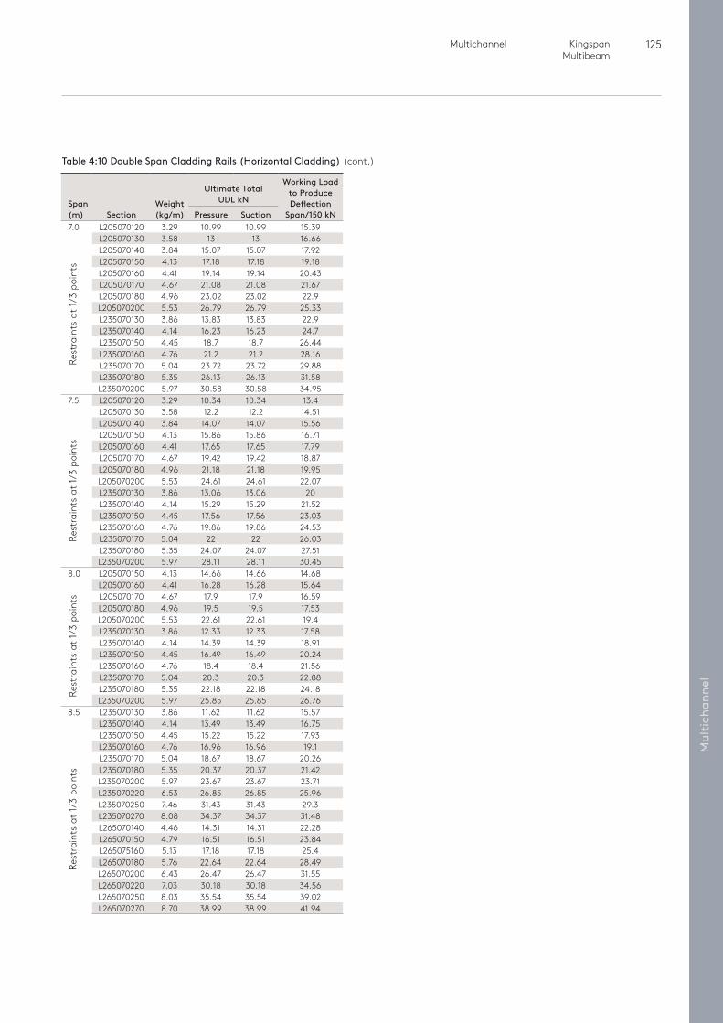
125 Multichannel Kingspan Multibeam
Mul
tich
anne
l
Rest
rain
ts a
t 1/3
poi
nts
Rest
rain
ts a
t 1/3
poi
nts
Rest
rain
ts a
t 1/3
poi
nts
Table 4:10 Double Span Cladding Rails (Horizontal Cladding) (cont.)
Span (m)
Section
Weight (kg/m)
Ultimate Total UDL kN
Working Load to Produce Deflection
Span/150 kNPressure Suction7.0 L205070120 3.29 10.99 10.99 15.39
L205070130 3.58 13 13 16.66L205070140 3.84 15.07 15.07 17.92L205070150 4.13 17.18 17.18 19.18L205070160 4.41 19.14 19.14 20.43L205070170 4.67 21.08 21.08 21.67L205070180 4.96 23.02 23.02 22.9L205070200 5.53 26.79 26.79 25.33L235070130 3.86 13.83 13.83 22.9L235070140 4.14 16.23 16.23 24.7L235070150 4.45 18.7 18.7 26.44L235070160 4.76 21.2 21.2 28.16L235070170 5.04 23.72 23.72 29.88L235070180 5.35 26.13 26.13 31.58L235070200 5.97 30.58 30.58 34.95
7.5 L205070120 3.29 10.34 10.34 13.4L205070130 3.58 12.2 12.2 14.51L205070140 3.84 14.07 14.07 15.56L205070150 4.13 15.86 15.86 16.71L205070160 4.41 17.65 17.65 17.79L205070170 4.67 19.42 19.42 18.87L205070180 4.96 21.18 21.18 19.95L205070200 5.53 24.61 24.61 22.07L235070130 3.86 13.06 13.06 20L235070140 4.14 15.29 15.29 21.52L235070150 4.45 17.56 17.56 23.03L235070160 4.76 19.86 19.86 24.53L235070170 5.04 22 22 26.03L235070180 5.35 24.07 24.07 27.51L235070200 5.97 28.11 28.11 30.45
8.0 L205070150 4.13 14.66 14.66 14.68L205070160 4.41 16.28 16.28 15.64L205070170 4.67 17.9 17.9 16.59L205070180 4.96 19.5 19.5 17.53L205070200 5.53 22.61 22.61 19.4L235070130 3.86 12.33 12.33 17.58L235070140 4.14 14.39 14.39 18.91L235070150 4.45 16.49 16.49 20.24L235070160 4.76 18.4 18.4 21.56L235070170 5.04 20.3 20.3 22.88L235070180 5.35 22.18 22.18 24.18L235070200 5.97 25.85 25.85 26.76
8.5 L235070130 3.86 11.62 11.62 15.57L235070140 4.14 13.49 13.49 16.75L235070150 4.45 15.22 15.22 17.93L235070160 4.76 16.96 16.96 19.1L235070170 5.04 18.67 18.67 20.26L235070180 5.35 20.37 20.37 21.42L235070200 5.97 23.67 23.67 23.71L235070220 6.53 26.85 26.85 25.96L235070250 7.46 31.43 31.43 29.3L235070270 8.08 34.37 34.37 31.48L265070140 4.46 14.31 14.31 22.28L265070150 4.79 16.51 16.51 23.84L265075160 5.13 17.18 17.18 25.4L265070180 5.76 22.64 22.64 28.49L265070200 6.43 26.47 26.47 31.55L265070220 7.03 30.18 30.18 34.56L265070250 8.03 35.54 35.54 39.02L265070270 8.70 38.99 38.99 41.94
Rest
rain
ts a
t 1/3
poi
nts
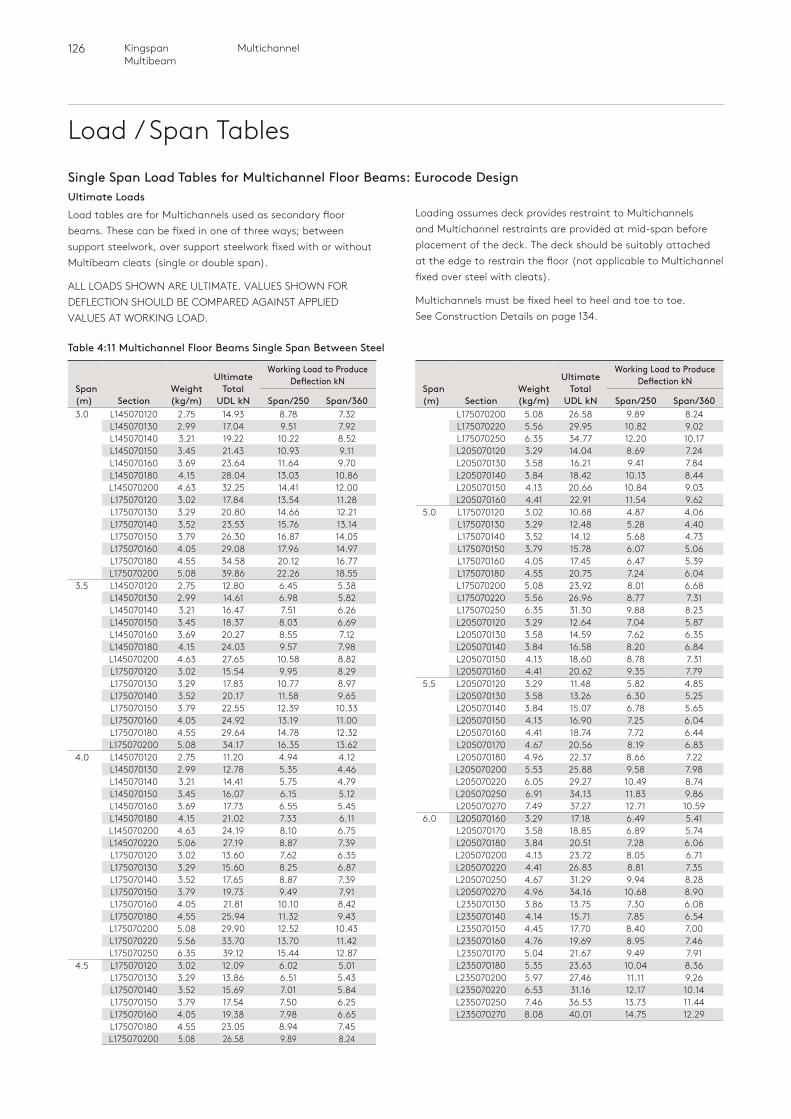
126 MultichannelKingspan Multibeam
Load / Span Tables
Ultimate LoadsLoad tables are for Multichannels used as secondary floor beams. These can be fixed in one of three ways; between support steelwork, over support steelwork fixed with or without Multibeam cleats (single or double span).
ALL LOADS SHOWN ARE ULTIMATE. VALUES SHOWN FOR DEFLECTION SHOULD BE COMPARED AGAINST APPLIED VALUES AT WORKING LOAD.
Single Span Load Tables for Multichannel Floor Beams: Eurocode Design Loading assumes deck provides restraint to Multichannels and Multichannel restraints are provided at mid-span before placement of the deck. The deck should be suitably attached at the edge to restrain the floor (not applicable to Multichannel fixed over steel with cleats).
Multichannels must be fixed heel to heel and toe to toe. See Construction Details on page 134.
Table 4:11 Multichannel Floor Beams Single Span Between Steel
Span (m)
Section
Weight (kg/m)
Ultimate Total
UDL kN
Working Load to Produce Deflection kN
Span/250 Span/3603.0 L145070120 2.75 14.93 8.78 7.32
L145070130 2.99 17.04 9.51 7.92L145070140 3.21 19.22 10.22 8.52L145070150 3.45 21.43 10.93 9.11L145070160 3.69 23.64 11.64 9.70L145070180 4.15 28.04 13.03 10.86L145070200 4.63 32.25 14.41 12.00L175070120 3.02 17.84 13.54 11.28L175070130 3.29 20.80 14.66 12.21L175070140 3.52 23.53 15.76 13.14L175070150 3.79 26.30 16.87 14.05L175070160 4.05 29.08 17.96 14.97L175070180 4.55 34.58 20.12 16.77L175070200 5.08 39.86 22.26 18.55
3.5 L145070120 2.75 12.80 6.45 5.38L145070130 2.99 14.61 6.98 5.82L145070140 3.21 16.47 7.51 6.26L145070150 3.45 18.37 8.03 6.69L145070160 3.69 20.27 8.55 7.12L145070180 4.15 24.03 9.57 7.98L145070200 4.63 27.65 10.58 8.82L175070120 3.02 15.54 9.95 8.29L175070130 3.29 17.83 10.77 8.97L175070140 3.52 20.17 11.58 9.65L175070150 3.79 22.55 12.39 10.33L175070160 4.05 24.92 13.19 11.00L175070180 4.55 29.64 14.78 12.32L175070200 5.08 34.17 16.35 13.62
4.0 L145070120 2.75 11.20 4.94 4.12L145070130 2.99 12.78 5.35 4.46L145070140 3.21 14.41 5.75 4.79L145070150 3.45 16.07 6.15 5.12L145070160 3.69 17.73 6.55 5.45L145070180 4.15 21.02 7.33 6.11L145070200 4.63 24.19 8.10 6.75L145070220 5.06 27.19 8.87 7.39L175070120 3.02 13.60 7.62 6.35L175070130 3.29 15.60 8.25 6.87L175070140 3.52 17.65 8.87 7.39L175070150 3.79 19.73 9.49 7.91L175070160 4.05 21.81 10.10 8.42L175070180 4.55 25.94 11.32 9.43L175070200 5.08 29.90 12.52 10.43L175070220 5.56 33.70 13.70 11.42L175070250 6.35 39.12 15.44 12.87
4.5 L175070120 3.02 12.09 6.02 5.01L175070130 3.29 13.86 6.51 5.43L175070140 3.52 15.69 7.01 5.84L175070150 3.79 17.54 7.50 6.25L175070160 4.05 19.38 7.98 6.65L175070180 4.55 23.05 8.94 7.45L175070200 5.08 26.58 9.89 8.24
Span (m)
Section
Weight (kg/m)
Ultimate Total
UDL kN
Working Load to Produce Deflection kN
Span/250 Span/360L175070200 5.08 26.58 9.89 8.24L175070220 5.56 29.95 10.82 9.02L175070250 6.35 34.77 12.20 10.17L205070120 3.29 14.04 8.69 7.24L205070130 3.58 16.21 9.41 7.84L205070140 3.84 18.42 10.13 8.44L205070150 4.13 20.66 10.84 9.03L205070160 4.41 22.91 11.54 9.62
5.0 L175070120 3.02 10.88 4.87 4.06L175070130 3.29 12.48 5.28 4.40L175070140 3.52 14.12 5.68 4.73L175070150 3.79 15.78 6.07 5.06L175070160 4.05 17.45 6.47 5.39L175070180 4.55 20.75 7.24 6.04L175070200 5.08 23.92 8.01 6.68L175070220 5.56 26.96 8.77 7.31L175070250 6.35 31.30 9.88 8.23L205070120 3.29 12.64 7.04 5.87L205070130 3.58 14.59 7.62 6.35L205070140 3.84 16.58 8.20 6.84L205070150 4.13 18.60 8.78 7.31L205070160 4.41 20.62 9.35 7.79
5.5 L205070120 3.29 11.48 5.82 4.85L205070130 3.58 13.26 6.30 5.25L205070140 3.84 15.07 6.78 5.65L205070150 4.13 16.90 7.25 6.04L205070160 4.41 18.74 7.72 6.44L205070170 4.67 20.56 8.19 6.83L205070180 4.96 22.37 8.66 7.22L205070200 5.53 25.88 9.58 7.98L205070220 6.05 29.27 10.49 8.74L205070250 6.91 34.13 11.83 9.86L205070270 7.49 37.27 12.71 10.59
6.0 L205070160 3.29 17.18 6.49 5.41L205070170 3.58 18.85 6.89 5.74L205070180 3.84 20.51 7.28 6.06L205070200 4.13 23.72 8.05 6.71L205070220 4.41 26.83 8.81 7.35L205070250 4.67 31.29 9.94 8.28L205070270 4.96 34.16 10.68 8.90L235070130 3.86 13.75 7.30 6.08L235070140 4.14 15.71 7.85 6.54L235070150 4.45 17.70 8.40 7.00L235070160 4.76 19.69 8.95 7.46L235070170 5.04 21.67 9.49 7.91L235070180 5.35 23.63 10.04 8.36L235070200 5.97 27.46 11.11 9.26L235070220 6.53 31.16 12.17 10.14L235070250 7.46 36.53 13.73 11.44L235070270 8.08 40.01 14.75 12.29
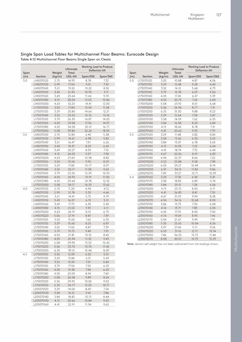
127 Multichannel Kingspan Multibeam
Mul
tich
anne
l
Single Span Load Tables for Multichannel Floor Beams: Eurocode Design Table 4:12 Multichannel Floor Beams Single Span on Cleats
Span (m)
Section
Weight (kg/m)
Ultimate Total
UDL kN
Working Load to Produce Deflection kN
Span/250 Span/3603.0 L145070120 2.75 14.93 8.78 7.32
L145070130 2.99 17.04 9.51 7.92L145070140 3.21 19.22 10.22 8.52L145070150 3.45 21.43 10.93 9.11L145070160 3.69 23.64 11.64 9.70L145070180 4.15 28.04 13.03 10.86L145070200 4.63 32.25 14.41 12.00L175070120 3.02 17.84 13.54 11.28L175070130 3.29 20.80 14.66 12.21L175070140 3.52 23.53 15.76 13.14L175070150 3.79 26.30 16.87 14.05L175070160 4.05 29.08 17.96 14.97L175070180 4.55 34.58 20.12 16.77L175070200 5.08 39.86 22.26 18.55
3.5 L145070120 2.75 12.80 6.45 5.38L145070130 2.99 14.61 6.98 5.82L145070140 3.21 16.47 7.51 6.26L145070150 3.45 18.37 8.03 6.69L145070160 3.69 20.27 8.55 7.12L145070180 4.15 24.03 9.57 7.98L145070200 4.63 27.65 10.58 8.82L175070120 3.02 15.54 9.95 8.29L175070130 3.29 17.83 10.77 8.97L175070140 3.52 20.17 11.58 9.65L175070150 3.79 22.55 12.39 10.33L175070160 4.05 24.92 13.19 11.00L175070180 4.55 29.64 14.78 12.32L175070200 5.08 34.17 16.35 13.62
4.0 L145070120 2.75 11.20 4.94 4.12L145070130 2.99 12.78 5.35 4.46L145070140 3.21 14.41 5.75 4.79L145070150 3.45 16.07 6.15 5.12L145070160 3.69 17.73 6.55 5.45L145070180 4.15 21.02 7.33 6.11L145070200 4.63 24.19 8.10 6.75L145070220 5.06 27.19 8.87 7.39L175070120 3.02 13.60 7.62 6.35L175070130 3.29 15.60 8.25 6.87L175070140 3.52 17.65 8.87 7.39L175070150 3.79 19.73 9.49 7.91L175070160 4.05 21.81 10.10 8.42L175070180 4.55 25.94 11.32 9.43L175070200 5.08 29.90 12.52 10.43L175070220 5.56 33.70 13.70 11.42L175070250 6.35 39.12 15.44 12.87
4.5 L175070120 3.02 12.09 6.02 5.01L175070130 3.29 13.86 6.51 5.43L175070140 3.52 15.69 7.01 5.84L175070150 3.79 17.54 7.50 6.25L175070160 4.05 19.38 7.98 6.65L175070180 4.55 23.05 8.94 7.45L175070200 5.08 26.58 9.89 8.24L175070220 5.56 29.95 10.82 9.02L175070250 6.35 34.77 12.20 10.17L205070120 3.29 14.04 8.69 7.24L205070130 3.58 16.21 9.41 7.84L205070140 3.84 18.42 10.13 8.44L205070150 4.13 20.66 10.84 9.03L205070160 4.41 22.91 11.54 9.62
Span (m)
Section
Weight (kg/m)
Ultimate Total
UDL kN
Working Load to Produce Deflection kN
Span/250 Span/3605.0 L175070120 3.02 10.88 4.87 4.06
L175070130 3.29 12.48 5.28 4.40L175070140 3.52 14.12 5.68 4.73L175070150 3.79 15.78 6.07 5.06L175070160 4.05 17.45 6.47 5.39L175070180 4.55 20.75 7.24 6.04L175070200 5.08 23.92 8.01 6.68L175070220 5.56 26.96 8.77 7.31L175070250 6.35 31.30 9.88 8.23L205070120 3.29 12.64 7.04 5.87L205070130 3.58 14.59 7.62 6.35L205070140 3.84 16.58 8.20 6.84L205070150 4.13 18.60 8.78 7.31L205070160 4.41 20.62 9.35 7.79
5.5 L205070120 3.29 11.48 5.82 4.85L205070130 3.58 13.26 6.30 5.25L205070140 3.84 15.07 6.78 5.65L205070150 4.13 16.90 7.25 6.04L205070160 4.41 18.74 7.72 6.44L205070170 4.67 20.56 8.19 6.83L205070180 4.96 22.37 8.66 7.22L205070200 5.53 25.88 9.58 7.98L205070220 6.05 29.27 10.49 8.74L205070250 6.91 34.13 11.83 9.86L205070270 7.49 37.27 12.71 10.59
6.0 L205070160 3.29 17.18 6.49 5.41L205070170 3.58 18.85 6.89 5.74L205070180 3.84 20.51 7.28 6.06L205070200 4.13 23.72 8.05 6.71L205070220 4.41 26.83 8.81 7.35L205070250 4.67 31.29 9.94 8.28L205070270 4.96 34.16 10.68 8.90L235070130 3.86 13.75 7.30 6.08L235070140 4.14 15.71 7.85 6.54L235070150 4.45 17.70 8.40 7.00L235070160 4.76 19.69 8.95 7.46L235070170 5.04 21.67 9.49 7.91L235070180 5.35 23.63 10.04 8.36L235070200 5.97 27.46 11.11 9.26L235070220 6.53 31.16 12.17 10.14L235070250 7.46 36.53 13.73 11.44L235070270 8.08 40.01 14.75 12.29
Note: section self weight has not been subtracted from the loadings shown.
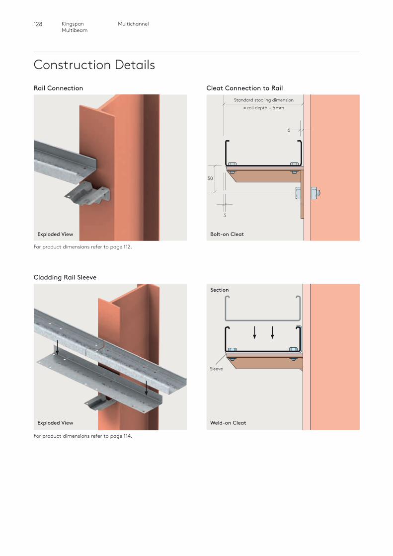
128 MultichannelKingspan Multibeam
Construction DetailsCleat Connection to Rail
Section
Rail Connection
Cladding Rail Sleeve
For product dimensions refer to page 112.
For product dimensions refer to page 114.
Sleeve
Bolt-on CleatExploded View
Weld-on CleatExploded View
6
50
3
Standard stooling dimension
= rail depth + 6mm
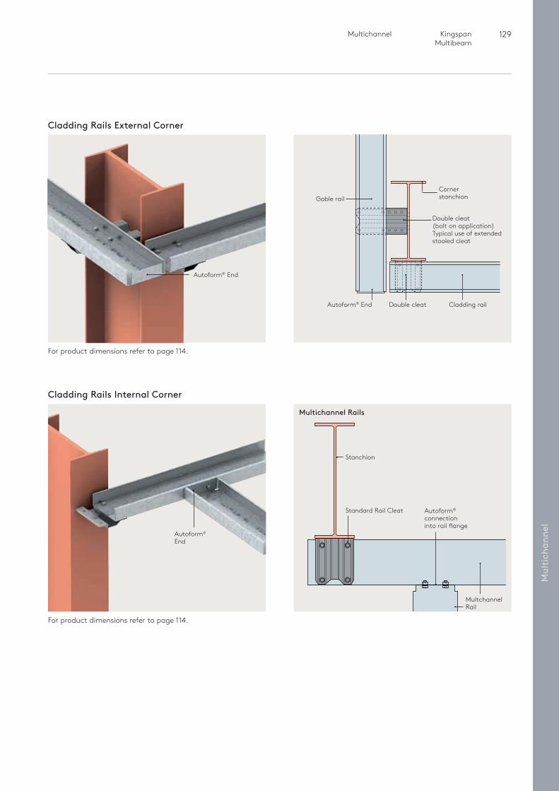
129 Multichannel Kingspan Multibeam
Mul
tich
anne
l
Multichannel Rails
Autoform® connection into rail flange
Stanchion
Standard Rail Cleat
Multchannel Rail
Cladding Rails External Corner
For product dimensions refer to page 114.
Gable rail
Autoform® End
Autoform® End
Double cleat (bolt on application) Typical use of extended stooled cleat
Corner stanchion
Double cleat Cladding rail
Cladding Rails Internal Corner
Autoform® End
For product dimensions refer to page 114.
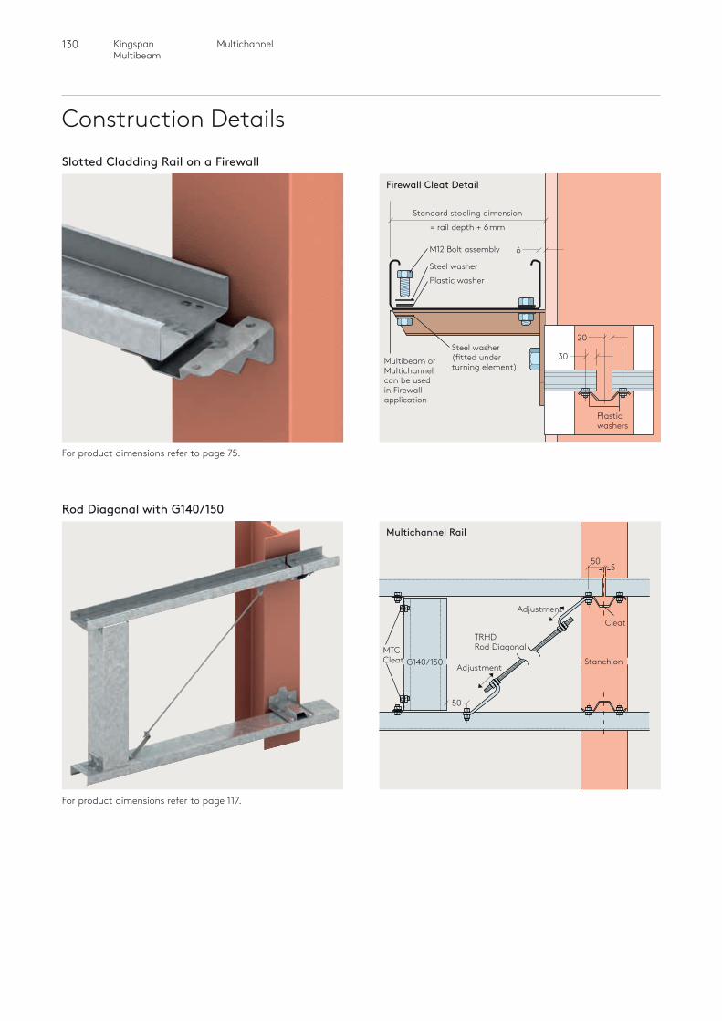
130 MultichannelKingspan Multibeam
Construction DetailsSlotted Cladding Rail on a Firewall
For product dimensions refer to page 75.
Firewall Cleat Detail
6
Standard stooling dimension
= rail depth + 6mm
Multibeam or Multichannel can be used in Firewall application
20
30
Rod Diagonal with G140/150
For product dimensions refer to page 117.
MTCCleat
TRHDRod Diagonal
Adjustment
Adjustment
StanchionG140/150
Multichannel Rail
50
Cleat
550
Plastic washerSteel washer
Steel washer (fitted under turning element)
M12 Bolt assembly
Plastic washers
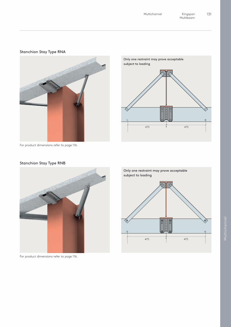
131 Multichannel Kingspan Multibeam
Mul
tich
anne
l
Only one restraint may prove acceptable subject to loading
475 475
Stanchion Stay Type RNA
For product dimensions refer to page 116.
For product dimensions refer to page 116.
Only one restraint may prove acceptable subject to loading
475 475
Stanchion Stay Type RNB
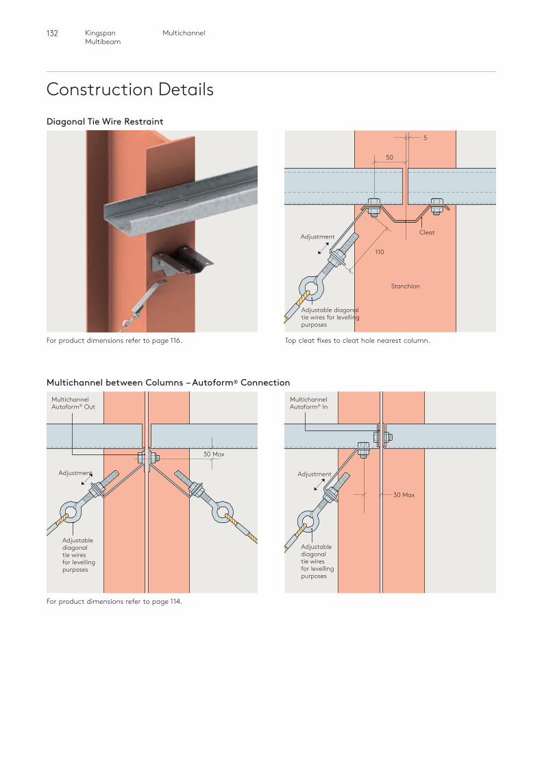
132 MultichannelKingspan Multibeam
Construction DetailsDiagonal Tie Wire Restraint
For product dimensions refer to page 116.
5
50
110
Adjustment
Stanchion
Cleat
Adjustable diagonal tie wires for levelling purposes
Multichannel between Columns – Autoform® Connection
For product dimensions refer to page 114.
Multichannel Autoform® Out
Multichannel Autoform® In
Adjustment
Adjustable diagonal tie wires for levelling purposes
Adjustment
30 Max
30 Max
Adjustable diagonal tie wires for levelling purposes
Top cleat fixes to cleat hole nearest column.
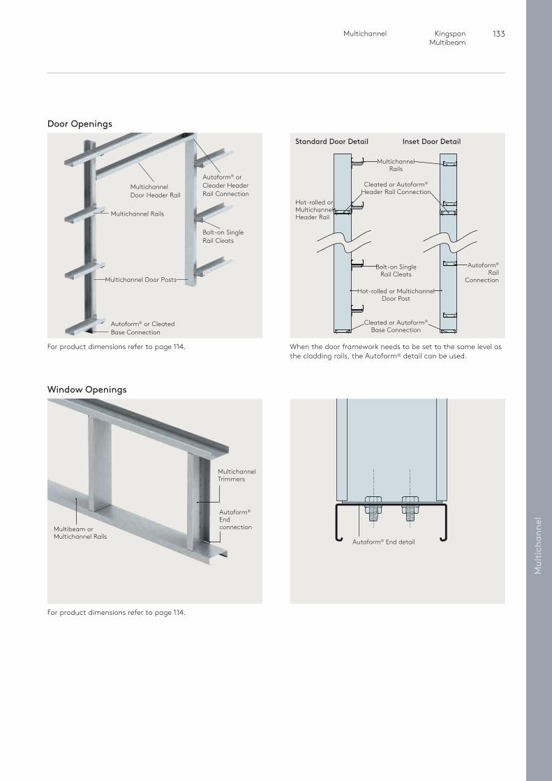
133 Multichannel Kingspan Multibeam
Mul
tich
anne
l
Door Openings
For product dimensions refer to page 114. When the door framework needs to be set to the same level as the cladding rails, the Autoform® detail can be used.
Multichannel Door Header Rail
Autoform® or Cleader Header Rail Connection
Bolt-on Single Rail Cleats
Multichannel Door Posts
Multichannel Rails
Autoform® or Cleated Base Connection
Multichannel Trimmers
Autoform® End connectionMultibeam or
Multichannel Rails
Window Openings
For product dimensions refer to page 114.
Autoform® End detail
Multichannel Rails
Hot-rolled or Multichannel Door Post
Bolt-on Single Rail Cleats
Autoform® Rail
Connection
Hot-rolled or Multichannel Header Rail
Cleated or Autoform® Base Connection
Cleated or Autoform® Header Rail Connection
Standard Door Detail Inset Door Detail
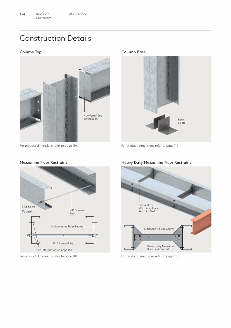
134 MultichannelKingspan Multibeam
Construction DetailsColumn BaseColumn Top
For product dimensions refer to page 114. For product dimensions refer to page 116.
Autoform® End connection Base
cleats
Mezzanine Floor Restraint Heavy Duty Mezzanine Floor Restraint
For product dimensions refer to page 110. For product dimensions refer to page 115.
Mid Span Restraint
Multichannel Floor Beams
M12 Screwed Rod
Hole information on page 138
M12 Screwed Rod
Heavy Duty Mezzanine Floor Restraint SWF
Multichannel Floor Beams
Heavy Duty Mezzanine Floor Restraint SWF
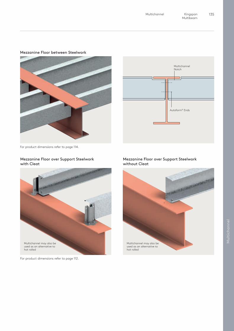
135 Multichannel Kingspan Multibeam
Mul
tich
anne
l
Mezzanine Floor between Steelwork
For product dimensions refer to page 114.
Autoform® Ends
Multichannel Notch
Mezzanine Floor over Support Steelwork with Cleat
For product dimensions refer to page 112.
Multichannel may also be used as an alternative to hot rolled
Mezzanine Floor over Support Steelwork without Cleat
Multichannel may also be used as an alternative to hot rolled
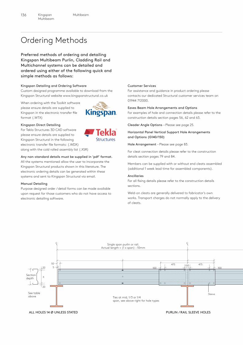
136 MultibeamKingspan Multibeam
Ordering Methods
Kingspan Detailing and Ordering Software Custom designed programme available to download from the Kingspan Structural website www.kingspanstructural.co.uk
When ordering with the Toolkit software please ensure details are supplied to Kingspan in the electronic transfer file format (.WTX)
Kingspan Direct DetailingFor Tekla Structures 3D CAD software please ensure details are supplied to Kingspan Structural in the following electronic transfer file formats: (.WDX) along with the cold
rolled assembly list (.XSR)
Any non-standard details must be supplied in ‘pdf’ format.All the systems mentioned allow the user to incorporate the Kingspan Structural products shown in this literature. The electronic ordering details can be generated within these systems and sent to Kingspan Structural via email.
Manual DetailingPurpose designed order / detail forms can be made available upon request for those customers who do not have access to electronic detailing software.
100= =
Customer ServicesFor assistance and guidance in product ordering please contacts our dedicated Structural customer services team on 01944 712000.
Eaves Beam Hole Arrangements and OptionsFor examples of hole and connection details please refer to the construction details section pages 56, 62 and 63.
Cleader Angle Options – Please see page 25.
Horizontal Panel Vertical Support Hole Arrangements and Options (G140/150)
Hole Arrangement – Please see page 83.
For cleat connection details please refer to the construction details section pages 79 and 84.
Members can be supplied with or without end cleats assembled (additional 1 week lead time for assembled components).
AncillariesFor all fixing details please refer to the construction details sections.
Weld-on cleats are generally delivered to fabricator’s own works. Transport charges do not normally apply to the delivery of cleats.
Preferred methods of ordering and detailing Kingspan Multibeam Purlin, Cladding Rail and Multichannel systems can be detailed and ordered using either of the following quick and simple methods as follows:
50520
X
20
PURLIN / RAIL SLEEVE HOLESALL HOLES 14 Ø UNLESS STATED
Single span purlin or rail.Actual length = (1 x span) – 10mm
Section depth
Ties at mid, 1/3 or 1/4span, see above right for hole types
See tableabove
C L C L
100475 475
100
Sleeve
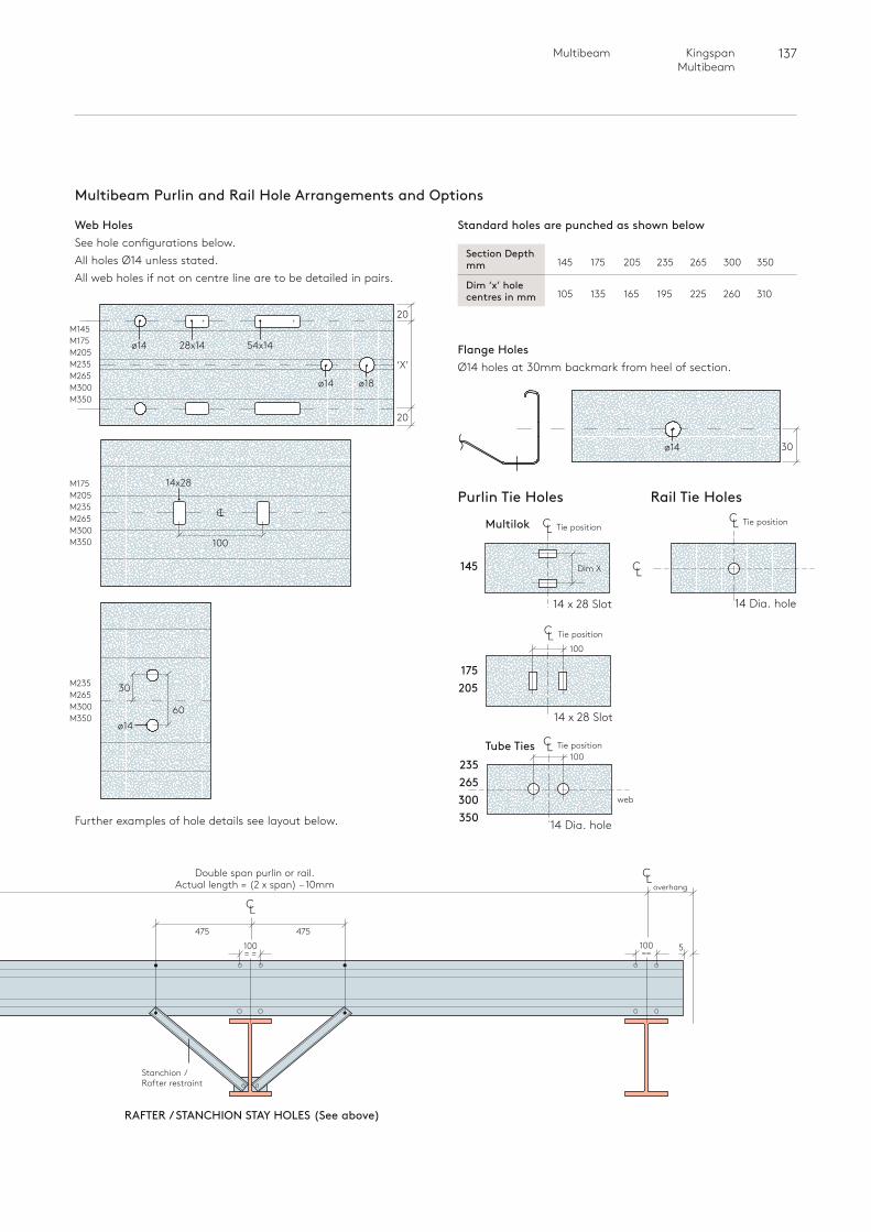
137 Multibeam Kingspan Multibeam
overhang
Multibeam Purlin and Rail Hole Arrangements and Options
Purlin Tie Holes Rail Tie Holes
Section Depth 145 175 205 235 265 300 350
mm
Dim ‘x’ hole 105 135 165 195 225 260 310
centres in mm
Standard holes are punched as shown below
Flange Holes Ø14 holes at 30mm backmark from heel of section.
Web HolesSee hole configurations below. All holes Ø14 unless stated. All web holes if not on centre line are to be detailed in pairs.
C L
100= =
Stanchion / Rafter restraint
475 475
M145M175M205M235M265M300M350
M175M205M235M265M300M350
M235M265M300M350
RAFTER / STANCHION STAY HOLES (See above)
Double span purlin or rail.Actual length = (2 x span) – 10mm
C L
100== 5
Multilok
145
175 205
C L Tie position
C L Tie position
C L Tie position
C L Tie position
C L
web
Dim X
100Tube Ties
14 Dia. hole
14 x 28 Slot
‘X’
20
ø14
ø14 28x14 54x14
ø18
14x28
20
30
100
60
30
CL
ø14
ø14
14 x 28 Slot
14 Dia. hole
100
Further examples of hole details see layout below.
235 265 300 350
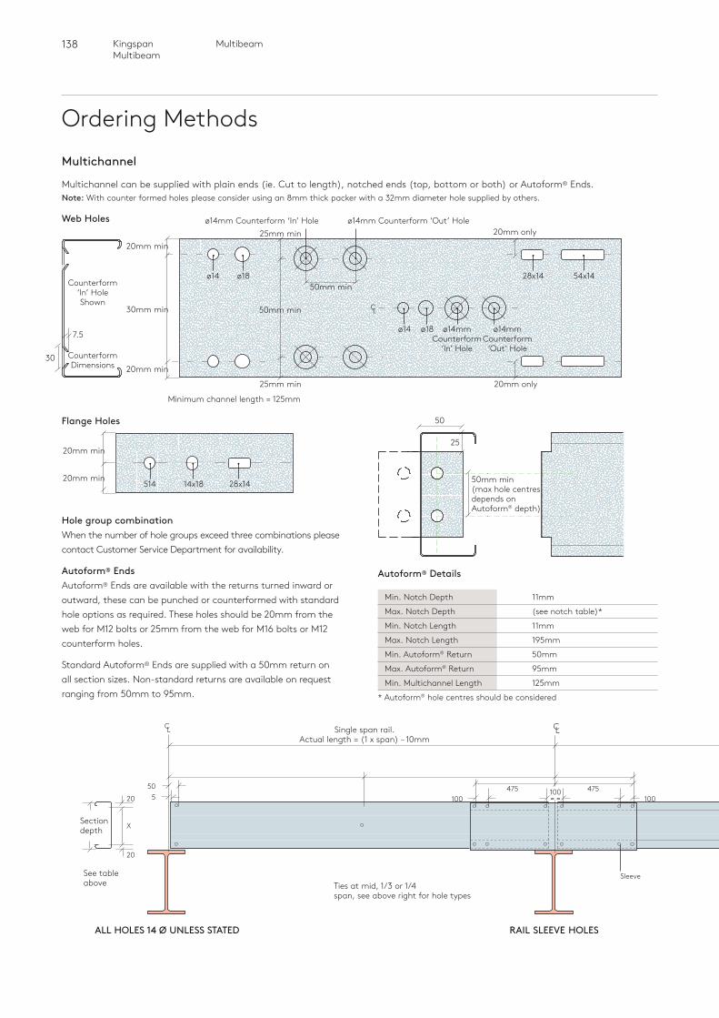
138 MultibeamKingspan Multibeam
Ordering MethodsMultichannel
Multichannel can be supplied with plain ends (ie. Cut to length), notched ends (top, bottom or both) or Autoform® Ends.Note: With counter formed holes please consider using an 8mm thick packer with a 32mm diameter hole supplied by others.
Hole group combinationWhen the number of hole groups exceed three combinations please contact Customer Service Department for availability.
Autoform® EndsAutoform® Ends are available with the returns turned inward or outward, these can be punched or counterformed with standard hole options as required. These holes should be 20mm from the web for M12 bolts or 25mm from the web for M16 bolts or M12 counterform holes.
Standard Autoform® Ends are supplied with a 50mm return on all section sizes. Non-standard returns are available on request ranging from 50mm to 95mm.
100= =
50520
X
20
RAIL SLEEVE HOLESALL HOLES 14 Ø UNLESS STATED
Single span rail.Actual length = (1 x span) – 10mm
Section depth
Ties at mid, 1/3 or 1/4span, see above right for hole types
See tableabove
C L CL
100475 475
100
Sleeve
50mm min (max hole centres depends on Autoform® depth)
25
50Flange Holes
514 14x18 28x14
20mm min
20mm min
Minimum channel length = 125mm
Web Holes
ø14 ø18 28x14 54x14
ø14
30mm min
ø18
ø14mm Counterform ‘In’ Hole ø14mm Counterform ‘Out’ Hole
ø14mm Counterform
‘In’ Hole
Counterform ‘In’ HoleShown
Counterform Dimensions
ø14mm Counterform
‘Out’ Hole
20mm min
20mm min
25mm min 20mm only
25mm min 20mm only
50mm min
50mm min
30
7.5
C L
Autoform® Details
Min. Notch Depth 11mm
Max. Notch Depth (see notch table)*
Min. Notch Length 11mm
Max. Notch Length 195mm
Min. Autoform® Return 50mm
Max. Autoform® Return 95mm
Min. Multichannel Length 125mm
* Autoform® hole centres should be considered
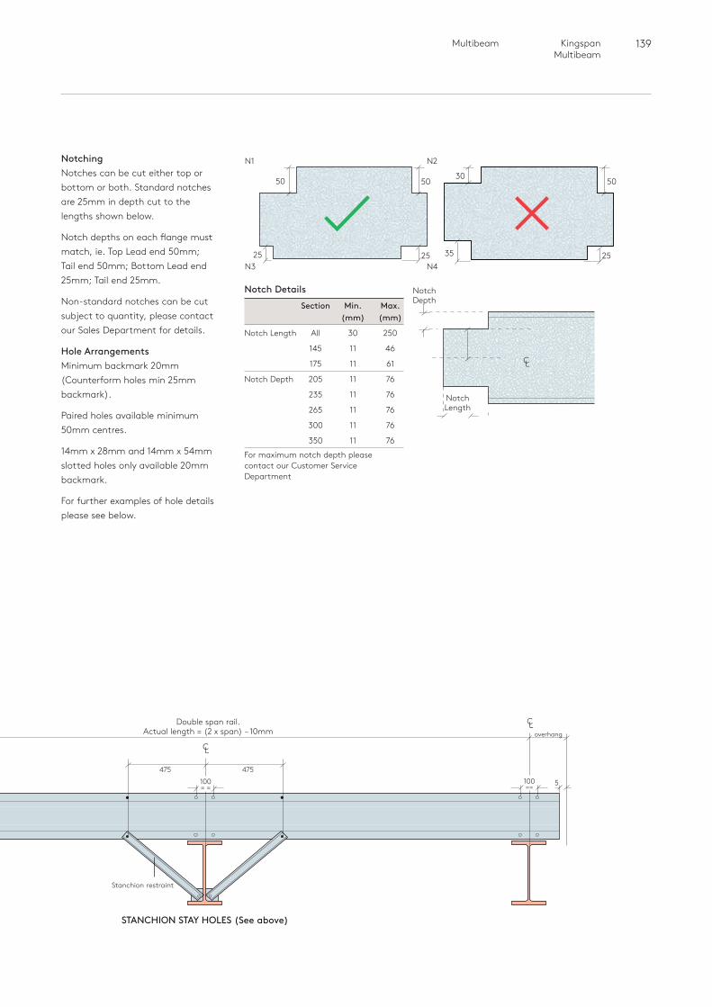
139 Multibeam Kingspan Multibeam
NotchingNotches can be cut either top or bottom or both. Standard notches are 25mm in depth cut to the lengths shown below.
Notch depths on each flange must match, ie. Top Lead end 50mm; Tail end 50mm; Bottom Lead end 25mm; Tail end 25mm.
Non-standard notches can be cut subject to quantity, please contact our Sales Department for details.
Hole ArrangementsMinimum backmark 20mm (Counterform holes min 25mm backmark).
Paired holes available minimum 50mm centres.
14mm x 28mm and 14mm x 54mm slotted holes only available 20mm backmark.
For further examples of hole details please see below.
Section Min. Max. (mm) (mm)
Notch Length All 30 250
145 11 46
175 11 61
Notch Depth 205 11 76
235 11 76
265 11 76
300 11 76
350 11 76
For maximum notch depth please contact our Customer Service Department
N2
N4
5030
2535
N1
N3
5050
2525
overhang
CL
100= =
Stanchion restraint
475 475
STANCHION STAY HOLES (See above)
Double span rail.Actual length = (2 x span) – 10mm
CL
100== 5
Notch Details Notch Depth
CL
Notch Length
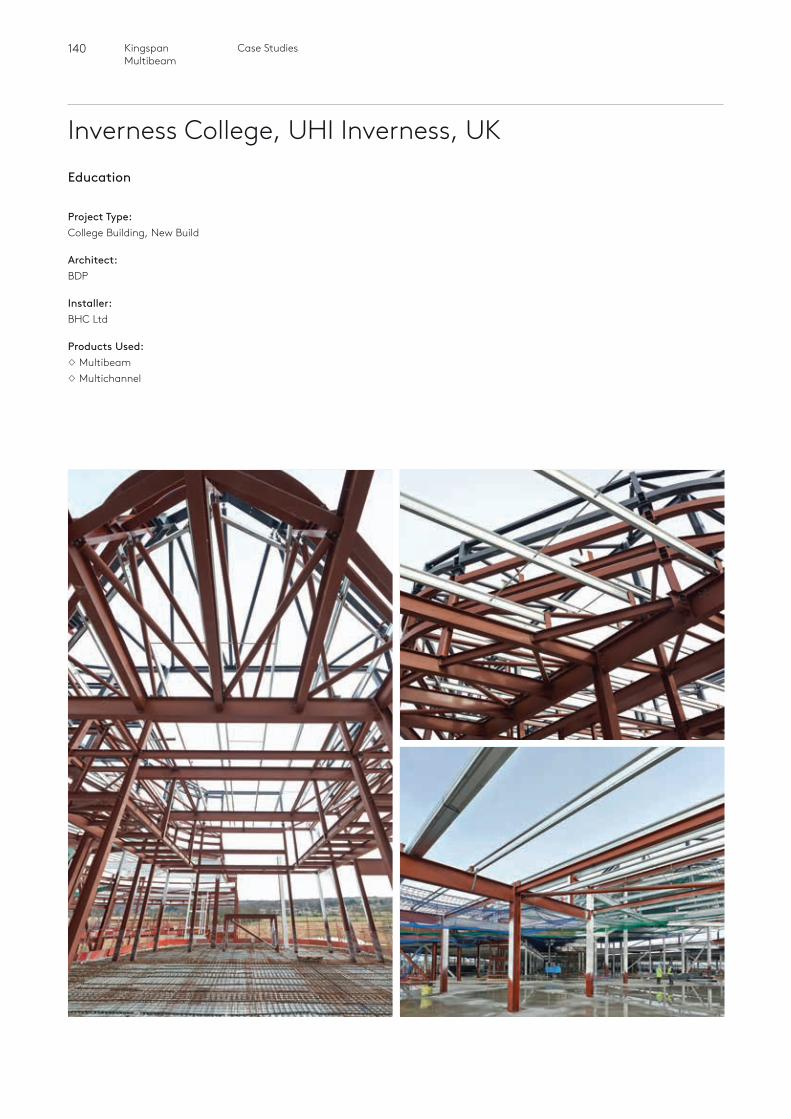
140 Kingspan Multibeam
Inverness College, UHI Inverness, UKEducation
Project Type:College Building, New Build
Architect:BDP
Installer:BHC Ltd
Products Used:MultibeamMultichannel
Case Studies
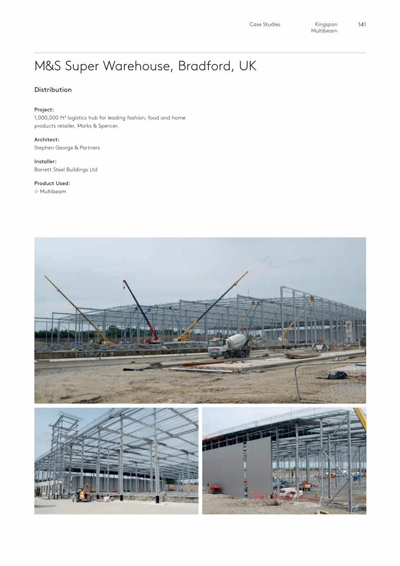
141 Kingspan Multibeam
M&S Super Warehouse, Bradford, UKDistribution
Project:1,000,000 ft2 logistics hub for leading fashion, food and home products retailer, Marks & Spencer.
Architect:Stephen George & Partners
Installer:Barrett Steel Buildings Ltd
Product Used:Multibeam
Case Studies

142 Kingspan Multibeam
Monarch Airlines Hangar,Birmingham, UK
Case Studies
Infrastructure
Project:Aircraft hangar to hold multiple aircraft, enabling Monarch Airlines to repair not just its own fleet, but other planes too if required.
Architect:D5 Architects
Installer:The Monk Bridge Construction Company
Product Used:Multibeam
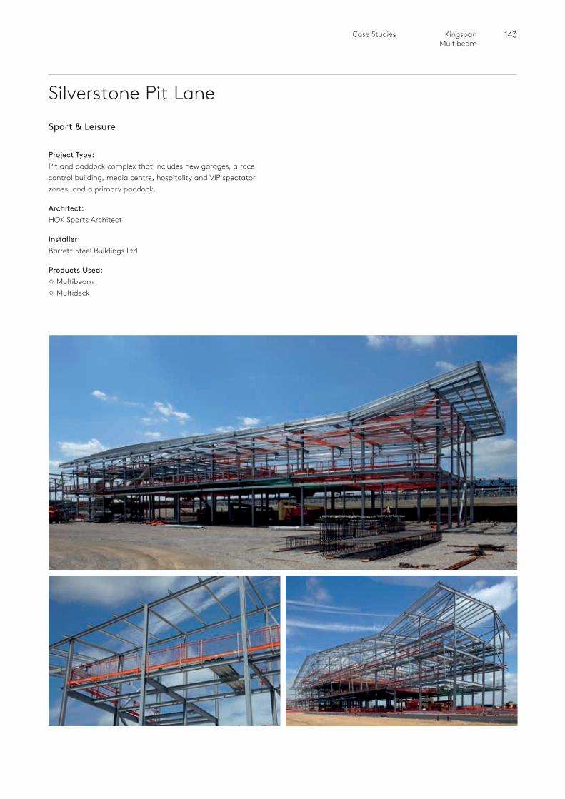
143 Kingspan Multibeam
Silverstone Pit Lane
Case Studies
Sport & Leisure
Project Type:Pit and paddock complex that includes new garages, a race control building, media centre, hospitality and VIP spectator zones, and a primary paddock.
Architect:HOK Sports Architect
Installer:Barrett Steel Buildings Ltd
Products Used:MultibeamMultideck
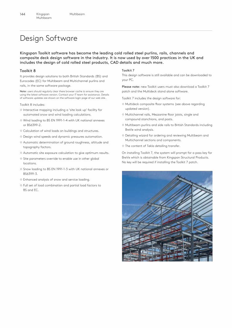
144 Kingspan Multibeam
Multibeam
Design Software
Kingspan Toolkit software has become the leading cold rolled steel purlins, rails, channels and composite deck design software in the industry. It is now used by over 1500 practices in the UK and includes the design of cold rolled steel products, CAD details and much more.
Toolkit 8It provides design solutions to both British Standards (BS) and Eurocodes (EC) for Multibeam and Multichannel purlins and rails, in the same software package.
Note: users should regularly clear there browser cache to ensure they are using the latest software version. Contact your IT team for assistance. Details of software updates are shown on the software login page of our web site..
Toolkit 8 includes:Interactive mapping including a ‘site look up’ facility for
automated snow and wind loading calculations.
Wind loading to BS EN 1991-1-4 with UK national annexes or BS6399-2.
Calculation of wind loads on buildings and structures.
Design wind speeds and dynamic pressures automation.
Automatic determination of ground roughness, altitude and topography factors.
Automatic site exposure calculation to give optimum results.
Site parameters override to enable use in other global locations.
Snow loading to BS EN 1991-1-3 with UK national annexes or BS6399-3.
Enhanced analysis of snow and service loading.
Full set of load combination and partial load factors to BS and EC.
Toolkit 7This design software is still available and can be downloaded to your PC.
Please note: new Toolkit users must also download a Toolkit 7 patch and the Multideck stand alone software.
Toolkit 7 includes the design software for:
Multideck composite floor systems (see above regarding updated version).
Multichannel rails, Mezzanine floor joists, single and compound stanchions, and posts.
Multibeam purlins and side rails to British Standards including BreVe wind analysis.
Detailing wizard for ordering and reviewing Multibeam and Multichannel sections and components.
The content of Tekla detailing transfer.
On installing Toolkit 7, the system will prompt for a pass key for BreVe which is obtainable from Kingspan Structural Products. No key will be required if installing the Toolkit 7 patch.
145 Multibeam Kingspan Multibeam
MultideckWe have issued an update to the Multideck design software, which now includes the new, upgraded Multideck 50-V3 floor decking system (with gauges from 0.85mm to 1.2mm). Existing Toolkit 7 users - please install the new, stand-alone Multideck software to override your existing version. New users - please install both the Multideck and Toolkit 7 design software packages.
Kingspan Structural Products now offers a bespoke design service for Multideck composite steel decking systems, providing Eurocode designs to suit projects in the Republic of Ireland and the UK. To utilise this service please visit http://www.kingspanpanels.co.uk/structural/software/eurocode.
Composite Beam Design SoftwareKingspan Structural Products’ latest design software provides a simple online tool for the design of composite steel beams using it’s Multideck 50, Multideck 60 and Multideck 80 composite steel decking systems to meet the requirements of either BS EN 1994-1: 2004 (Eurocode 4) or BS 5950 Part 3 1990 + A1: 2010, using just one stud per trough in many design cases.
The new software offers design solutions for secondary beams supporting uniformly distributed loads and primary beams supporting point laods at both mid and third points of the span. During the construction stage the secondary beam compression flange is assumed to be fully restrained by the Multideck system, whilst the primary beam compression flange is assumed to be restrained at the relevant load application points.
Kingspan Structural Products - CPDKingspan Structural Products has developed a CPD Seminar which reviews the history of structural materials used in construction with particular focus on the evolution of steel.
The CPD discusses the different components used in steel structure and explores issues which may need to be considered when specifying structural materials. These include designing to Eurocodes or British Standards and the consideration of sustainability and Health & Safety. It also provides a comparison of cold rolled structural materials available in the current market, paying particular attention to different types of purlins.
For further information or to arrange a CPD please contact us on 01944 712000 or email [email protected]
146 MultibeamKingspan Multibeam
IndexA Angle cleats 84,116Anti-sag tie requirements Purlins 12Anti-sag tie requirements Rails 71Apex ties 23,51Autoform® Multichannel 103,114,132
B Base cleats Multichannel 116, 134Bottom strut bracket 84,98Boundary Wall 62,63Brickwork restraint 109
C Cantilevers 45,46Case Studies 140-143Certification 5Clamp Plates 23,82,115Cleader Angles 25Cleats (see also Multicleats) 19,20,21,78,79,80,111,112,113Columns 134Compound Multichannels 109Corners 95,129Customer Service 136
DDesign & Ordering Hole Arrangements - Multibeam 136,137
- Multichannel 138,139 Overview 134 Software 144Diagonal Tie Wires 15,25,51,71,98,83, 116,132Door Openings 108,133
EEaves Beam Dimensions & References 56 Load Charts 60 Material Specification 54 Overview 54 Range 54 Restraint Systems 55 Section Properties 59 External Gutters 62,63,64
FFirewall 74,75Flange Variations 56Flat Roofs 17,48Floor Beams Mezzanine Floors 109,134,135
GGable Posts 109,134
HHole Arrangements - Multibeam 136,137
- Multichannel 138,139Horizontal Cladding 72,73,106,107Horizontal Panel Vertical Support 83,96,117,130
LLoad Tables
Eaves Beam 60
Multichannel Brickwork Restraints - Single 119,120,121 Brickwork Restraints - double 121,122 Double Span - Vertical Cladding 123
- Horizontal Cladding 124,125 Floor Beams: - Single span between steel 126
- Single span with cleats 127
Purlins Double Span 29,30,31,32,33 Double Span Continuous System 34,35,36,37,38 Single Span Continuous System 39,40,41,42,43 Tiled Roofs 33
Cladding Rails Double Span - Vertical Cladding 86,87,88,89
- Horizontal Cladding 90,91,92
MMaterial Specification 10,54,68,102Mezzanine Floors 109,134,135MTC Cleats (also see Angle Cleats) 84,116Multibracket 25,84,117MultichannelApplications Parapets 108 Door & Window Openings 108 Mezzanine Floors 109 Brickwork Restraints 109 Gable Posts 109 General Engineering 109Autoforms® 103,114Load Tables Brickwork Restraints 119,120,121,122 Double Span - Vertical Cladding 123 - Horizontal Cladding 124,125 Floor Beams - Single Span between Steel 126 - Single Span on cleats 127 Material Specification 102
147 Multibeam Kingspan Multibeam
Notches 103,114Overview 102Range 102Restraints - Vertically Laid Cladding 104Restraints - Horizontally Laid Cladding 106,107Section Properties 118Multicleats (also see cleats) 19,20,21,78,79,80,111,112,113Multilok Ties 23,49
NNotches 103,114
OOpenings 133Order Forms See separate handbook ref: P228
P Parapet 65,108 Products Overview 6,7
Purlins Anti Sag Requirements 12 Applications 10 Dimensions & References 18 Load Tables Double Span 29,30,31,32,33 Double Span Continuous System 4,35,36,37,38 Single Span Continuous System 39,40,41,42,43 Tiled Roofs 33 Material Specification 10 Overview 10 Range 10 Restraints Built Up - Membrane Flat Roofs 17 - Roofing 15 - Standing Seam 17 Clip Fix 15 Downslope Ties (through-fix) 15 Flat Roofs 17 Insulated Panels 15 Low Pitch Roof 17 Rooflights 16 Secret & Clip Fix 15 Secret-Fix Insulated Panels 15 Through-fix Roofing 15 Tiled Roof 16 Section Properties 28 Spanning Systems 11 Tie Arrangements 13
RRafter Stays 24,47Rafter Stays Capacities 122
Restraints Firewall 74,75 Horizontally Laid Cladding 72,73 Overview 68 Vertically Laid Cladding 71 Section Properties 85 Spanning Systems 69 Diagonal Tie Wire 98 Firewall 96 Rafter stays 97 Rail Connection 94 Rod Diagonal with G140/150 96 Sleeves 94 Tube Strut Arrangement 98
Rod Diagonals 25,84,117
Roof cladding types 14
SSCILGA accreditation 5
Section PropertiesPurlins 28Eaves Beam 59Cladding Rails 85Multichannel 118Sleeves 11,45,22,81,94,114Stanchion Stays 83,116Stubs 83,117Stanchion Stays Capacities 122
TTiled Roofs 16,50
Tube Struts 13,23,49,82,98,115
VVertical Cladding 71,104
WWindow openings 108,133
Inde
x
04/2018
UKKingspan Limited Sherburn, Malton North Yorkshire YO17 8PQT: +44 (0) 1944 712000 F: +44 (0) 1944 710830www.kingspanpanels.co.uk/structural
IrelandKingspan Limited Carrickmacross Road Kingscourt, Co.Cavan T: +353 (0) 42 969 8500
For the product offering in other markets please contact your local sales representative or visit www.kingspanpanels.com
Care has been taken to ensure that the contents of this publication are accurate, but Kingspan Limited and its subsidiary companies do not accept responsibility for errors or for information that is found to be misleading. Suggestions for, or description of, the end use or application of products or methods of working are for information only and Kingspan Limited and its subsidiaries accept no liability in respect thereof.
Recommended