24.04.2020 Bedienungsanleitung LMC Page 1 of 28
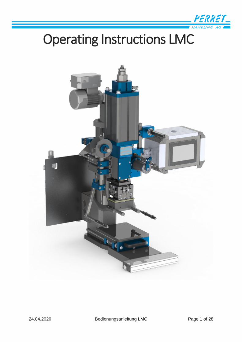
Operating Instructions LMC
24.04.2020 Bedienungsanleitung LMC Page 2 of 28
Table of contents History of the versions ........................................................................................................................................... 3
Control system ........................................................................................................................................................ 4
Switch on the machine ....................................................................................................................................... 4
Automatic operation ..................................................................................... Fehler! Textmarke nicht definiert.
Display information in automatic mode .................................................. Fehler! Textmarke nicht definiert.
Display information in automatic mode in case of error ............................................................................. 6
Manual operation .............................................................................................................................................. 7
Display information in manual mode ........................................................................................................... 7
Height adjustment embossing head ............................................................................................................. 8
Settings Selection ............................................................................................................................................... 9
Input of numerical values .............................................................................................................................. 9
Input limit ...................................................................................................................................................... 9
Display information during setting ............................................................................................................. 10
Settings ............................................................................................................................................................. 11
Settings embossing cylinder ........................................................................................................................ 11
Heating settings ........................................................................................................................................... 12
Film transport settings ................................................................................................................................ 13
Sliding table settings .................................................................................................................................... 14
Settings Counter .......................................................................................................................................... 15
Language setting .......................................................................................................................................... 16
System settings ................................................................................................................................................ 17
software update ................................................................................................................................................... 18
Preparation ...................................................................................................................................................... 18
Installing the software on the controller ........................................................................................................ 18
Machine ................................................................................................................................................................ 19
Foil run .............................................................................................................................................................. 19
5-axis head ....................................................................................................................................................... 20
Settings embossing cylinder ............................................................................................................................ 21
Embossing force diagram ............................................................................................................................ 21
Cylinder stop ................................................................................................................................................ 22
Setting the lifting speed of the embossing cylinder ................................................................................... 23
Adjustment cylinder film transport ................................................................................................................. 24
Coupling height adjustment Embossing head ................................................................................................. 25
Release jammed lifting spindle ................................................................................................................... 25
Coupling unwinding side .................................................................................................................................. 26
Data sheet safety coupling: ............................................................................................................................. 27
24.04.2020 Bedienungsanleitung LMC Page 3 of 28
History of the versions
File name: Operation_PE10_V1_German.docx
Version Author Date Reason for change / Remarks
1 RH 25.02.20 Newly created
3 GP 20.03.20 Translation from German
24.04.2020 Bedienungsanleitung LMC Page 4 of 28
Control system
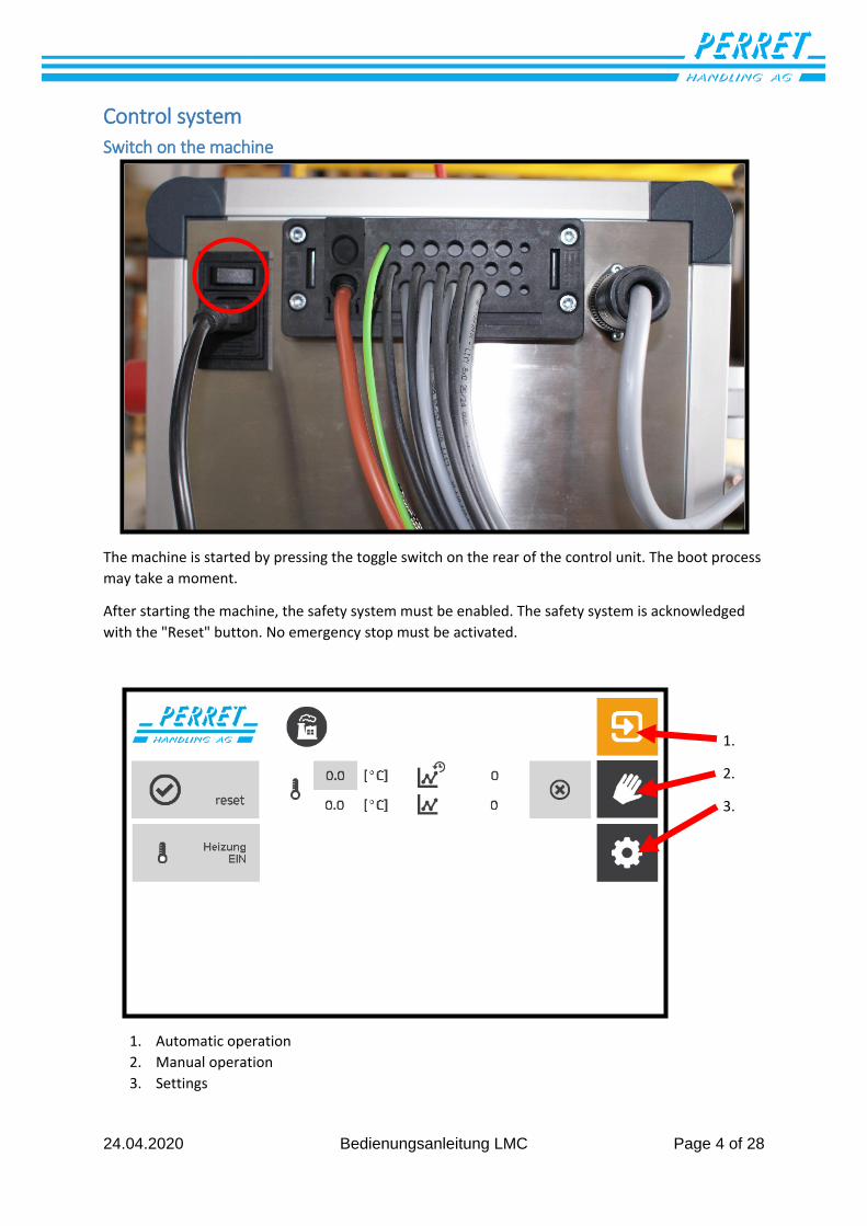
Switch on the machine
The machine is started by pressing the toggle switch on the rear of the control unit. The boot process
may take a moment.
After starting the machine, the safety system must be enabled. The safety system is acknowledged
with the "Reset" button. No emergency stop must be activated.
1. Automatic operation
2. Manual operation
3. Settings
1.
2.
3.
24.04.2020 Bedienungsanleitung LMC Page 5 of 28
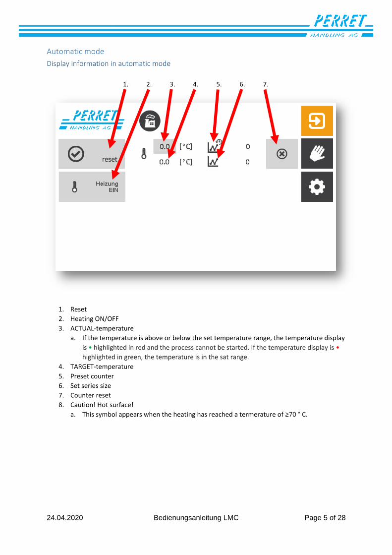
Automatic mode
Display information in automatic mode
1. Reset
2. Heating ON/OFF
3. ACTUAL-temperature
a. If the temperature is above or below the set temperature range, the temperature display
is • highlighted in red and the process cannot be started. If the temperature display is •
highlighted in green, the temperature is in the sat range.
4. TARGET-temperature
5. Preset counter
6. Set series size
7. Counter reset
8. Caution! Hot surface!
a. This symbol appears when the heating has reached a termerature of ≥70 ° C.
1. 2. 3. 4. 5. 6. 7.
24.04.2020 Bedienungsanleitung LMC Page 6 of 28
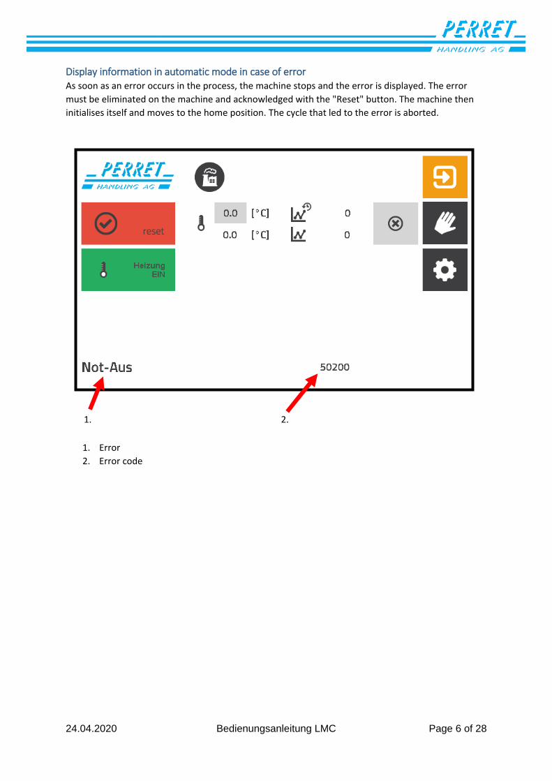
Display information in automatic mode in case of error As soon as an error occurs in the process, the machine stops and the error is displayed. The error
must be eliminated on the machine and acknowledged with the "Reset" button. The machine then
initialises itself and moves to the home position. The cycle that led to the error is aborted.
1. Error
2. Error code
1. 2.
24.04.2020 Bedienungsanleitung LMC Page 7 of 28
Manual operation
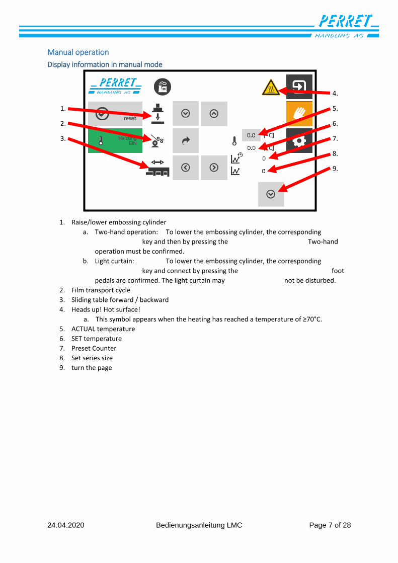
Display information in manual mode
1. Raise/lower embossing cylinder
a. Two-hand operation: To lower the embossing cylinder, the corresponding
key and then by pressing the Two-hand
operation must be confirmed.
b. Light curtain: To lower the embossing cylinder, the corresponding
key and connect by pressing the foot
pedals are confirmed. The light curtain may not be disturbed.
2. Film transport cycle
3. Sliding table forward / backward
4. Heads up! Hot surface!
a. This symbol appears when the heating has reached a temperature of ≥70°C.
5. ACTUAL temperature
6. SET temperature
7. Preset Counter
8. Set series size
9. turn the page
1.
2.
3.
4.
5.
6.
7.
8.
9.
24.04.2020 Bedienungsanleitung LMC Page 8 of 28
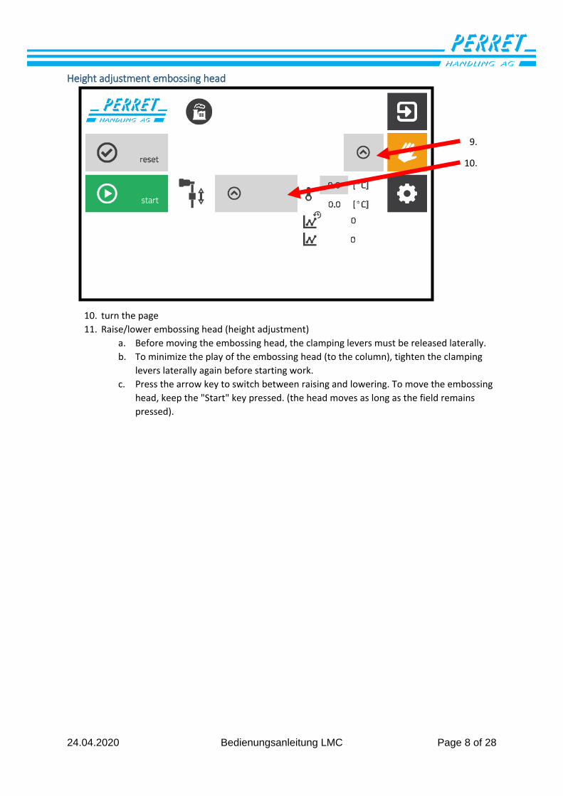
Height adjustment embossing head
10. turn the page
11. Raise/lower embossing head (height adjustment)
a. Before moving the embossing head, the clamping levers must be released laterally.
b. To minimize the play of the embossing head (to the column), tighten the clamping
levers laterally again before starting work.
c. Press the arrow key to switch between raising and lowering. To move the embossing
head, keep the "Start" key pressed. (the head moves as long as the field remains
pressed).
9.
10.
24.04.2020 Bedienungsanleitung LMC Page 9 of 28
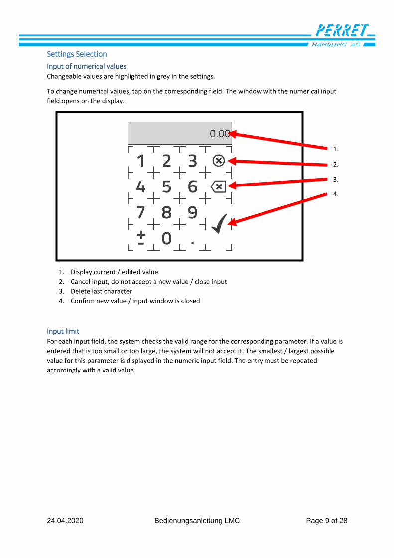
Settings Selection
Input of numerical values Changeable values are highlighted in grey in the settings.
To change numerical values, tap on the corresponding field. The window with the numerical input
field opens on the display.
1. Display current / edited value
2. Cancel input, do not accept a new value / close input
3. Delete last character
4. Confirm new value / input window is closed
Input limit For each input field, the system checks the valid range for the corresponding parameter. If a value is
entered that is too small or too large, the system will not accept it. The smallest / largest possible
value for this parameter is displayed in the numeric input field. The entry must be repeated
accordingly with a valid value.
1.
2.
3.
4.
24.04.2020 Bedienungsanleitung LMC Page 10 of 28
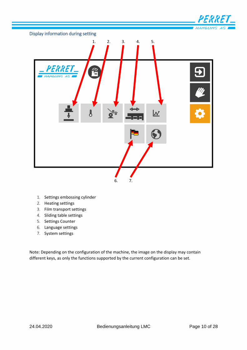
Display information during setting
1. Settings embossing cylinder
2. Heating settings
3. Film transport settings
4. Sliding table settings
5. Settings Counter
6. Language settings
7. System settings
Note: Depending on the configuration of the machine, the image on the display may contain
different keys, as only the functions supported by the current configuration can be set.
1. 2. 3. 4. 5.
6. 7.
24.04.2020 Bedienungsanleitung LMC Page 11 of 28
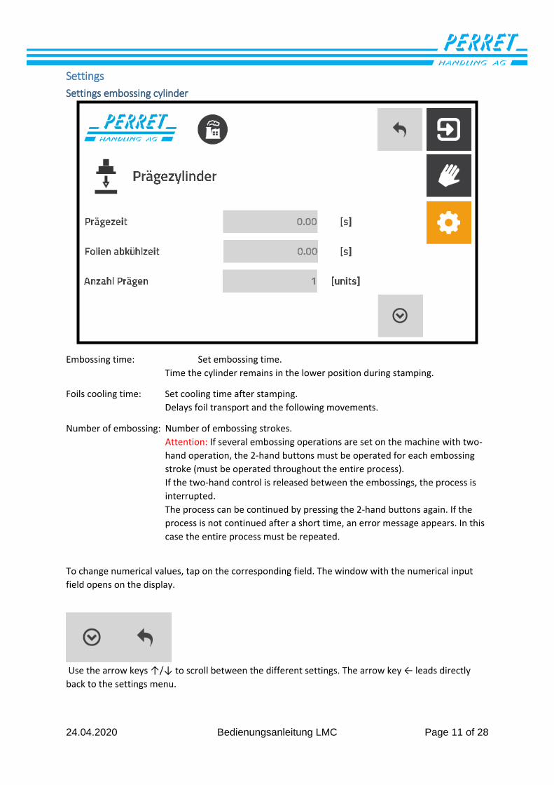
Settings
Settings embossing cylinder
Embossing time: Set embossing time.
Time the cylinder remains in the lower position during stamping.
Foils cooling time: Set cooling time after stamping.
Delays foil transport and the following movements.
Number of embossing: Number of embossing strokes.
Attention: If several embossing operations are set on the machine with two-
hand operation, the 2-hand buttons must be operated for each embossing
stroke (must be operated throughout the entire process).
If the two-hand control is released between the embossings, the process is
interrupted.
The process can be continued by pressing the 2-hand buttons again. If the
process is not continued after a short time, an error message appears. In this
case the entire process must be repeated.
To change numerical values, tap on the corresponding field. The window with the numerical input
field opens on the display.
Use the arrow keys ↑/↓ to scroll between the different settings. The arrow key ← leads directly
back to the settings menu.
24.04.2020 Bedienungsanleitung LMC Page 12 of 28
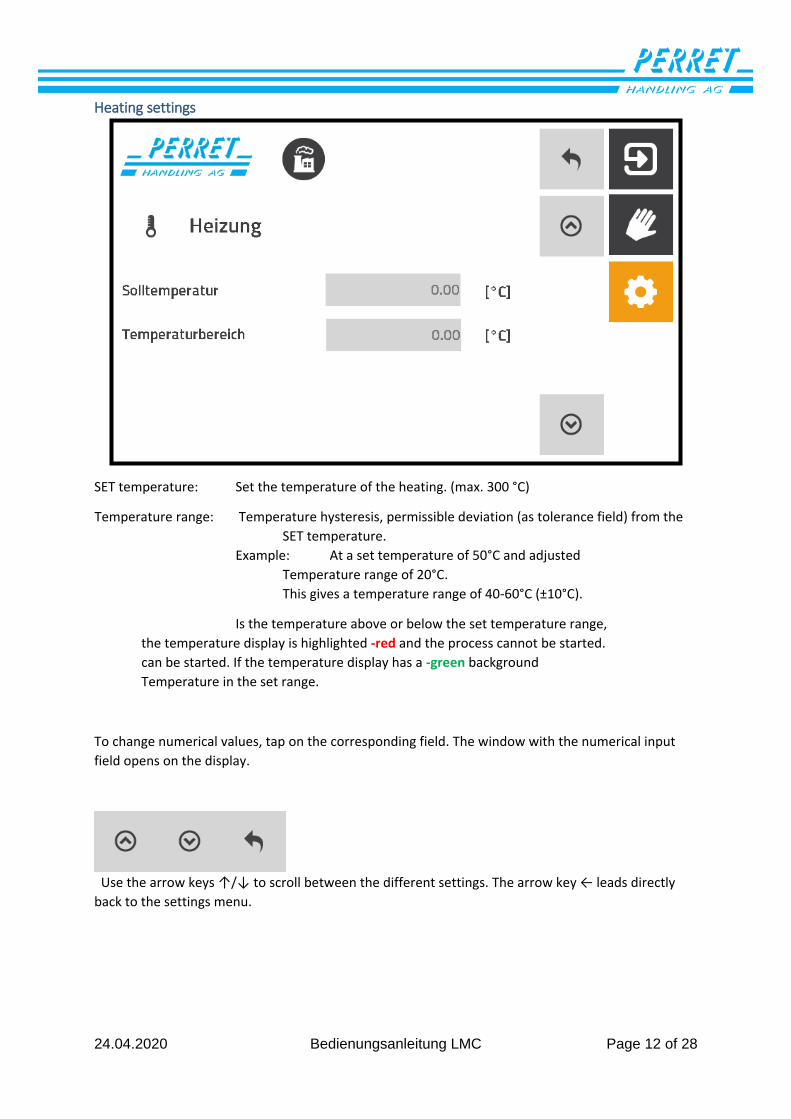
Heating settings
SET temperature: Set the temperature of the heating. (max. 300 °C)
Temperature range: Temperature hysteresis, permissible deviation (as tolerance field) from the
SET temperature.
Example: At a set temperature of 50°C and adjusted
Temperature range of 20°C.
This gives a temperature range of 40-60°C (±10°C).
Is the temperature above or below the set temperature range,
the temperature display is highlighted -red and the process cannot be started.
can be started. If the temperature display has a -green background
Temperature in the set range.
To change numerical values, tap on the corresponding field. The window with the numerical input
field opens on the display.
Use the arrow keys ↑/↓ to scroll between the different settings. The arrow key ← leads directly
back to the settings menu.
24.04.2020 Bedienungsanleitung LMC Page 13 of 28
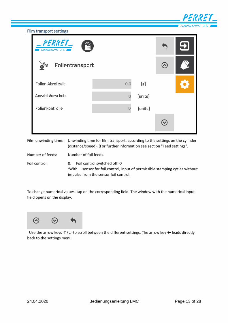
Film transport settings
Film unwinding time: Unwinding time for film transport, according to the settings on the cylinder
(distance/speed). (For further information see section "Feed settings".
Number of feeds: Number of foil feeds.
Foil control: 0: Foil control switched off>0
:With sensor for foil control, input of permissible stamping cycles without
impulse from the sensor foil control.
To change numerical values, tap on the corresponding field. The window with the numerical input
field opens on the display.
Use the arrow keys ↑/↓ to scroll between the different settings. The arrow key ← leads directly
back to the settings menu.
24.04.2020 Bedienungsanleitung LMC Page 14 of 28
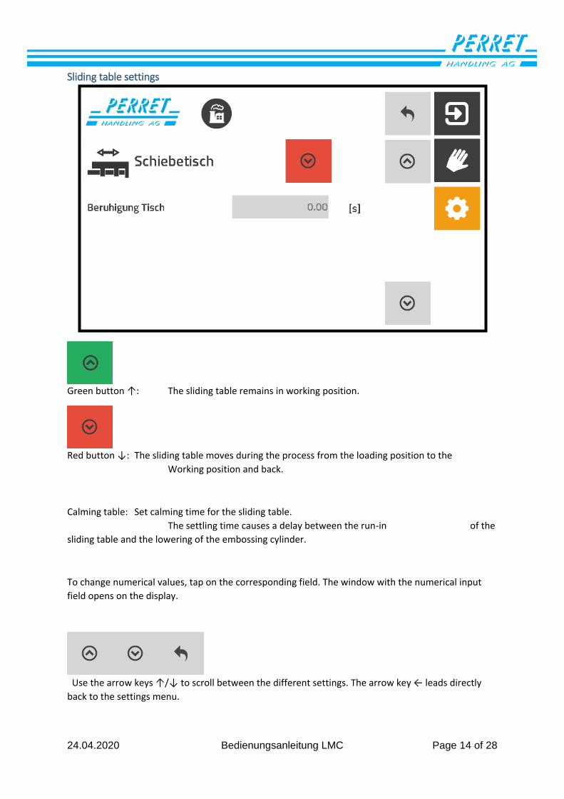
Sliding table settings
Green button ↑: The sliding table remains in working position.
Red button ↓: The sliding table moves during the process from the loading position to the
Working position and back.
Calming table: Set calming time for the sliding table.
The settling time causes a delay between the run-in of the
sliding table and the lowering of the embossing cylinder.
To change numerical values, tap on the corresponding field. The window with the numerical input
field opens on the display.
Use the arrow keys ↑/↓ to scroll between the different settings. The arrow key ← leads directly
back to the settings menu.
24.04.2020 Bedienungsanleitung LMC Page 15 of 28
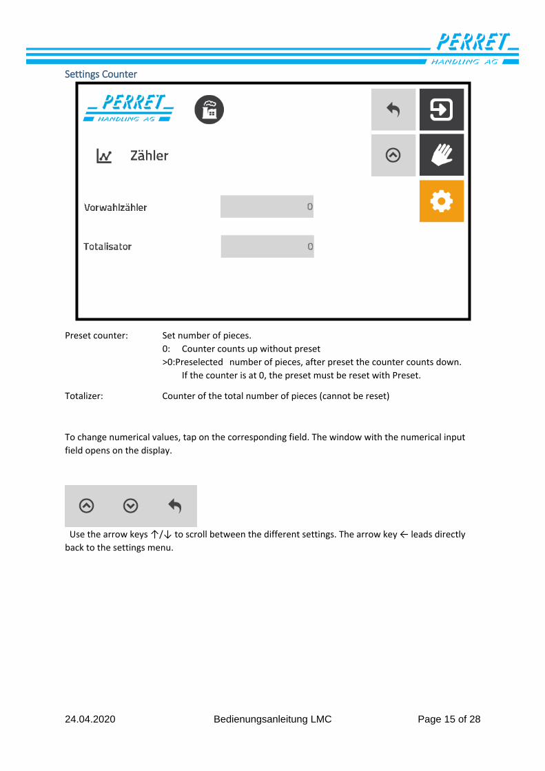
Settings Counter
Preset counter: Set number of pieces.
0: Counter counts up without preset
>0:Preselected number of pieces, after preset the counter counts down.
If the counter is at 0, the preset must be reset with Preset.
Totalizer: Counter of the total number of pieces (cannot be reset)
To change numerical values, tap on the corresponding field. The window with the numerical input
field opens on the display.
Use the arrow keys ↑/↓ to scroll between the different settings. The arrow key ← leads directly
back to the settings menu.
24.04.2020 Bedienungsanleitung LMC Page 16 of 28
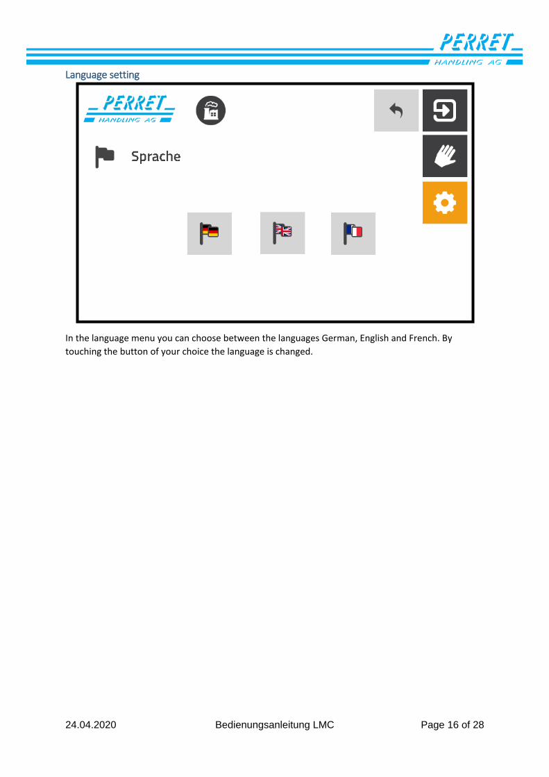
Language setting
In the language menu you can choose between the languages German, English and French. By
touching the button of your choice the language is changed.
24.04.2020 Bedienungsanleitung LMC Page 17 of 28
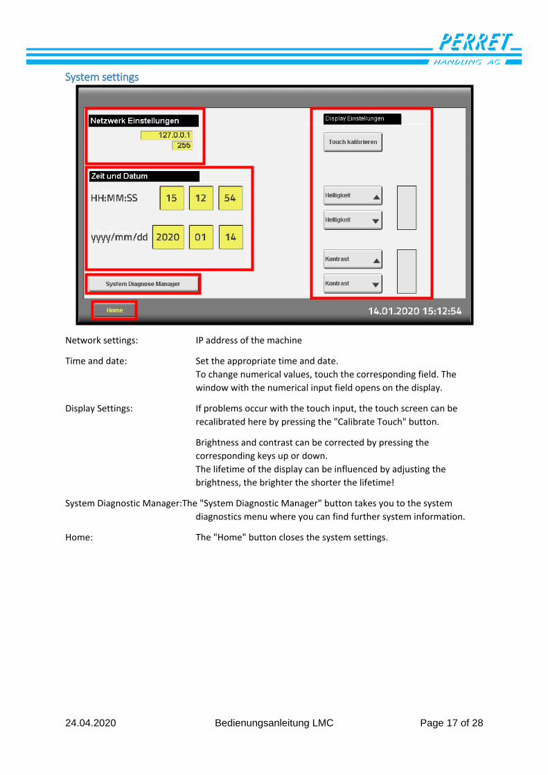
System settings
Network settings: IP address of the machine
Time and date: Set the appropriate time and date.
To change numerical values, touch the corresponding field. The
window with the numerical input field opens on the display.
Display Settings: If problems occur with the touch input, the touch screen can be
recalibrated here by pressing the "Calibrate Touch" button.
Brightness and contrast can be corrected by pressing the
corresponding keys up or down.
The lifetime of the display can be influenced by adjusting the
brightness, the brighter the shorter the lifetime!
System Diagnostic Manager:The "System Diagnostic Manager" button takes you to the system
diagnostics menu where you can find further system information.
Home: The "Home" button closes the system settings.
24.04.2020 Bedienungsanleitung LMC Page 18 of 28
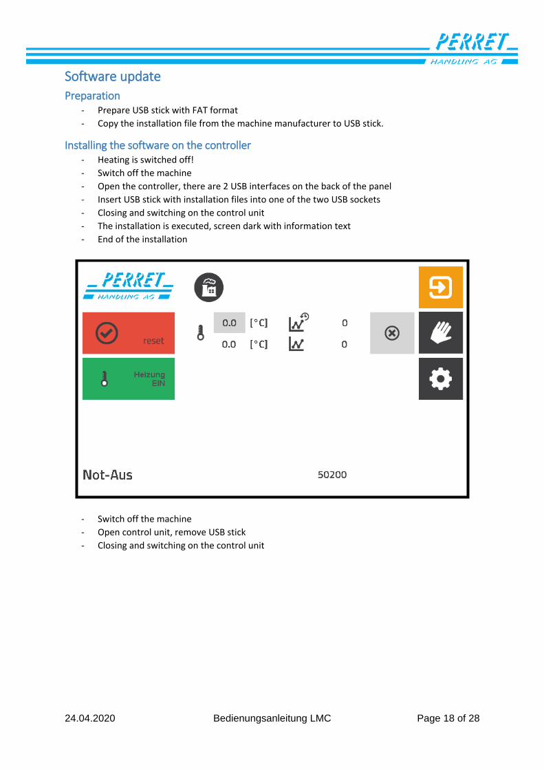
Software update
Preparation - Prepare USB stick with FAT format
- Copy the installation file from the machine manufacturer to USB stick.
Installing the software on the controller - Heating is switched off!
- Switch off the machine
- Open the controller, there are 2 USB interfaces on the back of the panel
- Insert USB stick with installation files into one of the two USB sockets
- Closing and switching on the control unit
- The installation is executed, screen dark with information text
- End of the installation
- Switch off the machine
- Open control unit, remove USB stick
- Closing and switching on the control unit
24.04.2020 Bedienungsanleitung LMC Page 19 of 28
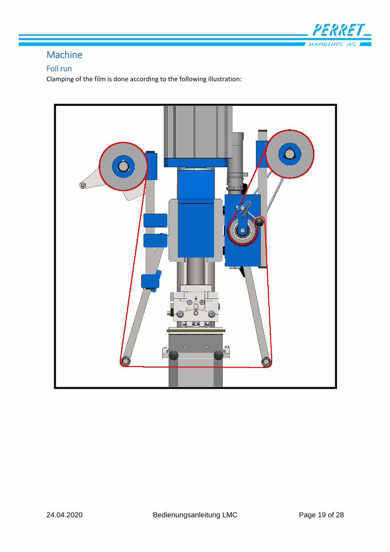
Machine
Foil run Clamping of the film is done according to the following illustration:
24.04.2020 Bedienungsanleitung LMC Page 20 of 28
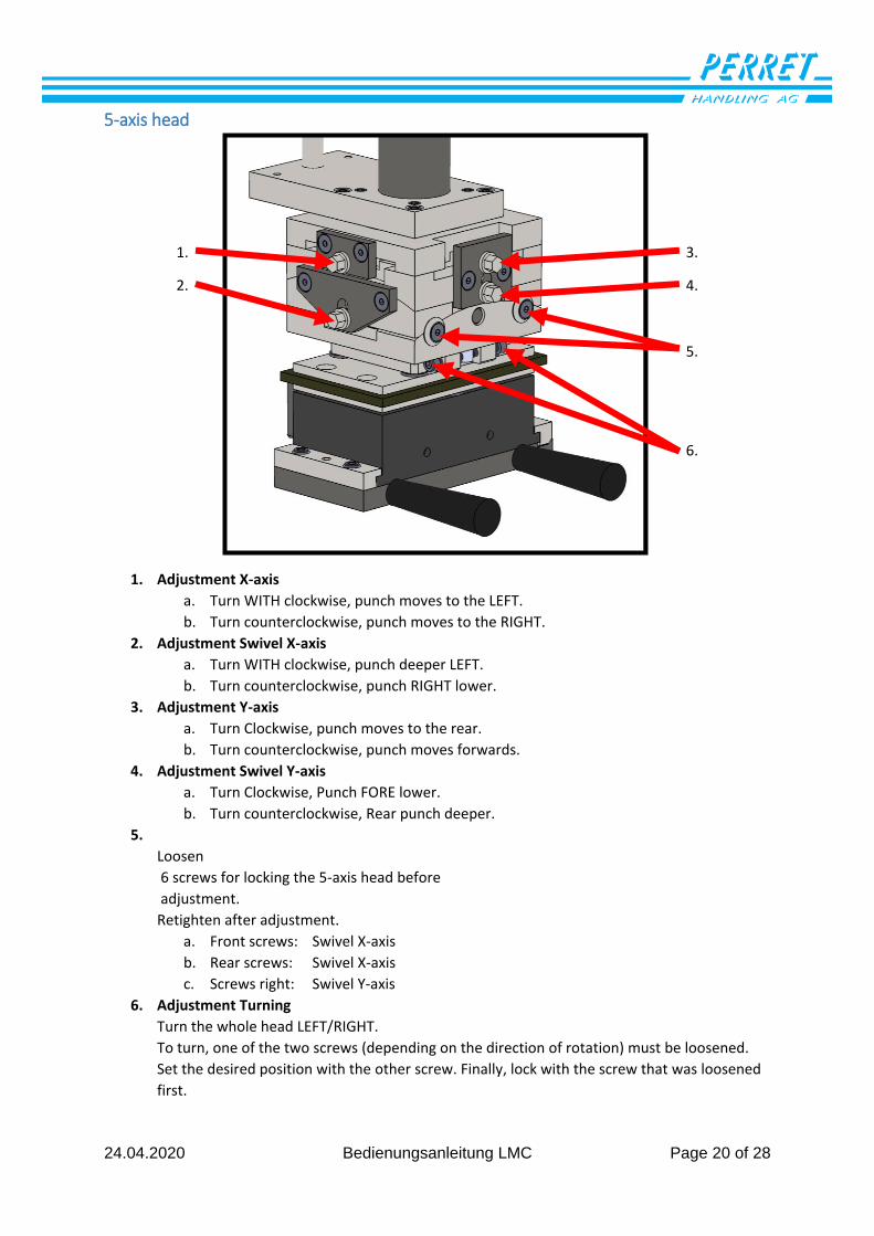
5-axis head
1. Adjustment X-axis
a. Turn WITH clockwise, punch moves to the LEFT.
b. Turn counterclockwise, punch moves to the RIGHT.
2. Adjustment Swivel X-axis
a. Turn WITH clockwise, punch deeper LEFT.
b. Turn counterclockwise, punch RIGHT lower.
3. Adjustment Y-axis
a. Turn Clockwise, punch moves to the rear.
b. Turn counterclockwise, punch moves forwards.
4. Adjustment Swivel Y-axis
a. Turn Clockwise, Punch FORE lower.
b. Turn counterclockwise, Rear punch deeper.
5.
Loosen
6 screws for locking the 5-axis head before
adjustment.
Retighten after adjustment.
a. Front screws: Swivel X-axis
b. Rear screws: Swivel X-axis
c. Screws right: Swivel Y-axis
6. Adjustment Turning
Turn the whole head LEFT/RIGHT.
To turn, one of the two screws (depending on the direction of rotation) must be loosened.
Set the desired position with the other screw. Finally, lock with the screw that was loosened
first.
3.
4.
5.
6.
1.
2.

24.04.2020 Bedienungsanleitung LMC Page 21 of 28
Settings embossing cylinder
Embossing force diagram
0
1000
2000
3000
4000
5000
6000
7000
0 1 2 3 4 5 6 7
forc
e in
new
ton
s
Pressure in bar
LMC 650
0
2000
4000
6000
8000
10000
12000
14000
0 1 2 3 4 5 6 7
forc
e in
new
ton
s
Pressure in bar
LMC 1300
24.04.2020 Bedienungsanleitung LMC Page 22 of 28
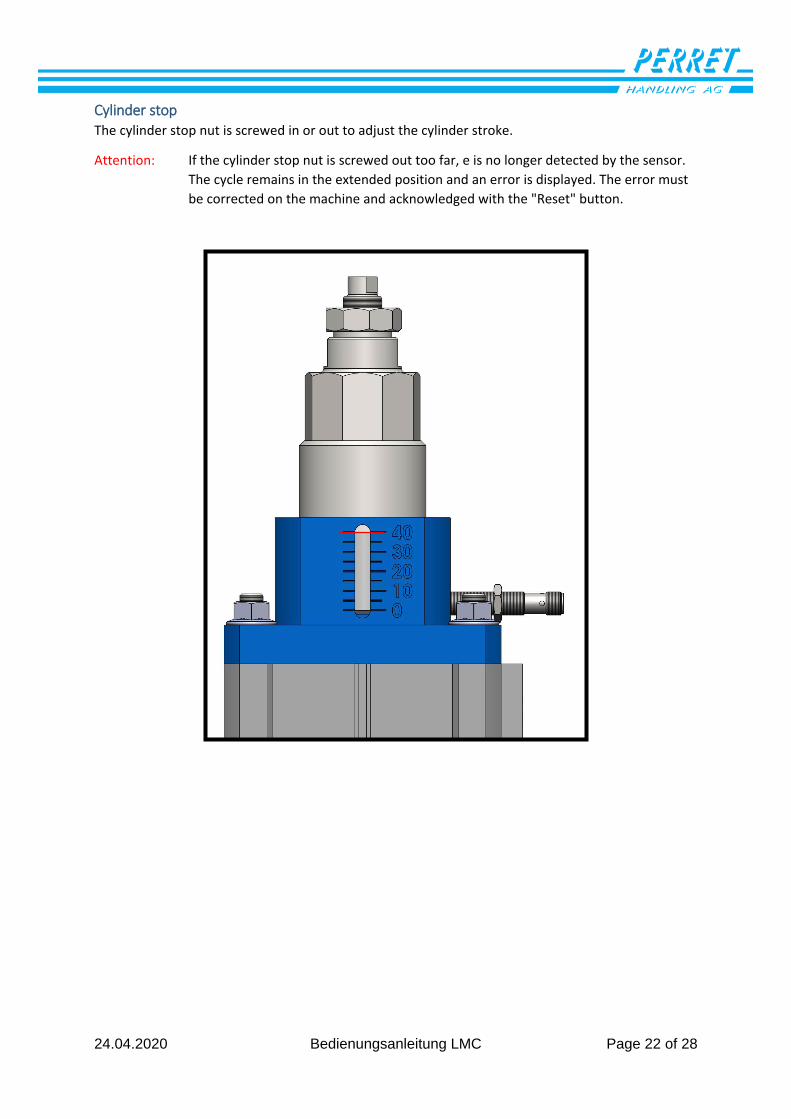
Cylinder stop The cylinder stop nut is screwed in or out to adjust the cylinder stroke.
Attention: If the cylinder stop nut is screwed out too far, e is no longer detected by the sensor.
The cycle remains in the extended position and an error is displayed. The error must
be corrected on the machine and acknowledged with the "Reset" button.
24.04.2020 Bedienungsanleitung LMC Page 23 of 28
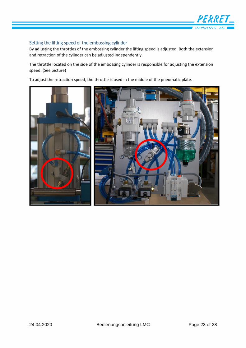
Setting the lifting speed of the embossing cylinder By adjusting the throttles of the embossing cylinder the lifting speed is adjusted. Both the extension
and retraction of the cylinder can be adjusted independently.
The throttle located on the side of the embossing cylinder is responsible for adjusting the extension
speed. (See picture)
To adjust the retraction speed, the throttle is used in the middle of the pneumatic plate.
24.04.2020 Bedienungsanleitung LMC Page 24 of 28
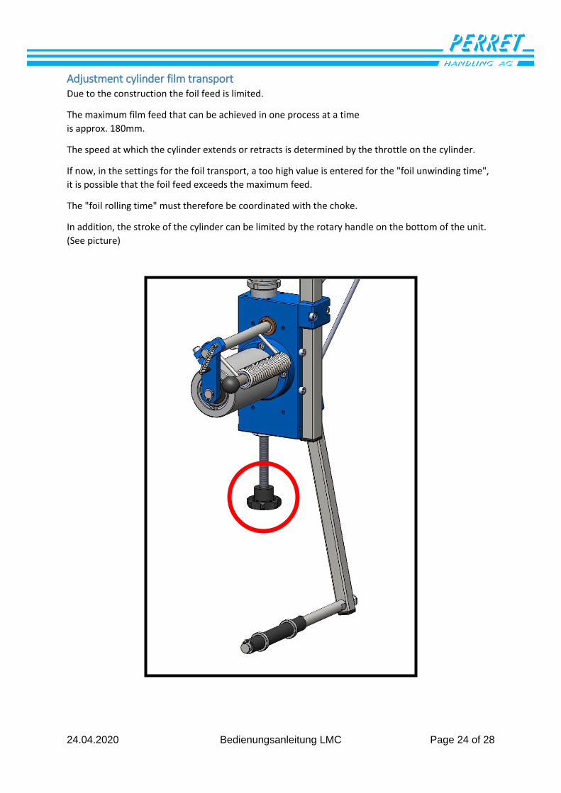
Adjustment cylinder film transport Due to the construction the foil feed is limited.
The maximum film feed that can be achieved in one process at a time
is approx. 180mm.
The speed at which the cylinder extends or retracts is determined by the throttle on the cylinder.
If now, in the settings for the foil transport, a too high value is entered for the "foil unwinding time",
it is possible that the foil feed exceeds the maximum feed.
The "foil rolling time" must therefore be coordinated with the choke.
In addition, the stroke of the cylinder can be limited by the rotary handle on the bottom of the unit.
(See picture)
24.04.2020 Bedienungsanleitung LMC Page 25 of 28
Coupling height adjustment Embossing head The electronic height adjustment of the embossing head is equipped with a safety clutch to prevent
the motor from overheating and the spindle from jamming.
When the embossing head is moved to the stop (up/down), the clutch engages and allows the motor
to rotate. When driving in the opposite direction, the clutch re-engages.
If the clutch does not re-engage directly, you can try to find the engaged position by briefly pressing
the "Start" button (in manual mode).
Attention: If you drive with a lot of momentum to the lower stop it can happen that the clutch
gets tightened by the high torque. If the clutch does not re-engage when driving up,
it must be released manually. (See instructions below).
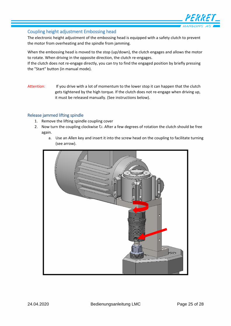
Release jammed lifting spindle 1. Remove the lifting spindle coupling cover
2. Now turn the coupling clockwise ↻. After a few degrees of rotation the clutch should be free
again.
a. Use an Allen key and insert it into the screw head on the coupling to facilitate turning
(see arrow).
24.04.2020 Bedienungsanleitung LMC Page 26 of 28
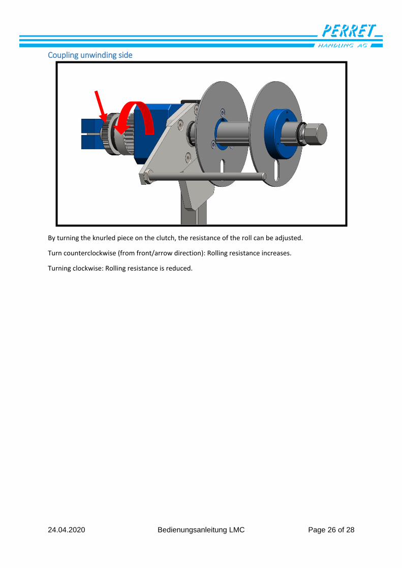
Coupling unwinding side
By turning the knurled piece on the clutch, the resistance of the roll can be adjusted.
Turn counterclockwise (from front/arrow direction): Rolling resistance increases.
Turning clockwise: Rolling resistance is reduced.
24.04.2020 Bedienungsanleitung LMC Seite 27 von 28
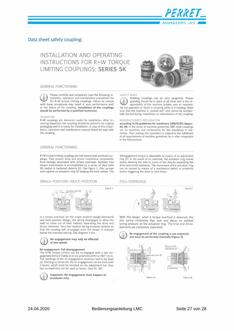
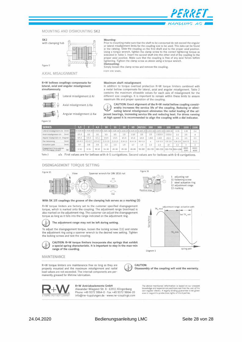
Data sheet safety coupling:
24.04.2020 Bedienungsanleitung LMC Seite 28 von 28
Recommended