NCC Medical Co., Ltd
Http://www.cnnation.com
Technical User’s Manual
Type C EEG System
Operation Manual
Nation7128W

Table of Contents Notice to Users ........................................................................................................................ 1
Rights and Responsibilities .............................................................................................. 5
Copyright Reservation ......................................................................................................... 5
Chapter 1 Hardware Configurations & Connections .......................................... 6
1.1 System Hardware Configuration .................................................................. 6
1.2 Hardware Operational Instructions ............................................................ 7
1.3 Hardware Technical Parameters ................................................................ 16
Chapter 2 Software Installation .................................................................................. 17
2.1 Software Installation Requirements ........................................................ 17
2.2 Software Installation Procedure ................................................................ 17
2.3 Serial No. Setup .................................................................................................... 19
2.4 EEG Montage & Leads Configuration ........................................................ 19
Chapter 3 Main Interface Operation ......................................................................... 22
3.1Toolbar ........................................................................................................................ 22
3.2 Data Directory Selection.................................................................................. 23
3.3 Case Library Drop-List ...................................................................................... 24
3.4 Case Library and Case Information Display......................................... 24
3.5 Management of Case Library ........................................................................ 25
3.6 User Information ................................................................................................. 26
3.7 Function Keys ......................................................................................................... 26
Chapter 4 Data Acquisition ............................................................................................. 31
4.1 Main Control Bar ................................................................................................... 31
4.2 Functional Menu Bar .......................................................................................... 32
Chapter 5 Playback and Analysis ................................................................................ 37
5.1 Playback .................................................................................................................... 37
5.2 Brain Electrical Activity Mapping Analysis ............................................ 43
5.3 Analysis ..................................................................................................................... 46
Chapter 6 Important Safety Information .............................................................. 49
6.1 Classification .......................................................................................................... 49
6.2 Device symbols ..................................................................................................... 49
Chapter 7 Maintenance & Servicing .......................................................................... 50
7.1 Cleaning and Disinfection ............................................................................... 50
7.2 Appearance Inspections .................................................................................. 51
7.3 Troubleshooting ................................................................................................... 52
7.4 Transportation and Storage Conditions ................................................. 53
Appendix A: Manufacturer Information .................................................................. 54
Appendix B: Power Supply & Battery Operation ............................................... 54
Appendix C: Electromagnetic Compatibility ......................................................... 54

1
Notice to Users Users are advised to read this manual carefully before using this
equipment. The Users should follow the operation steps that is
consisted in this manual, otherwise it would lead to abnormal
operation results and cause damage to the equipment or even cause
injuries and physical dangers to the user. The company does not hold
any responsibility for any property damages, injuries or physical
dangers caused by the misuse of this equipment.
Precautions on using this device:
Equipment installation environment and location requirements:
Ensure the power switch is off when installing the device. The device should
only be switched on during examinations;
The location should have good ventilation to remove gases in the air which
will either affect the readings or cause danger to the users and patients;
There are temperature and humidity control device to ensure that the
appropriate test subjects skin temperature, the room temperature
maintained at 20°C ~ 24°C, humidity 20% to 80% is appropriate;
The location should have controlled lighting, preferably incandescent;
There should be a shading device in the location to help achieving better
results for flash-induced EEG examinations and sleep analysis;
The location should be soundproof to prevent external noise interference
during AEP examinations;
The device should be placed away from electrical instruments,
high-frequency radiant point, etc. to avoid interference during examination;
The location should have a special hand-washing station installed for the
convenience of use. After all, all operating personnel and the patient should
wash their hands first to release static electricity before the examination;
The device should be kept away from moisture or water, extreme air
pressure, excessive humidity and temperature, poor ventilation and acid
gas or alkaline dust during the examination;
Use of this device is not advisable in the presence of any flammable
anesthetics to prevent voltaic arc which may cause explosion;
This device is not suitable for use in places with chemical storage or gas
chambers such as a medical hyperbaric oxygen chamber, as it may
triggeran explosion or fire.
Type C EEG Operation Manual
2
Ground wire connection requirements of equipment:
This equipment complies with Class I in GB9706.1;
The ground wire must be used with the supplied 3-pin power plug.
Otherwise, it may cause electric shock to the patient and the operator;
An effective connection with the potential equalization terminal should be
secured for safe grounding;
When several medical devices are used together, all devices should be
grounded at the same place to prevent any potential differences between
the devices, which may cause electric shock to the patient and operating
personnel.
Precautionary Steps
1. Before Operation:
Check to ensure that the equipment is cleaned and are in good operating
conditions;
Place the equipment in appropriate position;
Make sure all the wire connections and lead connections are correct;
When the device is used with other instruments, extra measures should be
taken to avoid diagnostic errors or other problems, such as making sure
they share the same grounding;
Examinees should be notified that:
Taking food before the EEG examination may affect the result of the
examination;
They should wash their head and hair the night before the examination
They should stop taking medicine that may influence the central
nervous system 3 days before the examination;
They should remain calm, as the examination is painless and has no
side effects;
Children who refuse to cooperate in the examination may need to be
sedated with chloral hydrate or its equivalent.
2. During Operation:
Both the patient and the instruments should be given sustained, careful
attention;
To ensure patient‟s safety, switch off the power before removing the
electrodes and/or sensors, even just to switch the electrode positions;
Patient should avoid touching the devices directly for safety reasons.
Type C EEG Operation Manual
3
3. After Operation:
Return all the devices back to initial position before switching them off;
Gently remove the electrode line;
Clean the equipment and accessories for future use.
Other Notes:
Do not use this device for other uses than medical examinations;
If the device is connected with multiple instruments on the same patient
simultaneously, superimposed leakage current of each instrument will
cause security risk. Any such combination should be checked by relevant
security personnel before it is being put into use;
Removable multi-jack provided with the EEG system package is strictly for
use with instruments within the original system only;
When the system power is powered by the removable multi-jack socket with
isolation transformer, user should not connect non-medical electrical
equipment to the wall outlet directly;
The equipment parts that are in physical contact with human body after
equipment should be confirmed to be working in stable condition;
This amplifier of this instrument is powered by rechargeable battery, which
should be charged before operation;
The Acoustic & Visual stimulation for the stimulator is designed specifically
to meet the general safety requirements;
For instrument power supply, voltage and frequency of power supply used
for this instrument must correspond to the specifications in the manual;
The EEG amplifier, receiver, electrodes and stimulator are medical electrical
devices designed for use in a clinical environment;
Maximum allowable load for removable multi-jack socket is 2500VA;
Do not connect device electrodes to other conductive parts of the device or
to the ground;
The equipment and its attachments should be examined regularly;
This device does not have anti-defibrillation function, so it cannot be used
together with the defibrillator or any high-frequency surgical equipment;
When the device is used together with other equipment (such as a
pacemaker or electrical stimulation), safety of the combination should be
confirmed by clinical engineers, so it will not affect the equipment's
diagnostic results or cause harm to the patient.
Warning: Removable multi-jack socket should not be placed on the ground.
Type C EEG Operation Manual
4
Requirements for Accessories:
All accessories used together with the device should be approved by the
Company. Unapproved device and accessories will affect the effectiveness of the
instrument and safety to the users and patient.
Staff Requirements:
Operator must be trained, have some skills before they can operate the
equipment;
Operators must be familiar with electrical safety knowledge.
Warning: Computer, monitor and printer used with this equipment should meet
national safety standards, and the power supply to the medical equipment
should be insulated using an isolation transformer unit.
Clinical usage:
This device is designed for Electroencephalogram (EEG) monitoring and brain
evoked potential examination.
Indications of Use:
Diagnosis, sorting, prognosis & directions in drug use on epilepsy patients;
Diagnosis of cephalitis;
Diagnosis of Creutzfeldt-Jakob disease (CJD);
Diagnosis of subacute sclerosing panencephalitis (SSPE), also known as
Dawson disease or Dawson encephalitis;
Diagnosis to determine brain death status;
Distinguishing between coma and pseudo-coma;
Evaluation of sleep-disorder;
Monitoring of brain functionality during & after surgery;
Brain function evaluation to identify other diseases that affect the central
nervous system.
Contraindications:
Those with the following medical conditions should be advised against
undergoing the optional stimulation test module:
Patients with cardiac pacemakers or cardiac catheterization;
Patients with skin diseases;
Patients with bleeding tendencies;
Type C EEG Operation Manual
5
Patients who are susceptible to recurrent and/or systemic infections.
Applicability statement:
This manual is only applicable for Type-C EEG Systems stated below:
Nation 7128W
20/40 channels Digital EEG
Nation 7128WH
20/40 channels Ambulatory EEG
Rights and Responsibilities Information in text is subject to change, and the details of the changes will be
embodied in the updated version. NCC Medical does not assume responsibility
for any use or reliability for the software and device which is not provided by
NCC Medical or NCC's distributor.
Copyright Reservation NCC Medical Co., Ltd. reserves all rights to the copyright of this publication. This
manual is only for personal use of buyers, and any part of this manual cannot be
reproduced or transmitted, including photocopying and recording in any form or
by any means (electronic or mechanical) without the written permission of NCC
Medical Co., Ltd.
Type C EEG Operation Manual
6
Chapter 1 Hardware Configurations & Connections
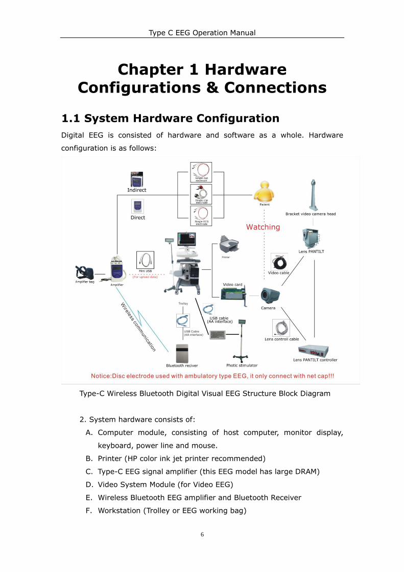
1.1 System Hardware Configuration
Digital EEG is consisted of hardware and software as a whole. Hardware
configuration is as follows:
Type-C Wireless Bluetooth Digital Visual EEG Structure Block Diagram
2. System hardware consists of:
A. Computer module, consisting of host computer, monitor display,
keyboard, power line and mouse.
B. Printer (HP color ink jet printer recommended)
C. Type-C EEG signal amplifier (this EEG model has large DRAM)
D. Video System Module (for Video EEG)
E. Wireless Bluetooth EEG amplifier and Bluetooth Receiver
F. Workstation (Trolley or EEG working bag)
Type C EEG Operation Manual
7
G. Mini USB data cable (for dynamic data uploading)
H. Electrodes (Routine EEG checking equips regular electrodes,
long-time brain electricity monitor, dynamic EEG checking equips
brain electricity monitoring electrodes, epilepsy surgery special
equipment equips surgery use electrodes).
1.2 Hardware Operational Instructions
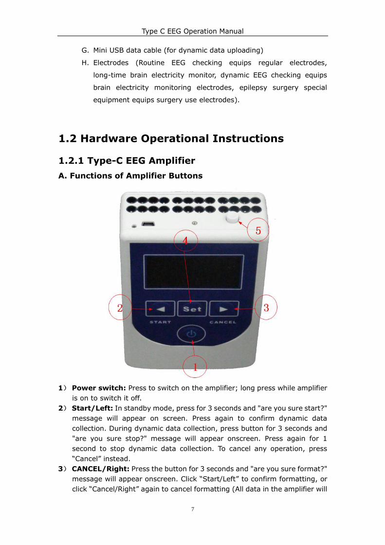
1.2.1 Type-C EEG Amplifier
A. Functions of Amplifier Buttons
1) Power switch: Press to switch on the amplifier; long press while amplifier
is on to switch it off.
2) Start/Left: In standby mode, press for 3 seconds and "are you sure start?"
message will appear on screen. Press again to confirm dynamic data
collection. During dynamic data collection, press button for 3 seconds and
"are you sure stop?" message will appear onscreen. Press again for 1
second to stop dynamic data collection. To cancel any operation, press
“Cancel” instead.
3) CANCEL/Right: Press the button for 3 seconds and "are you sure format?"
message will appear onscreen. Click “Start/Left” to confirm formatting, or
click “Cancel/Right” again to cancel formatting (All data in the amplifier will
Type C EEG Operation Manual
8
be deleted by formatting).
4) Set: Press for 5 seconds to change settings of dynamic EEG data collection,
including EEG channel numbers. When the channel number flashes, press
“Start/Left” key to switch channel numbers.
5) Event button: In dynamic recording mode, press this key will record the
time when you press the button in the DRAM; after dynamic recording mode
is ended, upload the data to the computer, the user may see the event
marked time within the uploaded data (E.g. Patient presses the key during
an epilepsy attack. After uploading the data, the staff can determine the
time of epilepsy attack on patient based on the event marked.).
6) Combination:
i. Power and Cancel/Right: Pressing “Power” and “Cancel/Right”
buttons together will lock the amplifier buttons. The buttons will not
work unless the two buttons are pressed again to unlock it.
ii. Start/Left and Cancel/Right: Pressing “Start/Left” and
“Cancel/Right” together to switch to waveform display mode. Press
“Start/Left” to switch the channel of the waveform displayed. Press
“Start/Left” and “Cancel/Right” together again to restore the main
interface.
iii. Cancel/Right and Setting: Press “Cancel/Right” and “Setting”
together to switch on or off the wireless Bluetooth connection. If the
Bluetooth has been connected, the connection will be disconnected; if
the Bluetooth has not been connected, the amplifier will search and set
up connection with the nearest Bluetooth receiver.
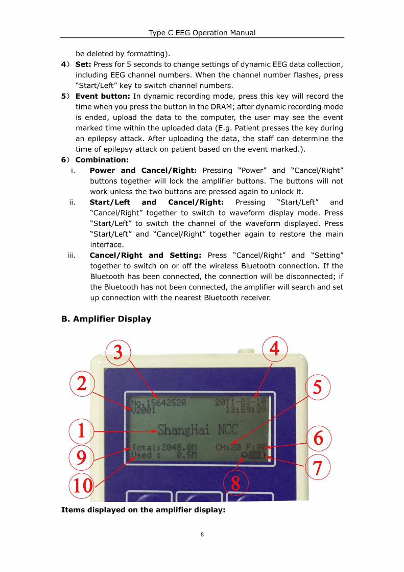
B. Amplifier Display
Items displayed on the amplifier display:
Type C EEG Operation Manual
9
1. Company name display, occasionally displays messages like “Are you sure
format?” etc.;
2. Product hardware revision number;
3. Product serial number display;
4. Date and time display. This can be synchronized with the date and time
displayed in the PC;
5. Hardware channel number display: After starting up, it will display the
current hardware channel numbers. In dynamic data collecting mode, user
may set up the number of data collecting channels;
6. Sampling rate display: Shows the current sampling rate: 00 = 128Hz, 01 =
256Hz, 02 = 512Hz;
7. Battery status display;
8. Bluetooth Connection Status: shows the current status of Bluetooth
connectivity, such as the ones shown below:
Connected via
USB Cable
Searching for
Bluetooth
No Bluetooth
Connection
Connected via
Bluetooth
Acquisition of
Status
9. Flash memory status: displays the total memory capacity of the DRAM;
10. Used flash memory: displays the quantity of dynamic data recorded;
11. During dynamic recording mode, the system time and recording time will be
displayed at the centre of the screen.
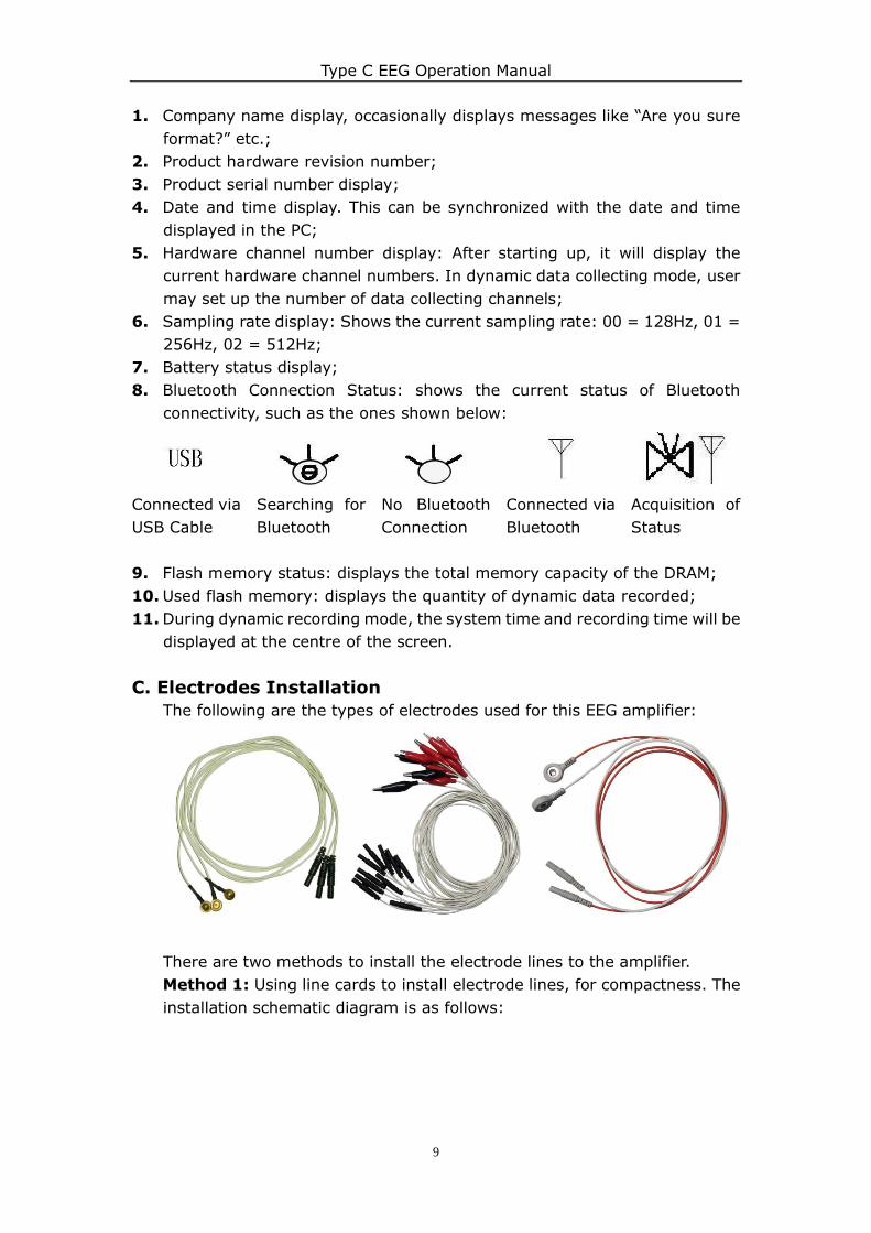
C. Electrodes Installation
The following are the types of electrodes used for this EEG amplifier:
There are two methods to install the electrode lines to the amplifier.
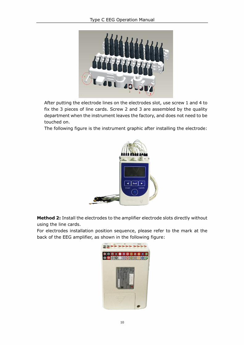
Method 1: Using line cards to install electrode lines, for compactness. The
installation schematic diagram is as follows:
Type C EEG Operation Manual
10
After putting the electrode lines on the electrodes slot, use screw 1 and 4 to
fix the 3 pieces of line cards. Screw 2 and 3 are assembled by the quality
department when the instrument leaves the factory, and does not need to be
touched on.
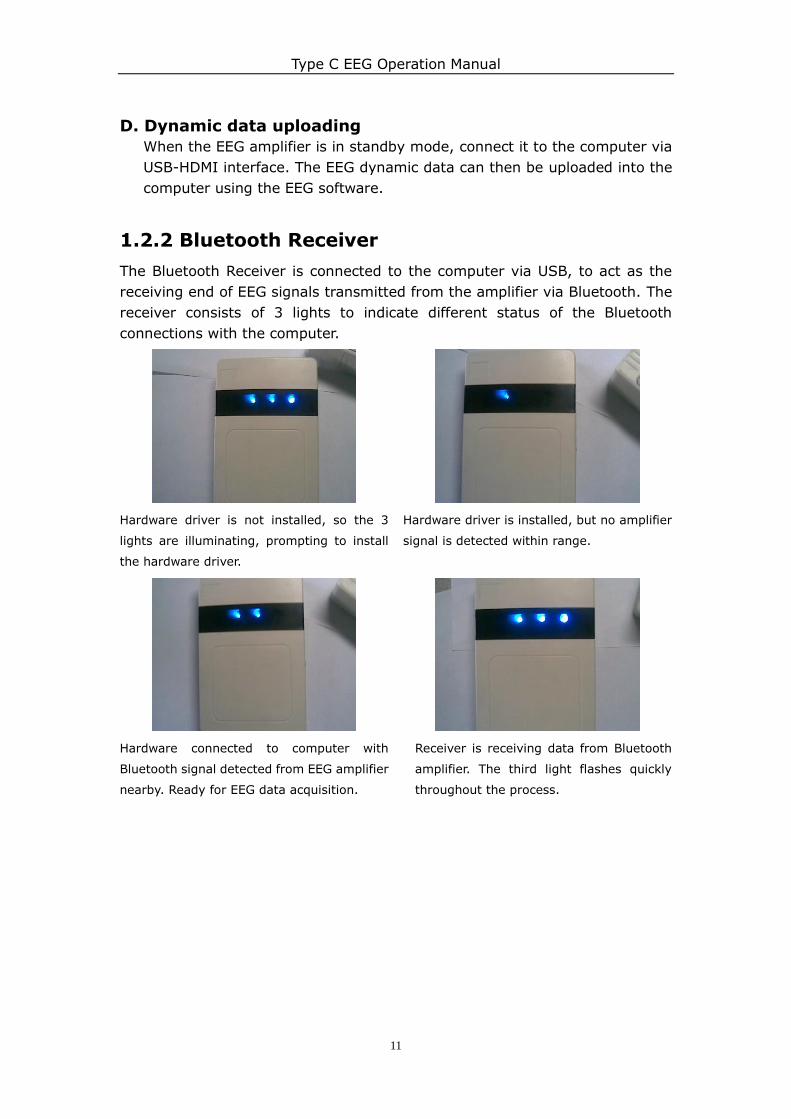
The following figure is the instrument graphic after installing the electrode:
Method 2: Install the electrodes to the amplifier electrode slots directly without
using the line cards.
For electrodes installation position sequence, please refer to the mark at the
back of the EEG amplifier, as shown in the following figure:
Type C EEG Operation Manual
11
D. Dynamic data uploading
When the EEG amplifier is in standby mode, connect it to the computer via
USB-HDMI interface. The EEG dynamic data can then be uploaded into the
computer using the EEG software.
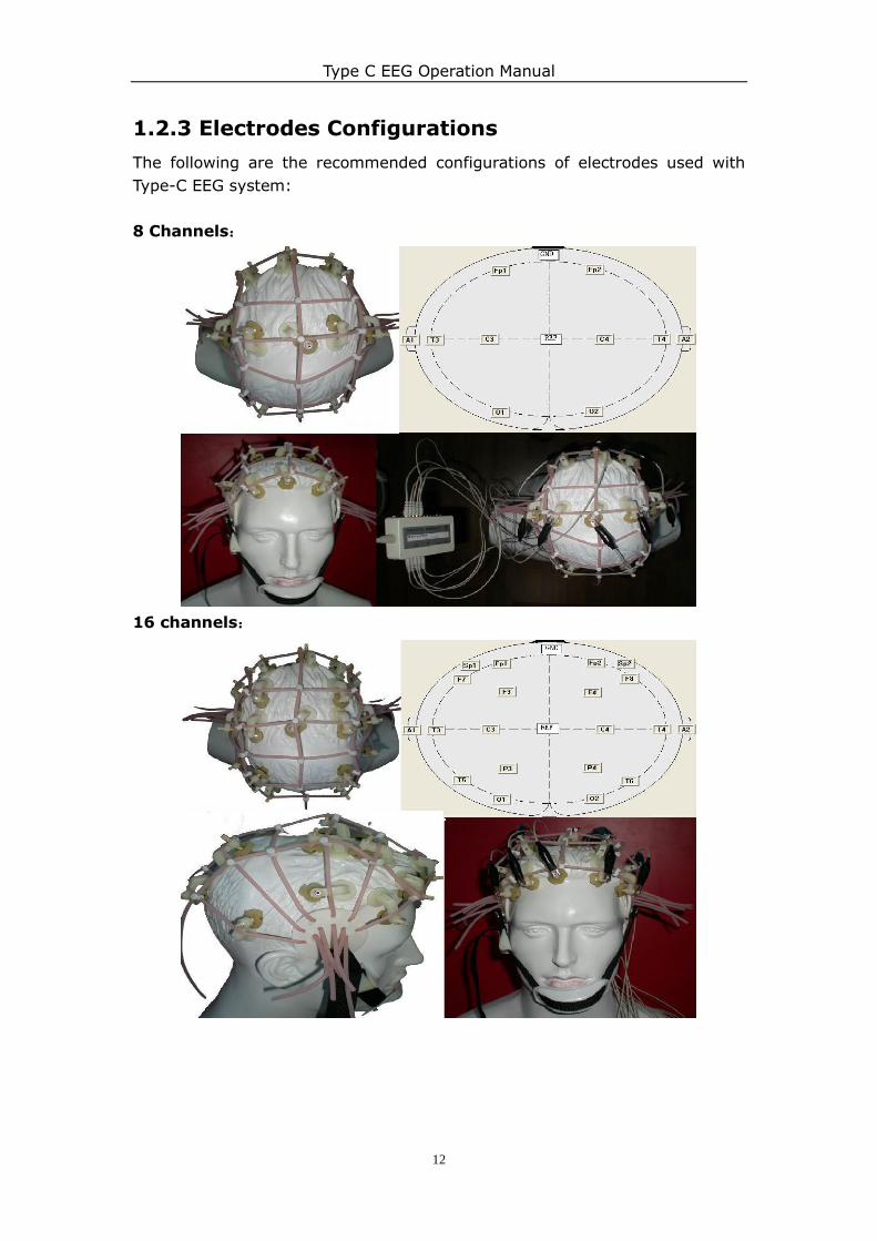
1.2.2 Bluetooth Receiver
The Bluetooth Receiver is connected to the computer via USB, to act as the
receiving end of EEG signals transmitted from the amplifier via Bluetooth. The
receiver consists of 3 lights to indicate different status of the Bluetooth
connections with the computer.
Hardware driver is not installed, so the 3
lights are illuminating, prompting to install
the hardware driver.
Hardware driver is installed, but no amplifier
signal is detected within range.
Hardware connected to computer with
Bluetooth signal detected from EEG amplifier
nearby. Ready for EEG data acquisition.
Receiver is receiving data from Bluetooth
amplifier. The third light flashes quickly
throughout the process.
Type C EEG Operation Manual
12
1.2.3 Electrodes Configurations
The following are the recommended configurations of electrodes used with
Type-C EEG system:
8 Channels:
16 channels:
Type C EEG Operation Manual
13
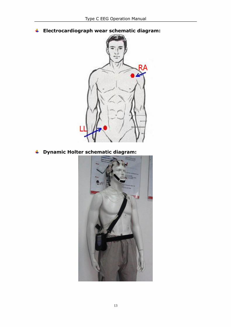
Electrocardiograph wear schematic diagram:
Dynamic Holter schematic diagram:
Type C EEG Operation Manual
14
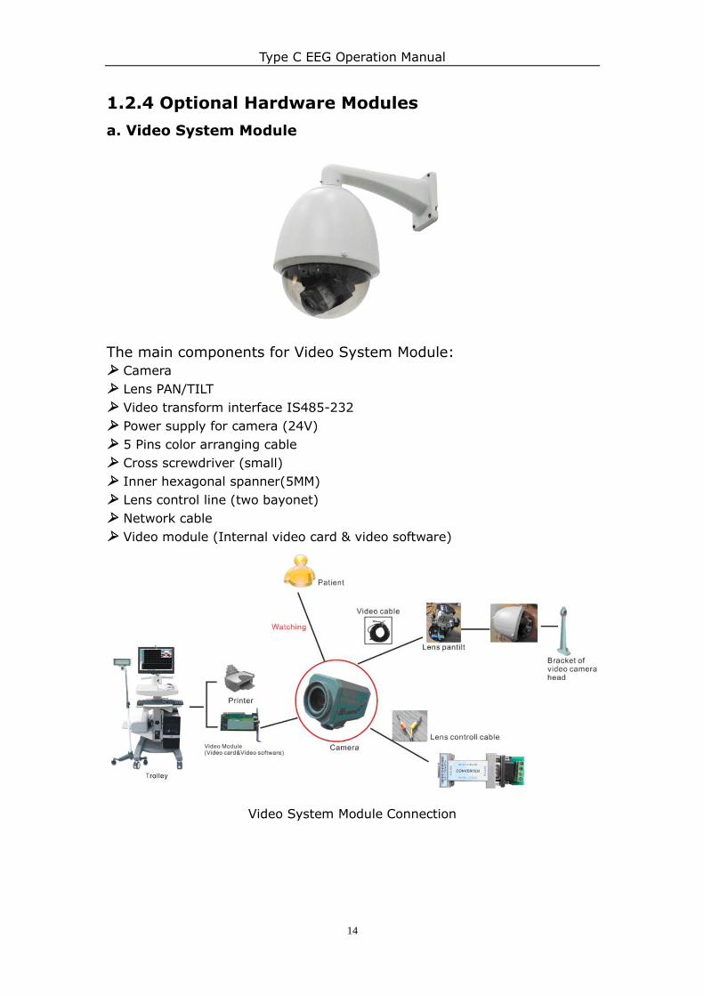
1.2.4 Optional Hardware Modules
a. Video System Module
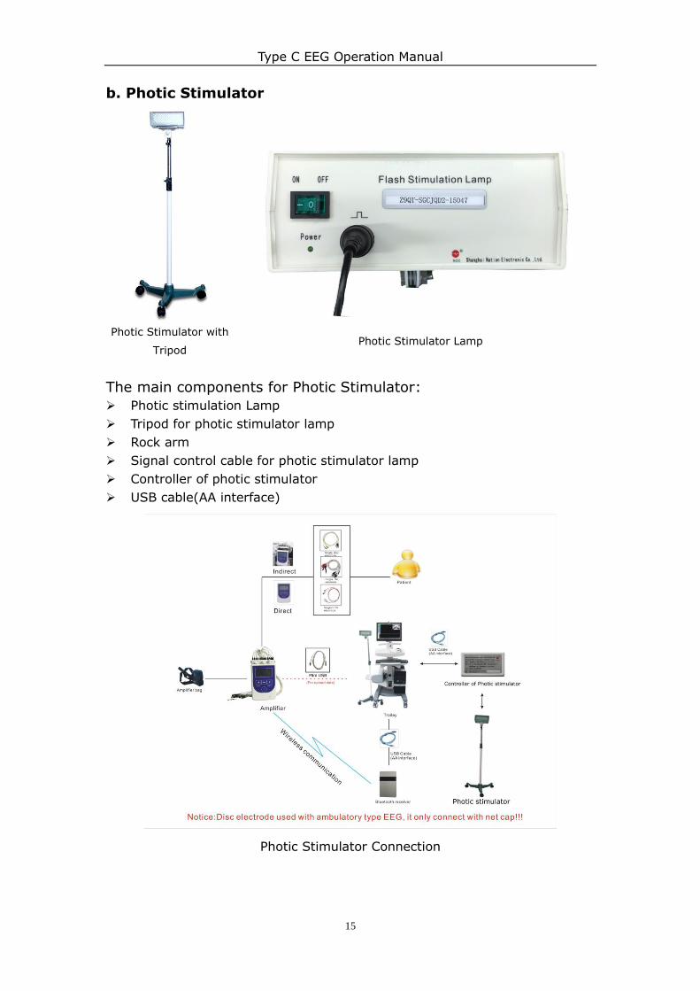
The main components for Video System Module:
Camera
Lens PAN/TILT
Video transform interface IS485-232
Power supply for camera (24V)
5 Pins color arranging cable
Cross screwdriver (small)
Inner hexagonal spanner(5MM)
Lens control line (two bayonet)
Network cable
Video module (Internal video card & video software)
Video System Module Connection
Type C EEG Operation Manual
15
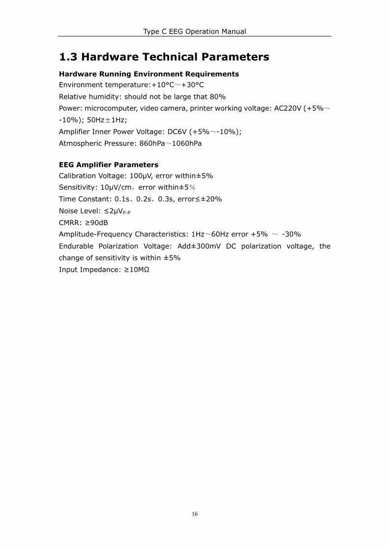
b. Photic Stimulator
Photic Stimulator with
Tripod Photic Stimulator Lamp
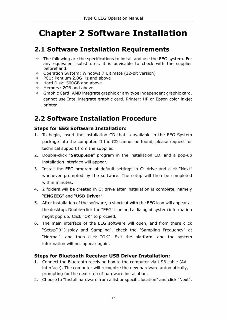
The main components for Photic Stimulator:
Photic stimulation Lamp
Tripod for photic stimulator lamp
Rock arm
Signal control cable for photic stimulator lamp
Controller of photic stimulator
USB cable(AA interface)
Photic Stimulator Connection
Type C EEG Operation Manual
16
1.3 Hardware Technical Parameters
Hardware Running Environment Requirements
Environment temperature:+10°C~+30°C
Relative humidity: should not be large that 80%
Power: microcomputer, video camera, printer working voltage: AC220V (+5%~
-10%); 50Hz±1Hz;
Amplifier Inner Power Voltage: DC6V (+5%~-10%);
Atmospheric Pressure: 860hPa~1060hPa
EEG Amplifier Parameters
Calibration Voltage: 100μV, error within±5%
Sensitivity: 10μV/cm,error within±5%
Time Constant: 0.1s、0.2s、0.3s, error≤±20%
Noise Level: ≤2μVP-P
CMRR: ≥90dB
Amplitude-Frequency Characteristics: 1Hz~60Hz error +5% ~ -30%
Endurable Polarization Voltage: Add±300mV DC polarization voltage, the
change of sensitivity is within ±5%
Input Impedance: ≥10MΩ
Type C EEG Operation Manual
17
Chapter 2 Software Installation
2.1 Software Installation Requirements
The following are the specifications to install and use the EEG system. For any equivalent substitutes, it is advisable to check with the supplier
beforehand. Operation System: Windows 7 Ultimate (32-bit version) PCU: Pentium 2.0G Hz and above
Hard Disk: 500GB and above Memory: 2GB and above
Graphic Card: AMD integrate graphic or any type independent graphic card,
cannot use Intel integrate graphic card. Printer: HP or Epson color inkjet
printer
2.2 Software Installation Procedure
Steps for EEG Software Installation:
1. To begin, insert the installation CD that is available in the EEG System
package into the computer. If the CD cannot be found, please request for
technical support from the supplier.
2. Double-click “Setup.exe” program in the installation CD, and a pop-up
installation interface will appear.
3. Install the EEG program at default settings in C: drive and click “Next”
whenever prompted by the software. The setup will then be completed
within minutes.
4. 2 folders will be created in C: drive after installation is complete, namely
“ENGEEG” and “USB Driver”.
5. After installation of the software, a shortcut with the EEG icon will appear at
the desktop. Double-click the “EEG” icon and a dialog of system information
might pop up. Click “OK” to proceed.
6. The main interface of the EEG software will open, and from there click
“Setup”"Display and Sampling", check the "Sampling Frequency" at
“Normal”, and then click “OK”. Exit the platform, and the system
information will not appear again.
Steps for Bluetooth Receiver USB Driver Installation:
1. Connect the Bluetooth receiving box to the computer via USB cable (AA
interface). The computer will recognize the new hardware automatically,
prompting for the next step of hardware installation.
2. Choose to "Install hardware from a list or specific location" and click "Next".
Type C EEG Operation Manual
18
3. Choose the option "Include this location in the search", then set the target
directory as "C:\USB drive\ eegdy", or look for the driver file “eegpt.sys”.
Click "Yes" and then click "Next".
4. The system would install the driver program automatically. If any dialog
regarding "Hardware setup" pops up again, click "Continue anyway".
5. Once installation is completed, click “OK” to finish driver installation of
Bluetooth Receiver.
Steps for EEG Amplifier USB Driver Installation:
1. Sometimes the user needs to transfer EEG data stored within the amplifier
into the computer, which cannot be done via Bluetooth. This is the purpose
of installing the USB interface for EEG amplifier, so that these data can be
uploaded into the computer via Mini USB.
2. The installation steps for EEG amplifier is mostly the same as the installation
steps of the Bluetooth receiver, except the connection of EEG amplifier to
the computer is by Mini USB, and the driver directory is "C:\USBdrive\eegc".
The rest of the procedure is the same.
Steps for Photic Stimulator Installation (Optional):
4.1. Connect the photic stimulator to the computer by connecting a USB cable
(AA interface) with its controller. The computer will recognize the new hardware
automatically. A dialog frame "Find new hardware wizard" will pop up and
select "Yes, this time only", and then click "Next".
4.2. Select "Install from a list or specific location" and click "Next".
4.3. Select "Include this location in the search" and click "Next". Browse
pull-down menu and set the path as "target path: C\USB drive\ bluth". Then
click "Next".
4.4. The system will start to install driver automatically. The dialog frame of
"Hardware installation" would pop up, and click "Continue anyway".
4.5. click “ok “to finish installation.
Type C EEG Operation Manual
19
2.3 Serial No. Setup
1. Registering the EEG amplifier serial number into the software is important to
make sure that EEG amplifier is the only one recognized by the software, so
the software will not confuse its input with other EEG amplifiers or machines
in the vicinity.
2. Usually the serial number will be installed automatically after installing the
software. If not, please put the CD software into the computer, then copy the
file “stdgain.cfg” to “C:\ENGEEG\CFG” and replace the old one, the serial
number will be shown automatically.
2.4 EEG Montage & Leads Configuration
1. EEG leads can be configured from the Leads Edit/Montage Interface (See
Fig. 2-3) accessible from the system setup. The configurations may differ
slightly based on the EEG type selected and the inclusion of
multi-parameters.
2. At the Leads Edit/Montage Interface, click on the drop-down list box of
“Hardware Configuration” on the top left to select the EEG configuration
to be used. The columns below will display the existing EEG channel
configurations.
3. To create a new set of configuration, click “Add” on the top right list; to work
on a previously set channel configuration, click on “Edit” instead.
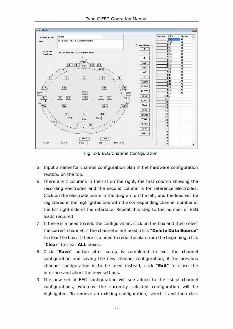
4. The EEG channel configuration is shown in Fig. 2-6, displaying a diagram
with selectable EEG channels on the left and the current EEG channel
configuration on the right. If the EEG type selected includes
“multi-parameter”, an expanded data list will be shown in the middle.
Type C EEG Operation Manual
20
Fig. 2-6 EEG Channel Configuration
5. Input a name for channel configuration plan in the hardware configuration
textbox on the top.
6. There are 2 columns in the list on the right, the first column showing the
recording electrodes and the second column is for reference electrodes.
Click on the electrode name in the diagram on the left, and the lead will be
registered in the highlighted box with the corresponding channel number at
the list right side of the interface. Repeat this step to the number of EEG
leads required.
7. If there is a need to redo the configuration, click on the box and then select
the correct channel; if the channel is not used, click “Delete Data Source”
to clear the box; if there is a need to redo the plan from the beginning, click
“Clear” to clear ALL boxes.
8. Click "Save" button after setup is completed to exit the channel
configuration and saving the new channel configuration; if the previous
channel configuration is to be used instead, click “Exit” to close the
interface and abort the new settings.
9. The new set of EEG configuration will see added to the list of channel
configurations, whereby the currently selected configuration will be
highlighted. To remove an existing configuration, select it and then click
Type C EEG Operation Manual
21
“Delete”.
10. When the EEG amplifier is registered into the software and the EEG channel
configuration is completed, click “Exit” to close the Leads Edit/Montage
Interface.
WARNING: Do not change the data source without guidance, or the
software may not work properly.
Type C EEG Operation Manual
22
Chapter 3 Main Interface
Operation
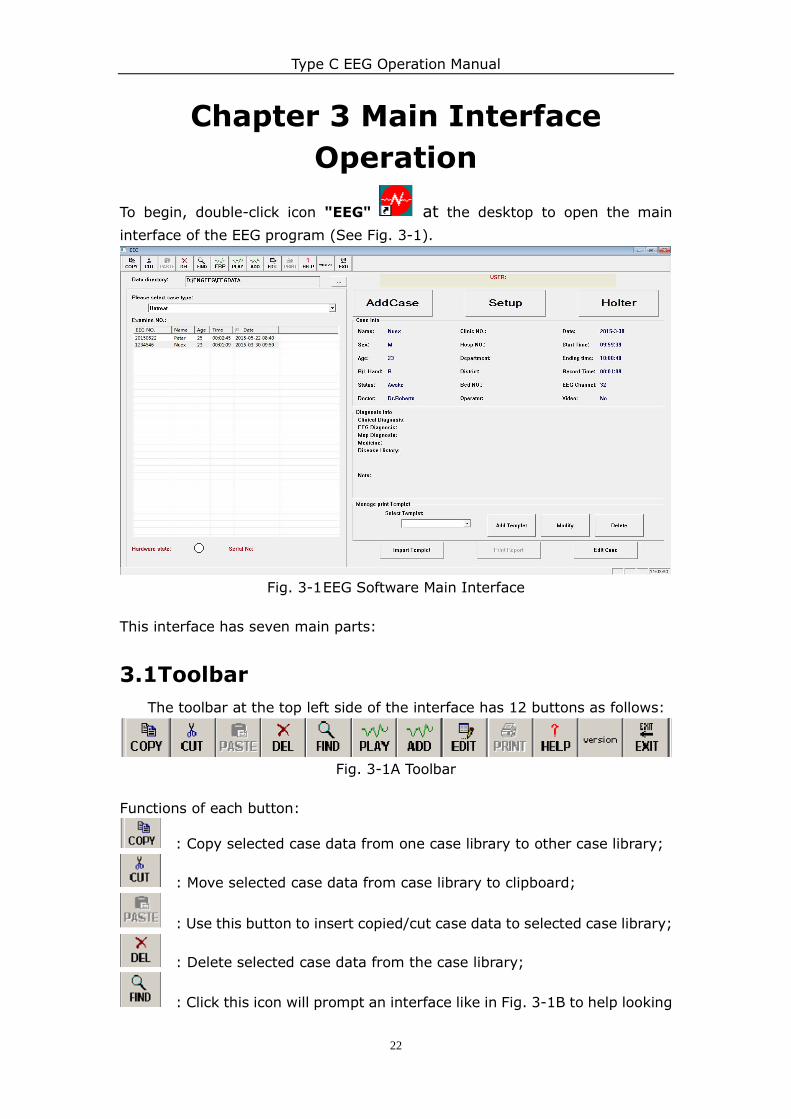
To begin, double-click icon "EEG" at the desktop to open the main
interface of the EEG program (See Fig. 3-1).
Fig. 3-1 EEG Software Main Interface
This interface has seven main parts:
3.1Toolbar
The toolbar at the top left side of the interface has 12 buttons as follows:
Fig. 3-1A Toolbar
Functions of each button:
: Copy selected case data from one case library to other case library;
: Move selected case data from case library to clipboard;
: Use this button to insert copied/cut case data to selected case library;
: Delete selected case data from the case library;
: Click this icon will prompt an interface like in Fig. 3-1B to help looking
Type C EEG Operation Manual
23
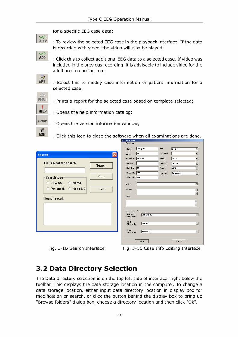
for a specific EEG case data;
: To review the selected EEG case in the playback interface. If the data
is recorded with video, the video will also be played;
: Click this to collect additional EEG data to a selected case. If video was
included in the previous recording, it is advisable to include video for the
additional recording too;
: Select this to modify case information or patient information for a
selected case;
: Prints a report for the selected case based on template selected;
: Opens the help information catalog;
: Opens the version information window;
: Click this icon to close the software when all examinations are done.
Fig. 3-1B Search Interface Fig. 3-1C Case Info Editing Interface
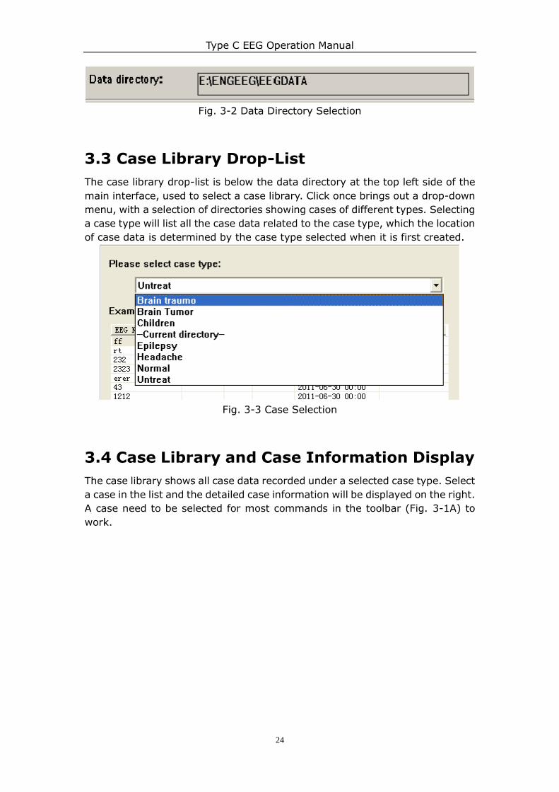
3.2 Data Directory Selection
The Data directory selection is on the top left side of interface, right below the
toolbar. This displays the data storage location in the computer. To change a
data storage location, either input data directory location in display box for
modification or search, or click the button behind the display box to bring up
"Browse folders" dialog box, choose a directory location and then click "Ok".
Type C EEG Operation Manual
24
Fig. 3-2 Data Directory Selection
3.3 Case Library Drop-List
The case library drop-list is below the data directory at the top left side of the
main interface, used to select a case library. Click once brings out a drop-down
menu, with a selection of directories showing cases of different types. Selecting
a case type will list all the case data related to the case type, which the location
of case data is determined by the case type selected when it is first created.
Fig. 3-3 Case Selection
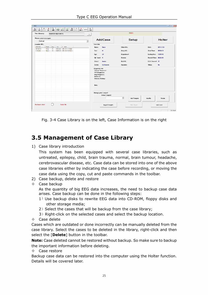
3.4 Case Library and Case Information Display
The case library shows all case data recorded under a selected case type. Select
a case in the list and the detailed case information will be displayed on the right.
A case need to be selected for most commands in the toolbar (Fig. 3-1A) to
work.
Type C EEG Operation Manual
25
Fig. 3-4 Case Library is on the left, Case Information is on the right
3.5 Management of Case Library
1) Case library introduction
This system has been equipped with several case libraries, such as
untreated, epilepsy, child, brain trauma, normal, brain tumour, headache,
cerebrovascular disease, etc. Case data can be stored into one of the above
case libraries either by indicating the case before recording, or moving the
case data using the copy, cut and paste commands in the toolbar.
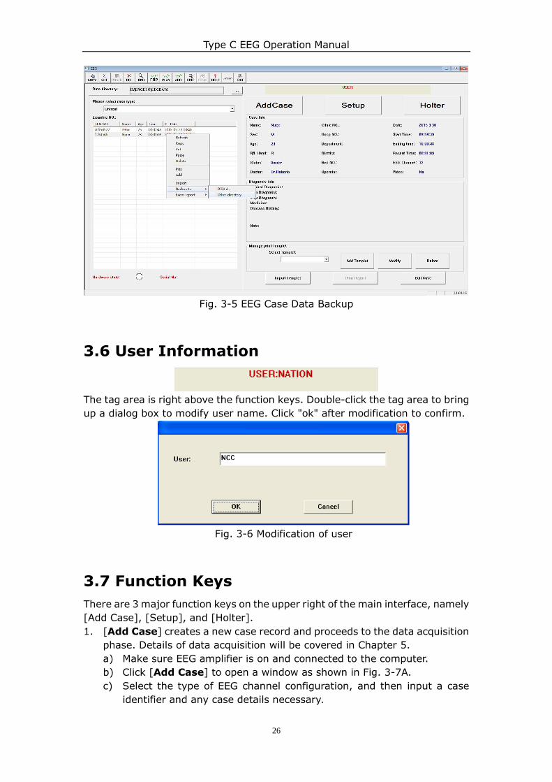
2) Case backup, delete and restore
Case backup
As the quantity of big EEG data increases, the need to backup case data arises. Case backup can be done in the following steps:
1)Use backup disks to rewrite EEG data into CD-ROM, floppy disks and
other storage media;
2)Select the cases that will be backup from the case library;
3)Right-click on the selected cases and select the backup location.
Case delete
Cases which are outdated or done incorrectly can be manually deleted from the
case library. Select the cases to be deleted in the library, right-click and then
select the [Delete] button in the toolbar.
Note: Case deleted cannot be restored without backup. So make sure to backup
the important information before deleting.
Case restore
Backup case data can be restored into the computer using the Holter function.
Details will be covered later.
Type C EEG Operation Manual
26
Fig. 3-5 EEG Case Data Backup
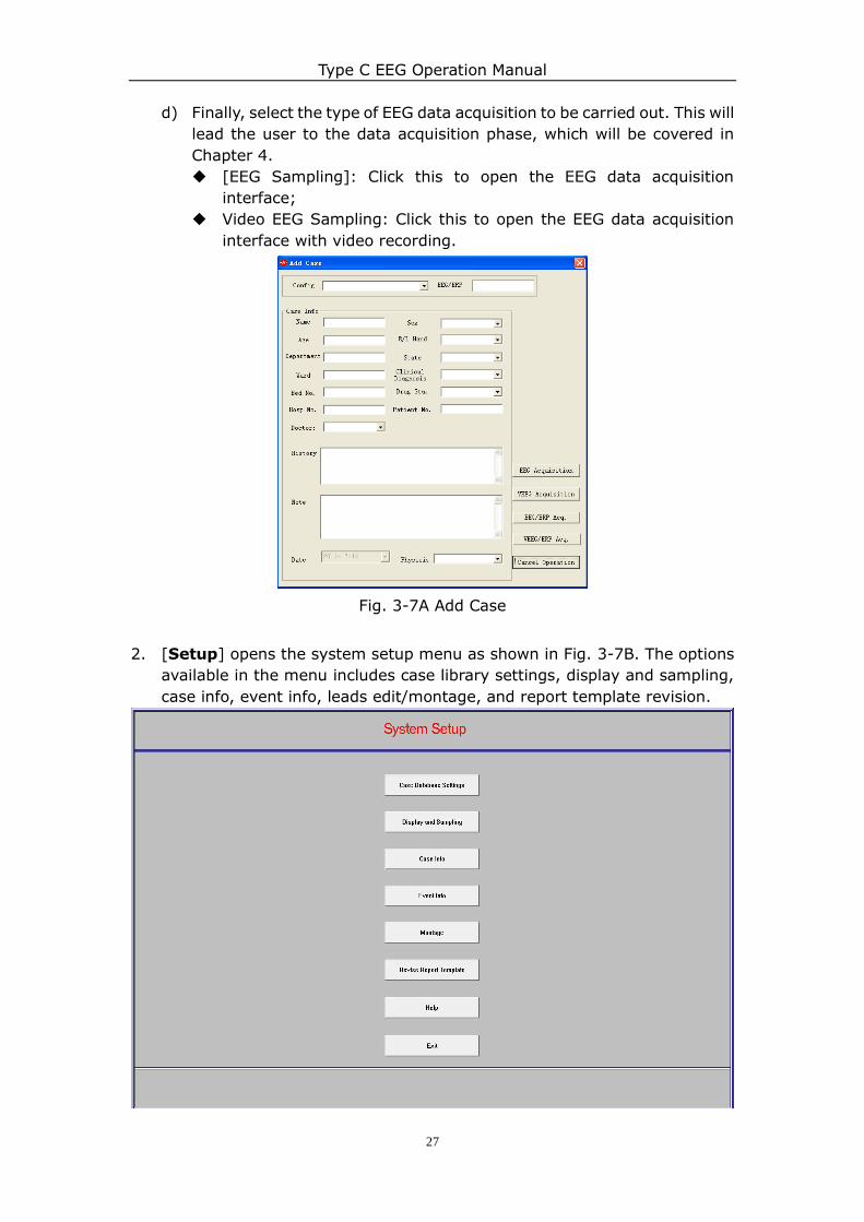
3.6 User Information
The tag area is right above the function keys. Double-click the tag area to bring
up a dialog box to modify user name. Click "ok" after modification to confirm.
Fig. 3-6 Modification of user
3.7 Function Keys
There are 3 major function keys on the upper right of the main interface, namely
[Add Case], [Setup], and [Holter].
1. [Add Case] creates a new case record and proceeds to the data acquisition
phase. Details of data acquisition will be covered in Chapter 5.
a) Make sure EEG amplifier is on and connected to the computer.
b) Click [Add Case] to open a window as shown in Fig. 3-7A.
c) Select the type of EEG channel configuration, and then input a case
identifier and any case details necessary.
Type C EEG Operation Manual
27
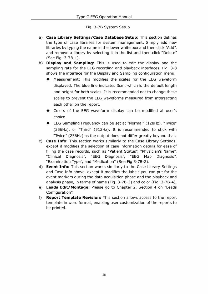
d) Finally, select the type of EEG data acquisition to be carried out. This will
lead the user to the data acquisition phase, which will be covered in
Chapter 4.
[EEG Sampling]: Click this to open the EEG data acquisition
interface;
Video EEG Sampling: Click this to open the EEG data acquisition
interface with video recording.
Fig. 3-7A Add Case
2. [Setup] opens the system setup menu as shown in Fig. 3-7B. The options
available in the menu includes case library settings, display and sampling,
case info, event info, leads edit/montage, and report template revision.
Type C EEG Operation Manual
28
Fig. 3-7B System Setup
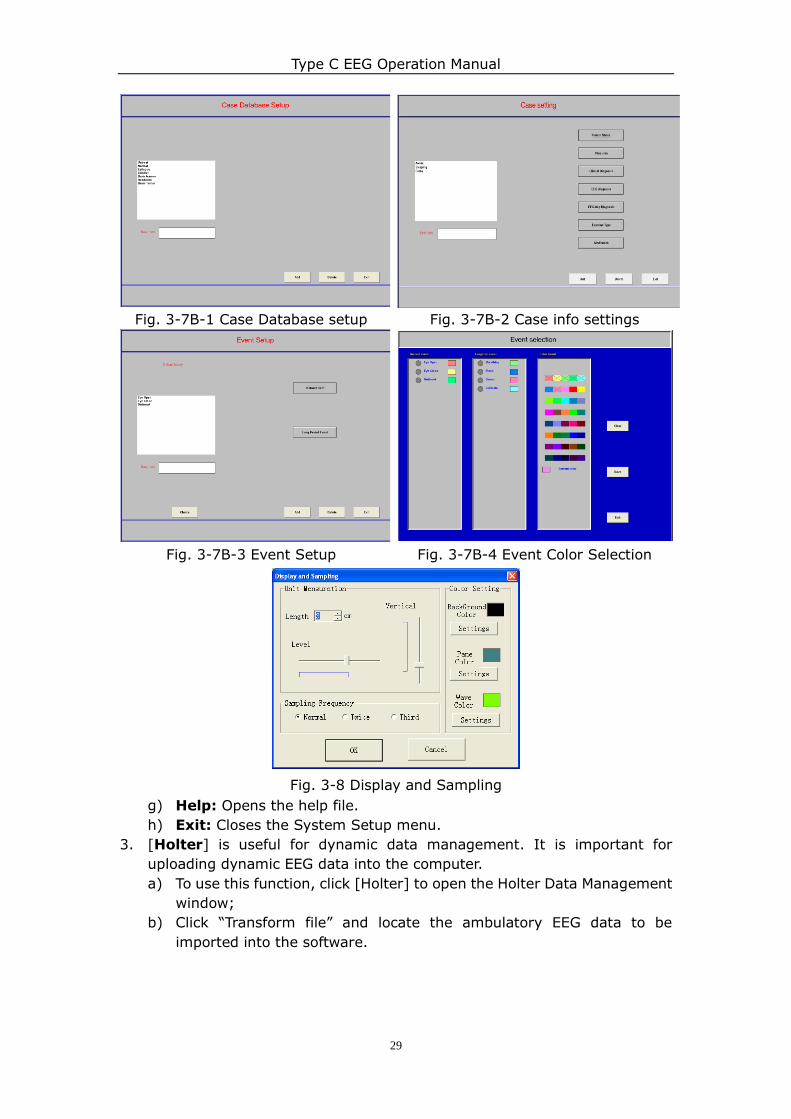
a) Case Library Settings/Case Database Setup: This section defines
the type of case libraries for system management. Simply add new
libraries by typing the name in the lower white box and then click “Add”,
and remove a library by selecting it in the list and then click “Delete”
(See Fig. 3-7B-1).
b) Display and Sampling: This is used to edit the display and the
sampling rate for the EEG recording and playback interfaces. Fig. 3-8
shows the interface for the Display and Sampling configuration menu.
Measurement: This modifies the scales for the EEG waveform
displayed. The blue line indicates 3cm, which is the default length
and height for both scales. It is recommended not to change these
scales to prevent the EEG waveforms measured from intersecting
each other on the report.
Colors of the EEG waveform display can be modified at user‟s
choice.
EEG Sampling Frequency can be set at “Normal” (128Hz), “Twice”
(256Hz), or “Third” (512Hz). It is recommended to stick with
“Twice” (256Hz) as the output does not differ greatly beyond that.
c) Case Info: This section works similarly to the Case Library Settings,
except it modifies the selection of case information details for ease of
filling the case records, such as “Patient Status”, “Physician‟s Name”,
“Clinical Diagnosis”, “EEG Diagnosis”, “EEG Map Diagnosis”,
“Examination Type”, and “Medication” (See Fig 3-7B-2).
d) Event Info: This section works similarly to the Case Library Settings
and Case Info above, except it modifies the labels you can put for the
event markers during the data acquisition phase and the playback and
analysis phase, in terms of name (Fig. 3-7B-3) and color (Fig. 3-7B-4).
e) Leads Edit/Montage: Please go to Chapter 2, Section 4 on “Leads
Configuration”.
f) Report Template Revision: This section allows access to the report
template in word format, enabling user customization of the reports to
be printed.
Type C EEG Operation Manual
29
Fig. 3-7B-1 Case Database setup Fig. 3-7B-2 Case info settings
Fig. 3-7B-3 Event Setup Fig. 3-7B-4 Event Color Selection
Fig. 3-8 Display and Sampling
g) Help: Opens the help file.
h) Exit: Closes the System Setup menu.
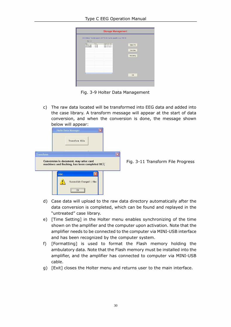
3. [Holter] is useful for dynamic data management. It is important for
uploading dynamic EEG data into the computer.
a) To use this function, click [Holter] to open the Holter Data Management
window;
b) Click “Transform file” and locate the ambulatory EEG data to be
imported into the software.
Type C EEG Operation Manual
30
Fig. 3-9 Holter Data Management
c) The raw data located will be transformed into EEG data and added into
the case library. A transform message will appear at the start of data
conversion, and when the conversion is done, the message shown
below will appear:
Fig. 3-11 Transform File Progress
d) Case data will upload to the raw data directory automatically after the
data conversion is completed, which can be found and replayed in the
“untreated” case library.
e) [Time Setting] in the Holter menu enables synchronizing of the time
shown on the amplifier and the computer upon activation. Note that the
amplifier needs to be connected to the computer via MINI-USB interface
and has been recognized by the computer system.
f) [Formatting] is used to format the Flash memory holding the
ambulatory data. Note that the Flash memory must be installed into the
amplifier, and the amplifier has connected to computer via MINI-USB
cable.
g) [Exit] closes the Holter menu and returns user to the main interface.
Type C EEG Operation Manual
31
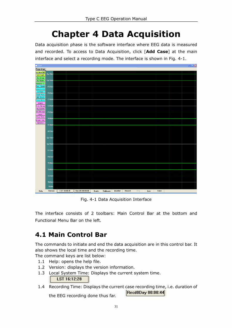
Chapter 4 Data Acquisition Data acquisition phase is the software interface where EEG data is measured
and recorded. To access to Data Acquisition, click [Add Case] at the main
interface and select a recording mode. The interface is shown in Fig. 4-1.
Fig. 4-1 Data Acquisition Interface
The interface consists of 2 toolbars: Main Control Bar at the bottom and
Functional Menu Bar on the left.
4.1 Main Control Bar
The commands to initiate and end the data acquisition are in this control bar. It
also shows the local time and the recording time.
The command keys are list below:
1.1 Help: opens the help file.
1.2 Version: displays the version information.
1.3 Local System Time: Displays the current system time.
1.4 Recording Time: Displays the current case recording time, i.e. duration of
the EEG recording done thus far.
Type C EEG Operation Manual
32
1.5 Calibrate: Click to activate automatic calibration.
1.6 Monitor: Displays the current EEG waveform measurements without
recording it. Useful for checking the lead connections. The background
color turns white in monitoring mode.
1.7 Record: Records the EEG data and displays the waveform measurements.
The background color follows the display settings (black for default).
1.8 Stop: Stops EEG data acquisition process.
1.9 Exit: Ends the EEG data acquisition interface.
1.10 Color: Displays the events marked on the measured waveforms.
When using this function at waveform tracing, marking an event on the
waveform will change the waveform color into the event color;
Only when using "Pre-Defined Events" in the "Event" function that the
waveform color can be changed;
Amongst the events, short-time events like eyes Open and eyes Close
will only change the waveform color for 2 seconds, whereas long-time
events will change the waveform color until the event is over.
4.2 Functional Menu Bar
o Montage
Click to choose different set of Lead Settings/Montages (e.g.
MON1, MON2).
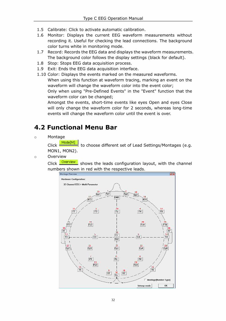
o Overview
Click shows the leads configuration layout, with the channel
numbers shown in red with the respective leads.
Type C EEG Operation Manual
33
Fig. 4-2 Overview
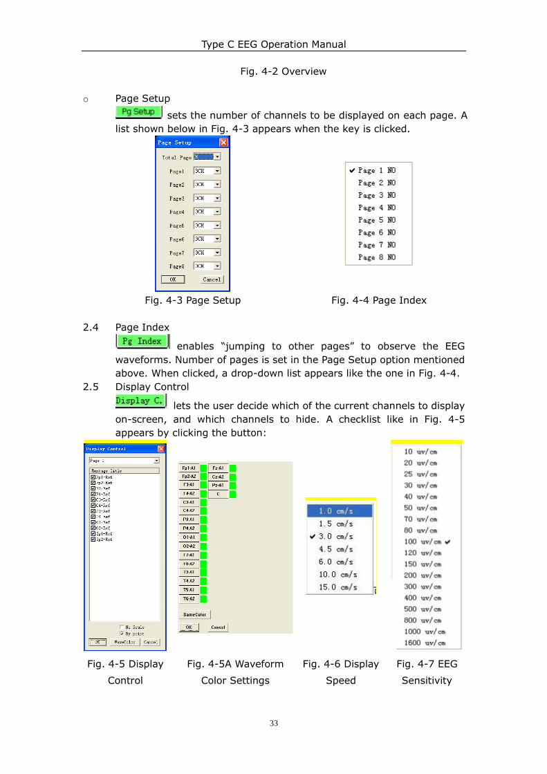
o Page Setup
sets the number of channels to be displayed on each page. A
list shown below in Fig. 4-3 appears when the key is clicked.
Fig. 4-3 Page Setup Fig. 4-4 Page Index
2.4 Page Index
enables “jumping to other pages” to observe the EEG
waveforms. Number of pages is set in the Page Setup option mentioned
above. When clicked, a drop-down list appears like the one in Fig. 4-4.
2.5 Display Control
lets the user decide which of the current channels to display
on-screen, and which channels to hide. A checklist like in Fig. 4-5
appears by clicking the button:
Fig. 4-5 Display
Control
Fig. 4-5A Waveform
Color Settings
Fig. 4-6 Display
Speed
Fig. 4-7 EEG
Sensitivity
Type C EEG Operation Manual
34
2.5.1 For example, uncheck the box for , and the O2-Ref channel will
be removed from the waveform display.
2.5.2 Check “No Scale” to remove the time scale display at the bottom of the
waveform interface; also, check “By Point” to improve the displaying
sample rate of the waveforms acquisition at reduced smoothness.
2.6 Choose “Wavecolor” to change the color of waveform (See Fig. 4-5A).
User can change the wave color of a channel by clicking on the channel
name and selecting a color. User can also change the color of all channels
by clicking “SameColor”. Click “OK” afterwards to save the color changes
and return to the acquisition interface, or click “Cancel” to discard all
color changes before exiting.
2.7 Speed
Click to choose a different waveform display speed. The display
rate is measured in the unit of cm/s (See Fig. 4-6). We usually choose
3.0cm/s.
2.8 EEG Sensitivity
The control adjusts the vertical scales of the EEG waveforms in
μV/cm units (See Fig. 4-7). We usually choose 100uv/cm or 80uv/cm.
2.9 Low Pass & High Pass
Filter controls to block out external noise interference. Low pass filter
range: None, 5Hz, 10Hz, 15Hz, 20Hz, 30Hz, 40Hz, 45Hz, 60Hz; High
pass filter range: None, 0.01s, 0.02s, 0.03s, 0.1s, 0.2s, 0.3s, 1s, 2s, 3s.
2.10 Notch
This option is to set the EEG notch for blocking out power line
interference. For some countries, the EEG notch is 50Hz and for the
others, 60Hz.
2.11 PSG Parameter
This function is not available for Type-C EEG System.
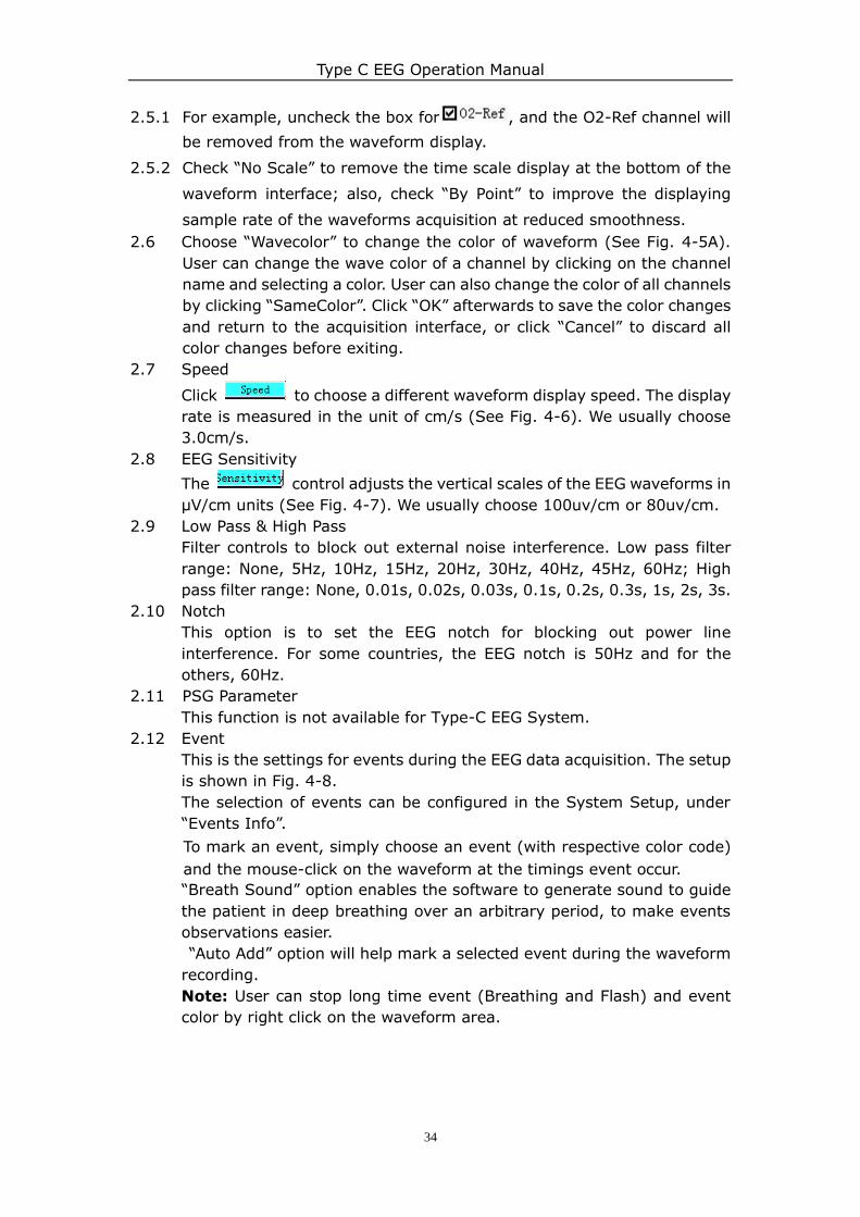
2.12 Event
This is the settings for events during the EEG data acquisition. The setup
is shown in Fig. 4-8.
The selection of events can be configured in the System Setup, under
“Events Info”.
To mark an event, simply choose an event (with respective color code)
and the mouse-click on the waveform at the timings event occur.
“Breath Sound” option enables the software to generate sound to guide
the patient in deep breathing over an arbitrary period, to make events
observations easier.
“Auto Add” option will help mark a selected event during the waveform
recording.
Note: User can stop long time event (Breathing and Flash) and event
color by right click on the waveform area.
Type C EEG Operation Manual
35
2.13 Stimulation Setup
For EEG configurations with stimulators, is used to generate
the stimulation for data acquisition. Fig. 4-9 shows the setup interface.
2.12.1 Deep Breath: Set the breath frequency and duration for “Breath Sound”
option in the Event settings. Inhale percent refers to the time interval
between the sounds of inspiration (breathing in) and expiration
(breathing out).
2.12.2 Flash stimulation: This requires the photic stimulator connected to the
system to work. The flash stimulation can be programmed to run up to 10
cycles with 5 phases at varying frequency, duration and time intervals.
Up to 10 stimulation programs can be stored for future examinations.
The following are the steps to use the flash stimulation feature:
Click on to choose the stimulation plan to use or edit;
Save plan: Click this button to save the currently set plan;
Cycle Index: Click to choose how many cycles will the stimulation last.
Phase: Displays detailed information of each stimulation phase.
Stimulate Freq: User can set the stimulation frequency of each phase
from 1Hz to 30Hz.
Stimulate Time: User can set the stimulation time of each phase from 5s
to 60s.
Time interval: User can set the time interval between each phase.
OK: Click this to save the changes and close the window.
Default: Reset the parameters to system default values.
Cancel: Click this to close window without saving the changes.
Fig. 4-8 Event Settings
Fig. 4-9 Stimulation Setup
Fig. 4-8A Deep Breathing
Options
Type C EEG Operation Manual
36
2.13 Video
If a video is installed to the system, this can be used to toggle the video
display on screen. Note: It is recommended to set the video compressor
setting to DivX MPEG4 Fast-Motion for optimum video performance.
2.14 Adjusting
This function is a test function used on the EEG amplifier. It should only
be operated under the guidance of technical personnel.
2.15 Case info
Check or edit the current patient related information.
2.16 Brain Ten.
This toggles the interface for brain trend analysis. Refer to Playback and
Analysis in Chapter 5 for details.
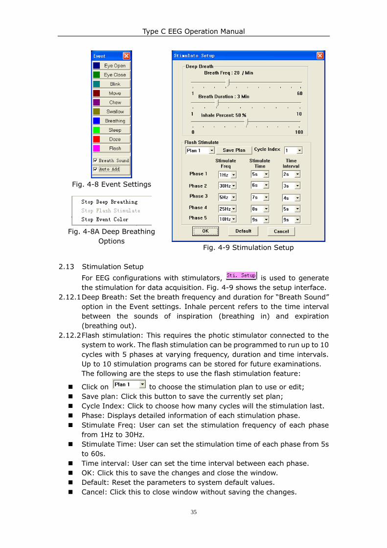
2.17 Lens PAN controller (PTZ Control)
This opens the control interface for Lens PAN Controller of the video
camera system, as shown in Fig. 4-10.
Fig. 4-10 Lens PAN controller
Type C EEG Operation Manual
37
Chapter 5 Playback and Analysis
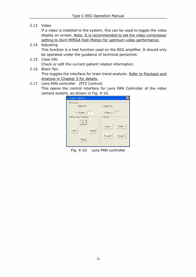
5.1 Playback
From the main interface, select the case to be analyzed from the case list and
then click "Play" on the toolbar to enter the playback and analysis interface.
Fig. 5-1 Playback Interface
1.1 Information bar:
The information bar at the top screen displays the patient name and various
parameters (sensitivity, display speed, filter status) of the waveforms
displayed on screen.
1.2 Waveform Display Area: Displays the waveforms measured and recorded.
1.3 Functional Button Area 1:
“Mode”, “Overview”, “Pg Setup”, “Pg Index”, “Speed”, “Sensitivity”, “L-Pass”,
“High Pass”, “EEG Notch”, "Sleep Para.", “Video” and “Case Information”
works just like the ones in the acquisition phase.
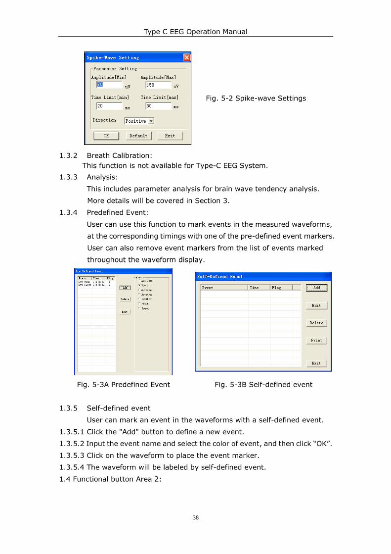
1.3.1 Spike Wave Analysis:
This function uses autonomic analysis method to detect all the spike
waves that are measured during the data acquisition phase. All the
spike waves will be compiled into a list.
Note: As autonomic analysis is mechanical method, much external
interference will also be recognized as spike waves, so the analysis
report is for reference only, and the doctor need to give medical
judgment based on his understanding of the measured results.
Type C EEG Operation Manual
38
Fig. 5-2 Spike-wave Settings
1.3.2 Breath Calibration:
This function is not available for Type-C EEG System.
1.3.3 Analysis:
This includes parameter analysis for brain wave tendency analysis.
More details will be covered in Section 3.
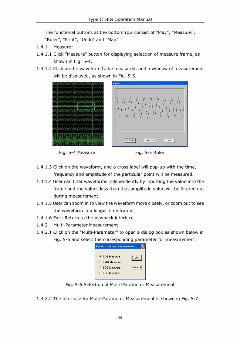
1.3.4 Predefined Event:
User can use this function to mark events in the measured waveforms,
at the corresponding timings with one of the pre-defined event markers.
User can also remove event markers from the list of events marked
throughout the waveform display.
Fig. 5-3A Predefined Event Fig. 5-3B Self-defined event
1.3.5 Self-defined event
User can mark an event in the waveforms with a self-defined event.
1.3.5.1 Click the "Add" button to define a new event.
1.3.5.2 Input the event name and select the color of event, and then click “OK”.
1.3.5.3 Click on the waveform to place the event marker.
1.3.5.4 The waveform will be labeled by self-defined event.
1.4 Functional button Area 2:
Type C EEG Operation Manual
39
The functional buttons at the bottom row consist of “Play”, “Measure”,
“Ruler”, “Print”, “Undo” and “Map”.
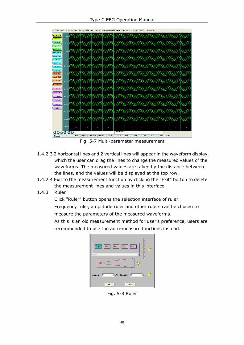
1.4.1 Measure:
1.4.1.1 Click "Measure" button for displaying selection of measure frame, as
shown in Fig. 5-4.
1.4.1.2 Click on the waveform to be measured, and a window of measurement
will be displayed, as shown in Fig. 5-5.
Fig. 5-4 Measure Fig. 5-5 Ruler
1.4.1.3 Click on the waveform, and a cross label will pop-up with the time,
frequency and amplitude of the particular point will be measured.
1.4.1.4 User can filter waveforms independently by inputting the value into the
frame and the values less than that amplitude value will be filtered out
during measurement.
1.4.1.5 User can zoom in to view the waveform more closely, or zoom out to see
the waveform in a longer time frame.
1.4.1.6 Exit: Return to the playback interface.
1.4.2 Multi-Parameter Measurement
1.4.2.1 Click on the "Multi-Parameter" to open a dialog box as shown below in
Fig. 5-6 and select the corresponding parameter for measurement.
Fig. 5-6 Selection of Multi-Parameter Measurement
1.4.2.2 The interface for Multi-Parameter Measurement is shown in Fig. 5-7.
Type C EEG Operation Manual
40
Fig. 5-7 Multi-parameter measurement
1.4.2.3 2 horizontal lines and 2 vertical lines will appear in the waveform display,
which the user can drag the lines to change the measured values of the
waveforms. The measured values are taken by the distance between
the lines, and the values will be displayed at the top row.
1.4.2.4 Exit to the measurement function by clicking the "Exit" button to delete
the measurement lines and values in this interface.
1.4.3 Ruler
Click "Ruler" button opens the selection interface of ruler.
Frequency ruler, amplitude ruler and other rulers can be chosen to
measure the parameters of the measured waveforms.
As this is an old measurement method for user‟s preference, users are
recommended to use the auto-measure functions instead.
Fig. 5-8 Ruler
Type C EEG Operation Manual
41
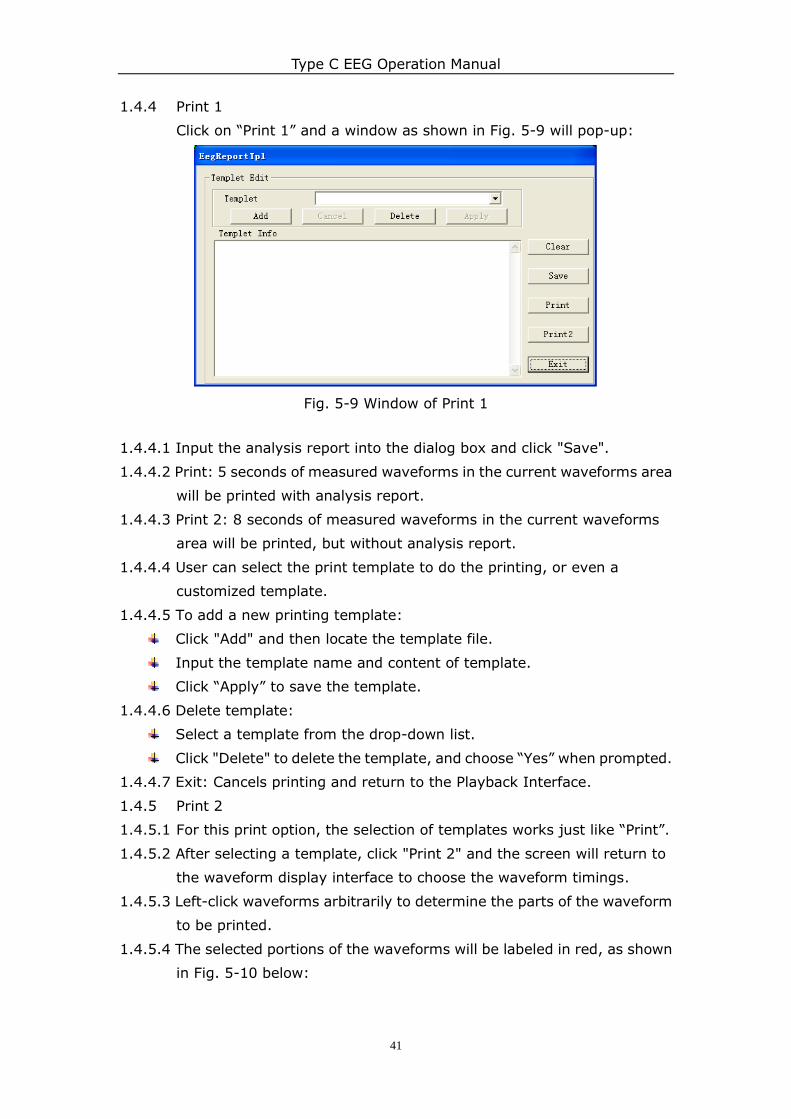
1.4.4 Print 1
Click on “Print 1” and a window as shown in Fig. 5-9 will pop-up:
Fig. 5-9 Window of Print 1
1.4.4.1 Input the analysis report into the dialog box and click "Save".
1.4.4.2 Print: 5 seconds of measured waveforms in the current waveforms area
will be printed with analysis report.
1.4.4.3 Print 2: 8 seconds of measured waveforms in the current waveforms
area will be printed, but without analysis report.
1.4.4.4 User can select the print template to do the printing, or even a
customized template.
1.4.4.5 To add a new printing template:
Click "Add" and then locate the template file.
Input the template name and content of template.
Click “Apply” to save the template.
1.4.4.6 Delete template:
Select a template from the drop-down list.
Click "Delete" to delete the template, and choose “Yes” when prompted.
1.4.4.7 Exit: Cancels printing and return to the Playback Interface.
1.4.5 Print 2
1.4.5.1 For this print option, the selection of templates works just like “Print”.
1.4.5.2 After selecting a template, click "Print 2" and the screen will return to
the waveform display interface to choose the waveform timings.
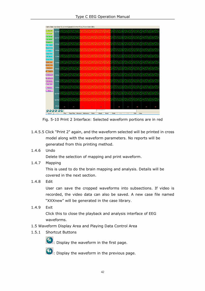
1.4.5.3 Left-click waveforms arbitrarily to determine the parts of the waveform
to be printed.
1.4.5.4 The selected portions of the waveforms will be labeled in red, as shown
in Fig. 5-10 below:
Type C EEG Operation Manual
42
Fig. 5-10 Print 2 Interface: Selected waveform portions are in red
1.4.5.5 Click "Print 2" again, and the waveform selected will be printed in cross
model along with the waveform parameters. No reports will be
generated from this printing method.
1.4.6 Undo
Delete the selection of mapping and print waveform.
1.4.7 Mapping
This is used to do the brain mapping and analysis. Details will be
covered in the next section.
1.4.8 Edit
User can save the cropped waveforms into subsections. If video is
recorded, the video data can also be saved. A new case file named
“XXXnew” will be generated in the case library.
1.4.9 Exit
Click this to close the playback and analysis interface of EEG
waveforms.
1.5 Waveform Display Area and Playing Data Control Area
1.5.1 Shortcut Buttons
: Display the waveform in the first page.
: Display the waveform in the previous page.
Type C EEG Operation Manual
43
: Display the waveform in the next page.
: Display the waveform in the last page.
: Display the waveform in last second.
: Display the waveform in next second.
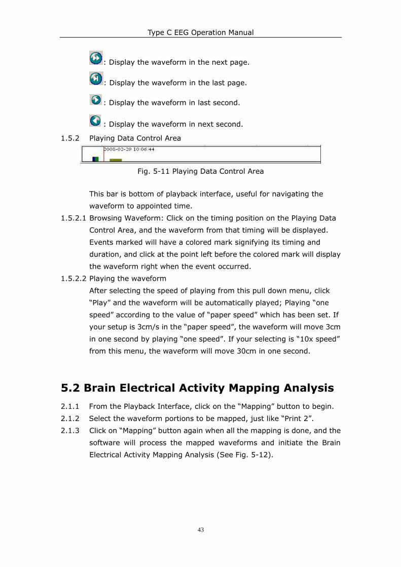
1.5.2 Playing Data Control Area
Fig. 5-11 Playing Data Control Area
This bar is bottom of playback interface, useful for navigating the
waveform to appointed time.
1.5.2.1 Browsing Waveform: Click on the timing position on the Playing Data
Control Area, and the waveform from that timing will be displayed.
Events marked will have a colored mark signifying its timing and
duration, and click at the point left before the colored mark will display
the waveform right when the event occurred.
1.5.2.2 Playing the waveform
After selecting the speed of playing from this pull down menu, click
“Play” and the waveform will be automatically played; Playing “one
speed” according to the value of “paper speed” which has been set. If
your setup is 3cm/s in the “paper speed”, the waveform will move 3cm
in one second by playing “one speed”. If your selecting is “10x speed”
from this menu, the waveform will move 30cm in one second.
5.2 Brain Electrical Activity Mapping Analysis
2.1.1 From the Playback Interface, click on the “Mapping” button to begin.
2.1.2 Select the waveform portions to be mapped, just like “Print 2”.
2.1.3 Click on “Mapping” button again when all the mapping is done, and the
software will process the mapped waveforms and initiate the Brain
Electrical Activity Mapping Analysis (See Fig. 5-12).
Type C EEG Operation Manual
44
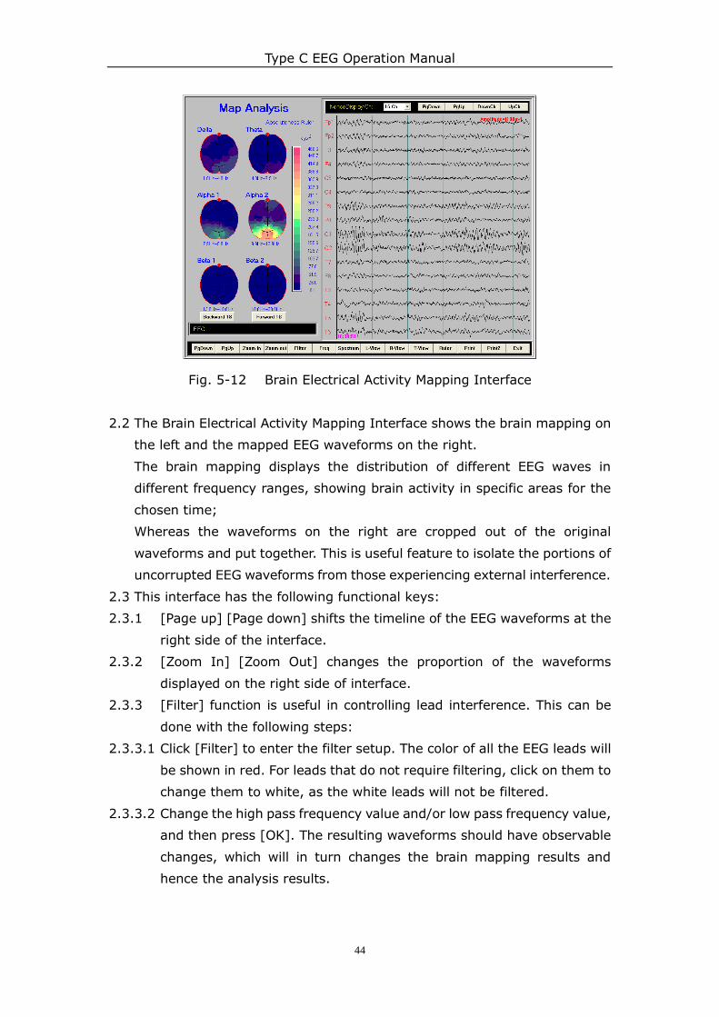
Fig. 5-12 Brain Electrical Activity Mapping Interface
2.2 The Brain Electrical Activity Mapping Interface shows the brain mapping on
the left and the mapped EEG waveforms on the right.
The brain mapping displays the distribution of different EEG waves in
different frequency ranges, showing brain activity in specific areas for the
chosen time;
Whereas the waveforms on the right are cropped out of the original
waveforms and put together. This is useful feature to isolate the portions of
uncorrupted EEG waveforms from those experiencing external interference.
2.3 This interface has the following functional keys:
2.3.1 [Page up] [Page down] shifts the timeline of the EEG waveforms at the
right side of the interface.
2.3.2 [Zoom In] [Zoom Out] changes the proportion of the waveforms
displayed on the right side of interface.
2.3.3 [Filter] function is useful in controlling lead interference. This can be
done with the following steps:
2.3.3.1 Click [Filter] to enter the filter setup. The color of all the EEG leads will
be shown in red. For leads that do not require filtering, click on them to
change them to white, as the white leads will not be filtered.
2.3.3.2 Change the high pass frequency value and/or low pass frequency value,
and then press [OK]. The resulting waveforms should have observable
changes, which will in turn changes the brain mapping results and
hence the analysis results.
Type C EEG Operation Manual
45
Fig. 5-13 Mapping Filter Interface
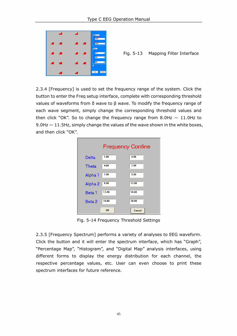
2.3.4 [Frequency] is used to set the frequency range of the system. Click the
button to enter the Freq setup interface, complete with corresponding threshold
values of waveforms from δ wave to β wave. To modify the frequency range of
each wave segment, simply change the corresponding threshold values and
then click “OK”. So to change the frequency range from 8.0Hz — 11.0Hz to
9.0Hz — 11.5Hz, simply change the values of the wave shown in the white boxes,
and then click “OK”.
Fig. 5-14 Frequency Threshold Settings
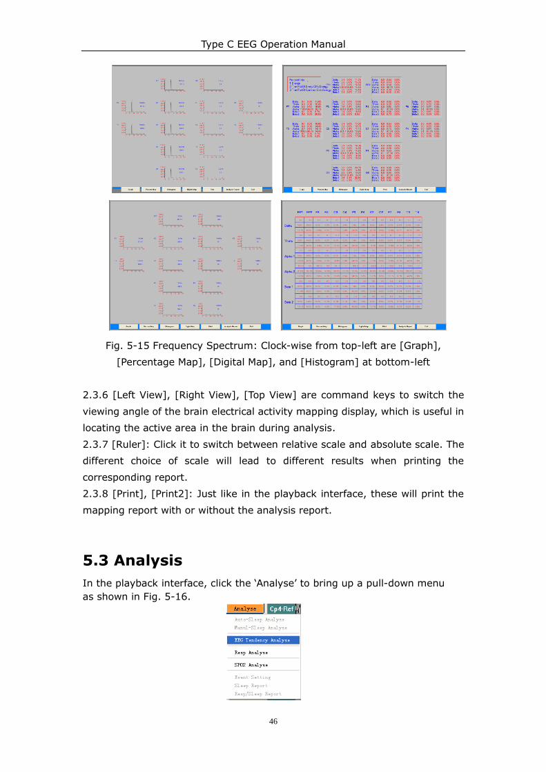
2.3.5 [Frequency Spectrum] performs a variety of analyses to EEG waveform.
Click the button and it will enter the spectrum interface, which has “Graph”,
“Percentage Map”, “Histogram”, and “Digital Map” analysis interfaces, using
different forms to display the energy distribution for each channel, the
respective percentage values, etc. User can even choose to print these
spectrum interfaces for future reference.
Type C EEG Operation Manual
46
Fig. 5-15 Frequency Spectrum: Clock-wise from top-left are [Graph],
[Percentage Map], [Digital Map], and [Histogram] at bottom-left
2.3.6 [Left View], [Right View], [Top View] are command keys to switch the
viewing angle of the brain electrical activity mapping display, which is useful in
locating the active area in the brain during analysis.
2.3.7 [Ruler]: Click it to switch between relative scale and absolute scale. The
different choice of scale will lead to different results when printing the
corresponding report.
2.3.8 [Print], [Print2]: Just like in the playback interface, these will print the
mapping report with or without the analysis report.
5.3 Analysis
In the playback interface, click the „Analyse‟ to bring up a pull-down menu
as shown in Fig. 5-16.
Type C EEG Operation Manual
47
Fig. 5-16 Analysis Menus
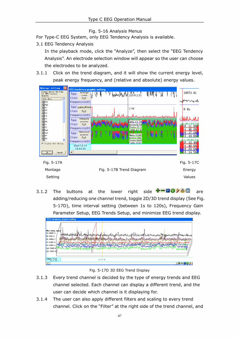
For Type-C EEG System, only EEG Tendency Analysis is available.
3.1 EEG Tendency Analysis
In the playback mode, click the “Analyze”, then select the “EEG Tendency
Analysis”. An electrode selection window will appear so the user can choose
the electrodes to be analyzed.
3.1.1 Click on the trend diagram, and it will show the current energy level,
peak energy frequency, and (relative and absolute) energy values.
Fig. 5-17A
Montage
Setting
Fig. 5-17B Trend Diagram
Fig. 5-17C
Energy
Values
3.1.2 The buttons at the lower right side are
adding/reducing one channel trend, toggle 2D/3D trend display (See Fig.
5-17D), time interval setting (between 1s to 120s), Frequency Gain
Parameter Setup, EEG Trends Setup, and minimize EEG trend display.
Fig. 5-17D 3D EEG Trend Display
3.1.3 Every trend channel is decided by the type of energy trends and EEG
channel selected. Each channel can display a different trend, and the
user can decide which channel is it displaying for.
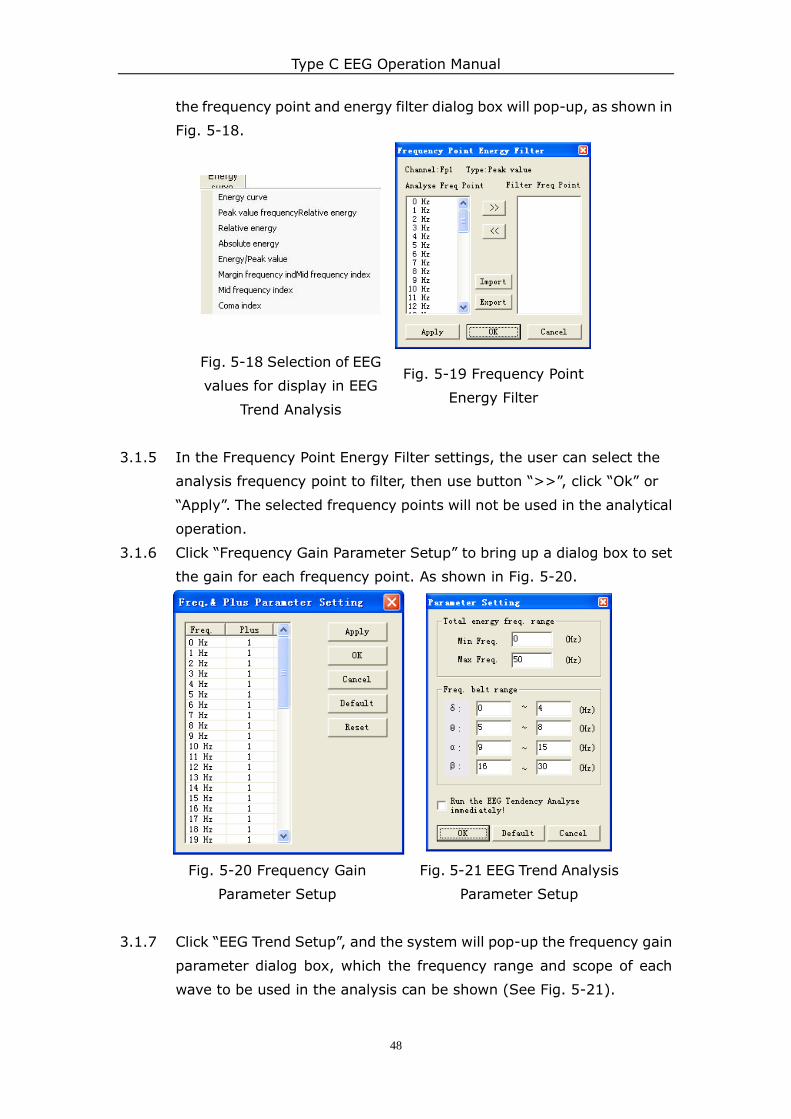
3.1.4 The user can also apply different filters and scaling to every trend
channel. Click on the “Filter” at the right side of the trend channel, and
Type C EEG Operation Manual
48
the frequency point and energy filter dialog box will pop-up, as shown in
Fig. 5-18.
Fig. 5-18 Selection of EEG
values for display in EEG
Trend Analysis
Fig. 5-19 Frequency Point
Energy Filter
3.1.5 In the Frequency Point Energy Filter settings, the user can select the
analysis frequency point to filter, then use button “>>”, click “Ok” or
“Apply”. The selected frequency points will not be used in the analytical
operation.
3.1.6 Click “Frequency Gain Parameter Setup” to bring up a dialog box to set
the gain for each frequency point. As shown in Fig. 5-20.
Fig. 5-20 Frequency Gain
Parameter Setup
Fig. 5-21 EEG Trend Analysis
Parameter Setup
3.1.7 Click “EEG Trend Setup”, and the system will pop-up the frequency gain
parameter dialog box, which the frequency range and scope of each
wave to be used in the analysis can be shown (See Fig. 5-21).
Type C EEG Operation Manual
49
Chapter 6 Important Safety
Information
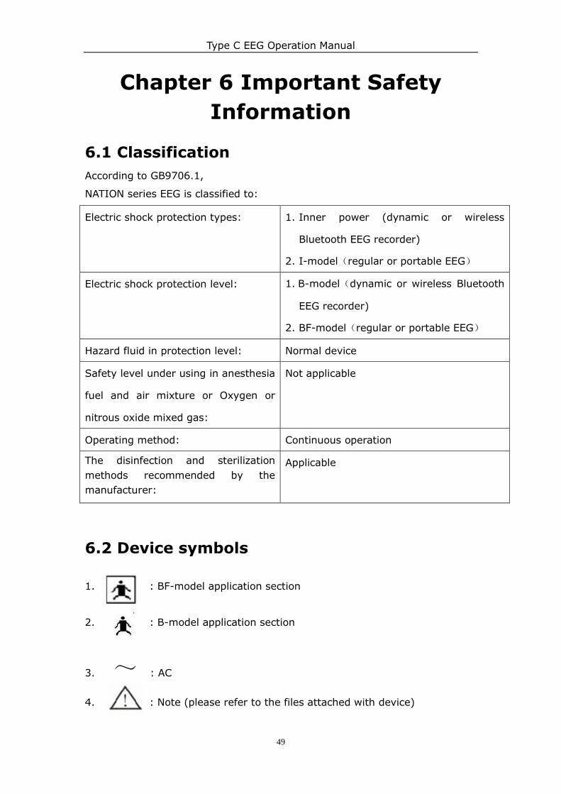
6.1 Classification
According to GB9706.1,
NATION series EEG is classified to:
Electric shock protection types: 1. Inner power (dynamic or wireless
Bluetooth EEG recorder)
2. I-model(regular or portable EEG)
Electric shock protection level: 1. B-model(dynamic or wireless Bluetooth
EEG recorder)
2. BF-model(regular or portable EEG)
Hazard fluid in protection level: Normal device
Safety level under using in anesthesia
fuel and air mixture or Oxygen or
nitrous oxide mixed gas:
Not applicable
Operating method: Continuous operation
The disinfection and sterilization
methods recommended by the
manufacturer:
Applicable
6.2 Device symbols
1. : BF-model application section
2. : B-model application section
3. ~ : AC
4. : Note (please refer to the files attached with device)
Type C EEG Operation Manual
50
Chapter 7 Maintenance &
Servicing This chapter is about the correct way to maintain the equipment in good
condition for the maximum duration, and solutions to problems that keep the
equipment from working properly.
Device maintenance inspection does not include the internal structure of the
apparatus, which can be carried out only by technicians or operators.
In view of the security of the apparatus and the requirements of access, internal
maintenance and testing equipment must be done by the authorized service
personnel. When the equipment is not working normally, it should be clearly
marked to avoid working under abnormal conditions.
Maintenance of equipment includes visual inspection, periodic cleaning and
system self-check routine. The following describes a simple run-through of the
basic maintenance procedures.
7.1 Cleaning and Disinfection
Warning! Disconnect the power supply of the equipment before cleaning or
disinfecting it to prevent electrocution.
1. Outer surface (master controller unit, EEG amplifier, ERP stimulators, video
recording system, printer and host computer, etc.):
Outer surface of equipment should be cleaned regularly with non-depilate
soft cloth soaked wet in mild, diluted soapy water.
To avoid damaging the equipment, user is advised to:
Always clean equipment according to the manufacturer's recommended
dilution and cleaning method.
Always wipe the equipment with a clean and dry cloth after cleaning.
Never use cleaning material with wax to clean the equipment.
Never splash or spray water or any cleaning solution onto the
equipment, or allow the liquid to influx to the back of the switch or the
connectors or any air vents of the equipment.
Never use the following agents for cleaning of EEG equipment: Acetone,
ketone, alcoholic cleansers and any abrasive cleaning agents or
solutions.
Failure to conform to the cleaning recommendations above may cause
dissolving or distortion to the outer coating of the equipment, corrosion
to the characters on the labels, or even lead to equipment failure.
2. The Display Screen
!
Type C EEG Operation Manual
51
Please keep in mind that the screen should be cleaned with clean soft fabric
cloth that is wet by glass cleaning detergent. Do not spray the detergent
onto the screen directly, and do not use alcohol or any medical disinfectant
to do the cleaning.
3. Cleaning of EEG Accessories
a. The Lead Wires for Connecting Electrodes
Note:
Patient lead wires can be cleaned using warm, damp cloth with mild soap
suds, or by using isopropyl alcohol.
Do not use acetone or ketone solutions to do the cleaning; do not use
high-pressure steam sterilization or any autoclave cleaning agent.
Do not soak the patient lead wires.
b. Earphones
Note:
Before and after using earphones, the part of the earphones in physical contact
with the ear should be cleaned with 75% medicinal alcohol.
Earphones can be cleaned using warm, damp cloth and mild soapy water, or
by using isopropyl alcohol.
Do not use acetone or ketone solutions to do the cleaning; do not use
high-pressure steam sterilization or any autoclave cleaning agent.
Do not soak the earphones.
c. Electrodes
Remove the conductive paste film from the surface of the electrode plate
after use.
Clean the electrode plates with absorbent cotton cloth with alcohol, and
then make it dry.
Warning: Do not use any abrasive or grinding materials to clean the
electrodes, for any scrape on the electrode plate may lead to inaccurate
readings in future use.
7.2 Appearance Inspections
Note:
Inspect the external parts of equipment periodically. Only authorized service
personnel can replace the damaged parts.
1. Each time after use, clean the patient lead wires and equipment before
performing appearance inspection to detect damage of components in time.
Type C EEG Operation Manual
52
2. Service and maintenance procedures
a. The product only requires minimal maintenance due to the high level of
production process made during the product manufacturing.
b. The replacement fuse must be same as the regulated type. (T2A250v)
c. It is recommended that users maintain and calibrate the device
periodically, at least once a year or whenever any problem is suspected.
The device should be returned to the supplier if any complex detection
and calibration is necessary.
d. Circuit diagrams of the equipment, the accessory parts list and other
technical information are only provided for authorized service personnel
in servicing the equipment.
e. When the power indicator of the amplifier turns orange and begins
flashing, the battery is running out, so it is time to recharge the
amplifier with the charger. Under normal operation, the power light is
always green.
Note: Do not use the equipment to test when charging.
Warning:
The warranty is valid as long as the accessories used are provided by the
supplier or purchased from third party sources approved by the supplier.
If isolation transformer is used, the total power consumption of the display,
printer and host computer should not be larger than the output power of the
isolation transformer.
7.3 Troubleshooting
The functional changes listed below are all the possible problems that may
happen after using the instrument for some time.
1. The keys are not working
There are 6 function keys on the EEG amplifier, where some of the keys may
be invalid or with poor contact. For this problem, please contact the supplier
for repair according to the terms of service.
2. The computer system cannot identify the EEG instrument.
There are a few reasons that cause this problem to occur:
1) The driver programs may be lost due to computer system error. The user
can recover the driver programs from the installation CD disk provided

Type C EEG Operation Manual
53
with the EEG system package if you are sure that the computer is not
infected by viruses or malware and the system is not damaged;
2) The amplifier hardware failure may have caused the installation to fail. The
user may confirm whether the issue is caused by the amplifier by following
the operations mentioned in 1). If the hardware is not recognized by the
computer despite having the driver programs installed, then hardware
failure can be confirmed. Please return the amplifier to the supplier for
servicing.
3. When the user is running an EEG examination, the waveform of one or
several channels are straight line or there is significant interference in the
signal output.
The possible causes to this problem are:
1) The quality of the electrode wires deteriorated due to wear and tear over a
long time of use, so normal waveform data cannot be collected. The
electrode wires are consumable materials with life cycle of one year in
general. If this is the problem, user is recommended to purchase for new
electrode lines from the supplier.
2) Amplifier failure causes the waveform output to be straight line or have
significant interference. The user may exchange the electrode wires of the
channels with output issues with the normal ones to confirm whether it is
caused by the electrode wires or the faulty in the amplifier. If amplifier
failure is confirmed to be the cause, then please return the amplifier to the
supplier for servicing.
4. The rechargeable battery may not work properly after it is used for a long
time, or due to the equipment not being used for a long time. In either case,
the battery will last shorter than expected duration. This can also happen
when the battery is damaged due to external factors.
The battery should be replaced with a new battery from the supplier or any
sources recommended by the supplier. The old battery should be disposed of
according to the local safety regulations.
7.4 Transportation and Storage Conditions
a) Environment temperature range: -40°C~55°C;
b) Relative humidity range: ≤95%;
c) Atmospheric pressure range: 960hPa~1060hPa.

Type C EEG Operation Manual
54
Appendix A: Manufacturer Information
Company Name: NCC Medical Co., Ltd
Business Registration Number: 310114000270268
Medical Instrument Manufacturing License Number: The number is 20030710
from Shanghai Food Drug Administration.
Organization Code: 63080226-X
Company Address: No.68, Nansha Road, Minhang District, 200245 Shanghai,
P.R.China
Contact information:
Technical Engineer
Speed Su Jeter Xu
Email: [email protected] Email: [email protected]
Mobil: +86-18821108071 Mobil: +86-18821107327
Appendix B: Power Supply & Battery
Operation
Please check whether the voltage of the power corresponds to the value written
on the power label.
To ensure safe and reliable battery operation over long term, the following
operation procedures need to be practiced:
◇ The actual lifetime of batteries may differ from stated lifetime, depending on
the battery manufacturers, room temperature, frequency of use and
frequency of recharging.
◇ In the events of being opened or burned, or incorrect installation, the battery
may explode or leak and end up causing injuries to the user.
◇ The battery should be replaced immediately when the following happens:
Abnormal battery performance such as low battery durability after
being fully recharged.
The lifetime of the battery is stated to be 2 years; even then the battery
can still be recharged for future use.
Appendix C: Electromagnetic
Compatibility
This equipment has not been implemented with YY0505-2005 EMC testing
according to state regulations. However, electromagnetic environment
Type C EEG Operation Manual
55
exceeding YY0505 specified parameters will seriously interfere with the
equipment and result in the device not achieving its intended performance
levels. Therefore, electromagnetic effects in the test environment should be
avoided, identified and resolved before using the equipment.
Here below are some common sources of electromagnetic interference
and relevant solutions:
1. Strong electromagnetic interference from radio or cell phone:
This equipment and / or system can be installed in other locations. Emission
sources such as mobile phones should stay away from the equipment and /
or system, or be switched off during examinations.
2. Using AC power for the equipment and / or system, and radio interference
from other devices:
Confirm the source of interference and if possible, remove the interference
source. Otherwise, please adopt a different power supply.
3. Direct or indirect static electricity influence:
Before use, confirm that all operators and patients contacting the
equipment do not have direct or indirect static electricity by washing their
hands clean.
4. Interference from radio receivers, such as radio or television:
The device and / or system should be kept away as far as possible from the
radio receivers.
5. Lightning interference:
When lightning occurs near the equipment and / or system, it will cause
very high voltage surge to the device and / or system.
In this case, unplug the AC power line from device and / or system, and use
battery power or an uninterruptible power supply to operate the device and
/ or systems.
6. Usage with other devices:
When the device and / or system is positioned near or stacked with other
devices, the output of the devices and / or systems may interfere with each
other. Please confirm with the supplier in advance that the devices and / or
systems can be used together safely.
7. Use of non-specified accessories, transducer and / or cable:
If this device and / or system use non-specified accessories, transducer and
/ or cables, electromagnetic radiation will increase and reduce
electromagnetic immunity. Electromagnetic requirements of this equipment
and / or system are consistent with the specified configuration. The
equipment and / or systems should be used by the specified configuration.

NCC Medical Co., Ltd
Recommended