Proceedings of the International Association for Shell and Spatial Structures (IASS) Symposium 2009, ValenciaEvolution and Trends in Design, Analysis and Construction of Shell and Spatial Structures
28 September – 2 October 2009, Universidad Politecnica de Valencia, SpainAlberto DOMINGO and Carlos LAZARO (eds.)
Palacio de Comunicaciones – a single layer glass grid
shell over the courtyard of the future town hall of
Madrid
Mike SCHLAICH*, Uwe BURKHARDTa, Luis IRISARRIb,
Josu GOÑIb
*Professor at Technical University of Berlin, Germany
Director of Schlaich Bergermann und Partner, Berlin, Germany
Brunnenstr. 110c, 13355 Berlin, Germany
www.sbp.de
a Schlaich Bergermann und Partner, Structural Consulting Engineers, Berlin, Germany b Lanik, Special Structures, San Sebastian, Spain
Abstract
Madrid is moving its town hall into the renovated “Palacio de Comunicaciones”. A part of
this renovation was the covering of the courtyard with a lightweight glass roof to improve
its usability. The structure is a single layer grid shell with a surface area of about 3000 m2
and a main span of approx. 45 m what makes it to one of the widest spanning single layer
glass grid shells. The introduction of a horizontal cable net and a strong edge beam allows
real shell behavior with mainly membrane forces. This leads to minimum impact on the
historic building surrounding the roof since only vertical loads and some external horizontal
loads need to be introduced in the existing structure. The bars that form the triangular grid
shell are connected by bolted nodes. Two bolt layers assure high bending resistance and
lead to speedy erection without the need for prestressing. State-of-the-art CNC techniques
for preparing the nodes and bars allowed to achieve the precision needed for single-layer
grid shells. This paper describes the entire design process as well as the construction of the
roof starting with the competition, moving over to the form finding of the shell shape and a
description of the structural design and detailing.
Keywords: freeform, grid shell, single layer, form finding, non-linear analysis, glass
design, lightweight structure, CNC manufacture, erection process, historic structure.
1338
Proceedings of the International Association for Shell and Spatial Structures (IASS) Symposium 2009, ValenciaEvolution and Trends in Design, Analysis and Construction of Shell and Spatial Structures
1. Introduction
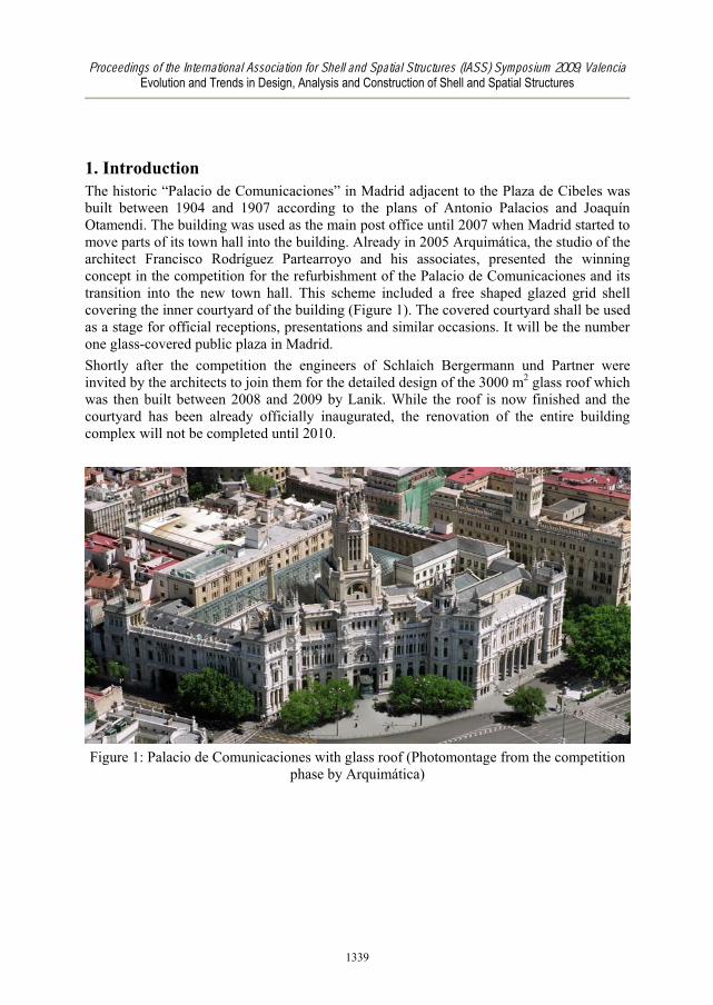
The historic “Palacio de Comunicaciones” in Madrid adjacent to the Plaza de Cibeles was
built between 1904 and 1907 according to the plans of Antonio Palacios and Joaquín
Otamendi. The building was used as the main post office until 2007 when Madrid started to
move parts of its town hall into the building. Already in 2005 Arquimática, the studio of the
architect Francisco Rodríguez Partearroyo and his associates, presented the winning
concept in the competition for the refurbishment of the Palacio de Comunicaciones and its
transition into the new town hall. This scheme included a free shaped glazed grid shell
covering the inner courtyard of the building (Figure 1). The covered courtyard shall be used
as a stage for official receptions, presentations and similar occasions. It will be the number
one glass-covered public plaza in Madrid.
Shortly after the competition the engineers of Schlaich Bergermann und Partner were
invited by the architects to join them for the detailed design of the 3000 m2 glass roof which
was then built between 2008 and 2009 by Lanik. While the roof is now finished and the
courtyard has been already officially inaugurated, the renovation of the entire building
complex will not be completed until 2010.
Figure 1: Palacio de Comunicaciones with glass roof (Photomontage from the competition
phase by Arquimática)
1339
Proceedings of the International Association for Shell and Spatial Structures (IASS) Symposium 2009, ValenciaEvolution and Trends in Design, Analysis and Construction of Shell and Spatial Structures
2. Conceptual design
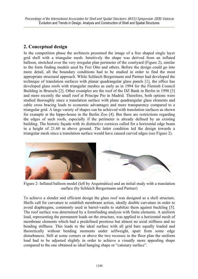
In the competition phase the architects presented the image of a free shaped single layer
grid shell with a triangular mesh. Intuitively the shape was derived from an inflated
balloon, stretched over the very irregular plan perimeter of the courtyard (Figure 2), similar
to the form finding models used by Frei Otto and others. Before the design could go into
more detail, all the boundary conditions had to be studied in order to find the most
appropriate structural approach. While Schlaich Bergermann und Partner had developed the
technique of translation surfaces with planar quadrangular glass panels [1], the office has
developed glass roofs with triangular meshes as early as in 1994 for the Flemish Council
Building in Brussels [2]. Other examples are the roof of the DZ Bank in Berlin in 1998 [3]
and more recently the small roof at Principe Pio in Madrid. Therefore, both options were
studied thoroughly since a translation surface with plane quadrangular glass elements and
cable cross bracing leads to economic advantages and more transparency compared to a
triangular grid. A large variety of shapes can be achieved with translation surfaces as shown
for example at the hippo-house in the Berlin Zoo [4]. But there are restrictions regarding
the edges of such roofs, especially if the perimeter is already defined by an existing
building. The historic façade with its distinctive cornices called for a horizontal edge beam
in a height of 21.60 m above ground. The latter condition led the design towards a
triangular mesh since a translation surface would have caused curved edges (see Figure 2).
Figure 2: Inflated balloon model (left by Arquimática) and an initial study with a translation
surface (by Schlaich Bergermann und Partner)
To achieve a slender and efficient design the glass roof was designed as a shell structure.
Shells call for curvature to establish membrane action, ideally double curvature in order to
avoid diaphragms, commonly used in barrel-vaults to stabilize them against buckling [5].
The roof surface was determined by a formfinding analysis with finite elements. A uniform
load, representing the permanent loads on the structure, was applied to a horizontal mesh of
membrane elements which had a predefined prestress but almost no axial stiffness and no
bending stiffness. This leads to the ideal surface with all grid bars equally loaded and
theoretically without bending moments under selfweight, apart from some edge
disturbances. Still at some corners or above the two recesses in the floor plan the uniform
load had to be adjusted slightly in order to achieve a visually more appealing shape
compared to the one obtained as ideal hanging shape or “catenary surface”.
1340
Proceedings of the International Association for Shell and Spatial Structures (IASS) Symposium 2009, ValenciaEvolution and Trends in Design, Analysis and Construction of Shell and Spatial Structures
This basically changes the uniform normal force distribution in the grid slightly and leads
to some bending moments which will be very small because of the short spans especially at
the recesses.
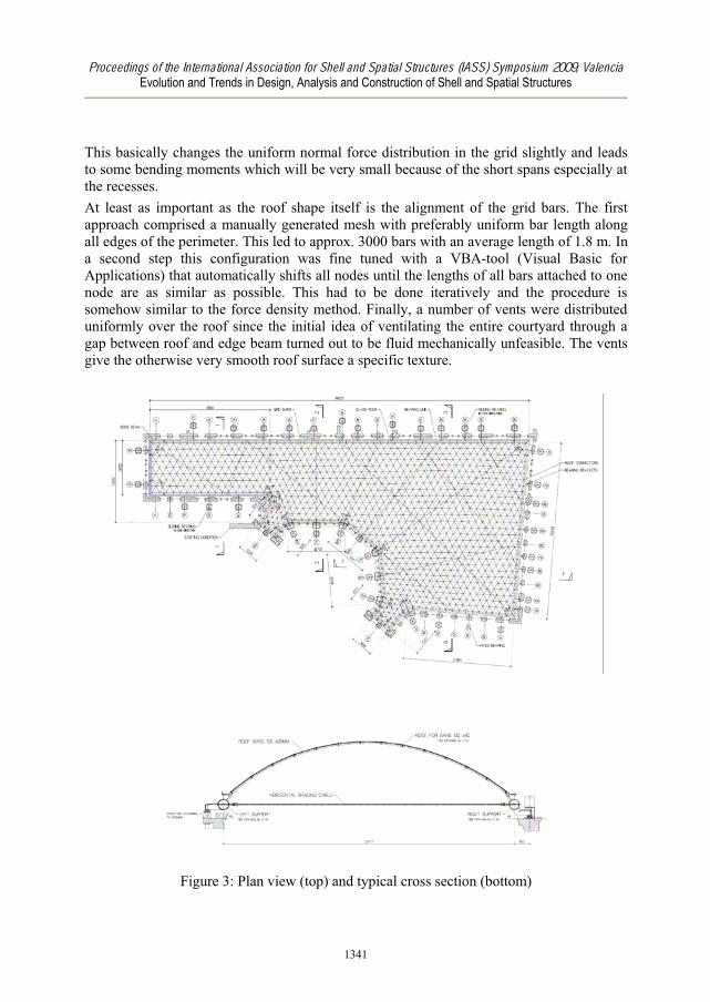
At least as important as the roof shape itself is the alignment of the grid bars. The first
approach comprised a manually generated mesh with preferably uniform bar length along
all edges of the perimeter. This led to approx. 3000 bars with an average length of 1.8 m. In
a second step this configuration was fine tuned with a VBA-tool (Visual Basic for
Applications) that automatically shifts all nodes until the lengths of all bars attached to one
node are as similar as possible. This had to be done iteratively and the procedure is
somehow similar to the force density method. Finally, a number of vents were distributed
uniformly over the roof since the initial idea of ventilating the entire courtyard through a
gap between roof and edge beam turned out to be fluid mechanically unfeasible. The vents
give the otherwise very smooth roof surface a specific texture.
Figure 3: Plan view (top) and typical cross section (bottom)
1341
Proceedings of the International Association for Shell and Spatial Structures (IASS) Symposium 2009, ValenciaEvolution and Trends in Design, Analysis and Construction of Shell and Spatial Structures
The entire roof is supported by the existing structure from the year 1907. While the load
bearing capacity for vertical downward loads is significant, it was not possible to introduce
any significant horizontal loads in the north, east and south wall. Also uplift would have
caused disproportional efforts in retrofitting the old structure. As mentioned above the roof
is acting as a shell that means it produces horizontal thrust along its lower edges. Since this
could not be borne by the surrounding structure a grid of horizontal cables (fully locked
cables with a diameter of 45 mm) was installed that balances this thrust between opposing
edges. In contrast to the rather regular mesh of the grid bars the cable net looks random on
first glance in order not to compete with the roof. Only the attentive viewer will notice that
all cables are pointing to two centre points far outside of the courtyard, an idea of the
architects to “keep some order in the chaos”. Structurally there is no justification in this
alignment.
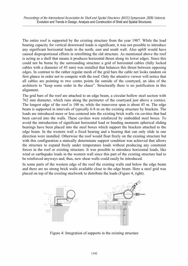
The grid bars of the roof are attached to an edge beam, a circular hollow steel section with
762 mm diameter, which runs along the perimeter of the courtyard just above a cornice.
The longest edge of the roof is 100 m, while the transverse span is about 45 m. The edge
beam is supported in intervals of typically 6-8 m on the existing structure by brackets. The
loads are introduced more or less centered into the existing brick walls via cavities that had
been carved into the walls. These cavities were reinforced by embedded steel boxes. To
avoid the introduction of significant horizontal load or bending moments spherical sliding
bearings have been placed into the steel boxes which support the brackets attached to the
edge beam. In the western wall a fixed bearing and a bearing that can only slide in one
direction were installed. Otherwise the roof would float freely on the existing structure but
with this configuration a statically determinate support condition was achieved that allows
the structure to expand freely under temperature loads without producing any constraint
forces in the roof or existing structure. It was possible to introduce horizontal loads, like
wind or earthquake loads in the western wall since this part of the existing structure had to
be reinforced anyways and, thus, new shear walls could easily be introduced.
In some parts of the western edge of the roof the existing walls end below the edge beam
and there are no strong brick walls available close to the edge beam. Here a steel grid was
placed on top of the existing steelwork to distribute the loads (Figure 4, right).
Figure 4: Integration of supports in the existing structure
1342
Proceedings of the International Association for Shell and Spatial Structures (IASS) Symposium 2009, ValenciaEvolution and Trends in Design, Analysis and Construction of Shell and Spatial Structures
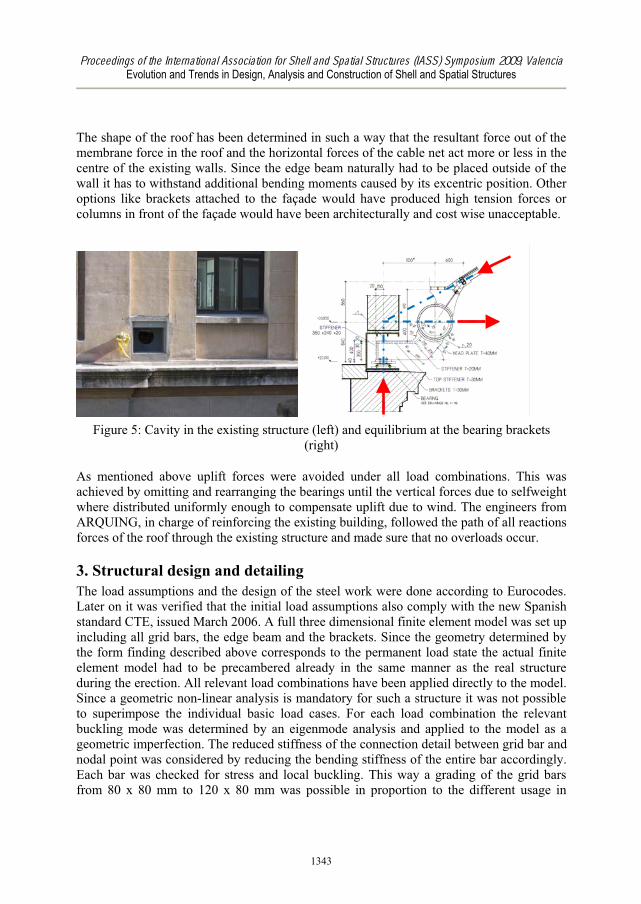
The shape of the roof has been determined in such a way that the resultant force out of the
membrane force in the roof and the horizontal forces of the cable net act more or less in the
centre of the existing walls. Since the edge beam naturally had to be placed outside of the
wall it has to withstand additional bending moments caused by its excentric position. Other
options like brackets attached to the façade would have produced high tension forces or
columns in front of the façade would have been architecturally and cost wise unacceptable.
Figure 5: Cavity in the existing structure (left) and equilibrium at the bearing brackets
(right)
As mentioned above uplift forces were avoided under all load combinations. This was
achieved by omitting and rearranging the bearings until the vertical forces due to selfweight
where distributed uniformly enough to compensate uplift due to wind. The engineers from
ARQUING, in charge of reinforcing the existing building, followed the path of all reactions
forces of the roof through the existing structure and made sure that no overloads occur.
3. Structural design and detailing
The load assumptions and the design of the steel work were done according to Eurocodes.
Later on it was verified that the initial load assumptions also comply with the new Spanish
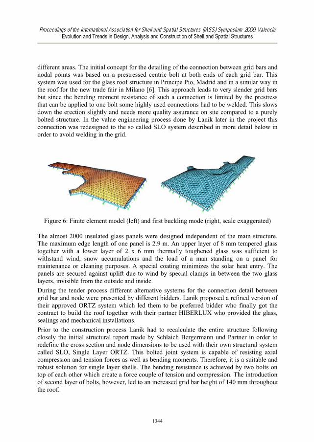
standard CTE, issued March 2006. A full three dimensional finite element model was set up
including all grid bars, the edge beam and the brackets. Since the geometry determined by
the form finding described above corresponds to the permanent load state the actual finite
element model had to be precambered already in the same manner as the real structure
during the erection. All relevant load combinations have been applied directly to the model.
Since a geometric non-linear analysis is mandatory for such a structure it was not possible
to superimpose the individual basic load cases. For each load combination the relevant
buckling mode was determined by an eigenmode analysis and applied to the model as a
geometric imperfection. The reduced stiffness of the connection detail between grid bar and
nodal point was considered by reducing the bending stiffness of the entire bar accordingly.
Each bar was checked for stress and local buckling. This way a grading of the grid bars
from 80 x 80 mm to 120 x 80 mm was possible in proportion to the different usage in
1343
Proceedings of the International Association for Shell and Spatial Structures (IASS) Symposium 2009, ValenciaEvolution and Trends in Design, Analysis and Construction of Shell and Spatial Structures
different areas. The initial concept for the detailing of the connection between grid bars and
nodal points was based on a prestressed centric bolt at both ends of each grid bar. This
system was used for the glass roof structure in Principe Pio, Madrid and in a similar way in
the roof for the new trade fair in Milano [6]. This approach leads to very slender grid bars
but since the bending moment resistance of such a connection is limited by the prestress
that can be applied to one bolt some highly used connections had to be welded. This slows
down the erection slightly and needs more quality assurance on site compared to a purely
bolted structure. In the value engineering process done by Lanik later in the project this
connection was redesigned to the so called SLO system described in more detail below in
order to avoid welding in the grid.
Figure 6: Finite element model (left) and first buckling mode (right, scale exaggerated)
The almost 2000 insulated glass panels were designed independent of the main structure.
The maximum edge length of one panel is 2.9 m. An upper layer of 8 mm tempered glass
together with a lower layer of 2 x 6 mm thermally toughened glass was sufficient to
withstand wind, snow accumulations and the load of a man standing on a panel for
maintenance or cleaning purposes. A special coating minimizes the solar heat entry. The
panels are secured against uplift due to wind by special clamps in between the two glass
layers, invisible from the outside and inside.
During the tender process different alternative systems for the connection detail between
grid bar and node were presented by different bidders. Lanik proposed a refined version of
their approved ORTZ system which led them to be preferred bidder who finally got the
contract to build the roof together with their partner HIBERLUX who provided the glass,
sealings and mechanical installations.
Prior to the construction process Lanik had to recalculate the entire structure following
closely the initial structural report made by Schlaich Bergermann und Partner in order to
redefine the cross section and node dimensions to be used with their own structural system
called SLO, Single Layer ORTZ. This bolted joint system is capable of resisting axial
compression and tension forces as well as bending moments. Therefore, it is a suitable and
robust solution for single layer shells. The bending resistance is achieved by two bolts on
top of each other which create a force couple of tension and compression. The introduction
of second layer of bolts, however, led to an increased grid bar height of 140 mm throughout
the roof.
1344
Proceedings of the International Association for Shell and Spatial Structures (IASS) Symposium 2009, ValenciaEvolution and Trends in Design, Analysis and Construction of Shell and Spatial Structures
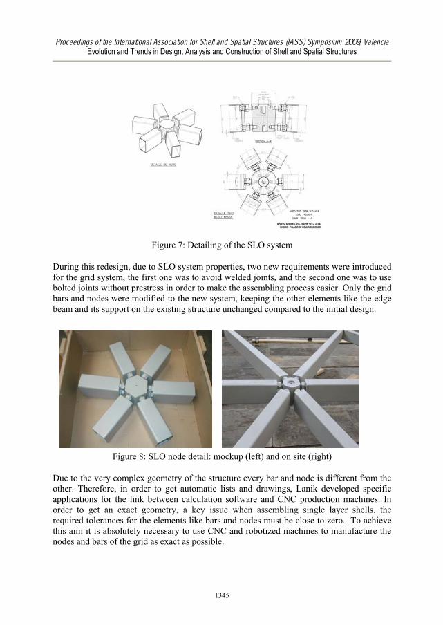
Figure 7: Detailing of the SLO system
During this redesign, due to SLO system properties, two new requirements were introduced
for the grid system, the first one was to avoid welded joints, and the second one was to use
bolted joints without prestress in order to make the assembling process easier. Only the grid
bars and nodes were modified to the new system, keeping the other elements like the edge
beam and its support on the existing structure unchanged compared to the initial design.
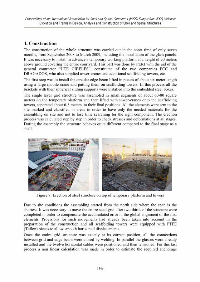
Figure 8: SLO node detail: mockup (left) and on site (right)
Due to the very complex geometry of the structure every bar and node is different from the
other. Therefore, in order to get automatic lists and drawings, Lanik developed specific
applications for the link between calculation software and CNC production machines. In
order to get an exact geometry, a key issue when assembling single layer shells, the
required tolerances for the elements like bars and nodes must be close to zero. To achieve
this aim it is absolutely necessary to use CNC and robotized machines to manufacture the
nodes and bars of the grid as exact as possible.
1345
Proceedings of the International Association for Shell and Spatial Structures (IASS) Symposium 2009, ValenciaEvolution and Trends in Design, Analysis and Construction of Shell and Spatial Structures
4. Construction
The construction of the whole structure was carried out in the short time of only seven
months, from September 2008 to March 2009, including the installation of the glass panels.
It was necessary to install in advance a temporary working platform at a height of 20 meters
above ground covering the entire courtyard. This part was done by PERI with the aid of the
general contractor “UTE CIBELES”, constituted of the two companies FCC and
DRAGADOS, who also supplied tower-cranes and additional scaffolding towers, etc.
The first step was to install the circular edge beam lifted in pieces of about six meter length
using a large mobile crane and putting them on scaffolding towers. In this process all the
brackets with their spherical sliding supports were installed into the embedded steel boxes.
The single layer grid structure was assembled in small segments of about 60-80 square
meters on the temporary platform and then lifted with tower-cranes onto the scaffolding
towers, separated about 6-8 meters, to their final positions. All the elements were sent to the
site marked and classified in areas in order to have only the needed materials for the
assembling on site and not to lose time searching for the right component. The erection
process was calculated step by step in order to check stresses and deformations at all stages.
During the assembly the structure behaves quite different compared to the final stage as a
shell.
Figure 9: Erection of steel structure on top of temporary platform and towers
Due to site conditions the assembling started from the north side where the span is the
shortest. It was necessary to move the entire steel grid after two thirds of the structure were
completed in order to compensate the accumulated error in the global alignment of the first
elements. Provisions for such movements had already been taken into account in the
preparation of the construction and all scaffolding towers were equipped with PTFE
(Teflon) pieces to allow smooth horizontal displacements.
Once the entire grid structure was exactly at its correct position, all the connections
between grid and edge beam were closed by welding. In parallel the glasses were already
installed and the twelve horizontal cables were positioned and then tensioned. For this last
process a non linear calculation was made in order to estimate the required anchorage
1346
Proceedings of the International Association for Shell and Spatial Structures (IASS) Symposium 2009, ValenciaEvolution and Trends in Design, Analysis and Construction of Shell and Spatial Structures
displacement required to achieve the predefined cable force for each cable. During the
cable stressing process the grid partially uplifted from the temporary scaffolding towers
while the edge beam was still fully supported. Finally all towers and the scaffolding
structure below the edge beam were lowered carefully following a calculated procedure.
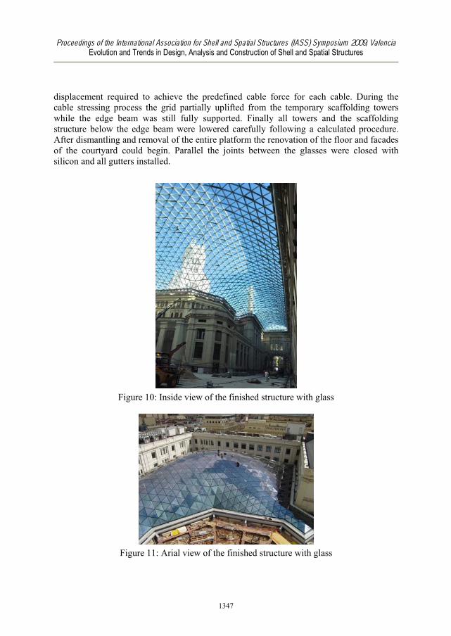
After dismantling and removal of the entire platform the renovation of the floor and facades
of the courtyard could begin. Parallel the joints between the glasses were closed with
silicon and all gutters installed.
Figure 10: Inside view of the finished structure with glass
Figure 11: Arial view of the finished structure with glass
1347
Proceedings of the International Association for Shell and Spatial Structures (IASS) Symposium 2009, ValenciaEvolution and Trends in Design, Analysis and Construction of Shell and Spatial Structures
5. Summary
Once more this roof shows that a design that follows the natural flow of forces can lead to a
lightweight, very elegant and still economic structure. It is typical for lightweight structures
that the high transparency in the surface has to be paid by strong abutments, in this case the
edge beam. Still, the entire structure is so light that it can easily be supported by a historic
building constructed over 100 years ago with only minor retrofit.
But not only the structural approach of following the flow of forces defines the quality of
such a structure. Also the alignment of the grid and the detailing of all connections can
enhance, or depreciate, the value of such a structure with comparatively little effort.
The node system chosen here is a valuable approach to single layer grid shells. It allows to
combine the transparency of a grid shell with the robustness and ease of erection of a non-
prestressed bolted structure.
Acknowledgment
The close cooperation between the designers and the roof contractor allowed for fast
optimization of the final details and for a smooth and unobstructed erection process. This
was also achieved thanks to the support of the client, the city of Madrid, and the pragmatic
decisions of the architects.
References
[1] Schlaich J., Schober H., Glass-Covered Grid-Shells. Structural Engineering
International (2/96), IABSE, 1996.
[2] Flagge I., Bögle A., Cachola Schmal P., LeichtWeit / Light Structures: Jörg Schlaich
– Rudolf Bergermann. Prestel, 2004.
[3] Schlaich J., Schober H. and Helbig T., Eine verglaste Netzschale: Dach und Skulptur,
DG Bank am Pariser Platz 3 in Berlin. Bautechnik 78 (Heft 7), Ernst & Sohn, 2001
(in German).
[4] Schlaich J., Schober H., Glaskuppel für die Flußpferde im Zoo Berlin. Stahlbau 67
(Heft 4), Ernst & Sohn, 1998 (in German).
[5] Knippers, J., Zum Stabilitätsversagen tonnenförmiger Stabschalen. Stahlbau 67 (Heft
4), Ernst & Sohn, 1998 (in German).
[6] Schober H., Kürschner K. and Jungjohann H., Neue Messe Mailand - Netzstruktur
und Tragverhalten einer Freiformfläche. Stahlbau 73 (Heft 8), Ernst & Sohn, 2004 (in
German).
1348
Recommended