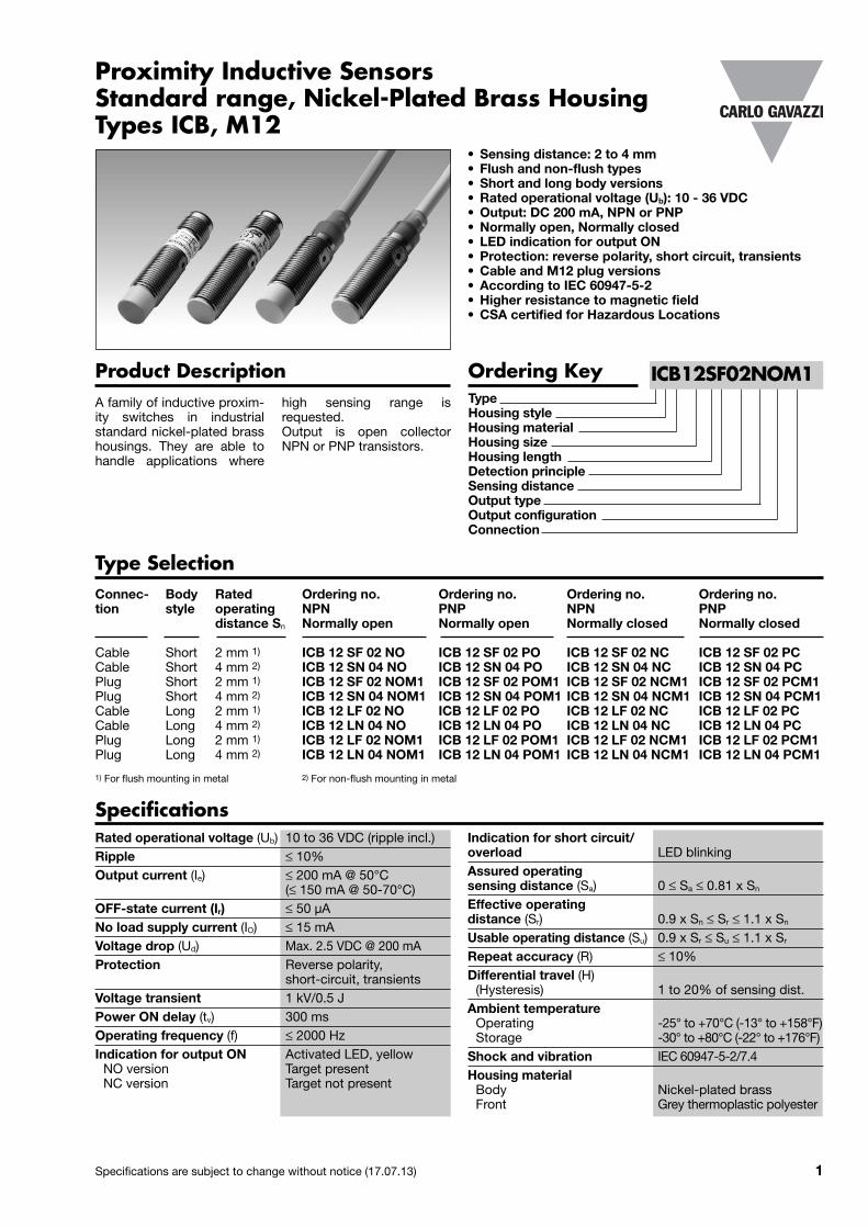
Proximity Inductive Sensors
Specifications are subject to change without notice (17.07.13) 1
Connec- Body Rated Ordering no. Ordering no. Ordering no. Ordering no.tion style operating NPN PNP NPN PNP distance Sn Normally open Normally open Normally closed Normally closed
Cable Short 2 mm 1) ICB 12 SF 02 NO ICB 12 SF 02 PO ICB 12 SF 02 NC ICB 12 SF 02 PCCable Short 4 mm 2) ICB 12 SN 04 NO ICB 12 SN 04 PO ICB 12 SN 04 NC ICB 12 SN 04 PCPlug Short 2 mm 1) ICB 12 SF 02 NOM1 ICB 12 SF 02 POM1 ICB 12 SF 02 NCM1 ICB 12 SF 02 PCM1Plug Short 4 mm 2) ICB 12 SN 04 NOM1 ICB 12 SN 04 POM1 ICB 12 SN 04 NCM1 ICB 12 SN 04 PCM1Cable Long 2 mm 1) ICB 12 LF 02 NO ICB 12 LF 02 PO ICB 12 LF 02 NC ICB 12 LF 02 PCCable Long 4 mm 2) ICB 12 LN 04 NO ICB 12 LN 04 PO ICB 12 LN 04 NC ICB 12 LN 04 PCPlug Long 2 mm 1) ICB 12 LF 02 NOM1 ICB 12 LF 02 POM1 ICB 12 LF 02 NCM1 ICB 12 LF 02 PCM1Plug Long 4 mm 2) ICB 12 LN 04 NOM1 ICB 12 LN 04 POM1 ICB 12 LN 04 NCM1 ICB 12 LN 04 PCM1
1) For flush mounting in metal 2) For non-flush mounting in metal
Product DescriptionA family of inductive proxim-ity switches in industrialstandard nickel-plated brasshousings. They are able tohandle applica tions where
high sensing range isrequested. Output is open collectorNPN or PNP transistors.
Standard range, Nickel-Plated Brass HousingTypes ICB, M12
Type Selection
• Sensing distance: 2 to 4 mm• Flush and non-flush types• Short and long body versions• Rated operational voltage (Ub): 10 - 36 VDC• Output: DC 200 mA, NPN or PNP• Normally open, Normally closed• LED indication for output ON• Protection: reverse polarity, short circuit, transients• Cable and M12 plug versions• According to IEC 60947-5-2• Higher resistance to magnetic field• CSA certified for Hazardous Locations
Ordering KeyTypeHousing styleHousing materialHousing sizeHousing lengthDetection principleSensing distanceOutput typeOutput configurationConnection
Specifications Indication for short circuit/ overload LED blinkingAssured operating sensing distance (Sa) 0 ≤ Sa ≤ 0.81 x SnEffective operating distance (Sr) 0.9 x Sn ≤ Sr ≤ 1.1 x SnUsable operating distance (Su) 0.9 x Sr ≤ Su ≤ 1.1 x SrRepeat accuracy (R) ≤ 10%Differential travel (H) (Hysteresis) 1 to 20% of sensing dist.Ambient temperature Operating -25° to +70°C (-13° to +158°F) Storage -30° to +80°C (-22° to +176°F)Shock and vibration IEC 60947-5-2/7.4Housing material Body Nickel-plated brass Front Grey thermoplastic polyester
Rated operational voltage (Ub) 10 to 36 VDC (ripple incl.)Ripple ≤ 10%Output current (Ie) ≤ 200 mA @ 50°C (≤ 150 mA @ 50-70°C)OFF-state current (Ir) ≤ 50 µANo load supply current (IO) ≤ 15 mA Voltage drop (Ud) Max. 2.5 VDC @ 200 mAProtection Reverse polarity, short-circuit, transientsVoltage transient 1 kV/0.5 JPower ON delay (tv) 300 msOperating frequency (f) ≤ 2000 HzIndication for output ON Activated LED, yellow NO version Target present NC version Target not present
ICB12SF02NOM1
2 Specifications are subject to change without notice (17.07.13)
ICB, M12
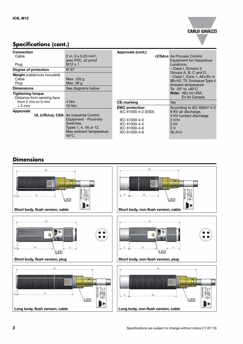
Dimensions
Specifications (cont.)Approvals (cont.) CCSAUS As Process Control Equipment for Hazardous Locations. - Class I, Division 2, Groups A, B, C and D. - Class I, Zone 1, AEx/Ex d IIB+H2, T5, Enclosure Type 4. Ambient temperature Ta: -25° to +60°C. Note: AEx for USA, Ex for CanadaCE-marking YesEMC protection According to IEC 60947-5-2 IEC 61000-4-2 (ESD) 8 KV air discharge, 4 KV contact discharge IEC 61000-4-3 3 V/m IEC 61000-4-4 2 kV IEC 61000-4-6 3 V IEC 61000-4-8 30 A/m
Connection Cable 2 m, 3 x 0.25 mm2, grey PVC, oil proof Plug M12 x 1Degree of protection IP 67 Weight (cable/nuts included) Cable Max. 120 g Plug Max. 30 gDimensions See diagrams belowTightening torque Distance from sensing face from 2 mm to 5 mm 4 Nm > 5 mm 10 NmApprovals UL (CRUUS), CSA: As Industrial Control Equipment - Proximity Switches. Types 1, 4, 4X or 12. Max ambient temperature 40°C.
1 32
50
25
50
8
Short body, non-flush version, cable
1 30
51
11
Short body, flush version, plug
8 23
51
11
Short body, non-flush version, plug
1 47
65
Long body, flush version, cable
8 40
65
Long body, non-flush version, cable
Short body, flush version, cable
1
4
2
3
1
4
2
3
LED
LED LED
LED LED
LED
Specifications are subject to change without notice (17.07.13) 3
ICB, M12
1 45
66
11
Long body, flush version, plug
8 38
66
11
Long body, non-flush version, plug
Flush sensors, when installed together in damping material,must be according to Picture 2A.
Non-flush sensors, when installed together in dampingmaterial, must be according to Picture 2B.
d dd 4 x ddd
d : sensor diameter
InstallationFlush sensor, when installed in damping material, must beaccording to Picture 1A.
Non-flush sensor, when installed in damping material, mustbe according to Picture 1B.
≥ 3 x Sn
≥ 4 x dd
≥ 3 x Sn
≥ 2 x Sn
Free zone or non-damping material
Free zone or non-damping material
Sn : nominal sensing distanced : sensor diameter
Picture 1A Picture 1B
Sn : nominal sensing distanced : sensor diameter
Picture 2A Picture 2B
d : sensor diameter
6 x Sn
For sensors installed opposite each other, a minimum spaceof 6 x Sn (the nominal sensing distance) must be observed(See Picture 3).
Picture 3
Sn : nominal sensing distance
1
4
2
3
1
4
2
3
LEDLED
Dimensions (cont.)
4 Specifications are subject to change without notice (17.07.13)
ICB, M12
Delivery Contents• Inductive proximity switch ICB.• 2 nuts NPB• Packaging: plastic bag
Picture 4
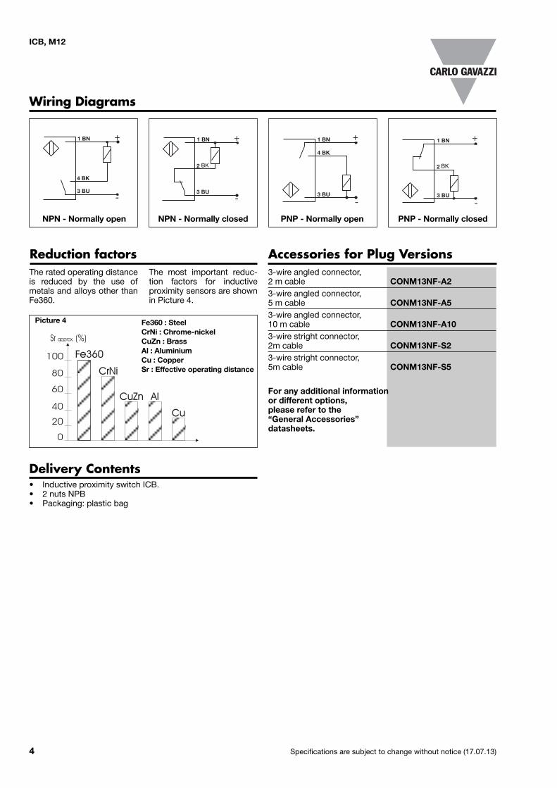
Reduction factorsThe rated operating distanceis reduced by the use ofmetals and alloys other thanFe360.
The most important reduc-tion factors for inductiveproximity sensors are shownin Picture 4.
Fe360 : SteelCrNi : Chrome-nickelCuZn : BrassAl : AluminiumCu : CopperSr : Effective operating distance
Accessories for Plug Versions 3-wire angled connector,2 m cable CONM13NF-A23-wire angled connector, 5 m cable CONM13NF-A53-wire angled connector, 10 m cable CONM13NF-A103-wire stright connector, 2m cable CONM13NF-S23-wire stright connector, 5m cable CONM13NF-S5
For any additional information or different options, please refer to the “General Accessories” datasheets.
Wiring Diagrams
+
-
1 BN
4 BK
3 BU
+
-
1 BN
2 WH
3 BU
+
-
1 BN
4 BK
3 BU
+
-
1 BN
2 WH
3 BU
NPN - Normally open NPN - Normally closed PNP - Normally open PNP - Normally closed
BK BK
Recommended