PhD DefenseRelative-Motion Trajectory Generation and Maintenance for
Multi-Spacecraft Swarms
Rahul Rughani
OVERVIEW | 2
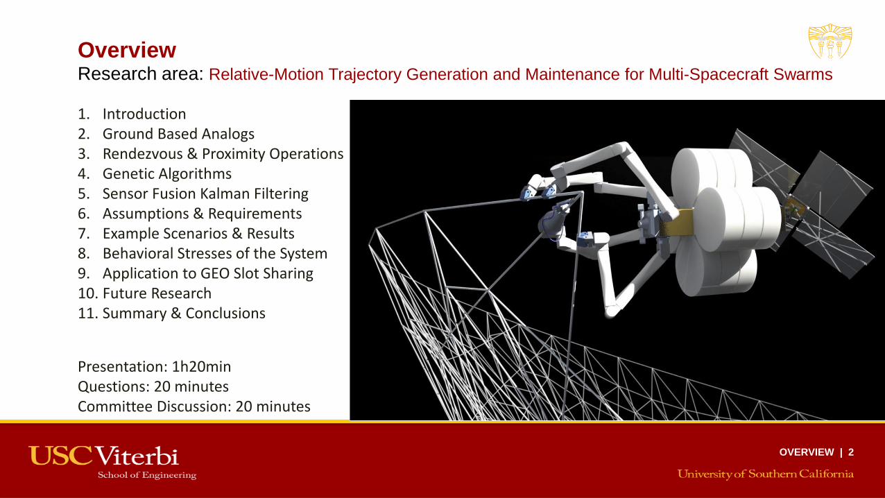
Overview
1. Introduction2. Ground Based Analogs3. Rendezvous & Proximity Operations4. Genetic Algorithms5. Sensor Fusion Kalman Filtering6. Assumptions & Requirements7. Example Scenarios & Results8. Behavioral Stresses of the System9. Application to GEO Slot Sharing10. Future Research11. Summary & Conclusions
Research area: Relative-Motion Trajectory Generation and Maintenance for Multi-Spacecraft Swarms
Presentation: 1h20minQuestions: 20 minutesCommittee Discussion: 20 minutes
1. Barnhart, D., Rughani, R., Allam, Barnhart, D., Rughani, R., Allam, J., Weeden, B., Slane, F., and Christensen, I., “Using Historical Practices to Develop Safety Standards for Cooperative On-Orbit Rendezvous and Proximity Operations”, 69th International Astronautical Congress (IAC) Bremen Germany 1-5 October 2018, IAC-18,D1,5,8,x45161
2. Barnhart, D., Rughani, R., Allam, J., “Design-Based Safe Operable Metrics for Earth Regime RPO”, 10th Annual IAASS Space Safety Conference, May 15-17, 2019 (El Segundo, CA)
3. Barnhart, D.A., Rughani, R., “On-Orbit Servicing Ontology applied to Recommended Standards for Satellites in Earth Orbit”, 70th Annual International Astronautical Congress, 21-25 October 2019 (Washington, D.C.)
4. Rughani, R., Villafana, L., & Barnhart, D. A., “Swarm RPO and Docking Simulation on a 3DOF Air Bearing Platform”, 70th International Astronautical Congress (IAC). Washington D.C., United States, 21-25 October 2019.
5. Rughani R., Barnhart, D.A. “Using Genetic Algorithms for Safe Swarm Trajectory Optimization.” 30th AIAA/AAS Space Flight Mechanics Meeting. Orlando Fl, 6-10 January 2020
6. Rughani, R., Barnhart, D.A., “Safe Construction in Space: Using Swarms of Small Satellites for In-Space Manufacturing”, 34th Annual Small Satellite Conference. Logan UT, August 1-6, 2020 (Virtual)
Conference Publications
PUBLICATIONS | 3

1. Barnhart, D.A., and Rughani, R., “On-orbit servicing ontology applied to recommended standards for satellites in earth orbit”, Journal of Space Safety Engineering, https://doi.org/10.1016/j.jsse.2020.02.002
2. Barnhart, D.A., Rughani, R., Allam, J.J., Clarke, K.W., “Initial Safety Posture Investigations for Earth Regime Rendezvous and Proximity Operations”, Journal of Space Safety Engineering, https://doi.org/10.1016/j.jsse.2020.06.010
Peer Reviewed Journal Publications
Published
Submitted – Pending Review
1. Rughani, R., Barnhart, D.A., “Using Genetic Algorithms for Safe Spacecraft Swarm Trajectory Generation”, Acta Astronautica (in review).
2. Rughani, R., Presser, T., Barnhart, D.A., “The Use of Genetic Algorithms for Novel Geostationary Satellite Co-location Trajectories”, Journal of Guidance, Control, and Dynamics (in review)
PUBLICATIONS | 4

Advances Made to State of the Art
PUBLICATIONS | 5
• Created a novel method for swarm trajectory generation using Genetic Algorithms
• Created an algorithmically controlled method for optimized aggregation, in close proximity to a growing structure
• Implemented a Sensor Fusion Kalman Filter for swarm trajectory maintenance
• Created a novel method for slot-sharing stationkeeping of GEO spacecraft that reduces Delta-V vs existing methods (provisional patent)

Introduction

Research Goal
Advance the state of the art for spacecraft swarm operations to enable large-scale in-space manufacturing in the not-too-distant future
Credit: Northrop Grumman
Credit: Northrop Grumman
MEV-1 docks with Intelsat-901
Credit: Jack Olson / Getty Images
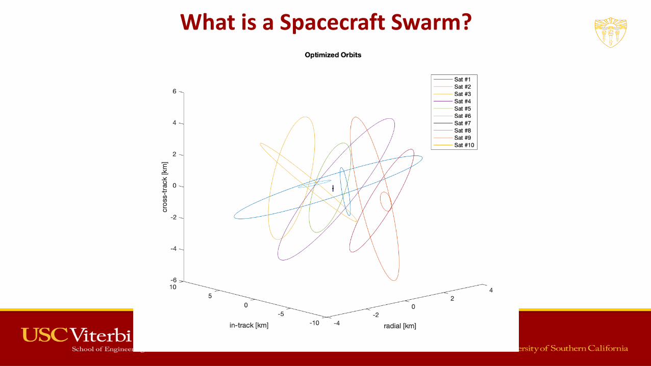
What is a Spacecraft Swarm?
Depiction of Covariance Ellipses on Swarm

Current State of the Art
• MEV-1 successfully docked to a retired GEO spacecraft to provide mission extension services Credit: Northrop Grumman
Credit: Northrop Grumman
MEV-1 docks with Intelsat-901

Swarm RPO Operations – State of the Art
- Specific energy-based optimization [1]
- Primarily static formation flying configs
- Eccentricity/Inclination vector alignment (E/I) [2]
- Good for smaller swarm sizes. E/I method doesn’t scale well
- Relative Pose Estimation [3]
- Solves the problem of distributed attitude determination and control
- Sliding-Mode Control Algorithms [4]
- Good for large swarms, but primarily reactionary rather than predictive, thus uses large amounts of dV
- Convex Programming [5,6]
- Best for irregular gravity fields around asteroids[1] Morgan et. al. Swarm-keeping strategies for spacecraft under J2 and atmospheric drag perturbations. Journal of Guidance, Control, and Dynamics, 35(5):1492–1506, 2012.[2] Simone D’Amico. Autonomous formation flying in low earth orbit. 2010.[3] William Bezouska and David Barnhart. Decentralized cooperative localization with relative pose estimation for a spacecraft swarm. In 2019 IEEE Aerospace Conference, pages 1–13. IEEE, 2019[4] Chakravarthini M Saaj, Vaios Lappas, and Veysel Gazi. Spacecraft swarm navigation and control using artificial potential field and sliding mode control. In 2006 IEEE International Conference on Industrial Technology, pages 2646–2651. IEEE, 2006[5] Bandyopadhyay et. al. Distributed fast motion planning for spacecraft swarms in cluttered environments using spherical expansions and sequence of convex optimization problems. 2017.[6] Bandyopadhyay et. al. Distributed spatiotemporal motion planning for spacecraft swarms in cluttered environments. In AIAA SPACE and Astronautics Forum and Exposition, page 5323, 2017.

Five Classes of Swarms [7]
Class 0: no coordination either in movement, sensing, or communication
Class 1: Each spacecraft coordinates its movement, but there is no explicit communication coordination or sensing coordination.
Class 2: movement and communication coordination. Swarm has collective sensing capabilities, but is not optimized
Class 3: Each spacecraft coordinates sensing with communication and position, but is still not collectively optimized
Class 4: positioning, movement, communication, and sensing are coordinated to perform system level optimization. Computing is evenly distributed within the swarm
[7] Ravi Nallapu and Jekan Thangavelautham. Spacecraft swarm attitude control for small body surface observation. arXiv preprint arXiv:1902.02084, 2019
Five Classes of Swarms
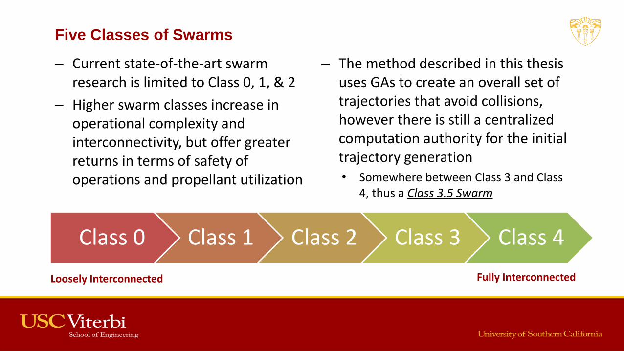
– Current state-of-the-art swarm research is limited to Class 0, 1, & 2
– Higher swarm classes increase in operational complexity and interconnectivity, but offer greater returns in terms of safety of operations and propellant utilization
– The method described in this thesis uses GAs to create an overall set of trajectories that avoid collisions, however there is still a centralized computation authority for the initial trajectory generation• Somewhere between Class 3 and Class
4, thus a Class 3.5 Swarm
Class 0 Class 1 Class 2 Class 3 Class 4
Loosely Interconnected Fully Interconnected
DARPA F6
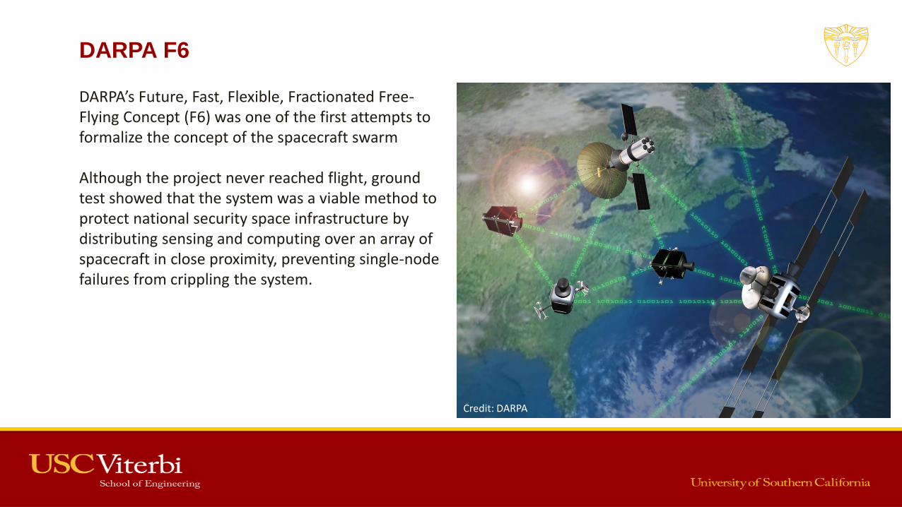
DARPA’s Future, Fast, Flexible, Fractionated Free-Flying Concept (F6) was one of the first attempts to formalize the concept of the spacecraft swarm
Although the project never reached flight, ground test showed that the system was a viable method to protect national security space infrastructure by distributing sensing and computing over an array of spacecraft in close proximity, preventing single-node failures from crippling the system.
Credit: DARPA

DARPA Phoenix – Satlets
DARPA’s Phoenix satellite servicing project included Satlets, small free-flying spacecraft capable of aggregated together to form larger objects
These were essentially building blocks for spacecraft that can be assembled and reconfigured to match the mission requirements and can change with the needs of the mission.
Credit: Novawurks Credit: Novawurks

Motivation & Use Cases
On-orbit assembly Cooperative Proximity Operations

Increasing Density of Spacecraft in LEO
Credit: Analytical Graphics
• Thousands of satellites are planned for LEO over the coming decade
• Crowding of LEO will require new and novel methods for collision detection and avoidance in close proximity

Increasing Density of Spacecraft in LEO
Credit: Kyle Clarke
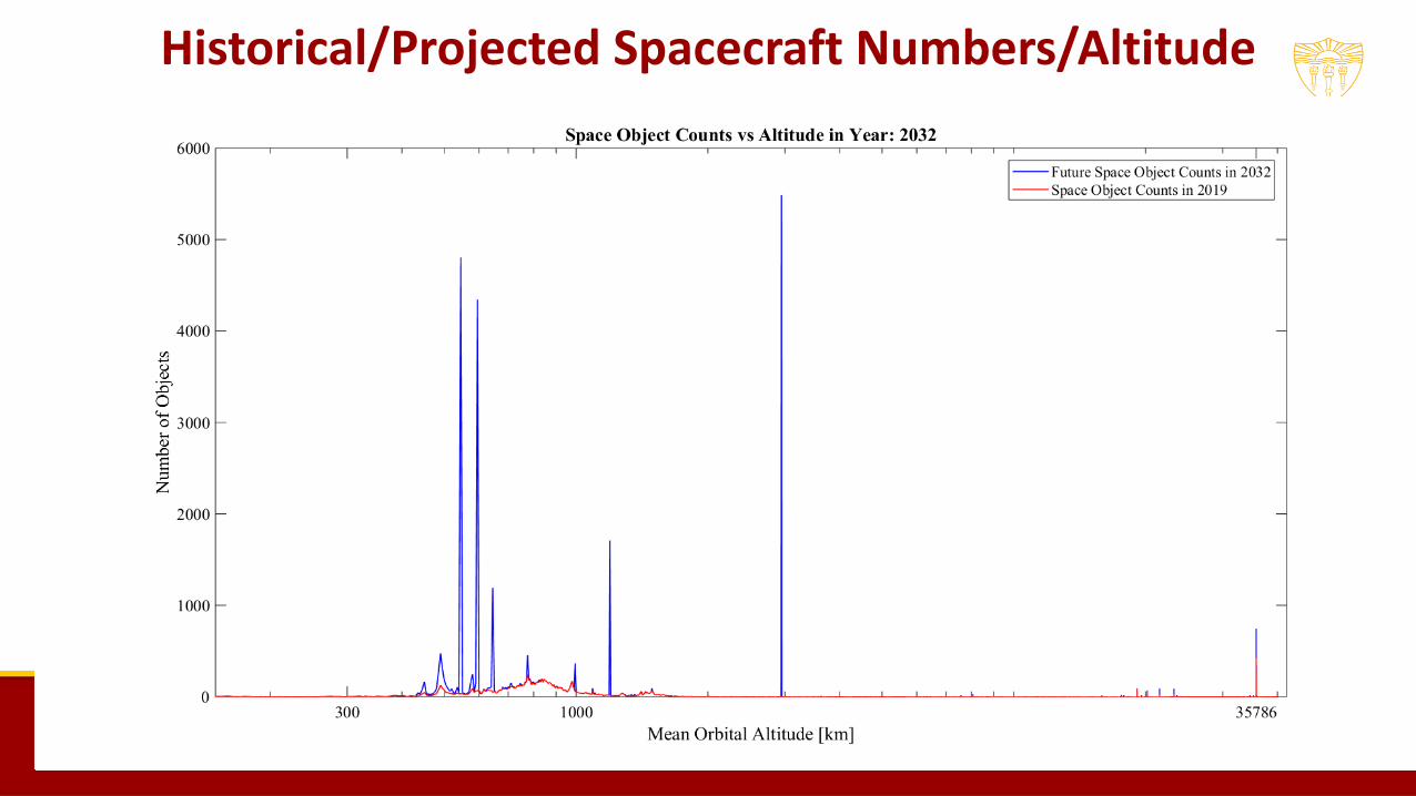
Historical/Projected Spacecraft Numbers/Altitude

PROBLEM STATEMENT | 20
Problem Statement & Solution Approach
1. Given a co-located swarm of N free-flying spacecraft capable of relative position, velocity, and orientation determination, generate a set of trajectories that enable these spacecraft to complete their individual tasks within their ∆V budgets, while mitigating collision risks over a minimum 24hr period• Can be solved using Genetic Algorithms, an evolutionary optimization scheme
2. Given an existing set of co-located swarm trajectories as generated by the solution to the first problem, maintain these trajectories in real-time, accounting for deviations due to injection errors, unaccounted for higher-order or non-gravitational perturbations, sensor errors, or system noise• Can be solved using a Sensor Fusion Kalman Filter, combining shared sensor data from all
spacecraft in the swarm3. Given an existing set of co-located swarm trajectories as generated by the solution to the first
problem, generate a new set of trajectories for a modified swarm, with some spacecraft either added or removed, while minimizing the ∆V required to re-position the existing swarm spacecraft to accommodate the new spacecraft• Can be solved using Genetic Algorithms, similar to problem 1
Research Path
Credit: Analytical Graphics
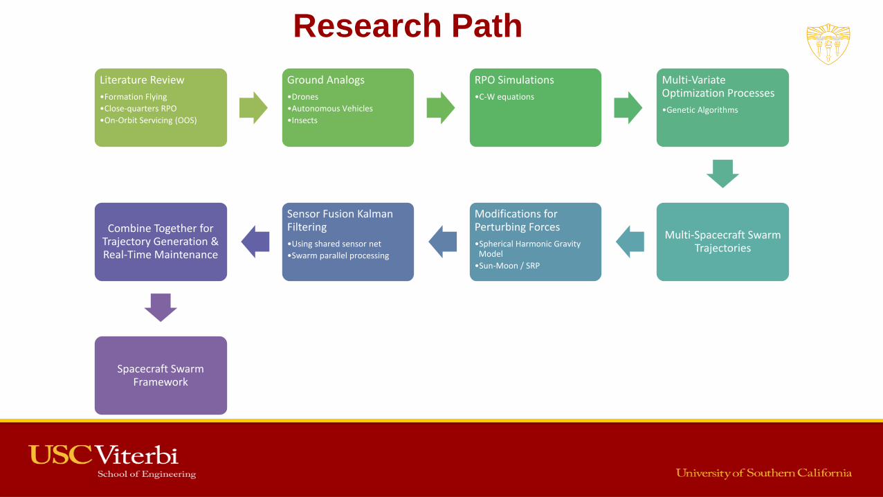
Literature Review
•Formation Flying
•Close-quarters RPO
•On-Orbit Servicing (OOS)
Ground Analogs
•Drones
•Autonomous Vehicles
•Insects
RPO Simulations
•C-W equations
Multi-Variate Optimization Processes
•Genetic Algorithms
Multi-Spacecraft Swarm Trajectories
Modifications for Perturbing Forces
•Spherical Harmonic Gravity Model
•Sun-Moon / SRP
Sensor Fusion Kalman Filtering
•Using shared sensor net
•Swarm parallel processing
Combine Together for Trajectory Generation & Real-Time Maintenance
Spacecraft Swarm Framework

Ground Based
Analogs
SWARM EXAMPLES | 23
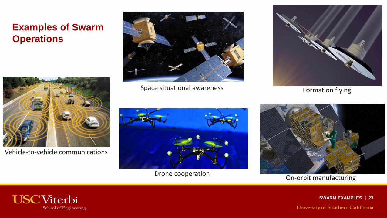
Examples of Swarm
Operations
Vehicle-to-vehicle communications
Drone cooperation
Space situational awareness
On-orbit manufacturing
Formation flying
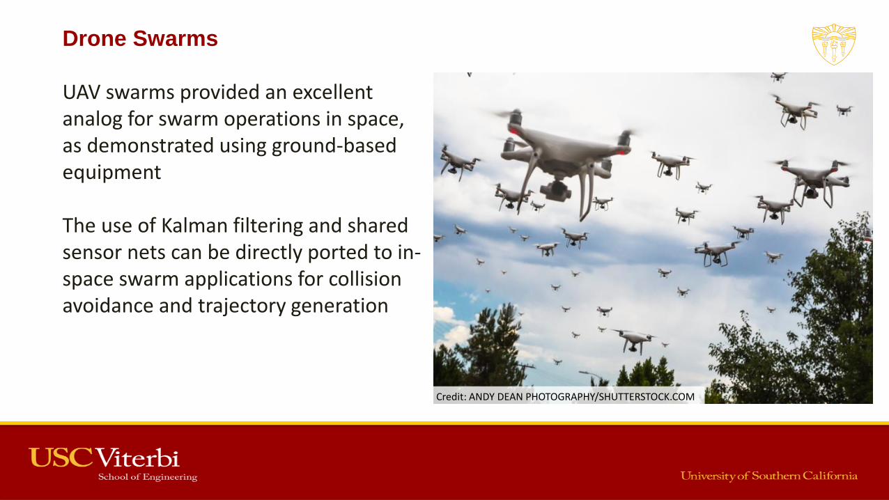
Drone Swarms
UAV swarms provided an excellent analog for swarm operations in space, as demonstrated using ground-based equipment
The use of Kalman filtering and shared sensor nets can be directly ported to in-space swarm applications for collision avoidance and trajectory generation
Credit: ANDY DEAN PHOTOGRAPHY/SHUTTERSTOCK.COM

Insect Analogs
• Bees were also considered as swarm analogs
• Bees display task coordination and division of labor, concepts ported into spacecraft swarm ops
– Constant communication used to prevent collisions and transmit directions
Depiction of Covariance Ellipses on Swarm

Rendezvous and
Proximity Operations

Local-Vertical Local-Horizontal (LVLH) Coordinate Frame
Definition:
X.ax = radial (green)- outward radial vector from
center of Earth to targetY.ax = in-track (cyan)- parallel to velocity vector for
circular reference orbit. Otherwise forms triad with X&Z
Z.ax = cross-track (purple)- normal to orbital plane
(aligned with angular momentum vector)

they are ”orbiting” around acommon point in space. Theme-
chanics of the free-trajectory motion following these relative
motion orbital tracksare well known and understood, having
been used for more than fifty years, prior to theApollo mis-
sions [5]. However, methods to autonomously maintain and
guide such relativemotion trajectories are not aswell under-
stood, given that robust automated rendezvous techniques
havebeen available for just over adecade [19]. Fig. 2 shows
a depiction of what a set of swarm orbits may look like in
the relativemotion frame.
Fig. 2: Swarm of spaceraft in relativemotion
3.1 Mathematical Formulation
Relative orbital motion takes place in the Local-Vertical
Local-Horizontal (LVLH) rotating reference frame. This
non-inertial reference frame iscentered on apoint in space,
in orbit around theEarth, which could beaClient spacecraft,
a waypoint, or some other point of interest. The x-axis is
directed along theoutward radial vector from the center of
the Earth to the target, the z-axis is normal to the orbital
plane of the target, and the y-axis lies within the orbital
plane, constrained by the x- and z-axes to form a triad.
This motion can be described by the following equations of
motion, where R is the vector from thecenter of the Earth to
theClient, and dr is thevector from theClient to theServicer
vehicle:
d r = − R− µR+ dr
kR+ drk3(1)
This equation of motion isanonlinear system of equations;
however, alinearized approach isdesired to usein areal-time
guidance application. If the target spacecraft is restricted to
be in acircular orbit, thesystem can bedefined in aclosed-
form linearized approximation by the Clohessy-Wiltshire
(C-W) equations [18], laid out below
dx− 3n2dx− 2ndy = 0 (2)
dy+ 2ndx = 0 (3)
dz+ n2dz= 0 (4)
These differential equations are valid while the following
criterion from the linearization process holds:
dr/ R< < 1 (5)
A closed form solution of these coupled partial differential
equations can beobtained, expressed in matrix form below,
enabling the computation of position and velocity at any
point in time:
d~r(t) = [F rr (t)]d~r0 + [F rv(t)]d~v0 (6)
d~v(t) = [F vr (t)]d~r0 + [F vv(t)]d~v0 (7)
where the initial position and velocity are
d~r0 =
2
4dx0
dy0
dz0
3
5 , d~v0 =
2
4du0
dv0
dw0
3
5
n : angular rotation rate of orbit (rad/s)
t : time since initial conditions
F rr (t) =
2
44− 3cosnt 0 0
6(sinnt − nt) 1 0
0 0 cosnt
3
5 (8)
F rv(t) =
2
4
1n sinnt 2
n(1− cosnt) 02n(cosnt − 1) 1
n(4sinnt − 3nt) 0
0 0 1n
sinnt
3
5 (9)
3
they are ”orbiting” around acommon point in space. Theme-
chanics of the free-trajectory motion following these relative
motion orbital tracks are well known and understood, having
been used for more than fifty years, prior to the Apollo mis-
sions [5]. However, methods to autonomously maintain and
guide such relative motion trajectories are not as well under-
stood, given that robust automated rendezvous techniques
have been available for just over a decade [19]. Fig. 2 shows
a depiction of what a set of swarm orbits may look like in
the relativemotion frame.
Fig. 2: Swarm of spaceraft in relativemotion
3.1 Mathematical Formulation
Relative orbital motion takes place in the Local-Vertical
Local-Horizontal (LVLH) rotating reference frame. This
non-inertial reference frame iscentered on apoint in space,
in orbit around the Earth, which could be a Client spacecraft,
a waypoint, or some other point of interest. The x-axis is
directed along the outward radial vector from the center of
the Earth to the target, the z-axis is normal to the orbital
plane of the target, and the y-axis lies within the orbital
plane, constrained by the x- and z-axes to form a triad.
This motion can be described by the following equations of
motion, where R is the vector from the center of the Earth to
theClient, and dr is thevector from theClient to theServicer
vehicle:
d r = − R− µR+ dr
kR+ drk3(1)
This equation of motion isanonlinear system of equations;
however, a linearized approach isdesired to usein areal-time
guidance application. If the target spacecraft is restricted to
be in acircular orbit, thesystem can bedefined in aclosed-
form linearized approximation by the Clohessy-Wiltshire
(C-W) equations [18], laid out below
dx− 3n2dx− 2ndy = 0 (2)
dy+ 2ndx = 0 (3)
dz+ n2dz= 0 (4)
These differential equations are valid while the following
criterion from the linearization process holds:
dr/ R< < 1 (5)
A closed form solution of these coupled partial differential
equations can beobtained, expressed in matrix form below,
enabling the computation of position and velocity at any
point in time:
d~r(t) = [F rr (t)]d~r0 + [F rv(t)]d~v0 (6)
d~v(t) = [F vr (t)]d~r0 + [F vv(t)]d~v0 (7)
where the initial position and velocity are
d~r0 =
2
4dx0
dy0
dz0
3
5 , d~v0 =
2
4du0
dv0
dw0
3
5
n : angular rotation rate of orbit (rad/s)
t : time since initial conditions
F rr (t) =
2
44− 3cosnt 0 0
6(sinnt − nt) 1 0
0 0 cosnt
3
5 (8)
F rv(t) =
2
4
1n
sinnt 2n(1− cosnt) 0
2n(cosnt − 1) 1
n(4sinnt − 3nt) 0
0 0 1n
sinnt
3
5 (9)
3
Rendezvous and Proximity Operations (RPO)

Swarm of Spacecraft in Relative Motion
LVLH TrajectoriesInertial Trajectories

Gravitational Perturbations
Irregularities of Earth’s gravitational field (GRACE data)
Although the C-W equations are a good approximation of relative motion trajectories, they fail to account for perturbations of the orbit and thus are only a first order solution
GA solver was thus implemented using a two-stage process, with the perturbed gravitational potential. This enables more accurate predictions farther in the future

Gravitational Perturbations
Sun-Moon: perturbations from the Sun’s and Moon’s gravitational fields are significant at GEO
SRP: Solar Radiation Pressure perturbations depend on the area-to-mass ratio of the spacecraft, and are significant in GEO, or for large spacecraft in LEO
Genetic Algorithms

Problem: How to quickly and efficiently determine a set of trajectories for a swarm of spacecraft, in relative motion, that don’t collide
– Also minimize delta-V and perform mission-specific tasks
Solution: Genetic Algorithms
Relative Motion Trajectory Determination

Genetic Algorithms – How Do They Work?
• GAs use principles of Darwinian evolution to progress a set of initial conditions towards a solution
• A fitness function is used to rank solutions to determine which are the fittest that should proceed to the next generation

1. Begin with a set of random or distributed starting points
– Goal is to solve for a closed trajectory over fixed time interval
– Initial conditions are position and velocity
– Larger populations are more diverse but require more computation. Test cases use 200
2. Propagate to find pos/vel at time T
– Want to see if trajectory is closed or not
GA – Generate Population
1
2
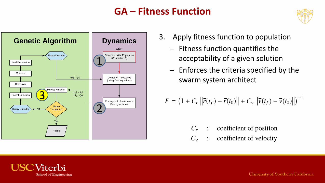
3. Apply fitness function to population
– Fitness function quantifies the acceptability of a given solution
– Enforces the criteria specified by the swarm system architect
GA – Fitness Function
1
23
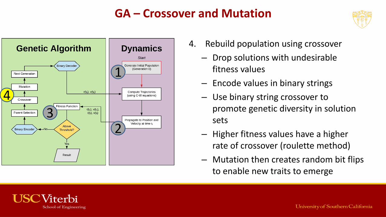
4. Rebuild population using crossover
– Drop solutions with undesirable fitness values
– Encode values in binary strings
– Use binary string crossover to promote genetic diversity in solution sets
– Higher fitness values have a higher rate of crossover (roulette method)
– Mutation then creates random bit flips to enable new traits to emerge
GA – Crossover and Mutation
1
23
4

5. Decode population into their respect variables from binary
6. Propagate trajectories of new initial conditions
7. Continue this process until the desired results are achieved
– Typically a fitness value of 1 (or within a threshold)
– Use a generation counter to limit generations if no solution is found
GA – Achieving the Desired Results
1
23
4
5
6
7

Solving for Spacecraft Swarms
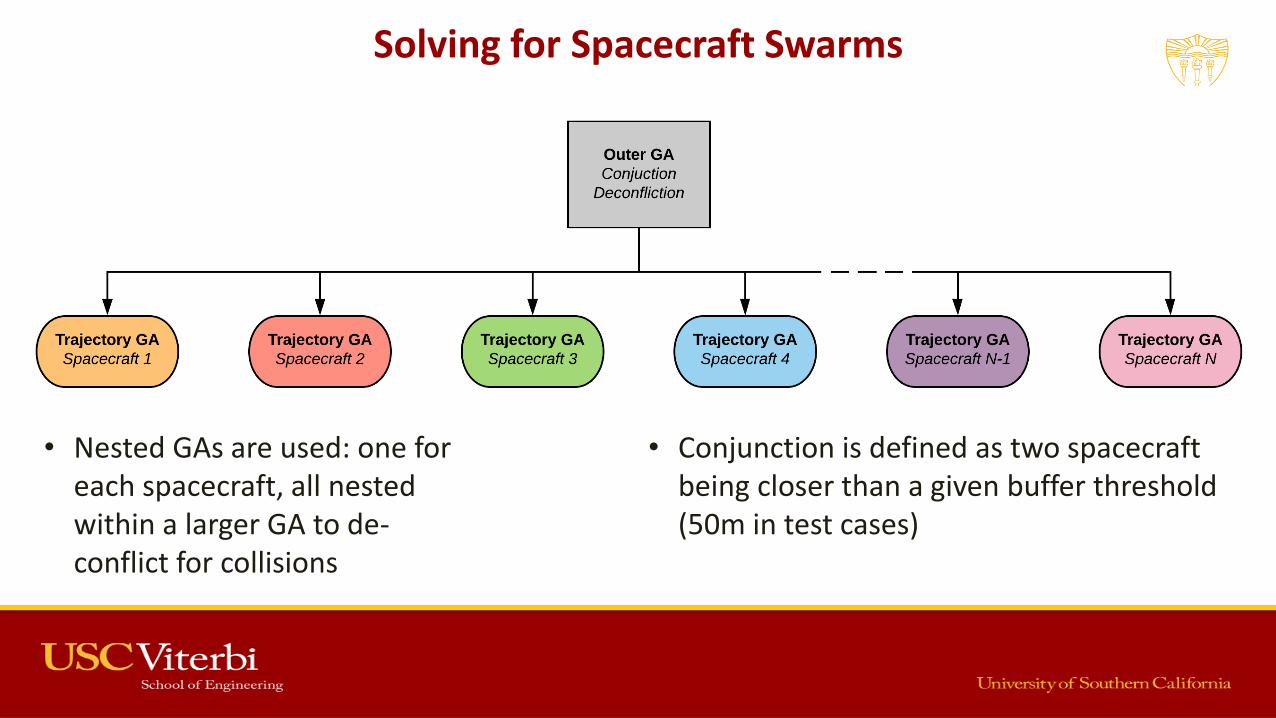
Solving for Spacecraft Swarms
• Nested GAs are used: one for each spacecraft, all nested within a larger GA to de-conflict for collisions
• Conjunction is defined as two spacecraft being closer than a given buffer threshold (50m in test cases)
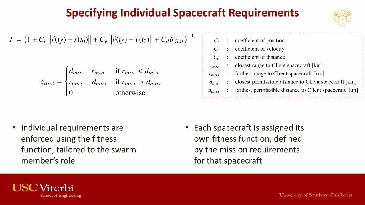
Specifying Individual Spacecraft Requirements
• Individual requirements are enforced using the fitness function, tailored to the swarm member’s role
• Each spacecraft is assigned its own fitness function, defined by the mission requirements for that spacecraft
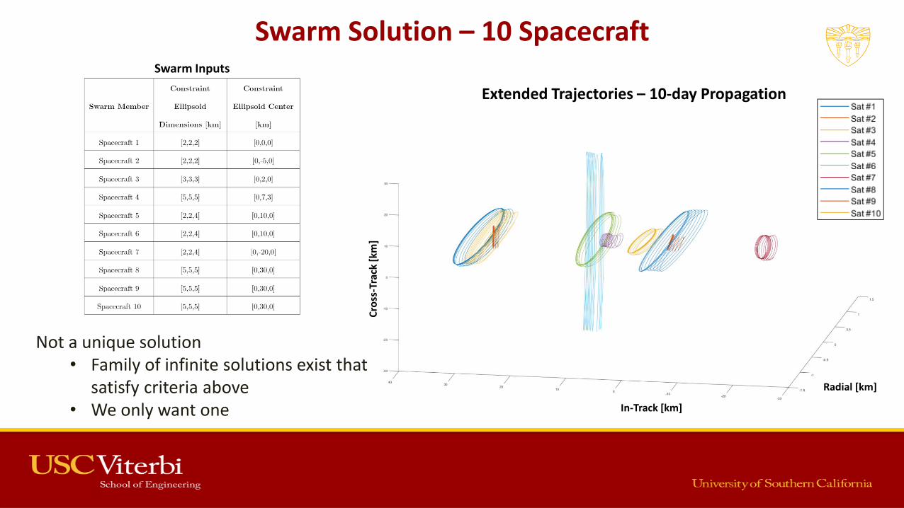
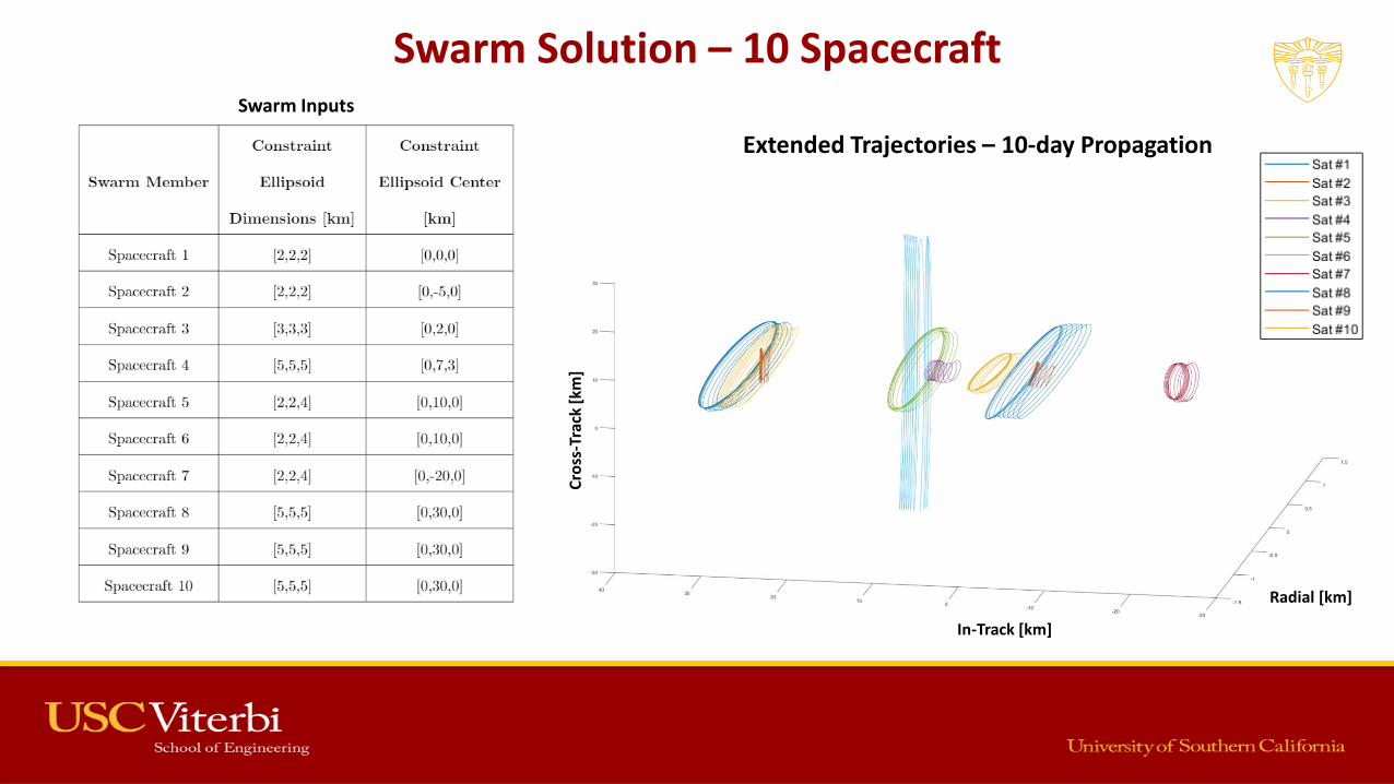
Swarm Solution – 10 Spacecraft
Not a unique solution• Family of infinite solutions exist that
satisfy criteria above• We only want one
Extended Trajectories – 10-day Propagation
In-Track [km]
Radial [km]
Cro
ss-T
rack
[km
]
Swarm Inputs
Dynamic Trajectory Modification
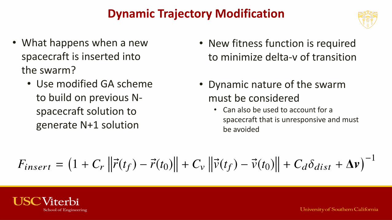
• What happens when a new spacecraft is inserted into the swarm?• Use modified GA scheme
to build on previous N-spacecraft solution to generate N+1 solution
• New fitness function is required to minimize delta-v of transition
• Dynamic nature of the swarm must be considered• Can also be used to account for a
spacecraft that is unresponsive and must be avoided

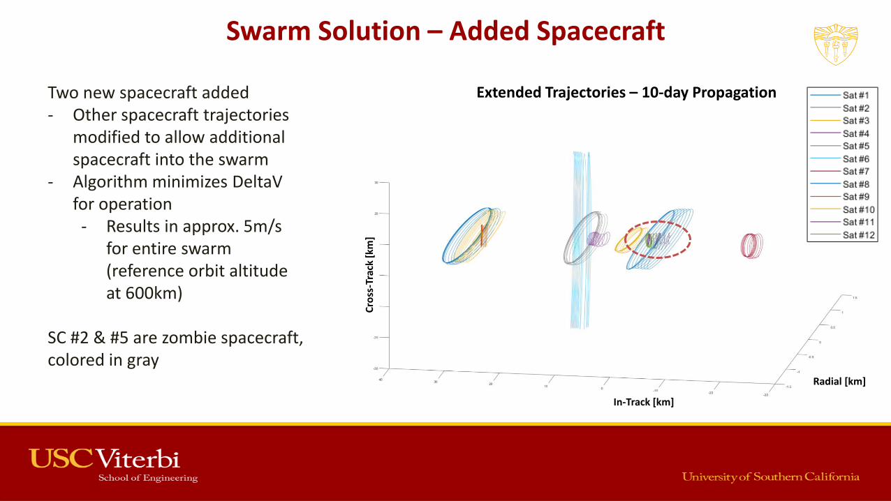
Swarm Solution – Added Spacecraft
Two new spacecraft added - Other spacecraft trajectories
modified to allow additional spacecraft into the swarm
- Algorithm minimizes DeltaVfor operation- Results in approx. 5m/s
for entire swarm (reference orbit altitude at 600km)
Extended Trajectories – 10-day Propagation
In-Track [km]
Radial [km]C
ross
-Tra
ck [
km]

Problems 1 & 3 Have a Solution
1. Given a co-located swarm of N free-flying spacecraft capable of relative position, velocity, and orientation determination, generate a set of trajectories that enable these spacecraft to complete their individual tasks within their ∆V budgets, while mitigating collision risks over a minimum 24hr period• Can be solved using Genetic Algorithms, an evolutionary optimization scheme
2. Given an existing set of co-located swarm trajectories as generated by the solution to the first problem, maintain these trajectories in real-time, accounting for deviations due to injection errors, unaccounted for higher-order or non-gravitational perturbations, sensor errors, or system noise• Can be solved using a Sensor Fusion Kalman Filter, combining shared sensor data from all
spacecraft in the swarm3. Given an existing set of co-located swarm trajectories as generated by the solution to the first
problem, generate a new set of trajectories for a modified swarm, with some spacecraft either added or removed, while minimizing the ∆V required to re-position the existing swarm spacecraft to accommodate the new spacecraft• Can be solved using Genetic Algorithms, similar to problem 1
Sensor Fusion
Kalman Filtering

• Sensor Fusion combines inputs from multiple sensors, spread across the swarm
• Using a Kalman filter, this shared data can be used to pinpoint the relative positions of each spacecraft more accurately, reducing their covariances
Swarm Sensor Fusion

What is a Kalman Filter?
Credit: Tucker McClure, An Uncommon Lab

What is a Kalman Filter?
Credit: Tucker McClure, An Uncommon Lab
Sensor-Fusion Kalman Filtering
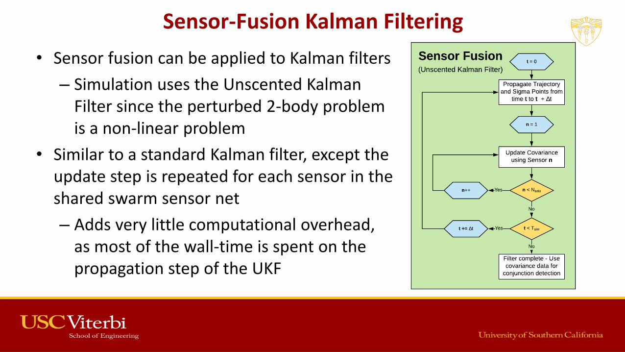
• Sensor fusion can be applied to Kalman filters
– Simulation uses the Unscented Kalman Filter since the perturbed 2-body problem is a non-linear problem
• Similar to a standard Kalman filter, except the update step is repeated for each sensor in the shared swarm sensor net
– Adds very little computational overhead, as most of the wall-time is spent on the propagation step of the UKF
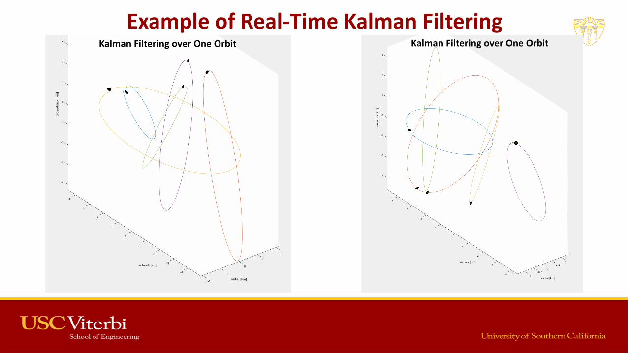
Example of Real-Time Kalman FilteringKalman Filtering over One OrbitKalman Filtering over One Orbit
Trajectory Maintenance
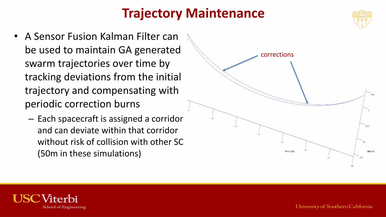
• A Sensor Fusion Kalman Filter can be used to maintain GA generated swarm trajectories over time by tracking deviations from the initial trajectory and compensating with periodic correction burns
– Each spacecraft is assigned a corridor and can deviate within that corridor without risk of collision with other SC (50m in these simulations)
corrections
Patched RPO Transfers
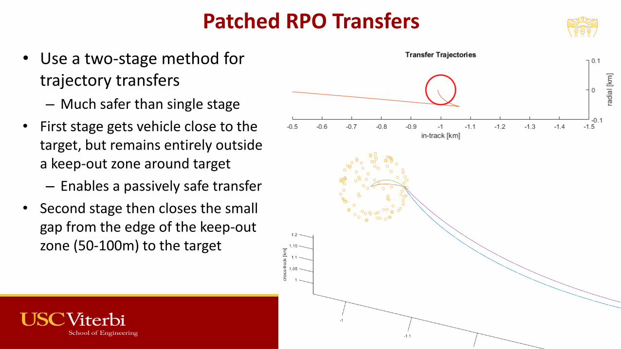
• Use a two-stage method for trajectory transfers
– Much safer than single stage
• First stage gets vehicle close to the target, but remains entirely outside a keep-out zone around target
– Enables a passively safe transfer
• Second stage then closes the small gap from the edge of the keep-out zone (50-100m) to the target

Patched RPO Transfers
• When combined with Kalman filtering, trajectories can be corrected in real-time to account for injection and attitude errors
– Define a safe corridor for transfer
• Kalman filter continuously updates the estimated position of the spacecraft, and re-computes the transfer trajectory in case of deviation
Death of a Spacecraft
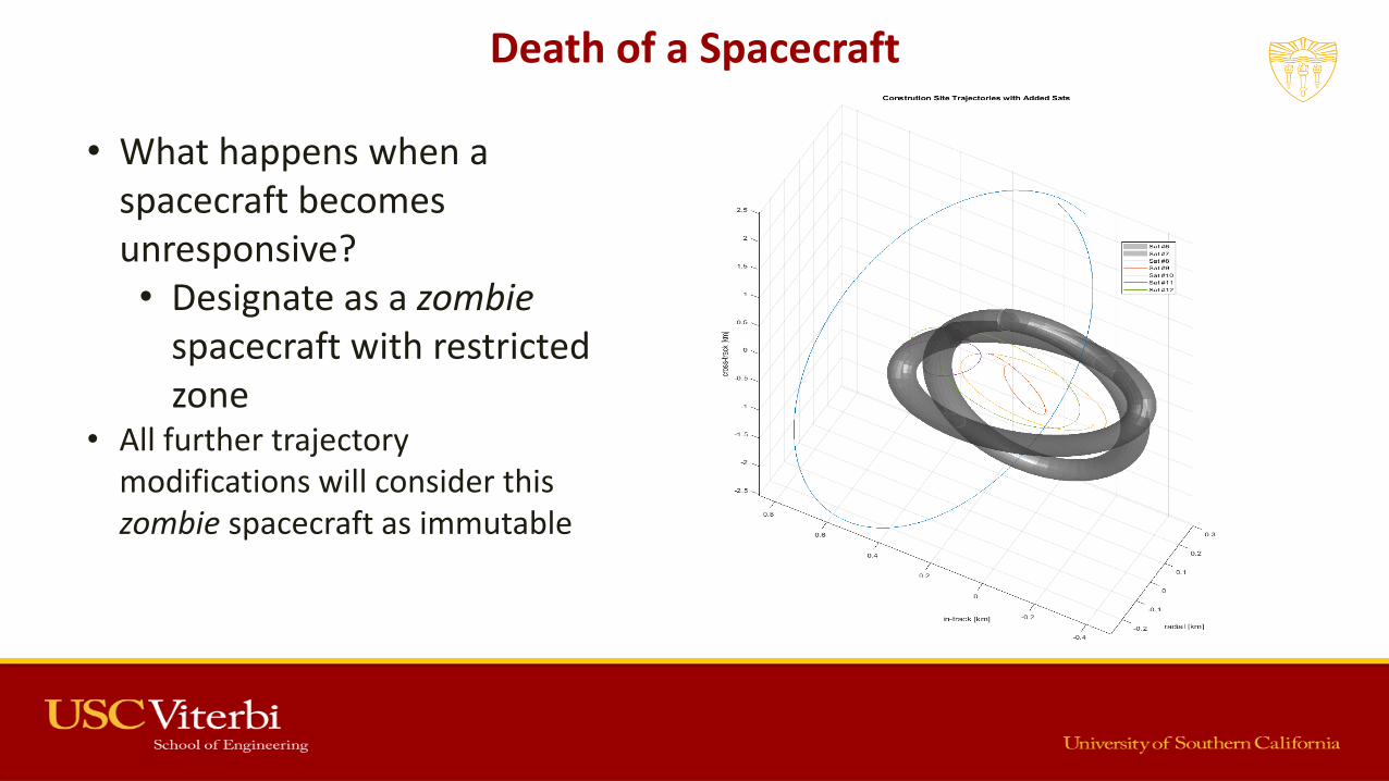
• What happens when a spacecraft becomes unresponsive?• Designate as a zombie
spacecraft with restricted zone
• All further trajectory modifications will consider this zombie spacecraft as immutable

Problem 2 Has a Solution
1. Given a co-located swarm of N free-flying spacecraft capable of relative position, velocity, and orientation determination, generate a set of trajectories that enable these spacecraft to complete their individual tasks within their ∆V budgets, while mitigating collision risks over a minimum 24hr period• Can be solved using Genetic Algorithms, an evolutionary optimization scheme
2. Given an existing set of co-located swarm trajectories as generated by the solution to the first problem, maintain these trajectories in real-time, accounting for deviations due to injection errors, unaccounted for higher-order or non-gravitational perturbations, sensor errors, or system noise• Can be solved using a Sensor Fusion Kalman Filter, combining shared sensor data from all
spacecraft in the swarm3. Given an existing set of co-located swarm trajectories as generated by the solution to the first
problem, generate a new set of trajectories for a modified swarm, with some spacecraft either added or removed, while minimizing the ∆V required to re-position the existing swarm spacecraft to accommodate the new spacecraft• Can be solved using Genetic Algorithms, similar to problem 1

Assumptions &
Requirements

Initial Constraints
1. All spacecraft in the swarm have a known mass, moment of inertia, and center of gravity• Any changes to these values are tracked by the system as fuel is consumed or replenished, and as the
spacecraft are aggregated or dis-aggregated
2. The number of satellites, N, in the swarm is known and finite
3. The relative-motion trajectory’s reference point is moving in a circular orbit• RPO takes place in a non-inertial co-moving reference frame. The origin of this reference frame is assumed to
be traveling in a circular orbit in inertial space
4. Central body’s gravitational field can be modeled using spherical or zonal harmonics
5. Communications delay is negligible
6. All clocks are perfectly synchronized across the swarm
7. Spacecraft that lose communication with the rest of the swarm will enter a passive mode• Ensures predictable trajectories for unresponsive spacecraft
8. Each spacecraft will have a radio beacon signal with unique identifier (IFF)

Spacecraft Requirements
• On-board propulsion (chemical or electric) with minimum 200m/s dV
• 3-axis ADACS with 0.5deg accuracy• Relative position sensors with 5% error
• Conservative estimate for current RADAR and LIDAR capabilities
• Relative speed sensors with 1% error• Conservative estimate for current
RADAR and RF doppler capabilities• Redundant communication systems for
inter-swarm data transfer
Credit: D-Orbit

Examples & Results

Trajectory Example

In-Space Manufacturing
• Trajectory on right shows example of 10-spacecraft swarm for in-space manufacturing
• Swarm roles split up into the staging area, a comm relay, and close-quarters robotic operations
Staging Area
Close-Quarters
Comm Relay
Swarm Solution – 10 Spacecraft
Extended Trajectories – 10-day Propagation
In-Track [km]
Radial [km]
Cro
ss-T
rack
[km
]
Swarm Inputs
Swarm Solution – Added Spacecraft
Two new spacecraft added - Other spacecraft trajectories
modified to allow additional spacecraft into the swarm
- Algorithm minimizes DeltaVfor operation- Results in approx. 5m/s
for entire swarm (reference orbit altitude at 600km)
SC #2 & #5 are zombie spacecraft, colored in gray
Extended Trajectories – 10-day Propagation
In-Track [km]
Radial [km]C
ross
-Tra
ck [
km]
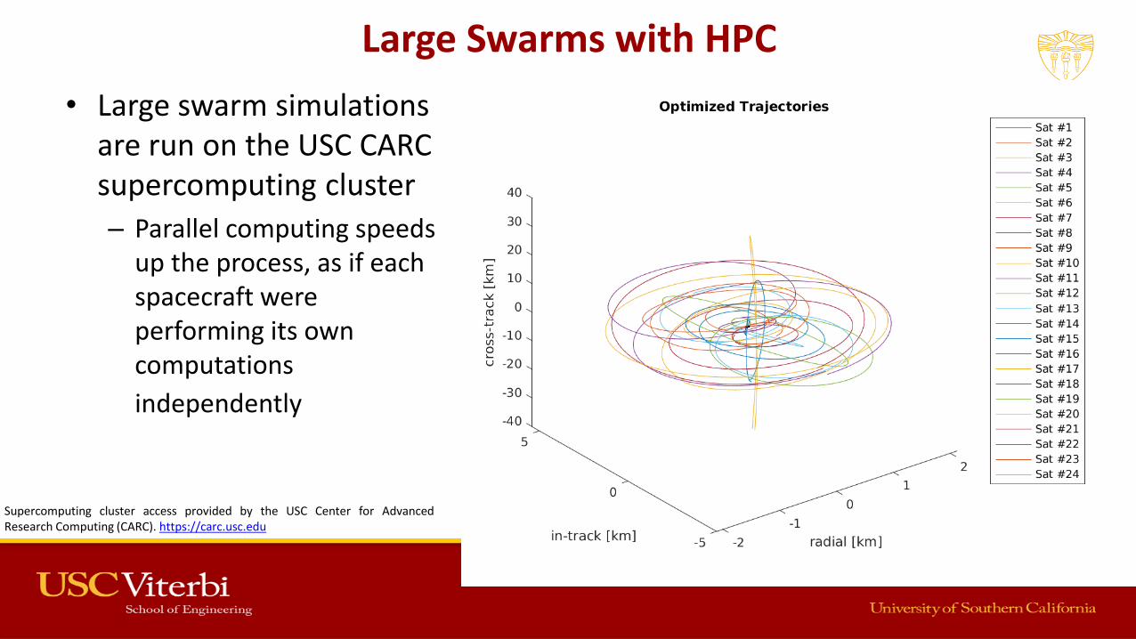
Large Swarms with HPC
• Large swarm simulations are run on the USC CARC supercomputing cluster
– Parallel computing speeds up the process, as if each spacecraft were performing its own computations
independently
Depiction of Covariance Ellipses on SwarmSupercomputing cluster access provided by the USC Center for AdvancedResearch Computing (CARC). https://carc.usc.edu
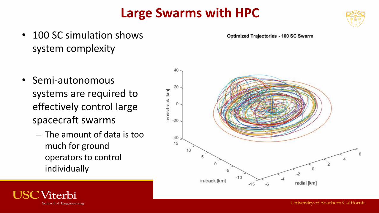
Large Swarms with HPC
• 100 SC simulation shows system complexity
• Semi-autonomous systems are required to effectively control large spacecraft swarms
– The amount of data is too much for ground operators to control individually Depiction of Covariance Ellipses on Swarm

In-Space Assembly Example
• In-space assembly of the Hermes spaceship using a 10-spacecraft swarm
• Ship is composed of five equal mass segments, launched separately into orbit. These need to be retrieved and assembled
Credit: 20th Century Fox

Initial Conditions
Each ship segment is in a circular orbit at 600km altitude, with a 1km in-track separation between each
Assembly swarm is initially inserted 5km in-track from first ship segment
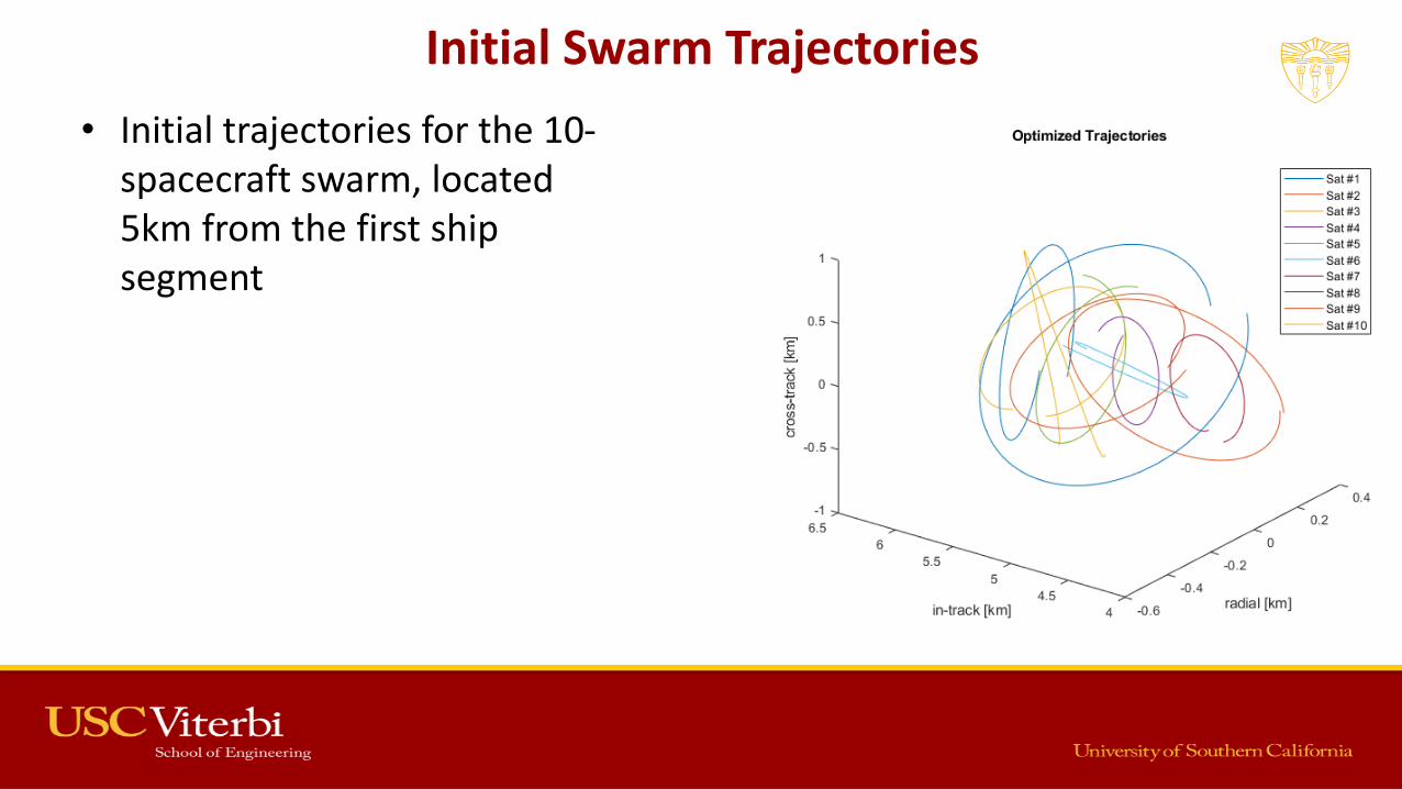
Initial Swarm Trajectories
• Initial trajectories for the 10-spacecraft swarm, located 5km from the first ship segment

Transfer Trajectories
• Five spacecraft break off from swarm to go and rendezvous with the five ship segments.
• Trajectories computed using a two-stage RPO process, implementing a Kalman filter to account for drift and injection errors
• Uses 4.6m/s of ∆V

Transfer Trajectories
• Upon capturing the ship segments, the following trajectories were plotted to return all the segments to the construction site
• Uses 8.38m/s of ∆V

Construction Zone Trajectories
• Meanwhile, the remaining five spacecraft that did not go to retrieve the segments move into observer positions in the construction zone
Death of a Spacecraft
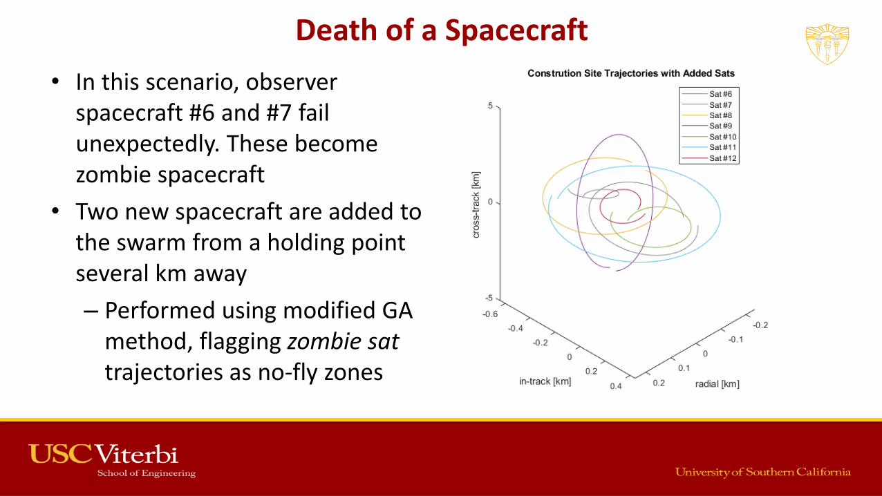
• In this scenario, observer spacecraft #6 and #7 fail unexpectedly. These become zombie spacecraft
• Two new spacecraft are added to the swarm from a holding point several km away
– Performed using modified GA method, flagging zombie sattrajectories as no-fly zones
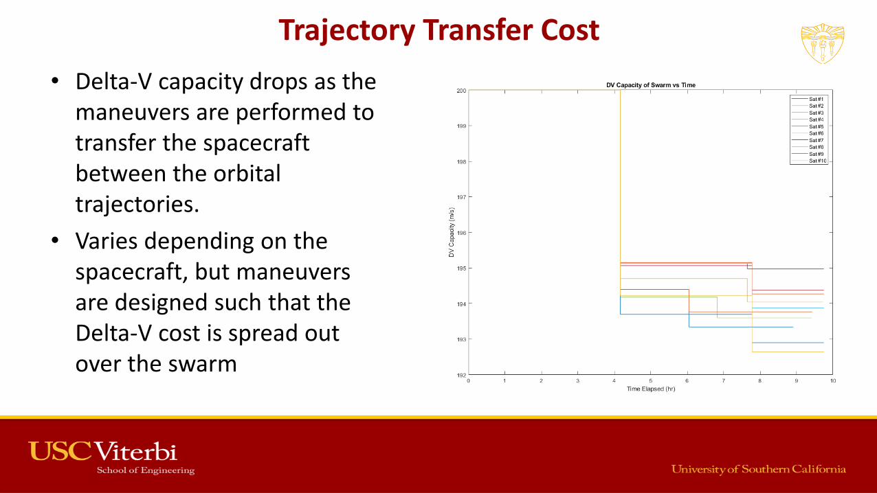
Trajectory Transfer Cost
• Delta-V capacity drops as the maneuvers are performed to transfer the spacecraft between the orbital trajectories.
• Varies depending on the spacecraft, but maneuvers are designed such that the Delta-V cost is spread out over the swarm

Trajectory Maintenance
• Stationkeeping maneuvers must be performed periodically to maintain these trajectories
– Account for accumulated errors causing significant drift
• Uses 27.38m/s over 10-day period for this ten-spacecraft swarm
• Swarm GA method is able toaccount for either chemical or electric propulsion, though chemical is assumed for these simulations due to higher impulse.
– GEO cases covered later will use EP, using method of patched splines to approximate constant thrust trajectories

Behavioral Stresses
of the System

Consider Edge Cases for Swarm Framework
• Probing of edge cases is required to determine the operational regime of these swarm algorithms
• Considers:
– Unexpected Loss of Vehicle
– Responses to Dynamic Construction Environments
– Collision Avoidance Schemes
Depiction of Covariance Ellipses on Swarm

Unexpected Loss of Vehicle
• Offline swarm member = zombie satellite
– Assigned a 50m safety corridor as keep-out zone
• Trajectories are passively safe
– Short term collision avoidance guaranteed
• Will hinder other swarm spacecraft until resolved or removed
Depiction of Covariance Ellipses on Swarm

Response to Dynamic Construction Environment
• As structure is aggregated, the swarm will need to steadily grow in size to match
– Sphere shows keep-out zone for aggregation
– If structure grows beyond the sphere, the keep-out zone and swarm must expand
• Problem is to determine what growth factor to apply to swarm when the structure exceeds the boundary Depiction of Covariance Ellipses on Swarm

Response to Dynamic Construction Environment
• Simulations were run for growth rates from 1.01 – 2.00 to determine the optimal value
– Results show that DV can be minimized at 1.01 or 1.75 growth rate
• Discard anything less than 1.2, as this results in excessive computational and operational overhead.
– R = 1.75 is optimal Depiction of Covariance Ellipses on Swarm

Collision Avoidance Schemes
• SFKF is great for predicting collisions, but a system is needed to rectify the problem
• A hierarchical set of collision avoidance schemes were developed, expanding on existing systems and practices [9-12]
Depiction of Covariance Ellipses on Swarm
[9] GL Slater, SM Byram, and TW Williams. Collision Avoidance for Satellites in Formation Flight. Journal of Guidance, Control, and Dynamics, 29(5):1140–1146, 2006[10] Uriot et. al. Spacecraft Collision Avoidance Challenge: Design and Results of a Machine Learning Competition. arXivPreprint arXiv:2008.03069, 2020.[11] Ti Chen, Hao Wen, Haiyan Hu, and Dongping Jin. Output Consensus and Collision Avoidance of a Team of Flexible Spacecraft for on-Orbit Autonomous Assembly. Acta Astronautica, 121:271–281, 2016.[12] Noelia Sanchez-Ortiz, Miguel Bell o-Mora, and Heiner Klinkrad. Collision Avoidance Manoeuvres During Spacecraft Mission Lifetime: Risk Reduction and Required DV. Advances in Space Research
Credit: Busy-Virat et al., 2018

Collision Avoidance Schemes
Depiction of Covariance Ellipses on Swarm
• Simplest Method
• Alter trajectories slightly for involved spacecraft, and recompute
Offset Trajectory Generation
• Similar to first method
• Applied to directly adjacent spacecraft as well
Extended Scope Offset Trajectories
• More resource intensive
• Computes continuous-thrust trajectory along a spline, connecting two safe points on either side of the collision zone
Non-Keplerian Patched Trajectories
• Apply first method over a shorter time period (<24hrs)
• Will provide a stopgap for ground operators to solve the issue
Stopgap Trajectory• If no solution is
found, eject the spacecraft to save the rest of the swarm
• Push out at least 10km from swarm
Removal from Swarm
[13] Yoonsoo Kim, Mehran Mesbahi, and Fred Y Hadaegh. Multiple-Spacecraft Reconfiguration Through Collision Avoidance, Bouncing, and Stalemate. Journal of Optimization Theory and Applications, 122(2):323–343, 2004
*Similar toBouncing Ball method [13]

Application to GEO
Slot Sharing
Application to GEO Co-location
• Although the algorithms were created to solve the problem of in-space manufacturing using swarms of dozens or hundreds of spacecraft, an interesting subproblem was found to be applying this to Geostationary spacecraft sharing the same slot
Credit: Northrop Grumman
• Results using 4-spacecraft co-location shows lower ∆V usage than existing literature values for GEO co-location
• Reached out to engineers in industry to get real-world data to test against.

Comparison to Existing Spacecraft
• Received data showing ∆V usage over 1yr of ops for four spacecraft co-located in GEO
Credit: Northrop Grumman
Credit: Airbus Defense & Space
Test Case – 4 SC Sharing GEO Slot
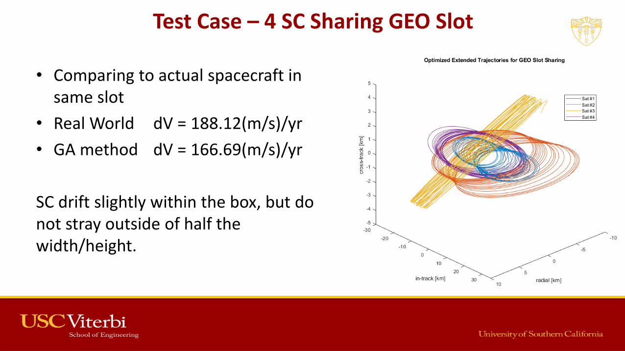
• Comparing to actual spacecraft in same slot
• Real World dV = 188.12(m/s)/yr
• GA method dV = 166.69(m/s)/yr
SC drift slightly within the box, but do not stray outside of half the width/height.

Future Research
Paths
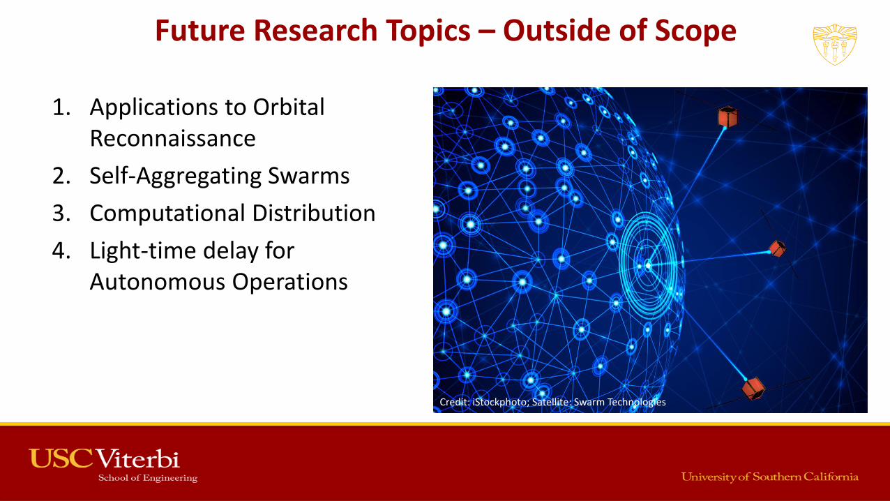
Future Research Topics – Outside of Scope
1. Applications to Orbital Reconnaissance
2. Self-Aggregating Swarms
3. Computational Distribution
4. Light-time delay for Autonomous Operations
Credit: iStockphoto; Satellite: Swarm Technologies

Orbital Reconnaissance
• Can apply swarm trajectories to orbital reconnaissance
• An interesting use-case is mapping and analysis of small celestial bodies, such as asteroids and comets
– If one member of the swarm fails, the entire mission is not lost
Depiction of Covariance Ellipses on Swarm
Swarm trajectories around asteroid 433 Eros

Self-Aggregating Swarms
• Similar toswarm in-space manufacturing
Depiction of Covariance Ellipses on SwarmCredit: Novawurks
Credit: Novawurks

Scaling with Number of Spacecraft
• Conjunction de-confliction takes the most wall-time
• Scales as O(n2)
• Runtime also depends on pseudo-random initial conditions
– Test cases use averages over 100 trial runs for each swarm size
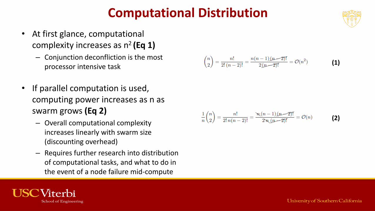
Computational Distribution
• At first glance, computational complexity increases as n2 (Eq 1)– Conjunction deconfliction is the most
processor intensive task
• If parallel computation is used, computing power increases as n as swarm grows (Eq 2)– Overall computational complexity
increases linearly with swarm size (discounting overhead)
– Requires further research into distribution of computational tasks, and what to do in the event of a node failure mid-compute Depiction of Covariance Ellipses on Swarm
(1)
(2)

Parallel Computing
• Conjunction de-confliction takes the most wall-time
– Sped up using parallel computing
• Slope is 1.15
• Data gathered using USC CARC resources

Light-Time Delays
• If light-delay plays a factor in communications, then the swarm cannot rely on ground intervention– Greater autonomy is
needed to solve problems on-the-fly
Depiction of Covariance Ellipses on SwarmCredit: Airbus Defense & Space

Summary &
Conclusions

Summary of Dissertation
1. Created a novel method for swarm trajectory generation using Genetic Algorithms
2. Created a method for optimized aggregation, in close proximity to a growing structure
3. Implemented SFKF for swarm trajectory maintenance
Depiction of Covariance Ellipses on Swarm
4. Explored scenarios for in-space manufacturing
5. Explored applications to GEO slot-sharing
6. Demonstrated using parallel computing the benefits for on-board computational load balancing
7. Increased the state of the art of swarm ops from Class 2 to Class 3.5
Conclusions
• Swarm configurations can enable in-space manufacturing, while maintaining safe and collision-free trajectories
• SFKF, coupled with the Patched RPO method, can be used to maintain trajectories, accounting for unexpected anomalies
Depiction of Covariance Ellipses on Swarm
• Analysis of behavioral stresses identified the operational regime of the GA swarm framework
• Example scenarios demonstrated how the trajectory generation and maintenance can be combined to control swarms of spacecraft
– A novel contribution to the field of Astronautical Engineering

Thank You!
Credit: xkcd / Randall Munroe
Recommended