1
Aircraft Equations of Motion: Translation and Rotation
Robert Stengel, Aircraft Flight Dynamics, MAE 331, 2018
Copyright 2018 by Robert Stengel. All rights reserved. For educational use only.http://www.princeton.edu/~stengel/MAE331.html
http://www.princeton.edu/~stengel/FlightDynamics.html
Lockheed F-104
• What use are the equations of motion?• How is the angular orientation of the
airplane described?• What is a cross-product-equivalent matrix?• What is angular momentum?• How are the inertial properties of the
airplane described?• How is the rate of change of angular
momentum calculated?
Learning Objectives
Reading:Flight Dynamics
155-161
1
Review Questions§ What characteristic(s) provide maximum gliding
range?§ Do gliding heavy airplanes fall out of the sky faster
than light airplanes?§ Are the factors for maximum gliding range and
minimum sink rate the same?§ How does the maximum climb rate vary with altitude?§ What are “energy height” and “specific excess
power”?§ What is an “energy climb”?§ How is the “maneuvering envelope” defined?§ What factors determine the maximum steady turning
rate?2

2
Dynamic Systems
Dynamic Process: Current state depends on prior statex = dynamic state u = input w = exogenous disturbancep = parametert or k = time or event index
Observation Process: Measurement may contain error or be incompletey = output (error-free)z = measurementn = measurement error
Sensors
Actuators
3
dx(t)dt
= f x(t),u(t),w(t),p(t),t[ ]y t( ) = h x(t),u(t)[ ]z t( ) = y t( ) + n t( )
Ordinary Differential Equations Fall Into 4 Categories
dx(t)dt
= f x(t),u(t),w(t)[ ]
dx(t)dt
= f x(t),u(t),w(t),p(t),t[ ] dx(t)dt
= F(t)x(t) +G(t)u(t) + L(t)w(t)
dx(t)dt
= Fx(t) +Gu(t) + Lw(t)
4

3
• Nonlinear equations of motion– Compute �exact� flight paths and
motions• Simulate flight motions• Optimize flight paths• Predict performance
– Provide basis for approximate solutions
• Linear equations of motion– Simplify computation of
flight paths and solutions– Define modes of motion– Provide basis for control
system design and flying qualities analysis
What Use are the Equations of Motion?
dx(t)dt
= f x(t),u(t),w(t),p(t),t[ ]
dx(t)dt
= Fx(t) +Gu(t) + Lw(t)
5
Examples of Airplane Dynamic System Models
• Nonlinear, Time-Varying– Large amplitude motions– Significant change in mass
• Nonlinear, Time-Invariant– Large amplitude motions– Negligible change in mass
• Linear, Time-Varying– Small amplitude motions– Perturbations from a
dynamic flight path
• Linear, Time-Invariant– Small amplitude motions– Perturbations from an
equilibrium flight path
6

4
Translational Position
7
Position of a ParticleProjections of vector magnitude on three axes
r =xyz
⎡
⎣
⎢⎢⎢
⎤
⎦
⎥⎥⎥= r
cosδ x
cosδ y
cosδ z
⎡
⎣
⎢⎢⎢⎢
⎤
⎦
⎥⎥⎥⎥
8
cosδ x
cosδ y
cosδ z
⎡
⎣
⎢⎢⎢⎢
⎤
⎦
⎥⎥⎥⎥
= Direction cosines

5
Cartesian Frames of Reference• Two reference frames of interest
– I: Inertial frame (fixed to inertial space)– B: Body frame (fixed to body)
Common convention (z up) Aircraft convention (z down)
• Translation– Relative linear positions of origins
• Rotation– Orientation of the body frame with
respect to the inertial frame
9
Measurement of Position in Alternative Frames - 1
• Two reference frames of interest– I: Inertial frame (fixed to
inertial space)– B: Body frame (fixed to body)
• Differences in frame orientations must be taken into account in adding vector components
r =xyz
⎡
⎣
⎢⎢⎢
⎤
⎦
⎥⎥⎥
rparticle = rorigin + Δrw.r .t .origin
Inertial-axis view
Body-axis view10

6
Measurement of Position in Alternative Frames - 2
rparticleI = rorigin−BI +HBI ΔrB
Inertial-axis view
Body-axis view
rparticleB = rorigin−IB +H IBΔrI
11
Rotational Orientation
12

7
Direction Cosine Matrix
H IB =
cosδ11 cosδ 21 cosδ 31cosδ12 cosδ 22 cosδ 32cosδ13 cosδ 23 cosδ 33
⎡
⎣
⎢⎢⎢
⎤
⎦
⎥⎥⎥
• Projections of unit vector components of one reference frame on another
• Rotational orientation of one reference frame with respect to another
• Cosines of angles between each I axis and each B axis
rB = H IBrI
13
Properties of the Rotation Matrix
Orthonormal transformationAngles between vectors are preserved
Lengths are preserved
rI = rB ; s I = sB∠(rI ,s I ) = ∠(rB ,sB ) = xdeg
r s
14
H IB =
cosδ11 cosδ 21 cosδ 31cosδ12 cosδ 22 cosδ 32cosδ13 cosδ 23 cosδ 33
⎡
⎣
⎢⎢⎢
⎤
⎦
⎥⎥⎥I
B
=h11 h12 h13h21 h22 h23h31 h32 h33
⎡
⎣
⎢⎢⎢
⎤
⎦
⎥⎥⎥I
B
rB = H IBrI sB = H I
Bs I

8
Euler Angles
15
ψ : Yaw angleθ : Pitch angleφ : Roll angle
• Body attitude measured with respect to inertial frame• Three-angle orientation expressed by sequence of
three orthogonal single-angle rotations
Inertial⇒ Intermediate1 ⇒ Intermediate2 ⇒ Body
• 24 (�12) possible sequences of single-axis rotations
• Aircraft convention: 3-2-1, z positive down
Euler Angles Measure the Orientation of One Frame with Respect to the Other
• Conventional sequence of rotations from inertial to body frame– Each rotation is about a single axis– Right-hand rule – Yaw, then pitch, then roll– These are called Euler Angles
Yaw rotation (ψ) about zI Pitch rotation (θ) about y1 Roll rotation (ϕ) about x2
Other sequences of 3 rotations can be chosen; however, once sequence is chosen, it must be retained 16

9
Reference Frame Rotation from Inertial to Body: Aircraft Convention (3-2-1)
Yaw rotation (ψ) about zI axis
Pitch rotation (θ) about y1 axis
Roll rotation (ϕ) about x2 axis
xyz
⎡
⎣
⎢⎢⎢
⎤
⎦
⎥⎥⎥1
=cosψ sinψ 0−sinψ cosψ 00 0 1
⎡
⎣
⎢⎢⎢
⎤
⎦
⎥⎥⎥
xyz
⎡
⎣
⎢⎢⎢
⎤
⎦
⎥⎥⎥I
=xI cosψ + yI sinψ−xI sinψ + yI cosψ
zI
⎡
⎣
⎢⎢⎢
⎤
⎦
⎥⎥⎥
xyz
⎡
⎣
⎢⎢⎢
⎤
⎦
⎥⎥⎥2
=cosθ 0 −sinθ0 1 0sinθ 0 cosθ
⎡
⎣
⎢⎢⎢
⎤
⎦
⎥⎥⎥
xyz
⎡
⎣
⎢⎢⎢
⎤
⎦
⎥⎥⎥1
xyz
⎡
⎣
⎢⎢⎢
⎤
⎦
⎥⎥⎥B
=1 0 00 cosφ sinφ0 −sinφ cosφ
⎡
⎣
⎢⎢⎢
⎤
⎦
⎥⎥⎥
xyz
⎡
⎣
⎢⎢⎢
⎤
⎦
⎥⎥⎥2 17
r1 = H I1rI
r2 = H12r1 = H1
2H I1⎡⎣ ⎤⎦rI = H I
2rI
rB = H2Br2 = H2
BH12H I
1⎡⎣ ⎤⎦rI = H IBrI
The Rotation Matrix
H IB(φ,θ ,ψ)=H2
B(φ)H12 (θ )H I
1 (ψ)
The three-angle rotation matrix is the product of 3 single-angle rotation matrices:
=1 0 00 cosφ sinφ0 −sinφ cosφ
⎡
⎣
⎢⎢⎢
⎤
⎦
⎥⎥⎥
cosθ 0 −sinθ0 1 0sinθ 0 cosθ
⎡
⎣
⎢⎢⎢
⎤
⎦
⎥⎥⎥
cosψ sinψ 0−sinψ cosψ 00 0 1
⎡
⎣
⎢⎢⎢
⎤
⎦
⎥⎥⎥
an expression of the Direction Cosine Matrix18
=cosθ cosψ cosθ sinψ −sinθ
−cosφ sinψ + sinφ sinθ cosψ cosφ cosψ + sinφ sinθ sinψ sinφ cosθsinφ sinψ + cosφ sinθ cosψ −sinφ cosψ + cosφ sinθ sinψ cosφ cosθ
⎡
⎣
⎢⎢⎢
⎤
⎦
⎥⎥⎥
10
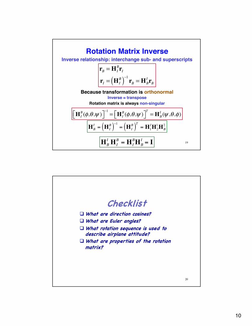
Rotation Matrix InverseInverse relationship: interchange sub- and superscripts
Because transformation is orthonormalInverse = transpose
Rotation matrix is always non-singular
HBI = H I
B( )−1 = H IB( )T = H1
IH21HB
2
HBI H I
B = H IBHB
I = I 19
H IB(φ,θ ,ψ )⎡⎣ ⎤⎦
−1= H I
B(φ,θ ,ψ )⎡⎣ ⎤⎦T= HB
I (ψ ,θ ,φ)
rB = H IBrI
rI = H IB( )−1 rB = HB
I rB
Checklistq What are direction cosines?q What are Euler angles?q What rotation sequence is used to
describe airplane attitude?q What are properties of the rotation
matrix?
20

11
Angular Momentum
21
Angular Momentum of a Particle
• Moment of linear momentum of differential particles that make up the body– (Differential masses) x components of the
velocity that are perpendicular to the moment arms
• Cross Product: Evaluation of a determinant with unit vectors (i, j, k)along axes, (x, y, z) and (vx, vy, vz) projections on to axes
r × v =i j kx y zvx vy vz
= yvz − zvy( ) i + zvx − xvz( ) j + xvy − yvx( )k
dh = r × dm v( ) = r × vm( )dm= r × vo +ω × r( )⎡⎣ ⎤⎦dm
ω =
ω x
ω y
ω z
"
#
$$$$
%
&
''''
22

12
Cross-Product-Equivalent Matrix
r × v =i j kx y zvx vy vz
= yvz − zvy( ) i + zvx − xvz( ) j + xvy − yvx( )k
=
yvz − zvy( )zvx − xvz( )xvy − yvx( )
#
$
%%%%%
&
'
(((((
= rv =0 −z yz 0 −x−y x 0
#
$
%%%
&
'
(((
vxvyvz
#
$
%%%%
&
'
((((
Cross-product-equivalent matrix
r =0 −z yz 0 −x−y x 0
"
#
$$$
%
&
'''
Cross product
23
Angular Momentum of the Aircraft• Integrate moment of linear momentum of differential particles over the body
h = r × vo +ω × r( )⎡⎣ ⎤⎦dmBody∫ = r × v( )ρ(x, y, z)dxdydz
zmin
zmax
∫ymin
ymax
∫xmin
xmax
∫ =
hxhyhz
⎡
⎣
⎢⎢⎢⎢
⎤
⎦
⎥⎥⎥⎥
ρ(x, y, z) = Density of the body
h = r × vo( )dmBody∫ + r × ω × r( )⎡⎣ ⎤⎦dm
Body∫
= 0 − r × r × ω( )⎡⎣ ⎤⎦dmBody∫
= − r × r( )dm × ωBody∫ ≡ − !r!r( )dmω
Body∫
• Choose the center of mass as the rotational centerSupermarine Spitfire
24

13
Location of the Center of Mass
rcm =1m
rdmBody∫ = rρ(x, y, z)dxdydz
zmin
zmax
∫ymin
ymax
∫xmin
xmax
∫ =
xcmycmzcm
#
$
%%%
&
'
(((
25
The Inertia Matrix
26

14
The Inertia Matrix
h = − !r !r ω dm
Body∫ = − !r !r dm
Body∫ ω = Iω
Inertia matrix derives from equal effect of angular rate on all particles of the aircraft
I = − !r !r dmBody∫ = −
0 −z yz 0 −x−y x 0
⎡
⎣
⎢⎢⎢
⎤
⎦
⎥⎥⎥
0 −z yz 0 −x−y x 0
⎡
⎣
⎢⎢⎢
⎤
⎦
⎥⎥⎥dm
Body∫
=(y2 + z2 ) −xy −xz
−xy (x2 + z2 ) −yz
−xz −yz (x2 + y2 )
⎡
⎣
⎢⎢⎢⎢
⎤
⎦
⎥⎥⎥⎥
dmBody∫
ω =
ω x
ω y
ω z
"
#
$$$$
%
&
''''
where
27
Moments and Products of Inertia
Inertia matrix
I =(y2 + z2 ) −xy −xz
−xy (x2 + z2 ) −yz
−xz −yz (x2 + y2 )
⎡
⎣
⎢⎢⎢⎢
⎤
⎦
⎥⎥⎥⎥
dmBody∫ =
I xx −I xy −I xz
−I xy I yy −I yz
−I xz −I yz I zz
⎡
⎣
⎢⎢⎢⎢
⎤
⎦
⎥⎥⎥⎥
• Moments of inertia on the diagonal• Products of inertia off the diagonal
I xx 0 00 I yy 0
0 0 I zz
⎡
⎣
⎢⎢⎢⎢
⎤
⎦
⎥⎥⎥⎥
• If products of inertia are zero, (x, y, z) are principal axes --->
• All rigid bodies have a set of principal axes
Ellipsoid of Inertia
I xxx2 + I yyy
2 + I zzz2 = 1
28

15
Inertia Matrix of an Aircraft with Mirror Symmetry
I =(y2 + z2 ) 0 −xz
0 (x2 + z2 ) 0−xz 0 (x2 + y2 )
⎡
⎣
⎢⎢⎢⎢
⎤
⎦
⎥⎥⎥⎥
dmBody∫ =
I xx 0 −I xz
0 I yy 0
−I xz 0 I zz
⎡
⎣
⎢⎢⎢⎢
⎤
⎦
⎥⎥⎥⎥
Nose high/low product of inertia, Ixz
North American XB-70
Nominal ConfigurationTips folded, 50% fuel, W = 38,524 lb
[email protected] cI xx = 1.8 ×10⁶ slug-ft2
I yy = 19.9 ×10⁶ slug-ft2
I xx = 22.1×10⁶ slug-ft2
I xz = −0.88 ×10⁶ slug-ft2 29
Checklistq How is the location of the center of
mass found?q What is a cross-product-equivalent
matrix?q What is the inertia matrix?q What is an ellipsoid of inertia?q What does the “nose-high” product of
inertia represent?
30

16
Technology of World War II Aviation• 1938-45: Analytical and
experimental approach to design– Many configurations designed and
flight-tested – Increased specialization; radar,
navigation, and communication– Approaching the "sonic barrier�
• Aircraft Design– Large, powerful, high-flying aircraft– Turbocharged engines– Oxygen and Pressurization
Spitfire
P-51D
B-17
Historical Factoids
31
Power Effects on Stability and Control
• Brewster Buffalo: over-armored and under-powered
• During W.W.II, the size of fighters remained about the same, but installed horsepower doubled (F4F vs. F8F)
• Use of flaps means high power at low speed, increasing relative significance of thrust effects Grumman Bearcat F8F
GrummanWildcat F4F
Brewster Buffalo F2A
32

17
World War II Carrier-Based Airplanes
• Takeoff without catapult, relatively low landing speed http://www.youtube.com/watch?v=4dySbhK1vNk
• Tailhook and arresting gear• Carrier steams into wind• Design for storage (short tail length, folding
wings) affects stability and control
Chance-Vought F4U Corsair
Grumman TBF
Douglas TBD
F4U
33
Multi-Engine Aircraft of World War II
• Large W.W.II aircraft had unpowered controls:– High foot-pedal force– Rudder stability problems
arising from balancing to reduce pedal force
• Severe engine-out problem for twin-engine aircraft
Boeing B-17 Boeing B-29Consolidated B-24
Douglas A-26
North American B-25
Martin B-26
34

18
WW II Military Flying BoatsSeaplanes proved useful during World War II
Lockheed PBY
Catalina
Martin PBM Mariner
Martin PB2M Mars
Boeing XPBB Sea Ranger
Saunders-Roe SR.36 Lerwick
Grumman JRF-1 Goose
35
Rate of Change of Angular Momentum
36

19
Newton�s 2nd Law, Applied to Rotational Motion
In inertial frame, rate of change of angular momentum = applied moment (or torque), M
dhdt
=d Iω( )dt
= dIdt
ω + I dωdt
37
= !Iω + I !ω =M =
mx
my
mz
⎡
⎣
⎢⎢⎢⎢
⎤
⎦
⎥⎥⎥⎥
Angular momentum and rate vectors are not necessarily
aligned
h = Iω
Angular Momentum and Rate
38

20
How Do We Get Rid of dI/dt in the Angular Momentum Equation?
• Dynamic equation in a body-referenced frame– Inertial properties of a constant-mass, rigid body are
unchanging in a body frame of reference– ... but a body-referenced frame is �non-Newtonian�
or �non-inertial�– Therefore, dynamic equation must be modified for
expression in a rotating frame
d Iω( )dt
= !Iω + I !ω
Chain Rule ... and in an inertial frame
!I ≠ 0
39
Angular Momentum Expressed in Two
Frames of Reference• Angular momentum and rate
are vectors– Expressed in either the inertial
or body frame– Two frames related algebraically
by the rotation matrix
hB t( ) = H IB t( )hI t( ); hI t( ) = HB
I t( )hB t( )
ω B t( ) = H IB t( )ω I t( ); ω I t( ) = HB
I t( )ω B t( )40

21
Vector Derivative Expressed in a Rotating Frame
Chain Rule
Consequently, the 2nd term is
hI = HB
I hB + HBI hB
Effect of body-frame rotation
Rate of change expressed in body frameAlternatively
hI = HB
I hB +ω I × hI = HBI hB + ω IhI
ω =
0 −ω z ω y
ω z 0 −ω x
−ω y ω x 0
#
$
%%%%
&
'
((((
... where the cross-product equivalent matrix of angular rate is
HBI hB = ω IhI = ω IHB
I hB
41
External Moment Causes Change in Angular Rate
!hB = H IB !hI + !H I
BhI = H IB !hI − ω B × hB = H I
B !hI − "ω BhB= H I
BM I − "ω BIBω B =MB − "ω BIBω B
Positive rotation of Frame B w.r.t. Frame A is a negative rotation of
Frame A w.r.t. Frame B
M I =
mx
my
mz
!
"
####
$
%
&&&&I
; MB =H IBM I =
mx
my
mz
!
"
####
$
%
&&&&B
=LMN
!
"
###
$
%
&&&
Moment = torque = force x moment arm
In the body frame of reference, the angular momentum change is
42

22
Rate of Change of Body-Referenced Angular Rate due to
External Moment
For constant body-axis inertia matrix
!hB = H IB !hI + !H I
BhI = H IB !hI − ω B × hB
= H IB !hI − "ω BhB = H I
BM I − "ω BIBω B
=MB − "ω BIBω B
In the body frame of reference, the angular momentum change is
!ω B = IB−1 MB − "ω BIBω B( )Consequently, the differential equation for angular rate of change is
!hB = IB !ω B =MB − "ω BIBω B
43
Checklistq Why is it inconvenient to solve momentum rate
equations in an inertial reference frame?q Are angular rate and momentum vectors
aligned?q How are angular rate equations transformed
from an inertial to a body frame?
44

23
Next Time:Aircraft Equations of Motion:
Flight Path ComputationReading:
Flight Dynamics161-180
45
How is a rotating reference frame described in an inertial reference frame?
Is the transformation singular?What adjustments must be made to expressions for forces and
moments in a non-inertial frame?How are the 6-DOF equations implemented in a computer?
Damping effects
Learning Objectives
Supplemental Material
46

24
Moments and products of inertia tabulated for geometric shapes with uniform density
Construct aircraft moments and products of inertia from components using parallel-axis theorem
Model in CREO, etc.
47
Moments and Products of Inertia(Bedford & Fowler)
Recommended