Copyright ©2015 Slope Indicator Company. All Rights Reserved.
This equipment should be installed, maintained, and operated by technically qualified personnel. Any errors or omissions in data, or the interpretation of data, are not the responsibility of Slope Indicator Company. The information herein is subject to change without notification.
This document contains information that is proprietary to Slope Indicator company and is subject to return upon request. It is transmitted for the sole purpose of aiding the transaction of business between Slope Indi-cator Company and the recipient. All information, data, designs, and drawings contained herein are propri-etary to and the property of Slope Indicator Company, and may not be reproduced or copied in any form, by photocopy or any other means, including disclosure to outside parties, directly or indirectly, without permis-sion in writing from Slope Indicator Company.
SLOPE INDICATOR12123 Harbour Reach DriveMukilteo, Washington, USA, 98275Tel: 425-493-6200 Fax: 425-493-6250E-mail: [email protected]: www.slopeindicator.com
Rod Extensometer51836499

Rod Extensometer 2015/4/20
Contents
Components & Planning . . . . . . . . . . . .1
Installation Overview . . . . . . . . . . . . . . .2
Assembly of Steel Rods . . . . . . . . . . . . .4
Assembly of Mechanical Head. . . . . . .7
Assembly of Electric Head . . . . . . . . . 10
Wiring the Electric Head. . . . . . . . . . . 15
Reading VW Sensors . . . . . . . . . . . . . . 17
Reading Potentiometers . . . . . . . . . . 19
Data Reduction . . . . . . . . . . . . . . . . . . . 21
Appendix 1: Packer Anchors. . . . . . . 25
Appendix 2: Hydraulic Anchors . . . . 27

Rod Extensometer 2015/4/20 1
Components and PlanningReference Head: Measurements are made at the ref-
erence head. Mechanical heads are read with a depth micrometer. Electric heads have sensors.
Telescoping Joint A telescoping joint sits between the reference head and the top of the rods. It allows adjustments in the position of the reference head.
Rods Fiberglass rods are supplied in continuous lengths. Steel rods are supplied in 10 foot lengths.
ProtectiveTubing or Pipe
Fiberglass rods are encased in con-tinuous lengths of plastic tubing. Steel rods are encased in plastic pipe supplied in 10 foot lengths.
Anchors Anchors may be groutable, hydraulic, or packer type.
ImportantMeasurements
P, R, and A.
The drawing at right shows three measurements that are important for assembly for steel rods. Fiber-glass rods are preassembled so measurements are not required.
A is Anchor depth, the distance from the top of the reference head to the top of the anchor.
R is Rod length. Rod length should be A - 5 inches (127 mm). Adjust R only at the top length of rod.
P is Pipe length, which should be R – 17 inches (430 mm). Cut off 10 inches (254 mm) from the bottom pipe (the pipe nearest the anchor). This staggers ends of rod and pipe for easier assembly.
P R A
ReferenceHead Cover
Reference Head
Rod
Telescoping Joint
Protective Pipe
Anchor

Rod Extensometer 2015/4/20 2
Installation Overview
Introduction Details of the installation are usually determined by site requirements. Here, we present general information about installation, since details are often site specific. Assembly and wiring are discussed later.
BoreholeRequirements
The rod extensometer is designed for boreholes that are 60 to 96 mm in diameter (2.4 to 3.8 inches). Boreholes should be drilled about 1 meter (3 feet) deeper than the deepest anchor.
Assembly Fiberglass Rod Extensometers: Fiberglass rod extensometers are shipped pre-assembled and coiled, so no on-site assembly is required. The rods must be uncoiled carefully, then inspect the extensometer: • Verify that anchors are firmly connected to the rods and protective
tubing. The connection is similar to that shown for steel rods.• Verify that sensor adaptors are firmly connected to the other end of
the rods.
Steel Rod Extensometers: Steel rod extensometers must be assembled on site. When space allows, pre-assemble the extensometer on the sur-faceAssemble the complete steel rod extensometer (except for sensors) and attach grout tubing.Park a pick-up truck near the borehole, then position your installers so that they lift the extensometer up and over the truck and down into the borehole. By lifting the extensometer over the truck, you can maintain a minimum bending radius of 3 meters or 10 feet to avoid permanently bending the rods.
When space is tight, it is necessary to assemble the extensometer as it is installed downhole. Downhole assembly requires careful organization. Sometimes it is possible to assemble and install each anchor and rod independently, starting with the deepest anchor. A safety rope should be attached to each anchor. Grout tubing can also be attached to the anchors.
Grouting Use the grout mix specified by the site engineer. When grouting through long lengths of polyethylene tubing, first pump water through the tubing to minimize friction.
GroutingDown-Holes
A single grout tube is usually adequate for vertical and inclined down-holes. Tape the end of the tube to the protective pipe near the bottom anchor. Tubing will be drawn into the borehole as the extensometer is installed. Sometimes a second, shorter grout tube is taped to a pipe about half-way down the length of the extensometer. This tube can be used if difficulties arise with the longer tube. When you begin pumping

Rod Extensometer 2015/4/20 3
the grout, pull the grout tube free from the protective pipe. Draw it upwards as the level of grout rises in the borehole.
Grouting Up-Holes Tape a tube to the protective pipe so that it projects beyond the deepest anchor. This will be the vent tube. Tape a second tube just below the deepest anchor. Tape a third tube to the protective pipe about 2 or 3 meters from the borehole collar.
After installing extensometer, Seal the borehole collar with rags soaked in quick-set cement. Then form a plug by pumping quick-set grout into the borehole through the shortest tube. Allow time for the plug to set.
Finally pump grout into the borehole using the longer grout tube. When grout returns via the vent tube, you know the borehole is com-pletely grouted. Fold and tie-off tubes with wire.
Tools and Materials For Steel Rod Extensometers• Measuring tape.• Hacksaw for cutting rod and pipe.• Visegrips for tightening threaded rods and anchors• Allen wrenches (supplied) for various set screws.• PVC solvent cement for pipe joints.
For Steel Rod and Fiberglass Rod Extensometers• Screwdrivers for wiring.• Nylon rope or equivalent, 300 to 400 lb test strength.• Grout tubing, grout mixer/pump, cement for grout• Pull-in anchor and fast-set cement or grout and rags for packing
borehole if installing extensometer in up-holes.• Materials to construct concrete pad at borehole collar.

Rod Extensometer 2015/4/20 4
Assembly of Steel Rods
Connect Rod andProtective Pipe to
Anchor
Required parts: anchor, rod, protective pipe, anchor adapter, rubber sleeve, special pipe coupling. The drawing above shows the groutable anchor. Assembly is nearly the same for hydraulic anchors and packer anchors. See Appendix 1 and 2 for more information.
1. Cut 10 inches (254 mm) off the protective pipe.
2. Screw anchor adapter into anchor.
3. Fit rod into anchor adapter. Tighten set screws.
4. Slide rubber sleeve over anchor adapter.
5. Screw special pipe coupling onto anchor adapter.
6. Glue protective pipe into special pipe coupling.
Skip this chapter if you have fiberglass rods
Rubber Sleeve
Rod
AnchorAdapter
Special Pipe Coupling. Bottom end is threaded.
Anchor
Rod Extensometer 2015/4/20 5
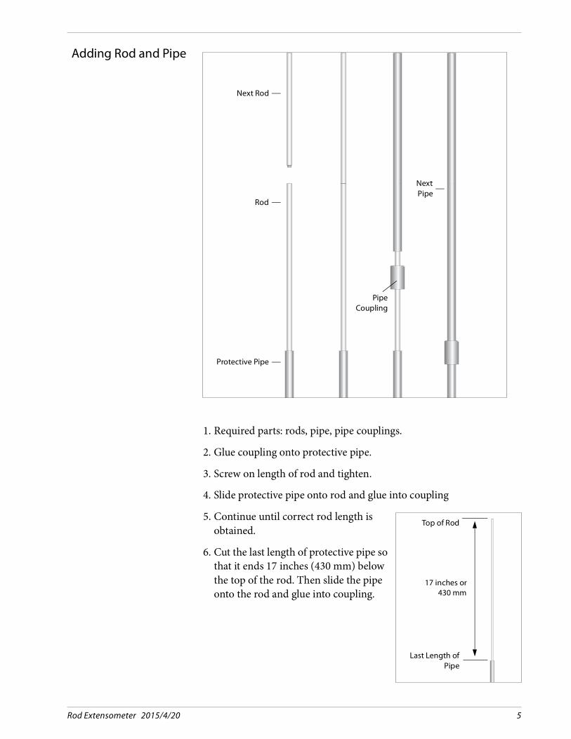
Adding Rod and Pipe
1. Required parts: rods, pipe, pipe couplings.
2. Glue coupling onto protective pipe.
3. Screw on length of rod and tighten.
4. Slide protective pipe onto rod and glue into coupling
5. Continue until correct rod length isobtained.
6. Cut the last length of protective pipe sothat it ends 17 inches (430 mm) belowthe top of the rod. Then slide the pipeonto the rod and glue into coupling.
Protective Pipe
Rod
Next Rod
PipeCoupling
NextPipe
17 inches or430 mm
Top of Rod
Last Length ofPipe

Rod Extensometer 2015/4/20 6
Prepare Top of Rod
1. Required parts: telescoping joint, sensor adapter. The sensor adaptoris used with both the electric and mechanical heads.
2. Slide telescoping joint onto rod. Glue coupling onto protective pipe.
3. Press sensor adapter onto rod. Tighten both set screws.
4. Pull telescoping joint up over sensor adapter.
ProtectivePipe
Rod
TelescopingJoint
SensorAdapter
PullTelescoping
Joint Up

Rod Extensometer 2015/4/20 7
Assembly ofMechanical Reference Head
ComponentsC
• The reference head is split into a top half and a bottom half. The cen-ter hole in the bottom half is threaded to accept all-thread rod. Thecenter hole of the top half has no threads.
• O-rings fit onto the telescoping joints and are clamped between thetop and bottom halves of the reference head. The plug fits intounused positions in the reference head.
• The all-thread rod holds the two halves of the head together• The steel reference plate fits onto the reference head and is held by a
nut.• A flat plastic cover protects the reference plate and is held by a
butterfly nut and washer.
All-Thread Rod
Steel Reference Plate
Reference HeadTop Half
PlugO-Ring
Nut
Butterfly Nutand Washer
Reference HeadBottom Half
Cover
Rod Extensometer 2015/4/20 8
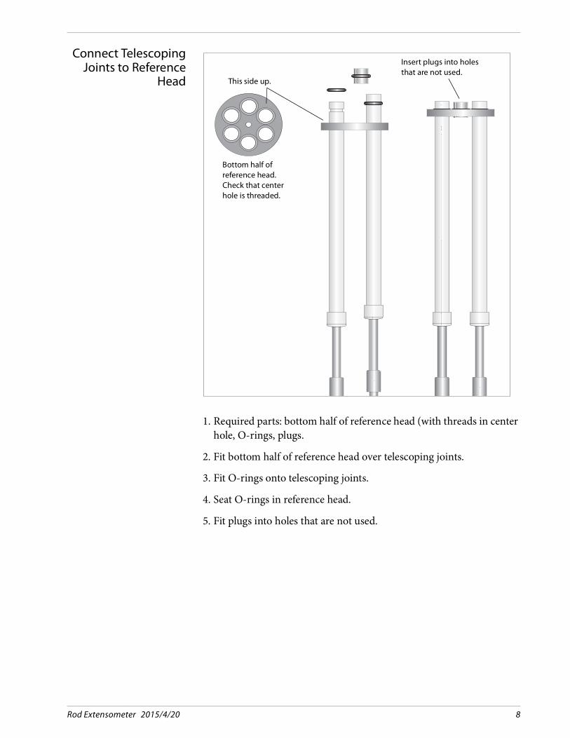
Connect TelescopingJoints to Reference
Head
1. Required parts: bottom half of reference head (with threads in centerhole, O-rings, plugs.
2. Fit bottom half of reference head over telescoping joints.
3. Fit O-rings onto telescoping joints.
4. Seat O-rings in reference head.
5. Fit plugs into holes that are not used.
Bottom half ofreference head. Check that center hole is threaded.
Insert plugs into holes that are not used.
This side up.

Rod Extensometer 2015/4/20 9
Join Top and Bottomof Reference Head
1. Required parts: all thread rod, top half of reference head,steel reference plate, nut, cover, washer, and wingnut.
2. Screw all-thread rod into bottom half of reference head.
3. Fit top half of reference head onto bottom half.
4. Place steel reference plate onto reference head. Fasten with nut.
5. Place cover onto reference plate. Fasten with washer and wingnut.Remove cover to take readings.
DigitalDepth Micrometer
If the installation goes as planned, the distance between the top of the reference surface and the top of each rod will be about 5 inches.
The depth micrometer has a 1 inch (25mm) measurement range. Its range is extended by adding or subtracting extension shafts, which are included.
6. A special foot is supplied with the micrometer to provide a flat con-tact surface. Be sure to use this foot.
All-thread rod
Top half of reference head, steel reference plate, and nut.
Cover, washer, and wingnut

Rod Extensometer 2015/4/20 10
Assembly ofElectric Reference Head
Components ofElectric Reference
Head
C
• The reference head is split into a top half and a bottom half.• O-rings fit onto the telescoping joints and are clamped between the
top and bottom halves of the reference head. The plug fits intounused positions in the reference head.
• The all-thread rod holds the two halves of the head together and alsoholds the cover onto the head.
• The sensor clamp holds sensors onto the reference head.• A two-piece cover is supplied with the head.
Cover
All-Thread Rod
SensorClamp
Reference HeadTop Half
PlugO-Ring
Reference HeadBottom Half
Sealing Washerand Nut
Sealing Washerand Nut

Rod Extensometer 2015/4/20 11
Connect TelescopingJoints to Reference
Head
1. Parts: bottom half of reference head, O-rings, plugs.
2. Fit bottom half of reference head over telescoping joints.
3. Fit O-rings onto telescoping joints.
4. Seat O-rings in reference head.
5. Fit plugs into holes that are not used.
Bottom half ofreference head.
Insert plugs into holes that are not used.
This side up.

Rod Extensometer 2015/4/20 12
Join Top and Bottomof Reference Head
1. Required parts: top half of reference head, all-thread rod,sealing washer and nut, sensor clamps.
2. Fit top half of reference head onto bottom half.
3. Thread nut and washer onto all-thread rod.
4. Screw all-thread rod into reference head.
5. Tighten nut.
6. Screw sensor clamps into reference head. Check that set screws areaccessible with allen wrench.

Rod Extensometer 2015/4/20 13
Temporary Configuration for
Holding Rods During Installation

Rod Extensometer 2015/4/20 14
InstallingVW Sensors
1. Required Parts: VW displacementsensors. Note that installing sensorsis the very last step in the installa-tion process. All grouting and workaround the borehole collar shouldbe finished.
2. Screw sensor shaft into adapter attop of rod.
3. Connect readout to displacementsensor.
4. Move sensor up or down to achievedesired initial reading.
5. Tighten set screws on sensorclamps.
InstallingPotentiometers
1. Potentiometer shaft is fullyextended by a spring. Position ofshaft determines range formeasuring compression or exten-sion.
2. Slide potentiometer into sensorclamp until spring loaded shafttouches sensor adaptor at top ofrod. In this position, potentiometercan measure only compression ofshaft (movement of rod into poten-tiometer body).
3. To allow measurement of extensionof shaft, press potentiometer fartherinto sensor clamp. If sensor adap-tor at top of rod is too far away, youmust replace standard tip with alonger tip.
Rod
VWdisplacement
sensor
SensorClamp
Sensoradapter
Potentiometer
StandardTip
Rod

Rod Extensometer 2015/4/20 15
Wiring the Electric Head
Wiring VW Sensors The table below shows the function and color coding of leadsfrom VW sensors.
Wiring VW Sensors to a12-Conductor Cable
A 12 position terminal strip is supplied with the electric head, which allows connection of up to six sensors to a 12 conductor cable.
Connect VW+ wires to unique terminals. Connect VW- wires to com-mon terminals. Connecting a single RTD temperature sensor is suffi-cient. The table below shows an example of connecting six VW sensors to the terminal strip. The 12-wire cable is Slope Indicator’s part number 50612512.
Function Color Coding of Leads from Sensor
VW + Red Orange
VW - Black White /Orange
Temp + Green Blue
Temp - White White/Blue
Shield Shield Shield
VW Sensor Terminal Strip 12 -Wire Cable
VW1 + 1 Brown
VW2 + 2 Red
VW3 + 3 Orange
VW4 + 4 Green
VW5 + 5 Blue
VW6 + 6 Violet
VW1 - VW2 - VW3 -
7 Yellow
VW4 - VW5-VW6 -
8 Gray
Temp 1 + 9 White
Temp 1- 10 Black

Rod Extensometer 2015/4/20 16
WiringPotentiometers
The table below shows the function and color coding of leadsfrom potentiometers.
Wiring Potentiometers toa 12 Conductor Cable
The scheme below shows how to connect leads from the potentiome-ters to a terminal strip and a 12 conductor cable (part number 50612512 ) inside the extensometer head.
Function Lead Color
Excitation + Black
Excitation - Red
Signal White
Potentiometer Terminal Strip 12 -Wire Cable
Signal 1 1 Brown
Signal 2 2 Red
Signal 3 3 Orange
Signal 4 4 Blue
Signal 5 5 Violet
Signal 6 6 Gray
Excitation +
Jumper 7 and 8 together. Con-nect all black wires to these two terminals in any order
Green
Black
Excitation -
Jumper 9 and 10 together. Connect all red wires to these two terminals in any order.
Yellow
White
Not used Shield

Rod Extensometer 2015/4/20 17
Reading VW Sensors
Introduction These instructions tell how to read VW sensors with Slope Indicator’s portable readouts.
Instructions for reading VW sensors with a Campbell Scientific CR10 can be found at www.slopeindicator.com. Go to Support - Tech Notes and click on the link titled “CR10-VW Sensors.”
VW Data Recorder 1. Connect signal cable to the data recorder. If you must connect to 12 wire cable, refer to the table provided for DataMate MP connections:
2. Choose Hz + Thermistor or Hz + RTD.
3. Select the 1400-3500 Hz range.
4. The recorder displays sensor reading in Hz and a temperature read-ing in degrees C.
VWP Indicator 1. Connect signal cable to the VWP indicator:
2. Select the 1.4-3.50 kHz range with the Sweep key.
3. Select Hz with the Data key. The display shows a reading in Hz.
4. Read the RTD: Select °C with the Data key. Note that the VWP Indi-cator cannot read thermistors.
Binding Posts Wire Colors
VW Orange Red
VW White & Orange Black
TEMP Blue White
TEMP White & Blue Green
SHIELD Shield Shield
Clips Wire Colors Function
Red Orange Red VW
Red White & Orange Black VW
Black Blue White TEMP
Black White & Blue Green TEMP

Rod Extensometer 2015/4/20 18
DataMate MP These instructions tell how to read using the DataMate’s manual mode. Please refer to the DataMate MP manual for details of program mode.
1. Connect signal cable as shown in the table below.
2. Switch on. Press (Manual Mode).
3. Scroll through the list to find “Vibrating Wire Hz.”
4. Press to excite the sensor and display a reading in Hz and a tem-perature reading in degrees C.
Connecting to4-Wire Signal Cables
This table shows how to connect 4-wire signal cables:
Connecting to12-Wire Signal Cables
This table shows Bare Wire Adaptor Connections for 12 wire signal cables. Sensors are read one at a time by swapping the VW+ lead con-nected to terminal 8:
Function Color Coding of VW Sensor Leads
Bare Wire Adapter
Universal Connector
VW + Red Orange 8 H
VW - Black White /Orange 6 F
Temp + Green Blue 5 E
Temp - White White/Blue 7 G
Shield Shield Shield 10 K
VW Sensor 12 -Wire Cable BWA
VW1 + Brown
Read eachVW sensorseparately.
Connect VW+ lead toterminal 8
VW2 + Red
VW3 + Orange
VW4 + Green
VW5 + Blue
VW6 + Violet
VW1 - VW2 - VW3 -
Yellow
6VW4 - VW5-VW6 -
Gray
Temp 1 + White 5
Temp 1- Black 7

Rod Extensometer 2015/4/20 19
Reading Potentiometers
DataMate MP These instructions tell how to read using the DataMate’s manual mode. Please refer to the DataMate MP manual for details of program mode.
1. Connect signal cable as shown in the table below.
2. Switch on. Press (Manual Mode).
3. Scroll through the list to find “Extensometer RO.”
Press to excite the sensor and display a reading in %FS.
Connecting toPotentiometer Leads
The table below shows how to connect leads from potentiometers to the bare wire adaptor. This is probably useful only for testing the sen-sors. You must jumper (make a connection between) two sets of BWA terminals.
Connecting to12-wire Cable
The table below shows how to read potentiometers one at a time by swapping the signal lead at terminal 1 of the bare wire adaptor. The 12 conductor cable is part number 50612512
Function Lead Color BWA
Excitation + Black 6 + 5
Excitation - Red 7 + 8
Signal White 1
Potentiometer 12 -Wire Cable BWA
Signal 1 Brown
Read each potenti-ometer by connect-ing its signal lead to terminal 1.
Signal 2 Red
Signal 3 Orange
Signal 4 Blue
Signal 5 Violet
Signal 6 Gray
Excitation +Green 5
Black 6
Excitation -Yellow 7
White 8
Shield 10

Rod Extensometer 2015/4/20 20
CR10X Data Logger The table below shows an example of wiring a 12 conductor cable with six potentiometers to a CR10X data logger. The 12 conductor cable is Slope Indicator’s part number 50612512.
Potentiometers Terminal Strip 12 -Wire Cable CR10X
Signal 1 1 Brown SE 1
Signal 2 2 Red SE 2
Signal 3 3 Orange SE 3
Excitation - for 1, 2, 3 4 Yellow EX 1
Excitation + for 1, 2, 3 5 Green AG
Signal 4 6 blue SE 3
Signal 5 7 Violet SE 5
Signal 6 8 Gray SE 6
Excitation - for 4, 5, 6 9 White EX 2
Excitation + for 4, 5, 6 10 Black AG

Rod Extensometer 2015/4/20 21
Data Reduction
Overview The readings that we take at the extensometer head are used tocalculate changes in the distance between the reference elevation and each downhole anchor. • If the reference head is located on stable ground, we can calculate
movements of the anchor relative to the head.• If reference head is not stable, then we typically use the deepest
anchor as the reference elevation. In this case, the data must beinverted, so that we can calculate movements of each anchorrelative to the bottom anchor.
1. If you are using the VW or potentiometer displacement sensors, con-vert the reading from each sensor to the desired engineering unit. Noconversions are required if readings are obtained with a micrometer.
2. Organize your data into a table, rows labeled by date, columnslabeled by anchor number.
3. Construct a table of changes by subtracting the initial reading fromsubsequent readings for each anchor. This shows movements relativeto the reference head.
4. If the reference is the deepest anchor, invert the data to show move-ments relative to the deepest anchor. This is done by subtracting thechanges for each anchor from the changes at the deepest anchor.
Rod Extensometer 2015/4/20 22
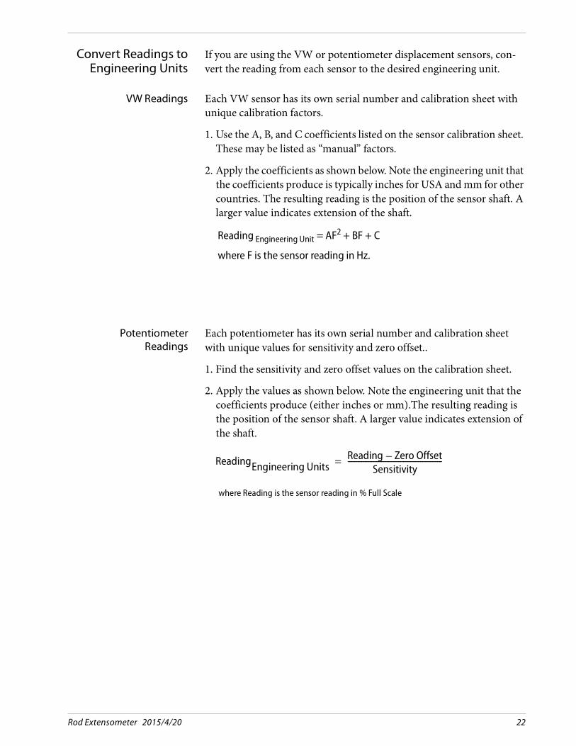
Convert Readings toEngineering Units
If you are using the VW or potentiometer displacement sensors, con-vert the reading from each sensor to the desired engineering unit.
VW Readings Each VW sensor has its own serial number and calibration sheet with unique calibration factors.
1. Use the A, B, and C coefficients listed on the sensor calibration sheet.These may be listed as “manual” factors.
2. Apply the coefficients as shown below. Note the engineering unit thatthe coefficients produce is typically inches for USA and mm for othercountries. The resulting reading is the position of the sensor shaft. Alarger value indicates extension of the shaft.
PotentiometerReadings
Each potentiometer has its own serial number and calibration sheet with unique values for sensitivity and zero offset..
1. Find the sensitivity and zero offset values on the calibration sheet.
2. Apply the values as shown below. Note the engineering unit that thecoefficients produce (either inches or mm).The resulting reading isthe position of the sensor shaft. A larger value indicates extension ofthe shaft.
Reading Engineering Unit = AF2 + BF + C
where F is the sensor reading in Hz.
where Reading is the sensor reading in % Full Scale
ReadingEngineering UnitsReading Zero Offset–
Sensitivity--------------------------------------------------------=
Rod Extensometer 2015/4/20 23
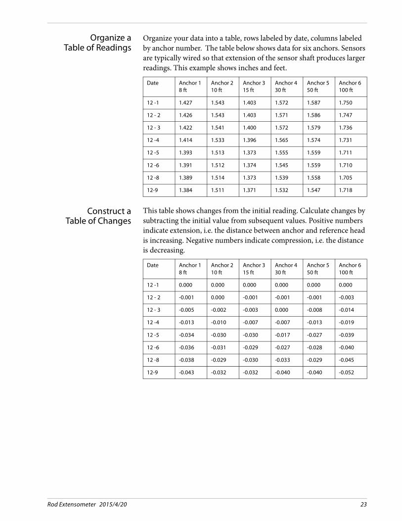
Organize aTable of Readings
Organize your data into a table, rows labeled by date, columns labeled by anchor number. The table below shows data for six anchors. Sensors are typically wired so that extension of the sensor shaft produces larger readings. This example shows inches and feet.
Construct aTable of Changes
This table shows changes from the initial reading. Calculate changes by subtracting the initial value from subsequent values. Positive numbers indicate extension, i.e. the distance between anchor and reference head is increasing. Negative numbers indicate compression, i.e. the distance is decreasing.
Date Anchor 18 ft
Anchor 210 ft
Anchor 315 ft
Anchor 430 ft
Anchor 550 ft
Anchor 6100 ft
12 -1 1.427 1.543 1.403 1.572 1.587 1.750
12 - 2 1.426 1.543 1.403 1.571 1.586 1.747
12 - 3 1.422 1.541 1.400 1.572 1.579 1.736
12 -4 1.414 1.533 1.396 1.565 1.574 1.731
12 -5 1.393 1.513 1.373 1.555 1.559 1.711
12 -6 1.391 1.512 1.374 1.545 1.559 1.710
12 -8 1.389 1.514 1.373 1.539 1.558 1.705
12-9 1.384 1.511 1.371 1.532 1.547 1.718
Date Anchor 18 ft
Anchor 210 ft
Anchor 315 ft
Anchor 430 ft
Anchor 550 ft
Anchor 6100 ft
12 -1 0.000 0.000 0.000 0.000 0.000 0.000
12 - 2 -0.001 0.000 -0.001 -0.001 -0.001 -0.003
12 - 3 -0.005 -0.002 -0.003 0.000 -0.008 -0.014
12 -4 -0.013 -0.010 -0.007 -0.007 -0.013 -0.019
12 -5 -0.034 -0.030 -0.030 -0.017 -0.027 -0.039
12 -6 -0.036 -0.031 -0.029 -0.027 -0.028 -0.040
12 -8 -0.038 -0.029 -0.030 -0.033 -0.029 -0.045
12-9 -0.043 -0.032 -0.032 -0.040 -0.040 -0.052
Rod Extensometer 2015/4/20 24
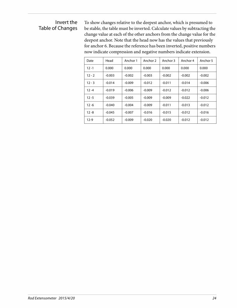
Invert theTable of Changes
To show changes relative to the deepest anchor, which is presumed to be stable, the table must be inverted. Calculate values by subtracting the change value at each of the other anchors from the change value for the deepest anchor. Note that the head now has the values that previously for anchor 6. Because the reference has been inverted, positive numbers now indicate compression and negative numbers indicate extension.
Date Head Anchor 1 Anchor 2 Anchor 3 Anchor 4 Anchor 5
12 -1 0.000 0.000 0.000 0.000 0.000 0.000
12 - 2 -0.003 -0.002 -0.003 -0.002 -0.002 -0.002
12 - 3 -0.014 -0.009 -0.012 -0.011 -0.014 -0.006
12 -4 -0.019 -0.006 -0.009 -0.012 -0.012 -0.006
12 -5 -0.039 -0.005 -0.009 -0.009 -0.022 -0.012
12 -6 -0.040 -0.004 -0.009 -0.011 -0.013 -0.012
12 -8 -0.045 -0.007 -0.016 -0.015 -0.012 -0.016
12-9 -0.052 -0.009 -0.020 -0.020 -0.012 -0.012

Rod Extensometer 2015/4/20 25
Appendix 1: Packer Anchors
General The packer anchor system requires the following components:• Packer anchors.• Grout tubing for each packer anchor.• Grout, water, and mixing tub.• Hand-operated grout pump. We recommend testing the grout pump
with the intended grout mix grout before beginning the installationprocess. The water/cement ratio is not extremely important, butcheck that it can be pumped. Start with a ratio of 1:2 (water tocement) and modify as needed.
Assembly 1. Lay out components of extensometer: packer anchors, rods and pro-tective tubing, and grout tubing.
2. Adjust rod lengths according to instructions in the first part of thismanual.
3. Cut grout tubing long enough for easy connection to a grout pumplater.
4. Attach grout tubing to packer anchors. Note that tubing from deeperpacker anchors must pass through the shallower packer anchors.
5. Attach packer anchors to rods.
6. Assemble rods and protective pipe. Note that rods from deeperanchors must pass through the shallower anchors.
Optional: Use the grout pump to pump water through the tubing until it exits the packer anchor. Use this test to check the volume of water (or grout) required for the tubing. Add this to the volume of grout required for the packer.
Installation 1. Follow steps listed previously. Since packer anchors will be used, do not grout the borehole.
2. To activate the anchors, follow instructions on the next page.

Rod Extensometer 2015/4/20 26
Activation 1. Connect grout tubing to grout pump.
2. Pump clean water through the tubing. This important stepprevents premature setup of the grout.
3. Pump the grout until it is hard to pump. After 1 to 2 minutes, trypumping some more to replace any grout that has leaked from thepacker.
4. Pinch and fold the grout tubing to keep pressure in the packer. Tiethe fold.
5. Disconnect tubing from the pump. Watch out for splashing.
6. Wash out the pump immediately.
7. Activate other anchors following the same steps.

Rod Extensometer 2015/4/20 27
Appendix 2: Hydraulic Anchors
Introduction Hydraulic anchors are typically supplied with hydraulic tubing that is cut to the specified length and pre-filled with oil. A hand-operated hydraulic pump is used to activate the anchors.
Assembly 1. Lay out components of extensometer: hydraulic anchors, rods and protective pipe, grout tubing, and hydraulic tubing.
2. Adjust rod lengths and assemble the extensometer according toinstructions provided in the first part of this manual. The hydraulictubing cannot be recovered, so tape it to the rods for easier installa-tion.
Installation 1. Follow steps discussed previously in this manual.
2. To activate the anchors, follow instructions on the next page.
Activation 1. Connect hydraulic tubing from one anchor to the hydraulic pump.. Use the couplings and ferrules provided.
2. Fill the graduated reservoir on the pump with oil.
3. Start pumping. Pressure will build to between 800 and 1300 psibefore the prongs in the anchor begin to extend and then will drop to500 to 600 psi.
4. The level of oil in the hydraulic reservoir will drop as the prongs con-tinue to extend. The graphs on the next page show the relationbetween extension of the prongs and level of oil in the reservoir.
5. When the anchor has been activated, disconnect the tubing from thepump and tie it off.

Rod Extensometer 2015/4/20 28
Double-ActingAnchor
The graph below shows extension of the three anchor prongs in terms of a diameter of a circle. Note that both the anchor diameter and the reservoir level are in inches.
Single-Acting Anchor The graph below shows extension of the three anchor prongs in terms of a diameter of a circle. Note that both the anchor diameter and the reservoir level are in inches.
Single Acting Anchor
Recommended