Diaphragm Motor-Driven Metering PumpSigma/ 1 Control Type S1Cb
Operating instructions
Original operating instructions (2006/42/EC)Part no. 985450 BA SI 061 01/14 EN
Please carefully read these operating instructions before use! · Do not discard!The operator shall be liable for any damage caused by installation or operating errors!
Technical changes reserved.
Read the following supplementary information in its entirety! Should youalready know this information, you will benefit more from referring to theoperating instructions.
The following are highlighted separately in the document:
n Enumerated lists
Handling instructions
ð Outcome of the operation guidelines
- see (reference)
Information
This provides important information relating to the correctoperation of the device or is intended to make your workeasier.
Safety notes
Safety notes are identified by pictograms - see Safety Chapter.
At the time of going to press, these operating instructions conformed to thecurrent EU regulations.
Please state identity code and serial number, which you can find on thenameplate when you contact us or order spare parts. This enables thedevice type and material versions to be clearly identified.
Supplementary information
Fig. 1: Please read!
Validity
State the identity code and serial number
Supplemental instructions
2
Table of contents1 Identity code.................................................................................... 5
2 Safety chapter................................................................................. 8
3 Storage, transport and unpacking................................................. 12
4 Overview of equipment and control elements............................... 134.1 Key functions......................................................................... 154.2 LCD screen identifiers........................................................... 15
5 Functional description.................................................................... 185.1 Pump..................................................................................... 185.2 Liquid end.............................................................................. 195.3 Bleed valve and integrated relief valve ................................ 195.4 Multi-layer safety diaphragm................................................. 205.5 Operating modes................................................................... 205.6 Functions............................................................................... 215.7 Options.................................................................................. 225.8 Function and fault indicator................................................... 225.9 LCD screen........................................................................... 235.10 LED displays....................................................................... 235.11 Hierarchy of operating modes, functions and fault sta‐
tuses.................................................................................... 23
6 Assembly....................................................................................... 24
7 Installation..................................................................................... 267.1 Installation, hydraulic............................................................. 267.1.1 Basic installation notes....................................................... 307.2 Installation, electrical............................................................. 317.2.1 Control connectors............................................................. 327.2.2 HMI operating unit.............................................................. 397.2.3 Pump, power supply........................................................... 407.2.4 Other units.......................................................................... 41
8 Set up............................................................................................ 428.1 Basic principles of control adjustment................................... 428.2 Checking adjustable values / error messages...................... 428.3 Changing to adjustment mode.............................................. 438.4 Selecting the operating mode (Menu "Mode")...................... 448.5 Operating mode settings (menu "Settings").......................... 448.5.1 "Manual" operating mode settings..................................... 458.5.2 "Batch" mode settings ....................................................... 458.5.3 "Contact" operating mode settings..................................... 468.5.4 "Analog" operating mode settings...................................... 498.6 Programmable function settings ("Settings" menu ).............. 528.6.1 Settings for the “Auxiliary frequency” function (AUX
menu)................................................................................. 528.6.2 Settings for the “Calibrate” function (CALIBRATE menu). . 538.6.3 Settings for the “Metering” function (DOSING menu)........ 548.6.4 Settings for the “Dosing monitor” function (DOSING
MONITOR menu)............................................................... 558.6.5 Settings for the “Relay” function (RELAY menu)................ 558.6.6 Settings for the “Analog output” function (ANALOG
OUTPUT menu)................................................................. 578.6.7 Settings for the “Diaphragm break” function (DIA‐
PHRAGM BREAK menu)................................................... 578.6.8 Settings in the "System" menu" (SYSTEM menu)............. 588.7 Service (SERVICE menu)..................................................... 588.7.1 Clear counters (CLEAR COUNTERS menu)..................... 588.7.2 Adjusting the Display (DISPLAY menu)............................. 59
Table of contents
3
8.7.3 HMI logout.......................................................................... 598.7.4 Security (SECURITY menu)............................................... 608.8 Information about the pump (INFORMATION menu)............ 618.9 Set language (LANGUAGE menu)........................................ 61
9 Start up.......................................................................................... 62
10 Operation....................................................................................... 6410.1 Manual................................................................................ 6410.2 Remote operation................................................................ 66
11 Maintenance.................................................................................. 67
12 Repairs.......................................................................................... 6912.1 Cleaning valves................................................................... 6912.2 Replacing the diaphragm.................................................... 71
13 Troubleshooting............................................................................. 7513.1 Faults without a fault alert................................................... 7513.2 Fault alerts.......................................................................... 7613.3 Warning messages............................................................. 7713.4 All other faults..................................................................... 78
14 Decommissioning.......................................................................... 79
15 Technical data............................................................................... 8115.1 Performance data................................................................ 8115.2 Viscosity.............................................................................. 8215.3 Shipping weight................................................................... 8215.4 Wetted materials................................................................. 8215.5 Ambient conditions.............................................................. 8215.5.1 Ambient temperatures...................................................... 8215.5.2 Media temperatures......................................................... 8315.5.3 Air humidity...................................................................... 8315.5.4 Enclosure rating and safety requirements........................ 8315.6 Electrical connection........................................................... 8315.7 Diaphragm rupture sensor.................................................. 8415.8 Relay................................................................................... 8415.9 Sound pressure level.......................................................... 85
16 Dimensional drawings................................................................... 86
17 Motor data sheets.......................................................................... 89
18 Exploded view drawings................................................................ 9018.1 Exploded drawings Sigma/ 1............................................... 90
19 Wearing parts for S1Cb................................................................. 9619.1 Standard.............................................................................. 9619.2 Physiological safety............................................................. 97
20 Diagrams for adjusting the capacity.............................................. 99
21 EC Declaration of Conformity for Machinery............................... 100
22 Operating / adjustment overview................................................. 101
23 Continuous displays.................................................................... 102
24 Index............................................................................................ 104
Table of contents
4
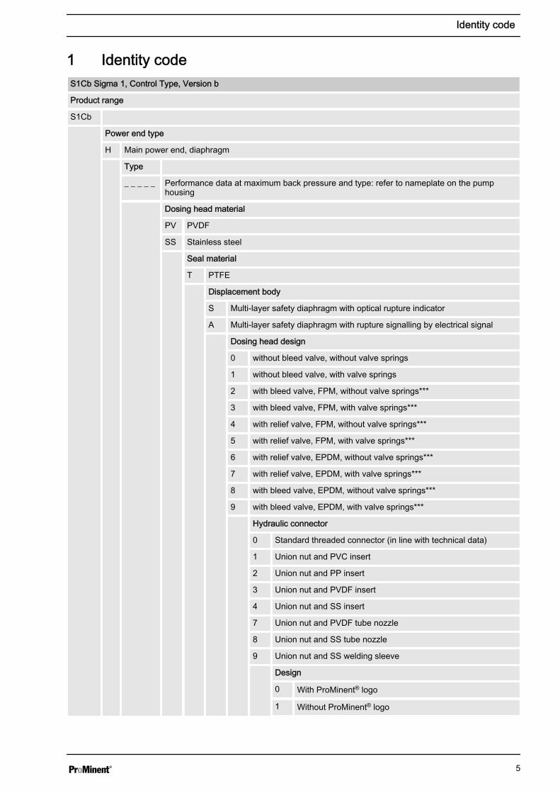
1 Identity codeS1Cb Sigma 1, Control Type, Version b
Product range
S1Cb
Power end type
H Main power end, diaphragm
Type
_ _ _ _ _ Performance data at maximum back pressure and type: refer to nameplate on the pumphousing
Dosing head material
PV PVDF
SS Stainless steel
Seal material
T PTFE
Displacement body
S Multi-layer safety diaphragm with optical rupture indicator
A Multi-layer safety diaphragm with rupture signalling by electrical signal
Dosing head design
0 without bleed valve, without valve springs
1 without bleed valve, with valve springs
2 with bleed valve, FPM, without valve springs***
3 with bleed valve, FPM, with valve springs***
4 with relief valve, FPM, without valve springs***
5 with relief valve, FPM, with valve springs***
6 with relief valve, EPDM, without valve springs***
7 with relief valve, EPDM, with valve springs***
8 with bleed valve, EPDM, without valve springs***
9 with bleed valve, EPDM, with valve springs***
Hydraulic connector
0 Standard threaded connector (in line with technical data)
1 Union nut and PVC insert
2 Union nut and PP insert
3 Union nut and PVDF insert
4 Union nut and SS insert
7 Union nut and PVDF tube nozzle
8 Union nut and SS tube nozzle
9 Union nut and SS welding sleeve
Design
0 With ProMinent® logo
1 Without ProMinent® logo
Identity code
5
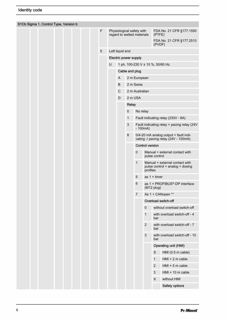
S1Cb Sigma 1, Control Type, Version b
F Physiological safety withregard to wetted materials
FDA No. 21 CFR §177.1550(PTFE)
FDA No. 21 CFR §177.2510(PVDF)
5 Left liquid end
Electric power supply
U 1 ph, 100-230 V ± 10 %, 50/60 Hz
Cable and plug
A 2 m European
B 2 m Swiss
C 2 m Australian
D 2 m USA
Relay
0 No relay
1 Fault indicating relay (230V - 8A)
3 Fault indicating relay + pacing relay (24V- 100mA)
8 0/4-20 mA analog output + fault indi‐cating -/ pacing relay (24V - 100mA)
Control version
0 Manual + external contact withpulse control
1 Manual + external contact withpulse control + analog + dosingprofiles
5 as 1 + timer
6 as 1 + PROFIBUS®-DP interface(M12 plug)
7 As 1 + CANopen **
Overload switch-off
0 without overload switch-off
1 with overload switch-off - 4bar
2 with overload switch-off - 7bar
3 with overload switch-off - 10bar
Operating unit (HMI)
S HMI (0.5 m cable)
1 HMI + 2 m cable
2 HMI + 5 m cable
3 HMI + 10 m cable
X without HMI
Safety options
Identity code
6
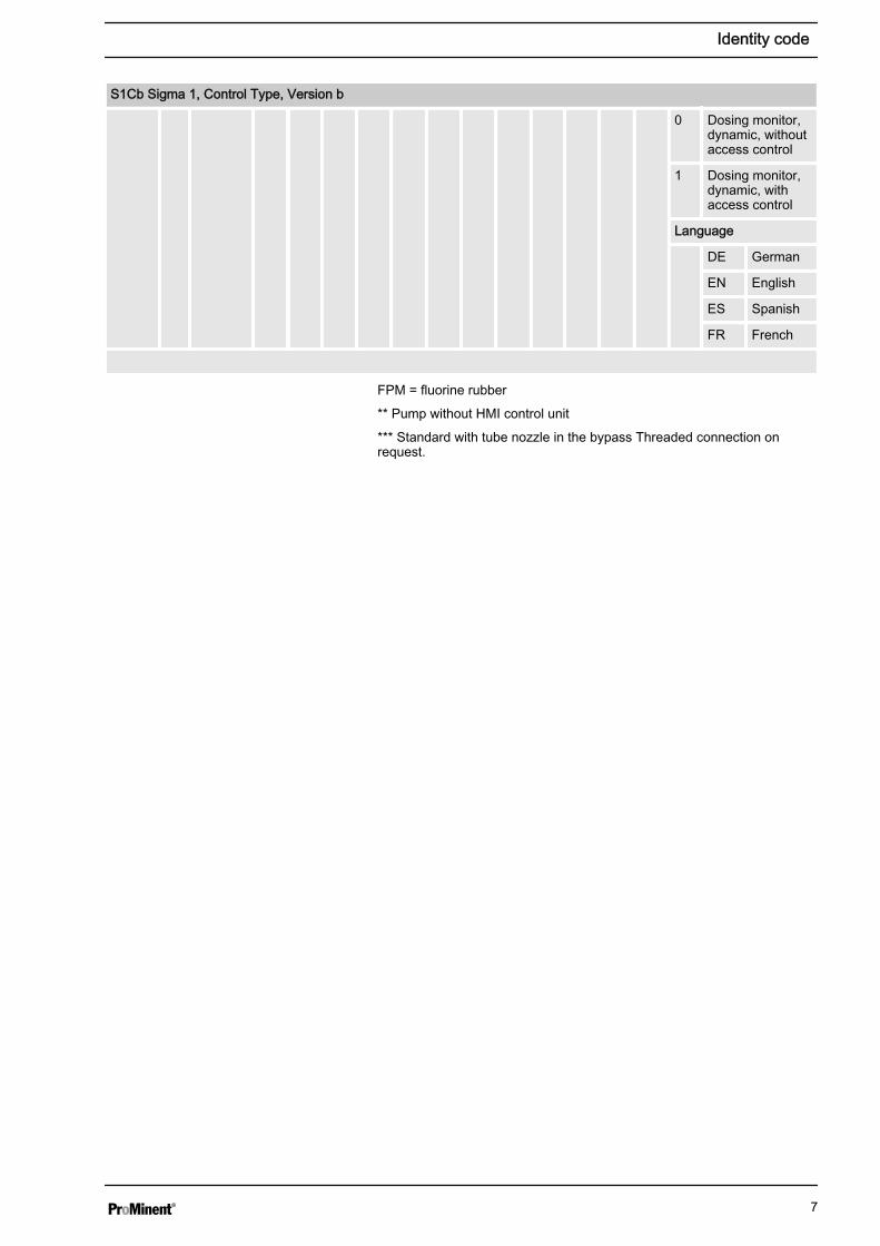
S1Cb Sigma 1, Control Type, Version b
0 Dosing monitor,dynamic, withoutaccess control
1 Dosing monitor,dynamic, withaccess control
Language
DE German
EN English
ES Spanish
FR French
FPM = fluorine rubber
** Pump without HMI control unit
*** Standard with tube nozzle in the bypass Threaded connection onrequest.
Identity code
7
2 Safety chapter
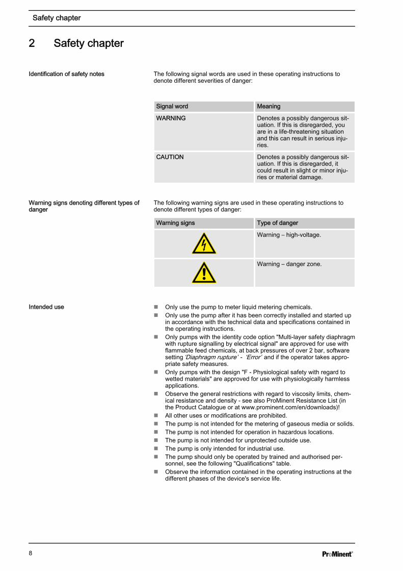
The following signal words are used in these operating instructions todenote different severities of danger:
Signal word Meaning
WARNING Denotes a possibly dangerous sit‐uation. If this is disregarded, youare in a life-threatening situationand this can result in serious inju‐ries.
CAUTION Denotes a possibly dangerous sit‐uation. If this is disregarded, itcould result in slight or minor inju‐ries or material damage.
The following warning signs are used in these operating instructions todenote different types of danger:
Warning signs Type of danger
Warning – high-voltage.
Warning – danger zone.
n Only use the pump to meter liquid metering chemicals.n Only use the pump after it has been correctly installed and started up
in accordance with the technical data and specifications contained inthe operating instructions.
n Only pumps with the identity code option "Multi-layer safety diaphragmwith rupture signalling by electrical signal" are approved for use withflammable feed chemicals, at back pressures of over 2 bar, softwaresetting ‘Diaphragm rupture’ - ‘Error’ and if the operator takes appro‐priate safety measures.
n Only pumps with the design "F - Physiological safety with regard towetted materials" are approved for use with physiologically harmlessapplications.
n Observe the general restrictions with regard to viscosity limits, chem‐ical resistance and density - see also ProMinent Resistance List (inthe Product Catalogue or at www.prominent.com/en/downloads)!
n All other uses or modifications are prohibited.n The pump is not intended for the metering of gaseous media or solids.n The pump is not intended for operation in hazardous locations.n The pump is not intended for unprotected outside use.n The pump is only intended for industrial use.n The pump should only be operated by trained and authorised per‐
sonnel, see the following "Qualifications" table.n Observe the information contained in the operating instructions at the
different phases of the device's service life.
Identification of safety notes
Warning signs denoting different types ofdanger
Intended use
Safety chapter
8
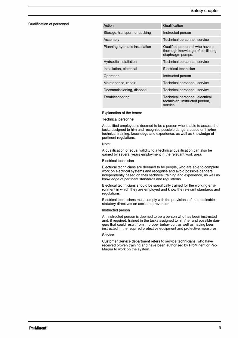
Action Qualification
Storage, transport, unpacking Instructed person
Assembly Technical personnel, service
Planning hydraulic installation Qualified personnel who have athorough knowledge of oscillatingdiaphragm pumps.
Hydraulic installation Technical personnel, service
Installation, electrical Electrical technician
Operation Instructed person
Maintenance, repair Technical personnel, service
Decommissioning, disposal Technical personnel, service
Troubleshooting Technical personnel, electricaltechnician, instructed person,service
Explanation of the terms:
Technical personnel
A qualified employee is deemed to be a person who is able to assess thetasks assigned to him and recognise possible dangers based on his/hertechnical training, knowledge and experience, as well as knowledge ofpertinent regulations.
Note:
A qualification of equal validity to a technical qualification can also begained by several years employment in the relevant work area.
Electrical technician
Electrical technicians are deemed to be people, who are able to completework on electrical systems and recognise and avoid possible dangersindependently based on their technical training and experience, as well asknowledge of pertinent standards and regulations.
Electrical technicians should be specifically trained for the working envi‐ronment in which they are employed and know the relevant standards andregulations.
Electrical technicians must comply with the provisions of the applicablestatutory directives on accident prevention.
Instructed person
An instructed person is deemed to be a person who has been instructedand, if required, trained in the tasks assigned to him/her and possible dan‐gers that could result from improper behaviour, as well as having beeninstructed in the required protective equipment and protective measures.
Service
Customer Service department refers to service technicians, who havereceived proven training and have been authorised by ProMinent or Pro‐Maqua to work on the system.
Qualification of personnel
Safety chapter
9
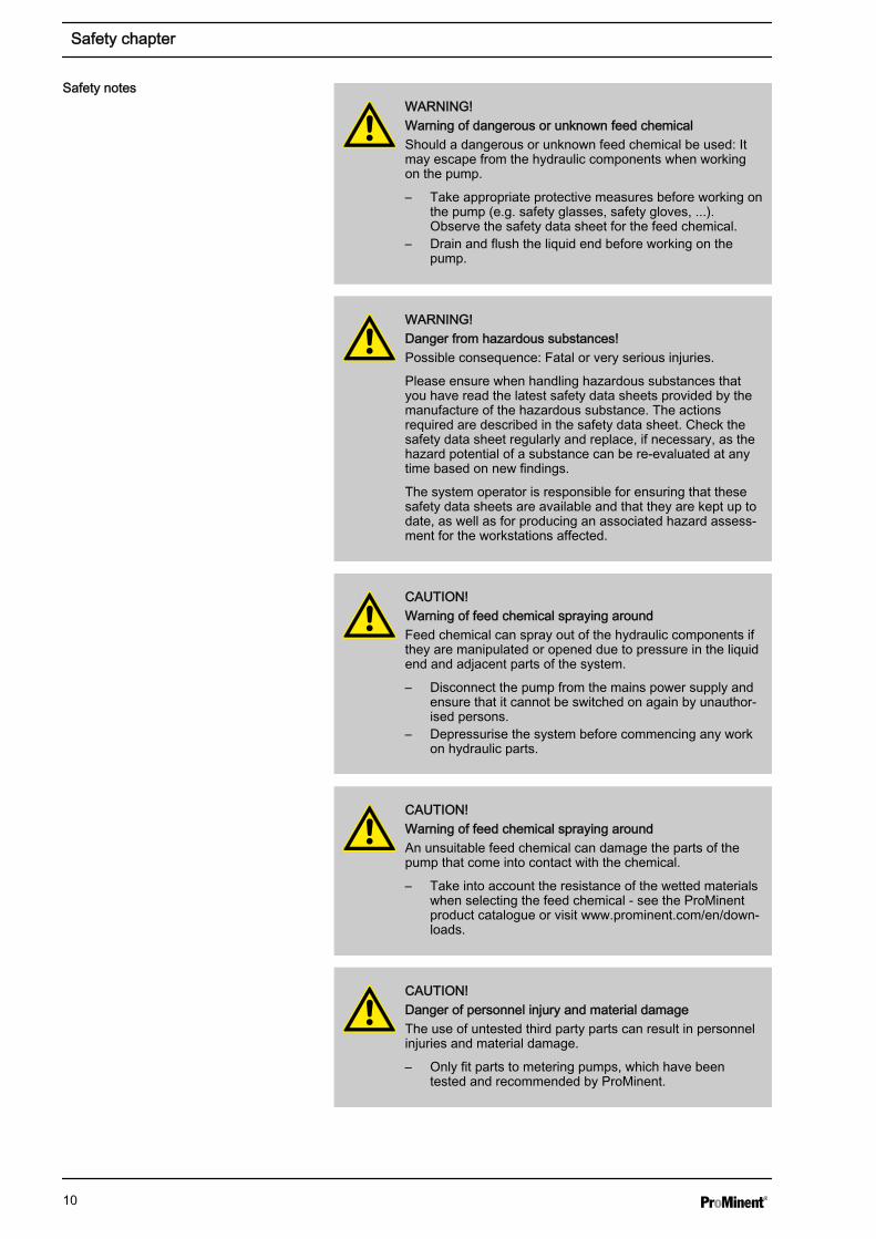
WARNING!Warning of dangerous or unknown feed chemicalShould a dangerous or unknown feed chemical be used: Itmay escape from the hydraulic components when workingon the pump.
– Take appropriate protective measures before working onthe pump (e.g. safety glasses, safety gloves, ...).Observe the safety data sheet for the feed chemical.
– Drain and flush the liquid end before working on thepump.
WARNING!Danger from hazardous substances!Possible consequence: Fatal or very serious injuries.
Please ensure when handling hazardous substances thatyou have read the latest safety data sheets provided by themanufacture of the hazardous substance. The actionsrequired are described in the safety data sheet. Check thesafety data sheet regularly and replace, if necessary, as thehazard potential of a substance can be re-evaluated at anytime based on new findings.
The system operator is responsible for ensuring that thesesafety data sheets are available and that they are kept up todate, as well as for producing an associated hazard assess‐ment for the workstations affected.
CAUTION!Warning of feed chemical spraying aroundFeed chemical can spray out of the hydraulic components ifthey are manipulated or opened due to pressure in the liquidend and adjacent parts of the system.
– Disconnect the pump from the mains power supply andensure that it cannot be switched on again by unauthor‐ised persons.
– Depressurise the system before commencing any workon hydraulic parts.
CAUTION!Warning of feed chemical spraying aroundAn unsuitable feed chemical can damage the parts of thepump that come into contact with the chemical.
– Take into account the resistance of the wetted materialswhen selecting the feed chemical - see the ProMinentproduct catalogue or visit www.prominent.com/en/down‐loads.
CAUTION!Danger of personnel injury and material damageThe use of untested third party parts can result in personnelinjuries and material damage.
– Only fit parts to metering pumps, which have beentested and recommended by ProMinent.
Safety notes
Safety chapter
10
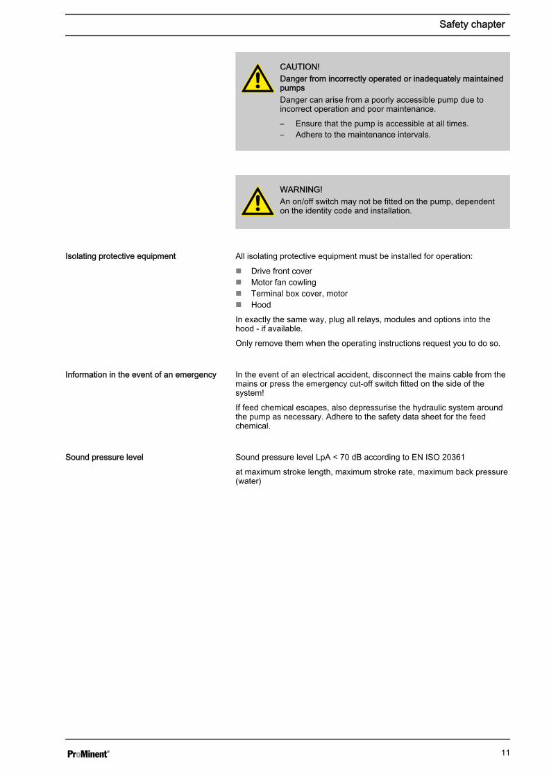
CAUTION!Danger from incorrectly operated or inadequately maintainedpumpsDanger can arise from a poorly accessible pump due toincorrect operation and poor maintenance.
– Ensure that the pump is accessible at all times.– Adhere to the maintenance intervals.
WARNING!An on/off switch may not be fitted on the pump, dependenton the identity code and installation.
All isolating protective equipment must be installed for operation:
n Drive front covern Motor fan cowlingn Terminal box cover, motorn Hood
In exactly the same way, plug all relays, modules and options into thehood - if available.
Only remove them when the operating instructions request you to do so.
In the event of an electrical accident, disconnect the mains cable from themains or press the emergency cut-off switch fitted on the side of thesystem!
If feed chemical escapes, also depressurise the hydraulic system aroundthe pump as necessary. Adhere to the safety data sheet for the feedchemical.
Sound pressure level LpA < 70 dB according to EN ISO 20361
at maximum stroke length, maximum stroke rate, maximum back pressure(water)
Isolating protective equipment
Information in the event of an emergency
Sound pressure level
Safety chapter
11

3 Storage, transport and unpacking
WARNING!Only return the metering pump for repair in a cleaned stateand with a flushed liquid end - refer to the chapter "Decom‐missioning"!
Only return metering pumps with a completed Decontamina‐tion Declaration form. The Decontamination Declaration con‐stitutes an integral part of an inspection / repair order. A unitcan only be inspected or repaired when a Declaration ofDecontamination Form is submitted that has been completedcorrectly and in full by an authorised and qualified person onbehalf of the pump operator.
The "Decontamination Declaration Form" can be found atwww.prominent.com/en/downloads.
CAUTION!Danger of material damageThe device can be damaged by incorrect or improper storageor transportation!
– The unit should only be stored or transported in a wellpackaged state - preferably in its original packaging.
– The packaged unit should also only be stored or trans‐ported in accordance with the stipulated storage condi‐tions.
– The packaged unit should be protected from moistureand the ingress of chemicals.
Compare the delivery note with the scope of supply:
Personnel: n Technical personnel
1. Plug the caps on the valves.
3. Preferably place the pump standing vertically on a pallet and secureagainst falling over.
4. Cover the pump with a tarpaulin cover - allowing rear ventilation.
Store the pump in a dry, sealed place under the ambient conditionsaccording to chapter "Technical Data".
Safety notes
Scope of supply
Storage
Storage, transport and unpacking
12
4 Overview of equipment and control elements
P_SI_0126_SW
1
2
5
6
7
4
3
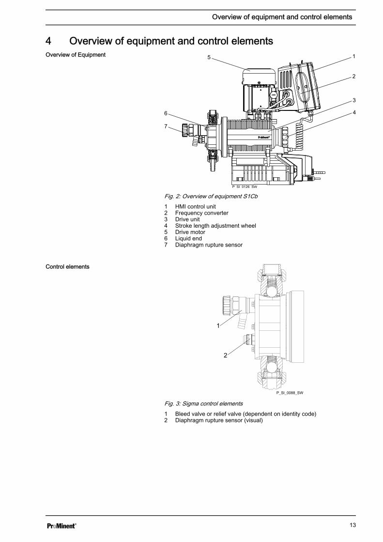
Fig. 2: Overview of equipment S1Cb1 HMI control unit2 Frequency converter3 Drive unit4 Stroke length adjustment wheel5 Drive motor6 Liquid end7 Diaphragm rupture sensor
1
2
P_SI_0088_SW
Fig. 3: Sigma control elements1 Bleed valve or relief valve (dependent on identity code)2 Diaphragm rupture sensor (visual)
Overview of Equipment
Control elements
Overview of equipment and control elements
13
2
1
5 10
8
96
7
3
4
P_SI_0105_SW
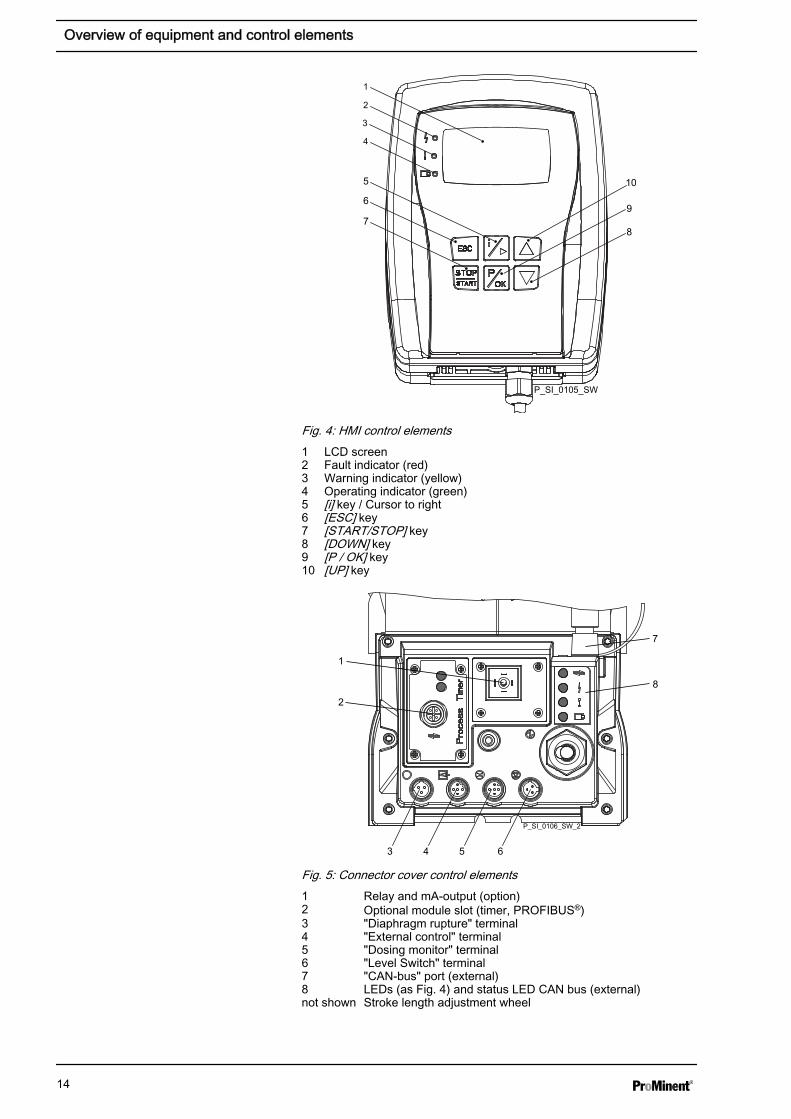
Fig. 4: HMI control elements1 LCD screen2 Fault indicator (red)3 Warning indicator (yellow)4 Operating indicator (green)5 [i] key / Cursor to right6 [ESC] key7 [START/STOP] key8 [DOWN] key9 [P / OK] key10 [UP] key
P_SI_0106_SW_2
6
7
543
2
1
8
Fig. 5: Connector cover control elements1 Relay and mA-output (option)2 Optional module slot (timer, PROFIBUS®)3 "Diaphragm rupture" terminal4 "External control" terminal5 "Dosing monitor" terminal6 "Level Switch" terminal7 "CAN-bus" port (external)8 LEDs (as Fig. 4) and status LED CAN bus (external)not shown Stroke length adjustment wheel
Overview of equipment and control elements
14
4.1 Key functionsKey Application In continuous displays (operation) In adjustment mode (set up)
[STOP/START] Pressed briefly Stop pump, Stop pump,
start pump start pump
[P / OK] Pressed briefly Start batch (only in ‘Batch’ oper‐ating mode),
Acknowledge errors
Confirm entry - jump to next menuoption or to continuous display
Pressed for 2 s Change to adjustment mode -
[ i / >] 1x short press Change between the continuousdisplays
Change between the secondarydisplays
Change between "Changing indi‐vidual numbers" and "Changing anumber"
Change to the next digit
1x long press Change from the continuous dis‐plays to the secondary displays
[UP], [DOWN] Pressed briefly Change directly changeable varia‐bles
Select another setting, changeindividual number or number.
Simultaneous longpress
Priming -
[ESC] Pressed briefly - Jumps back one menu level
Pressed for 2s - Jumps to a continuous display
Exit the setting menu withoutsaving
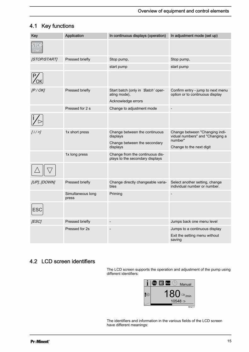
4.2 LCD screen identifiersThe LCD screen supports the operation and adjustment of the pump usingdifferent identifiers:
10548
Manual
180 /min
Stop Aux
B0412
The identifiers and information in the various fields of the LCD screenhave different meanings:
Overview of equipment and control elements
15
1 2 3 4 5
69
10
78
B0413
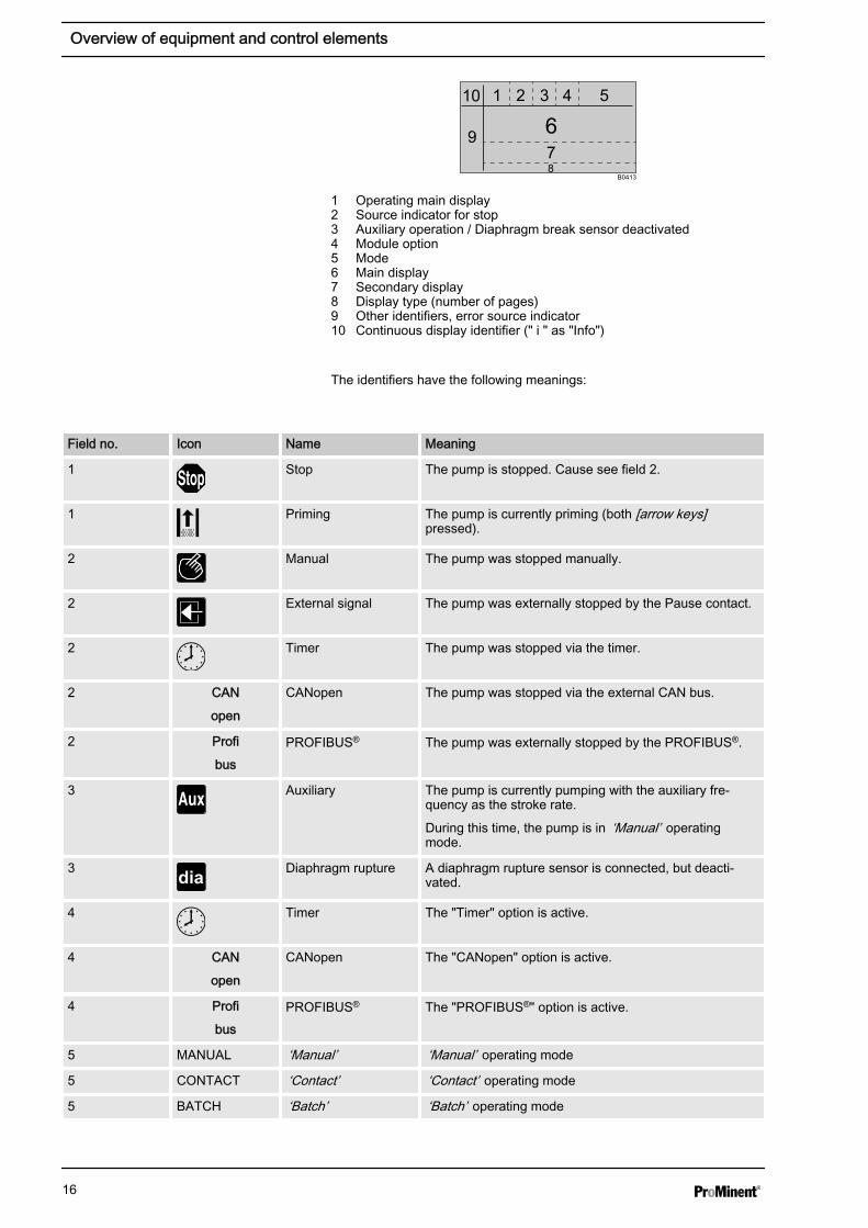
1 Operating main display2 Source indicator for stop3 Auxiliary operation / Diaphragm break sensor deactivated4 Module option5 Mode6 Main display7 Secondary display8 Display type (number of pages)9 Other identifiers, error source indicator10 Continuous display identifier (" i " as "Info")
The identifiers have the following meanings:
Field no. Icon Name Meaning
1 Stop The pump is stopped. Cause see field 2.
1 Priming The pump is currently priming (both [arrow keys]pressed).
2 Manual The pump was stopped manually.
2 External signal The pump was externally stopped by the Pause contact.
2 Timer The pump was stopped via the timer.
2 CAN
open
CANopen The pump was stopped via the external CAN bus.
2 Profi
busPROFIBUS® The pump was externally stopped by the PROFIBUS®.
3 Auxiliary The pump is currently pumping with the auxiliary fre‐quency as the stroke rate.
During this time, the pump is in ‘Manual’ operatingmode.
3 Diaphragm rupture A diaphragm rupture sensor is connected, but deacti‐vated.
4 Timer The "Timer" option is active.
4 CAN
open
CANopen The "CANopen" option is active.
4 Profi
busPROFIBUS® The "PROFIBUS®" option is active.
5 MANUAL ‘Manual’ ‘Manual’ operating mode
5 CONTACT ‘Contact’ ‘Contact’ operating mode
5 BATCH ‘Batch’ ‘Batch’ operating mode
Overview of equipment and control elements
16
Field no. Icon Name Meaning
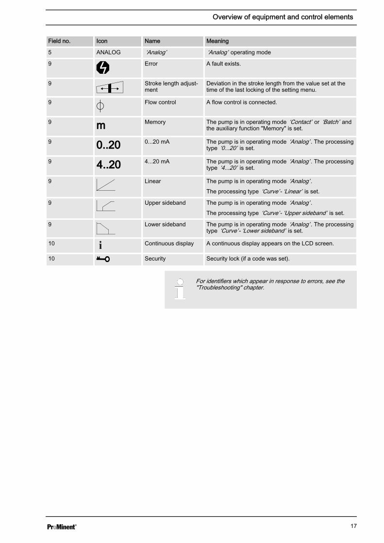
5 ANALOG ‘Analog’ ‘Analog’ operating mode
9 Error A fault exists.
9 Stroke length adjust‐ment
Deviation in the stroke length from the value set at thetime of the last locking of the setting menu.
9 Flow control A flow control is connected.
9 mm Memory The pump is in operating mode ‘Contact’ or ‘Batch’ andthe auxiliary function "Memory" is set.
9 0..200..20 0...20 mA The pump is in operating mode ‘Analog’ . The processingtype ‘0...20’ is set.
9 4..204..20 4...20 mA The pump is in operating mode ‘Analog’ . The processingtype ‘4...20’ is set.
9 Linear The pump is in operating mode ‘Analog’ .The processing type ‘Curve’ - ‘Linear’ is set.
9 Upper sideband The pump is in operating mode ‘Analog’ .The processing type ‘Curve’ - ‘Upper sideband’ is set.
9 Lower sideband The pump is in operating mode ‘Analog’ . The processingtype ‘Curve’ - ‘Lower sideband’ is set.
10 Continuous display A continuous display appears on the LCD screen.
10 Security Security lock (if a code was set).
For identifiers which appear in response to errors, see the"Troubleshooting" chapter.
Overview of equipment and control elements
17
5 Functional description5.1 Pump
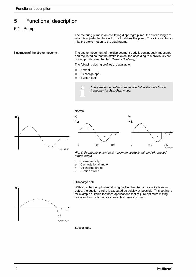
The metering pump is an oscillating diaphragm pump, the stroke length ofwhich is adjustable. An electric motor drives the pump. The slide rod trans‐mits the stoke motion to the diaphragms.
The stroke movement of the displacement body is continuously measuredand regulated so that the stroke is executed according to a previously setdosing profile, see chapter ‘Set-up’ - ‘Metering’ .The following dosing profiles are available:
n Normaln Discharge opti.n Suction opti.
Every metering profile is ineffective below the switch-overfrequency for Start/Stop mode.
Normal
0
s s
a)
180 360 0
b)
180 360
ω ω
P_PL_0009_SW
Fig. 6: Stroke movement at a) maximum stroke length and b) reducedstroke length.t Stroke velocity Cam rotational angle+ Discharge stroke- Suction stroke
Discharge opti.
With a discharge optimised dosing profile, the discharge stroke is elon‐gated, the suction stroke is executed as quickly as possible. This setting isfor example suitable for those applications that require optimum mixingratios and as continuous as possible chemical mixing.
Suction opti.
Illustration of the stroke movement
P_SI_0120_SW
s
t
P_SI_0103_SW
s
t
Functional description
18
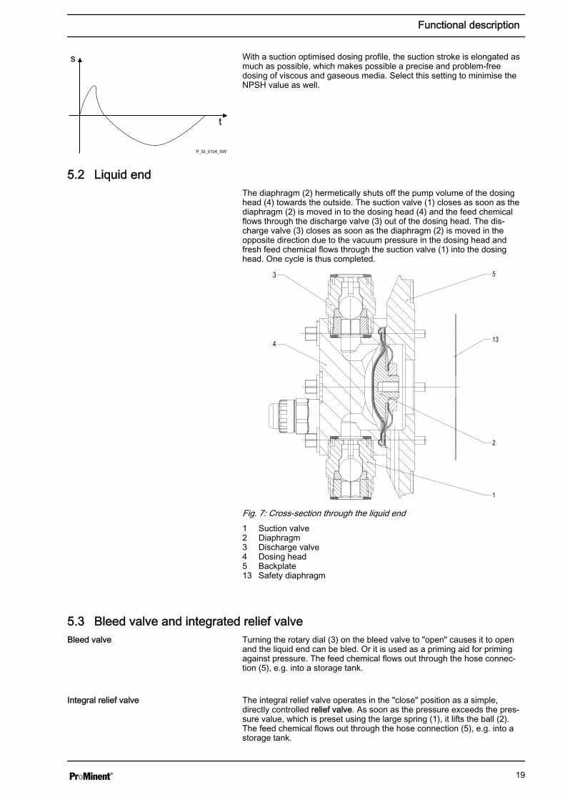
With a suction optimised dosing profile, the suction stroke is elongated asmuch as possible, which makes possible a precise and problem-freedosing of viscous and gaseous media. Select this setting to minimise theNPSH value as well.
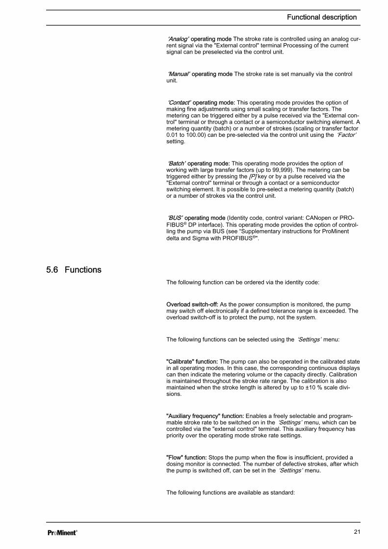
5.2 Liquid endThe diaphragm (2) hermetically shuts off the pump volume of the dosinghead (4) towards the outside. The suction valve (1) closes as soon as thediaphragm (2) is moved in to the dosing head (4) and the feed chemicalflows through the discharge valve (3) out of the dosing head. The dis‐charge valve (3) closes as soon as the diaphragm (2) is moved in theopposite direction due to the vacuum pressure in the dosing head andfresh feed chemical flows through the suction valve (1) into the dosinghead. One cycle is thus completed.
4
2
1
53
13
Fig. 7: Cross-section through the liquid end1 Suction valve2 Diaphragm3 Discharge valve4 Dosing head5 Backplate13 Safety diaphragm
5.3 Bleed valve and integrated relief valve Turning the rotary dial (3) on the bleed valve to "open" causes it to openand the liquid end can be bled. Or it is used as a priming aid for primingagainst pressure. The feed chemical flows out through the hose connec‐tion (5), e.g. into a storage tank.
The integral relief valve operates in the "close" position as a simple,directly controlled relief valve. As soon as the pressure exceeds the pres‐sure value, which is preset using the large spring (1), it lifts the ball (2).The feed chemical flows out through the hose connection (5), e.g. into astorage tank.
P_SI_0104_SW
s
t
Bleed valve
Integral relief valve
Functional description
19

The integral relief valve can only protect the motor and the gear, and thenonly against impermissible positive pressure that is caused by themetering pump itself. It cannot protect the system against positive pres‐sure.
The integral relief valve works as a bleed valve as soon as the rotary dial(3) is turned to "open": The valve opens and the liquid end can be bled. Orit is used as a priming aid for priming against pressure.
1 2
5
3
P_SI_0109
Fig. 8: Relief valve and integrated relief valve1 Spring, large2 Ball3 Rotary dial5 Hose connection
5.4 Multi-layer safety diaphragmWith the visual diaphragm rupture sensor, the lowered red cylinder (6)springs forward beneath the transparent cover (7) so that it then becomesclearly visible Fig. 9.
With the electrical diaphragm rupture sensor, a switch is switched. A con‐nected signalling device must signal the diaphragm rupture.
Fig. 9: Visual diaphragm rupture sensor, triggered and untriggered
The electrical diaphragm rupture sensor is connected to the "diaphragmrupture indicator" terminal. If a diaphragm ruptures, the red LED "Fault"display lights up on the pump and the identifier "Error" and ‘dia’ flash onthe LCD screen.
5.5 Operating modesThe operating modes are selected via the ‘Mode’ menu (dependent onthe identity code, some operating modes may not be present):
Functional description
20
‘Analog’ operating mode The stroke rate is controlled using an analog cur‐rent signal via the "External control" terminal Processing of the currentsignal can be preselected via the control unit.
‘Manual’ operating mode The stroke rate is set manually via the controlunit.
‘Contact’ operating mode: This operating mode provides the option ofmaking fine adjustments using small scaling or transfer factors. Themetering can be triggered either by a pulse received via the "External con‐trol" terminal or through a contact or a semiconductor switching element. Ametering quantity (batch) or a number of strokes (scaling or transfer factor0.01 to 100.00) can be pre-selected via the control unit using the ‘Factor’setting.
‘Batch’ operating mode: This operating mode provides the option ofworking with large transfer factors (up to 99,999). The metering can betriggered either by pressing the [P] key or by a pulse received via the"External control" terminal or through a contact or a semiconductorswitching element. It is possible to pre-select a metering quantity (batch)or a number of strokes via the control unit.
‘BUS’ operating mode (Identity code, control variant: CANopen or PRO‐FIBUS® DP interface). This operating mode provides the option of control‐ling the pump via BUS (see “Supplementary instructions for ProMinentdelta and Sigma with PROFIBUS®".
5.6 FunctionsThe following function can be ordered via the identity code:
Overload switch-off: As the power consumption is monitored, the pumpmay switch off electronically if a defined tolerance range is exceeded. Theoverload switch-off is to protect the pump, not the system.
The following functions can be selected using the ‘Settings’ menu:
"Calibrate" function: The pump can also be operated in the calibrated statein all operating modes. In this case, the corresponding continuous displayscan then indicate the metering volume or the capacity directly. Calibrationis maintained throughout the stroke rate range. The calibration is alsomaintained when the stroke length is altered by up to ±10 % scale divi‐sions.
"Auxiliary frequency" function: Enables a freely selectable and program‐mable stroke rate to be switched on in the ‘Settings’ menu, which can becontrolled via the "external control" terminal. This auxiliary frequency haspriority over the operating mode stroke rate settings.
"Flow" function: Stops the pump when the flow is insufficient, provided adosing monitor is connected. The number of defective strokes, after whichthe pump is switched off, can be set in the ‘Settings’ menu.
The following functions are available as standard:
Functional description
21
"Level switch" function: Information about the liquid/powder level in thechemical feed container is reported to the pump control. To do so, a two-stage level switch must be fitted; it is connected to the "Level switch" ter‐minal.
"Pause" function: The pump can be remotely stopped via the "ExternalControl" terminal. The "Pause" function only works via the "External Con‐trol" terminal.
The following functions are triggered by a key press:
"Stop" function: The pump can be stopped without disconnecting it fromthe mains/power supply by pressing the [STOP/START] key.
"Priming" function: Priming (short-term transport at maximum frequency)can be triggered by simultaneous pressing of the two arrow keys.
5.7 OptionsThe pump has several connection possibilities for the following options:
"Output relay" option: In the event of fault signals, warning signals, stop‐ping of the pump or tripped level switches, the relay connects to completean electric circuit (for alarm horns etc.).
The relay can be retrofitted via a knock-out in the drive unit.
The various functions can be adjusted, see "Settings" - "Relay".
"Fault indicating and semiconductor relay" option In the event of fault sig‐nals, warning signals, stopping of the pump or tripped level switches, thefault indicating relay connects to complete an electric circuit (for controlpanel etc.).
In addition to the fault indicating relay, the pacing relay can be used tomake a contact every stroke.
Other functions can be adjusted, see "Settings" - "Relay". The option canbe retrofitted via a knock-out in the drive unit.
The I signal of the current output signals the currently calculated pumpmetering volume.
The option "0/4-20 mA analog current output and fault indicating relay" canbe retrofitted via a knock-out in the control unit.
Additionally the option always provides a semiconductor relay, see above.Other functions can be adjusted, see "Settings" - "Relay".
5.8 Function and fault indicatorThe operating and fault statuses are indicated by the three LED indicatorsand the ‘Error’ identifier on the LCD screen, see also the "Trouble‐shooting" chapter.
Relay option
Option "0/4-20 mA analog current outputand fault indicating relay"
Functional description
22
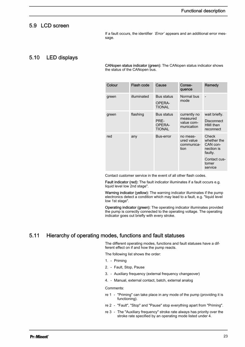
5.9 LCD screenIf a fault occurs, the identifier ‘Error’ appears and an additional error mes‐sage.
5.10 LED displaysCANopen status indicator (green): The CANopen status indicator showsthe status of the CANopen bus.
Colour Flash code Cause Conse‐quence
Remedy
green illuminated Bus status
OPERA‐TIONAL
Normal busmode
-
green flashing Bus status
PRE-OPERA‐TIONAL
currently nomeasuredvalue com‐munication
wait briefly.
DisconnectHMI thenreconnect
red any Bus-error no meas‐ured valuecommunica‐tion
Checkwhether theCAN con‐nection isfaulty.
Contact cus‐tomerservice
Contact customer service in the event of all other flash codes.
Fault indicator (red): The fault indicator illuminates if a fault occurs e.g.liquid level low 2nd stage".
Warning indicator (yellow): The warning indicator illuminates if the pumpelectronics detect a condition which may lead to a fault, e.g. "liquid levellow 1st stage".
Operating indicator (green): The operating indicator illuminates providedthe pump is correctly connected to the operating voltage. The operatingindicator goes out briefly with every stroke.
5.11 Hierarchy of operating modes, functions and fault statusesThe different operating modes, functions and fault statuses have a dif‐ferent effect on if and how the pump reacts.
The following list shows the order:
1. - Priming
2. - Fault, Stop, Pause
3. - Auxiliary frequency (external frequency changeover)
4. - Manual, external contact, batch, external analog
Comments:
re 1 - "Priming" can take place in any mode of the pump (providing it isfunctioning).
re 2 - "Fault", "Stop" and "Pause" stop everything apart from "Priming".
re 3 - The "Auxiliary frequency" stroke rate always has priority over thestroke rate specified by an operating mode listed under 4.
Functional description
23

6 Assembly
Compare the dimensions on the dimensional drawing andpump.
WARNING!Danger of electric shockIf water or other electrically conducting liquids penetrate intothe drive housing, in any other manner than via the pump'ssuction connection, an electric shock may occur.
– Position the pump so that it cannot be flooded.
WARNING!The pump can break through the base or slide off it– Ensure that the base is horizontal, smooth and perma‐
nently load-bearing.
Capacity too lowVibrations can disrupt the liquid end valves.– The supporting floor must not vibrate.
CAUTION!Danger from incorrectly operated or inadequately maintainedpumpsDanger can arise from a poorly accessible pump due toincorrect operation and poor maintenance.
– Ensure that the pump is accessible at all times.– Adhere to the maintenance intervals.
Position the pump so that control elements such as the stroke lengthadjustment knob or the indicating dial A are easily accessible.
If the HMI is mounted at a distance from the pump, fit a clearly markedStop mechanism in the direct vicinity of the pump for emergencies!
1 Discharge valve2 Dosing head3 Suction valve
Ensure that there is sufficient free space (f) around the dosing head, aswell as the suction and discharge valve, so that maintenance and repairwork can easily be carried out on these components.
Base
h
P_MOZ_0016_SW
Fig. 10
Space requirement
A
A
P_MOZ_0018_SW
Fig. 11
1
3
2f
ff
P_MOZ_0017_SW
Fig. 12
Assembly
24
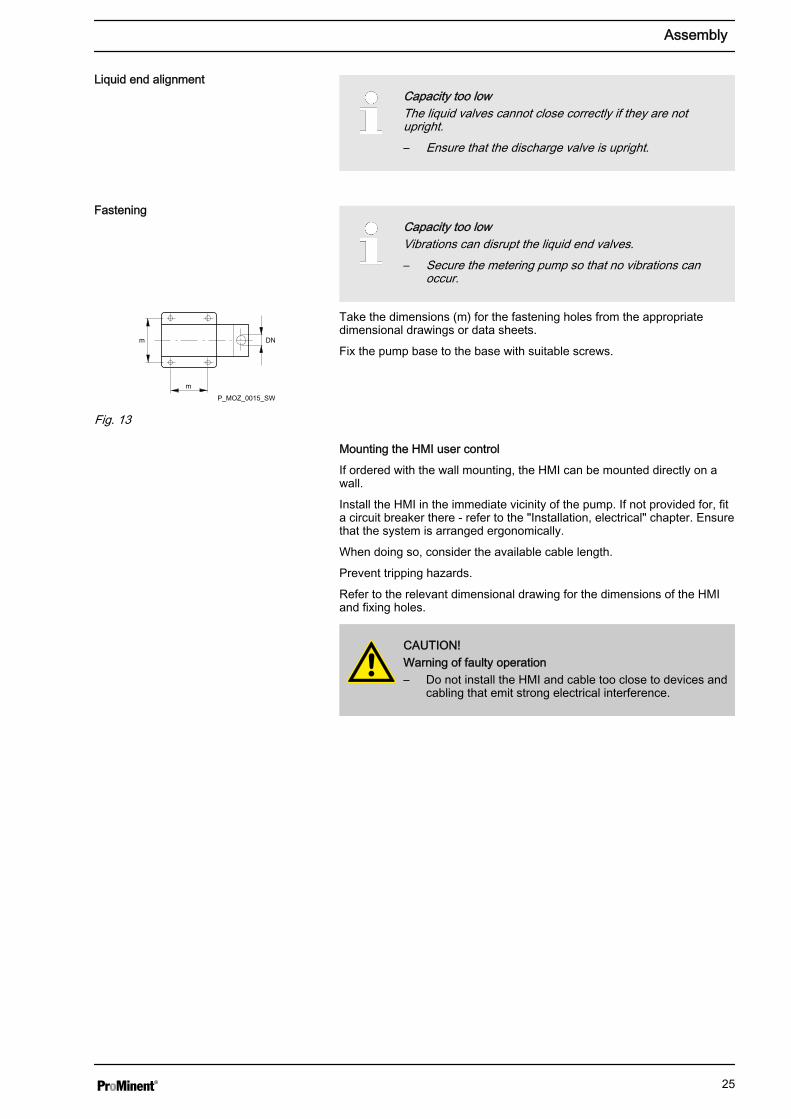
Capacity too lowThe liquid valves cannot close correctly if they are notupright.– Ensure that the discharge valve is upright.
Capacity too lowVibrations can disrupt the liquid end valves.– Secure the metering pump so that no vibrations can
occur.
Take the dimensions (m) for the fastening holes from the appropriatedimensional drawings or data sheets.
Fix the pump base to the base with suitable screws.
Mounting the HMI user control
If ordered with the wall mounting, the HMI can be mounted directly on awall.
Install the HMI in the immediate vicinity of the pump. If not provided for, fita circuit breaker there - refer to the "Installation, electrical" chapter. Ensurethat the system is arranged ergonomically.
When doing so, consider the available cable length.
Prevent tripping hazards.
Refer to the relevant dimensional drawing for the dimensions of the HMIand fixing holes.
CAUTION!Warning of faulty operation– Do not install the HMI and cable too close to devices and
cabling that emit strong electrical interference.
Liquid end alignment
Fastening
DNm
m
P_MOZ_0015_SW
Fig. 13
Assembly
25
7 Installation
CAUTION!Danger of personnel injury and material damageThe disregard of technical data during installation may leadto personal injuries or damage to property.
– Observe the technical data- refer to chapter "TechnicalData" and, where applicable, the operating instructionsof the accessories.
7.1 Installation, hydraulic
WARNING!Danger of fire with flammable feed chemicals– Only metering pumps with the identity code option
"Multi-layer safety diaphragm with rupture signalling withelectrical signal" are permitted to meter flammablemedia, with back pressures over 2 bar and if the oper‐ator takes appropriate safety precautions.
WARNING!Warning of feed chemical reactions to waterFeed chemicals that should not come into contact with watermay react to residual water in the liquid end that may origi‐nate from works testing.
– Blow the liquid end dry with compressed air through thesuction connector.
– Then flush the liquid end with a suitable medium throughthe suction connector.
WARNING!The following measures are an advantage when working withhighly aggressive or hazardous feed chemicals:
– Install a bleed valve with recirculation in the storagetank.
– Install an additional shut-off valve on the discharge orsuction ends.
CAUTION!Warning of feed chemical spraying aroundPTFE seals, which have already been used / compressed,can no longer reliably seal a hydraulic connection.
– New, unused PTFE seals must always be used.
CAUTION!Suction problems possibleThe valves may no longer close properly with feed chemicalswith a particle size of greater than 0.3 mm.
– Install a suitable filter in the suction line.
Installation
26

CAUTION!Warning against the discharge line burstingWith a closed discharge line (e.g. from a clogged dischargeline or by closing a valve), the pressure that the meteringpump generates can reach several times more than the per‐missible pressure of the system or the metering pump. Thiscould lead to lines bursting resulting in dangerous conse‐quences with aggressive or hazardous feed chemicals.
– Install a relief valve that limits the pressure of the pumpto the maximum permissible operating pressure of thesystem.
CAUTION!Warning against bursting of the suction or discharge linesHose lines with insufficient pressure rating may burst.
– Only use hose lines with the required pressure rating.
CAUTION!Uncontrolled flow of feed chemicalFeed chemical can leak through the metering pump in anuncontrolled manner in the event of excessive priming pres‐sure on the suction side of the metering pump.
– Do not exceed the maximum permissible priming pres‐sure for the metering pump.
– Arrange the installation properly.
CAUTION!Warning against lines coming looseIf suction, discharge and relief lines are installed incorrectly,they can loosen / disconnect from the pump connection.
– Only use original hoses with the specified tube diameterand wall thickness.
– Only use clamp rings and hose nozzles that correspondto the respective hose diameter.
– Always connect the lines without mechanical tension.
CAUTION!Warning against leaksLeaks can occur on the pump connection depending on theinsert used.
– The pump is supplied with PTFE moulded compositeseals with a flare, which are used for the pump connec‐tions. They seal the connections between grooved pumpvalves and the grooved inserts from ProMinent - seeÄ on page 26.
– In the event that an unflared insert is used (e.g. thirdparty part), an elastomer flat seal must be used - seeÄ on page 26.
P_SI_0021
Fig. 14: Moulded composite seals withcorrugated insert
Installation
27
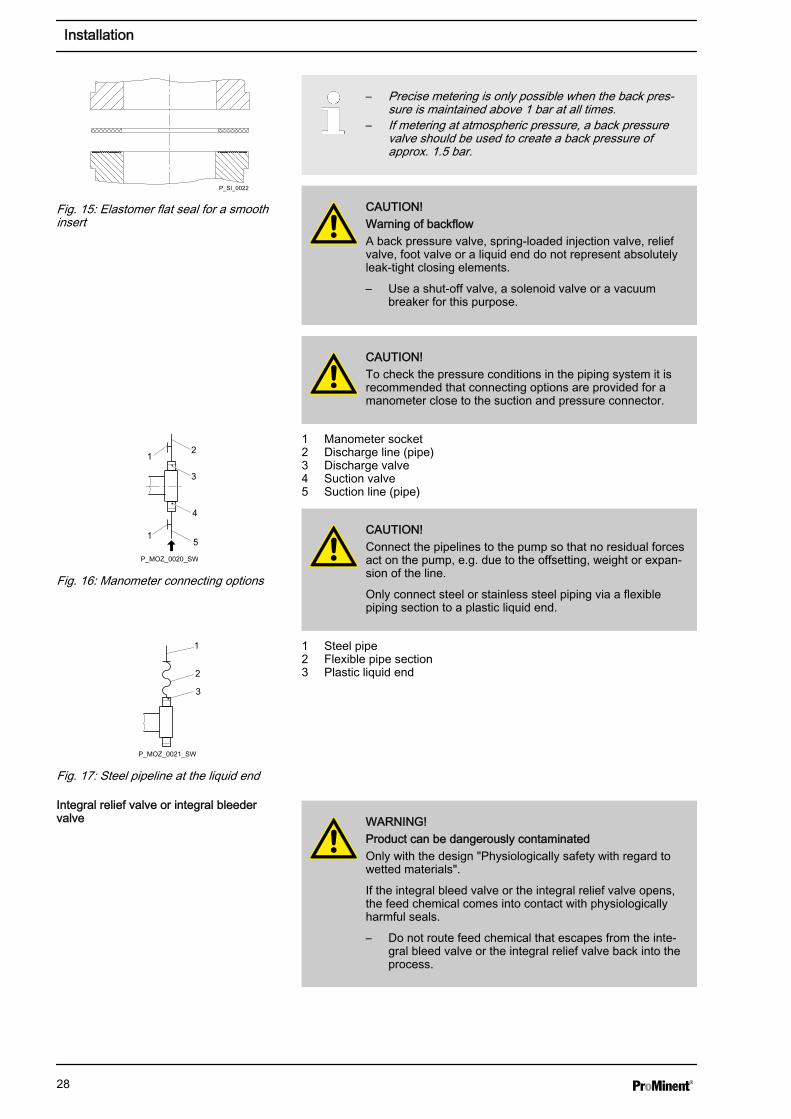
– Precise metering is only possible when the back pres‐sure is maintained above 1 bar at all times.
– If metering at atmospheric pressure, a back pressurevalve should be used to create a back pressure ofapprox. 1.5 bar.
CAUTION!Warning of backflowA back pressure valve, spring-loaded injection valve, reliefvalve, foot valve or a liquid end do not represent absolutelyleak-tight closing elements.
– Use a shut-off valve, a solenoid valve or a vacuumbreaker for this purpose.
CAUTION!To check the pressure conditions in the piping system it isrecommended that connecting options are provided for amanometer close to the suction and pressure connector.
1 Manometer socket2 Discharge line (pipe)3 Discharge valve4 Suction valve5 Suction line (pipe)
CAUTION!Connect the pipelines to the pump so that no residual forcesact on the pump, e.g. due to the offsetting, weight or expan‐sion of the line.
Only connect steel or stainless steel piping via a flexiblepiping section to a plastic liquid end.
1 Steel pipe2 Flexible pipe section3 Plastic liquid end
WARNING!Product can be dangerously contaminatedOnly with the design "Physiologically safety with regard towetted materials".
If the integral bleed valve or the integral relief valve opens,the feed chemical comes into contact with physiologicallyharmful seals.
– Do not route feed chemical that escapes from the inte‐gral bleed valve or the integral relief valve back into theprocess.
P_SI_0022
Fig. 15: Elastomer flat seal for a smoothinsert
1
1
2
3
4
5
P_MOZ_0020_SW
Fig. 16: Manometer connecting options
1
2
3
P_MOZ_0021_SW
Fig. 17: Steel pipeline at the liquid end
Integral relief valve or integral bleedervalve
Installation
28
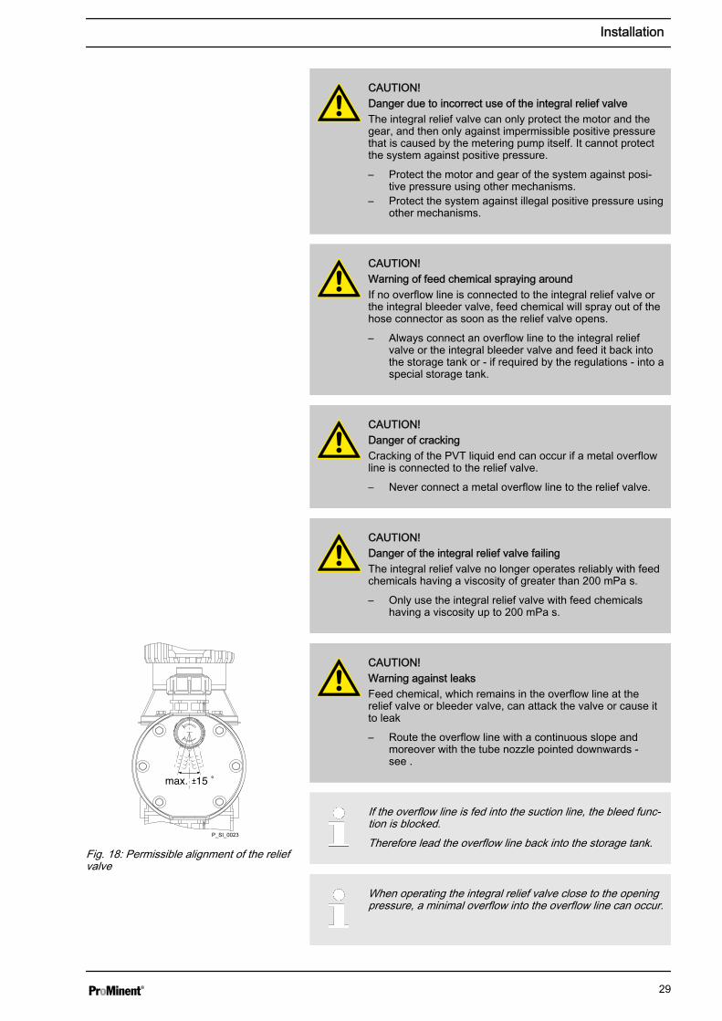
CAUTION!Danger due to incorrect use of the integral relief valveThe integral relief valve can only protect the motor and thegear, and then only against impermissible positive pressurethat is caused by the metering pump itself. It cannot protectthe system against positive pressure.
– Protect the motor and gear of the system against posi‐tive pressure using other mechanisms.
– Protect the system against illegal positive pressure usingother mechanisms.
CAUTION!Warning of feed chemical spraying aroundIf no overflow line is connected to the integral relief valve orthe integral bleeder valve, feed chemical will spray out of thehose connector as soon as the relief valve opens.
– Always connect an overflow line to the integral reliefvalve or the integral bleeder valve and feed it back intothe storage tank or - if required by the regulations - into aspecial storage tank.
CAUTION!Danger of crackingCracking of the PVT liquid end can occur if a metal overflowline is connected to the relief valve.
– Never connect a metal overflow line to the relief valve.
CAUTION!Danger of the integral relief valve failingThe integral relief valve no longer operates reliably with feedchemicals having a viscosity of greater than 200 mPa s.
– Only use the integral relief valve with feed chemicalshaving a viscosity up to 200 mPa s.
CAUTION!Warning against leaksFeed chemical, which remains in the overflow line at therelief valve or bleeder valve, can attack the valve or cause itto leak
– Route the overflow line with a continuous slope andmoreover with the tube nozzle pointed downwards -see .
If the overflow line is fed into the suction line, the bleed func‐tion is blocked.Therefore lead the overflow line back into the storage tank.
When operating the integral relief valve close to the openingpressure, a minimal overflow into the overflow line can occur.
P_SI_0023
Fig. 18: Permissible alignment of the reliefvalve
Installation
29
CAUTION!Danger resulting from unnoticed diaphragm ruptureIf the pump has been ordered with an electric diaphragm rup‐ture sensor, it still has to be installed.
– Screw the enclosed diaphragm rupture sensor into theliquid end.
CAUTION!Warning of unnoticed diaphragm ruptureOnly above approximately 2 bar system back pressure is asignal generated upon a diaphragm rupture.
– Only rely on the diaphragm rupture sensor at back pres‐sures greater than 2 bar.
7.1.1 Basic installation notes
CAUTION!Danger resulting from rupturing hydraulic componentsHydraulic components can rupture if the maximum permis‐sible operating pressure is exceeded.
– Never allow the metering pump to run against a closedshut-off device.
– With metering pumps without integral relief valve: Installa relief valve in the discharge line.
CAUTION!Hazardous feed chemicals can escapeWith hazardous feed chemicals: Hazardous feed chemicalcan leak out when using conventional bleeding procedureswith metering pumps.
– Install a bleed line with a return into the storage tank.
Shorten the return line so that it does not dip into the feed chemicalin the storage tank.
Diaphragm rupture sensor
Safety notes
Installation
30
P_MOZ_0043_SW
2
1
A) B)
*PD
1
2
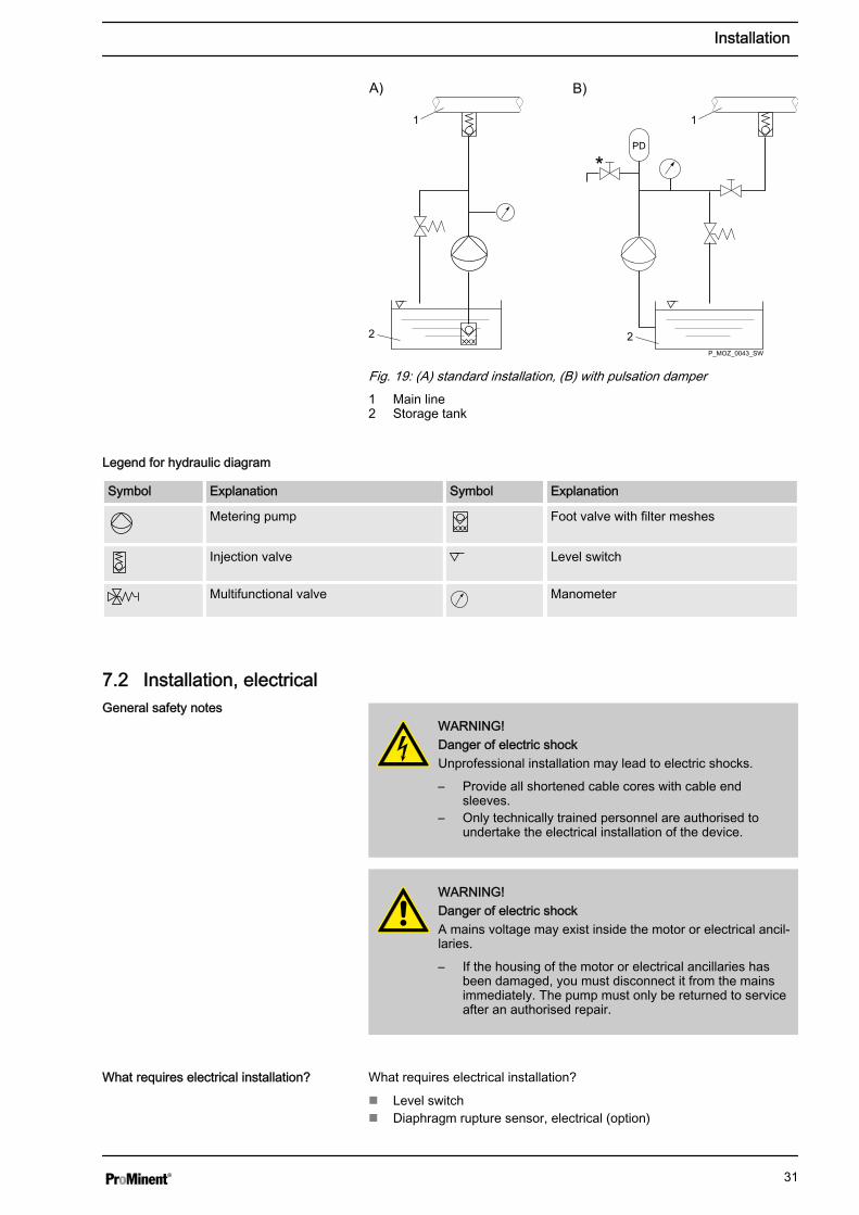
Fig. 19: (A) standard installation, (B) with pulsation damper1 Main line2 Storage tank
Symbol Explanation Symbol Explanation
Metering pump Foot valve with filter meshes
Injection valve Level switch
Multifunctional valve Manometer
7.2 Installation, electrical
WARNING!Danger of electric shockUnprofessional installation may lead to electric shocks.
– Provide all shortened cable cores with cable endsleeves.
– Only technically trained personnel are authorised toundertake the electrical installation of the device.
WARNING!Danger of electric shockA mains voltage may exist inside the motor or electrical ancil‐laries.
– If the housing of the motor or electrical ancillaries hasbeen damaged, you must disconnect it from the mainsimmediately. The pump must only be returned to serviceafter an authorised repair.
What requires electrical installation?
n Level switchn Diaphragm rupture sensor, electrical (option)
Legend for hydraulic diagram
General safety notes
What requires electrical installation?
Installation
31

n Dosing monitor (option)n Relay (option)n External controln mA output (option)n Bus connector (option)n Timer (option)n Pump, power supply
7.2.1 Control connectors
CAUTION!Incoming signals can remain without effectIf the universal control wire, the external/pacing cable or thelevel monitoring cable is shortened below 1.20 m, the pumpdoes not detect that it is connected. Consequently a warningmessage (for example) can be suppressed.
– Do not shorten this cable below 1.20 m.
Connect the plugs of the level switch, diaphragm rupture sensor anddosing monitor to the corresponding sockets on the front side of the con‐trol. In case of uncertainty - see chapter "Overview of equipment and con‐trol elements"
CAUTION!Danger resulting from unnoticed diaphragm ruptureIf the pump has been ordered with an electric diaphragm rup‐ture sensor, it must also be electrically installed.
– Electrically connect the enclosed diaphragm rupturesensor.
Only with combustible media:
WARNING!Fire dangerThe electric diaphragm rupture sensor must stop the pumpimmediately after a diaphragm rupture and trigger an alarm.
The pump must only be returned to service once a new dia‐phragm has been fitted.
Level switch, diaphragm rupture sensor(option) and dosing monitor (option)
Installation
32
7.2.1.1 Relay
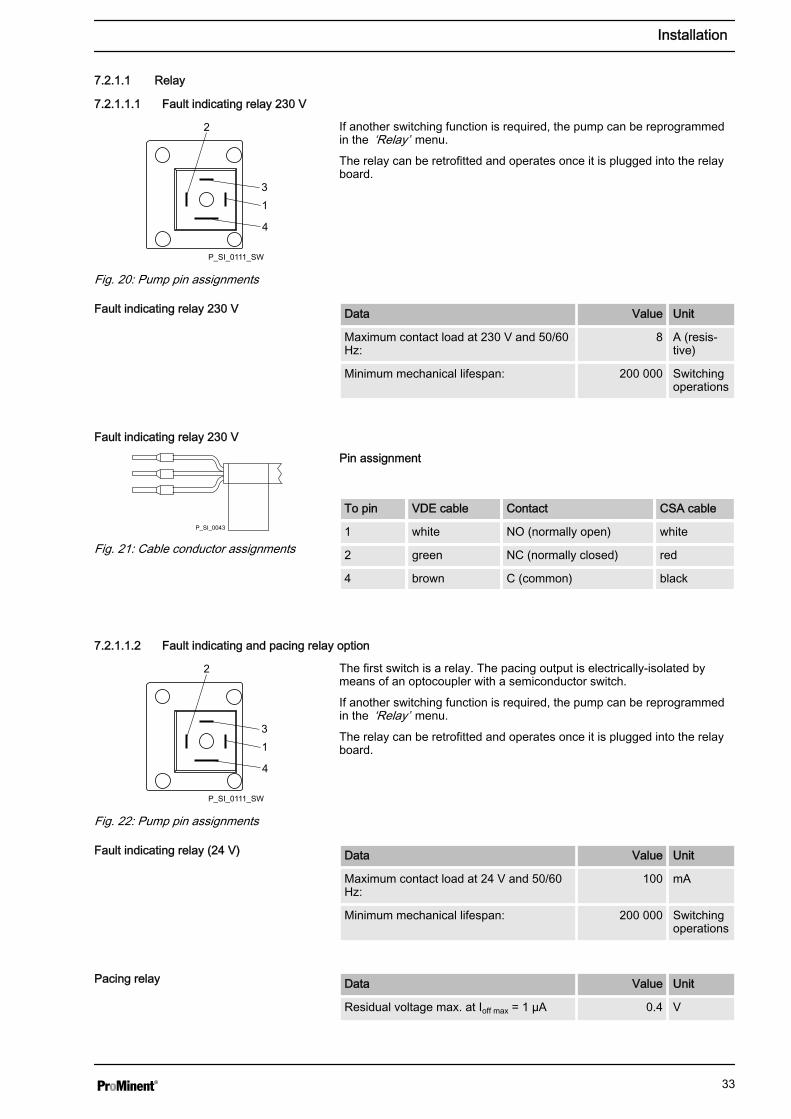
7.2.1.1.1 Fault indicating relay 230 V
If another switching function is required, the pump can be reprogrammedin the ‘Relay’ menu.
The relay can be retrofitted and operates once it is plugged into the relayboard.
Data Value Unit
Maximum contact load at 230 V and 50/60Hz:
8 A (resis‐tive)
Minimum mechanical lifespan: 200 000 Switchingoperations
Pin assignment
To pin VDE cable Contact CSA cable
1 white NO (normally open) white
2 green NC (normally closed) red
4 brown C (common) black
7.2.1.1.2 Fault indicating and pacing relay option
The first switch is a relay. The pacing output is electrically-isolated bymeans of an optocoupler with a semiconductor switch.
If another switching function is required, the pump can be reprogrammedin the ‘Relay’ menu.
The relay can be retrofitted and operates once it is plugged into the relayboard.
Data Value Unit
Maximum contact load at 24 V and 50/60Hz:
100 mA
Minimum mechanical lifespan: 200 000 Switchingoperations
Data Value Unit
Residual voltage max. at Ioff max = 1 µA 0.4 V
2
31
4
P_SI_0111_SW
Fig. 20: Pump pin assignments
Fault indicating relay 230 V
Fault indicating relay 230 V
P_SI_0043
Fig. 21: Cable conductor assignments
2
31
4
P_SI_0111_SW
Fig. 22: Pump pin assignments
Fault indicating relay (24 V)
Pacing relay
Installation
33
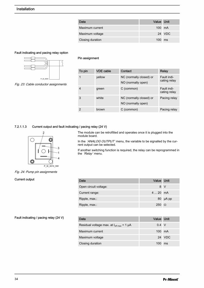
Data Value Unit
Maximum current 100 mA
Maximum voltage 24 VDC
Closing duration 100 ms
Pin assignment
To pin VDE cable Contact Relay
1 yellow NC (normally closed) or
NO (normally open)
Fault indi‐cating relay
4 green C (common) Fault indi‐cating relay
3 white NC (normally closed) or
NO (normally open)
Pacing relay
2 brown C (common) Pacing relay
7.2.1.1.3 Current output and fault indicating / pacing relay (24 V)
The module can be retrofitted and operates once it is plugged into themodule board.
In the ‘ANALOG OUTPUT’ menu, the variable to be signalled by the cur‐rent output can be selected.
If another switching function is required, the relay can be reprogrammed inthe ‘Relay’ menu.
Data Value Unit
Open circuit voltage: 8 V
Current range: 4 ... 20 mA
Ripple, max.: 80 μA pp
Ripple, max.: 250 Ω
Data Value Unit
Residual voltage max. at Ioff max = 1 µA 0.4 V
Maximum current 100 mA
Maximum voltage 24 VDC
Closing duration 100 ms
Fault indicating and pacing relay option
P_SI_0044
Fig. 23: Cable conductor assignments
2
31
4
P_SI_0010_SW
Fig. 24: Pump pin assignments
Current output
Fault indicating / pacing relay (24 V)
Installation
34
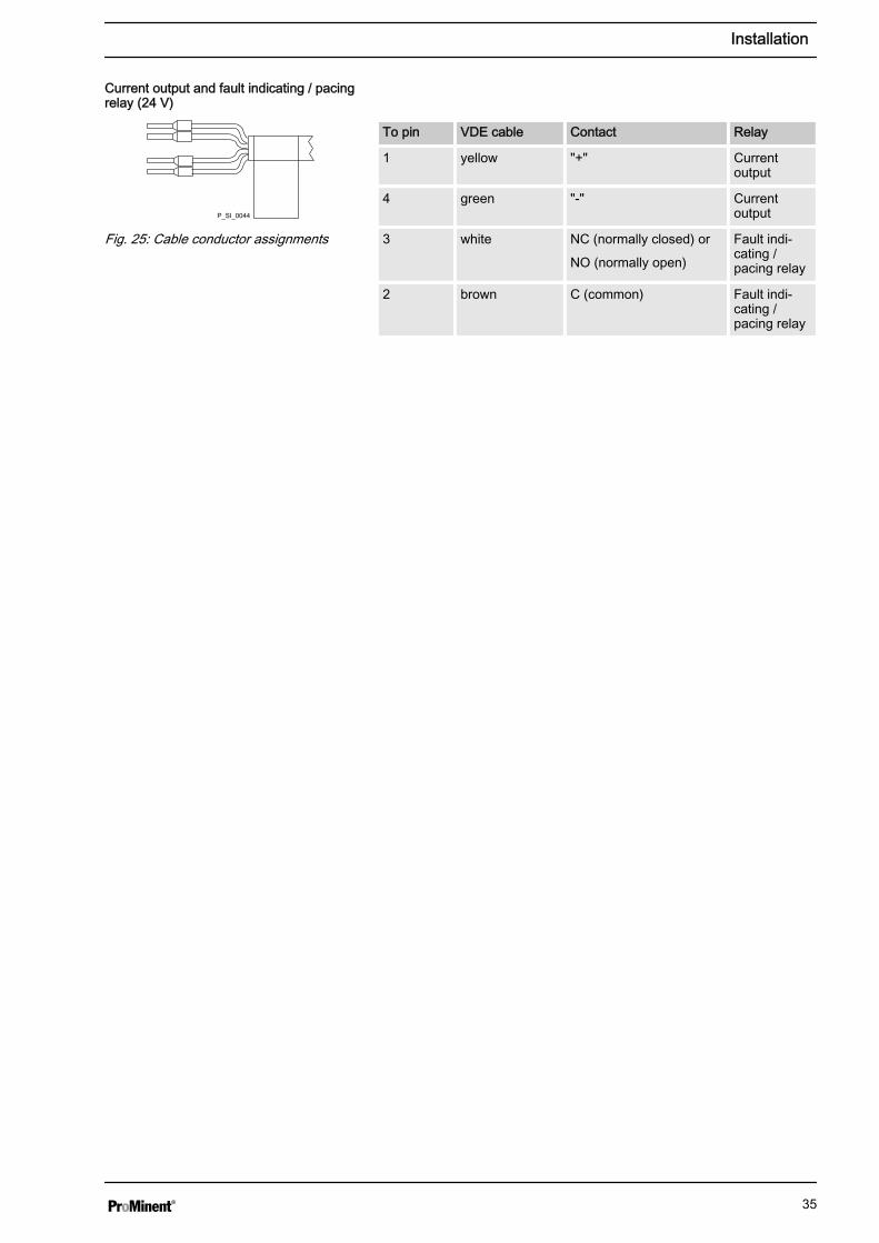
To pin VDE cable Contact Relay
1 yellow "+" Currentoutput
4 green "-" Currentoutput
3 white NC (normally closed) or
NO (normally open)
Fault indi‐cating /pacing relay
2 brown C (common) Fault indi‐cating /pacing relay
Current output and fault indicating / pacingrelay (24 V)
P_SI_0044
Fig. 25: Cable conductor assignments
Installation
35
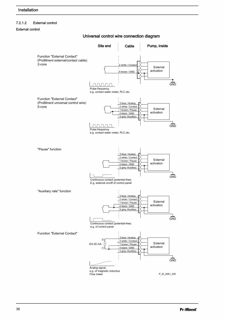
7.2.1.2 External control
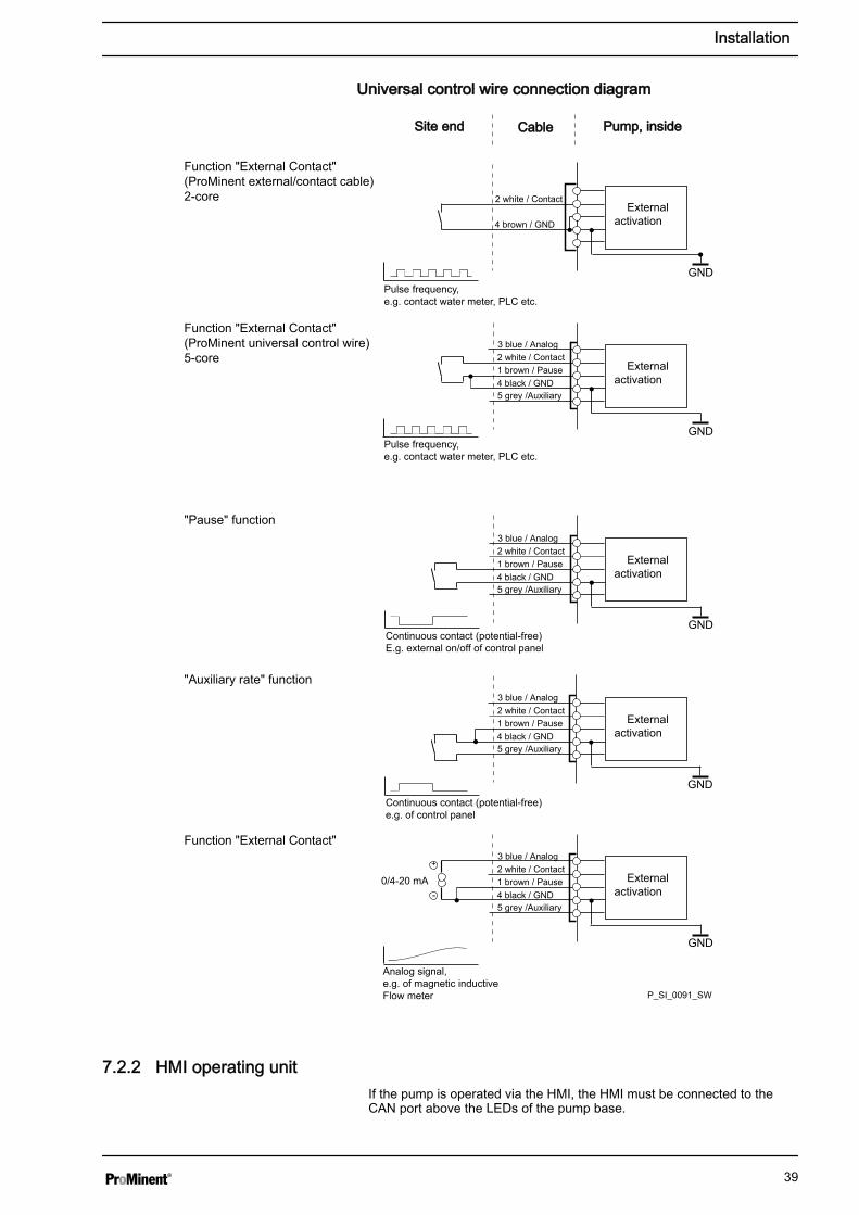
Universal control wire connection diagramUniversal control wire connection diagram
Site endSite end CableCable Pump, insidePump, inside
2 white / Contact
4 brown / GND
GND
Externalactivation
Function "External Contact"(ProMinent external/contact cable)2-core
1 brown / Pause2 white / Contact
4 black / GND
3 blue / Analog
5 grey /Auxiliary
GND
GND
Externalactivation
1 brown / Pause2 white / Contact
4 black / GND
3 blue / Analog
5 grey /Auxiliary
Externalactivation
1 brown / Pause2 white / Contact
4 black / GND
3 blue / Analog
5 grey /Auxiliary
Externalactivation
1 brown / Pause2 white / Contact
4 black / GND
3 blue / Analog
5 grey /Auxiliary
Externalactivation
GND
GND
+
-
Function "External Contact"(ProMinent universal control wire)5-core
"Pause" function
"Auxiliary rate" function
Function "External Contact"
Pulse frequency,e.g. contact water meter, PLC etc.
Pulse frequency,e.g. contact water meter, PLC etc.
Continuous contact (potential-free)E.g. external on/off of control panel
Continuous contact (potential-free)e.g. of control panel
0/4-20 mA
Analog signal,e.g. of magnetic inductiveFlow meter P_SI_0091_SW
External control
Installation
36
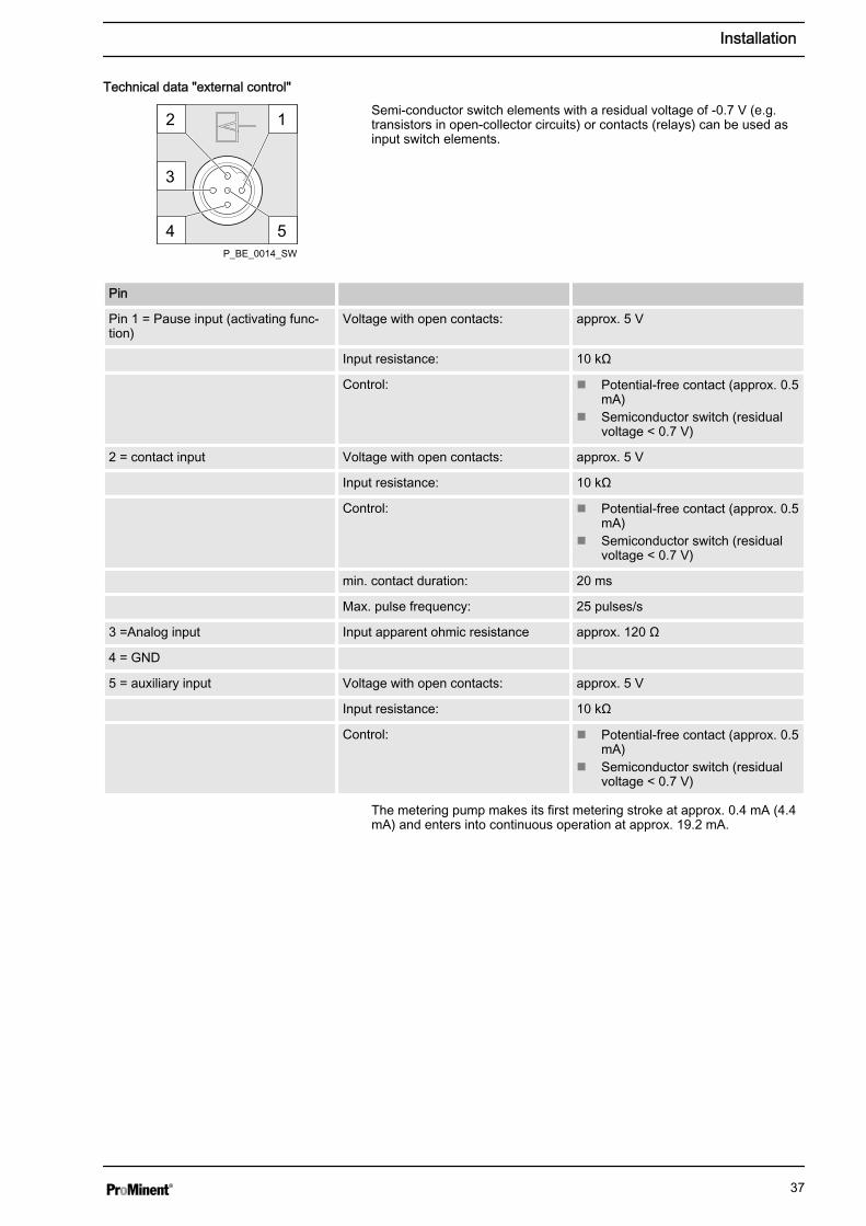
Semi-conductor switch elements with a residual voltage of -0.7 V (e.g.transistors in open-collector circuits) or contacts (relays) can be used asinput switch elements.
Pin
Pin 1 = Pause input (activating func‐tion)
Voltage with open contacts: approx. 5 V
Input resistance: 10 kΩ
Control: n Potential-free contact (approx. 0.5mA)
n Semiconductor switch (residualvoltage < 0.7 V)
2 = contact input Voltage with open contacts: approx. 5 V
Input resistance: 10 kΩ
Control: n Potential-free contact (approx. 0.5mA)
n Semiconductor switch (residualvoltage < 0.7 V)
min. contact duration: 20 ms
Max. pulse frequency: 25 pulses/s
3 =Analog input Input apparent ohmic resistance approx. 120 Ω
4 = GND
5 = auxiliary input Voltage with open contacts: approx. 5 V
Input resistance: 10 kΩ
Control: n Potential-free contact (approx. 0.5mA)
n Semiconductor switch (residualvoltage < 0.7 V)
The metering pump makes its first metering stroke at approx. 0.4 mA (4.4mA) and enters into continuous operation at approx. 19.2 mA.
Technical data "external control"
1
54
2
3
P_BE_0014_SW
Installation
37
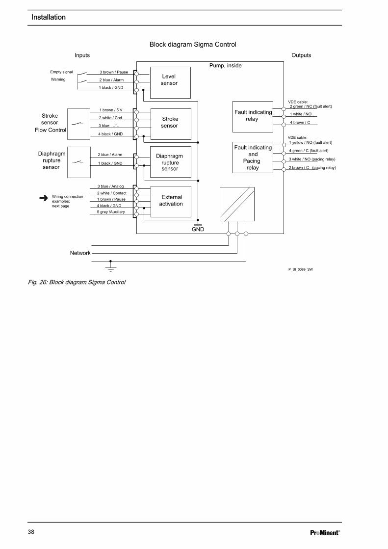
GND
Inputs Outputs
Pump, inside
Block diagram Sigma Control
Externalactivation
Diaphragm rupturesensor
Strokesensor
Levelsensor
Fault indicatingrelay
Warning
Network
Wiring connectionexamples:next page
Strokesensor
Flow Control
Diaphragmrupturesensor
3 white / NO (pacing relay)
Fault indicatingand
Pacing relay
VDE cable:
Empty signal
2 brown / C (pacing relay)
1 white / NO
4 brown / C
1 yellow / NO (fault alert)
4 green / C (fault alert)
2 green / NC (fault alert)
3 brown / Pause
2 blue / Alarm
1 black / GND
1 brown / 5 V
2 white / Cod.
4 black / GND
3 blue
2 blue / Alarm
1 black / GND
VDE cable:
1 brown / Pause2 white / Contact
4 black / GND
3 blue / Analog
5 grey /Auxiliary
P_SI_0089_SW
Fig. 26: Block diagram Sigma Control
Installation
38
Universal control wire connection diagramUniversal control wire connection diagram
Site endSite end CableCable Pump, insidePump, inside
2 white / Contact
4 brown / GND
GND
Externalactivation
Function "External Contact"(ProMinent external/contact cable)2-core
1 brown / Pause2 white / Contact
4 black / GND
3 blue / Analog
5 grey /Auxiliary
GND
GND
Externalactivation
1 brown / Pause2 white / Contact
4 black / GND
3 blue / Analog
5 grey /Auxiliary
Externalactivation
1 brown / Pause2 white / Contact
4 black / GND
3 blue / Analog
5 grey /Auxiliary
Externalactivation
1 brown / Pause2 white / Contact
4 black / GND
3 blue / Analog
5 grey /Auxiliary
Externalactivation
GND
GND
+
-
Function "External Contact"(ProMinent universal control wire)5-core
"Pause" function
"Auxiliary rate" function
Function "External Contact"
Pulse frequency,e.g. contact water meter, PLC etc.
Pulse frequency,e.g. contact water meter, PLC etc.
Continuous contact (potential-free)E.g. external on/off of control panel
Continuous contact (potential-free)e.g. of control panel
0/4-20 mA
Analog signal,e.g. of magnetic inductiveFlow meter P_SI_0091_SW
7.2.2 HMI operating unitIf the pump is operated via the HMI, the HMI must be connected to theCAN port above the LEDs of the pump base.
Installation
39
If the pump is operated without the HMI, the supplied sealing cap must beplugged into the CAN port above the LEDs of the pump base.
CAUTION!Risk of short circuitIf liquid penetrates into the CAN port, a short circuit mayoccur in the pump.
– A CAN plug or the supplied sealing cap must always beplugged into the CAN port.
CAUTION!Danger of malfunctionsIncorrect operation via the CAN bus leads to malfunctions.
– When operating with the HMI connected, do not connectany other control (e.g. DXCa) to the CAN port.
7.2.3 Pump, power supply
WARNING!Risk of electric shockThis pump is supplied with a grounding conductor and agrounding-type attachment plug.
– To reduce the risk of electric shock, ensure that it is con‐nected only to a proper grounding-type receptacle.
WARNING!Danger of electric shockIn the event of an electrical accident, it must be possible toquickly disconnect the pump, and any electrical ancillarieswhich may possibly be present, from the mains.
– Install an emergency cut-off switch in the mains supplyline to the pump and any electrical ancillaries which maybe present or
– Integrate the pump and electrical ancillaries which maybe present in the emergency cut-off management of thesystem and inform personnel of the isolating option.
WARNING!If the HMI cannot be operated directly from the pump (specif‐ically with versions with a cable longer than 2 m), provide anoption to disconnect the pump from the mains power supplyin the event of an emergency. Clearly assign and label thisoption to the pump.
WARNING!An on/off switch may not be fitted on the pump, dependenton the identity code and installation.
Installation
40
To be able to switch off the pump (to a zero-volts state) inde‐pendently from the entire installation (e.g. for repair), use anelectrical isolating device in the mains supply cable, e.g. amains switch or a plug / socket combination. Clearly identifythis isolating device as such.
Install the pump cable.
– Key electrical data can be found on the pump name‐plate.
7.2.4 Other units
Install the other units according to their supplied documentation.
Other units
Installation
41
8 Set up
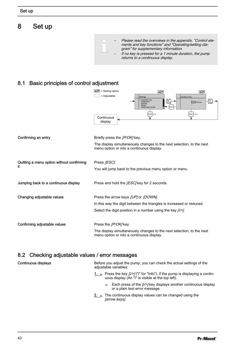
– Please read the overviews in the appendix, "Control ele‐ments and key functions" and "Operating/setting dia‐gram" for supplementary information.
– If no key is pressed for a 1 minute duration, the pumpreturns to a continuous display.
8.1 Basic principles of control adjustment
Continuousdisplay
Auxiliary freq.
070 /min
SettingsAuxiliary freq.CalibrationDosingRelayDiaphragm break
= Adjustable
= Setting option
2 s 2 s
Briefly press the [P/OK] key.
The display simultaneously changes to the next selection, to the nextmenu option or into a continuous display.
Press [ESC].You will jump back to the previous menu option or menu.
Press and hold the [ESC] key for 2 seconds.
Press the arrow keys [UP] or [DOWN].In this way the digit between the triangles is increased or reduced.
Select the digit position in a number using the key [i/>].
Press the [P/OK] key.
The display simultaneously changes to the next selection, to the nextmenu option or into a continuous display.
8.2 Checking adjustable values / error messagesBefore you adjust the pump, you can check the actual settings of theadjustable variables:
1. Press the key [i/>] ("i" for "Info"), if the pump is displaying a contin‐uous display (An "i" is visible at the top left).
ð Each press of the [i/>] key displays another continuous displayor a plain text error message.
2. The continuous display values can be changed using the[arrow keys].
Confirming an entry
Quitting a menu option without confirmingit
Jumping back to a continuous display
Changing adjustable values
Confirming adjustable values
Continuous displays
Set up
42
The number of continuous displays depends on the identitycode, the selected operating mode and the connected addi‐tional devices, see overview "Continuous displays" in theappendix.A horizontal scroll bar shows the number of continuous dis‐plays and error messages and the position of the displayedcontinuous display or error message.With error messages an identifier appears while displays withclear text appear between the continuous displays (and anerror code).
The lowest line of the Info displays (2nd level continuous display) variousinformation, which cannot however be adjusted here, see overview "Sec‐ondary displays" in the appendix.
If you are in a continuous display, you can access the bottom line of theinfo displays by:
1. Keep key [i/>] pressed down until a small triangle appears in thebottom line.
2. Now quickly press the [i/>] key to page through the info displays ofthe bottom line.
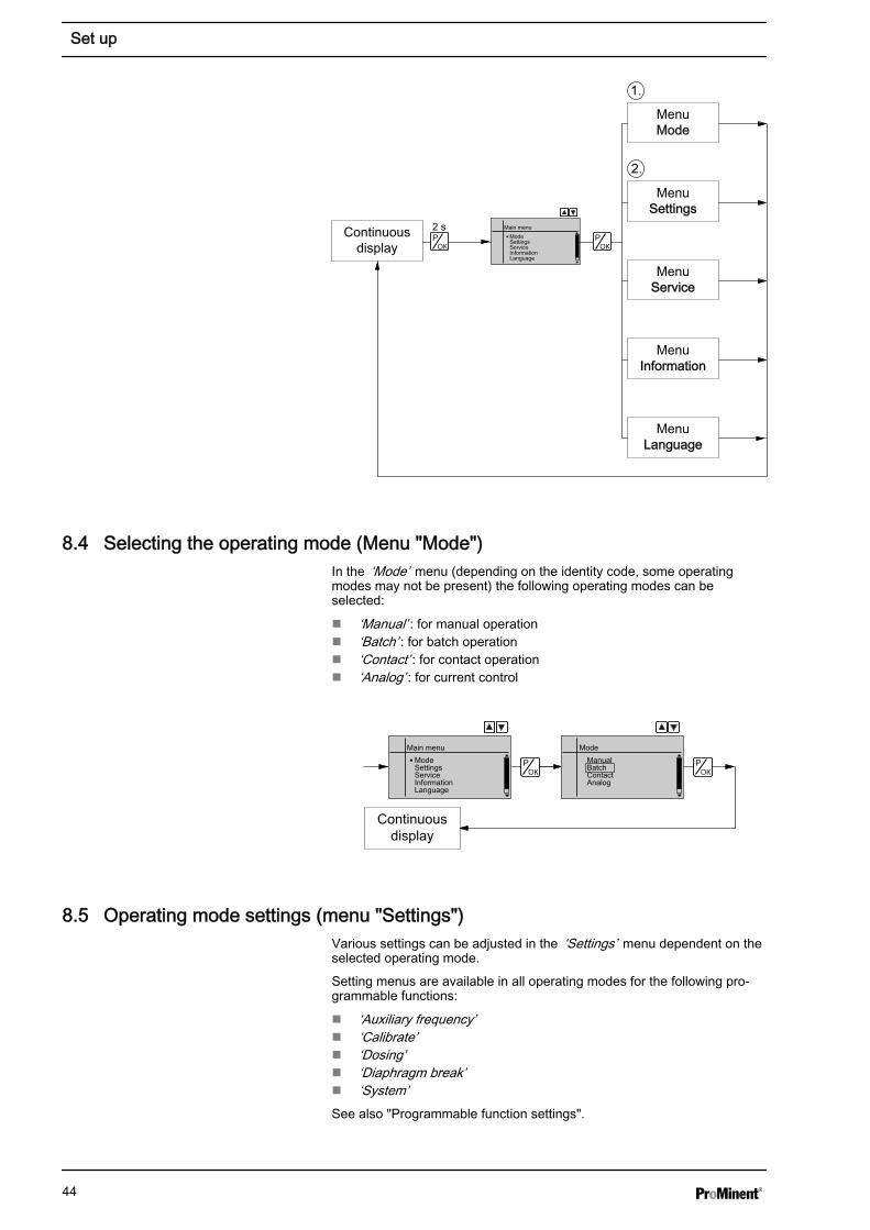
8.3 Changing to adjustment modeIf the [P/OK] key is pressed for 2 seconds in a continuous display, thepump changes to adjustment mode.
If under ‘Service è Safety è Access protection’ ‘Lock menu’ or ‘Lock all’was set (top left key symbol instead of "i"), proceed as follows:
1. Press the [P/OK] key.
ð The ‘Password’ display appears.
2. Enter the password ([Arrow keys]!) and confirm with the [P/OK] key.
ð The ‘Password valid’ display appears.
3. Confirm the display with the [P/OK] key.
ð The ‘Main menu’ appears.
The following menus can be initially chosen in adjustment mode - see alsothe overview "Operating/setting diagram":
n Menu ‘Mode’n Menu ‘Settings’n Menu ‘Service’n Menu ‘Information’n Menu ‘Language’
To adapt the pump to your process requirements, you must:
1. Select the operating mode in the ‘Mode’ menu.
2. Carry out the adjustment for this operating mode under the‘Settings’ menu.
Secondary displays
Set up
43
2 sContinuousdisplay
MenuMode
MenuService
MenuSettings
MenuInformation
1.
2.
MenuLanguage
Main menuModeSettingsServiceInformationLanguage
8.4 Selecting the operating mode (Menu "Mode")In the ‘Mode’ menu (depending on the identity code, some operatingmodes may not be present) the following operating modes can beselected:
n ‘Manual’ : for manual operationn ‘Batch’ : for batch operationn ‘Contact’ : for contact operationn ‘Analog’ : for current control
Continuousdisplay
Main menuModeSettingsServiceInformationLanguage
ModeManualBatchContactAnalog
8.5 Operating mode settings (menu "Settings")Various settings can be adjusted in the ‘Settings’ menu dependent on theselected operating mode.
Setting menus are available in all operating modes for the following pro‐grammable functions:
n ‘Auxiliary frequency’n ‘Calibrate’n ‘Dosing’n ‘Diaphragm break’n ‘System’See also "Programmable function settings".
Set up
44
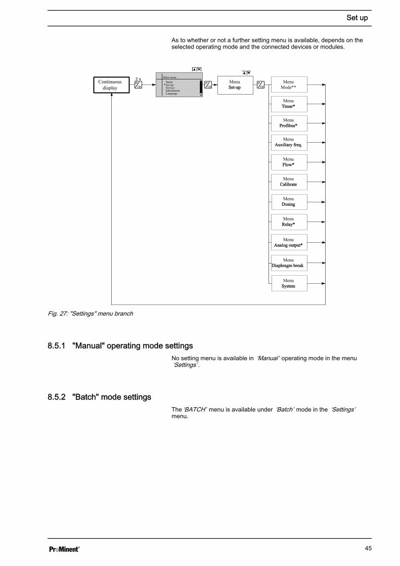
As to whether or not a further setting menu is available, depends on theselected operating mode and the connected devices or modules.
Continuousdisplay
MenuSet-upSet-up
MenuMode**
MenuTimer*Timer*
MenuProfibus*Profibus*
MenuAuxiliary freq.Auxiliary freq.
MenuFlow*Flow*
MenuCalibrateCalibrate
MenuDosingDosing
MenuRelay*Relay*
MenuAnalog output*Analog output*
MenuDiaphragm breakDiaphragm break
MenuSystemSystem
Main menuModeSet-upServiceInformationLanguage
Fig. 27: "Settings" menu branch
8.5.1 "Manual" operating mode settingsNo setting menu is available in ‘Manual’ operating mode in the menu‘Settings’ .
8.5.2 "Batch" mode settings The ‘BATCH’ menu is available under ‘Batch’ mode in the ‘Settings’menu.
Set up
45
Continuousdisplay
Memory
OffOn
Main menuModeSettingsServiceInformationLanguage
SettingsBatchAuxiliary freq.CalibrateDosingRelay
BatchMemoryFactorEnd
5
FactorBatchMemoryFactorEnd
5 0 0 0 0 5
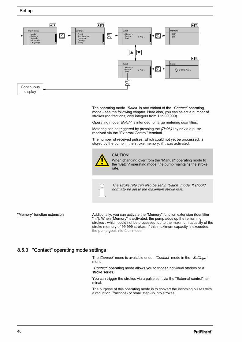
The operating mode ‘Batch’ is one variant of the ‘Contact’ operatingmode - see the following chapter. Here also, you can select a number ofstrokes (no fractions, only integers from 1 to 99,999).
Operating mode ‘Batch’ is intended for large metering quantities.
Metering can be triggered by pressing the [P/OK] key or via a pulsereceived via the "External Control" terminal.
The number of received pulses, which could not yet be processed, isstored by the pump in the stroke memory, if it was activated.
CAUTION!When changing over from the "Manual" operating mode tothe "Batch" operating mode, the pump maintains the strokerate.
The stroke rate can also be set in ‘Batch’ mode. It shouldnormally be set to the maximum stroke rate.
Additionally, you can activate the "Memory" function extension (Identifier"m"). When "Memory" is activated, the pump adds up the remainingstrokes , which could not be processed, up to the maximum capacity of thestroke memory of 99,999 strokes. If this maximum capacity is exceeded,the pump goes into fault mode.
8.5.3 "Contact" operating mode settingsThe ‘Contact’ menu is available under ‘Contact’ mode in the ‘Settings’menu.
‘Contact’ operating mode allows you to trigger individual strokes or astroke series.
You can trigger the strokes via a pulse sent via the "External control" ter‐minal.
The purpose of this operating mode is to convert the incoming pulses witha reduction (fractions) or small step-up into strokes.
"Memory" function extension
Set up
46
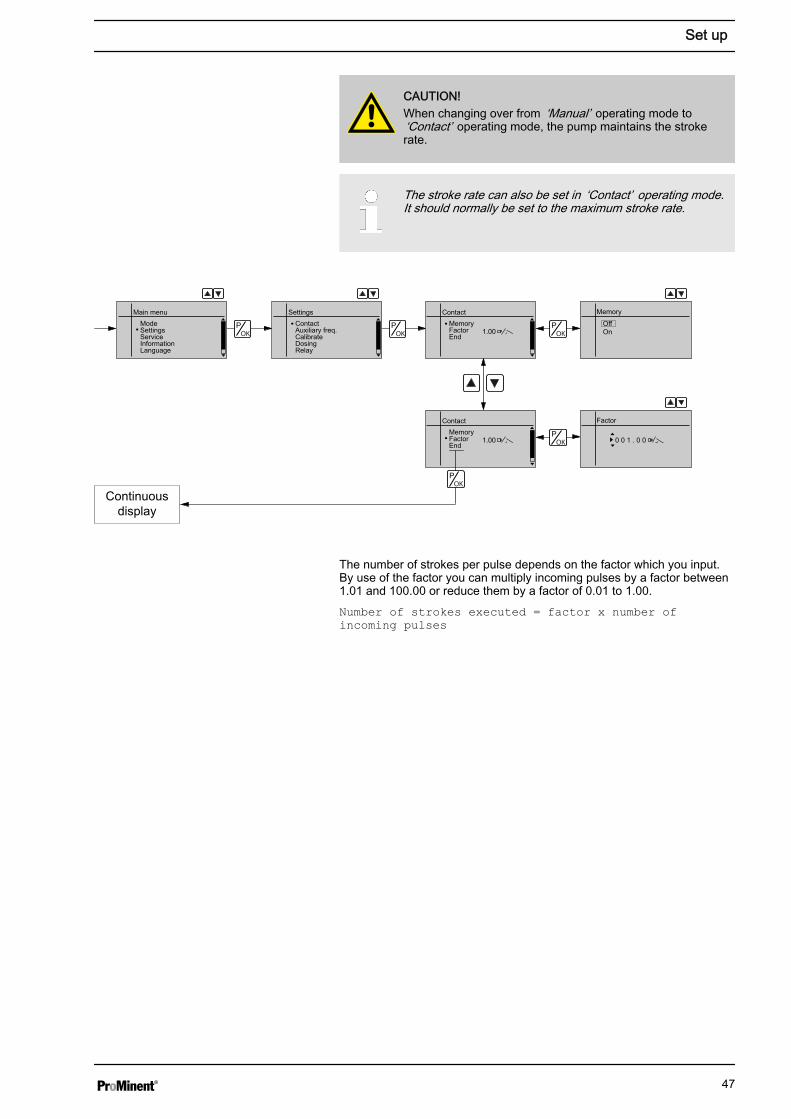
CAUTION!When changing over from ‘Manual’ operating mode to‘Contact’ operating mode, the pump maintains the strokerate.
The stroke rate can also be set in ‘Contact’ operating mode.It should normally be set to the maximum stroke rate.
Continuousdisplay
Memory
OffOn
Main menuModeSettingsServiceInformationLanguage
SettingsContactAuxiliary freq.CalibrateDosingRelay
ContactMemoryFactorEnd
1.00
FactorContactMemoryFactorEnd
1.00 0 0 1 . 0 0
The number of strokes per pulse depends on the factor which you input.By use of the factor you can multiply incoming pulses by a factor between1.01 and 100.00 or reduce them by a factor of 0.01 to 1.00.Number of strokes executed = factor x number ofincoming pulses
Set up
47
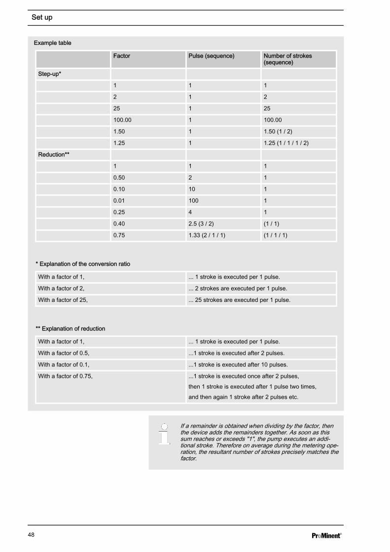
Factor Pulse (sequence) Number of strokes(sequence)
Step-up*
1 1 1
2 1 2
25 1 25
100.00 1 100.00
1.50 1 1.50 (1 / 2)
1.25 1 1.25 (1 / 1 / 1 / 2)
Reduction**
1 1 1
0.50 2 1
0.10 10 1
0.01 100 1
0.25 4 1
0.40 2.5 (3 / 2) (1 / 1)
0.75 1.33 (2 / 1 / 1) (1 / 1 / 1)
* Explanation of the conversion ratio
With a factor of 1, ... 1 stroke is executed per 1 pulse.
With a factor of 2, ... 2 strokes are executed per 1 pulse.
With a factor of 25, ... 25 strokes are executed per 1 pulse.
** Explanation of reduction
With a factor of 1, ... 1 stroke is executed per 1 pulse.
With a factor of 0.5, ...1 stroke is executed after 2 pulses.
With a factor of 0.1, ...1 stroke is executed after 10 pulses.
With a factor of 0.75, ...1 stroke is executed once after 2 pulses,
then 1 stroke is executed after 1 pulse two times,
and then again 1 stroke after 2 pulses etc.
Example table
If a remainder is obtained when dividing by the factor, thenthe device adds the remainders together. As soon as thissum reaches or exceeds "1", the pump executes an addi‐tional stroke. Therefore on average during the metering ope‐ration, the resultant number of strokes precisely matches thefactor.
Set up
48
The number of received pulses, which could not yet be processed, isstored by the device in the stroke memory, if it was activated. When the[STOP/START] key is pressed or the "Pause" function is activated, thestroke memory is deleted. You can avoid this with the "Memory" functionextension:
Additionally, you can activate the "Memory" function extension (Identifier"m"). When "Memory" is activated, the pump adds up the remainingstrokes , which could not be processed, up to the maximum capacity of thestroke memory of 99,999 strokes. If this maximum capacity is exceeded,the pump goes into fault mode.
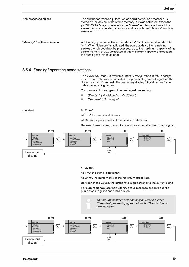
8.5.4 "Analog" operating mode settingsThe ‘ANALOG’ menu is available under ‘Analog’ mode in the ‘Settings’menu. The stroke rate is controlled using an analog current signal via the"External control" terminal. The secondary display "Signal current" indi‐cates the incoming current.
You can select three types of current signal processing:
n ‘Standard’ ( ‘0 - 20 mA’ or ‘4 - 20 mA’ )n ‘Extended’ ( ‘Curve type’ )
0 - 20 mA
At 0 mA the pump is stationary -
At 20 mA the pump works at the maximum stroke rate.
Between these values, the stroke rate is proportional to the current signal.
Standard
0..20mA4..20mA
Main menuModeSettingsServiceInformationLanguage
SettingsAnalogAuxiliary freq.CalibrateDosingRelay
AnalogStandardExtendedEnd
Continuousdisplay
4 - 20 mA
At 4 mA the pump is stationary -
At 20 mA the pump works at the maximum stroke rate.
Between these values, the stroke rate is proportional to the current signal.
For current signals less than 3.8 mA a fault message appears and thepump stops (e.g. if a cable has broken).
The maximum stroke rate can only be reduced under‘Extended’ processing types, not under ‘Standard’ pro‐cessing types.
Standard
0..20mA4..20mA
Main menuModeSettingsServiceInformationLanguage
SettingsAnalogAuxiliary freq.CalibrateDosingRelay
AnalogStandardExtendedEnd
Continuousdisplay
Non-processed pulses
"Memory" function extension
Standard
Set up
49
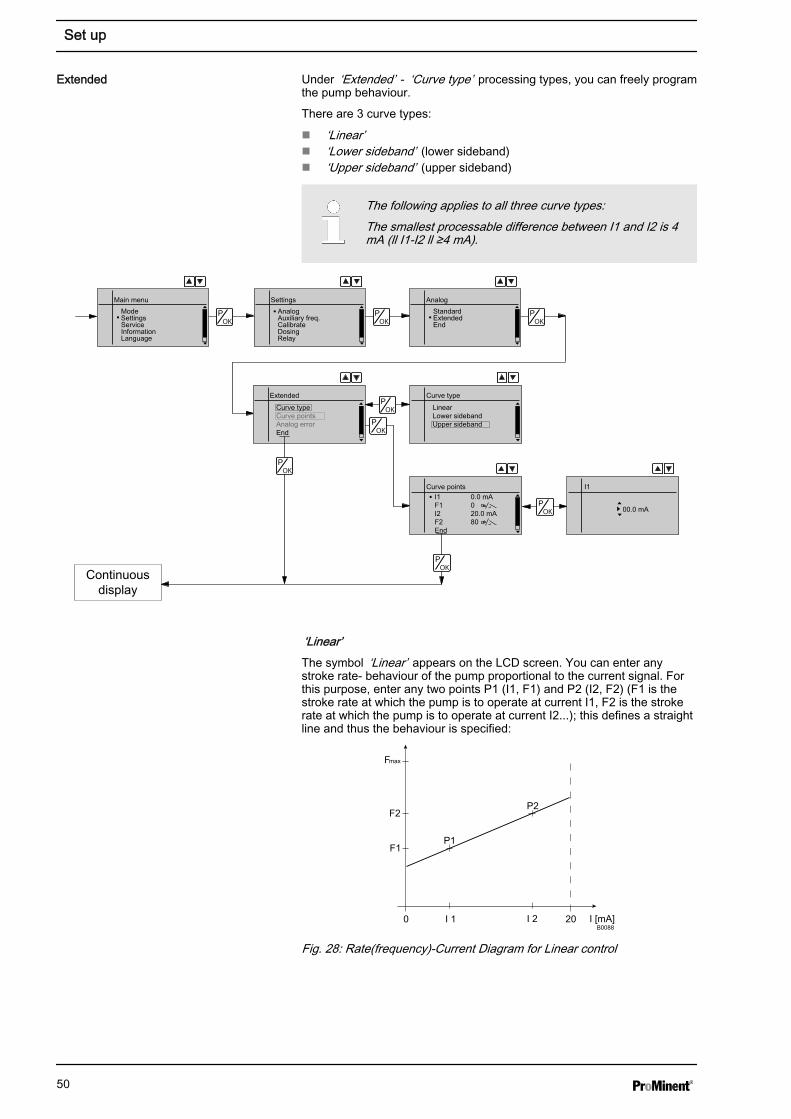
Under ‘Extended’ - ‘Curve type’ processing types, you can freely programthe pump behaviour.
There are 3 curve types:
n ‘Linear’n ‘Lower sideband’ (lower sideband)n ‘Upper sideband’ (upper sideband)
The following applies to all three curve types:The smallest processable difference between I1 and I2 is 4mA (ll I1-I2 ll ≥4 mA).
Extended
Curve typeCurve pointsAnalog errorEnd
Main menuModeSettingsServiceInformationLanguage
SettingsAnalogAuxiliary freq.CalibrateDosingRelay
AnalogStandardExtendedEnd
Curve type
LinearLower sidebandUpper sideband
Curve pointsI1 0.0 mAF1 0I2 20.0 mAF2 80End
I1
Continuousdisplay
00.0 mA
‘Linear’The symbol ‘Linear’ appears on the LCD screen. You can enter anystroke rate- behaviour of the pump proportional to the current signal. Forthis purpose, enter any two points P1 (I1, F1) and P2 (I2, F2) (F1 is thestroke rate at which the pump is to operate at current I1, F2 is the strokerate at which the pump is to operate at current I2...); this defines a straightline and thus the behaviour is specified:
I [mA]I 1 I 2
F1
F2
Fmax
0 20
P1
P2
B0088
Fig. 28: Rate(frequency)-Current Diagram for Linear control
Extended
Set up
50
Plot a diagram similar to the one above - with values for (I1,F1) and (I2, F2) – so that you can set the pump as desired!
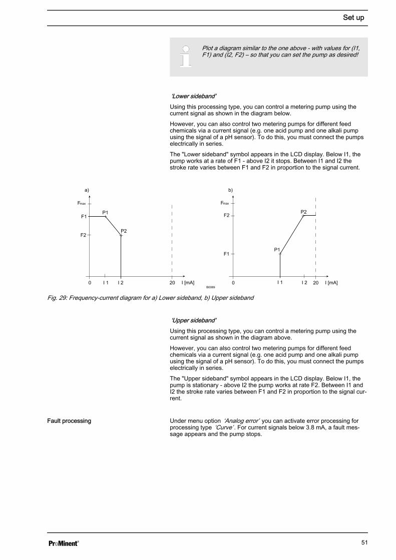
‘Lower sideband’Using this processing type, you can control a metering pump using thecurrent signal as shown in the diagram below.
However, you can also control two metering pumps for different feedchemicals via a current signal (e.g. one acid pump and one alkali pumpusing the signal of a pH sensor). To do this, you must connect the pumpselectrically in series.
The "Lower sideband" symbol appears in the LCD display. Below I1, thepump works at a rate of F1 - above I2 it stops. Between I1 and I2 thestroke rate varies between F1 and F2 in proportion to the signal current.
I [mA]I 1 I 2
F2
F1
0 20
a) b)
P1
P2
Fmax
B0089I [mA]I 1 I 2
F1
0 20
P1
P2 F2
Fmax
Fig. 29: Frequency-current diagram for a) Lower sideband, b) Upper sideband
‘Upper sideband’Using this processing type, you can control a metering pump using thecurrent signal as shown in the diagram above.
However, you can also control two metering pumps for different feedchemicals via a current signal (e.g. one acid pump and one alkali pumpusing the signal of a pH sensor). To do this, you must connect the pumpselectrically in series.
The "Upper sideband" symbol appears in the LCD display. Below I1, thepump is stationary - above I2 the pump works at rate F2. Between I1 andI2 the stroke rate varies between F1 and F2 in proportion to the signal cur‐rent.
Under menu option ‘Analog error’ you can activate error processing forprocessing type ‘Curve’ . For current signals below 3.8 mA, a fault mes‐sage appears and the pump stops.
Fault processing
Set up
51
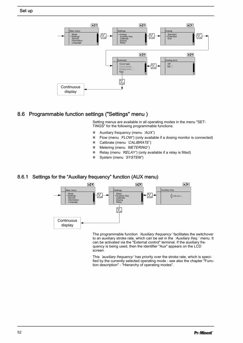
Extended
Curve typeCurve pointsAnalog errorEnd
Main menuModeSettingsServiceInformationLanguage
SettingsAnalogAuxiliary freq.CalibrateDosingRelay
AnalogStandardExtendedEnd
Analog error
OffOn
Continuousdisplay
8.6 Programmable function settings ("Settings" menu )Setting menus are available in all operating modes in the menu "SET‐TINGS" for the following programmable functions:
n Auxiliary frequency (menu ‘AUX’ )n Flow (menu ‘FLOW’ ) (only available if a dosing monitor is connected)n Calibrate (menu ‘CALIBRATE’ )n Metering (menu ‘METERING’ )n Relay (menu ‘RELAY’ ) (only available if a relay is fitted)n System (menu ‘SYSTEM’ )
8.6.1 Settings for the “Auxiliary frequency” function (AUX menu)
Continuousdisplay
Main menuModeSettingsServiceInformationLanguage
SettingsBatchAuxiliary freq.CalibrateDosingRelay
Auxiliary freq.
0 70
The programmable function ‘Auxiliary frequency’ facilitates the switchoverto an auxiliary stroke rate, which can be set in the ‘Auxiliary freq.’ menu. Itcan be activated via the "External control" terminal. If the auxiliary fre‐quency is being used, then the identifier "Aux" appears on the LCDscreen.
This ‘auxiliary frequency’ has priority over the stroke rate, which is speci‐fied by the currently selected operating mode - see also the chapter "Func‐tion description" - "Hierarchy of operating modes".
Set up
52
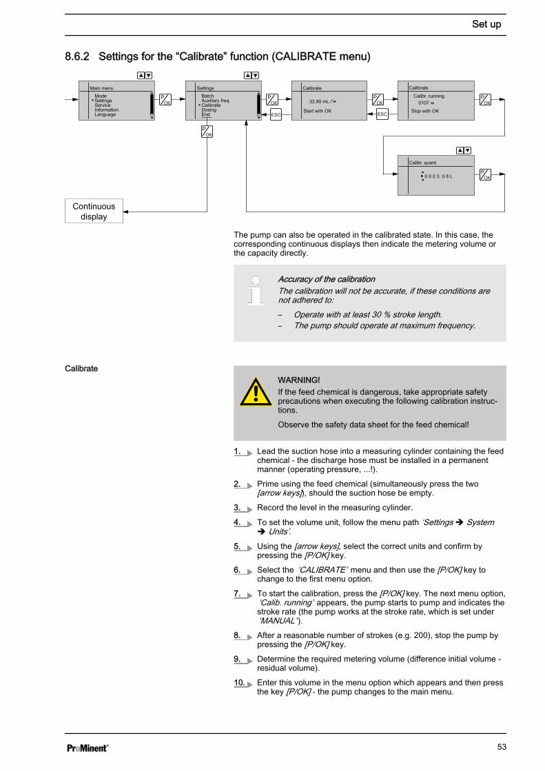
8.6.2 Settings for the “Calibrate” function (CALIBRATE menu)
Continuousdisplay
Calibrate
Calibr. runningMain menu
ModeSettingsServiceInformationLanguage
SettingsBatchAuxiliary freq.CalibrateDosingEnd
Calibrate
Start with OK
32.90 mL
Stop with OK
0107
Calibr. quant.
0 0 0 3. 0 8 L
The pump can also be operated in the calibrated state. In this case, thecorresponding continuous displays then indicate the metering volume orthe capacity directly.
Accuracy of the calibrationThe calibration will not be accurate, if these conditions arenot adhered to:– Operate with at least 30 % stroke length.– The pump should operate at maximum frequency.
WARNING!If the feed chemical is dangerous, take appropriate safetyprecautions when executing the following calibration instruc‐tions.
Observe the safety data sheet for the feed chemical!
1. Lead the suction hose into a measuring cylinder containing the feedchemical - the discharge hose must be installed in a permanentmanner (operating pressure, ...!).
2. Prime using the feed chemical (simultaneously press the two[arrow keys]), should the suction hose be empty.
3. Record the level in the measuring cylinder.
4. To set the volume unit, follow the menu path ‘Settings è Systemè Units’.
5. Using the [arrow keys], select the correct units and confirm bypressing the [P/OK] key.
6. Select the ‘CALIBRATE’ menu and then use the [P/OK] key tochange to the first menu option.
7. To start the calibration, press the [P/OK] key. The next menu option,‘Calib. running’ appears, the pump starts to pump and indicates thestroke rate (the pump works at the stroke rate, which is set under‘MANUAL’ ).
8. After a reasonable number of strokes (e.g. 200), stop the pump bypressing the [P/OK] key.
9. Determine the required metering volume (difference initial volume -residual volume).
10. Enter this volume in the menu option which appears and then pressthe key [P/OK] - the pump changes to the main menu.
Calibrate
Set up
53
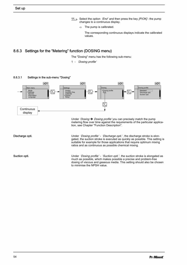
11. Select the option ‘End’ and then press the key [P/OK] - the pumpchanges to a continuous display.
ð The pump is calibrated.
The corresponding continuous displays indicate the calibratedvalues.
8.6.3 Settings for the “Metering” function (DOSING menu)The "Dosing" menu has the following sub-menu:
1 - ‘Dosing profile’
8.6.3.1 Settings in the sub-menu ″Dosing″
DosingMain menuModeSettingsServiceInformationLanguage
SettingsAnalogAuxiliary freq.CalibrateDosingRelay
Dosing profileEnd
Dosing profile
StandardDischarge opti.Suction opti.
Continuousdisplay
Under ‘Dosing è Dosing profile’ you can precisely match the pumpmetering flow over time against the requirements of the particular applica‐tion, see Chapter "Function Description".
Under ‘Dosing profile’ - ‘Discharge opti.’ , the discharge stroke is elon‐gated, the suction stroke is executed as quickly as possible. This setting issuitable for example for those applications that require optimum mixingratios and as continuous as possible chemical mixing.
Under ‘Dosing profile’ - ‘Suction opti.’ , the suction stroke is elongated asmuch as possible, which makes possible a precise and problem-freedosing of viscous and gaseous media. This setting should also be chosento minimise the NPSH value.
Discharge opti.
Suction opti.
Set up
54
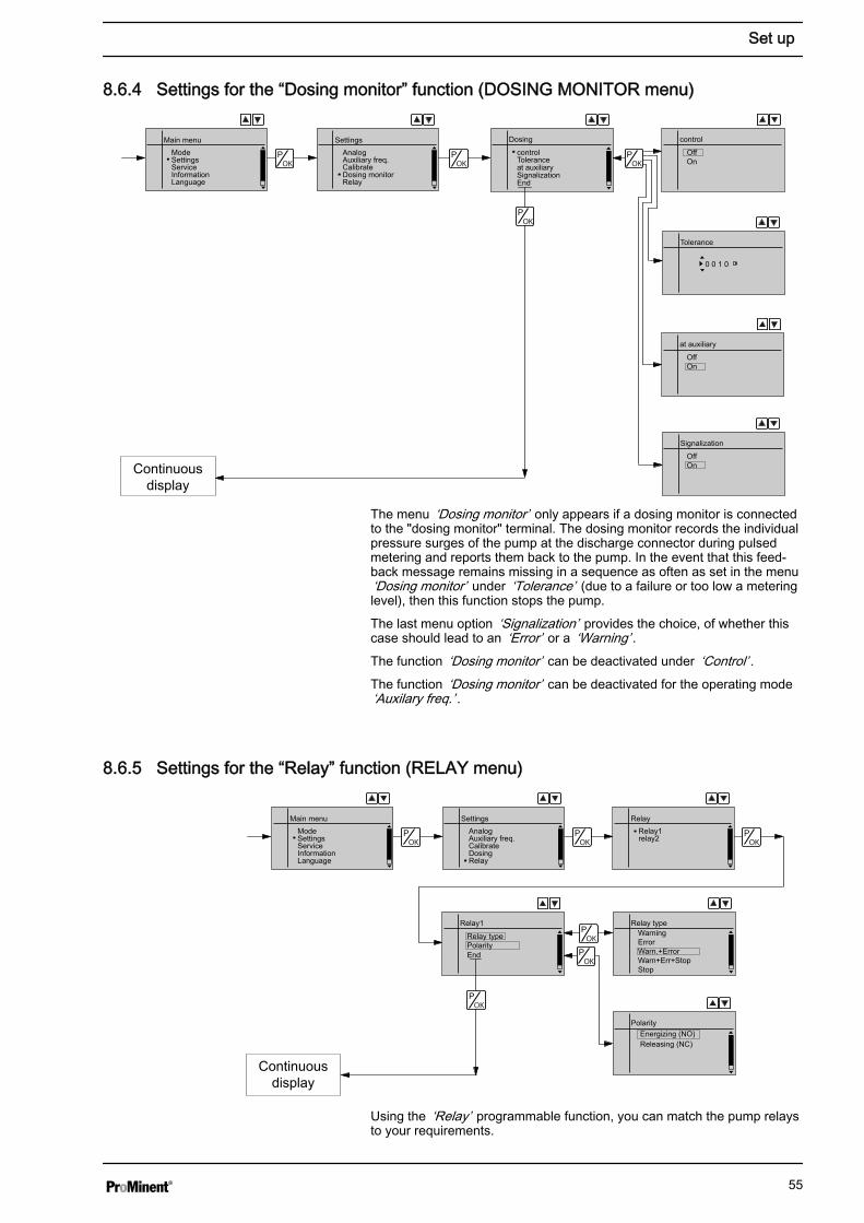
8.6.4 Settings for the “Dosing monitor” function (DOSING MONITOR menu)
DosingMain menuModeSettingsServiceInformationLanguage
SettingsAnalogAuxiliary freq.CalibrateDosing monitorRelay
controlToleranceat auxiliarySignalizationEnd
control
OffOn
Continuousdisplay
Tolerance
0 0 1 0
Signalization
at auxiliary
OffOn
OffOn
The menu ‘Dosing monitor’ only appears if a dosing monitor is connectedto the "dosing monitor" terminal. The dosing monitor records the individualpressure surges of the pump at the discharge connector during pulsedmetering and reports them back to the pump. In the event that this feed‐back message remains missing in a sequence as often as set in the menu‘Dosing monitor’ under ‘Tolerance’ (due to a failure or too low a meteringlevel), then this function stops the pump.
The last menu option ‘Signalization’ provides the choice, of whether thiscase should lead to an ‘Error’ or a ‘Warning’ .The function ‘Dosing monitor’ can be deactivated under ‘Control’ .The function ‘Dosing monitor’ can be deactivated for the operating mode‘Auxilary freq.’ .
8.6.5 Settings for the “Relay” function (RELAY menu)
Relay1
Relay typePolarityEnd
Main menuModeSettingsServiceInformationLanguage
SettingsAnalogAuxiliary freq.CalibrateDosingRelay
RelayRelay1relay2
Relay typeWarningErrorWarn.+ErrorWarn+Err+StopStop
PolarityEnergizing (NO) Releasing (NC)
Continuous
display
Using the ‘Relay’ programmable function, you can match the pump relaysto your requirements.
Set up
55
You can reprogram the relays using the ‘Relay’ function in an almostunlimited way.
You can set whether the respective relay is to switch due to a warningalert, a fault alert, a pump stroke or to a triggering event of the timer:
Selectable behaviour types
Setting in the ‘Relay’ menu Effect
Warning The relay switches upon a warning alert (yellow LED*).
Error The relay switches upon a fault alert (red LED*).
Warn.+Error The relay switches upon a warning alert (yellow LED*) or a fault alert (red LED*).
Warn+Err+Stop The relay switches upon a warning alert (yellow LED*) or a fault alert (red LED*)or a stop (key [STOP/START] or pause or bus command).
Stop The relay switches upon a stop (key [STOP/START] or pause or command froman optional module).
Pacing relay The relay switches every stroke.
Option The relay has the option of which module was plugged in (e.g. timer).
* see "Troubleshooting" chapter
You can also indicate how the respective relay should behave as soon asit switches. You can change this via the setting ‘ENERGIZING (NO)’ /‘RELEASING (NC).’
The setting option for the ‘Relay’ function only exists if arelay is present.
Allocations for the relay combinations
Display text "Relay 1" "Relay 2"
(Mechanical relay) Semiconductor relay)
Warning Warning relay Warning relay
Error Fault indicating relay Fault indicating relay
Warn.+Error Warning and fault indicating relay Warning and fault indicating relay
Warn.+Error+Stop Warning, fault indicating and cut-offrelay
Warning, fault indicating and cut-offrelay
Stop Cut-off relay Cut-off relay
Pacing relay - Pacing relay
Set up
56

8.6.6 Settings for the “Analog output” function (ANALOG OUTPUT menu)
Analog output
RangeFunctionEnd
Main menuModeSettingsServiceInformationLanguage
SettingsAnalogAuxiliary freq.CalibrateDosingAnalog output
Range0..20mA4..20mA
FunctionStrokes / minCapacityCapacity at 20mA
Continuous
display
Using the "Analog output" programmable function, you can match thepump current output signal (optional) to your requirements.
The signal I of the current output signal one of the three following varia‐bles:
n Strokes / minn Capacity (= current, calculated capacity)n Capacity at 20 mA (= capacity, value adjustable at 20 mA)
In the "Stop" or "Pause" states (either because of a fault or operation) or"Pause" the current output transmits a current of 4 mA or 0 mA.
The signal for the current, calculated capacity is calculated by the pumpaccording to the following formula (here for the range 4...20 mA):I(4...20) = 16 x (f/fmax) x (L/100) + 4with
l - Output current in mA
f - Stroke rate in strokes/min
L - Stroke length in %
fmax - Maximum stroke rate in strokes/min
In the ‘Contact’ and ‘Batch’ operating modes, f is the stroke rate which isset in the "Stroke rate" continuous display.
8.6.7 Settings for the “Diaphragm break” function (DIAPHRAGM BREAK menu)
Continuousdisplay
Main menuModeSettingsServiceInformationLanguage
SettingsDosing monitorRelayDiaphragm breakSystemEnd
Diaphragm break
ErrorWarningInactive
Using the "Diaphragm break" programmable function, you can match thebehaviour under fault conditions of the pump to your requirements, pro‐vided an electrical membrane rupture sensor is connected.
There is a choice, of whether a membrane rupture should lead to an‘Error’ or a ‘Warning’ . If ‘Inactive’ is set, the pump does not react to adiaphragm rupture, however the symbol dia indicates that an electricalmembrane rupture sensor is connected.
Set up
57
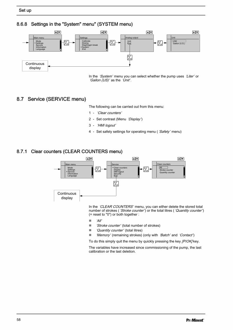
8.6.8 Settings in the "System" menu" (SYSTEM menu)
Analog output
UnitEnd
Main menuModeSettingsServiceInformationLanguage
SettingsCalibrateDosingDiaphragm breakSystemEnd
UnitLiter Gallon (U.S.)
Continuousdisplay
In the ‘System’ menu you can select whether the pump uses ‘Liter’ or‘Gallon (US)’ as the ‘Unit’ .
8.7 Service (SERVICE menu)The following can be carried out from this menu:
1 - ‘Clear counters’2 - Set contrast (Menu ‘Display’ )3 - ‘HMI logout’4 - Set safety settings for operating menu ( ‘Safety’ menu)
8.7.1 Clear counters (CLEAR COUNTERS menu)
Continuousdisplay
Main menuModeSettingsServiceInformationLanguage
ServiceClear countersDisplayHMI logoutSecurityEnd
Clear countersAllStroke counterQuantity counter
In the ‘CLEAR COUNTERS’ menu, you can either delete the stored totalnumber of strokes ( ‘Stroke counter’ ) or the total litres ( ‘Quantity counter’ )(= reset to "0") or both together :
n ‘All’n ‘Stroke counter’ (total number of strokes)n ‘Quantity counter’ (total litres)n ‘Memory’ (remaining strokes) (only with ‘Batch’ and ‘Contact’ )To do this simply quit the menu by quickly pressing the key [P/OK] key.
The variables have increased since commissioning of the pump, the lastcalibration or the last deletion.
Set up
58
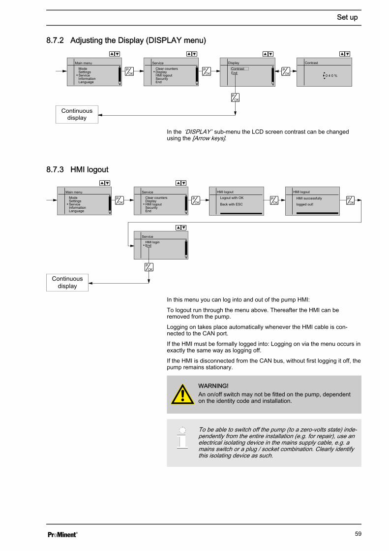
8.7.2 Adjusting the Display (DISPLAY menu)
Display
ContrastEnd
Main menuModeSettingsServiceInformationLanguage
ServiceClear countersDisplayHMI logoutSecurityEnd
Contrast
0 4 0 %
Continuousdisplay
In the ‘DISPLAY’ sub-menu the LCD screen contrast can be changedusing the [Arrow keys].
8.7.3 HMI logout
HMI logout
Logout with OK
Back with ESC
Main menuModeSettingsServiceInformationLanguage
ServiceClear countersDisplayHMI logoutSecurityEnd
ServiceHMI loginEnd
HMI logout
HMI successfully
logged out!
Continuousdisplay
In this menu you can log into and out of the pump HMI:
To logout run through the menu above. Thereafter the HMI can beremoved from the pump.
Logging on takes place automatically whenever the HMI cable is con‐nected to the CAN port.
If the HMI must be formally logged into: Logging on via the menu occurs inexactly the same way as logging off.
If the HMI is disconnected from the CAN bus, without first logging it off, thepump remains stationary.
WARNING!An on/off switch may not be fitted on the pump, dependenton the identity code and installation.
To be able to switch off the pump (to a zero-volts state) inde‐pendently from the entire installation (e.g. for repair), use anelectrical isolating device in the mains supply cable, e.g. amains switch or a plug / socket combination. Clearly identifythis isolating device as such.
Set up
59
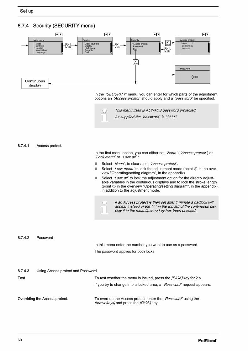
8.7.4 Security (SECURITY menu)
Security
Access protect.PasswordEnd
Main menuModeSettingsServiceInformationLanguage
ServiceClear countersDisplayHMI logoutSecurityEnd
Access protect.noneLock menuLock all
Password
2683 Continuous
display
In the ‘SECURITY’ menu, you can enter for which parts of the adjustmentoptions an ‘Access protect’ should apply and a ‘password’ be specified.
This menu itself is ALWAYS password protected.As supplied the ‘password’ is "1111".
8.7.4.1 Access protect.
In the first menu option, you can either set ‘None’ ( ‘Access protect’ ) or‘Lock menu’ or ‘Lock all’ :n Select ‘None’ , to clear a set ‘Access protect’ .n Select ‘Lock menu’ to lock the adjustment mode (point ① in the over‐
view "Operating/setting diagram", in the appendix).n Select ‘Lock all’ to lock the adjustment option for the directly adjust‐
able variables in the continuous displays and to lock the stroke length(point ② in the overview "Operating/setting diagram", in the appendix),in addition to the adjustment mode.
If an Access protect is then set after 1 minute a padlock willappear instead of the " i " in the top left of the continuous dis‐play if in the meantime no key has been pressed.
8.7.4.2 Password
In this menu enter the number you want to use as a password.
The password applies for both locks.
8.7.4.3 Using Access protect and Password
To test whether the menu is locked, press the [P/OK] key for 2 s.
If you try to change into a locked area, a ‘Password’ request appears.
To override the Access protect, enter the ‘Password’ using the[arrow keys] and press the [P/OK] key.
Test
Overriding the Access protect.
Set up
60
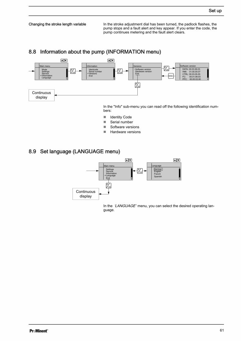
In the stroke adjustment dial has been turned, the padlock flashes, thepump stops and a fault alert and key appear. If you enter the code, thepump continues metering and the fault alert clears.
8.8 Information about the pump (INFORMATION menu)
Continuousdisplay
Software versionDATA: 00.03.06.03HMI: 01.00.00.07CTRL: 00.03.05.05FC: 00.01.08.03PFC: 00.00.03.00
Main menuModeSettingsServiceInformationLanguage
InformationIdentcodeSerial numberVersionsEnd
VersionsSoftware versionHardware versionEnd
ESC
In the "Info" sub-menu you can read off the following identification num‐bers:
n Identity Coden Serial numbern Software versionsn Hardware versions
8.9 Set language (LANGUAGE menu)
LanguageMain menuSettingsServiceInformationLanguageEnd
GermanEnglishFrenchSpanish
Continuousdisplay
In the ‘LANGUAGE’ menu, you can select the desired operating lan‐guage.
Changing the stroke length variable
Set up
61
9 Start up
WARNING!Fire hazard with flammable mediaOnly with combustible media: These may start to burn whencombined with oxygen.
– During filling and draining of the liquid end, an expertmust ensure that feed chemical does not come into con‐tact with oxygen.
CAUTION!Feed chemical could escape– Check suction and discharge lines and liquid end with
valves for leak-tightness and tighten if necessary.– Check whether the necessary flushing pipes or bleed
lines have been connected.
CAUTION!Prior to commissioning, check that the pump and corre‐sponding ancillary equipment is connected in compliancewith the regulations.
CAUTION!When using pumps with speed control, observe the instruc‐tions in the frequency converter operating instructions.
CAUTION!Danger resulting from unnoticed diaphragm ruptureIf the pump has been ordered with an electric diaphragm rup‐ture sensor, it still has to be installed.
– Screw the enclosed diaphragm rupture sensor into theliquid end.
CAUTION!Warning of unnoticed diaphragm ruptureOnly above approximately 2 bar system back pressure is asignal generated upon a diaphragm rupture.
– Only rely on the diaphragm rupture sensor at back pres‐sures greater than 2 bar.
When commissioning the unit, check whether the drive motor is rotatingcorrectly - check this against the arrow on the motor housing or the dia‐gram in the chapter entitled "Electrical Installation."
Safety notes
Diaphragm rupture sensor
Checking the direction of rotation
Start up
62
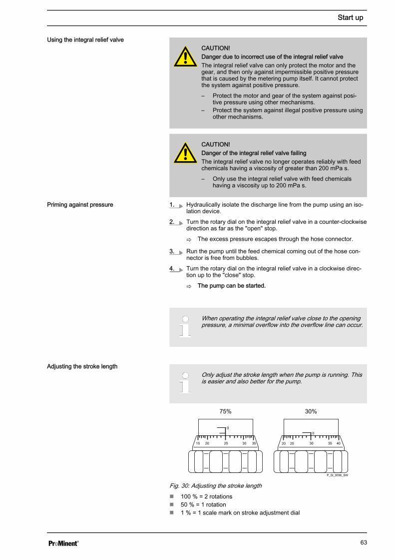
CAUTION!Danger due to incorrect use of the integral relief valveThe integral relief valve can only protect the motor and thegear, and then only against impermissible positive pressurethat is caused by the metering pump itself. It cannot protectthe system against positive pressure.
– Protect the motor and gear of the system against posi‐tive pressure using other mechanisms.
– Protect the system against illegal positive pressure usingother mechanisms.
CAUTION!Danger of the integral relief valve failingThe integral relief valve no longer operates reliably with feedchemicals having a viscosity of greater than 200 mPa s.
– Only use the integral relief valve with feed chemicalshaving a viscosity up to 200 mPa s.
1. Hydraulically isolate the discharge line from the pump using an iso‐lation device.
2. Turn the rotary dial on the integral relief valve in a counter-clockwisedirection as far as the "open" stop.
ð The excess pressure escapes through the hose connector.
3. Run the pump until the feed chemical coming out of the hose con‐nector is free from bubbles.
4. Turn the rotary dial on the integral relief valve in a clockwise direc‐tion up to the "close" stop.
ð The pump can be started.
When operating the integral relief valve close to the openingpressure, a minimal overflow into the overflow line can occur.
Only adjust the stroke length when the pump is running. Thisis easier and also better for the pump.
15 25 3020 35
75%
20 25 30
00
35 40
30%
P_SI_0096_SW
Fig. 30: Adjusting the stroke lengthn 100 % = 2 rotationsn 50 % = 1 rotationn 1 % = 1 scale mark on stroke adjustment dial
Using the integral relief valve
Priming against pressure
Adjusting the stroke length
Start up
63
10 Operation
WARNING!Fire hazard with flammable mediaOnly with combustible media: These may start to burn whencombined with oxygen.
– During filling and draining of the liquid end, an expertmust ensure that feed chemical does not come into con‐tact with oxygen.
WARNING!Danger of electric shockIncompletely installed electrical options can allow moistureinto the inside of the housing.
– Knock-out openings in the pump housing must beequipped with matching modules or be sealed in a leak-tight manner.
WARNING!Danger of electric shockA mains voltage may exist inside the pump housing.
– If the pump housing has been damaged, you must dis‐connect it from the mains immediately. It may only bereturned to service after an authorised repair.
CAUTION!Do not over extend the spiral cable of the HMI.
It may only be extended to 0.5 m.
This chapter describes all the operating options available to you if thepump is displaying a continuous display - in the top left of the display thereis an " i ".
– For supplementary information, see the overviews "Con‐trol elements and key functions" in the chapter "Deviceoverview and control elements" and "Operating/settingdiagram" in the appendix.
– Also take note of the overview "Continuous displays" inthe appendix. It shows which continuous displays areavailable in which operating mode and which variablesare directly changeable in the relevant continuous dis‐play.
10.1 ManualPersonnel: n Instructed personnel
The stroke length is adjusted by the stroke length adjustment knob withina range of 0 ... 100 %. A stroke length of between 30 ... 100 %) is recom‐mended to achieve the specified reproducibility.
Adjusting the stroke length
Operation
64
The following operating options are available via the keys - see the nextfigure:
Stop the pump: Press the [STOP/START] key.
Start the pump: press the [STOP/START] key again.
In ‘Batch’ operating mode: briefly press key [P/OK].
In continuous display if you keep the [P/OK] key pressed for 2 s, the pumpswitches into adjustment mode - see "Adjustment" chapter.
If under ‘Service è Security è Access protect’ the selection ‘Lock menu’or ‘Lock all’ was set, then after pressing the key [P/OK] the ‘Password’must first be entered.
Each time you press the [i/>] key, you can see a different continuous dis‐play possibly mixed with error messages. The number of continuous dis‐plays depends on the identity code, the selected operating mode and theconnected additional devices.
The same applies for auxiliary displays, which are accessed a longersingle press of the key [i/>].
To change a variable (see below) directly in the corresponding continuousdisplay, press one of the [arrow keys].If under ‘Service è Security è Access protect’ the selection ‘Lock all’was set, then after pressing the key [P/OK] the ‘Password’ must first beentered.
The directly changeable variables are in detail:
In operating modes ‘Manual’ , ‘Contact’ and ‘Batch’ :You can change the stroke rate in the "Stroke rate" continuous display.
To change a precisely previously set feed rate (possiblyspecified in litres), there is an option of changing it via thestroke rate. As the stroke rate is digitally processed, there isno tolerance.By contrast, changing via the stroke length interferes with themechanical tolerance.
You can change the capacity once the pump has been calibrated in the"Capacity" continuous display.
To change a precisely previously set feed rate (possiblyspecified in litres), there is an option of changing it via thecapacity. As the capacity is digitally processed, there is notolerance.By contrast, changing via the stroke length interferes with themechanical tolerance.
Only in ‘Batch’ mode: The factor is the number of strokes which are trig‐gered upon an external pulse or pressing of key [P/OK].
Stopping/starting the pump
Starting batch
Changing to adjustment mode
Checking adjustable values
Change directly changeable variables
Stroke rate
Capacity
Factor
Operation
65
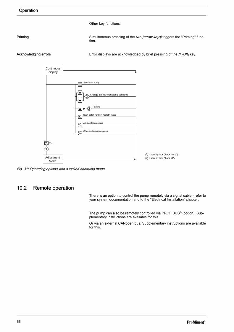
Other key functions:
Simultaneous pressing of the two [arrow keys] triggers the "Priming" func‐tion.
Error displays are acknowledged by brief pressing of the [P/OK] key.
2 s
2
2
2
11
AdjustmentMode
Continuousdisplay
Stop/start pump
Change directly changeable variables
= security lock ("Lock menu")= security lock ("Lock all")
Priming
Start batch (only in "Batch" mode)
Acknowledge errors
Check adjustable values
Fig. 31: Operating options with a locked operating menu
10.2 Remote operationThere is an option to control the pump remotely via a signal cable - refer toyour system documentation and to the "Electrical Installation" chapter.
The pump can also be remotely controlled via PROFIBUS® (option). Sup‐plementary instructions are available for this.
Or via an external CANopen bus. Supplementary instructions are availablefor this.
Priming
Acknowledging errors
Operation
66
11 Maintenance
WARNING!Fire hazard with flammable mediaOnly with combustible media: These may start to burn whencombined with oxygen.
– During filling and draining of the liquid end, an expertmust ensure that feed chemical does not come into con‐tact with oxygen.
WARNING!It is mandatory that you read the safety information andspecifications in the "Storage, Transport and Unpacking"chapter prior to shipping the pump.
CAUTION!Warning of feed chemical spraying aroundFeed chemical can spray out of the hydraulic components ifthey are manipulated or opened due to pressure in the liquidend and adjacent parts of the system.
– Disconnect the pump from the mains power supply andensure that it cannot be switched on again by unauthor‐ised persons.
– Depressurise the system before commencing any workon hydraulic parts.
WARNING!Warning of dangerous or unknown feed chemicalShould a dangerous or unknown feed chemical be used: Itmay escape from the hydraulic components when workingon the pump.
– Take appropriate protective measures before working onthe pump (e.g. safety glasses, safety gloves, ...).Observe the safety data sheet for the feed chemical.
– Drain and flush the liquid end before working on thepump.
WARNING!Danger of an electric shockWhen working on the motor or electrical auxiliary equipment,there is a danger of an electric shock.
– Before working on the motor, take note of the safetyinstructions in its operating instructions!
– Should external fans, servomotors or other auxiliaryequipment be installed, these should also be discon‐nected and checked that they are voltage free.
Safety notes
Maintenance
67
Third party spare parts for the pumps may lead to problemswhen pumping.– Use only original spare parts.– Use the correct spare parts kits. In case of doubt, refer
to the exploded views and ordering information in theappendix.
Interval Maintenance work Personnel
Quarterly* n Check that the metering lines are fixed firmly to the liquid end.n Check that the suction valve and discharge valve are fitted tightly.n Check that the dosing head screws are tight.n Check the condition of the metering diaphragm - see Ä ‘Check the condi‐
tion of the metering diaphragm’ on page 68.n Check that the flow is correct: Allow the pump to prime briefly.n Check that the electrical connections are intact.
Technical personnel
* Under normal loading (approx. 30 % of continuous operation).
Under heavy loading (e.g. continuous operation): shorter intervals.
The diaphragm is a wearing part, the service life of which is dependentupon the following parameters:
n System back pressuren Operating temperaturen Feed chemical properties
When using abrasive feed chemicals, the diaphragm service life isreduced. In such cases, more frequent checking of the diaphragm is rec‐ommended.
Data Value Unit
Tightening torques for dosing headscrews:
4.5 ... 5.0 Nm
WARNING!Warning of eye injuriesWhen opening the relief valve, a spring under high tensioncan jump out.
– Wear protective glasses.
Standard liquid ends:
Check the condition of the metering dia‐phragm
Tightening torques
Liquid ends with integral relief valve
Maintenance
68
12 Repairs
WARNING!Fire hazard with flammable mediaOnly with combustible media: These may start to burn whencombined with oxygen.
– During filling and draining of the liquid end, an expertmust ensure that feed chemical does not come into con‐tact with oxygen.
WARNING!It is mandatory that you read the safety information andspecifications in the "Storage, Transport and Unpacking"chapter prior to shipping the pump.
CAUTION!Warning of feed chemical spraying aroundFeed chemical can spray out of the hydraulic components ifthey are manipulated or opened due to pressure in the liquidend and adjacent parts of the system.
– Disconnect the pump from the mains power supply andensure that it cannot be switched on again by unauthor‐ised persons.
– Depressurise the system before commencing any workon hydraulic parts.
WARNING!Warning of dangerous or unknown feed chemicalShould a dangerous or unknown feed chemical be used: Itmay escape from the hydraulic components when workingon the pump.
– Take appropriate protective measures before working onthe pump (e.g. safety glasses, safety gloves, ...).Observe the safety data sheet for the feed chemical.
– Drain and flush the liquid end before working on thepump.
12.1 Cleaning valves
Unsuitable spare parts for the valves may lead to problemsfor the pumps.– Only use new components that are especially adapted to
fit your valve (both in terms of shape and chemicalresistance).
– Use the correct spare parts kits. In case of doubt, referto the exploded views and ordering information in theappendix.
Safety notes
Repairs
69
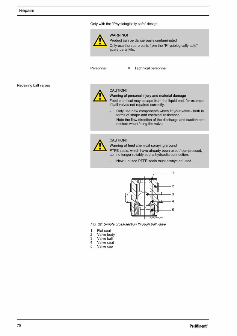
Only with the "Physiologically safe" design:
WARNING!Product can be dangerously contaminatedOnly use the spare parts from the "Physiologically safe"spare parts kits.
Personnel: n Technical personnel
CAUTION!Warning of personal injury and material damageFeed chemical may escape from the liquid end, for example,if ball valves not repaired correctly.
– Only use new components which fit your valve - both interms of shape and chemical resistance!
– Note the flow direction of the discharge and suction con‐nectors when fitting the valve.
CAUTION!Warning of feed chemical spraying aroundPTFE seals, which have already been used / compressed,can no longer reliably seal a hydraulic connection.
– New, unused PTFE seals must always be used.
1
2
3
4
5
P_SI_0013_SW
Fig. 32: Simple cross-section through ball valve1 Flat seal2 Valve body3 Valve ball4 Valve seat5 Valve cap
Repairing ball valves
Repairs
70
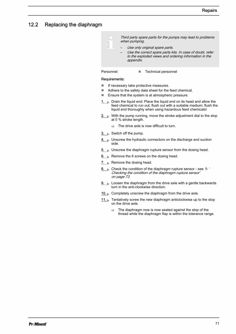
12.2 Replacing the diaphragm
Third party spare parts for the pumps may lead to problemswhen pumping.– Use only original spare parts.– Use the correct spare parts kits. In case of doubt, refer
to the exploded views and ordering information in theappendix.
Personnel: n Technical personnel
Requirements:
n If necessary take protective measures.n Adhere to the safety data sheet for the feed chemical.n Ensure that the system is at atmospheric pressure.
1. Drain the liquid end: Place the liquid end on its head and allow thefeed chemical to run out; flush out with a suitable medium; flush theliquid end thoroughly when using hazardous feed chemicals!
2. With the pump running, move the stroke adjustment dial to the stopat 0 % stroke length.
ð The drive axle is now difficult to turn.
3. Switch off the pump.
4. Unscrew the hydraulic connectors on the discharge and suctionside.
5. Unscrew the diaphragm rupture sensor from the dosing head.
6. Remove the 6 screws on the dosing head.
7. Remove the dosing head.
8. Check the condition of the diaphragm rupture sensor - see Ä ‘Checking the condition of the diaphragm rupture sensor’ on page 73.
9. Loosen the diaphragm from the drive axle with a gentle backwardsturn in the anti-clockwise direction.
10. Completely unscrew the diaphragm from the drive axle.
11. Tentatively screw the new diaphragm anticlockwise up to the stopon the drive axle.
ð The diaphragm now is now seated against the stop of thethread while the diaphragm flap is within the tolerance range.
Repairs
71
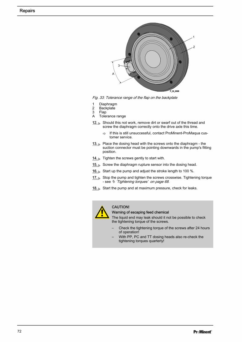
P_SI_0029
2
3
A
1
Fig. 33: Tolerance range of the flap on the backplate1 Diaphragm2 Backplate3 FlapA Tolerance range
12. Should this not work, remove dirt or swarf out of the thread andscrew the diaphragm correctly onto the drive axle this time.
ð If this is still unsuccessful, contact ProMinent-ProMaqua cus‐tomer service.
13. Place the dosing head with the screws onto the diaphragm - thesuction connector must be pointing downwards in the pump's fittingposition.
14. Tighten the screws gently to start with.
15. Screw the diaphragm rupture sensor into the dosing head.
16. Start up the pump and adjust the stroke length to 100 %.
17. Stop the pump and tighten the screws crosswise. Tightening torque- see Ä ‘Tightening torques’ on page 68.
18. Start the pump and at maximum pressure, check for leaks.
CAUTION!Warning of escaping feed chemicalThe liquid end may leak should it not be possible to checkthe tightening torque of the screws.
– Check the tightening torque of the screws after 24 hoursof operation!
– With PP, PC and TT dosing heads also re-check thetightening torques quarterly!
Repairs
72
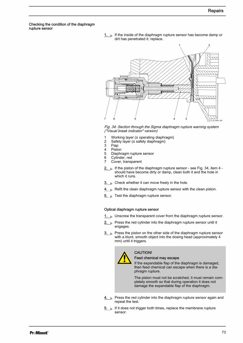
1. If the inside of the diaphragm rupture sensor has become damp ordirt has penetrated it: replace.
7 6 5 4 3
21
P_SI_0020_SW
Fig. 34: Section through the Sigma diaphragm rupture warning system("Visual break indicator" version)1 Working layer (≙ operating diaphragm)2 Safety layer (≙ safety diaphragm)3 Flap4 Piston5 Diaphragm rupture sensor6 Cylinder, red7 Cover, transparent
2. If the piston of the diaphragm rupture sensor - see Fig. 34, item 4 -should have become dirty or damp, clean both it and the hole inwhich it runs.
3. Check whether it can move freely in the hole.
4. Refit the clean diaphragm rupture sensor with the clean piston.
5. Test the diaphragm rupture sensor.
Optical diaphragm rupture sensor
1. Unscrew the transparent cover from the diaphragm rupture sensor.
2. Press the red cylinder into the diaphragm rupture sensor until itengages.
3. Press the piston on the other side of the diaphragm rupture sensorwith a blunt, smooth object into the dosing head (approximately 4mm) until it triggers.
CAUTION!Feed chemical may escapeIf the expandable flap of the diaphragm is damaged,then feed chemical can escape when there is a dia‐phragm rupture.
The piston must not be scratched, it must remain com‐pletely smooth so that during operation it does notdamage the expandable flap of the diaphragm.
4. Press the red cylinder into the diaphragm rupture sensor again andrepeat the test.
5. If it does not trigger both times, replace the membrane rupturesensor.
Checking the condition of the diaphragmrupture sensor
Repairs
73
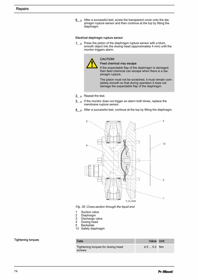
6. After a successful test, screw the transparent cover onto the dia‐phragm rupture sensor and then continue at the top by fitting thediaphragm.
Electrical diaphragm rupture sensor
1. Press the piston of the diaphragm rupture sensor with a blunt,smooth object into the dosing head (approximately 4 mm) until themonitor triggers alarm.
CAUTION!Feed chemical may escapeIf the expandable flap of the diaphragm is damaged,then feed chemical can escape when there is a dia‐phragm rupture.
The piston must not be scratched, it must remain com‐pletely smooth so that during operation it does notdamage the expandable flap of the diaphragm.
2. Repeat the test.
3. If the monitor does not trigger an alarm both times, replace themembrane rupture sensor.
4. After a successful test, continue at the top by fitting the diaphragm.
4
2
1
53
13
P_SI_0038
Fig. 35: Cross-section through the liquid end1 Suction valve2 Diaphragm3 Discharge valve4 Dosing head5 Backplate13 Safety diaphragm
Data Value Unit
Tightening torques for dosing headscrews:
4.5 ... 5.0 Nm
Tightening torques
Repairs
74
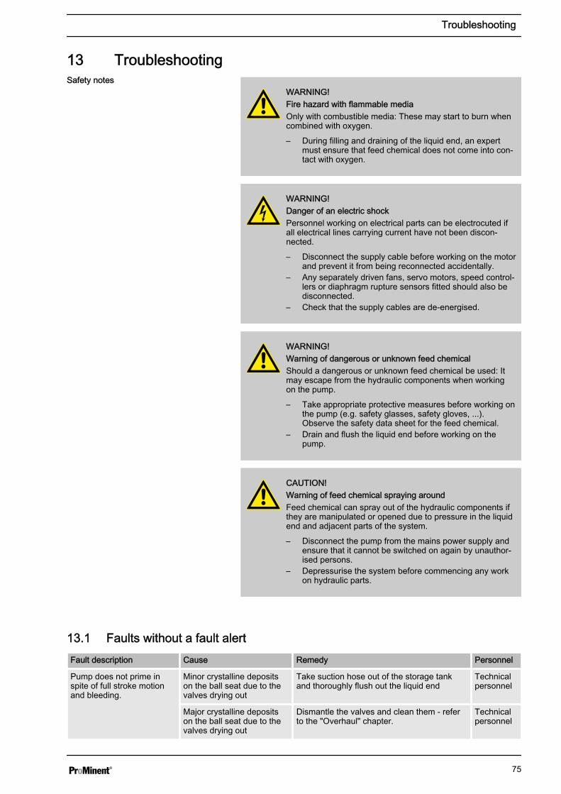
13 Troubleshooting
WARNING!Fire hazard with flammable mediaOnly with combustible media: These may start to burn whencombined with oxygen.
– During filling and draining of the liquid end, an expertmust ensure that feed chemical does not come into con‐tact with oxygen.
WARNING!Danger of an electric shockPersonnel working on electrical parts can be electrocuted ifall electrical lines carrying current have not been discon‐nected.
– Disconnect the supply cable before working on the motorand prevent it from being reconnected accidentally.
– Any separately driven fans, servo motors, speed control‐lers or diaphragm rupture sensors fitted should also bedisconnected.
– Check that the supply cables are de-energised.
WARNING!Warning of dangerous or unknown feed chemicalShould a dangerous or unknown feed chemical be used: Itmay escape from the hydraulic components when workingon the pump.
– Take appropriate protective measures before working onthe pump (e.g. safety glasses, safety gloves, ...).Observe the safety data sheet for the feed chemical.
– Drain and flush the liquid end before working on thepump.
CAUTION!Warning of feed chemical spraying aroundFeed chemical can spray out of the hydraulic components ifthey are manipulated or opened due to pressure in the liquidend and adjacent parts of the system.
– Disconnect the pump from the mains power supply andensure that it cannot be switched on again by unauthor‐ised persons.
– Depressurise the system before commencing any workon hydraulic parts.
13.1 Faults without a fault alertFault description Cause Remedy Personnel
Pump does not prime inspite of full stroke motionand bleeding.
Minor crystalline depositson the ball seat due to thevalves drying out
Take suction hose out of the storage tankand thoroughly flush out the liquid end
Technicalpersonnel
Major crystalline depositson the ball seat due to thevalves drying out
Dismantle the valves and clean them - referto the "Overhaul" chapter.
Technicalpersonnel
Safety notes
Troubleshooting
75
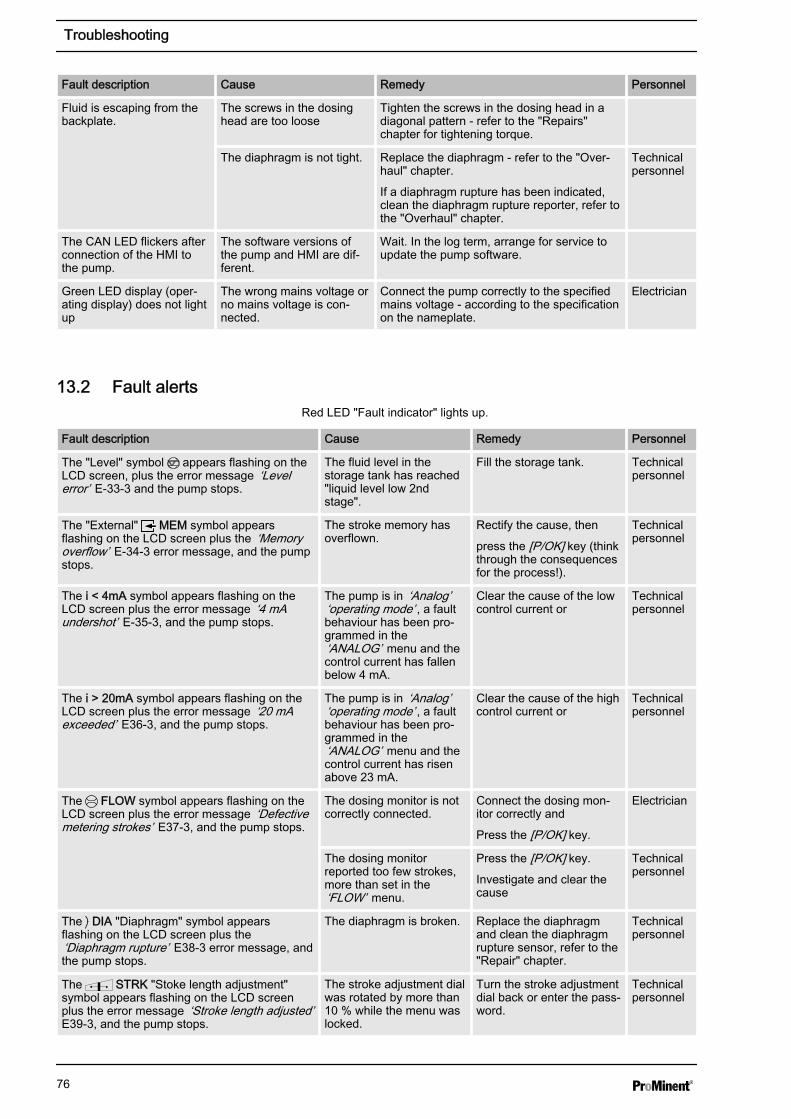
Fault description Cause Remedy Personnel
Fluid is escaping from thebackplate.
The screws in the dosinghead are too loose
Tighten the screws in the dosing head in adiagonal pattern - refer to the "Repairs"chapter for tightening torque.
The diaphragm is not tight. Replace the diaphragm - refer to the "Over‐haul" chapter.
If a diaphragm rupture has been indicated,clean the diaphragm rupture reporter, refer tothe "Overhaul" chapter.
Technicalpersonnel
The CAN LED flickers afterconnection of the HMI tothe pump.
The software versions ofthe pump and HMI are dif‐ferent.
Wait. In the log term, arrange for service toupdate the pump software.
Green LED display (oper‐ating display) does not lightup
The wrong mains voltage orno mains voltage is con‐nected.
Connect the pump correctly to the specifiedmains voltage - according to the specificationon the nameplate.
Electrician
13.2 Fault alertsRed LED "Fault indicator" lights up.
Fault description Cause Remedy Personnel
The "Level" symbol appears flashing on theLCD screen, plus the error message ‘Levelerror’ E-33-3 and the pump stops.
The fluid level in thestorage tank has reached"liquid level low 2ndstage".
Fill the storage tank. Technicalpersonnel
The "External" MEM symbol appearsflashing on the LCD screen plus the ‘Memoryoverflow’ E-34-3 error message, and the pumpstops.
The stroke memory hasoverflown.
Rectify the cause, then
press the [P/OK] key (thinkthrough the consequencesfor the process!).
Technicalpersonnel
The i < 4mA symbol appears flashing on theLCD screen plus the error message ‘4 mAundershot’ E-35-3, and the pump stops.
The pump is in ‘Analog’‘operating mode’ , a faultbehaviour has been pro‐grammed in the‘ANALOG’ menu and thecontrol current has fallenbelow 4 mA.
Clear the cause of the lowcontrol current or
Technicalpersonnel
The i > 20mA symbol appears flashing on theLCD screen plus the error message ‘20 mAexceeded’ E36-3, and the pump stops.
The pump is in ‘Analog’‘operating mode’ , a faultbehaviour has been pro‐grammed in the‘ANALOG’ menu and thecontrol current has risenabove 23 mA.
Clear the cause of the highcontrol current or
Technicalpersonnel
The FLOW symbol appears flashing on theLCD screen plus the error message ‘Defectivemetering strokes’ E37-3, and the pump stops.
The dosing monitor is notcorrectly connected.
Connect the dosing mon‐itor correctly and
Press the [P/OK] key.
Electrician
The dosing monitorreported too few strokes,more than set in the‘FLOW’ menu.
Press the [P/OK] key.
Investigate and clear thecause
Technicalpersonnel
The DIA "Diaphragm" symbol appearsflashing on the LCD screen plus the‘Diaphragm rupture’ E38-3 error message, andthe pump stops.
The diaphragm is broken. Replace the diaphragmand clean the diaphragmrupture sensor, refer to the"Repair" chapter.
Technicalpersonnel
The STRK "Stoke length adjustment"symbol appears flashing on the LCD screenplus the error message ‘Stroke length adjusted’E39-3, and the pump stops.
The stroke adjustment dialwas rotated by more than10 % while the menu waslocked.
Turn the stroke adjustmentdial back or enter the pass‐word.
Technicalpersonnel
Troubleshooting
76
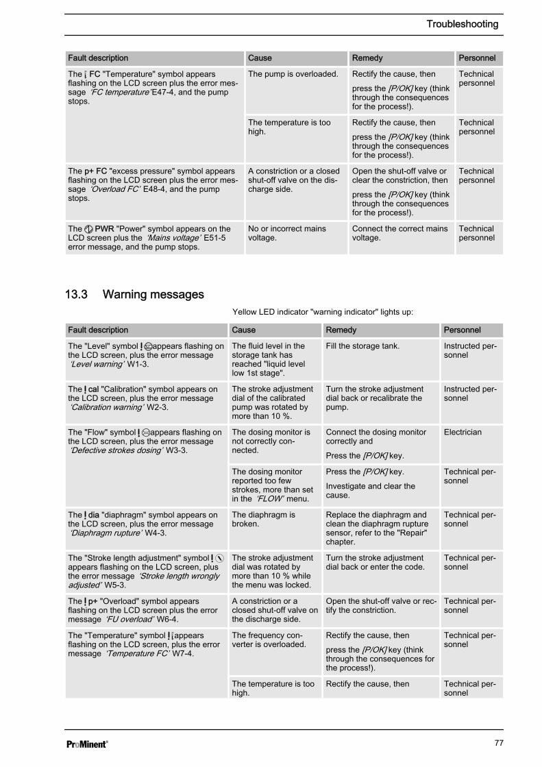
Fault description Cause Remedy Personnel
The C
F FC "Temperature" symbol appears
flashing on the LCD screen plus the error mes‐sage ‘FC temperature’ E47-4, and the pumpstops.
The pump is overloaded. Rectify the cause, then
press the [P/OK] key (thinkthrough the consequencesfor the process!).
Technicalpersonnel
The temperature is toohigh.
Rectify the cause, then
press the [P/OK] key (thinkthrough the consequencesfor the process!).
Technicalpersonnel
The p+ FC "excess pressure" symbol appearsflashing on the LCD screen plus the error mes‐sage ‘Overload FC’ E48-4, and the pumpstops.
A constriction or a closedshut-off valve on the dis‐charge side.
Open the shut-off valve orclear the constriction, then
press the [P/OK] key (thinkthrough the consequencesfor the process!).
Technicalpersonnel
The PWR "Power" symbol appears on theLCD screen plus the ‘Mains voltage’ E51-5error message, and the pump stops.
No or incorrect mainsvoltage.
Connect the correct mainsvoltage.
Technicalpersonnel
13.3 Warning messagesYellow LED indicator "warning indicator" lights up:
Fault description Cause Remedy Personnel
The "Level" symbol appears flashing onthe LCD screen, plus the error message‘Level warning’ W1-3.
The fluid level in thestorage tank hasreached "liquid levellow 1st stage".
Fill the storage tank. Instructed per‐sonnel
The cal "Calibration" symbol appears onthe LCD screen, plus the error message‘Calibration warning’ W2-3.
The stroke adjustmentdial of the calibratedpump was rotated bymore than 10 %.
Turn the stroke adjustmentdial back or recalibrate thepump.
Instructed per‐sonnel
The "Flow" symbol appears flashing onthe LCD screen, plus the error message‘Defective strokes dosing’ W3-3.
The dosing monitor isnot correctly con‐nected.
Connect the dosing monitorcorrectly and
Press the [P/OK] key.
Electrician
The dosing monitorreported too fewstrokes, more than setin the ‘FLOW’ menu.
Press the [P/OK] key.
Investigate and clear thecause.
Technical per‐sonnel
The dia "diaphragm" symbol appears onthe LCD screen, plus the error message‘Diaphragm rupture’ W4-3.
The diaphragm isbroken.
Replace the diaphragm andclean the diaphragm rupturesensor, refer to the "Repair"chapter.
Technical per‐sonnel
The "Stroke length adjustment" symbol appears flashing on the LCD screen, plusthe error message ‘Stroke length wronglyadjusted’ W5-3.
The stroke adjustmentdial was rotated bymore than 10 % whilethe menu was locked.
Turn the stroke adjustmentdial back or enter the code.
Technical per‐sonnel
The p+ "Overload" symbol appearsflashing on the LCD screen plus the errormessage ‘FU overload’ W6-4.
A constriction or aclosed shut-off valve onthe discharge side.
Open the shut-off valve or rec‐tify the constriction.
Technical per‐sonnel
The "Temperature" symbol C
Fappears
flashing on the LCD screen, plus the errormessage ‘Temperature FC’ W7-4.
The frequency con‐verter is overloaded.
Rectify the cause, then
press the [P/OK] key (thinkthrough the consequences forthe process!).
Technical per‐sonnel
The temperature is toohigh.
Rectify the cause, then Technical per‐sonnel
Troubleshooting
77
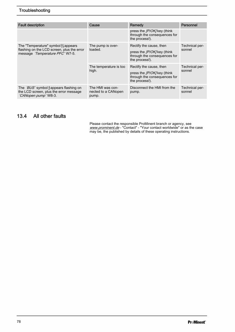
Fault description Cause Remedy Personnelpress the [P/OK] key (thinkthrough the consequences forthe process!).
The "Temperature" symbol C
Fappears
flashing on the LCD screen, plus the errormessage ‘Temperature PFC’ W7-5.
The pump is over‐loaded.
Rectify the cause, then
press the [P/OK] key (thinkthrough the consequences forthe process!).
Technical per‐sonnel
The temperature is toohigh.
Rectify the cause, then
press the [P/OK] key (thinkthrough the consequences forthe process!).
Technical per‐sonnel
The ‘BUS’ symbol appears flashing onthe LCD screen, plus the error message‘CANopen pump’ W8-3.
The HMI was con‐nected to a CANopenpump.
Disconnect the HMI from thepump.
Technical per‐sonnel
13.4 All other faultsPlease contact the responsible ProMinent branch or agency, seewww.prominent.de - "Contact" - "Your contact worldwide" or as the casemay be, the published by details of these operating instructions.
Troubleshooting
78
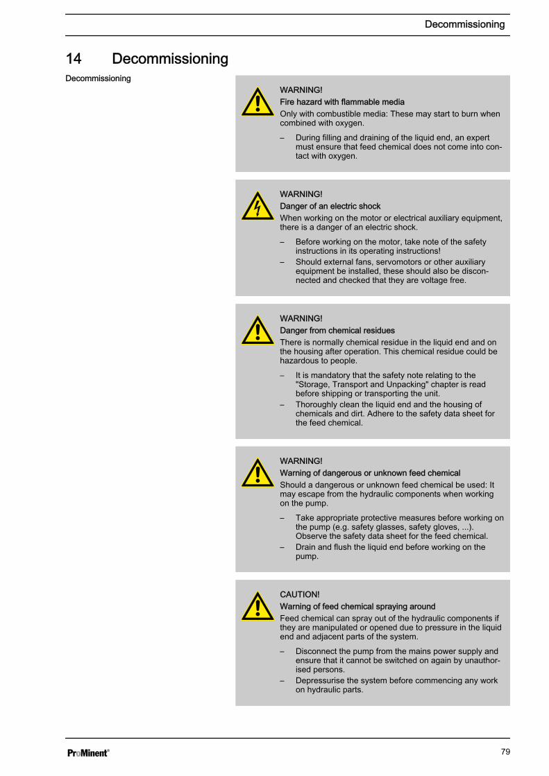
14 Decommissioning
WARNING!Fire hazard with flammable mediaOnly with combustible media: These may start to burn whencombined with oxygen.
– During filling and draining of the liquid end, an expertmust ensure that feed chemical does not come into con‐tact with oxygen.
WARNING!Danger of an electric shockWhen working on the motor or electrical auxiliary equipment,there is a danger of an electric shock.
– Before working on the motor, take note of the safetyinstructions in its operating instructions!
– Should external fans, servomotors or other auxiliaryequipment be installed, these should also be discon‐nected and checked that they are voltage free.
WARNING!Danger from chemical residuesThere is normally chemical residue in the liquid end and onthe housing after operation. This chemical residue could behazardous to people.
– It is mandatory that the safety note relating to the"Storage, Transport and Unpacking" chapter is readbefore shipping or transporting the unit.
– Thoroughly clean the liquid end and the housing ofchemicals and dirt. Adhere to the safety data sheet forthe feed chemical.
WARNING!Warning of dangerous or unknown feed chemicalShould a dangerous or unknown feed chemical be used: Itmay escape from the hydraulic components when workingon the pump.
– Take appropriate protective measures before working onthe pump (e.g. safety glasses, safety gloves, ...).Observe the safety data sheet for the feed chemical.
– Drain and flush the liquid end before working on thepump.
CAUTION!Warning of feed chemical spraying aroundFeed chemical can spray out of the hydraulic components ifthey are manipulated or opened due to pressure in the liquidend and adjacent parts of the system.
– Disconnect the pump from the mains power supply andensure that it cannot be switched on again by unauthor‐ised persons.
– Depressurise the system before commencing any workon hydraulic parts.
Decommissioning
Decommissioning
79
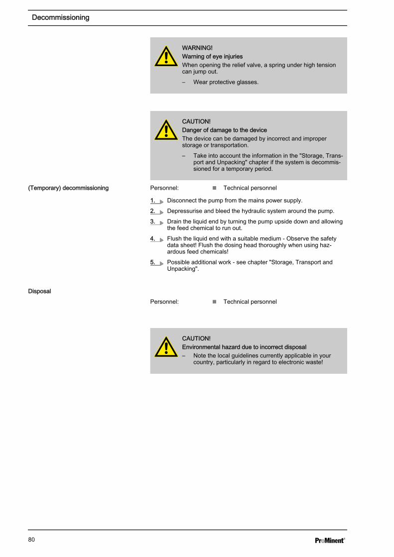
WARNING!Warning of eye injuriesWhen opening the relief valve, a spring under high tensioncan jump out.
– Wear protective glasses.
CAUTION!Danger of damage to the deviceThe device can be damaged by incorrect and improperstorage or transportation.
– Take into account the information in the "Storage, Trans‐port and Unpacking" chapter if the system is decommis‐sioned for a temporary period.
Personnel: n Technical personnel
1. Disconnect the pump from the mains power supply.
2. Depressurise and bleed the hydraulic system around the pump.
3. Drain the liquid end by turning the pump upside down and allowingthe feed chemical to run out.
4. Flush the liquid end with a suitable medium - Observe the safetydata sheet! Flush the dosing head thoroughly when using haz‐ardous feed chemicals!
5. Possible additional work - see chapter "Storage, Transport andUnpacking".
Personnel: n Technical personnel
CAUTION!Environmental hazard due to incorrect disposal– Note the local guidelines currently applicable in your
country, particularly in regard to electronic waste!
(Temporary) decommissioning
Disposal
Decommissioning
80
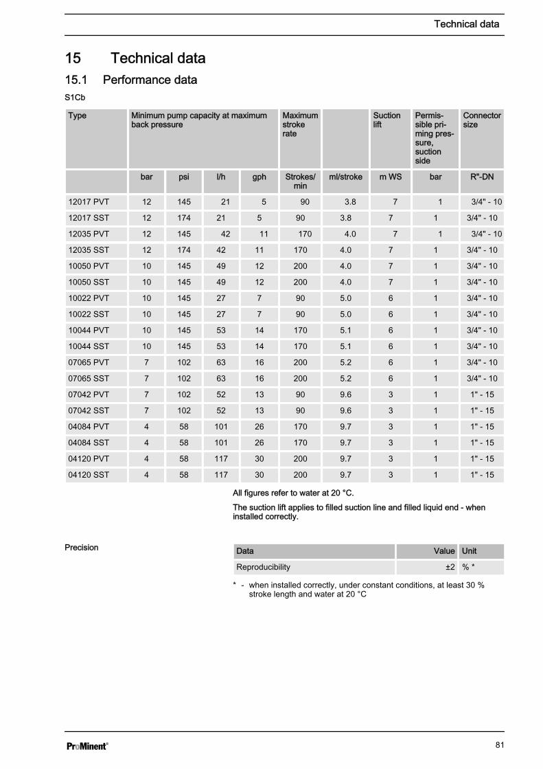
15 Technical data15.1 Performance data
Type Minimum pump capacity at maximumback pressure
Maximumstrokerate
Suctionlift
Permis‐sible pri‐ming pres‐sure,suctionside
Connectorsize
bar psi l/h gph Strokes/min
ml/stroke m WS bar R"-DN
12017 PVT 12 145 21 5 90 3.8 7 1 3/4" - 10
12017 SST 12 174 21 5 90 3.8 7 1 3/4" - 10
12035 PVT 12 145 42 11 170 4.0 7 1 3/4" - 10
12035 SST 12 174 42 11 170 4.0 7 1 3/4" - 10
10050 PVT 10 145 49 12 200 4.0 7 1 3/4" - 10
10050 SST 10 145 49 12 200 4.0 7 1 3/4" - 10
10022 PVT 10 145 27 7 90 5.0 6 1 3/4" - 10
10022 SST 10 145 27 7 90 5.0 6 1 3/4" - 10
10044 PVT 10 145 53 14 170 5.1 6 1 3/4" - 10
10044 SST 10 145 53 14 170 5.1 6 1 3/4" - 10
07065 PVT 7 102 63 16 200 5.2 6 1 3/4" - 10
07065 SST 7 102 63 16 200 5.2 6 1 3/4" - 10
07042 PVT 7 102 52 13 90 9.6 3 1 1" - 15
07042 SST 7 102 52 13 90 9.6 3 1 1" - 15
04084 PVT 4 58 101 26 170 9.7 3 1 1" - 15
04084 SST 4 58 101 26 170 9.7 3 1 1" - 15
04120 PVT 4 58 117 30 200 9.7 3 1 1" - 15
04120 SST 4 58 117 30 200 9.7 3 1 1" - 15
All figures refer to water at 20 °C.
The suction lift applies to filled suction line and filled liquid end - wheninstalled correctly.
Data Value Unit
Reproducibility ±2 % *
* - when installed correctly, under constant conditions, at least 30 %stroke length and water at 20 °C
S1Cb
Precision
Technical data
81
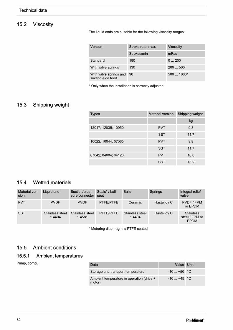
15.2 ViscosityThe liquid ends are suitable for the following viscosity ranges:
Version Stroke rate, max. Viscosity
Strokes/min mPas
Standard 180 0 ... 200
With valve springs 130 200 ... 500
With valve springs andsuction-side feed
90 500 ... 1000*
* Only when the installation is correctly adjusted
15.3 Shipping weightTypes Material version Shipping weight
kg
12017; 12035; 10050 PVT 9.8
SST 11.7
10022; 10044; 07065 PVT 9.8
SST 11.7
07042; 04084; 04120 PVT 10.0
SST 13.2
15.4 Wetted materialsMaterial ver‐sion
Liquid end Suction/pres‐sure connector
Seals* / ballseat
Balls Springs Integral reliefvalve
PVT PVDF PVDF PTFE/PTFE Ceramic Hastelloy C PVDF / FPMor EPDM
SST Stainless steel1.4404
Stainless steel1.4581
PTFE/PTFE Stainless steel1.4404
Hastelloy C Stainlesssteel / FPM or
EPDM
* Metering diaphragm is PTFE coated
15.5 Ambient conditions15.5.1 Ambient temperatures
Data Value Unit
Storage and transport temperature -10 ... +50 °C
Ambient temperature in operation (drive +motor):
-10 ... +45 °C
Pump, compl.
Technical data
82
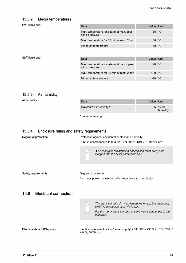
15.5.2 Media temperatures
Data Value Unit
Max. temperature long-term at max. oper‐ating pressure
65 °C
Max. temperature for 15 min at max. 2 bar 100 °C
Minimum temperature -10 °C
Data Value Unit
Max. temperature long-term at max. oper‐ating pressure
90 °C
Max. temperature for 15 min at max. 2 bar 120 °C
Minimum temperature -10 °C
15.5.3 Air humidity
Data Value Unit
Maximum air humidity *: 95 % rel.humidity
* non-condensing
15.5.4 Enclosure rating and safety requirementsProtection against accidental contact and humidity:
IP 65 in accordance with IEC 529, EN 60529, DIN VDE 0470 Part 1
A CAN plug or the supplied sealing cap must always beplugged into the CAN port for the HMI.
Degree of protection:
1 - mains power connection with protective earth conductor
15.6 Electrical connection
The electrical data do not relate to the motor, but the pump,which is connected as a whole unit.For the motor electrical data use the motor data sheet in theappendix.
Identity code specification "power supply" - "U": 100 - 230 V ± 10 %, 240 V± 6 %, 50/60 Hz
PVT liquid end
SST liquid end
Air humidity
Degree of protection
Safety requirements
Electrical data S1Cb pump
Technical data
83

Data Value Unit
Capacity 110 W
Max. starting current 8.5 A
Electrical data at 100 VAC
Data Value Unit
Effective current 1.5 A
Switch on peak current, (for approx. 100ms)
4 A
Electrical data at 230 VAC
Data Value Unit
Effective current 0.6 A
Switch on peak current, (for approx. 100ms)
8 A
Fuses
Fuse Value Part no.
Fuse, internal 3.15 AT - (1.5 kA) 732414
Only use the original fuses from ProMinent! It is not sufficientto use a fuse with the above fuse rating.
15.7 Diaphragm rupture sensor
Contact loading, max.
at voltage Maximum current
30 V DC 1 A
The contact is an opener.
The contact is an potential-free.
– For safety reasons we recommend connecting to a pro‐tective low voltage, e.g. in accordance with EN 60335-1(SELV ).
– The cable can be poled as required.
15.8 Relay
The technical data for the relay are contained in the chapter"Installation, electrical".
Contact (standard)
Technical data
84

15.9 Sound pressure levelSound pressure level LpA < 70 dB according to EN ISO 20361
at maximum stroke length, maximum stroke rate, maximum back pressure(water)
Sound pressure level
Technical data
85
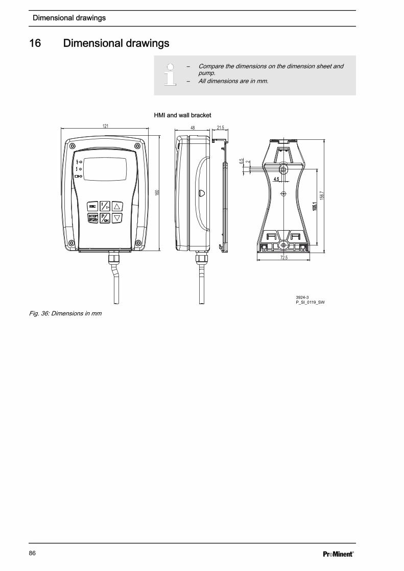
16 Dimensional drawings
– Compare the dimensions on the dimension sheet andpump.
– All dimensions are in mm.
HMI and wall bracket
2
105.1
72.5
156.716
0
121 48 21.5
6.5
4.5
3924-3P_SI_0119_SW
Fig. 36: Dimensions in mm
Dimensional drawings
86
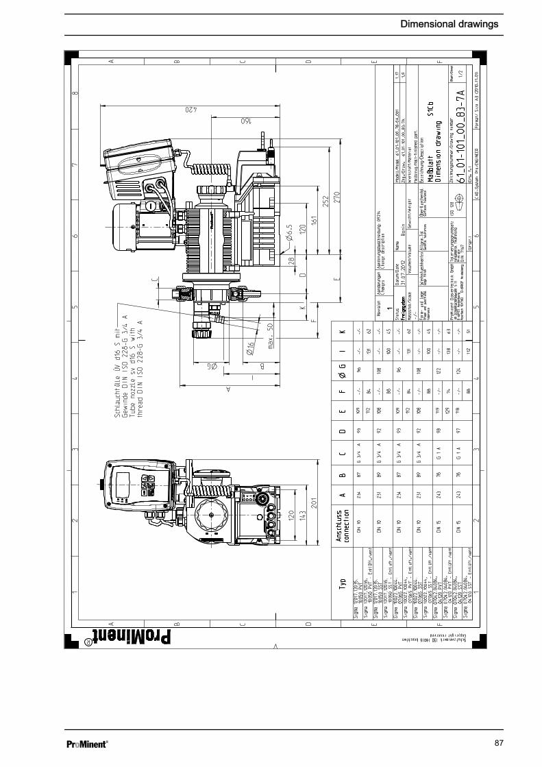
Dimensional drawings
87
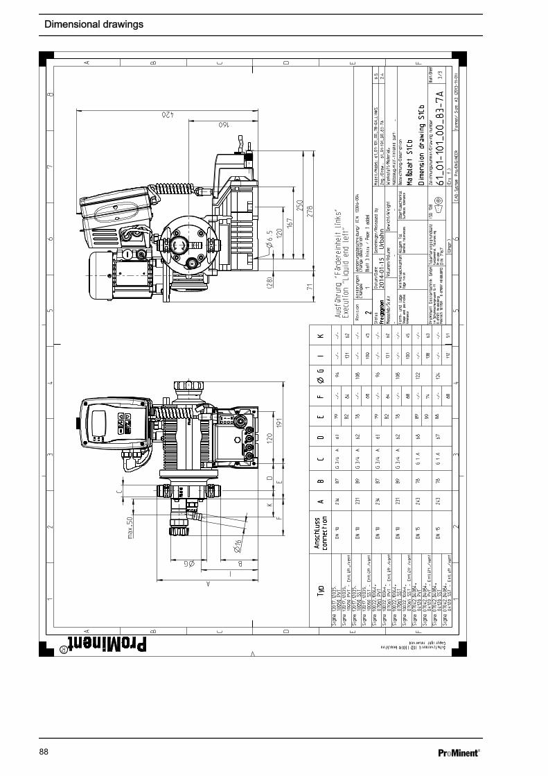
EDCBA
87
65
43
21
A B C D E F
12
34
Format/ Size: A3 (2013-11-01)
65
F
Schutzvermerk ISO 16016 beachtenCopyright reserved
ProMinent
CAD-System: Pro/ENGINEER
Blatt 3 hinzu / Page 3 added
1
2
Aenderungsbeschreibung/ ECN:
13306-004
Change description
Aenderungen
Changes
Revision
(Ers. f.:)
(Urspr.)
3/3
61_01-101_00_83-7A
ISO 128
Tolerierungsgrundsatz
Fundamental Tolerancing
Principle
DIN 7167
ProMinent Dosiertechnik GmbH
Im Schuhmachergewann 5-11
D-69123 Heidelberg
Postfach 101760 D-69007 Heidelberg
Blatt/Sheet
Zeichnungsnummer/Drawing number
Dimension drawing S1Cb
Oberflaechentol.
Surfaces tolerance
Allgem.Tol.
General tolerances
Werkstueckkanten
Edge finish
Form- und Lage
Shape and positional
tolerance
Maßblatt S1Cb
Bezeichnung/Description
-Halbzeug/Half-finished part:
--
-Werkstoff/Material:
Gewicht/Weight
Volumen/Volume
Massstab/Scale
2.4
Zng./Draw.: 61_01-101_00_83-7A
Freigegeben
6.5
Modell/Model: 61_01-101_00_78-0A_LINKS
Genehmiger/Released by
Datum/Date
Status
Typ
Anschluss
connection
AB
CD
EF
G
IK
Sigma 12017,12035,
10050 PVT
DN 10
234
87
G 3/4 A
63
79
-/-
96
-/-
-/-
Sigma 12017,12035,
10050 PVT - Entlüft./vent
82
84
131
62
Sigma 12017,12035,
10050 SST
DN 10
231
89
G 3/4 A
62
78
-/-
108
-/-
-/-
Sigma 12017,12035,
10050 SST - Entlüft./vent
88
100
45
Sigma 10022,10044,
07065 PVT
DN 10
234
87
G 3/4 A
63
79
-/-
96
-/-
-/-
Sigma 10022,10044,
07065 PVT - Entlüft./vent
82
84
131
62
Sigma 10022,10044,
07065 SST
DN 10
231
89
G 3/4 A
62
78
-/-
108
-/-
-/-
Sigma 10022,10044,
07065 SST - Entlüft./vent
88
100
45
Sigma 07042,04084,
04120 PVT
DN 15
243
78
G 1 A
68
89
-/-
122
-/-
-/-
Sigma 07042,04084,
04120 PVT - Entlüft./vent
99
74
138
63
Sigma 07042,04084,
04120 SST
DN 15
243
78
G 1 A
67
88
-/-
124
-/-
-/-
Sigma 07042,04084,
04120 SST - Entlüft./vent
88
112
51
Ausführung "Fördereinheit links"
Execution "Liquid end left"
6.5
(28)
120
160
420
120
167
250
278
191
C
D E
max.50
A
I
BG
F
K
16
71
U
rbah
n20
14-0
1-15
Dimensional drawings
88

17 Motor data sheets
Bestell Nr. / order no. 1042145 Hersteller / producer
no. de commade / No.de pedido producteur / fabricánte
Motor- Typ X_BN 56B 4 230/400-50 IP55 Leistungsfaktor
motor type CLF B5 12649/1000 power factor
type du moteur facteur de puissance
tipo de motor factor de potencia
Maschinenart 3 Ph. Motor Wirkungsgrad
type of machine efficiency
désignation rendement
tipo de máquina rendimiento
Schutzart IP 55 Bemessungsfrequenz
degree of protection rated frequency
degré de protection fréquence nominale
clase de protección frequencia nominal
Bauform B5 Bemessungsdrehzahl 1350/1620 U/min
mounting rated speed rpm
construction vitesse nominale t/mn
Forma constructiva velocidad nominal
Bemessungsleistung 0,09 kW Wärmeklasse
rated output temperature class
puissance nominale class d'isolement
potencia nominal clase térmica
Bemessungsspannung / ∆ Anzugsstrom 2,6 fach
rated voltage 400/230 V (+/- 10%) starting current fold
tension nominale courant de démarrage fois
tension nominal correinte de arranque veces
Bemessungsstrom 0,42 A bei / at 400 V Anzugsmoment 2,4 fach
rated current starting torque fold
courant nominale couple de démarrage fois
corriente nominal par de arranque veces
Geprüft nach Kippmoment 2,5 fach
tested in acc. with CEI EN 60034-1 pull-out torque fold
contrôlé selon couple de décrochage fois
testado de acuerdo a par de inversión veces
ATEX Nr. Umgebungstemperatur
ambient temperature
température ambiante
temperatura ambiente
Ex-Schutzklasse Schaltung
ex-protective system connection
class de protection Ex branchement
clase de protección Ex conexiónDrehzahlregelbereich
speed ajustment range
Anmerkung
comments
observation
observación
ProMinentPumpentyp
pump type S1CbH _ _ _ _ _ _ _ _ _ _ _ _ U _ _ _ _ _ _
type de pompetipo de bomba
ProMinent Dosiertechnik GmbH . 69123 Heidelberg . Germany No. MD-1042145 Datum/Date August 2012
Die Daten entsprechen den Angaben der Motorenhersteller. Kenndaten funktionsgleicher Motoren anderer Hersteller ändern sich nur unwesentlich. Angaben ohne Gewähr. The data correspond to the details given by the motor manufacturers. Ratings of motors with the same functions made by other producers show insignificant changes only. This information is supplied without liability. Les données techniques correspondent au descriptif du fabricant des moteurs. Les données techniques des moteurs similaires chez d’ autres fabricants varient très peu. Données sont d’ ordre général.Los datos corresponden la información obtenida por el fabricante de Motores. Las caracteristicas del funcionamiento identico de los Motores de otros fabricantes cambian solo marginalmente. A la Información no se asuma responsabilidad.
Übersetzung / drive ratio / rapport de transmission / relación de transmisiòn: 20:1
Getriebemotor / drive motor / motoréducteur / motorreductor
Motor Datenblatt / Motor data sheet /
Fiche technique pour moteur / Hoja de datos del motor
-15° C - +40° C
51,7 % (100 %)
47,6 % (75 %)
50 / 60 Hz
0,6
Bonfiglioli(W83032050790023)
/ ∆
F
Motor data sheets
89
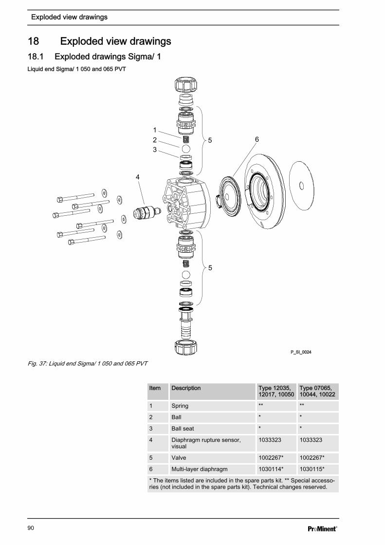
18 Exploded view drawings18.1 Exploded drawings Sigma/ 1
P_SI_0024
15
4
5
623
Fig. 37: Liquid end Sigma/ 1 050 and 065 PVT
Item Description Type 12035,12017, 10050
Type 07065,10044, 10022
1 Spring ** **
2 Ball * *
3 Ball seat * *
4 Diaphragm rupture sensor,visual
1033323 1033323
5 Valve 1002267* 1002267*
6 Multi-layer diaphragm 1030114* 1030115*
* The items listed are included in the spare parts kit. ** Special accesso‐ries (not included in the spare parts kit). Technical changes reserved.
Liquid end Sigma/ 1 050 and 065 PVT
Exploded view drawings
90
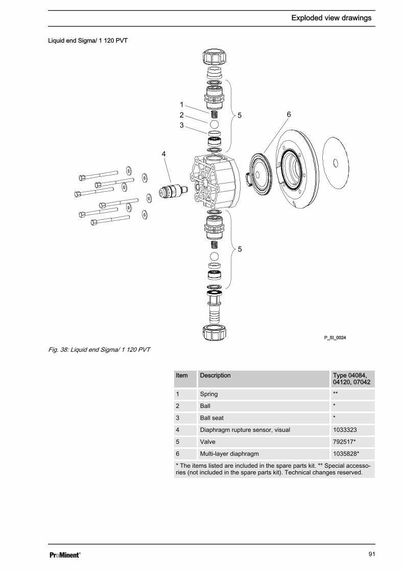
P_SI_0024
15
4
5
623
Fig. 38: Liquid end Sigma/ 1 120 PVT
Item Description Type 04084,04120, 07042
1 Spring **
2 Ball *
3 Ball seat *
4 Diaphragm rupture sensor, visual 1033323
5 Valve 792517*
6 Multi-layer diaphragm 1035828*
* The items listed are included in the spare parts kit. ** Special accesso‐ries (not included in the spare parts kit). Technical changes reserved.
Liquid end Sigma/ 1 120 PVT
Exploded view drawings
91
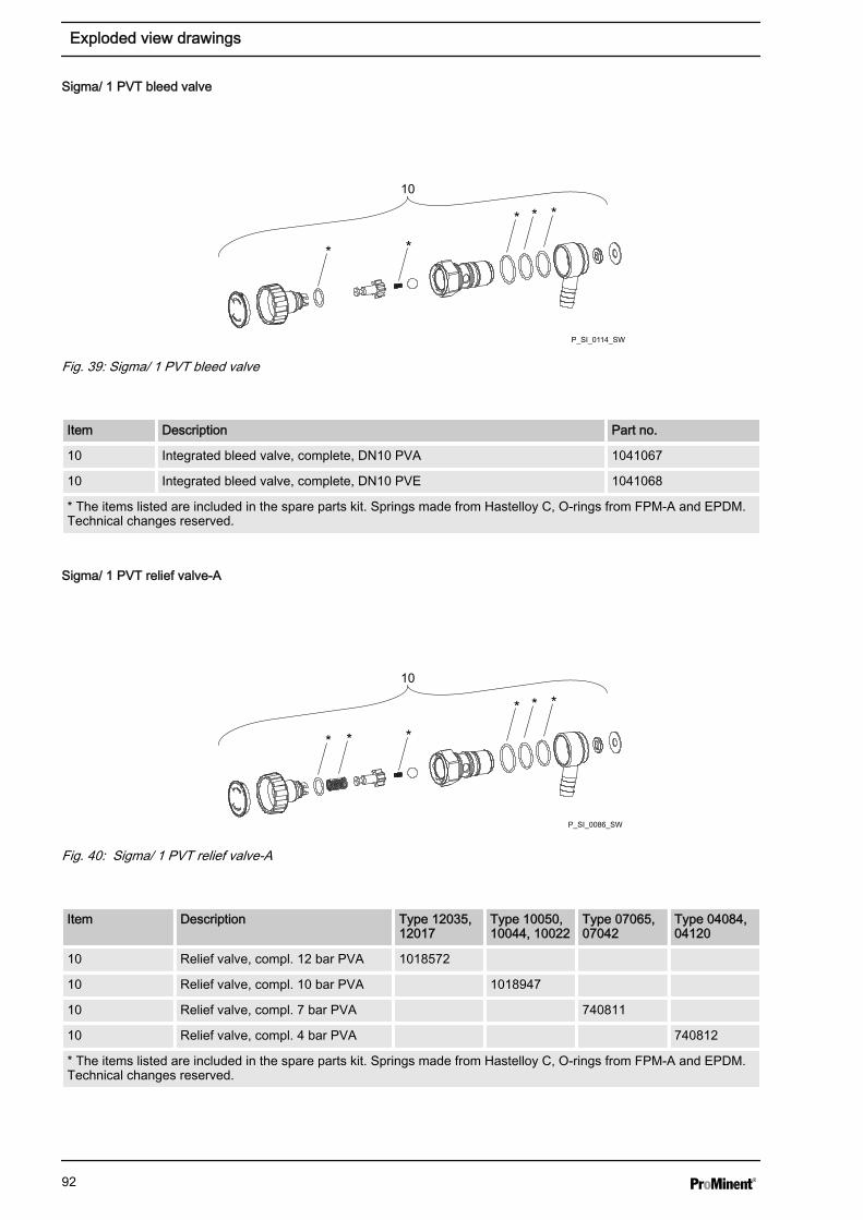
P_SI_0114_SW
***
**
10
Fig. 39: Sigma/ 1 PVT bleed valve
Item Description Part no.
10 Integrated bleed valve, complete, DN10 PVA 1041067
10 Integrated bleed valve, complete, DN10 PVE 1041068
* The items listed are included in the spare parts kit. Springs made from Hastelloy C, O-rings from FPM-A and EPDM.Technical changes reserved.
P_SI_0086_SW
***
** *
10
Fig. 40: Sigma/ 1 PVT relief valve-A
Item Description Type 12035,12017
Type 10050,10044, 10022
Type 07065,07042
Type 04084,04120
10 Relief valve, compl. 12 bar PVA 1018572
10 Relief valve, compl. 10 bar PVA 1018947
10 Relief valve, compl. 7 bar PVA 740811
10 Relief valve, compl. 4 bar PVA 740812
* The items listed are included in the spare parts kit. Springs made from Hastelloy C, O-rings from FPM-A and EPDM.Technical changes reserved.
Sigma/ 1 PVT bleed valve
Sigma/ 1 PVT relief valve-A
Exploded view drawings
92
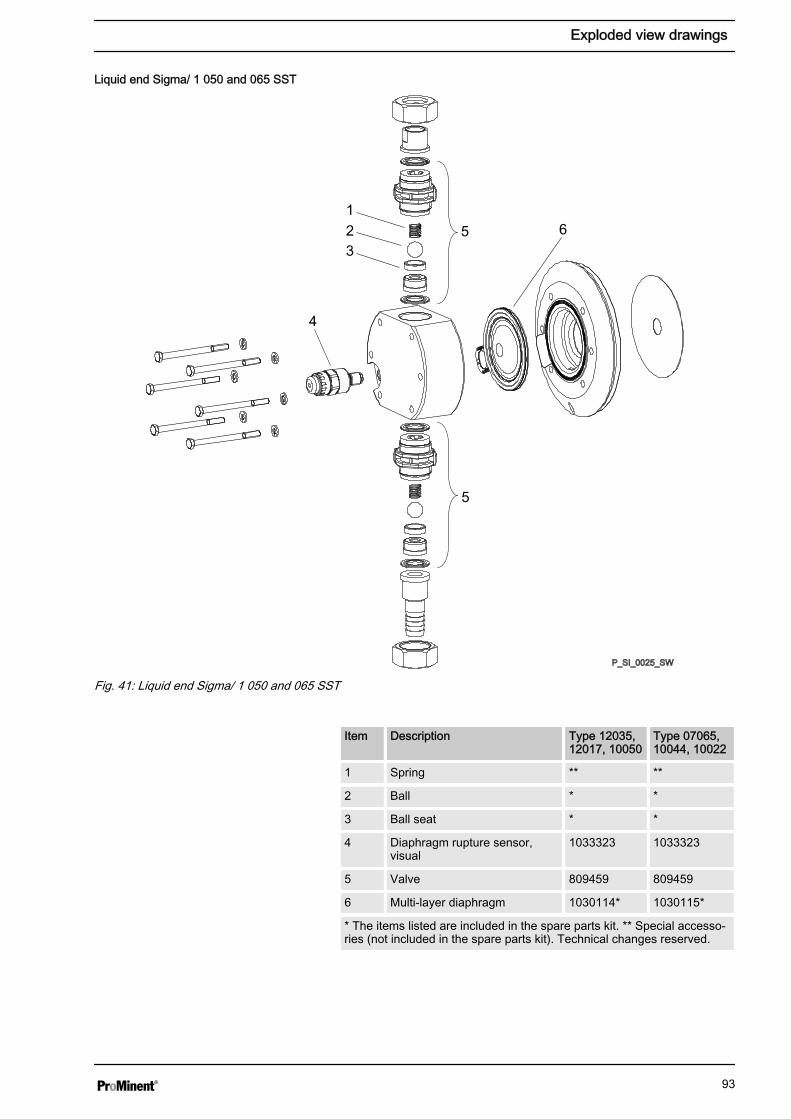
P_SI_0025_SW
15
4
5
623
Fig. 41: Liquid end Sigma/ 1 050 and 065 SST
Item Description Type 12035,12017, 10050
Type 07065,10044, 10022
1 Spring ** **
2 Ball * *
3 Ball seat * *
4 Diaphragm rupture sensor,visual
1033323 1033323
5 Valve 809459 809459
6 Multi-layer diaphragm 1030114* 1030115*
* The items listed are included in the spare parts kit. ** Special accesso‐ries (not included in the spare parts kit). Technical changes reserved.
Liquid end Sigma/ 1 050 and 065 SST
Exploded view drawings
93
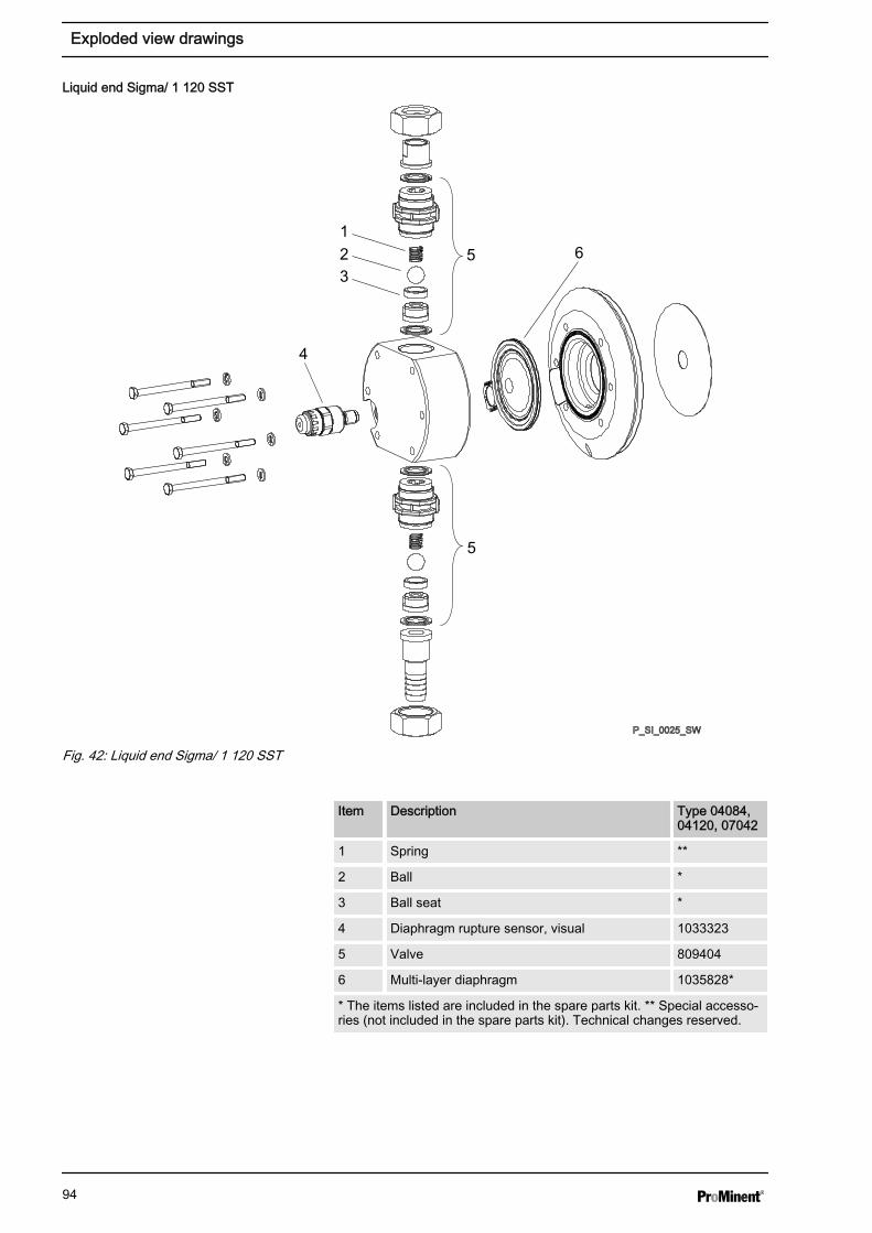
P_SI_0025_SW
15
4
5
623
Fig. 42: Liquid end Sigma/ 1 120 SST
Item Description Type 04084,04120, 07042
1 Spring **
2 Ball *
3 Ball seat *
4 Diaphragm rupture sensor, visual 1033323
5 Valve 809404
6 Multi-layer diaphragm 1035828*
* The items listed are included in the spare parts kit. ** Special accesso‐ries (not included in the spare parts kit). Technical changes reserved.
Liquid end Sigma/ 1 120 SST
Exploded view drawings
94
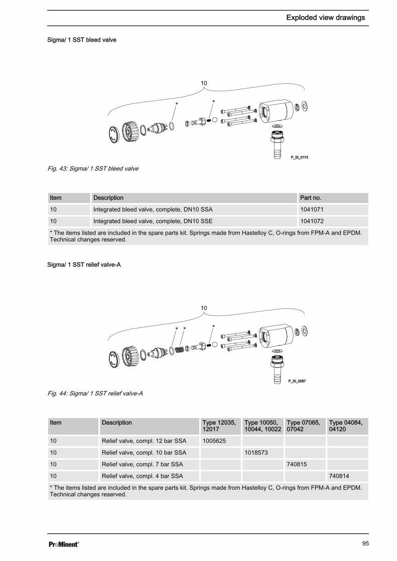
**
P_SI_0113
10
Fig. 43: Sigma/ 1 SST bleed valve
Item Description Part no.
10 Integrated bleed valve, complete, DN10 SSA 1041071
10 Integrated bleed valve, complete, DN10 SSE 1041072
* The items listed are included in the spare parts kit. Springs made from Hastelloy C, O-rings from FPM-A and EPDM.Technical changes reserved.
** *
P_SI_0087
10
Fig. 44: Sigma/ 1 SST relief valve-A
Item Description Type 12035,12017
Type 10050,10044, 10022
Type 07065,07042
Type 04084,04120
10 Relief valve, compl. 12 bar SSA 1005625
10 Relief valve, compl. 10 bar SSA 1018573
10 Relief valve, compl. 7 bar SSA 740815
10 Relief valve, compl. 4 bar SSA 740814
* The items listed are included in the spare parts kit. Springs made from Hastelloy C, O-rings from FPM-A and EPDM.Technical changes reserved.
Sigma/ 1 SST bleed valve
Sigma/ 1 SST relief valve-A
Exploded view drawings
95
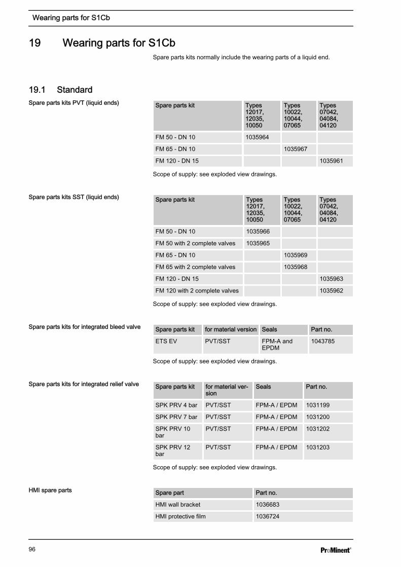
19 Wearing parts for S1CbSpare parts kits normally include the wearing parts of a liquid end.
19.1 StandardSpare parts kit Types
12017,12035,10050
Types10022,10044,07065
Types07042,04084,04120
FM 50 - DN 10 1035964
FM 65 - DN 10 1035967
FM 120 - DN 15 1035961
Scope of supply: see exploded view drawings.
Spare parts kit Types12017,12035,10050
Types10022,10044,07065
Types07042,04084,04120
FM 50 - DN 10 1035966
FM 50 with 2 complete valves 1035965
FM 65 - DN 10 1035969
FM 65 with 2 complete valves 1035968
FM 120 - DN 15 1035963
FM 120 with 2 complete valves 1035962
Scope of supply: see exploded view drawings.
Spare parts kit for material version Seals Part no.
ETS EV PVT/SST FPM-A andEPDM
1043785
Scope of supply: see exploded view drawings.
Spare parts kit for material ver‐sion
Seals Part no.
SPK PRV 4 bar PVT/SST FPM-A / EPDM 1031199
SPK PRV 7 bar PVT/SST FPM-A / EPDM 1031200
SPK PRV 10bar
PVT/SST FPM-A / EPDM 1031202
SPK PRV 12bar
PVT/SST FPM-A / EPDM 1031203
Scope of supply: see exploded view drawings.
Spare part Part no.
HMI wall bracket 1036683
HMI protective film 1036724
Spare parts kits PVT (liquid ends)
Spare parts kits SST (liquid ends)
Spare parts kits for integrated bleed valve
Spare parts kits for integrated relief valve
HMI spare parts
Wearing parts for S1Cb
96

19.2 Physiological safety
Scope of supply with PVT material version
1 x Diaphragm, 2 x Valve balls, 1 x Suction valve, complete, 1 x Discharge valve, complete
1 x Elastomer sealing set (EPDM)
2 x Ball seat housings, 2 x Ball seat discs, 4 x Composite seals
1x Seal washer (for bleed valve or relief valve)
Scope of supply with SST material version
1 x Diaphragm, 2 x Valve balls
2 x Cover rings
4 x Composite seals
1x Seal washer (for bleed valve or relief valve)
Spare parts kits PVT (liquid ends)
Liquid end Types 12017, 12035, 10050 Types 10022, 10044, 07065 Types 07042, 04084, 04120
FM 50 - DN 10 1046466 - -
FM 65 - DN 10 - 1046469 -
FM 120 - DN 15 - - 1046453
Spare parts kits SST (liquid ends)
Liquid end Types 12017, 12035, 10050 Types 10022, 10044, 07065 Types 07042, 04084, 04120
FM 50 - DN 10 1046468 - -
FM 50 - DN 10 with 2valves complete
1046467 - -
FM 65 - DN 10 - 1046471 -
FM 65 - DN 10 with 2valves complete
- 1046470 -
FM 120 - DN 15 - - 1046465
FM 120 - DN 15 with 2valves complete
- - 1046464
Material version Liquid end Suction / pressureconnector
Seals* / ball seat Balls Integral bleedvalve or reliefvalve
PVT PVDF PVDF PTFE / PVDF Ceramic PVDF / EPDM
SST Stainless steel1.4404
Stainless steel1.4581
PTFE / PVDF Stainless steel1.4404
Stainless steel /EPDM
* Metering diaphragm is PTFE-coated; seals are PTFE composite seals
PTFE: FDA No. 21 CFR §177.1550
Spare parts kits
Ordering Information
Wetted materials – "Physiologically safetywith regard to wetted materials" design
Wearing parts for S1Cb
97

PVDF: FDA No. 21 CFR §177.2510
Wearing parts for S1Cb
98
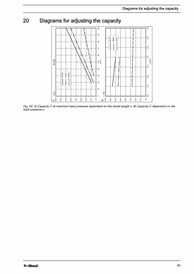
20 Diagrams for adjusting the capacity
p [b
ar]
S [%
]0
1020
3040
5060
7080
9010
0
C [l
/h]
C [l
/h]
A B
S1C
b
0.0
20.0
40.0
60.0
80.0
100.
0
120.
0
140.
0
20.0
40.0
60.0
80.0
100.
0
120.
0
140.
0
160.
0
0.0
1.0
2.0
3.0
4.0
5.0
6.0
7.0
0412
0
0408
4
0704
2
0.0
160.
0
0412
0
0408
4
0704
2
Fig. 45: A) Capacity C at maximum back pressure dependent on the stroke length s. B) Capacity C dependent on theback pressure p.
Diagrams for adjusting the capacity
99
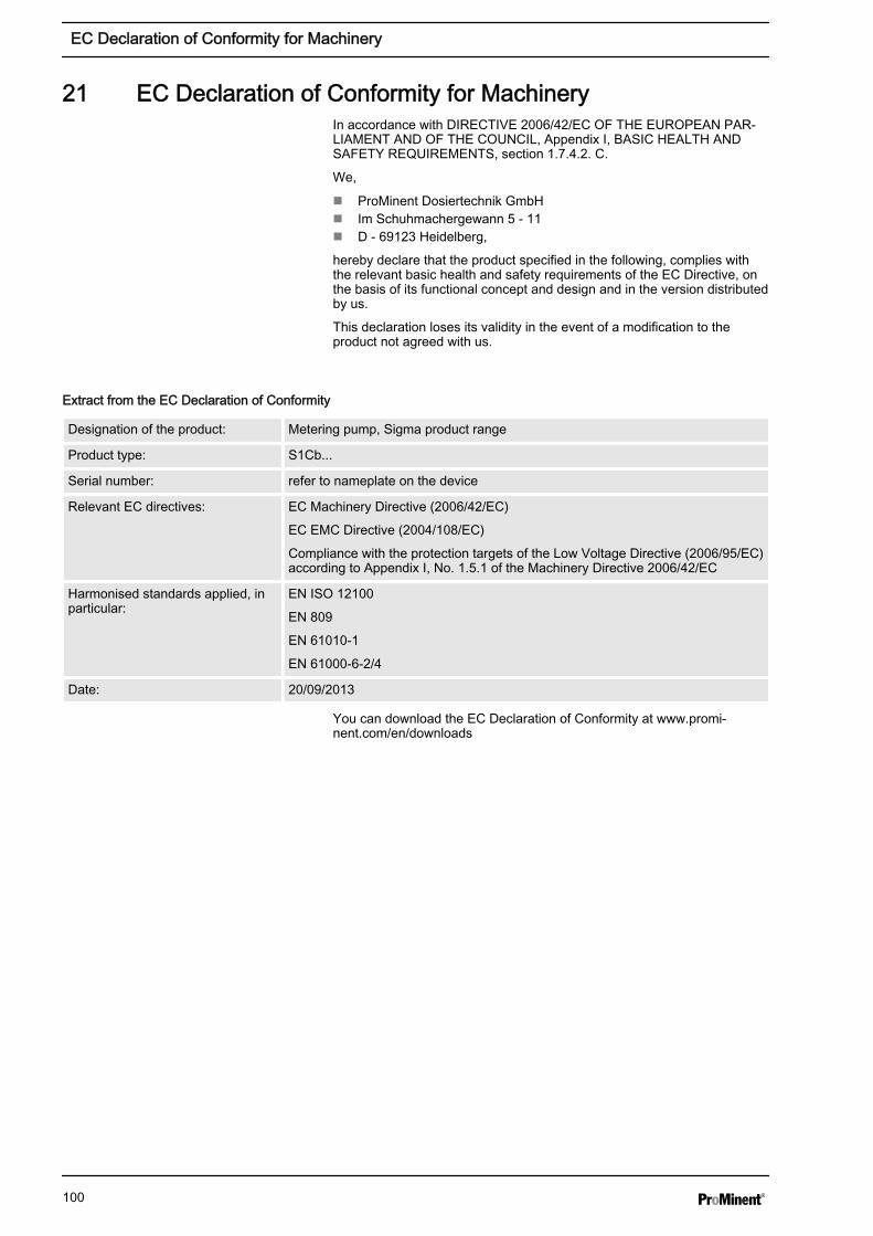
21 EC Declaration of Conformity for MachineryIn accordance with DIRECTIVE 2006/42/EC OF THE EUROPEAN PAR‐LIAMENT AND OF THE COUNCIL, Appendix I, BASIC HEALTH ANDSAFETY REQUIREMENTS, section 1.7.4.2. C.
We,
n ProMinent Dosiertechnik GmbHn Im Schuhmachergewann 5 - 11n D - 69123 Heidelberg,
hereby declare that the product specified in the following, complies withthe relevant basic health and safety requirements of the EC Directive, onthe basis of its functional concept and design and in the version distributedby us.
This declaration loses its validity in the event of a modification to theproduct not agreed with us.
Extract from the EC Declaration of Conformity
Designation of the product: Metering pump, Sigma product range
Product type: S1Cb...
Serial number: refer to nameplate on the device
Relevant EC directives: EC Machinery Directive (2006/42/EC)
EC EMC Directive (2004/108/EC)
Compliance with the protection targets of the Low Voltage Directive (2006/95/EC)according to Appendix I, No. 1.5.1 of the Machinery Directive 2006/42/EC
Harmonised standards applied, inparticular:
EN ISO 12100
EN 809
EN 61010-1
EN 61000-6-2/4
Date: 20/09/2013
You can download the EC Declaration of Conformity at www.promi‐nent.com/en/downloads
EC Declaration of Conformity for Machinery
100
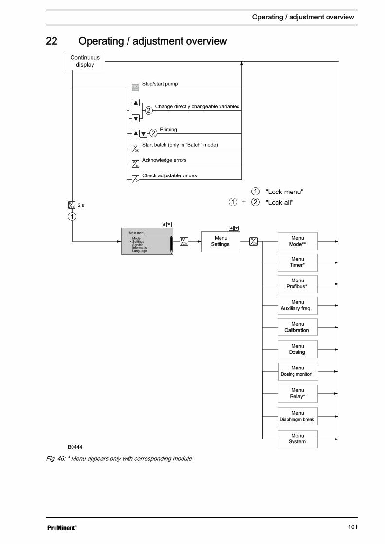
22 Operating / adjustment overviewContinuous
display
2 s
1
1 2+ "Lock all"
1 "Lock menu"
2
2
Stop/start pump
Change directly changeable variables
Priming
Start batch (only in "Batch" mode)
Acknowledge errors
Check adjustable values
MenuSettingsSettings
MenuMode**Mode**
MenuTimer*Timer*
MenuProfibus*Profibus*
MenuAuxiliary freq.Auxiliary freq.
MenuDosing monitor*Dosing monitor*
MenuCalibrationCalibration
MenuDosingDosing
MenuRelay*Relay*
MenuDiaphragm breakDiaphragm break
MenuSystemSystem
Main menuModeSettingsServiceInformationLanguage
B0444
Fig. 46: * Menu appears only with corresponding module
Operating / adjustment overview
101
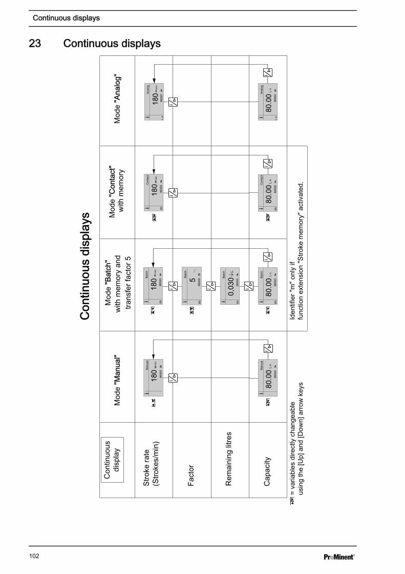
23 Continuous displays
Con
tinuo
usdi
spla
y
Con
tinuo
us d
ispl
ays
Con
tinuo
us d
ispl
ays
Mod
e "M
anua
l""M
anua
l"M
ode
"Bat
ch"
"Bat
ch"
with
mem
ory
and
trans
fer f
acto
r 5
Mod
e "C
onta
ct"
"Con
tact
" w
ith m
emor
yM
ode
"Ana
log"
"Ana
log"
Stro
ke ra
te(S
troke
s/m
in)
Cap
acity
Fact
or
Iden
tifie
r "m
" onl
y if
func
tion
exte
nsio
n "S
troke
mem
ory"
act
ivat
ed.
= va
riabl
es d
irect
ly c
hang
eabl
e us
ing
the
[Up]
and
[Dow
n] a
rrow
key
s
8650
0Man
ual
180
/min
8650
0Man
ual
80.0
0/h
8650
0Bat
ch
180
8650
0Bat
ch
0,03
0
/min
8650
0Bat
ch
5
8650
0Con
tact
180
/min
8650
0Ana
log
0..2
0
180
/min
8650
0Ana
log
80.0
0/h
0..2
0
Rem
aini
ng li
tres
8650
0Bat
ch
80.0
0/h
8650
0Con
tact
80.0
0/h
Continuous displays
102
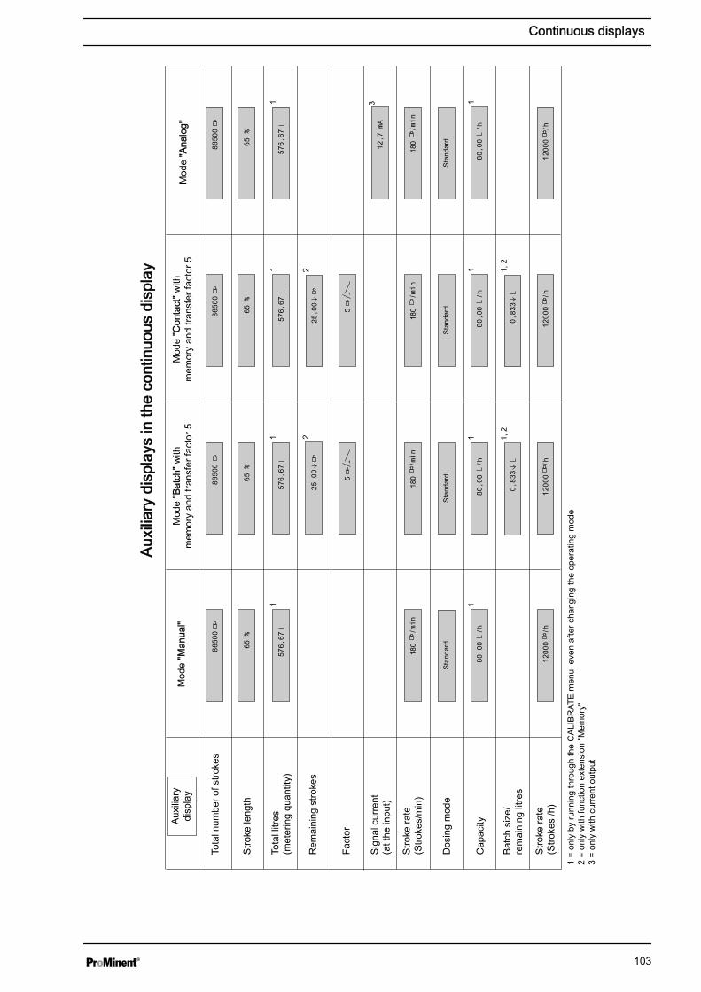
Aux
iliar
ydi
spla
y
Aux
iliar
y di
spla
ys in
the
cont
inuo
us d
ispl
ayA
uxili
ary
disp
lays
in th
e co
ntin
uous
dis
play
Mod
e "M
anua
l"M
ode
"Bat
ch" w
ithm
emor
y an
d tra
nsfe
r fac
tor 5
Mod
e "C
onta
ct" w
ithm
emor
y an
d tra
nsfe
r fac
tor 5
Mod
e "A
nalo
g"
Stro
ke ra
te(S
troke
s /h
)
Stro
ke ra
te(S
troke
s/m
in)
Cap
acity
Fact
or
Tota
l litr
es(m
eter
ing
quan
tity)
Stro
ke le
ngth
Sig
nal c
urre
nt(a
t the
inpu
t)
Dos
ing
mod
e
Tota
l num
ber o
f stro
kes
Bat
ch s
ize/
rem
aini
ng li
tres
Rem
aini
ng s
troke
s
1 =
only
by
runn
ing
thro
ugh
the
CA
LIB
RAT
E m
enu,
eve
n af
ter c
hang
ing
the
oper
atin
g m
ode
2 =
only
with
func
tion
exte
nsio
n "M
emor
y"3
= on
ly w
ith c
urre
nt o
utpu
t
1, 2
1
2 1, 2
1 1
11 3
11
1
2
Continuous displays
103
24 Index""External control" terminal............................................. 371, 2, 3 ...4 - 20 mA....................................................................... 49AAccess protect............................................................... 60Adjustment, chapter...................................................... 42Adjustment mode.......................................................... 43Air humidity................................................................... 83Ambient conditions........................................................ 82Analog............................................................... 21, 23, 49Analog current output.................................................... 22Analog error.................................................................. 51Analog output................................................................ 57Applied harmonised standards.................................... 100Assembly....................................................................... 24AUX............................................................................... 52Auxiliary frequency................................ 21, 23, 37, 52, 55BBasic principles of control adjustment........................... 42Batch................................................................. 21, 23, 45Bleeder valve................................................................ 28Bleed valve.................................................................... 13BUS............................................................................... 21CCalibrate........................................................................ 53Calibration..................................................................... 21CAN bus.................................................................. 13, 39CANopen status indicator............................................. 22Capacity.................................................................. 81, 99Cavitation...................................................................... 54Checking adjustable values.......................................... 42Cleaning valves............................................................. 69CLEAR COUNTERS..................................................... 58Climate.......................................................................... 83Connector size.............................................................. 81Contact........................................................ 21, 23, 46, 84Continuous displays...................................................... 42Contrast......................................................................... 59Control........................................................................... 55Control elements........................................................... 13Current output............................................................... 34DDecommissioning.......................................................... 79Decontamination declaration......................................... 12Degree of protection...................................................... 83Designation of the product.......................................... 100Diagrams....................................................................... 99Diaphragm..................................................................... 19Diaphragm break........................................................... 57
Diaphragm rupture sensor...................................... 13, 84Dimensional drawings................................................... 86Dimension sheet HMI + wall bracket............................. 86Discharge opti............................................................... 54Discharge valve............................................................. 19DISPLAY....................................................................... 59Disposal........................................................................ 80Dosing..................................................................... 54, 55Dosing head.................................................................. 19Dosing monitor.............................................................. 55Dosing profile................................................................ 54Draining the liquid end.................................................. 80Drive motor.................................................................... 13Drive unit....................................................................... 13EElectrical data................................................................ 83Emergency.................................................................... 11Error........................................................................ 23, 55Error messages............................................................. 42Extended................................................................. 49, 51External analog............................................................. 23External contact...................................................... 23, 37External frequency changeover.................................... 23FFactor...................................................................... 45, 46Fault indicating / pacing relay (24 V)............................. 34Fault indicating relay..................................................... 22Fault indicating relay (24 V).......................................... 33Fault indicating relay 230 V........................................... 33Fault indicator.......................................................... 13, 22Fault processing............................................................ 51Fault statuses................................................................ 23Flow......................................................................... 21, 55Function indicator.......................................................... 22Functions................................................................. 21, 23Function settings........................................................... 52GGallon............................................................................ 58Gaseous feed chemicals............................................... 54HHardware versions........................................................ 61Hierarchy of operating modes....................................... 23HMI.......................................................................... 25, 39HMI login....................................................................... 59HMI logout..................................................................... 59HMI operating unit......................................................... 39IIdentification of safety notes............................................ 8Identity Code ................................................................ 61Information.................................................................... 61
Index
104
Information in the event of an emergency..................... 11Installation..................................................................... 26Integral bleeder valve.................................................... 28Integral relief valve........................................................ 28Intended use................................................................... 8IP................................................................................... 83KKeys........................................................................ 13, 15LLanguage...................................................................... 61Leakage hole................................................................. 68LED............................................................................... 13Level switch................................................................... 22Linear............................................................................ 50Liquid end................................................................ 13, 19Liter............................................................................... 58MMaintenance.................................................................. 67Manual.............................................................. 21, 23, 45Manual operation.......................................................... 64mA-Output............................................................... 13, 22Materials........................................................................ 82Memory................................................................... 45, 46Metering pumps without integral relief valve................. 30Mixing, optimal.............................................................. 54Mode............................................................................. 44NNPSH............................................................................ 54OOperating indicator.................................................. 13, 22Operating modes..................................................... 20, 23Operating mode selection............................................. 44Operating mode settings............................................... 44Operation...................................................................... 64Optional module............................................................ 13Options.......................................................................... 22Ordering Information..................................................... 96Output relay................................................................... 22Overload switch-off....................................................... 21Overview of Equipment................................................. 13PPacing relay............................................................ 22, 33Password...................................................................... 60Pause................................................................ 22, 23, 37Power supply................................................................. 40Precision....................................................................... 81Priming.................................................................... 22, 23PROFIBUS®................................................................. 13Protection against accidental contact and humidity...... 83Protection class............................................................. 83Pump capacity............................................................... 81
QQualification of personnel................................................ 9RRadioactive................................................................... 12Relay............................................................................. 55Relay behaviour............................................................ 55Relay output.................................................................. 13Relevant EC directives................................................ 100Relief valve.............................................................. 13, 28Remote operation.......................................................... 66Repairs.......................................................................... 69Replacing the diaphragm.............................................. 71Reproducibility............................................................... 81Return line..................................................................... 30SSafety chapter................................................................. 8Safety requirements...................................................... 83Scope of supply............................................................. 12Secondary displays....................................................... 43Security......................................................................... 60Semiconductor relay......................................... 22, 33, 34Serial number ....................................................... 61, 100SERVICE...................................................................... 58Shipping weight............................................................. 82Sideband....................................................................... 51Signalization.................................................................. 55Sockets......................................................................... 13Software versions.......................................................... 61Sound pressure level.............................................. 11, 85Spare parts kits............................................................. 96Standard........................................................................ 49Standard installation...................................................... 31Start up.......................................................................... 62Status LED CAN bus, internal....................................... 13Stop......................................................................... 22, 23Storage.......................................................................... 12Storage and transport temperature............................... 82Stroke length........................................................... 61, 63Stroke length adjustment wheel.................................... 13Suction lift...................................................................... 81Suction opti................................................................... 54Suction valve................................................................. 19Symbols........................................................................ 31System.......................................................................... 58TTemperatures................................................................ 82Timer............................................................................. 13Tolerance...................................................................... 55Total litres...................................................................... 58Total number of strokes................................................ 58Transport....................................................................... 12
Index
105

UUnit................................................................................ 58Unpacking..................................................................... 12VVersions........................................................................ 61Viscosity.................................................................. 54, 82WWall bracket.................................................................. 86Warning......................................................................... 55
Warning indicator.................................................... 13, 22Warning sign................................................................... 8Weight........................................................................... 82Wetted materials........................................................... 82
Index
106

107

985451, 4, en_GB
© 2012
ProMinent GmbHIm Schuhmachergewann 5-1169123 HeidelbergGermanyTelephone: +49 6221 842-0Fax: +49 6221 842-612email: [email protected]: www.prominent.com
Recommended


![T-dualization of type II superstring theory in double space2.1 Type II superstring in pure spinor formulation The sigma model action for the type II superstring of Ref. [45]isoftheform](https://img.pdfslide.net/doc/110x75/5f62f88e1bd1cb48213457dc/t-dualization-of-type-ii-superstring-theory-in-double-space-21-type-ii-superstring.jpg)