Dr. SchelenzFolie 1
13. Fachkongress Zukunftsenergien, 10.Feb. 2009, Essen
Simulation der dynamischen Beanspruchungen des p gAntriebsstranges von WEAUniv.-Prof. Dr.-Ing. G. Jacobs,Dr.-Ing. R. Schelenz,Dipl.-Ing. D. Möller
Simulation der dynamischen Beanspruchungendes Antriebsstranges von WEA
Dr. SchelenzFolie 2
Team IME
Staff:Institute head: professor & 2 chief engineers19 scientific assistants20 employees secretary, measurement,
computer lab, mechanical workshop,50 salaried students
Payment:60 % government40 % i tifi & i d t i l j t40 % scientific & industrial projectstotal turnover: 4 Mio. Euro per year
1870: root of IME are founded1870: root of IME are founded1966: Prof. Heinz Peeken1992: Prof. P. W. Gold2004: formation of the commercial company2004: formation of the commercial company
TriboDrive GmbH2008: Prof. G. Jacobs
Simulation der dynamischen Beanspruchungendes Antriebsstranges von WEA
Dr. SchelenzFolie 3Interacting systems on a wind turbine
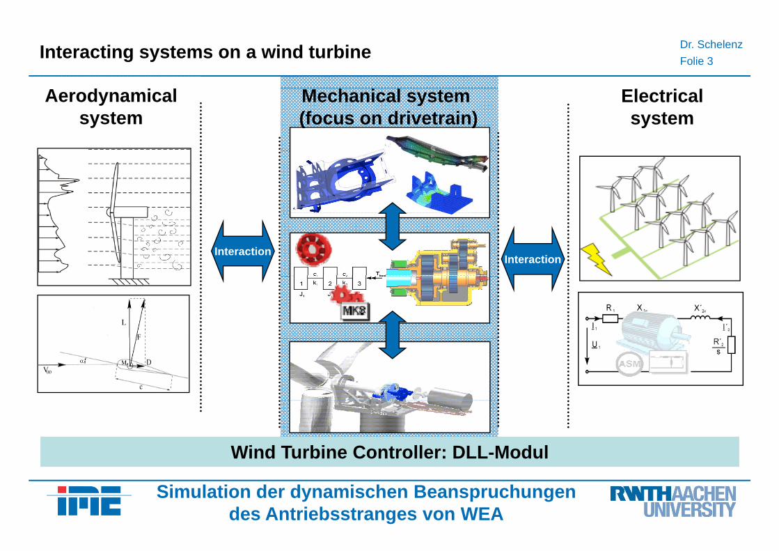
Aerodynamicalsystem
Mechanical system (focus on drivetrain)
Electricalsystem
InteractionInteraction
Wind Turbine Controller: DLL-Modul
Simulation der dynamischen Beanspruchungendes Antriebsstranges von WEA
Dr. SchelenzFolie 4
Powertrain simulation of wind turbines
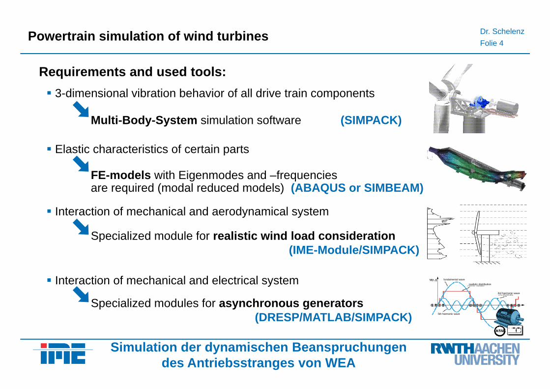
Requirements and used tools:3-dimensional vibration behavior of all drive train components
Elastic characteristics of certain parts
Multi-Body-System simulation software (SIMPACK)
Elastic characteristics of certain parts
FE-models with Eigenmodes and –frequencies are required (modal reduced models) (ABAQUS or SIMBEAM)
Interaction of mechanical and aerodynamical system
Specialized module for realistic wind load consideration
Interaction of mechanical and electrical system fundamental wave
Specialized module for realistic wind load consideration(IME-Module/SIMPACK)
Interaction of mechanical and electrical system
Specialized modules for asynchronous generators(DRESP/MATLAB/SIMPACK)
realistic distribution
3rd harmonic wave
5th harmonic wave
Simulation der dynamischen Beanspruchungendes Antriebsstranges von WEA
Dr. SchelenzFolie 5
DRESP – Torsional Vibration Analysis
Simulation tool developed by the IME and
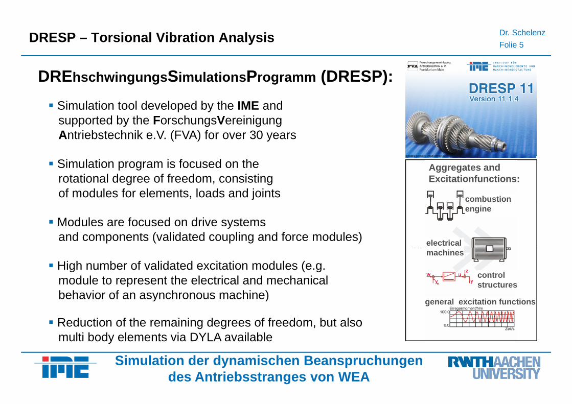
DREhschwingungsSimulationsProgramm (DRESP):p y
supported by the ForschungsVereinigung Antriebstechnik e.V. (FVA) for over 30 years
gears (tolerance,
Machine-elements :
Simulation program is focused on the rotational degree of freedom, consistingof modules for elements, loads and joints
Aggregates and Excitationfunctions:
combustiong (period. stiffness)
hydrodyn. transfer functions
Modules are focused on drive systemsand components (validated coupling and force modules)
engine
electrical functions
dynamical behavior of elastomers
High number of validated excitation modules (e.g. module to represent the electrical and mechanical behavior of an asynchronous machine)
machines
controlstructures
elastomers
wheel/track-and tire/road-contact
behavior of an asynchronous machine)
Reduction of the remaining degrees of freedom, but alsomulti body elements via DYLA available
general excitation functions
Simulation der dynamischen Beanspruchungendes Antriebsstranges von WEA
multi body elements via DYLA available
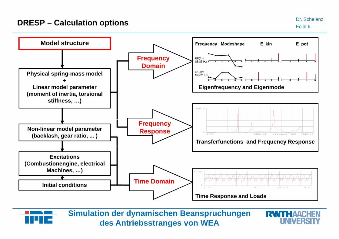
Dr. SchelenzFolie 6DRESP – Calculation options
Frequency Domain
Model structure
Eigenfrequency and Eigenmode
Physical spring-mass model+
Linear model parameter( t f i ti t i l
Domain
(moment of inertia, torsional stiffness, …)
Transferfunctions and Frequency Response
Non-linear model parameter(backlash, gear ratio, ... )
Frequency Response
Excitations (Combustionengine, electrical
Machines, …)
Time Response and Loads
Initial conditions Time Domain
Simulation der dynamischen Beanspruchungendes Antriebsstranges von WEA
Dr. SchelenzFolie 7
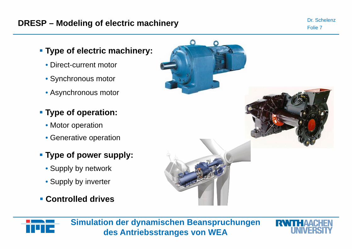
DRESP – Modeling of electric machinery
Type of electric machinery:• Direct-current motor
• Synchronous motor
• Asynchronous motory
Type of operation:• Motor operation• Motor operation• Generative operation
T f lType of power supply:• Supply by network
• Supply by inverter
Controlled drives
• Supply by inverter
Simulation der dynamischen Beanspruchungendes Antriebsstranges von WEA
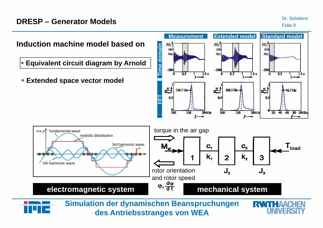
Dr. SchelenzFolie 8DRESP – Generator Models
MeasurementMeasurement Extended modelExtended model Standard modelStandard model
Equivalent circuit diagram by Arnold
Induction machine model based onMeasurementMeasurement Extended modelExtended model Standard modelStandard model
dom
ain
dom
ain
Equivalent circuit diagram by Arnold
Extended space vector model
Tim
e Ti
me
FFT
FFT
torque in the air gapfundamental wave realistic distribution
3rd harmonic wave
5th harmonic wave
Tload
rotor orientationand rotor speed
electromagnetic system mechanical system
Simulation der dynamischen Beanspruchungendes Antriebsstranges von WEA
electromagnetic system mechanical system
Dr. SchelenzFolie 9
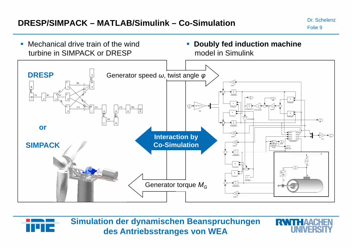
DRESP/SIMPACK – MATLAB/Simulink – Co-Simulation
Mechanical drive train of the wind turbine in SIMPACK or DRESP
Doubly fed induction machinemodel in Simulink
1s
Integrator
R1
Gain
Generator speed ω, twist angle φDRESP
3n
2M
-K-p*(2*pi)/60
T32*Tno* u
T32
Product5
Product4
Product1
Product1s
Integrator4
1s
p
Gain5
emu -K-
1/J/(2*pi)*60
2u1
1Mw
5alpha_mu
4psi2
1i1
K*u
T23
psid1
psiq1
psid2
psiq2
id1
id2
iq1
iq2
Subsystem
1
Integrator1
R2
Gain2
R1
Gain1
Cartesian toPolar
or
SIMPACKInteraction byCo-Simulation
Product3
Product2
s
Integrator2
0
Constant1s
Integrator3
R2
Gain3
Constant
Generator torque MG
Simulation der dynamischen Beanspruchungendes Antriebsstranges von WEA
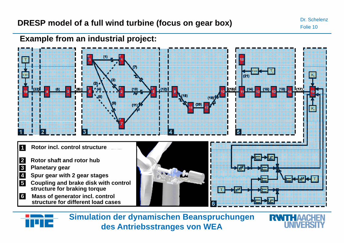
Dr. SchelenzFolie 10DRESP model of a full wind turbine (focus on gear box)
Example from an industrial project:Example from an industrial project:
Rotor incl. control structure1 oto c co t o st uctu e1
4 Spur gear with 2 gear stages3 Planetary gear 2 Rotor shaft and rotor hub
4 Spur gear with 2 gear stages
6 Mass of generator incl. control structure for different load cases
5 Coupling and brake disk with controlstructure for braking torque
Simulation der dynamischen Beanspruchungendes Antriebsstranges von WEA
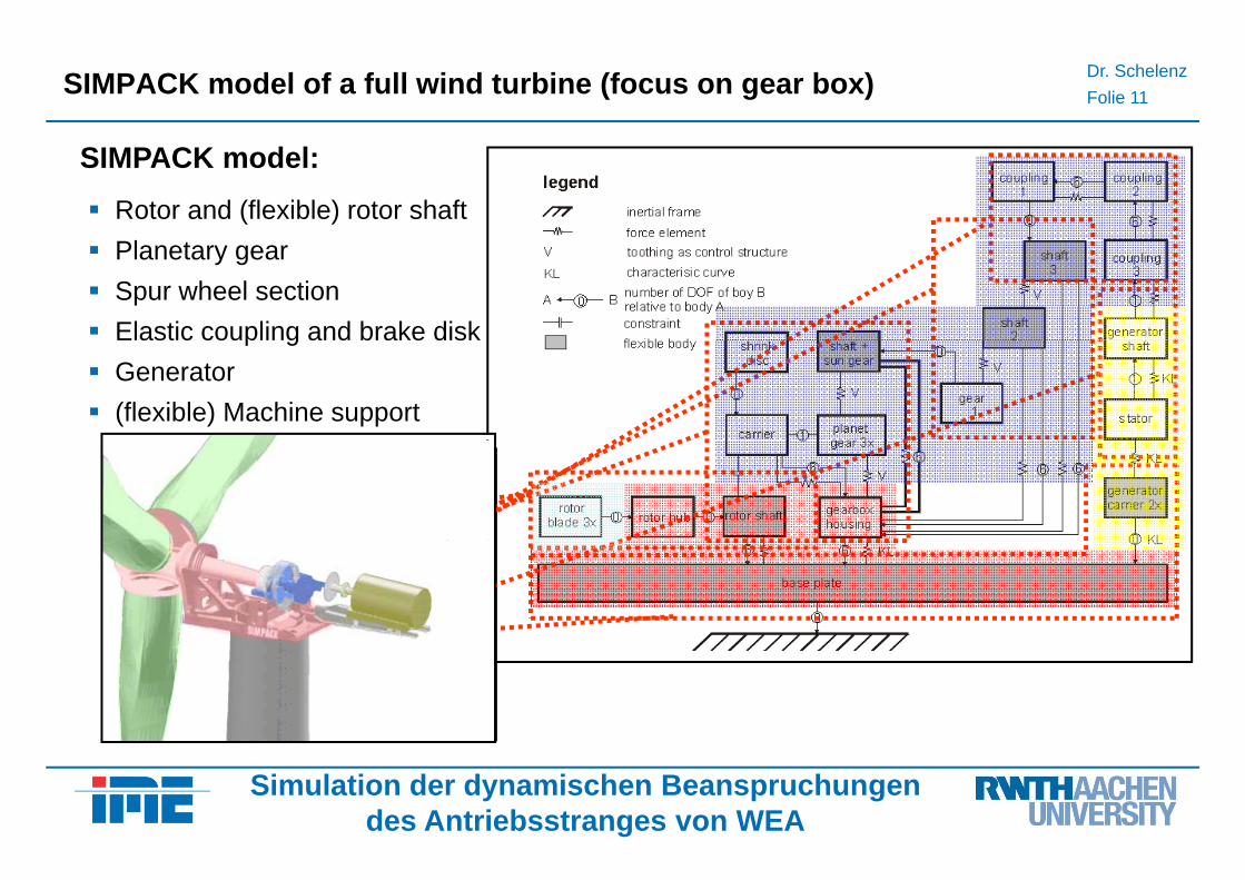
Dr. SchelenzFolie 11SIMPACK model of a full wind turbine (focus on gear box)
Rotor and (flexible) rotor shaft
SIMPACK model:
Planetary gearSpur wheel sectionElastic coupling and brake diskElastic coupling and brake diskGenerator (flexible) Machine support
Simulation der dynamischen Beanspruchungendes Antriebsstranges von WEA
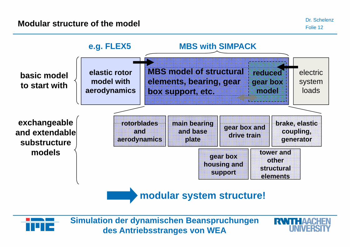
Dr. SchelenzFolie 12Modular structure of the model
MBS with SIMPACKe.g. FLEX5
MBS model of structural elements, bearing, gearbox support, etc.
elastic rotor model with
aerodynamics
reduced gear box
model
electricsystemloads
basic modelto start with
pp ,
main bearingrotorbladesexchangeable brake elasticmain bearing and base
plate
gear box and drive train
tower and
rotorblades and
aerodynamics
exchangeableand extendable
substructuremodels
brake, elastic coupling, generator
tower and other
structural elements
gear box housing and
support
models
modular system structure!
Simulation der dynamischen Beanspruchungendes Antriebsstranges von WEA
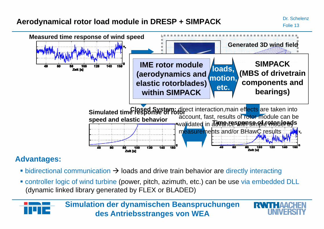
Dr. SchelenzFolie 13Aerodynamical rotor load module in DRESP + SIMPACK
Measured time response of wind speedGenerated 3D wind field
Measured time response of wind speed
IME t d l SIMPACK
Rotor module
IME rotor module(aerodynamics andelastic rotorblades)
SIMPACK(MBS of drivetraincomponents and
loads,motion,
etc
Simulated time response of rotor
within SIMPACK bearings)
Closed System: direct interaction,main effects are taken into t f t lt f t d l b
etc.
Time response of rotor loads p
speed and elastic behavior account, fast, results of rotor module can be validated in advance with simple model bymeasurements and/or BHawC results
Advantages:bidirectional communication loads and drive train behavior are directly interactingcontroller logic of wind turbine (power, pitch, azimuth, etc.) can be use via embedded DLL(dynamic linked library generated by FLEX or BLADED)
Simulation der dynamischen Beanspruchungendes Antriebsstranges von WEA
( y y g y )
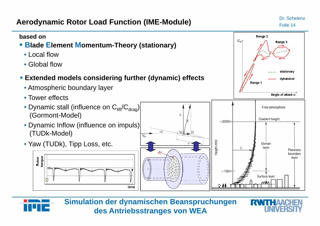
Dr. SchelenzFolie 14Aerodynamic Rotor Load Function (IME-Module)
based onbased onBlade Element Momentum-Theory (stationary)• Local flow
G f• Global flow
• Atmospheric boundary layerExtended models considering further (dynamic) effects• Atmospheric boundary layer
• Dynamic stall (influence on Clift/Cdrag) (G t M d l)
• Tower effects
(Gormont-Model)• Dynamic Inflow (influence on impuls)
(TUDk-Model)• Yaw (TUDk), Tipp Loss, etc.
Simulation der dynamischen Beanspruchungendes Antriebsstranges von WEA
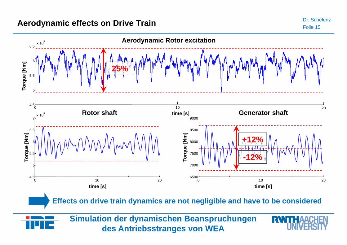
Dr. SchelenzFolie 15Aerodynamic effects on Drive Train
Aerodynamic Rotor excitation
6
6.5x 10⁵
m]
Aerodynamic Rotor excitation
25%
5
5.5
Torq
ue [N
m 25%
7x 10 Rotor shaft5
0 10 204.5
time [s]9000
Generator shaft
6
6.5
ue [N
m]
8000
8500
ue [N
m]
+12%
4.5
5
5.5
Torq
u
6500
7000
7500
Torq
u
-12%
0 10 204.5
time [s]0 10 20
6500
time [s]
Effects on drive train dynamics are not negligible and have to be considered
Simulation der dynamischen Beanspruchungendes Antriebsstranges von WEA
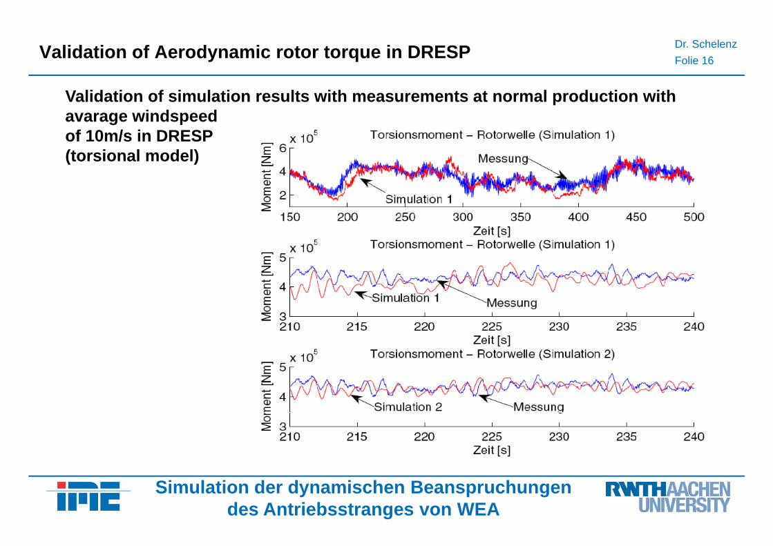
Dr. SchelenzFolie 16Validation of Aerodynamic rotor torque in DRESP
Validation of simulation results with measurements at normal production with avarage windspeed of 10m/s in DRESP (torsional model)
Simulation der dynamischen Beanspruchungendes Antriebsstranges von WEA
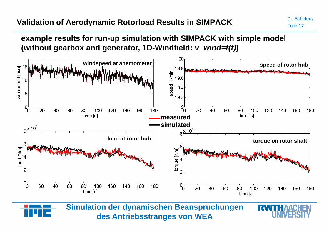
Dr. SchelenzFolie 17Validation of Aerodynamic Rotorload Results in SIMPACK
example results for run up simulation with SIMPACK with simple modelexample results for run-up simulation with SIMPACK with simple model(without gearbox and generator, 1D-Windfield: v_wind=f(t))
d f t h bwindspeed at anemometer speed of rotor hubwindspeed at anemometer
dmeasuredsimulated
load at rotor hub torque on rotor shafttorque on rotor shaft
Simulation der dynamischen Beanspruchungendes Antriebsstranges von WEA
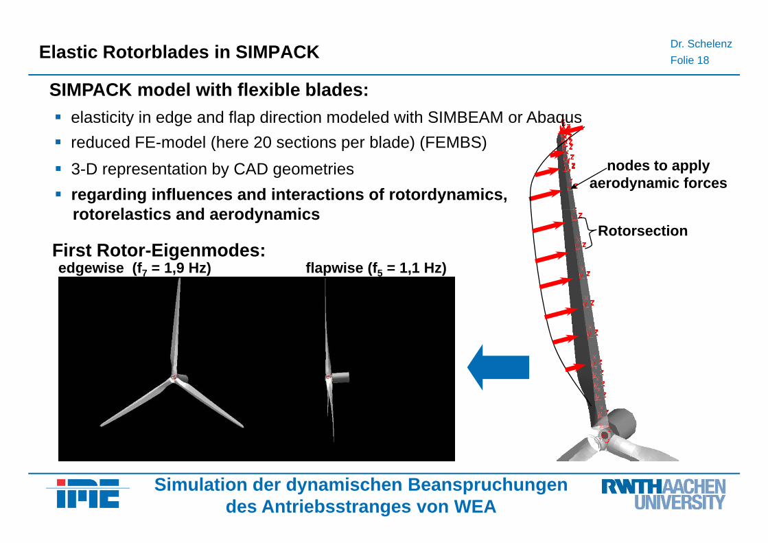
Dr. SchelenzFolie 18Elastic Rotorblades in SIMPACK
SIMPACK model with flexible blades:elasticity in edge and flap direction modeled with SIMBEAM or Abaqusreduced FE-model (here 20 sections per blade) (FEMBS)
SIMPACK model with flexible blades:
( p ) ( )
regarding influences and interactions of rotordynamics,t l ti d d i
nodes to applyaerodynamic forces
3-D representation by CAD geometries
rotorelastics and aerodynamics
First Rotor-Eigenmodes:edgewise (f7 = 1,9 Hz) flapwise (f5 = 1,1 Hz)
Rotorsection
edgewise (f7 1,9 Hz) flapwise (f5 1,1 Hz)
Simulation der dynamischen Beanspruchungendes Antriebsstranges von WEA
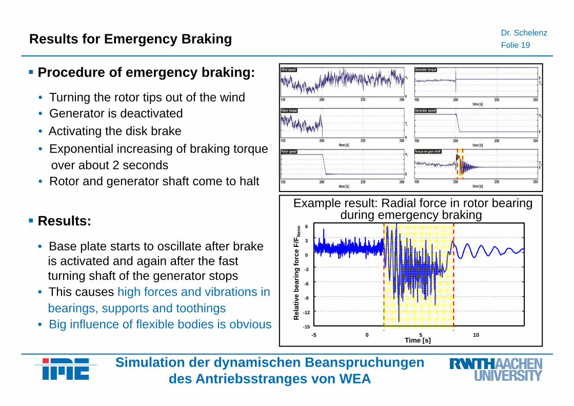
Dr. SchelenzFolie 19Results for Emergency Braking
Procedure of emergency braking:
• Turning the rotor tips out of the windGenerator is deacti ated• Generator is deactivated
• Activating the disk brake• Exponential increasing of braking torque
Example result: Radial force in rotor bearing
over about 2 seconds• Rotor and generator shaft come to halt
6
3
F/F
Nen
n
Example result: Radial force in rotor bearingduring emergency braking Results:
• Base plate starts to oscillate after brake0
-3
-6
e be
arin
g fo
rceBase plate starts to oscillate after brake
is activated and again after the fastturning shaft of the generator stops
• This causes high forces and vibrations in-9
-12
-15
-5 0 5 10Time [s]
Rel
ativ
eThis causes high forces and vibrations inbearings, supports and toothings
• Big influence of flexible bodies is obvious
Simulation der dynamischen Beanspruchungendes Antriebsstranges von WEA
Time [s]
Dr. SchelenzFolie 20Consumption
Interactions between all subsystems: Influences have to be and can be regarded by special written modules
Modular System structure: Substructure models can be exchanged and varied in detail
Model is extendable: More detailed models for bearings, gear boxes and electric systems can be easily embeddedsystems can be easily embedded
General analysis and parameter variations: E.g. possibility of analyzing other main shaft bearing concepts or gear box conceptsshaft bearing concepts or gear box concepts
Interfaces to other simulation tools: FLEX5, FEM-Software, MATLAB/Simulink, Postprocessing of loads, external loads given by wind turbine producer
Validation of main results: by measurement or other verified system results
Complete controller logic of wind turbine: allows realistic simulations of load cases andComplete controller logic of wind turbine: allows realistic simulations of load cases and producer know how is preserved in DLL (control of Pitch, Generator torque, etc.)
Model allows an insight: Non-measurable data and results can be generated
Simulation der dynamischen Beanspruchungendes Antriebsstranges von WEA
g g
Recommended