1
HCI-Conscious Software ArchitectureGregory D. Abowd, ProfessorSchool of Interactive Computing
Agenda
9:00-10:30 Intro to HCI and UI tools10:30-10:45 Break10:45-12:15 Usability and Software Architectures
(Part 1)12:15-1:15 Lunch1:15-2:45 Usability and Software Architectures
(Part 2)2:45-3:00 Break3:00-4:30 End-User Implications of Infrastructure4:30-5:00 Homework discussion
Introductions
Instructor
Gregory AY - bowd
HCI
Software Engineering
Ubiquitous Computing

2
What is HCI?
Human-Computer Interaction: The study of people and computing technology and the way they influence each other
The 3 U’s...
Utility (Usefulness), Usability, Ubiquity
Goals of this Course
• Introduction to history of implementation support for interactive systems– Dix, Finlay, Abowd & Beale (2004) Human-Computer Interaction.
Chapter 8.
• Usability Architectural Patterns: how to trace architectural impact of “usability modifications”– John, B. E., Bass, L. J., Sanchez-Segura, M-I. & Adams, R. J. (2004)
Bringing usability concerns to the design of software architecture. Proceedings of EHCI and the 11th International Workshop on Design, Specification and Verification of Interactive Systems, (Hamburg, Germany, July 11-13, 2004).
• End-user implications of middleware infrastructure– Edwards, W. K., Bellotti, V., Dey, A. K., and Newman, M. W. 2003. The
challenges of user-centered design and evaluation for infrastructure. In Proceedings of the CHI 2003 (Ft. Lauderdale, Florida, pp. 297-304.
History of UI Implementation Support
Programming tools provide layers of services for programmers
• windowing systems – core support for separate and simultaneous user-system activity
• programming the application and control of dialogue• interaction toolkits
– bring programming closer to level of user perception
• user interface management systems– controls relationship between presentation and functionality

3
Introduction
How does HCI affect the programmer?
Advances in coding have elevated programminghardware specific
→ interaction-technique specific
Layers of development tools– windowing systems– interaction toolkits– user interface management systems
Elements of windowing systems
Device independenceprogramming the abstract terminal device driversimage models for output and (partially) input
• pixels• PostScript (MacOS X, NextStep)• Graphical Kernel System (GKS)• Programmers' Hierarchical Interface to Graphics (PHIGS)
Resource sharingachieving simultaneity of user taskswindow system supports independent processesisolation of individual applications
roles of a windowing system

4
Architectures of windowing systems
three possible software architectures– all assume device driver is separate– differ in how multiple application management is implemented
1. each application manages all processes– everyone worries about synchronization– reduces portability of applications
2. management role within kernel of operating system– applications tied to operating system
3. management role as separate applicationmaximum portability
The client-server architecture
X Windows architecture

5
X Windows architecture (ctd)
• pixel imaging model with some pointing mechanism
• X protocol defines server-client communication
• separate window manager client enforces policies for input/output:– how to change input focus
– tiled vs. overlapping windows
– inter-client data transfer
Programming the application
read-evaluation loop
repeatread-event(myevent)case myevent.type
type_1:do type_1 processing
type_2:do type_2 processing
...type_n:
do type_n processingend case
end repeat
Programming the application
notification-basedvoid main(String[] args) {
Menu menu = new Menu();menu.setOption(“Save”);menu.setOption(“Quit”);menu.setAction(“Save”,mySave)menu.setAction(“Quit”,myQuit)
...}
int mySave(Event e) {// save the current file
}
int myQuit(Event e) {// close down
}
6
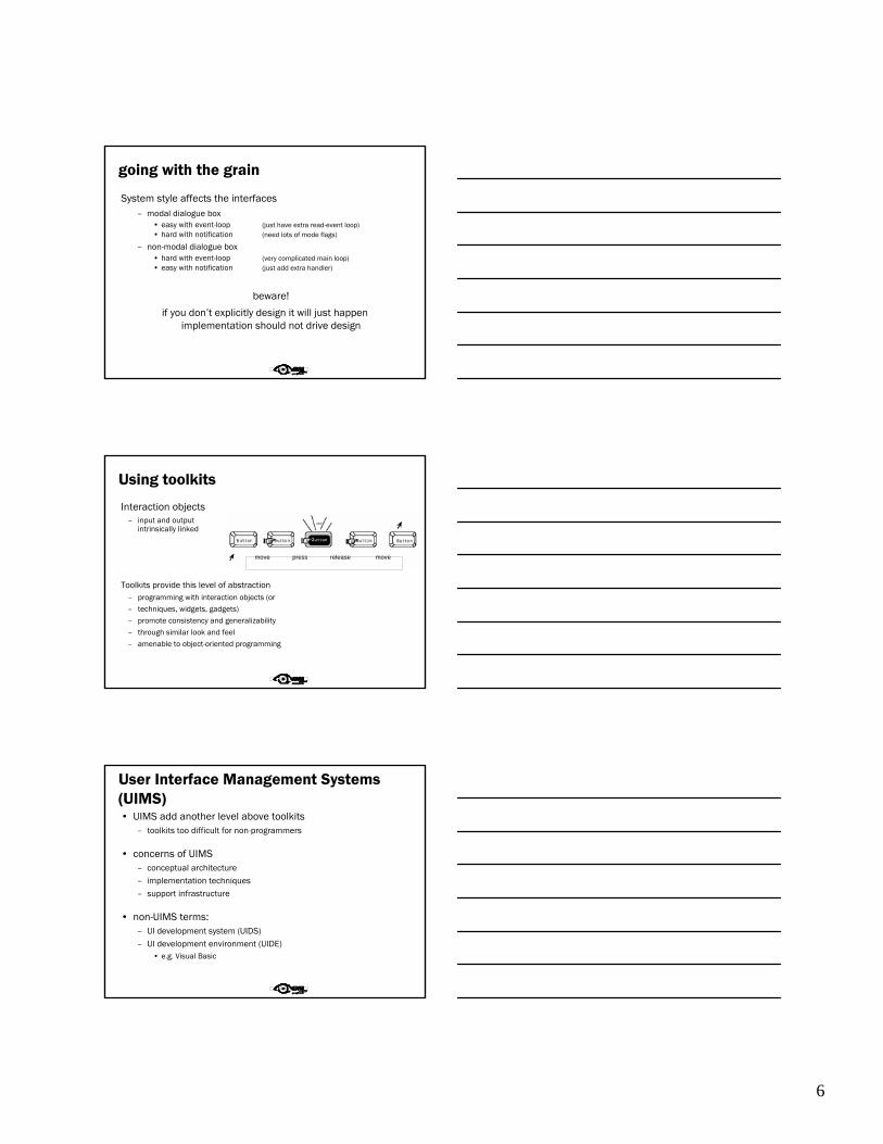
going with the grain
System style affects the interfaces– modal dialogue box
• easy with event-loop (just have extra read-event loop)• hard with notification (need lots of mode flags)
– non-modal dialogue box• hard with event-loop (very complicated main loop)• easy with notification (just add extra handler)
beware!
if you don’t explicitly design it will just happen implementation should not drive design
Using toolkits
Interaction objects– input and output
intrinsically linked
Toolkits provide this level of abstraction– programming with interaction objects (or– techniques, widgets, gadgets)– promote consistency and generalizability– through similar look and feel– amenable to object-oriented programming
move press release move
User Interface Management Systems (UIMS)• UIMS add another level above toolkits
– toolkits too difficult for non-programmers
• concerns of UIMS– conceptual architecture– implementation techniques– support infrastructure
• non-UIMS terms:– UI development system (UIDS)– UI development environment (UIDE)
• e.g. Visual Basic
7
UIMS as conceptual architecture
• separation between application semantics and presentation
• improves:– portability – runs on different systems
– reusability – components reused cutting costs
– multiple interfaces – accessing same functionality
– customizability – by designer and user
UIMS tradition – interface layers / logical components
• linguistic: lexical/syntactic/semantic
• Seeheim:
• Arch/Slinky
presentation dialogue application
dialogue
lexical
physicalfunctional
core
func. core adaptor
Seeheim model
Presentation DialogueControl
Functionality(applicationinterface)
USERUSER APPLICATION
switch
lexical syntactic semantic

8
conceptual vs. implementation
Seeheim– arose out of implementation experience
– but principal contribution is conceptual
– concepts part of ‘normal’ UI language
… because of Seeheim …… we think differently!
e.g. the lower box, the switch
• needed for implementation• but not conceptual
presentation dialogue application
semantic feedback
• different kinds of feedback:– lexical – movement of mouse
– syntactic – menu highlights
– semantic – sum of numbers changes
• semantic feedback often slower– use rapid lexical/syntactic feedback
• but may need rapid semantic feedback– freehand drawing
– highlight trash can or folder when file dragged
what’s this?
USER
Lexical Syntactic Semantic
APPLICATIONApplication
InterfaceModel
DialogueControlPresentation

9
the bypass/switch
USER
Lexical Syntactic Semantic
APPLICATIONApplication
InterfaceModel
DialogueControlPresentation
rapid semantic feedback
direct communicationbetween application
and presentation
but regulated bydialogue control
Arch/Slinky
• more layers! – distinguishes lexical/physical
• like a ‘slinky’ spring different layers may be thicker (more important) in different systems
• or in different components
dialogue
lexical
physicalfunctional
core
func. core adaptor
monolithic vs. components
• Seeheim has big components
• often easier to use smaller ones– esp. if using object-oriented toolkits
• Smalltalk used MVC – model–view–controller– model – internal logical state of component
– view – how it is rendered on screen
– controller – processes user input

10
MVCmodel - view - controller
model
view
controller
MVC issues
• MVC is largely pipeline model: input → control → model → view → output
• but in graphical interface– input only has meaning in relation to output
e.g. mouse click– need to know what was clicked
– controller has to decide what to do with click
– but view knows what is shown where!
• in practice controller ‘talks’ to view– separation not complete
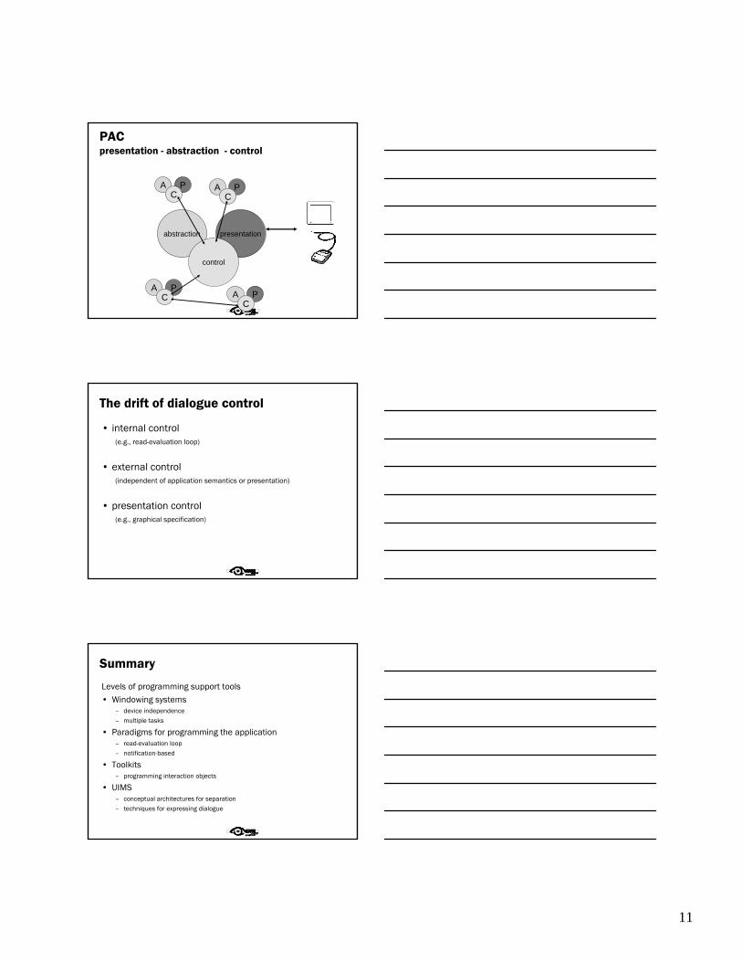
PAC model
• PAC model closer to Seeheim– abstraction – logical state of component– presentation – manages input and output– control – mediates between them
• manages hierarchy and multiple views– control part of PAC objects communicate
• PAC cleaner in many ways …but MVC used more in practice (e.g. Java Swing)
11
PACpresentation - abstraction - control
abstraction presentation
control
A PC
A PC
A PC A P
C
The drift of dialogue control
• internal control(e.g., read-evaluation loop)
• external control(independent of application semantics or presentation)
• presentation control(e.g., graphical specification)
Summary
Levels of programming support tools• Windowing systems
– device independence– multiple tasks
• Paradigms for programming the application– read-evaluation loop– notification-based
• Toolkits– programming interaction objects
• UIMS– conceptual architectures for separation– techniques for expressing dialogue

12
Agenda
9:00-10:30 Intro to HCI and UI tools10:30-10:45 Break10:45-12:15 Usability and Software Architectures
(Part 1)12:15-1:15 Lunch1:15-2:45 Usability and Software Architectures
(Part 2)2:45-3:00 Break3:00-4:30 End-User Implications of Infrastructure4:30-5:00 Homework discussion
Source
These materials adapted from Usability and Software Architecture research at Carnegie Mellon School of Computer Science & Software Engineering Institutehttp://www.cs.cmu.edu/~bej/usa/index.html
Specifically, tutorials on Usability-Supporting Architectural Patterns by Bonnie John, Len Bass, Natalia Juristo and Maribel Sanchez-Segura

6 USAP Tutorial ICSE2004
USAP Tutorial ICSE 2004 - page 6
Tutorial objectives: The sceneThe usability analyses or user test data are in; the
development team is poised to respond. The software had been carefully modularized so that modifications to the UI
would be fast and easy. When the usability problems are presented, someone around the table exclaims, “Oh, no,
we can’t change THAT!”
7 USAP Tutorial ICSE2004
USAP Tutorial ICSE 2004 - page 7
Tutorial objectives: The sceneThe usability analyses or user test data are in; the
development team is poised to respond. The software had been carefully modularized so that modifications to the UI
would be fast and easy. When the usability problems are presented, someone around the table exclaims, “Oh, no,
we can’t change THAT!”
The requested modification, feature, functionality, reaches
too far in to the architecture of the system to allow
economically viable and timely changes to be made.
• Even when the functionality is right,
• Even when the UI is separated from that functionality,
• Architectural decisions made early in development can
preclude the implementation of a usable system.
8 USAP Tutorial ICSE2004
USAP Tutorial ICSE 2004 - page 8
Tutorial objectives:
• Understand basic principles of software architecture for interactive systems and its relationship to the usability of
that system• Be able to evaluate whether common usability scenarios
will arise in the systems you are developing and what implications these usability scenarios have for software
architecture design
• Understand patterns of software architecture that facilitate usability, and recognize architectural decisions
that preclude usability of the end-product, so that you can effectively bring usability considerations into early
architectural design.
9 USAP Tutorial ICSE2004
USAP Tutorial ICSE 2004 - page 9
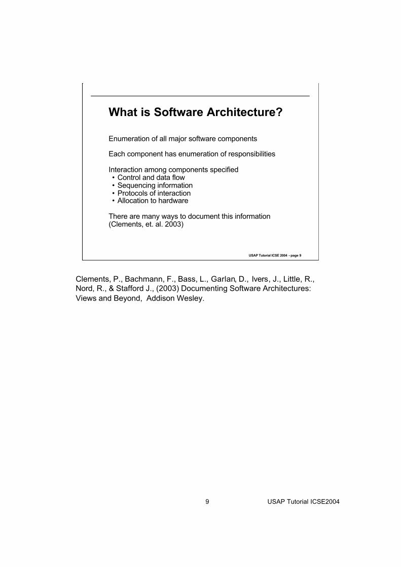
What is Software Architecture?
Enumeration of all major software components
Each component has enumeration of responsibilities
Interaction among components specified• Control and data flow• Sequencing information• Protocols of interaction• Allocation to hardware
There are many ways to document this information (Clements, et. al. 2003)
Clements, P., Bachmann, F., Bass, L., Garlan, D., Ivers, J., Little, R.,
Nord, R., & Stafford J., (2003) Documenting Software Architectures:
Views and Beyond, Addison Wesley.

10 USAP Tutorial ICSE2004
USAP Tutorial ICSE 2004 - page 10
Purposes of Software ArchitectureCommunication among stakeholders • An educational purpose
• A managerial purpose
Artifact for analysis• Embeds early design decisions
Set of blueprints for implementation
11 USAP Tutorial ICSE2004
USAP Tutorial ICSE 2004 - page 11
What does usability mean?
As many definitions as there are authors!
What’s important depends on context of use
Some commonly-seen aspects• efficiency of use• time to learn to use efficiently• support for exploration and problem-solving• user satisfaction (e.g., trust, pleasure, acceptance by
discretionary users)
Our concern is which of these can be influenced by architectural decisions

12 USAP Tutorial ICSE2004
USAP Tutorial ICSE 2004 - page 12
A usability benefits hierarchy
Increases individual user effectiveness• Expedites routine performance
- Accelerates error-free portion of routine performance- Reduces the impact of routine user errors (slips)
• Improves non-routine performance- Supports problem-solving- Facilitates learning
• Reduces the impact of user errors caused by lack of knowledge (mistakes)- Prevents mistakes- Accommodates mistakes
Reduces the impact of system errors• Prevents system errors• Tolerates system errors
Increases user confidence and comfort

13 USAP Tutorial ICSE2004
USAP Tutorial ICSE 2004 - page 13
Activities in software development
System Test and Deployment
Implementation
Detailed Design
Architecture Design
Requirements
System Formulation

14 USAP Tutorial ICSE2004
USAP Tutorial ICSE 2004 - page 14
Activities in software development + HCI techniques
System Test and Deployment - HCI techniques:
User testing in the field, Log analysis, etc.
Implementation - HCI techniques:
UI Toolkits
Detailed Design - HCI techniques:
Heuristic Evaluation, Cognitive Walkthrough, GOMS, PICTIVE,
Rapid prototyping+user testing, etc.
Architecture Design - HCI techniques:
What we’ll learn today
Requirements - HCI techniques:
Interviewing, questionnaires, Contextual Inquiry
System Formulation - HCI techniques:
Interviewing, questionnaires, Contextual Inquiry

15 USAP Tutorial ICSE2004
USAP Tutorial ICSE 2004 - page 15
Detailed Design - CommonPractice for Interactive Systems
System Test and Deployment - HCI techniques:
Think-aloud Usability Testing, Log analysis, etc.
Implementation - HCI techniques:
UI Toolkits
Detailed Design - HCI techniques:
Heuristic Evaluation, Cognitive Walkthrough, GOMS, PICTIVE,
Rapid prototyping+user testing, etc.
Architecture Design - HCI techniques:
What we’ll learn today
Requirements - HCI techniques:
Interviewing, questionnaires, Contextual Inquiry
System Formulation - HCI techniques:
Interviewing, questionnaires, Contextual Inquiry

16 USAP Tutorial ICSE2004
USAP Tutorial ICSE 2004 - page 16
Detailed Design - CommonPractice for Interactive SystemsThe HCI techniques supporting detailed design of the user interface are all based on iterative design
• i.e.,design, test (analyze or measure), change, and re-test.
Once software has been designed, iteration implies
change.
Software engineers plan for change through isolating
section to be changed (separation).
In detailed design, the items to be separated are those
relating to presentation, input, possibly dialog.

17 USAP Tutorial ICSE2004
USAP Tutorial ICSE 2004 - page 17
Separation Based Architectural Patterns for Usability
Presentation-Abstraction-Control (PAC)• Developed in 1980s by group at the University of
Grenoble• Reaction to shortcomings of Smalltalk Model-View-
Controller (MVC)
J2EE Model-View-Controller (J2EE MVC)
• Developed by Sun to support J2EE• Adaptation of Smalltalk MVC to web environment
Separation based patterns are commonly used in practice
and have proven quite successful
PAC is documented in:
Buschmann, F., Meuneir, R, Rohnert, H., Sommerlad, P. and Stal, M.,
(1996) Pattern-Oriented Software Architecture, A System of Patterns,
Chichester, Eng: John Wiley and Sons.
J2EE-MVC is documented at http://java.sun.com/blueprints/patterns/MVC-
detailed.html

18 USAP Tutorial ICSE2004
USAP Tutorial ICSE 2004 - page 18
Presentation-Abstraction-Control(PAC)Hierarchical series of agents• Top-level agent provides functional core• Bottom level agents are self contained semantic concepts such
as spread sheets or forms.• Intermediate level agents act as intermediaries between top level
and bottom level agents and determines which bottom level agents are active.
Each agent has three portions:• Presentation - Input/output manager (unlikely to occur
except in bottom level)• Abstraction - Application functionality• Control - Mediator between Presentation & Abstraction
and communicator to controls at other levels

19 USAP Tutorial ICSE2004
USAP Tutorial ICSE 2004 - page 19
Outputdevice
Input device
Presentation-Abstraction-Control (PAC)
AbstractionPresentation
ControllerFunctional Core
(presentation
unlikely)
Intermediaries
(presentation
unlikely)
Self contained semanticconcepts
AbstractionPresentation
Controller
AbstractionPresentation
Controller
AbstractionPresentation
Controller
AbstractionPresentation
Controller
20 USAP Tutorial ICSE2004
USAP Tutorial ICSE 2004 - page 20
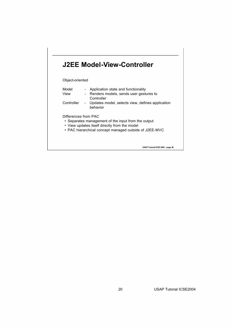
J2EE Model-View-Controller
Object-oriented
Model - Application state and functionality
View - Renders models, sends user gestures to
Controller
Controller - Updates model, selects view, defines application
behavior
Differences from PAC
• Separates management of the input from the output
• View updates itself directly from the model
• PAC hierarchical concept managed outside of J2EE-MVC

21 USAP Tutorial ICSE2004
USAP Tutorial ICSE 2004 - page 21
J2EE Model-View-Controller
Outputdevice
Input device
CommandProcessor
CommandProcessor
ModelCommand
Processor
CommandProcessor
View
CommandProcessor
Command
Processor
Controller

22 USAP Tutorial ICSE2004
USAP Tutorial ICSE 2004 - page 22
Software architectural patternsPAC and J2EE MVC are “software architectural patterns” (Buschmann, et. al., 1996)
Independent of application
Provides some indication of assignment of responsibilities to components
Much left unspecified:• Allocation to processes• Synchronous/asynchronous communication• Decomposition of components• Class structure• Other responsibilities of components• Exceptions
Sufficient to give overall guidance for design approach
Buschmann, F., Meuneir, R, Rohnert, H., Sommerlad, P. and Stal, M.,
(1996) Pattern-Oriented Software Architecture, A System of Patterns,
Chichester, Eng: John Wiley and Sons.

23 USAP Tutorial ICSE2004
USAP Tutorial ICSE 2004 - page 23
Software architectural patterns - 2
Patterns community has a variety of styles and levels of detail for writing about patterns
• Buschmann, et. al., (1996) provide prose descriptions, architecture-level diagrams, and sample code.
• Gamma, et. al., (1995) provide prose descriptions, class diagrams, and code samples
• Hillside Group advocates mainly prose and emphasizes
pattern languages above individual patterns
Buschmann, F., Meuneir, R, Rohnert, H., Sommerlad, P. and Stal, M.,
(1996) Pattern-Oriented Software Architecture, A System of Patterns,
Chichester, Eng: John Wiley and Sons.
Gamma, E., Helm, R., Johnson, R., Vlissides, J. (1995). Design Patterns.
Boston, Massachusetts: Addison-Wesley.
Information about the Hillside Group and patterns and pattern languages can
be found at http://www.hillside.net/

24 USAP Tutorial ICSE2004
USAP Tutorial ICSE 2004 - page 24
Why separation-basedarchitectural patterns are not sufficient for interactive systems
Remember iterative design?

25 USAP Tutorial ICSE2004
USAP Tutorial ICSE 2004 - page 25
How does J2EE MVC support iterative design?Change color of font• Modify only View
- View contains all display logic; font changes only require modifying the display
Change order of dialogs
• Modify only Controller
- Controller defines the presentation flow, so changing dialog order involves modifying the controller logic

26 USAP Tutorial ICSE2004
USAP Tutorial ICSE 2004 - page 26
What happens to other usability changes?Add the ability to cancel a long-running command• Requires modification of all three modules
- View – must have cancel button or other means for user to specify cancel
- Controller – logic to respond to the View’s menu selection and execute the appropriate Model function
- Model – free allocated resources, etc.

27 USAP Tutorial ICSE2004
USAP Tutorial ICSE 2004 - page 27
Shortcomings of separation patterns for solving the “We can’t change THAT!” problem With respect to adding the ability to cancel
• Involved all components
• Not much localization
• If requirement for cancel discovered late, then will require extensive modification to the architecture.

29 USAP Tutorial ICSE2004
USAP Tutorial ICSE 2004 - page 29
Beyond separation-basedarchitectural patterns Our goal is to provide software designers and usability specialist tools to recognize and prevent common usability problems that are not supported by separation.
We are doing this by:• Identifying those aspects of usability that are
“architecturally sensitive” and embodying them in small scenarios
• Providing a way to reason about the forces acting on architecture design in these scenarios
• Providing checklist of important software responsibilities and possible architecture patterns to satisfy these scenarios

30 USAP Tutorial ICSE2004
USAP Tutorial ICSE 2004 - page 30
What does architecturally-sensitive mean?A scenario is architecturally-sensitive if it is difficult to add the scenario to a system after the architecture has been designed.
Solution may:• Insure that multiple components interact in particular
ways• Insure that related information and actions can be found
in a single component and easily changed
Separation patterns intended to localize changes to presentation. Therefore,• Changing color of font – NOT architecturally-sensitive• Adding cancellation – IS architecturally-sensitive

31 USAP Tutorial ICSE2004
USAP Tutorial ICSE 2004 - page 31
An architecturally-sensitive scenario:Canceling commands
The user issues a command then changes his or her mind, wanting to stop the operation and return the software to its
pre-operation state. It doesn’t matter why the user wants to stop; he or she could have made a mistake, the system
could be unresponsive, or the environment could have
changed.

32 USAP Tutorial ICSE2004
USAP Tutorial ICSE 2004 - page 32
What other architecturally-sensitive scenarios can you think of?

33 USAP Tutorial ICSE2004
USAP Tutorial ICSE 2004 - page 33
Here are some others we have thought ofAggregating DataAggregating Commands AlertCanceling Commands Checking for CorrectnessEvaluating the SystemForm/Field ValidationHistory LoggingMaintaining Device Independence
(Different Access Methods)Maintaining Compatibility with
Other SystemsMaking Views AccessibleModifying InterfacesNavigating Within a Single ViewObserving System StateOperating Consistently Across
ViewsProviding Good Help
(Context-Sensitive Help)Predicting Task DurationRecovering from Failure
Reusing InformationRetrieving Forgotten PasswordsShortcutsStatus indicationSupporting Comprehensive
SearchingSupporting International Use
(Different Languages)Supporting Multiple ActivitiesSupporting Personalization
(User Profile)Supporting Undo Supporting VisualizationTourUsing Applications Concurrently
(Multi-Tasking)Verifying Resources WizardWorkflow modelWorking at the User’s Pace Working in an Unfamiliar Context
This list of architecturally-sensitive usability scnearios is compiled from
Bass, L., John, B. E., & Kates, J. (2001). Achieving usability through
software architecture (CMU/SEI-2001-TR-005). Pittsburgh, PA:
Software Engineering Institute.
http://www.sei.cmu.edu/publications/documents/01.re
ports/01tr005.html
And
Juristo , N., Moreno, A. M., & Sanchez, M. (2003) Deliverable D.3.4.
Techniques, patterns and styles for architecture- level usability improvement. -
ESPRIT project (IST-2001-32298)
http://www.ls.fi.upm.es/status/results/deliverables.html
34 USAP Tutorial ICSE2004
USAP Tutorial ICSE 2004 - page 34
Need more than just architecturally sensitive scenario
Architecturally sensitive scenarios are potential requirements for a particular system to support usability
Need
• to determine whether the benefit of supporting the scenario outweighs the cost
• to provide guidance to the development team as to the
issues associated with implementing a solution

35 USAP Tutorial ICSE2004
USAP Tutorial ICSE 2004 - page 35
User’s Organizational Setting
Task in an Environment
System
Forces
Forces
Ben
efi
ts
Systems exist in a context

36 USAP Tutorial ICSE2004
USAP Tutorial ICSE 2004 - page 36
Context for computer system
Computer systems fulfill “business” goals• “Business goals” could be mission, academic,
entertainment, etc.• User using the system creates certain benefits for the
“organization” that created it• Creating system has costs.
Cost/Benefit• Implementation support for total scenario• Implementation support for pieces of the scenario
But more detail is necessary to be able to understand cost/benefit and implications of implementation

37 USAP Tutorial ICSE2004
USAP Tutorial ICSE 2004 - page 37
User«s Organizational Settings
Task in an Environment
Forces
System
Users
Human
desires and
capabilities
Software
Benefits
realized
when the solution is
provided
State of the
software
General
responsibilities
Specific Solution (more
detail): e.g., architecture,
software tactics
Forces
Forces
Forces
Previous
design
decisions
ForcesBenefits
Forces acting on architecture design

38 USAP Tutorial ICSE2004
USAP Tutorial ICSE 2004 - page 38
Reasoning about architecture designDiffering forces motivate particular aspects of solution.
Forces come from three sources:• Task and environment in which user is operating.
- E.g., Cancel is only useful if operation is long running.• Human desires and capabilities.
- E.g., User makes mistakes, Cancel allows one type of
correction of mistake.• State of the software.
- E.g., Networks fail. Giving the user the ability to cancel may prevent the user from being blocked
because of this failure.

39 USAP Tutorial ICSE2004
USAP Tutorial ICSE 2004 - page 39
Architecture Design
Many different methods for satisfying a particular scenario.
Most systems use separation based architectural pattern as a basis for overall design of system.
We provide two different solutions:
• General solution – responsibilities of the software that
must be fulfilled by any solution• Specific solution. An architectural pattern that shows how
to implement the general solution in the context of a separation based pattern. For example, we’ll assume
J2EE-MVC as an overarching separation based pattern.

40 USAP Tutorial ICSE2004
USAP Tutorial ICSE 2004 - page 40
Software Architectural Patterns
We have given you two examples of architectural patterns (PAC and J2EE-MVC)
These are examples of the solution portion of an
architectural pattern
The patterns community has developed a set of common
concepts that should be included in descriptions of a pattern.
We embody these concepts in Usability-Supporting
Architectural Patterns (USAPs)

41 USAP Tutorial ICSE2004
USAP Tutorial ICSE 2004 - page 41
Usability-Supporting Architectural Patterns - 1
Context• Situation – architecturally sensitive usability scenarios
• Conditions – constraints on when the situation is relevant• Usability benefits – enumeration of benefits to the user
from supporting this scenario
Problem - Forces in conflict
• Forces exerted by the task and environment• Forces exerted by human desires and capabilities
• Forces exerted by the state of the software when the user wishes to apply the architecturally sensitive usability
scenario

42 USAP Tutorial ICSE2004
USAP Tutorial ICSE 2004 - page 42
Usability-Supporting Architectural Patterns - 2
General solution – set of responsibilities that any solution to situation must satisfy
Specific solution – architectural pattern to solve situation
assuming an overarching separation based pattern• In our slides, we’ll assume J2EE-MVC

43 USAP Tutorial ICSE2004
USAP Tutorial ICSE 2004 - page 43
USAP Context template
Potential Usability Benefits: A brief description of the benefits to
the user if the solution is implemented. We use the usability benefit
hierarchy given earlier
Conditions on the Situation: Any conditions on the situation
constraining when the pattern is useful
Situation: A brief description of the situation from the user’s
perspective that makes this pattern useful

44 USAP Tutorial ICSE2004
USAP Tutorial ICSE 2004 - page 44
USAP Context for Cancel - 1
Conditions on the Situation: A user is working in a system where
the software has long-running commands, i.e., more than one
second.
The cancellation command could be explicitly issued by the user,
or through some sensing of the environment (e.g., a child’s hand in
a power car window).
Situation: The user issues a command then changes his or her
mind, wanting to stop the operation and return the software to its
pre-operation state. It doesn’t matter why the user wants to stop;
he or she could have made a mistake, the system could be
unresponsive, or the environment could have changed.

45 USAP Tutorial ICSE2004
USAP Tutorial ICSE 2004 - page 45
Benefits of Cancel - 1
Potential Usability Benefits:
A. Increases individual user effectiveness
A.1 Expedites routine performance
A.1.2 Reduces the impact of routine user errors (slips) by
allowing users to revoke accidental commands and return to
their task faster than waiting for the erroneous command to
complete.
A.2 Improves non-routine performance
A.2.1 Supports problem-solving by allowing users to apply
commands and explore without fear, because they can
always abort their actions.
46 USAP Tutorial ICSE2004
USAP Tutorial ICSE 2004 - page 46
Benefits of Cancel – 2
Potential Usability Benefits:
A. Increases individual user effectiveness
A.3 Reduces the impact of user errors caused by lack of
knowledge (mistakes)
A.3.2 Accommodates mistakes by allowing users to abort
commands they invoke through lack of knowledge and
return to their task faster than waiting for the erroneous
command to complete.
B. Reduces the impact of system errors
B.2 Tolerates system errors by allowing users to abort
commands that aren’t working properly (for example, a user
cancels a download because the network is jammed).
C.Increases user confidence and comfort by allowing users to
perform without fear because they can always abort their
actions.

47 USAP Tutorial ICSE2004
USAP Tutorial ICSE 2004 - page 47
Cost/Benefit
There is a cost to implementing cancel. The software engineer can calculate this.
There is a benefit to the organization (as we explained) from implementing cancel.• Benefit to current user immediately from recovered time• Benefit to current user later from cleaning up local
resources so system will not subsequently crash• Benefit to other users from cleaning up shared
resources.
Development team (or project manager) can do cost/benefit analysis to determine whether to implement cancel.

48 USAP Tutorial ICSE2004
USAP Tutorial ICSE 2004 - page 48
First row of problem/general solution template always scenario
The first row provides the rationale for the scenario in terms of the forces.
This enables the development team to decide whether to
implement the scenario at all.
It may be that forces are not applicable to current
development.
It may also be that forces cause consideration of scenario when it may be have been overlooked.

49 USAP Tutorial ICSE2004
USAP Tutorial ICSE 2004 - page 49
USAP Problem/General Solution Template
Responsibilities
of the general
solution that
resolve the forces
in the row.
Forces
exerted by
the state of
the software .
Each row
contains a
different force.
Forces
exerted by
human
desires and
capabilities.
Each row
contains a
different
force.
Forces
exerted by the
environment
and the task.
Each row
contains a
different force
General
SolutionProblem

50 USAP Tutorial ICSE2004
USAP Tutorial ICSE 2004 - page 50
Cancel Problem/General Solution:Responsibility R1 is essentially the scenario itself
R1.
Must provide
a means to
cancel a
command
Software is
sometimes
unresponsive
Users slip or
make mistakes,
or explore
commands and
then change
their minds, but
do not want to
wait for the
command to
complete.
Networks are
sometimes
unresponsive.
Sometimes
changes in the
environment
require the
system to
terminate.
General
SolutionProblem

51 USAP Tutorial ICSE2004
USAP Tutorial ICSE 2004 - page 51
Template Problem/General Solution -other rows
Each subsequent row of the problem general solution template provides rationale for one or more responsibilities.
Usually one row per responsibility, but sometimes rationale
for multiple responsibilities are the same and so multiple responsibilities are included in one row.
Allows development team to understand reason for responsibility and make cost/benefit decisions about:
• Necessity• Utility

52 USAP Tutorial ICSE2004
USAP Tutorial ICSE 2004 - page 52
Cancel Problem/General Solution: Responsibility R2
R2.
Provide a button,
menu item,
keyboard shortcut
and/or other means
to cancel the active
command.
Software
has to
receive an
action from
the user to
do
something
Users have to
communicate
their intentions
to the software
through overt
acts (e.g., finger
movements)
General SolutionProblem

53 USAP Tutorial ICSE2004
USAP Tutorial ICSE 2004 - page 53
Cancel Problem/General Solution: Responsibilities R3 and R4
R3.
Must always listen for the
cancel command or
environmental changes
R4.
Must be always gathering
information (state, resource
usage, actions, etc.) that
allow for recovery of the
state of the system prior to
the execution of the current
command
No one can
predict when the
users will want to
cancel
commands
No one can
predict when
the
environment
will change
General SolutionProblem

54 USAP Tutorial ICSE2004
USAP Tutorial ICSE 2004 - page 54
Appendix contains the full table of forces and general responsibilities for canceling commands.
• We have enumerated 21 responsibilities• Some are conditional
- on aspects of the task - or state of the software

55 USAP Tutorial ICSE2004
USAP Tutorial ICSE 2004 - page 55
Summary of responsibilities that any implementation of cancel must consider
R1. Must provide a means to cancel a commandR2. Provide a button, menu item, keyboard shortcut and/or other
means to cancel the active command.R3. Must always listen for the cancel command or environmental
changesR4. Must always gather information (state, resource usage,
actions, etc.) that allow for recovery of the state of the systemprior to the execution of the current command
R5. Must acknowledge receipt of the cancellation command appropriately within 150 msec. The acknowledgement must be appropriate to the manner in which the command was issued. For example, if the user pressed a cancel button, changing the color of the button will be seen. If the user used a keyboard shortcut, flashing the menu that contains that command might be appropriate.
… to R21 (see Tutorial Notes)
Either the command itself is responsive
R6. The command must have the ability to cancel itself (I.e., it must fulfill
Responsibilities R10 to R21 (e.g., an object-oriented system would have a
cancel method in each object)
Or the command itself is not responsive
R7. An active portion of the application must ask the infrastructure to cancel the
command, or
R8. The infrastructure itself must provide a means to request the cancellation of
the application (e.g., task manager on Windows, force quit on MacOS)
R9. If either R7 or R8, then the infrastructure must have the ability to cancel the
active command (I.e., it must fulfill Responsibilities R10 to R21)
If the command has invoked collaborating processes
R10. The collaborating processes have to be informed of the cancellation of the
invoking command (these processes have their own responsibilities that they
must perform in response to this information, possibly treat it as a
cancellation.). The information given to collaborating processes may include
the request for cancellation, the progress of cancellation, and/or the
completion of cancellation.

56 USAP Tutorial ICSE2004
Continuation of responsibilities that any implementation of cancel
must consider
Either the system is capable of rolling back all changes to the state prior to execution
of the command.
R11. Restore the system back to its state prior to execution of the command.
Or the system is not capable of rolling back all changes to the state prior to execution
of the command.
R12. Restore the system back to as close to the state prior to execution of the
command as possible
R13. Inform the user of the difference between the prior state and the restored
state.
Either all resource can be restored
R14. Resources must be freed
Or some resources has been irrevocably consumed and cannot be restored
R15. Inform the user of the partially-restored resources in a manner that they will
see it.
For critical tasks with incomplete state or resource restoration,
R16. Require acknowledgement from the user that they are aware of the partially-
restored nature of the cancellation.
R17. Return control to the user, or not, depending on the forces from the task
R18. If control cannot be returned to the user, inform the user of this fact (and
ideally, why that is the case)
R19. Estimate the time it will take to cancel within 20%
R20. Inform the user of this estimate.
· If the estimate is between 1 and 10 seconds, changing the cursor shape is sufficient.
· If the estimate is more than 10 seconds, and time estimate is with 20%, then a
progress indicator is better.
· If estimate is more than 10 seconds but cannot be estimated accurately, consider
other alternatives (see TN, footnote 8)
R21. Once the cancellation has finished the system must provide feedback to the
user that cancellation is finished, e.g., if cursor was changed to busy indicator,
change it back to normal; if progress bar was displayed was displayed,
remove it; if dialog box was provided, close it.

57 USAP Tutorial ICSE2004
USAP Tutorial ICSE 2004 - page 57
Observations on general responsibilities
Many details might be overlooked by implementer• Free resources
• Provide feedback if not able to completely cancel• Inform collaborators
Table provides rationale which enables cost/benefit
possibilities. e.g. “return control to the user immediately”
• Benefit is that user wants to multi-task – increasedefficiency
• Cost may be too high depending on system environment.
60 USAP Tutorial ICSE2004
USAP Tutorial ICSE 2004 - page 60
Overarching patterns
Designers do not build system design around desire for architecturally sensitive usability scenarios.
Designers have some overarching pattern that they use.e.g. PAC or J2EE-MVC
This overarching pattern introduces additional software forces on specific solution.
Consider “inform collaborating processes” responsibility when canceling web-based data base application.
Notice the difference in communication from PAC to J2EE-MVC

61 USAP Tutorial ICSE2004
USAP Tutorial ICSE 2004 - page 61
Outputdevice
Input device
Presentation-Abstraction-Control (PAC)
Abstraction
Controller
Data base manager
Web browser
AbstractionPresentation
Controller
Abstraction
Controller
Abstraction
Controller
AbstractionPresentation
Controller
“Cancel”
“Cancel active command”
“Halt current transaction and roll back”

62 USAP Tutorial ICSE2004
USAP Tutorial ICSE 2004 - page 62
J2EE MVC version of “inform collaborators”
Outputdevice
Input device
CommandProcessor
CommandProcessor
ModelCommand
Processor
CommandProcessor
View
CommandProcessor
Command
Processor
Controller
“Cancel
buttonpushed”
“Cancel”
No communication among collaborators shown
“Cancel”

63 USAP Tutorial ICSE2004
USAP Tutorial ICSE 2004 - page 63
We’ll use J2EE-MVC as overarching pattern to illustrate our USAPs
Overarching pattern will affect specific solution in our USAPs
We’ll use J2EE-MVC as overarching pattern because it is
widely used in web applications.
Open question as to how, in general, choice of a different
overarching pattern would affect specific solutions
64 USAP Tutorial ICSE2004
USAP Tutorial ICSE 2004 - page 64
We’ll use a non-critical task for the exampleThis implies that• The user can have control while the cancellation is
happening• The user need not acknowledge the results of the
cancellation

65 USAP Tutorial ICSE2004
USAP Tutorial ICSE 2004 - page 65
Specific Solution
Architectural view: Presentation of one (or more) aspects of the architecture.
Common views:
• Component Diagram – shows major units of software but does not show dynamic behavior or assignment of units
to various processors.
• Sequence Diagram – shows sequence of activities for a single thread through the system

66 USAP Tutorial ICSE2004
USAP Tutorial ICSE 2004 - page 66
Context of the specific solution: J2EE-MVC
:Controller
:View Active-
Command:Model
:Controller:Controller
:View:View Active-
Command:Model
Active-
Command:Model

67 USAP Tutorial ICSE2004
USAP Tutorial ICSE 2004 - page 67
Component diagram for a specific solution to Cancel
Prior-State-
Manager:Model
:Controller
Cancellation-Manager
:Model
Listener:Controller
:View Active-
Command:Model
Collaborating-
Process:Model
Prior-State-
Manager:Model
Prior-State-
Manager:Model
:Controller:Controller
Cancellation-Manager
:Model
Cancellation-Manager
:Model
Listener:ControllerListener:Controller
:View:View Active-
Command:Model
Active-
Command:Model
Collaborating-
Process:Model
Collaborating-
Process:Model
68 USAP Tutorial ICSE2004
USAP Tutorial ICSE 2004 - page 68
Responsibilities of new component –Listener
• Type Controller• Must always listen for the cancel command or
environmental changes (R3)

69 USAP Tutorial ICSE2004
USAP Tutorial ICSE 2004 - page 69
Responsibilities of new component –Cancellation Manager
• Type Model• Always listen and gather information (R3, R4)
• If the Active Command is not responding, handle the cancellation (R7, R10, R11, R12)
• Free resources (R14)• Estimate time to cancel (R19)
• Inform the user of Progress of the cancellation (R13,
R15, R20, R21)
Full text of responsibilities assigned to the Cancellation Manager in this example solution
R3. Must always listen for the cancel command or environmental changes
R4. Must always gather information (state, resource usage, actions, etc.) that allow for
recovery of the state of the system prior to the execution of the current command
R7. An active portion of the application must ask the infrastructure to cancel the command,
If R7, then R10. The collaborating processes have to be informed of the cancellation of the
invoking command (these processes have their own responsibilities that they must
perform in response to this information, possibly treat it as a cancellation.). The
information given to collaborating processes may include the request for cancellation,
the progress of cancellation, and/or the completion of cancellation.
If R7, then R11. Restore the system back to its state prior to execution of the command. OR
R12. Restore the system back to as close to the state prior to execution of the command
as possible
If R12, then R13. Inform the user of the difference between the prior state and the restored
state.
R14. All resources that can be freed must be freed.
If any resources are not capable of being freed, then R15. Inform the user of the partially-
restored resources in a manner that they will see it.
R19. Estimate the time it will take to cancel within 20%
R20. Inform the user of this estimate.
R21. Once the cancellation has finished the system must provide feedback to the user that
cancellation is finished, e.g., if cursor was changed to busy indicator, change it back to
normal; if progress bar was displayed was displayed, remove it; if dialog box was
provided, close it.

70 USAP Tutorial ICSE2004
USAP Tutorial ICSE 2004 - page 70
Responsibilities of new component –Prior State Manager
• Type Model
• Must always gather information (state, resource usage, actions, etc.) that allow for recovery of the state of the
system prior to the execution of the current command (R4)
• If the Active Command is not responding (R7), work with
the Cancellation Manager to restore the system back to its state prior to execution of the command (R11) or as
close as possible to that state (R12)

71 USAP Tutorial ICSE2004
USAP Tutorial ICSE 2004 - page 71
New responsibilities for old components - View
• Type View• Provide a button, menu item, keyboard shortcut and/or
other means to cancel the active command (R2)• Must always listen for the cancel command or
environmental changes (R3)• Provide feedback to the user about the progress of the
cancellation (R5, R13, R15, R20, R21)
Full text of responsibilities assigned to the View in this examp le solution
R2. Provide a button, menu item, keyboard shortcut and/or other means to cancel the active
command
R3. Must always listen for the cancel command or environmental changes
R5. Must acknowledge receipt of the cancellation command appropriately within 150 msec.
If any module did R12, then R13. Inform the user of the difference between the prior state and
the restored state.
If any module did R14, then R15. Inform the user of the partially -restored resources in a
manner that they will see it.
R20. Inform the user of the time estimate.
R21. Once the cancellation has finished the system must provide feedback to the user that
cancellation is finished, e.g., if cursor was changed to busy indicator, change it back to
normal; if progress bar was displayed was displayed, remove it; if dialog box was
provided, close it.

72 USAP Tutorial ICSE2004
USAP Tutorial ICSE 2004 - page 72
New responsibilities for old components - Active Command• Type Model
• Always gather information (R4)
• Handle the cancellation by terminating processes, and
restoring state and resources (R6, R10, R11, R12, R14)
• Provide appropriate feedback to the user (R13, R15, R19,
R20, R21)
Full text of responsibilities assigned to the Active Command in this example solution
R4. Must always gather information (state, resource usage, actions, etc.) that allow for
recovery of the state of the system prior to the execution of the current command
R6. The command must respond by canceling itself (I.e., it must fulfill Responsibilities R10 to
R21 (e.g., an object-oriented system would have a cancel method in each object)
If R6 then R10. The collaborating processes have to be informed of the cancellation of the
invoking command (these processes have their own responsibilities that they must
perform in response to this information, possibly treat it as a cancellation.). The
information given to collaborating processes may include the request for cancellation,
the progress of cancellation, and/or the completion of cancellation.
If R6, then R11. Restore the system back to its state prior to execution of the command. Or
R12. Restore the system back to as close to the state prior to execution of the command
as possible
If R12, then R13. Inform the user of the difference between the prior state and the restored
state.
R14. Resources that can be freedmust be freed
If any resources are not capable of being freed, then R15. Inform the user of the partially-
restored resources in a manner that they will see it.
R19. Estimate the time it will take to cancel within 20%
R20. Inform the user of this estimate.
R21. Once the cancellation has finished the system must provide feedback to the user that
cancellation is finished, e.g., if cursor was changed to busy indicator, change it back to
normal; if progress bar was displayed was displayed, remove it; if dialog box was
provided, close it.

73 USAP Tutorial ICSE2004
USAP Tutorial ICSE 2004 - page 73
Responsibilities not assigned or shown in our diagrams and why.• We are not considering a “critical task” where the
progress and results of the cancellation must effect user
behavior, therefore R16 and R18 are not assigned.• J2EE-MVC implicitly returns control to the user during
cancellation, so R17is not assigned.• Our diagram does not show the infrastructure in which
the application runs, therefore responsibilities assigned
to the infrastructure are not shown (R8, R9)
List of responsibilities not assigned to our components or not shown in the diagrams.
R8. The infrastructure itself must provide a means to request the cancellation of the application (e.g., task manager on Windows, force quit on MacOS)
R9. If either R7 or R8, then the infrastructure must have the ability to cancel the active
command (I.e., it must fulfill Responsibilities R10 to R21)
R16 Require acknowledgement from the user that they are aware of the partially-
restored nature of the cancellation. (we’re not doing a “critical task” in this example)
R17. Return control to the user, or not, depending on the forces from the task (implicit
in J2EE-MVC)
R18. If control cannot be returned to the user, inform the user of this fact (and ideally,
why that is the case) (we’re not doing a “critical task” in this example)

74 USAP Tutorial ICSE2004
USAP Tutorial ICSE 2004 - page 74
:View
Sequence diagram of activities prior to issuing cancel command
:Controller Active-
Command:Model
Prior-State-
Manager:Model
Cancellation-
Manager:Model
:User
normal
operation
invokeregister (R4)
save current state (R4)
normal
operation
Xxx put in note about the components that don’t show up in this sequence
75 USAP Tutorial ICSE2004
USAP Tutorial ICSE 2004 - page 75
command (R5)
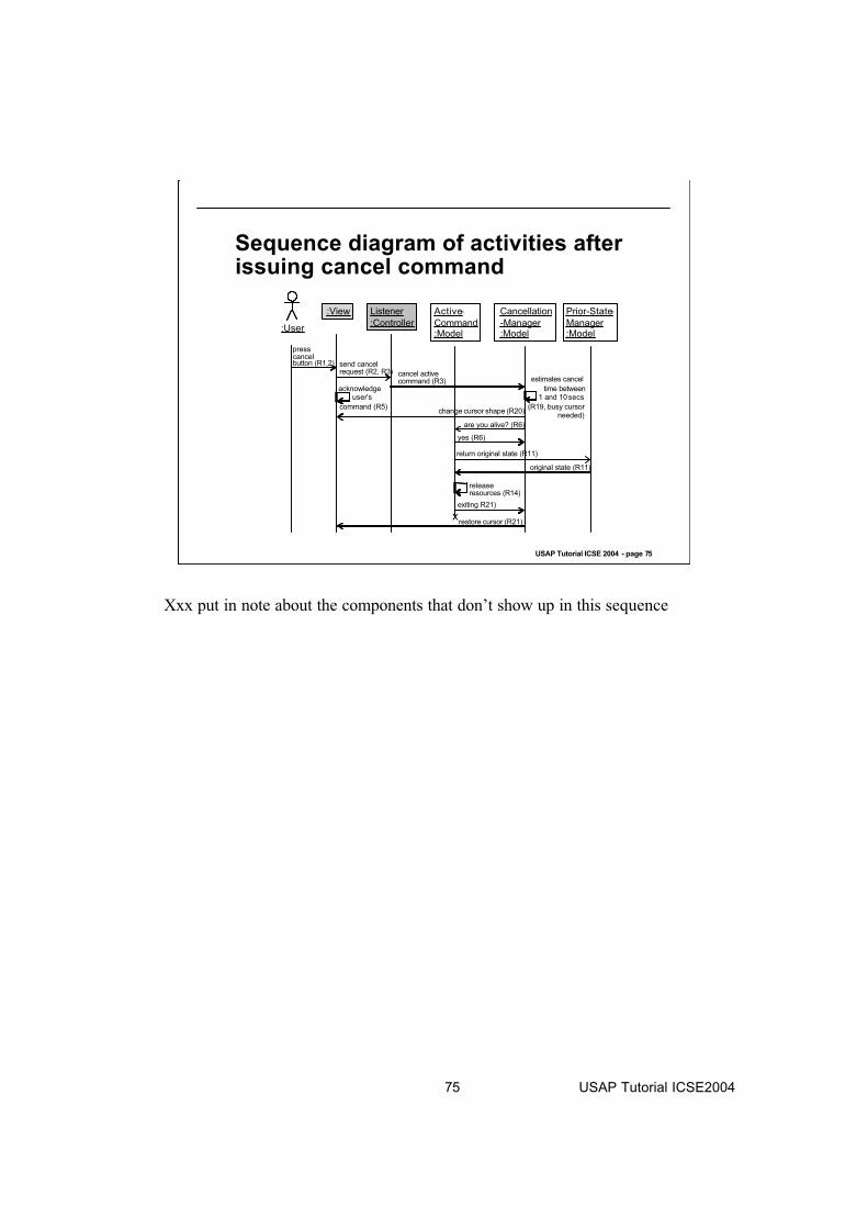
:View Listener
:Controller
Active-
Command:Model
Prior-State-
Manager:Model
Cancellation
-Manager:Model
presscancelbutton (R1,2) send cancel
request (R2, R3) cancel activecommand (R3)
change cursor shape (R20)
acknowledgeuser’s
estimates cancel
time between1 and 10 secs
(R19, busy cursor needed)
are you alive? (R6)
yes (R6)
return original state (R11)
original state (R11)
releaseresources (R14)
exiting R21)
xrestore cursor (R21)
:User
Sequence diagram of activities after issuing cancel command
Xxx put in note about the components that don’t show up in this sequence

76 USAP Tutorial ICSE2004
USAP Tutorial ICSE 2004 - page 76
Comment on sequence diagrams
Important portion of cancel is that listener is on separate thread of control (otherwise listener may be blocked
because command is not responding and command owns the active thread).
Sequence diagram does not make this explicit. It is implicit
in fact that listener responds regardless of state of active
command.
Sequence diagram is UML (standard). Difficult to show threads in UML.

80 USAP Tutorial ICSE2004
USAP Tutorial ICSE 2004 - page 80
A Second USAP
Observing System State

81 USAP Tutorial ICSE2004
USAP Tutorial ICSE 2004 - page 81
Types of Feedback
Observing System state: To inform users of the internal system state and state changes.
Progress indicator: To inform users that the system is processing an action that will take some time to complete.
Interaction Feedback: To inform users that the system has registered a user interaction, that is, that the system has heard users.
Warning: To inform users of any irreversible action.
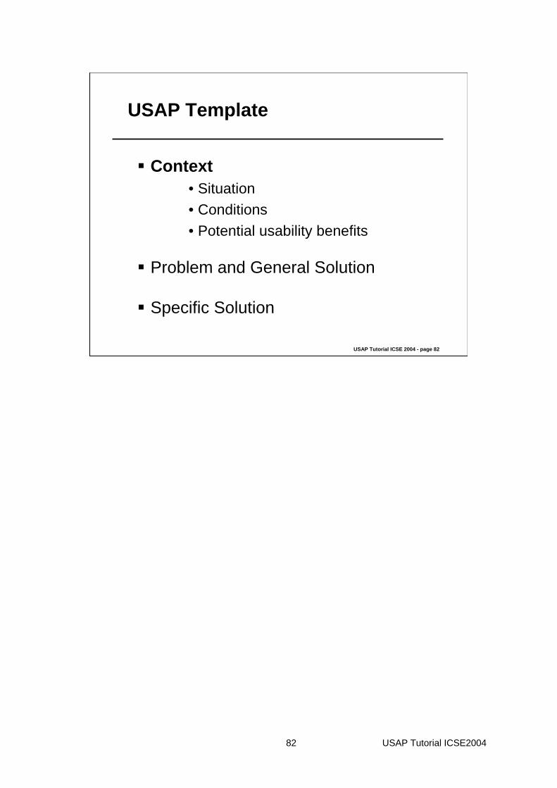
82 USAP Tutorial ICSE2004
USAP Tutorial ICSE 2004 - page 82
USAP Template
Context• Situation• Conditions• Potential usability benefits
Problem and General Solution
Specific Solution
83 USAP Tutorial ICSE2004
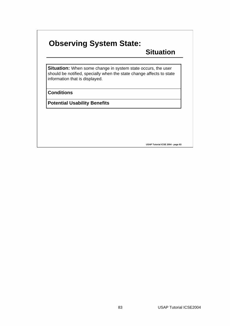
USAP Tutorial ICSE 2004 - page 83
Observing System State:Situation
Potential Usability Benefits
Conditions
Situation: When some change in system state occurs, the user should be notified, specially when the state change affects to state information that is displayed.

84 USAP Tutorial ICSE2004
USAP Tutorial ICSE 2004 - page 84
Observing System State:Conditions
Potential Usability Benefits
Conditions: • A user may not be given the system state data necessary to operate the system (e.g., uninformative error messages, no file size given for folders). • The system state may be given in a way that violates human tolerances (e.g., displayed too quickly for people to read). • The system state may also be given unclearly, thereby confusing the user. • System designers should account for human needs and capabilities when deciding what aspects of a system state to display and how to do so.
Situation: When some change in system state occurs, the user should be notified.
85 USAP Tutorial ICSE2004
USAP Tutorial ICSE 2004 - page 85
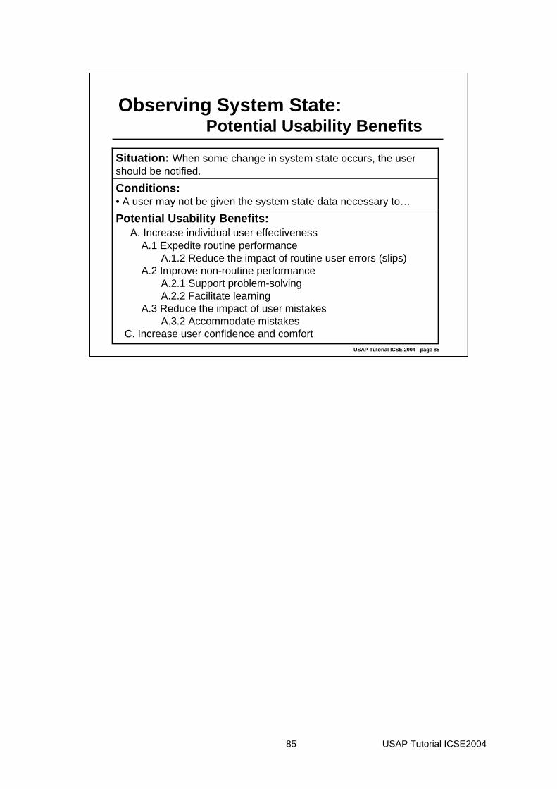
Observing System State:Potential Usability Benefits
Potential Usability Benefits:A. Increase individual user effectiveness
A.1 Expedite routine performanceA.1.2 Reduce the impact of routine user errors (slips)
A.2 Improve non-routine performanceA.2.1 Support problem-solvingA.2.2 Facilitate learning
A.3 Reduce the impact of user mistakesA.3.2 Accommodate mistakes
C. Increase user confidence and comfort
Conditions: • A user may not be given the system state data necessary to…
Situation: When some change in system state occurs, the user should be notified.

86 USAP Tutorial ICSE2004
USAP Tutorial ICSE 2004 - page 86
USAP Template
Context
Problem and General Solution
Specific Solution

87 USAP Tutorial ICSE2004
USAP Tutorial ICSE 2004 - page 87
USAP Template
Context
Problem and General Solution• Forces exerted by the environment and the task
• Forces exerted by human desires and capabilities
• Forces exerted by the state of the software
• Responsibilities of the general solution that resolve the forces
Specific Solution

88 USAP Tutorial ICSE2004
USAP Tutorial ICSE 2004 - page 88
Observing System State:Human Forces (1/2)
1. When some change in system state occurs, the user should be notified (HF01)
2. If the system fails, the user should be notified(HF02)
3. Users need to be alerted of the fact that a command does not respond (HF03)

89 USAP Tutorial ICSE2004
USAP Tutorial ICSE 2004 - page 89
Observing System State:Environmental Forces
1. Resources, be it the network, a database, etc., can become not operational (EF01)

90 USAP Tutorial ICSE2004
USAP Tutorial ICSE 2004 - page 90
Observing System State:System Forces (1/2)
1. System state changes (SF01)
2. Systems sometimes fail (SF02)
3. Commands sometimes die (SF03)

91 USAP Tutorial ICSE2004
USAP Tutorial ICSE 2004 - page 91
Observing System State:Problem - Responsibilities
Responsibilities of thesoftware system thatresolve the forces
Forcesexerted by the state ofthe software
Forcesexerted by human desires andcapabilities
Forcesexerted by theenvironmentand the task
General SolutionProblem

92 USAP Tutorial ICSE2004
USAP Tutorial ICSE 2004 - page 92
Observing System State:Problem - Responsibilities
Problem/Forces:
SF01. The software changes
HF01. When some change in system state occurs, the user should be notified.
Solution/Responsibilities:
R01. The software should be able to listen to active commands, because they can provide information about the state of the system. If this information is useful to the user, the system should be able to provide this information to the user in the appropriate manner and in the proper location.

93 USAP Tutorial ICSE2004
USAP Tutorial ICSE 2004 - page 93
Observing System State:Problem - Responsibilities
Problem/Forces:
SF03. Commands sometimes fail to be operational
HF02: If the system fails, the user should be notified
HF03: To alert users of the fact that a command does not respond
Solution/Responsibilities:
R02: As active commands can fail, the software system should be able to check at any time whether a given command is being executed and, if the command fails, inform users that the command is not operational.

94 USAP Tutorial ICSE2004
USAP Tutorial ICSE 2004 - page 94
Observing System State:Problem - Responsibilities
Problem/Forces:
EF1: Resources, be it the network, a database, etc., can become not operational
Solution/Responsibilities:
R03: The software should be able to listen to or query external resources, like networks or databases, about their state, to inform properly the user if any resource is not performing properly.

95 USAP Tutorial ICSE2004
USAP Tutorial ICSE 2004 - page 95
Observing System State:Problem - Responsibilities
Problem/Forces:
HF01. When some change in system state occurs, the user should be notified.
Solution/Responsibilities:
R04: The software should be able to check the system resources and inform the user about their use.

96 USAP Tutorial ICSE2004
USAP Tutorial ICSE 2004 - page 96
USAP Template
Context
Problem and General Solution
Specific Solution• General responsibilities• Forces exerted by previous design decisions • Allocation of responsibilities to specific components• Rationale

97 USAP Tutorial ICSE2004
USAP Tutorial ICSE 2004 - page 97
Observing System State:General Responsibilities
R01: Listen to active commandsR02: Ascertain the state of active commandsR03: Listen to or query external sourcesR04: Check the state of system resources

98 USAP Tutorial ICSE2004
USAP Tutorial ICSE 2004 - page 98
Observing System State:Forces from design decisions
Architectural styles for the system will affect specific solution
We have used J2EE-MVC as an architectural style for designing a specific solution
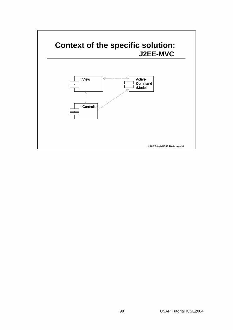
99 USAP Tutorial ICSE2004
USAP Tutorial ICSE 2004 - page 99
Context of the specific solution:J2EE-MVC
:Controller
:View Active-Command:Model
:Controller:Controller
:View:View Active-Command:Model
Active-Command:Model

100 USAP Tutorial ICSE2004
USAP Tutorial ICSE 2004 - page 100
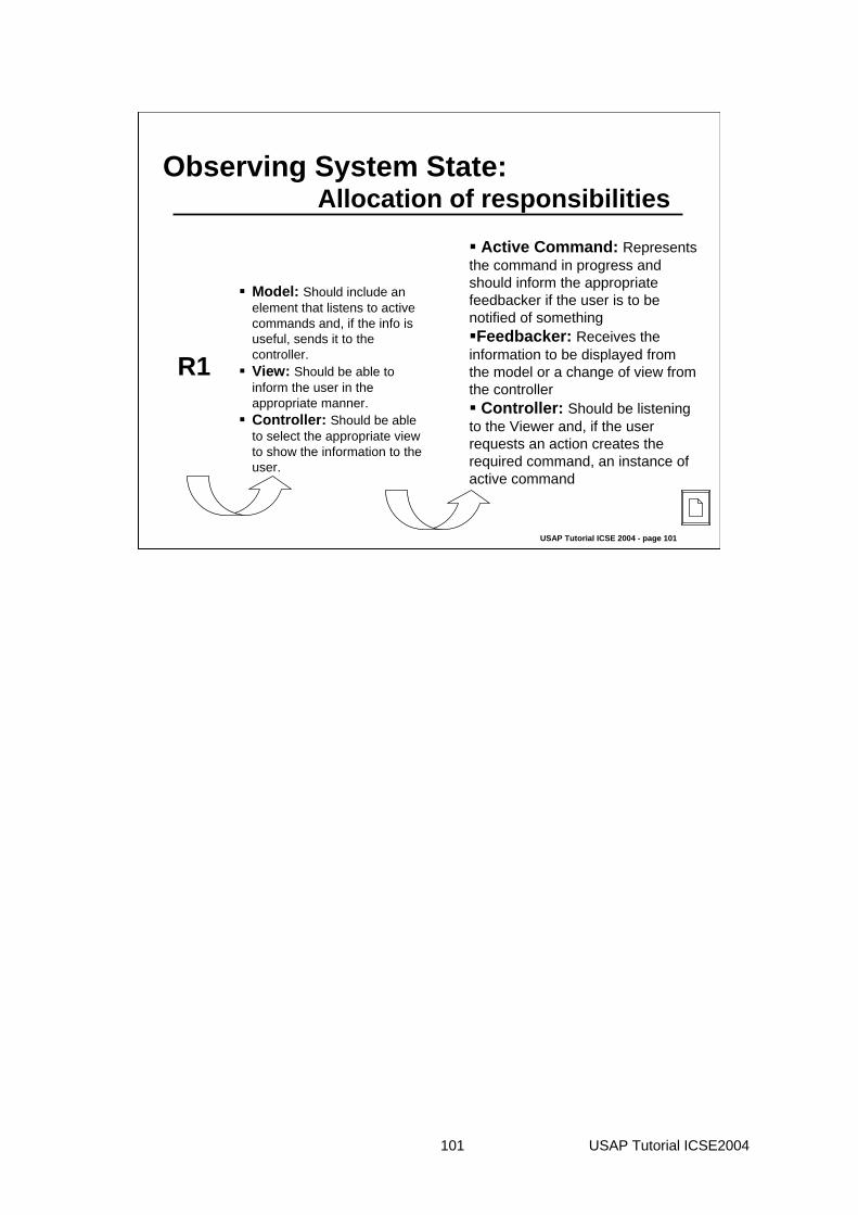
Observing System State:Allocation of responsibilities
R1. The software should be able to listen to active commands. If this information is useful to the user, the system should be able to provide this information to the user in the appropriate manner not only through the display.
Model: Should include an element that listens to active commands and, if the info is useful, sends it to the controller.View: Should be able to inform the user in the appropriate manner.Controller: Should be able to select the appropriate view to show the information to the user.
101 USAP Tutorial ICSE2004
USAP Tutorial ICSE 2004 - page 101
Observing System State:Allocation of responsibilities
R1
Model: Should include an element that listens to active commands and, if the info is useful, sends it to the controller.View: Should be able to inform the user in the appropriate manner.Controller: Should be able to select the appropriate view to show the information to the user.
Active Command: Represents the command in progress and should inform the appropriate feedbacker if the user is to be notified of somethingFeedbacker: Receives the
information to be displayed from the model or a change of view from the controller
Controller: Should be listening to the Viewer and, if the user requests an action creates the required command, an instance of active command

102 USAP Tutorial ICSE2004
USAP Tutorial ICSE 2004 - page 102
Observing System State:Allocation of responsibilities
Controller: Should be listening to the Viewer and, if the user requests an action creates the required command, an instance of active command
Controller: Should be able to select the appropriate view to show the information to the user.
Feedbacker: Receives the information to be displayed from the model or a change of view from the controller
View: Should be able to inform the user in the appropriate manner.
Active command: Represents the command in progress and should inform appropriate feedbacker if the user is to be notified of something
Model: The model should include an element that listens to active commands and, if the information is useful, sends the information to be passed on to the user (see model decomposition)
R01:The software should be able to listen to active commands, because they can provide information about the state of the system. If this information is useful to the user, the system should be able to provide this information to the user in the appropriate manner and in the appropriate location, not only through the display.
Allocation of responsibilities to specific components
Forces exerted by previous design decisions
General Responsibilities of the software

103 USAP Tutorial ICSE2004
USAP Tutorial ICSE 2004 - page 103
Observing System State:Specific Solution
Check whether or not the ongoing command is dead.
Check whether or not external resources are dead.
Check whether or not the system has enough resources to execute the ongoing command.

104 USAP Tutorial ICSE2004
USAP Tutorial ICSE 2004 - page 104
Observing System State:Specific Solution
Active Command:model
:View
:Controller
105 USAP Tutorial ICSE2004
USAP Tutorial ICSE 2004 - page 105
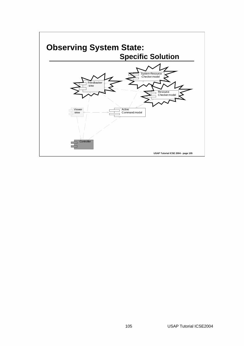
Observing System State:Specific Solution
Viewer:view
Feedbacker:view
Active Command:model
Resource Checker:model
System-Resource-Checker:model
:Controller

106 USAP Tutorial ICSE2004
USAP Tutorial ICSE 2004 - page 106
Observing System State:Responsibilities of new components
Must be able to check whether or not the system can provide enough resources to properly execute the ongoing command (R04)
System Resource Checker
(Type Model)
Must be able to check whether or not the ongoing command is alive (R02)Must be able to check whether or not the external resources are alive (R03)
Resource Checker(Type Model)
Receive info from Resource Checker and select the appropriate feedback (R02, R03, R04)
Feedbacker(Type Model)
RESPONSIBILITIESNEW COMPONENT

107 USAP Tutorial ICSE2004
USAP Tutorial ICSE 2004 - page 107
Observing System State:Specific Solution
Viewer:view
Feedbacker:view
Active Command:model
Resource Checker:model
System-Resource-Checker:model
:Controller

108 USAP Tutorial ICSE2004
USAP Tutorial ICSE 2004 - page 108
Observing System State:Responsibilities of old components
Must always listen for the viewer requests to create the respective active command.
Controller(Type Controller)
Represents the command in progress and should inform the Feedbacker about any change produced.
Active Command(Type Model)
Must be able to gather user requests.Viewer(Type View)
RESPONSABILITIESOLD COMPONENT

109 USAP Tutorial ICSE2004
USAP Tutorial ICSE 2004 - page 109
Observing System State:Responsibilities related to control
The Active Command should run in a different thread from the Resource Checker component
The Active Command should run in a different thread from the System Resource Checker component

110 USAP Tutorial ICSE2004
USAP Tutorial ICSE 2004 - page 110
Observing System State:Specific Solution
Imagine we are faced with a situation where:
The ongoing command is dead

111 USAP Tutorial ICSE2004
USAP Tutorial ICSE 2004 - page 111
Observing System State:Specific Solution
: Feedbacker: view
: User
: Viewer:view
: Controller : Active-Command: model : ResourceChecker:model
(EI02) Action( )(3) Action( )
(4) CreateCommand()
IP02 CheckCriticity( )
(IP01) CalculateElapsedTime( )
(IP03) CheckKindOfOperat ion()
(7) AreYouAliv e( )
(1) Feedback (ongoing command dead)
112 USAP Tutorial ICSE2004
USAP Tutorial ICSE 2004 - page 112
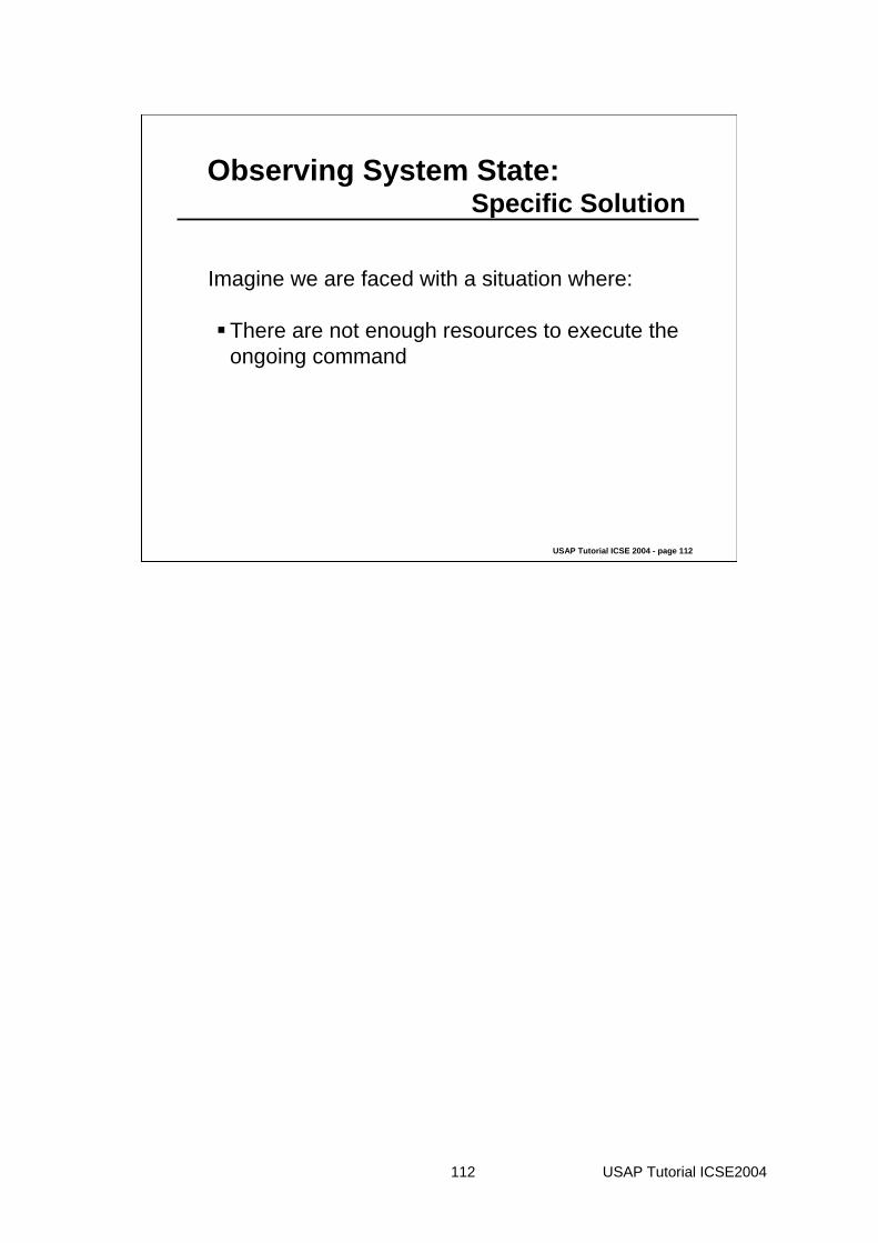
Observing System State:Specific Solution
Imagine we are faced with a situation where:
There are not enough resources to execute the ongoing command

113 USAP Tutorial ICSE2004
USAP Tutorial ICSE 2004 - page 113
Observing System State:Specific Solution
: Feedbacker: v iew
: User
: Viewer:v iew
: Controller : Activ e-Command: model : Systrem-Resource-Checker:model
(EI02) Action( )(3) Action( )
(4) CreateCommand()
(IR01) CheckSystemResouces(
(1) Feedback(close-the-sy stem)

114 USAP Tutorial ICSE2004
USAP Tutorial ICSE 2004 - page 114
Observing System State:Specific Solution
Imagine we are faced with a situation where:
The external resources are performing properly
115 USAP Tutorial ICSE2004
USAP Tutorial ICSE 2004 - page 115
Observing System State:Specific Solution
: Feedbacker: view
: User
: Viewer:view
: Controller : Active-Command: model
: External-Resouce
: ResourceChecker:model
IP01 and 1 U ntil end of operat ion
(EI02) Action( )(3) Action( )
(4) CreateCommand()
IP02 CheckCri ti city( )
(IP01) CalculateElapsedTime( )
(IP03) CheckKindOfOperation()
(1) Feedback(Kind-of-feedback, information)
(1) Feedback (end-of-operation)
(ER01) CheckExternalResources()
(ER02) ExternalResourceAv ailable()

118 USAP Tutorial ICSE2004
USAP Tutorial ICSE 2004 - page 118
Tutorial Summary
Software architectural design can support iterative design through separation based patterns, but some usability issues are difficult to resolve through iterative design.
Architecturally sensitive scenarios are examples of problems that are difficult to implement once architecture is designed.
USAPs are an attempt to capture some of these problems, provide rationale to support cost/benefit analysis, provide general set of responsibilities for any solution, and provide sample specific solution to further guide software designer.
Currently have about two dozen architecturally sensitive scenarios and are in process of turning these into USAPs.

1
Agenda
9:00-10:30 Intro to HCI and UI tools10:30-10:45 Break10:45-12:15 Usability and Software Architectures
(Part 1)12:15-1:15 Lunch1:15-2:45 Usability and Software Architectures
(Part 2)2:45-3:00 Break3:00-4:30 End-User Implications of Infrastructure4:30-5:00 Homework discussion
Stuck in the Middle
How do you evaluate the worthiness of infrastructure (e.g., middleware, architecture, toolkit)?
Recall example of read-eval loop versus notification-based programming for interactive dialogue.
Let’s look at a detailed example of an infrastructure/toolkit and then explore the evaluation question.
Context-Aware Computing
Effective use of context is the key to a ubicompenvironment that does the right thing.
Supporting the right abstractions and services for handling context makes it easier to design, build and evolve context-aware applications.

2
The Importance of Context
• What is context?– any information that can be used to characterize the
situation of an entity
– emphasis on implicit context, that applications do not have access to
• C-A research is slowed by difficulty of development
Why are C-A Applications Hard to Build?
Cyberguide case study: no separation of concerns
Separation of Concerns
• Acquisition• Representation• Storage• Distribution• Reaction

3
Inspiration
• Analogy to GUI toolkits
• What is the context equivalent to the GUI widget or interactor?
The Context Toolkit
• Simplify application’s view of world
Application Application
Widget
Sensor
Widget
Sensor
Widget
Sensor
XML over HTTP
Flexible Representation
Widget
Sensor
Widget
Application Application
Interpreter Interpreter
Sensor

4
Focus on Entities
Widget
Sensor
Widget
Application
InterpreterAggregator
Sensor
Focus on Context, not Source
Widgets
Applications
Interpreters Aggregators
DiscovererWe provide
We desire
Widget
Sensor
Widget
Application Application
Interpreter InterpreterAggregator
Sensor
ContextArchitecture
Evaluating the CTK
So, how do we determine if CTK is a good solution to developing context-aware applications?
Look at apps it can be used to develop.

5
Applications
• In/Out Board and Context-Aware Mailing List (CHI‘99) – simple, reusable
Applications
• Serendipitous Capture – evolving application
Applications
• Conference Assistant (ISWC‘00) – complex, re-use, evolving
SlideUser Notes
Interest Control
Audio/VideoIndicator
Slide text User notes
Retrievedslide
Query Interface
Schedule
context widgetsIdentity, Location, Activity of People, Places, Things
Joe Smith context

6
Lessons Learned
• Lesson 1—Prioritize core infrastructure features.
• Lesson 2—First, build prototypes that express the core objectives of the infrastructure.
• Lesson 3—Any test-application built to demonstrate the infrastructure must also satisfy the usual criteria of usability and usefulness.
• Lesson 4—Initial proof-of-concept applications should be lightweight.
Lessons Learned (cont’d)
• Lesson 5—Be clear about that your test-application prototypes will tell you about your infrastructure.
• Lesson 6—Do not confuse the design and testing of experimental infrastructure with the provision of an infrastructure for experimental application developers.
• Lesson 7—Be sure to define a limited scope for testapplications and permissible uses of the infrastructure.
• Lesson 8—There is no point in faking components and data if you want to test for user experience benefits.
Homework/Exam Option 1
Read the following article:
Eelke Folmer, Jilles van Gurp, Jan Bosch (2004)Architecture-Level Usability Assessment. Proceedings of EHCI, Hamburg.
Write a 1-page (500 words) comparison of the assessment technique described in this paper with the SEI Usability and Software Architecture techiquedescribed today.
7
Homework/Exam Option 2
If you have ever been involved in the development of a middleware solution or toolkit, provide a half-page (250 words) description of the middleware/toolkit and then a half-page (250 words) reflection on which of the “lessons learned” applied to your development team experience with the effectiveness or ineffectiveness of your middleware/toolkit. Finally, provide one example of a usability feature that would be difficult to implement with your middleware/toolkit.

Software Architecture Analysis of Usability
Eelke Folmer, Jilles van Gurp, Jan Bosch
University of Groningen, the Netherlands [email protected], [email protected], [email protected]
Studies of software engineering projects [1,2] show that a large number of usability related change requests are made after its deployment. Fixing usability problems during the later stages of development often proves to be costly, since many of the necessary changes require changes to the system that cannot be easily accommodated by its software architecture. These high costs prevent developers from meeting all the usability requirements, resulting in systems with less than optimal usability. The successful development of a usable software system therefore must include creating a software architecture that supports the right level of usability. Unfortunately, no architecture-level usability assessment techniques exist. To support software architects in creating a software architecture that supports usability, we present a scenario based assessment technique that has been successfully applied in several cases. Explicit evaluation of usability during architectural design may reduce the risk of building a system that fails to meet its usability requirements and may prevent high costs incurring adaptive maintenance activities once the system has been implemented.
1 Introduction
One of the key problems with many of today’s software is that they do not meet their quality requirements very well. In addition, it often proves hard to make the necessary changes to a system to improve its quality. A reason for this is that many of the necessary changes require changes to the system that cannot be easily accommodated by the software architecture [3] The software architecture, the fundamental organization of a system embodied in its components, their relationships to each other and to the environment and the principles guiding its design and evolution [4] does not support the required level of quality.
The work in this paper is motivated by the fact that this also applies to usability. Usability is increasingly recognized as an important consideration during software development; however, many well-known software products suffer from usability issues that cannot be repaired without major changes to the software architecture of these products. This is a problem for software development because it is very expensive to ensure a particular level of usability after the system has been implemented. Studies [1,2] confirm that a significant large part of the maintenance costs of software systems is spent on dealing with usability issues. These high costs can be explained because some usability requirements will not be discovered until the software has been implemented or deployed. This is caused by the following:

2 Eelke Folmer, Jilles van Gurp, Jan Bosch
• Usability requirements are often weakly specified. • Usability requirements engineering techniques have only a limited ability to
capture all requirements. • Usability requirements may change during development. Discovering requirements late is a problem inherent to all software development and is something that cannot be easily solved. The real problem is that it often proves to be hard and expensive to make the necessary changes to a system to improve its usability. Reasons for why this is so hard: • Usability is often only associated with interface design but usability does also
depend on issues such as the information architecture, the interaction architecture and other quality attributes (such as efficiency and reliability) that are all determined by the software architecture. Usability should therefore also be realized at the architectural level.
• Many of the necessary usability changes to a system cannot be easily be accommodated by the software architecture. Some changes that may improve usability require a substantial degree of modification. For example changes that relate to the interactions that take place between the system and the user, such as undo to a particular function or system wide changes such as imposing a consistent look and feel in the interface.
The cost of restructuring the system during the later stages of development has proven to be an one order of magnitude higher than the costs of an initial development [3]. The high costs spent on usability during maintenance can to an extent be explained by the high costs for fixing architecture-related usability issues. Because during design different tradeoffs have to be made, for example between cost and quality, these high costs may prevent developers from meeting all the usability requirements. The challenge is therefore to cost effectively usable software e.g. minimizing the costs & time that are spent on usability.
Based upon successful experiences [5] with architectural assessment of maintainability as a tool for cost effective developing maintainable software, we developed architectural analysis of usability as an important tool to cost effectively development usable software i.e. if any problems are detected at this stage, it is still possible to change the software architecture with relative cheap costs. Software architecture analysis contributes to making sure the software architecture supports usability. Software architecture analysis does not solve the problem of discovering usability requirements late. However, it contributes to an increased awareness of the limitations the software architecture may place on the level of usability that can be achieved. Explicit evaluation of software architectures regarding usability is a technique to come up with a more usable first version of a software architecture that might allow for more “usability tuning” on the detailed design level, hence, preventing some of the high costs incurring adaptive maintenance activities once the system has been implemented.
In [6] an overview is provided of usability evaluation techniques that can be used during the different stages of development, unfortunately, no usability assessment techniques exists that explicitly focus on the assessment of the software architecture. The contribution of this paper is an assessment technique that assists software architects in designing a software architecture that supports usability called SALUTA (Scenario based Architecture Level UsabiliTy Analysis).

Software Architecture Analysis of Usability 3
The remainder of this paper is organized as follows. In the next section, the relationship between software architecture and usability is discussed. Section 3 discusses various approaches to software architecture analysis. Section 4 presents an overview of the main steps of SALUTA. Section 5 presents some examples from a case study for performing usability analysis in practice and discusses the validation of the method. Finally the paper is concluded in section 6.
2 Relationship between Usability and Software Architecture
A software architecture description such as a decomposition of the system into components and relations with its environment may provide information on the support for particular quality attributes. Specific relationships between software architecture (such as - styles, -patterns etc) and quality attributes (maintainability, efficiency) have been described by several authors. [7,8,3]. For example [7] describes the architectural pattern layers and the positive effect this pattern may have on exchangeability and the negative effect it may have on efficiency.
Until recently [9,10] such relationships between usability and software architecture had not been described nor investigated. In [10] we defined a framework that expresses the relationship between usability and software architecture based on our comprehensive survey [6]. This framework is composed of an integrated set of design solutions such as usability patterns and usability properties that have a positive effect on usability but are difficult to retrofit into applications because they have architectural impact. The framework consists of the following concepts:
2.1 Usability attributes
A number of usability attributes have been selected from literature that appear to form the most common denominator of existing notions of usability: − Learnability - how quickly and easily users can begin to do productive work with a
system that is new to them, combined with the ease of remembering the way a system must be operated.
− Efficiency of use - the number of tasks per unit time that the user can perform using the system.
− Reliability in use the error rate in using the system and the time it takes to recover from errors.
− Satisfaction - the subjective opinions of the users of the system.
2.2 Usability properties
A number of usability properties have been selected from literature that embody the heuristics and design principles that researchers in the usability field consider to have a direct positive influence on usability. They should be considered as high-level

4 Eelke Folmer, Jilles van Gurp, Jan Bosch
design primitives that have a known effect on usability and most likely have architectural implications. Some examples: • Providing Feedback - The system should provide at every (appropriate) moment
feedback to the user in which case he or she is informed of what is going on, that is, what the system is doing at every moment.
• Consistency - Users should not have to wonder whether different words, situations, or actions mean the same thing. Consistency has several aspects: − Visual consistency: user interface elements should be consistent in aspect and
structure. − Functional consistency: the way to perform different tasks across the system
should be consistent. − Evolutionary consistency: in the case of a software product family, consistency
over the products in the family is an important aspect.
2.3 Architecture sensitive usability patterns
A number of usability patterns have been identified that should be applied during the design of a system’s software architecture, rather than during the detailed design stage. This set of patterns has been identified from various cases in industry, modern software, literature surveys as well as from existing (usability) pattern collections. Some examples: • Actions on multiple objects - Actions need to be performed on objects, and users
are likely to want to perform these actions on two or more objects at one time [11]. • Multiple views - The same data and commands must be potentially presented using
different human-computer interface styles for different user preferences, needs or disabilities [12].
• User profiles - The application will be used by users with differing abilities, cultures, and tastes [11].
Unlike the design patterns, architecturally sensitive patterns do not specify a specific design solution in terms of objects and classes. Instead, potential architectural implications that face developers looking to solve the problem the architecturally sensitive pattern represents are outlined. For example, to facilitate actions on multiple objects, a provision needs to be made in the architecture for objects to be grouped into composites, or for it to be possible to iterate over a set of objects performing the same action for each. Actions for multiple objects may be implemented by the composite pattern [8] or the visitor pattern [8].
(Positive) relationships have been defined between the elements of the framework that link architectural sensitive usability patterns to usability properties and attributes. These relationships have been derived from our literature survey. The usability properties in the framework may be used as requirements during design. For example, if a requirements species, "the system must provide feedback”, we use the framework to identify which usability patterns may be implemented to fulfill these properties by following the arrows in Figure 1. Our assessment technique uses this framework to analyze the architecture’s support for usability.

Software Architecture Analysis of Usability 5
Fig. 1. Usability Framework
3 Software architecture assessment
The design and use of an explicitly defined software architecture has received increasing amounts of attention during the last decade. Generally, three arguments for defining an architecture are used [13]. First, it provides an artifact that allows discussion by the stakeholders very early in the design process. Second, it allows for early assessment of quality attributes [14,3]. Finally, the design decisions captured in the software architecture can be transferred to other systems. Our work focuses on the second aspect: early assessment of usability. Most engineering disciplines provide techniques and methods that allow one to assess and test quality attributes of the system under design. For example for maintainability

6 Eelke Folmer, Jilles van Gurp, Jan Bosch
assessment code metrics [15] have been developed. In [6] an overview is provided of usability evaluation techniques that can be used during software development. Some of the more popular techniques such as user testing [16], heuristic evaluation [17] and cognitive walkthroughs [18] can be used during several stages of development. Unfortunately, no usability assessment techniques exist that focus on assessment of software architectures. Without such techniques, architects may run the risk of designing a software architecture that fails to meet its usability requirements. To address to this problem we have defined a scenario based assessment technique (SALUTA).
The Software Architecture Analysis Method (SAAM) [19] was among the first to address the assessment of software architectures using scenarios. SAAM is stakeholder centric and does not focus on a specific quality attribute. From SAAM, ATAM [14] has evolved. ATAM also uses scenarios for identifying important quality attribute requirements for the system. Like SAAM, ATAM does not focus on a single quality attribute but rather on identifying tradeoffs between quality attributes. SALUTA can be integrated into these existing techniques.
3.1 Usability specification
Before a software architecture can be assessed for its support of usability, the required usability of the system needs to be determined. Several specification styles of usability have been identified [20]. One shortcoming of these techniques [17,21,22] is that they are poorly suited for architectural assessment. • Usability requirements are often rather weakly specified: practitioners have great
difficulties specifying usability requirements and often end up stating: “the system shall be usable” [20].
• Many usability requirements are performance based specified [20]. For example, such techniques might result in statements such as “customers must be able to withdraw cash within 4 minutes” or “80% of the customers must find the system pleasant”.
Given an implemented system, such statements may be verified by observing how users interact with the system. However, during architecture assessment such a system is not yet available. Interface prototypes may be analyzed for such requirements however we want to analyze the architecture for such requirements.
A technique that is used for specifying the required quality requirements and the assessment of software architectures for these requirements are scenario profiles [5]. Scenario profiles describe the semantics of software quality attributes by means of a set of scenarios. The primary advantage of using scenarios is that scenarios represent the actual meaning of a requirement. Consequently, scenarios are much more specific and fine-grained than abstract usability requirements. The software architecture may then be evaluated for its support for the scenarios in the scenario profile. Scenario profiles and traditional usability specification techniques are not interfering; scenarios are just a more concrete instance of these usability requirements.

Software Architecture Analysis of Usability 7
3.2 Usage profiles
A usage profile represents the required usability of the system by means of a set of usage scenarios. Usability is not an intrinsic quality of the system. According to the ISO definition [23], usability depends on: • The users - who is using the product? (system administrators, novice users) • The tasks - what are the users trying to do with the product? (insert order, search
for item X) • The context of use - where and how is the product used? (helpdesk, training
environment) Usability may also depend on other variables, such as goals of use, etc. However in a usage scenario only the variables stated above are included. A usage scenario is defined as “an interaction (task) between users, the system in a specific context of use”. A usage scenario specified in such a way does not yet specify anything about the required usability of the system. In order to do that, the usage scenario is related to the four usability attributes defined in our framework. For each usage scenario, numeric values are determined for each of these usability attributes. The numeric values are used to determine a prioritization between the usability attributes.
For some usability attributes, such as efficiency and learnability, tradeoffs have to be made. It is often impossible to design a system that has high scores on all attributes. A purpose of usability requirements is therefore to specify a necessary level for each attribute [20]. For example, if for a particular usage scenario learnability is considered to be of more importance than other usability attributes (maybe because of a requirement), then the usage scenario must reflect this difference in the priorities for the usability attributes. The analyst interprets the priority values during the analysis phase (section 4.3) to determine the level of support in the software architecture for the usage scenario.
4 SALUTA
In this section we present SALUTA (Scenario based Architecture Level UsabiliTy Analysis. SALUTA consists of the following four steps: 1. Create usage profile. 2. Describe provided usability. 3. Evaluate scenarios. 4. Interpret the results. When performing an analysis the separation between these steps is not very strict and it is often necessary to iterate over various steps. In the next subsections, however the steps are presented as if they are performed in strict sequence.
4.1 Create usage profile
The steps that need to be taken for usage profile creation are the following:

8 Eelke Folmer, Jilles van Gurp, Jan Bosch
1. Identify the users: rather than listing individual users, users that are representative for the use of the system should be categorized in types or groups (for example system administrators, end-users etc).
2. Identify the tasks: Instead of converting the complete functionality of the system into tasks, representative tasks are selected that highlight the important features of the system. For example, a task may be “find out where course computer vision is given”.
3. Identify the contexts of use: In this step, representative contexts of use are identified. (For example. Helpdesk context or disability context.) Deciding what users, tasks and contexts of use to include requires making tradeoffs between all sorts of factors. An important consideration is that the more scenarios are evaluated the more accurate the outcome of the assessment is, but the more expensive and time consuming it is to determine attribute values for these scenarios.
4. Determine attribute values: For each valid combination of user, task and context of use, usability attributes are quantified to express the required usability of the system, based on the usability requirements specification. Defining specific indicators for attributes may assist the analyst in interpreting usability requirements as will be illustrated in the case study in section 5. To reflect the difference in priority, numeric values between one and four have been assigned to the attributes for each scenario. Other techniques such as pair wise comparison may also be used to determine a prioritization between attributes.
5. Scenario selection & weighing: Evaluating all identified scenarios may be a costly and time-consuming process. Therefore, the goal of performing an assessment is not to evaluate all scenarios but only a representative subset. Different profiles may be defined depending on the goal of the analysis. For example, if the goal is to compare two different architectures, scenarios may be selected that highlight the differences between those architectures. If the goal is to predict the level of usability for an architecture, scenarios may be selected that are important to the users. To express differences between usage scenarios in the usage profile, properties may be assigned to scenarios, for example: priority or probability of use within a certain time. The result of the assessment may be influenced by weighing scenarios, if some scenarios are more important than others, weighing these scenarios reflect these differences. The usage profile that is created using these steps is summarized in a table (See Table 2).
Fig. 2. Example usage profile

Software Architecture Analysis of Usability 9
This step results in a set of usage scenarios that accurately express the required usability of the system. Usage profile creation is not intended to replace existing requirements engineering techniques. Rather it is intended to transform (existing) usability requirements into something that can be used for architecture assessment. Existing techniques such as such as interviews, group discussions or observations [17,22,24] typically already provide information such as representative tasks, users and contexts of use that are needed to create a usage profile. Close cooperation between the analyst and the person responsible for the usability requirements (such as a usability engineer) is required. The usability engineer may fill in the missing information on the usability requirements, because usability requirements are often not explicitly defined.
4.2 Describe provided usability
In the second step of SALUTA, the information about the software architecture is collected. Usability analysis requires architectural information that allows the analyst to determine the support for the usage scenarios. The process of identifying the support is similar to scenario impact analysis for maintainability assessment [5] but is different, because it focuses on identifying architectural elements that may support the scenario. Two types of analysis techniques are defined: • Usability pattern based analysis: using the list of architectural sensitive usability
patterns defined in our framework the architecture’s support for usability is determined by the presence of these patterns in the architecture design.
• Usability property based analysis: The software architecture can be seen as the result of a series of design decisions [25]. Reconstructing this process and assessing the effect of such individual decisions with regard to usability attributes may provide additional information about the intended quality of the system. Using the list of usability properties defined in our framework, the architecture and the design decisions that lead to this architecture are analyzed for these properties.
The quality of the assessment very much depends on the amount of evidence for patterns and property support that is extracted from the architecture. Some usability properties such as error management may be implemented using architectural patterns such as undo, cancel or data validation. However, in addition to patterns there may be additional evidence in the form of other design decisions that were motivated by usability properties. The software architecture of a system has several aspects (such as design decisions and their rationale) that cannot easily be captured or expressed in a single model. Different views on the system [26] may be needed access such information. Initially the analysis is based on the information that is available, such as diagrams etc. However due to the non explicit nature of architecture design the analysis strongly depends on having access to both design documentation and software architects. The architect may fill in the missing information on the architecture. SALUTA does not address the problem of properly documenting software architectures and design decisions. The more effort is put into documenting the software architecture the more accurate the assessment is.

10 Eelke Folmer, Jilles van Gurp, Jan Bosch
4.3 Evaluate scenarios
SALUTA’s next step is to evaluate the support for each of the scenarios in the usage profile. For each scenario, it is analyzed by which usability patterns and properties, that have been identified in the previous step, it is affected. A technique we have used for identifying the provided usability in our cases is the usability framework approach. The relations defined in the framework are used to analyze how a particular pattern or property affects a specific usability attribute. For example if it has been identified that undo affects a certain scenario. Then the relationships of the undo pattern with usability are analyzed (see Figure 1) to determine the support for that particular scenario. Undo in this case may increase reliability and efficiency. This step is repeated for each pattern or property that affects the scenario. The analyst then determines the support of the usage scenario based on the acquired information. See Figure 2 for a snapshot assessment example.
Fig. 3. Snapshot evaluation example
For each scenario, the results of the support analysis are expressed qualitatively using quantitative measures. For example the support may be expressed on a five level scale (++, +, +/-,-,--). The outcome of the overall analysis may be a simple binary answer (supported/unsupported) or a more elaborate answer (70% supported) depending on how much information is available and how much effort is being put in creating the usage profile.
4.4 Interpret the results
Finally, after scenario evaluation, the results need to be interpreted to draw conclusions concerning the software architecture. This interpretation depends on two factors: the goal of the analysis and the usability requirements. Based on the goal of the analysis, a certain usage profile is selected. If the goal of the analysis is to
Software Architecture
������ ������ ��� �� ��
����
������������ ������������� ����������� ������������
��������
������
������ ����
��������� ����������
������� ����� �������
��������������������������
���� ���� �����
���� ��� �������������
�����������������
��� �������� �����������
��� ������� �������
������ �������������������
���� �!"#$ % � �� �� �� ��
�
Usability properties-Consistency-Provide feedback-Guidance-Error prevention
Usability patterns-User Modes-Undo-Multiple views
framework

Software Architecture Analysis of Usability 11
compare two or more candidate software architectures, the support for a particular usage scenario must be expressed on an ordinal scale to indicate a relation between the different candidates. (Which one has the better support?). If the analysis is sufficiently accurate the results may be quantified, however even without quantification the assessment can produce useful results. If the goal is to iteratively design an architecture, then if the architecture proves to have sufficient support for usability, the design process may be ended. Otherwise, architectural transformations need to be applied to improve usability. Qualitative information such as which scenarios are poorly supported and which usability properties or patterns have not been considered may guide the architect in applying particular transformations. The framework may then be used as an informative source for design and improvement of the architecture’s support of usability.
5 Validation
In order to validate SALUTA it has been applied in three case studies: • eSuite. A web based enterprise resource planning (ERP) system. • Compressor. A web based e-commerce system. • Webplatform. A web based content management system (CMS) The goal of the case studies was twofold: first to conduct a software architecture analysis of usability on each of the three systems and to collect experiences. Our technique had initially only been applied at one case study and we needed more experiences to further refine our technique and make it generally applicable. Second, our goal was to gain a better understanding of the relationship between usability and software architecture. Our analysis technique depends on the framework we developed in [9]. Analyzing architectural designs in the case studies allowed us to further refine and validate the framework we developed. As a research method we used action research [27], we took upon our self the role of external analysts and actively participated in the analysis process and reflected on the process and the results.
These cases studies show that it is possible to use SALUTA to assess software architectures for their support of usability. Whether we have accurately predicted the architecture’s support for usability is answered by comparing our analysis with the results of user tests that are conducted when the systems are implemented. These results are used to verify whether the usage profile we created actually matches the actual usage of the system and whether the results of the assessment fits results from the user tests For all three cases, the usage profile and architecture assessment phase is completed. In the case of the Webplatform, a user test has been performed recently. In this article, we limit ourselves to highlighting some examples from the Webplatform case study.
ECCOO develops software and services for one of the largest universities of the Netherlands (RuG). ECCOO has developed the Webplatform. Faculties, departments and organizations within the RuG are already present on the inter/intra/extra –net but because of the current wild growth of sites, concerning content, layout and design, the usability of the old system was quite poor. For the Webplatform usability was

12 Eelke Folmer, Jilles van Gurp, Jan Bosch
considered as an important design objective. Webplatform has successfully been deployed recently and the current version of the RuG website is powered by the Webplatform. As an input to the analysis of the Webplatform, we interviewed the software architect and usability engineer, examined the design documentation, and looked at the newly deployed RuG site. In the next few subsections, we will present the four SALUTA steps for the Webplatform.
5.1 Usage profile creation
In this step of the SALUTA, we have cooperated with the usability engineer to create the usage profile. • Three types of users are defined in the functional requirements: end users, content
administrators and CMS administrators. • Several different tasks are specified in the functional requirements. An accurate
description of what is understood for a particular task is an essential part of this step. For example, several tasks such as “create new portal medical sciences” or “create new course description” have been understood for the task “make object”, because the Webplatform data structure is object based.
• No relevant contexts of use were identified for Webplatform. Issues such as bandwidth or helpdesk only affect a very small part of the user population.
The result of the first three steps is summarized in Table 1.
Table 1. Summary of selected users, tasks for Webplatform
# Users Tasks example 1 End-user Quick search Find course X
2 End-user Navigate Find employee X
3 Content Administrator Edit object Edit course description
4 Content Administrator Make object Create new course description
5 Content Administrator Quick search Find course X
6 Content Administrator Navigate Find phone number for person X
7 CMS Administrator Edit object Change layout of portal X
8 CMS Administrator Make object Create new portal medical sciences
9 CMS Administrator Delete object Delete teacher X
10 CMS Administrator Quick search Find all employees of section X
11 CMS Administrator Navigate Find section library
The next step is to determine attribute values for the scenarios. This has been done by consulting the usability requirements and by discussing these for each scenario with the usability engineer. In the functional requirements of the Webplatform only 30 guidelines based on Nielsen’s heuristics [17] have been specified. Fortunately, the usability engineer in our case had a good understanding of the expected required usability of the system. As an example we explain how we determined attribute values for the usage scenario: “end user performing quick search”.

Software Architecture Analysis of Usability 13
First, we formally specified with the usability engineer what should be understood for each attribute of this task. We have associated reliability with the accuracy of search results; efficiency has been associated with response time of the quick search. Then the usability requirements were consulted. A usability requirement that affects this scenario states: “every page should feature a quick search which searches the whole portal and comes up with accurate search results”. In the requirements, it has not been specified that quick search should be performed quickly. However, in our discussions with the usability engineer we found that this is the most important aspect of usability for this task. Consequently, high values have been given to efficiency and reliability and low values to the other attributes. For each scenario, numeric values between one and four have been assigned to the usability attributes to express the difference in priority. Table 2 states the result of the quantification of the selected scenarios for Webplatform.
Table 2. Attribute priority table for Webplatform
5.2 Architecture description
For scenario evaluation, a list of usability patterns and a list of usability properties that have been implemented in the system are required to determine the architecture’s support for usability. This information has been acquired, by analyzing the software architecture (see Figure 3), consulting the functional design documentation (some specific design decisions for usability had been documented) and interviewing the software architect using the list of patterns and properties defined in our framework.
One of the reasons to develop Webplatform was that the usability of the old system was quite poor; this was mainly caused by the fact that each “entity” within the RuG (Faculties, libraries, departments) used their own layout and their own way to present information and functionality to its users which turned out to be very confusing to users.
# Users Tasks S L E R 1 End-user Quick search 2 1 4 3 2 End-user Navigate 1 4 2 3 3 Content Administrator Edit object 1 4 2 3 4 Content Administrator Make object 1 4 2 3 5 Content Administrator Quick search 2 1 4 3 6 Content Administrator Navigate 1 4 2 4 7 CMS Administrator Edit object 2 1 4 3 8 CMS Administrator Make object 2 1 4 3 9 CMS Administrator Delete object 2 1 4 3 10 CMS Administrator Quick search 2 1 4 3 11 CMS Administrator Navigate 1 2 3 4
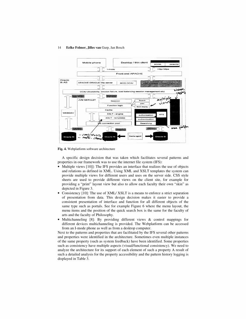
14 Eelke Folmer, Jilles van Gurp, Jan Bosch
Fig. 4. Webplatform software architecture
A specific design decision that was taken which facilitates several patterns and properties in our framework was to use the internet file system (IFS): • Multiple views [10]]: The IFS provides an interface that realizes the use of objects
and relations as defined in XML. Using XML and XSLT templates the system can provide multiple views for different users and uses on the server side. CSS style sheets are used to provide different views on the client site, for example for providing a “print” layout view but also to allow each faculty their own “skin” as depicted in Figure 3.
• Consistency [10]: The use of XML/ XSLT is a means to enforce a strict separation of presentation from data. This design decision makes it easier to provide a consistent presentation of interface and function for all different objects of the same type such as portals. See for example Figure 6 where the menu layout, the menu items and the position of the quick search box is the same for the faculty of arts and the faculty of Philosophy.
• Multichanneling [8]: By providing different views & control mappings for different devices multichanneling is provided. The Webplatform can be accessed from an I-mode phone as well as from a desktop computer.
Next to the patterns and properties that are facilitated by the IFS several other patterns and properties were identified in the architecture. Sometimes even multiple instances of the same property (such as system feedback) have been identified. Some properties such as consistency have multiple aspects (visual/functional consistency). We need to analyze the architecture for its support of each element of such a property A result of such a detailed analysis for the property accessibility and the pattern history logging is displayed in Table 3.

Software Architecture Analysis of Usability 15
Fig. 5. Provide multiple views/ & Visual/Functional Consistency.
Table 3.
� �
&������'(���������%����� (����������� ���������� ���������)���������������� �� ������
���������������������������������������)�����*�����+���������
��������������,����������)�������-.���������������������������������������������������������/������������������������
(�0���������������������)����������������)������������������� � ����������� ��� ������ 0������� ���� ���)�� �� � ������
�����������������������������*���������)���������.���
&��������'�(��������������� �
• 1����������� ��
• 2������������
�
2����� ��������� ��� ���)����� ��� ���� ���� ���)��� ������ ���
���)���� � ������ ���� ��� (2���� ��� ������ ��)����� ����� ���
����������3%��������������
• �����������4�����
�
(� �������� ���� 1����� 5� ������ ����6� ���� 7��� ��/���� ���
��������������������������������
(�8)������������������
5.3. Evaluate scenarios
The next step is to evaluate the architecture’s support for the usage scenarios in the usage profile. As an example, we analyze usage scenario #4 “content administrator makes object” from table 2. For this scenario it has been determined by which patterns and properties, that have been identified in the architecture it is affected. It is important to identify whether a scenario is affected by a pattern or property that has been implemented in the architecture because this is not always the case. The result of such an analysis is shown in a support matrix in Table 3 for two scenarios. A checkmark indicates that the scenario is affected by at least one or more patterns or properties. Some properties such as consistency have multiple aspects (visual/functional consistency). For a thorough evaluation we need to analyze each scenario for each element of such a property. The support matrix is used together with the relations in the framework to find out whether a usage profile is sufficiently supported by the architecture. The usage profile that we created shows that scenario #4 has high values for learnability (4) and reliability (3). Several patterns and

16 Eelke Folmer, Jilles van Gurp, Jan Bosch
properties positively contribute to the support of this scenario. For example, the property consistency and the pattern context sensitive help increases learnability as can be analyzed from Figure 1. By analyzing for each pattern and property, the effect on usability, the support for this scenario is determined. Due to the lack of formalized knowledge at the architecture level, this step is very much guided by tacit knowledge (i.e. the undocumented knowledge of experienced software architects and usability engineers). For usage scenario #4, we have concluded that the architecture provides weak support. Learnability is very important for this scenario and patterns such as a wizard or workflow modeling or different user modes to support novice users could increase the learnability of this scenario.
Table 4. Architecture support matrix
Usability patterns Usability properties Scenario number
System Feedback
Actions for m
ultiple obj.
Cancel
Data validation
History Logging
Scripting
Multiple view
s
Multi C
hanneling
Undo
User M
odes
User Profiles
Wizard
Workflow
model
Em
ulation
Context sensitive help
Provide feedback
Error m
anagement
Consistency
Adaptability
Guidance
Explicit user control
Natural m
apping
Accessibility
�
Minim
ize cognitive load
1 � � � � � � � � � � � � � � � � � � � � � � � � 4 � � � � � � � � � � � � � � � � � � � � � � � �
5.4. Interpret the results
The result of the assessment of the Webplatform is that three scenarios are accepted, six are weakly accepted and that two scenarios are weakly rejected. The main cause for this is that we could not identify sufficient support for learnability for content administrators as was required by the usage profile. There is room for improvement; usability could be improved if provisions were made to facilitate patterns and properties that have not been considered. The usability requirement of consistency was one of the driving forces of design and our analysis shows that it has positive influence on the usability of the system. Apart from some general usability guidelines [17] stated in the functional requirements no clearly defined and verifiable usability requirements have been specified. Our conclusion concerning the assessment of the Webplatform is that the architecture provides sufficient support for the usage profile that we created. This does not necessarily guarantee that the final system will be usable since many other factors play a role in ensuring a system’s usability. Our analysis shows however that these usability issues may be repaired without major changes to the software architecture thus preventing high costs incurring adaptive maintenance activities once the system has been implemented.

Software Architecture Analysis of Usability 17
5.5. Validation
Whether the usage profile we created is fully representative for the required usability is open to dispute. However, the results from the user test that has recently been completed by the ECCOO is consistent with our findings. 65 test users (students, employees and graduate students) have tested 13 different portals. In the usability tests, the users had to perform specific tasks while being observed. The specific tasks that had to be performed are mostly related to the tasks navigation and quick search in our usage profile. After performing the tasks, users were interviewed about the relevance of the tasks they had to perform and the usability issues that were discovered. The main conclusions of the tests are: • Most of the usability issues that were detected were related to navigation, structure
and content. For example, users have difficulties finding particular information. Lack of hierarchy and structure is the main cause for this problem Although the architecture supports visual and functional consistency, organizations themselves are responsible for structuring their information.
• Searching does not generate accurate search results. This may be fixed by technical modifications. E.g. tuning the search function to generate more accurate search results. (This is also caused by that a lot of meta-information on the content in the system has not been provided yet).
The results of this usability tests fit the results of our analysis: the software architecture supports the right level of usability. Some usability issues came up that where not predicted during our architectural assessment. However, these do not appear to be caused by problems in the software architecture. Future usability tests will focus on analyzing the usability of the scenarios that involve content administrators. Preliminary results from these tests show that the system has a weak support for learnability as predicted from the architectural analysis.
7. Conclusions
In this paper, we have presented SALUTA, a scenario based assessment technique that assists software architects in designing a software architecture that supports usability. SALUTA consists of four major steps: First, the required usability of the system is expressed by means of a usage profile. The usage profile consists of a representative set of usage scenarios that express the required usability of the system. The following sub-steps are taken for creating a usage profile: identify the users, identify the tasks, identify the contexts of use, determine attribute values, scenario selection & weighing. In the second step, the information about the software architecture is collected using a framework that has been developed in earlier work. This framework consists of an integrated set of design solutions such as usability patterns and usability properties that have a positive effect on usability but are difficult to retrofit into applications because they have architectural impact. This framework is used to analyze the architecture for its support of usability. The next step is to evaluate the architecture’s support of usage profile using the information extracted in the previous step. To do so, we perform support analysis for each of the

18 Eelke Folmer, Jilles van Gurp, Jan Bosch
scenarios in the set. The final step is then to interpret these results and to draw conclusions about the software architecture. The result of the assessment for example, which scenarios are poorly supported or which usability properties or patterns have not been considered, may guide the architect in applying particular transformations to improve the architecture’s support of usability. We have elaborated the various steps in this paper, discussed the issues and techniques for each of the steps, and illustrated these by discussing some examples from a case study. The main contributions of this paper are: • SALUTA is the first and currently the only technique that enables software
architects to assess the level of usability supported by their architectures. • Because usability requirements tend to change over time and may be discovered
during deployment, SALUTA may assist a software architect to come up with a more usable first version of a software architecture that might allow for more “usability tuning” on the detailed design level. This prevents some of the high costs incurring adaptive maintenance activities once the system has been implemented.
Future work shall focus on finalizing the case studies, refining the usability framework and validating our claims we make. Preliminary experiences with these three case studies shows the results from the assessment seem reasonable and do not conflict with the user tests. In the future, we will not only focus on assessing with SALUTA but also on using the framework for iteratively designing software architectures with SALUTA.
Acknowledgments
This work is sponsored by the STATUS1 project under contract no IST-2001-32298. We would like to thank the partners in the STATUS project and ECCOO for their input and their cooperation.
References
[1] R. S. Pressman, Software Engineering: A Practitioner's Approach, McGraw-Hill, NY, 1992.
[2] T. K. Landauer, The Trouble with Computers: Usefulness, Usability and Productivity., MIT Press., Cambridge, 1995.
[3] J. Bosch, Design and use of Software Architectures: Adopting and evolving a product line approach, Pearson Education (Addison-Wesley and ACM Press), Harlow, 2000.
[4] IEEE, IEEE Architecture Working Group. Recommended practice for architectural description. Draft IEEE Standard P1471/D4.1, IEEE, 1998.
1 STATUS is an ESPRIT project (IST-2001-32298) financed by the European Commission in
its Information Society Technologies Program. The partners are Information Highway Group (IHG), Universidad Politecnica de Madrid (UPM), University of Groningen (RUG), Imperial College of Science, Technology and Medicine (ICSTM), LOGICDIS S.A.

Software Architecture Analysis of Usability 19
[5] N. Lassing, P. O. Bengtsson, H. van Vliet, and J. Bosch, Experiences with ALMA: Architecture-Level Modifiability Analysis, Journal of systems and software, Elsevier, 2002, pp. 47-57.
[6] E. Folmer and J. Bosch, Architecting for usability; a survey, Journal of systems and software, Elsevier, 2002, pp. 61-78.
[7] F. Buschmann, R. Meunier, H. Rohnert, P. Sommerlad, and M. Stal, Pattern-Oriented Software Architecture: A System of Patterns, John Wiley and Son Ltd, New York, 1996.
[8] E. Gamma, R. Helm, R. Johnson, and J. Vlissides, Design patterns elements of reusable object-orientated software., Addison -Wesley, 1995.
[9] L. Bass, J. Kates, and B. E. John, Achieving Usability through software architecture, 1-3-2001.
[10] E. Folmer, J. v. Gurp, and J. Bosch, Investigating the Relationship between Usability and Software Architecture , Software process improvement and practice, Wiley, 2003, pp. 0-0.
[11] J. Tidwell, Interaction Design Patterns, Conference on Pattern Languages of Programming 1998, 1998.
[12] Brighton, The Brighton Usability Pattern Collection. http://www.cmis.brighton.ac.uk/research/patterns/home.html
[13] L. Bass, P. Clements, and R. Kazman, Software Architecture in Practice, Addison Wesley Longman, Reading MA, 1998.
[14] R. Kazman, M. Klein, M. Barbacci, T. Longstaff, H. Lipson, and J. Carriere, The Architecture Tradeoff Analysis Method, Proceedings of ICECCS'98, 8-1-1998.
[15] W. Li and S. Henry, OO Metrics that Predict Maintainability, Journal of systems and software, Elsevier, 1993, pp. 111-122.
[16] J. Nielsen, Heuristic Evaluation., in Usability Inspection Methods., Nielsen, J. and Mack, R. L., John Wiley and Sons, New York, NY., 1994.
[17] J. Nielsen, Usability Engineering, Academic Press, Inc, Boston, MA., 1993. [18] C. Wharton, J. Rieman, C. H. Lewis, and P. G. Polson, The Cognitive Walkthrough: A
practitioner's guide., in Usability Inspection Methods, Nielsen, Jacob and Mack, R. L., John Wiley and Sons, New York, NY., 1994.
[19] R. Kazman, G. Abowd, and M. Webb, SAAM: A Method for Analyzing the Properties of Software Architectures, Proceedings of the 16th International Conference on Software Engineering, 1994.
[20] S. Lauesen and H. Younessi, Six styles for usability requirements, Proceedings of REFSQ'98, 1998.
[21] J. Preece, Y. Rogers, H. Sharp, D. Benyon, S. Holland, and T. Carey, Human-Computer Interaction, Addison Wesley, 1994.
[22] D. Hix and H. R. Hartson, Developing User Interfaces: Ensuring Usability Through Product and Process., John Wiley and Sons, 1993.
[23] ISO, ISO 9241-11 Ergonomic requirements for office work with visual display terminals (VDTs) -- Part 11: Guidance on usability., 1994.
[24] B. Shneiderman, Designing the User Interface: Strategies for Effective Human-Computer Interaction, Addison-Wesley, Reading, MA, 1998.
[25] J. v. Gurp and J. Bosch, Design Erosion: Problems and Causes, Journal of systems and software, Elsevier, 3-1-2002, pp. 105-119.
[26] P. B. Kruchten, The 4+1 View Model of Architecture, IEEE Software, 1995. [27] C. Argyris, R. Putnam, and D. Smith, Action Science: Concepts, methods and skills for
research and intervention, Jossey-Bass, San Francisco, 1985.
Recommended