Ž .Thin Solid Films 313]314 1998 53]57
Spectrophotopolarimeter based on multiple reflectionsin a coated dielectric slab
R.M.A. Azzama,U , A.M. El-Sabab, M.A.G. Abushagur b
aDepartment of Electrical Engineering, Uni¨ersity of New Orleans, New Orleans, LA 70148, USAbDepartment of Electrical and Computer Engineering, Uni¨ersity of Alabama in Hunts¨ille, Hunts¨ille, AL 35899, USA
Abstract
A division-of-amplitude photopolarimeter is described that uses multiple reflections inside a coated dielectric slab atoblique incidence. The first four parallel reflected beams pass through suitably oriented, but fixed, linear analyzers and areintercepted by linear photodetector arrays for spectroscopic polarimetry and ellipsometry. A particular design is presentedthat uses a parallel-plane fused-silica slab which is coated with an opaque reflecting layer of Ag or Al on the back side andwith a transparent ZnS thin film on the front side. Sufficient power is available in the high orders and the instrument matrix isnon-singular, so that all four Stokes parameters of the input light can be measured simultaneously, over the visible andnear-visible spectral range. Q 1998 Elsevier Science S.A.
Keywords: Ellipsometry; Polarimetry; Optical coatings
1. Introduction
Fast and complete measurement of the state ofpolarization of light is possible using simple andrugged multi-detector photopolarimeters that operate
w xwith no moving parts or modulators 1,2 . Such instru-w xments use the division of wavefront 3 or division of
w xamplitude 4]8 to obtain simultaneously at least fourlinearly independent projections of the unknown
ŽStokes vector of light such as that reflected by a.surface in ellipsometry .
In a division-of-amplitude photopolarimeterŽ .DOAP , the light beam whose Stokes vector is to bemeasured is split into four or more beams using
U Corresponding author. On sabbatical leave at the AmericanUniversity in Cairo, School of Sciences and Engineering, P.O. Box2511, Cairo 11511, Egypt. Fax: 202 355-7565; e-mail:[email protected]
appropriate optics and the component beams are in-tercepted by photodetectors to generate an outputsignal vector that is linearly related to the unknowninput Stokes vector. The four-detector photopolar-
w ximeter 9]11 , that uses partially reflective silicondetectors and no other optical elements, may be con-sidered as an irreducible DOAP. Because of theirmultiple-beam-splitting, polarization-altering and dis-persive properties, diffraction gratings are suited forboth single-wavelength and spectroscopic DOAPw x12]16 . The principal limitation of most DOAPs isthe first-order dependence of the instrument matrixon incidence-angle errors which restricts the field ofview and necessitates precise alignment.
w xIn a previous letter 17 , a parallel-slab DOAP withseveral interesting features was described. In thispaper we report on a modified design with signifi-cantly improved performance over the visible andnear-visible spectrum.
0040-6090r98r$19.00 Q 1998 Elsevier Science S.A. All rights reservedŽ .P I I S 0 0 4 0 - 6 0 9 0 9 7 0 0 7 6 8 - 2
( )R.M.A. Azzam et al. r Thin Solid Films 313]314 1998 53]5754
2. Coated parallel-slab photopolarimeter
Fig. 1 shows the basic arrangement of this DOAP.The key element is a parallel-plane dielectric-slab
Ž .beam splitter of refractive index n l and thickness1d. The bottom surface of the slab is coated with anopaque, highly reflective metal layer of complex re-
Ž .fractive index N l sn y jk , where l is the wave-2 2 2length of light. The light beam, whose polarization is
Žto be measured, is incident from air or vacuum n s0. Ž1 on the top surface of the slab which may be coated
.by a transparent thin film at an angle of incidence f.Multiple internal reflections within the slab produce aset of parallel, equi-spaced, reflected beams, num-bered 0, 1, 2, 3,..., that are intercepted by photodetec-tors D , D , D , D ,.... to generate output electrical0 1 2 3signals i , i , i , i ,..., respectively. Linear polarization0 1 2 3analyzers P , P , P , P ,... are placed in the respec-0 1 2 3tive reflected beams between the slab and the detec-tors. The transmission axes of these analyzers areinclined with respect to the plane of incidence byazimuth angles A , A , A , A ,.... The output signal0 1 2 3of the mth detector is a linear combination of the
Ž .four Stokes parameters S js0, 1, 2, 3 of thejincident light, i.e.
3Ž .i s a S , ms0, 1, 2, . . . 1Ým m j j
js0
w xThe mth projection vector a s a a a am m0 m1 m2 m3is the first row of the Mueller matrix of the mth lightpath through the slab and the mth analyzer to thedetector. When four signals are detected, the output
w xtcurrent vector Is i i i i is linearly related to0 1 2 3w xt Žthe input Stokes vector Ss S S S S where t0 1 2 3
.denotes the transpose by
Ž .IsAS 2
A is a 4=4 instrument matrix whose rows are a .mAs with other DOAPs, this matrix is measured sepa-
Fig. 1. Parallel-slab division-of-amplitude photopolarimeter.
w xrately by calibration 18 . The unknown Stokes vectorS is obtained subsequently by
y1 Ž .SsA I 3
The analyzers are oriented at the equi-spaced azi-muths A s908, A s458, A s08 and A sy458,0 1 2 3which simplify the instrument matrix and provide highoverall polarimetric sensitivity. The analyzer orienta-
Ž .tions in the first and third beams A and A are0 2w xswitched relative to those suggested in 17 , which
leads to a significant improvement in performance.The determinant of the instrument matrix becomes:
3Ž . Ž .detAs 1r8 k rŁ q q
qs0
w Ž .x w Ž .x w Ž .x= 1qcos 2c 1ycos 2c sin 2c0 2 1
w Ž .x w Ž .x Ž .= sin 2c sin D yD 43 1 3
Ž .The derivation leading to Eq. 4 is similar to thatfor the DOAP based on planar grating diffractionw x Ž . Ž14 . In Eq. 4 r is the net power reflectance orq
.throughput of the slab for the qth order, k is theqresponsivity of the qth detector, and c , D are theq qellipsometric parameters that characterize the inter-action of the incident light beam with the slab thatproduces the qth reflected order.
3. ZnS–SiO –Ag coated-slab single-wavelength2photopolarimeter
Ž .We propose a design that uses a fused-silica SiO2slab which is coated with an optically thick Ag layeron the back side and with a 70-nm transparent ZnS
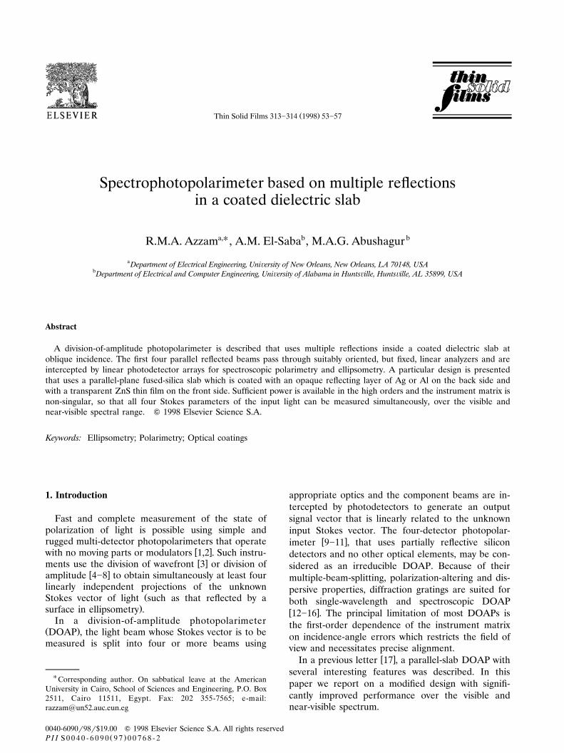
Fig. 2. Fractional powers as functions of the angle of incidence forthe first four beams reflected by a ZnSrSiO rAg parallel slab at2633-nm wavelength. The ZnS coating thickness is 70 nm.
( )R.M.A. Azzam et al. r Thin Solid Films 313]314 1998 53]57 55
thin film on the front side. The ZnS coating thickness,which differs from that suggested by El-Saba et al.w x17 , is selected for maximum power in the third andfourth beams at the He]Ne-laser wavelength of 633nm. The optical properties of ZnS, SiO , and Ag are2
w xgiven by Palik 19 .The calculated fractional powers in the first four
reflected beams for incident unpolarized light of 633-nm wavelength are shown in Fig. 2 as functions of theangle of incidence f. Acceptable partition of poweramong the first four orders is achieved in the mid-
Ž .range of incidence angles 40]508 which is desirablefor reduced angular sensitivity. At fs408, the frac-tional powers are 34, 43, 12 and 4%, in the 0th, 1st,2nd and 3rd orders, respectively. The lowest power inthe highest-order beam is sufficient for completepolarization analysis. A more even distribution ofpower can only be achieved with a more complicatedcoating design.
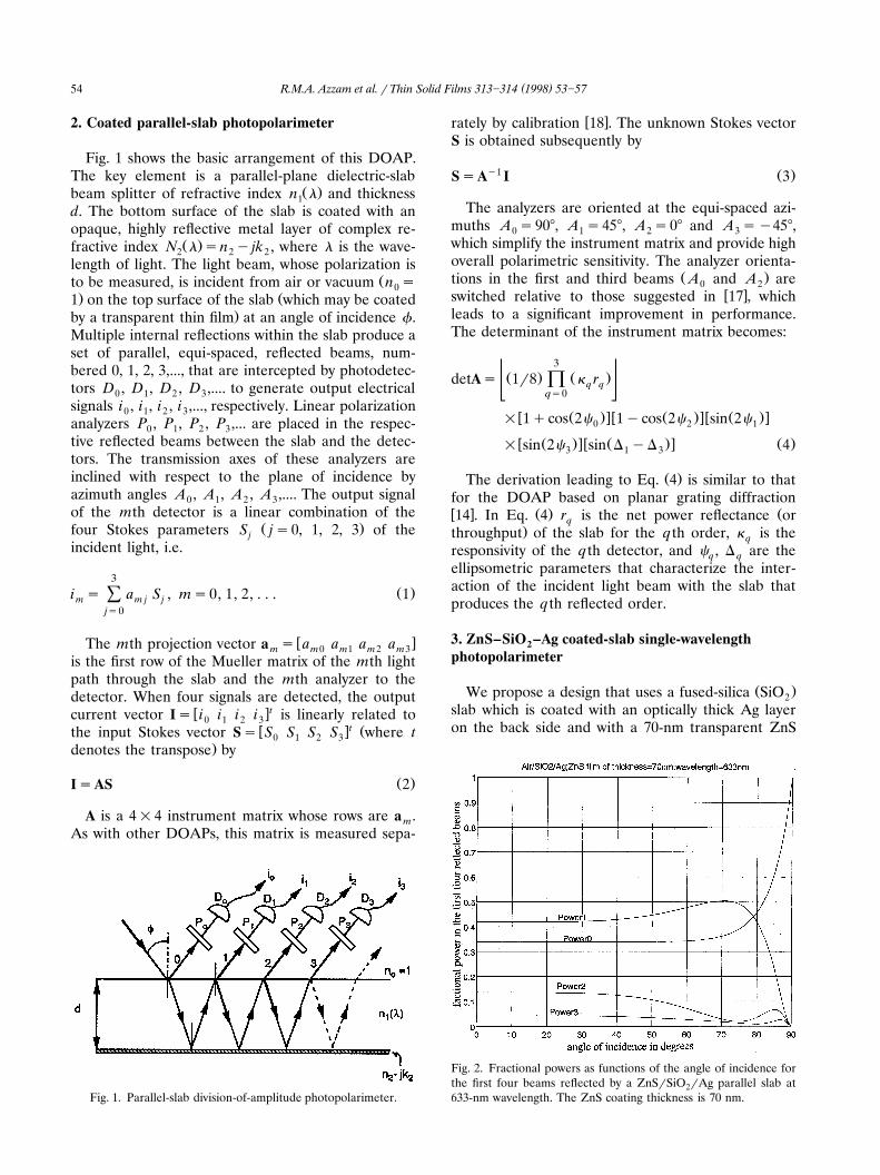
Fig. 3 shows the normalized determinant of theŽ .instrument matrix, obtained by dividing Eq. 4 by the
first bracketed term on the right-hand side, as afunction of f for the DOAP using the ZnSrSiO rAg2system at ls633 nm. The determinant is non-zero,hence the instrument matrix is non-singular, overmost of the range of f, and has a maximum nearfs508. The flat singularity near 738 is associatedwith the near total suppression of the p polarization
Ž .in the fourth beam and the last two terms in Eq. 4being both nearly 0 at that angle. The second peak at828 is not useful because of excessive angular sensitiv-ity near grazing incidence. Operation at 408, wherethe determinant is still a large fraction of its peak
Fig. 3. Normalized determinant of the instrument matrix as afunction of angle of incidence for a DOAP using a ZnSrSiO rAg2parallel slab at 633-nm wavelength. The ZnS coating thickness is 70nm.
value, is recommended based on partition-of-powerand field-of-view considerations.
4. Spectroscopic photopolarimetry
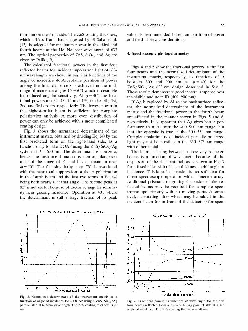
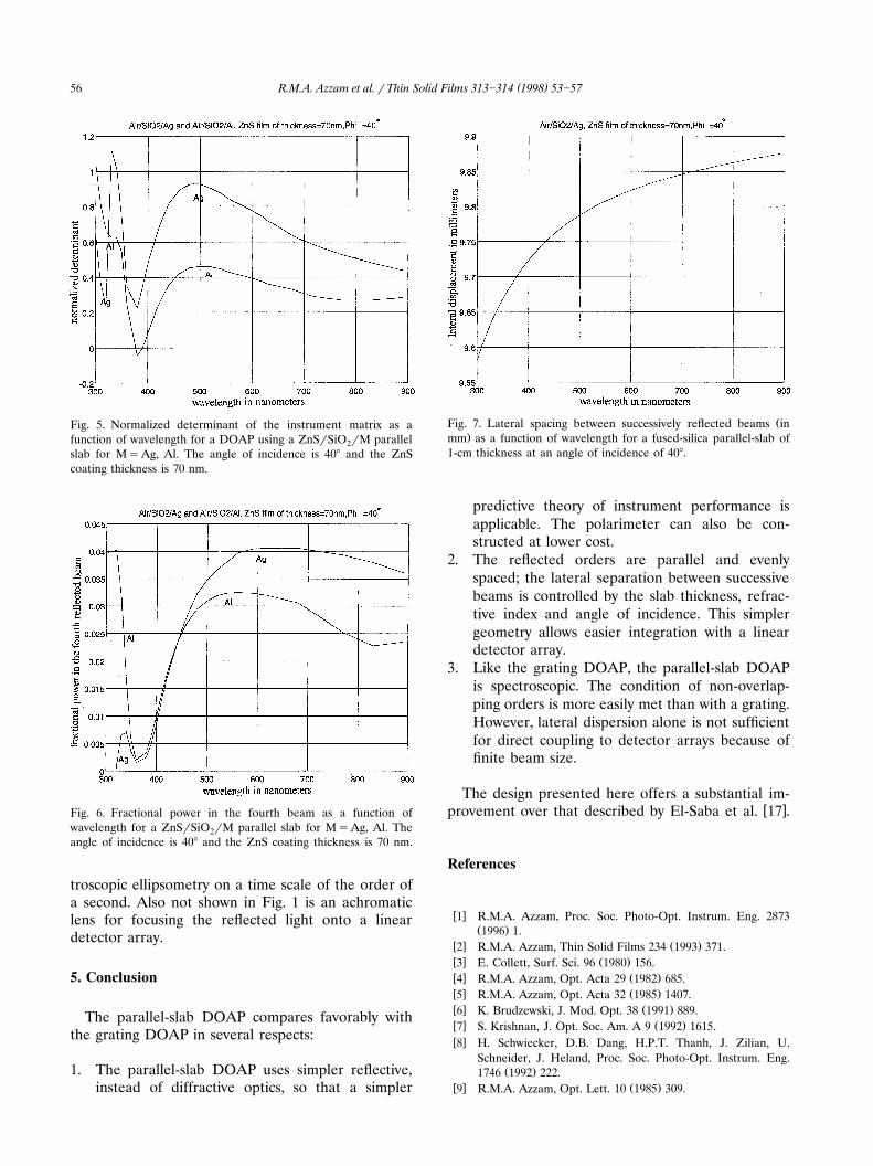
Figs. 4 and 5 show the fractional powers in the firstfour beams and the normalized determinant of theinstrument matrix, respectively, as functions of lbetween 300 and 900 nm at f s 408 for theZnSrSiO rAg 633-nm design described in Sec. 3.2These results demonstrate good spectral response over
Ž .the visible and near IR 400]900 nm .If Ag is replaced by Al as the back-surface reflec-
tor, the normalized determinant of the instrumentmatrix and the fractional power in the fourth beamare affected in the manner shown in Figs. 5 and 6,respectively. It is apparent that Ag gives better per-formance than Al over the 400]900 nm range, butthat the opposite is true in the 300]350 nm range.Complete polarimetry of incident partially polarizedlight may not be possible in the 350]375 nm rangewith either metal.
The lateral spacing between successively reflectedbeams is a function of wavelength because of thedispersion of the slab material, as is shown in Fig. 7for a fused-silica slab of 1-cm thickness at 408 angle ofincidence. This lateral dispersion is not sufficient fordirect spectroscopic operation with a detector array.Additional prismatic or grating dispersion of the re-flected beams may be required for complete spec-trophotopolarimetry with no moving parts. Alterna-tively, a rotating filter wheel may be added in the
Ž .incident beam or in front of the detector for spec-
Fig. 4. Fractional powers as functions of wavelength for the firstfour beams reflected from a ZnSrSiO rAg parallel slab at a 4082angle of incidence. The ZnS coating thickness is 70 nm.
( )R.M.A. Azzam et al. r Thin Solid Films 313]314 1998 53]5756
Fig. 5. Normalized determinant of the instrument matrix as afunction of wavelength for a DOAP using a ZnSrSiO rM parallel2slab for MsAg, Al. The angle of incidence is 408 and the ZnScoating thickness is 70 nm.
Fig. 6. Fractional power in the fourth beam as a function ofwavelength for a ZnSrSiO rM parallel slab for MsAg, Al. The2angle of incidence is 408 and the ZnS coating thickness is 70 nm.
troscopic ellipsometry on a time scale of the order ofa second. Also not shown in Fig. 1 is an achromaticlens for focusing the reflected light onto a lineardetector array.
5. Conclusion
The parallel-slab DOAP compares favorably withthe grating DOAP in several respects:
1. The parallel-slab DOAP uses simpler reflective,instead of diffractive optics, so that a simpler
ŽFig. 7. Lateral spacing between successively reflected beams in.mm as a function of wavelength for a fused-silica parallel-slab of
1-cm thickness at an angle of incidence of 408.
predictive theory of instrument performance isapplicable. The polarimeter can also be con-structed at lower cost.
2. The reflected orders are parallel and evenlyspaced; the lateral separation between successivebeams is controlled by the slab thickness, refrac-tive index and angle of incidence. This simplergeometry allows easier integration with a lineardetector array.
3. Like the grating DOAP, the parallel-slab DOAPis spectroscopic. The condition of non-overlap-ping orders is more easily met than with a grating.However, lateral dispersion alone is not sufficientfor direct coupling to detector arrays because offinite beam size.
The design presented here offers a substantial im-w xprovement over that described by El-Saba et al. 17 .
References
w x1 R.M.A. Azzam, Proc. Soc. Photo-Opt. Instrum. Eng. 2873Ž .1996 1.
w x Ž .2 R.M.A. Azzam, Thin Solid Films 234 1993 371.w x Ž .3 E. Collett, Surf. Sci. 96 1980 156.w x Ž .4 R.M.A. Azzam, Opt. Acta 29 1982 685.w x Ž .5 R.M.A. Azzam, Opt. Acta 32 1985 1407.w x Ž .6 K. Brudzewski, J. Mod. Opt. 38 1991 889.w x Ž .7 S. Krishnan, J. Opt. Soc. Am. A 9 1992 1615.w x8 H. Schwiecker, D.B. Dang, H.P.T. Thanh, J. Zilian, U.
Schneider, J. Heland, Proc. Soc. Photo-Opt. Instrum. Eng.Ž .1746 1992 222.
w x Ž .9 R.M.A. Azzam, Opt. Lett. 10 1985 309.

( )R.M.A. Azzam et al. r Thin Solid Films 313]314 1998 53]57 57
w x10 R.M.A. Azzam, I.M. Elminyawi, A.M. El-Saba, J. Opt. Soc.Ž .Am. A 5 1988 681.
w x11 R.M.A. Azzam, E. Masetti, I.M. Elminyawi, F.G. Grosz, Rev.Ž .Sci. Instrum. 59 1988 84.
w x Ž .12 R.M.A. Azzam, Appl. Opt. 31 1992 3574.w x Ž .13 T. Todorov, L. Nikolova, Opt. Lett. 17 1992 358.w x Ž .14 R.M.A. Azzam, K.A. Giardina, J. Opt. Soc. Am A 10 1993
1190.
w x Ž .15 Y. Cui, R.M.A. Azzam, Rev. Sci. Instrum. 66 1995 5552.w x Ž .16 Y. Cui, R.M.A. Azzam, Opt. Lett. 21 1996 89.w x17 A.M. El-Saba, R.M.A. Azzam, M.A.G. Abushagur, Opt. Lett.
Ž .21 1996 1709.w x Ž .18 R.M.A. Azzam, A.G. Lopez, J. Opt. Soc. Am. A 6 1989
1513.w x Ž .19 E.D. Palik Ed. , Handbook of Optical Constants of Solids,
Academic, New York, 1985.
Recommended


![AUTOREFERAT€¦ · [4] R. Lech, W. Marynowski, A. Kusiek, "An Analysis of Elliptical-Rectangular Multipatch Structure on Dielectric-Coated Confocal and Nonconfocal Elliptic Cylinders",](https://img.pdfslide.net/doc/110x75/606655be8257ee71175410ad/autoreferat-4-r-lech-w-marynowski-a-kusiek-an-analysis-of-elliptical-rectangular.jpg)