H-41
(A) Photoelectric Sensors
(B) FiberOpticSensors
(C) Door/AreaSensors
(D) ProximitySensors
(E) PressureSensors
(F) RotaryEncoders
(G) Connectors/Sockets
(H)TemperatureControllers
(I)SSRs / PowerControllers
(J) Counters
(K) Timers
(L) PanelMeters
(M)Tacho /Speed / PulseMeters
(N)DisplayUnits
(O)SensorControllers
(P)SwitchingMode PowerSupplies
(Q)Stepper Motors & Drivers & Controllers
(R)Graphic/LogicPanels
(S)FieldNetworkDevices
(T) Software
Economical Dual Display Type, PID ControlTCN Series
FeaturesEconomical Dual Display Type, PID Control
Realizesidealtemp.controllingwithnewlydevelopedPIDcontrolalgorithmand100mshighspeedsamplingBuilt-in relay output or SSR drive output selectable : Enables to phase control and cycle control with SSR drive output (SSRP function)DramaticallyincreasedvisibilityusingwidedisplaypartEnhancedconvenienceofwiringandmaintenancebyconnectorplugtype(TCN4S- -P)
Mountingspacesavingwithcompactdesign:Approx.38%reducedsizecomparedwithexistingmodel(depth-based)
Ordering Information
SpecificationsSeries TCN4S TCN4M TCN4H TCN4L Powersupply
ACpower 100-240VAC50/60HzAC/DCpower 24VAC50/60Hz,24-48VDC
Allowablevoltagerange 90to110%ofratedvoltagePowerconsumption
ACpower Max.5VA(100-240VAC50/60Hz)AC/DCpower Max.5VA(24VAC50/60Hz),Max.3W(24-48VDC)
Displaymethod 7Segment(PV:red,SV:green),Otherdisplay(green,red)LEDCharactersize
PV(W×H) 7.0×15.0mm 9.5×20.0mm 7.0×14.6mm 11.0×22.0mmSV(W×H) 5.0×9.5mm 7.5×15.0mm 6.0×12.0mm 7.0×14.0mm
InputtypeRTD DPt100Ω,Cu50Ω(allowablelineresistancemax.5Ωperawire)Thermocouple K(CA),J(IC),L(IC),T(CC),R(PR),S(PR)
Displayaccuracy※1
RTD Atroomtemperature(23 ±5):(PV±0.5%or±1, select the higherone)±1digitOutofroomtemperaturerange:(PV±0.5%or±2, select the higherone)±1digitForTCN4S- -P,add±1byaccuracystandard.Thermocouple
Controloutput
Relay 250VAC3A1aSSR 12VDC±2V20mAMax.
Alarmoutput AL1,AL2Relayoutput:250VAC1A1aControlmethod ON/OFFcontrol,P,PI,PD,PIDcontrolHysteresis 1to100/ (0.1to50.0/)variable※1: Atroomtemperature(23±5)
ThermocoupleR(PR),S(PR),below200: (PV±0.5%or±3, select the higherone)±1digitThermocoupleR(PR),S(PR),over200:(PV±0.5%or±2, select the higherone)±1digitThermocoupleL(IC),RTDCu50Ω:(PV±0.5%or±2, select the higherone)±1digit
OutofroomtemperaturerangeThermocoupleR(PR),S(PR),below200: (PV±1.0%or±6, select the higherone)±1digitThermocoupleR(PR),S(PR),over200:(PV±0.5%or±5, select the higherone±1digitThermocoupleL(IC),RTDCu50Ω:(PV±0.5%or±3, select the higherone)±1digitForTCN4S- -P,add±1byaccuracystandard.
Settingtype
Item
Digit
Size
Auxiliaryoutput
Powersupply
Controloutput
Wiringmethod
No-mark BoltwiringmethodP Connectorplugconnectionmethod※1
R Relaycontactoutput+SSRdriveoutput※2
2 24VAC50/60Hz,24-48VDC4 100-240VAC50/60Hz
2 Alarm1+Alarm2output
S DINW48×H48mmM DINW72×H72mmH DINW48×H96mmL DINW96×H96mm
4 9999(4digit)
CN Dualdisplaytype,setbytouchswitch
T Temperaturecontroller
CNT S 2 P4 R4
Connector plug type(TCN4S- -P)
Line-up
1: OnlyforTCN4Smodel. 2:IncaseoftheACvoltagemodel,SSRdriveoutputmethod(standardON/OFFcontrol,cyclecontrol,phasecontrol)isavailabletoselect.
H-42
TCN Series
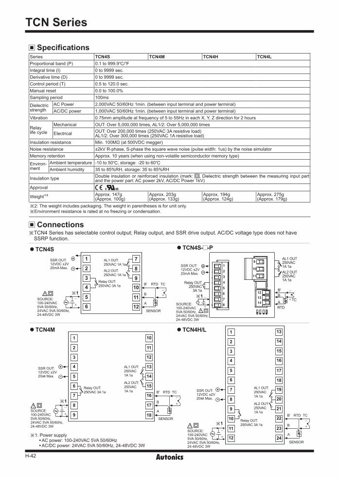
Specifications
Connections
TCN4S
TCN4M
※ TCN4Serieshasselectablecontroloutput;Relayoutput,andSSRdriveoutput.AC/DCvoltagetypedoesnothaveSSRPfunction.
※2: Theweightincludespackaging.Theweightinparenthesesisforunitonly.※Environmentresistanceisratedatnofreezingorcondensation.
※1:PowersupplyACpower:100-240VAC5VA50/60HzAC/DCpower:24VAC5VA50/60Hz,24-48VDC3W
Series TCN4S TCN4M TCN4H TCN4L Proportionalband(P) 0.1to999.9/Integraltime(I) 0to9999sec.Derivativetime(D) 0to9999sec.Controlperiod(T) 0.5to120.0sec.Manualreset 0.0to100.0%Samplingperiod 100ms
Dielectricstrength
ACPower 2,000VAC50/60Hz1min.(betweeninputterminalandpowerterminal)AC/DCpower 1,000VAC50/60Hz1min.(betweeninputterminalandpowerterminal)
Vibration 0.75mmamplitudeatfrequencyof5to55HzineachX,Y,Zdirectionfor2hours
Relaylifecycle
Mechanical OUT:Over5,000,000times,AL1/2:Over5,000,000times
Electrical OUT:Over200,000times(250VAC3Aresistiveload)AL1/2:Over300,000times(250VAC1Aresistiveload)
Insulationresistance Min.100MΩ(at500VDCmegger)Noiseresistance ±2kVR-phase,S-phasethesquarewavenoise(pulsewidth:1us)bythenoisesimulatorMemoryretention Approx.10years(whenusingnon-volatilesemiconductormemorytype)
Environ-ment
Ambienttemperature -10to50,storage:-20to60Ambienthumidity 35to85%RH,storage:35to85%RH
Insulationtype Doubleinsulationorreinforcedinsulation(mark: ,Dielectricstrengthbetweenthemeasuringinputpartandthepowerpart:ACpower2kV,AC/DCPower1kV)
Approval
Weight※2 Approx.147g(Approx.100g)
Approx.203g(Approx.133g)
Approx.194g(Approx.124g)
Approx.275g(Approx.179g)
13
19
14
20
15
21
16
22
17
23
18
24
SSROUT:12VDC±2V20Max.
※1SOURCE:100-240VAC5VA50/60,24VAC5VA50/60,24-48VDC3W
B' RTD TC
SENSOR
AL1OUT:250VAC1A1a
AL2OUT:250VAC1A1a
RelayOUT:250VAC3A1a B
A
1
7
2
8
3
9
4
10
5
11
6
12
1 7
2 8
3 94 10
5 11
6 12
SSROUT:12VDC±2V20mAMax. SSROUT:
12VDC±2V20mAMax.
※1 ※1SOURCE:100-240VAC5VA50/60,24VAC5VA50/60,24-48VDC3W
SOURCE:100-240VAC5VA50/60,24VAC5VA50/60,24-48VDC3W
B' RTD TC
SENSOR
AL1OUT:250VAC1A1a
AL2OUT:250VAC1A1a
RelayOUT:250VAC3A1a
B
A
TCN4H/L1
7
2
8
3
9
4
5
6
10
11
12
13
14
15
16
17
18
SSROUT:12VDC±2V20Max.
※1
SOURCE:100-240VAC5VA50/60,24VAC5VA50/60,24-48VDC3W
B' RTD TC
SENSOR
AL1OUT:250VAC1A1a
AL2OUT:250VAC1A1a
RelayOUT:250VAC3A1a
B
A
TCN4S- -P
AL1OUT250VAC1A1aAL2OUT250VAC1A1a
B'
RTD
B
A
RelayOUT250VAC3A1a
TC
H-43
Economical Dual Display Type, PID Control
(A) Photoelectric Sensors
(B) FiberOpticSensors
(C) Door/AreaSensors
(D) ProximitySensors
(E) PressureSensors
(F) RotaryEncoders
(G) Connectors/Sockets
(H)TemperatureControllers
(I)SSRs / PowerControllers
(J) Counters
(K) Timers
(L) PanelMeters
(M)Tacho /Speed / PulseMeters
(N)DisplayUnits
(O)SensorControllers
(P)SwitchingMode PowerSupplies
(Q)Stepper Motors & Drivers & Controllers
(R)Graphic/LogicPanels
(S)FieldNetworkDevices
(T) Software
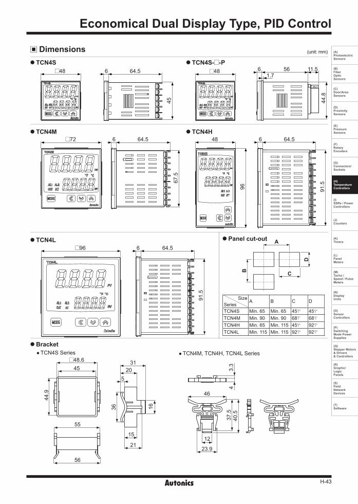
Dimensions (unit:mm)
TCN4S
TCN4M
TCN4L
Bracket
45
64.5648 TCN4S- -P
48
44.8
561.7
11.56
64.5
67.5
672 TCN4H
96
48
91.5
64.56
91.5
64.5696
TCN4SSeries TCN4M,TCN4H,TCN4LSeries
46
23.9
12
37.5
40.5
3.3
4 Panel cut-out
SizeSeries
A B C D
TCN4S Min.65 Min.65 45 0.60 45 0.6
0
TCN4M Min.90 Min.90 68 0.70 68 0.7
0
TCN4H Min.65 Min.115 45 0.60 92 0.8
0
TCN4L Min.115 Min.115 92 0.80 92 0.8
0
A
C
D
B
56
55
4548.6
44.9
3120
15
21
5
1636
H-44
TCN Series
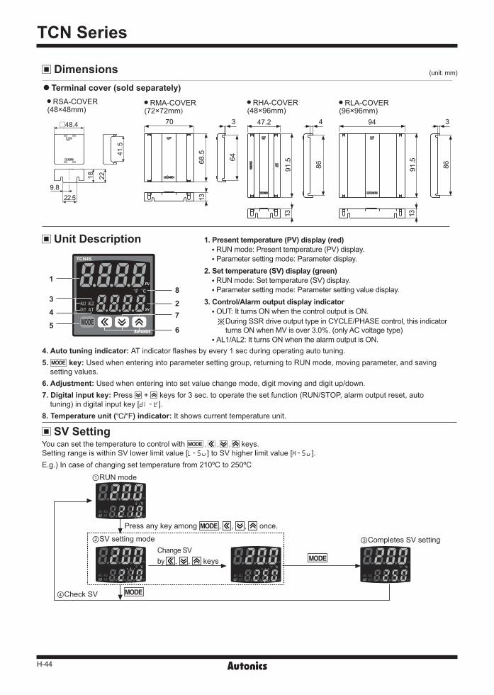
4. Auto tuning indicator: ATindicatorflashesbyevery1secduringoperatingautotuning.5. key:Usedwhenenteringintoparametersettinggroup,returningtoRUNmode,movingparameter,andsavingsettingvalues.
6. Adjustment: Usedwhenenteringintosetvaluechangemode,digitmovinganddigitup/down.7. Digital input key:Press + keysfor3sec.tooperatethesetfunction(RUN/STOP,alarmoutputreset,autotuning)indigitalinputkey[DI-K].
8. Temperature unit (/) indicator:Itshowscurrenttemperatureunit.
Unit Description
SV Setting
1
23
4
5 6
7
8
Youcansetthetemperaturetocontrolwith keys.SettingrangeiswithinSVlowerlimitvalue[L-SV]toSVhigherlimitvalue[H-SV].E.g.)Incaseofchangingsettemperaturefrom210ºCto250ºC
1. Present temperature (PV) display (red) RUNmode:Presenttemperature(PV)display. Parametersettingmode:Parameterdisplay.
2. Set temperature (SV) display (green) RUNmode:Settemperature(SV)display. Parametersettingmode:Parametersettingvaluedisplay.
3. Control/Alarm output display indicator OUT:ItturnsONwhenthecontroloutputisON. ※DuringSSRdriveoutputtypeinCYCLE/PHASEcontrol,thisindicator
turnsONwhenMVisover3.0%.(onlyACvoltagetype) AL1/AL2:ItturnsONwhenthealarmoutputisON.
Terminal cover (sold separately)
Dimensions (unit:mm)
RSA-COVER(48×48mm)
RMA-COVER(72×72mm)
RHA-COVER(48×96mm)
RLA-COVER(96×96mm)
70
68.5
3
64
13
91.5
86
4
13
47.2
91.5
86
3
13
9448.4
9.8
41.5
18 22
22.5
ChangeSVby , , keys
Pressanykeyamong , , , once.
①RUNmode
②SVsettingmode ③CompletesSVsetting
④CheckSV
H-45
Economical Dual Display Type, PID Control
(A) Photoelectric Sensors
(B) FiberOpticSensors
(C) Door/AreaSensors
(D) ProximitySensors
(E) PressureSensors
(F) RotaryEncoders
(G) Connectors/Sockets
(H)TemperatureControllers
(I)SSRs / PowerControllers
(J) Counters
(K) Timers
(L) PanelMeters
(M)Tacho /Speed / PulseMeters
(N)DisplayUnits
(O)SensorControllers
(P)SwitchingMode PowerSupplies
(Q)Stepper Motors & Drivers & Controllers
(R)Graphic/LogicPanels
(S)FieldNetworkDevices
(T) Software
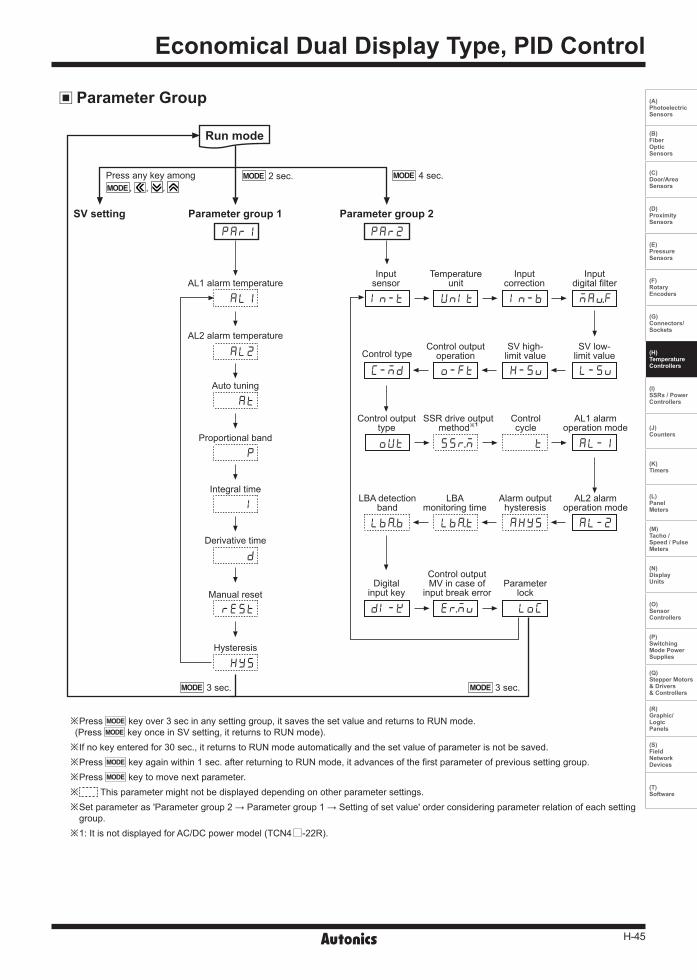
Parameter Group
※Press keyover3secinanysettinggroup,itsavesthesetvalueandreturnstoRUNmode.(Press keyonceinSVsetting,itreturnstoRUNmode).※Ifnokeyenteredfor30sec.,itreturnstoRUNmodeautomaticallyandthesetvalueofparameterisnotbesaved.※Press keyagainwithin1sec.afterreturningtoRUNmode,itadvancesofthefirstparameterofprevioussettinggroup.※Press keytomovenextparameter.※ Thisparametermightnotbedisplayeddependingonotherparametersettings.※ Setparameteras'Parametergroup2→Parametergroup1→Settingofsetvalue'orderconsideringparameterrelationofeachsettinggroup.
※1:ItisnotdisplayedforAC/DCpowermodel(TCN4 -22R).
Run mode
SV setting Parameter group 1 Parameter group 2
AL1alarmtemperature
AL2alarmtemperature
Inputsensor
Temperatureunit
Inputcorrection
Inputdigitalfilter
SVlow-limitvalue
SVhigh-limitvalue
ControloutputoperationControltype
Controloutputtype
SSRdriveoutputmethod※1
Controlcycle
AL1alarmoperationmode
AL2alarmoperationmode
Alarmoutputhysteresis
LBAmonitoringtime
LBAdetectionband
Digitalinputkey
ControloutputMVincaseof
inputbreakerrorParameter
lock
Autotuning
Proportionalband
Integraltime
Derivativetime
Manualreset
Hysteresis
Pressanykeyamong, , ,
PAR1
IN-Tㅑㅑ MAvF
PAR2
AL1 UNIT IN-Bㅑㅑ
L-SV H-SV O-FTC-MD
OUT SSrM T AL-1
AL-2AHYSLBaTLBaㅑㅑB
DI-K ErMV LOC
AL2
AT
P
I
D
REST
HYS
2sec.
3sec. 3sec.
4sec.

H-46
TCN Series
※1:S :Pressanykeyamong , , .※2:Aftercheckingorchangingsettingvalueineachparameter,press keytosave
andmovetonextparametersetting.※3:Itisdisplayedwhencontroltypeparameter[C-MD]ofparametergroup2isset PID.※Press keyfor3sec.toreturnRUNmodeatanyparameter.※ Thisparametermightnotbedisplayeddependingonotherparametersettings.
Settingrange:Deviationalarm(-F.StoF.S),Absolutevaluealarm(temperaturerange)※ Incasealarmoperationmode[AL-2]ofParametergroup2isAM)_/SBa /BA ,noparametersisdisplayed.
Settingrange:0.1to999.9/
Settingrange:0to9999sec.※IntegraloperationisOFFwhensetvalueis"0".
Settingrange:0to9999sec.※DerivativeoperationisOFFwhensetvalueis"0".
Settingrange:0.0to100.0%※ItisdisplayedinP,PDcontrol.
Settingrange KCaH, JIcH,LIcH,TCcH,RPR,SRP,DPtH,CUsH:1to100/ KCaL, JIcL,LIcL,TCcL,DPtL,CUsL:0.1to50.0/※Itisdisplayedwhencontroltype[C-MD]ofparametergroup2issetONOF.
※FrontATindicatorflashesduringautotuningoperation.
Settingrange KCaH, JIcH,LIcH,TCcH,RPR,SRP,DPtH,CUsH:-999to999/ KCaL, JIcL,LIcL,TCcL,DPtL,CUsL:-199.9to999.9/
Settingrange:0.1to120.0sec.※ Setinputdigitalfiltertimeforaverageinputvalueaffectedcontrol,anddisplayvalue.
※ Ifchangingtemperatureunit,SV, IN-B, H-SV, L-SV,AL1, AL2, LBaT, LBaB, AHYSparametervaluesareinitialized.
Settingrange:Referto'Inputsensorandtemperaturerange'.
※ Ifchanginginputsensor,SV, IN-B, H-SV, L-SV,AL1, AL2, LBaT, LBaB, AHYSparametervaluesareinitialized.
Parameter Group 1
Parameter Group 2
Settingrange:Deviationalarm(-F.StoF.S),Absolutevaluealarm(temperaturerange)※ Incasealarmoperationmode[AL-1]ofParametergroup2isAM)_/SBa /BA ,noparametersisdisplayed.
AL1alarmtemperature
AL2alarmtemperature
Auto-tuning
Proportionalband
Integraltime
Derivationtime
Manualreset
Hysteresis
Run mode
※3
PAR1
AL1
AL2
AT
P
I
D
REST
HYS
1250
1250
OFF ON
01)0
0000
0000
05)0
002
S
S
S
S
S
S
S
※1S
※2
2sec. 3sec.
Inputsensor
Temperatureunit
Inputcorrection
Inputdigitalfilter
PAR2
IN-T KCaH KCaL CUsL
UNIT ?C ?F
IN-B 0000
MAvF 00)1
※1S
S
S
S
※2
4sec.
3sec.
Run mode
H-47
Economical Dual Display Type, PID Control
(A) Photoelectric Sensors
(B) FiberOpticSensors
(C) Door/AreaSensors
(D) ProximitySensors
(E) PressureSensors
(F) RotaryEncoders
(G) Connectors/Sockets
(H)TemperatureControllers
(I)SSRs / PowerControllers
(J) Counters
(K) Timers
(L) PanelMeters
(M)Tacho /Speed / PulseMeters
(N)DisplayUnits
(O)SensorControllers
(P)SwitchingMode PowerSupplies
(Q)Stepper Motors & Drivers & Controllers
(R)Graphic/LogicPanels
(S)FieldNetworkDevices
(T) Software
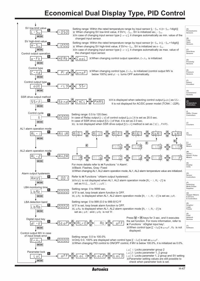
※Whenchangingcontroloutputoperation,ErMVisinitialized.
※ Whenchangingcontroltype,ErMVisinitialized(controloutputMVisbelow100%)andDI-T turnsOFFautomatically.
※Itisdisplayedwhenselectingcontroloutput[OUT]asSSR.ItisnotdisplayedforAC/DCpowermodel(TCN4 -22R).
Settingrange:0.5to120.0sec.IncaseofRelayoutput[RLY]ofcontroloutput[OUT]itissetas20.0sec.IncaseofSSRdriveoutput[SSR]ofthat,itissetas2.0sec.※TisnotdisplayedwhenSSRdriveoutput[SSrM]methodissetasCYCL, PHAS.
Settingrange:0to9999sec.※'0'isset,loopbreakalarmfunctionisOFF.※LBaTisdisplayedwhenAL1,AL2alarmoperationmode[AL-1,AL-2]issetasLBa.
Settingrange:0to999(0.0to999.9)/※'0'isset,loopbreakalarmfunctionisOFF.※ LBaBisdisplayedwhenAL1,AL2alarmoperationmode[AL-1,AL-2]issetasLBa andLBaTisnot'0'.
Settingrange:0.0to100.0%※Only0.0,100%aredisplayedwhencontroltype[C-MD]issetasONOF.※WhenchangingPIDcontroltoON/OFFcontrol,ifMVisbelow100.0%,itisinitializedas0.0%.
Settingrange:Withintheratedtemperaturerangebyinputsensor[L-SV ≤(H-SV-1digit)]※ When changing SV low-limit value, if SV<L-SV, SV is initialized as L-SV.※ Incaseofchanginginputsensortype[IN-T],itchangesautomaticallyasmin.valueofthechangedinputsensor.
Settingrange:Withintheratedtemperaturerangebyinputsensor[H-SV ≥(L-SV+1digit)]※ When changing SV high-limit value, if SV>H-SV, SV is initialized as H-SV.※ Incaseofchanginginputsensortype[IN-T],itchangesautomaticallyasmax.valueofthechangedinputsensor.
Formoredetailsreferto Functions' Alarm'.※Black:Flashes,Gray:Fixed※ WhenchangingAL1,AL2alarmoperationmode,AL1,AL2alarmtemperaturevalueareinitialized.
Press + keysfor3sec.anditexecutesthesetfunction.Formoreinformation,refertoFunctions' Digitalinputkey'.
※Whencontroltype[C-MD]isONOF,ATisnotdisplayed.
LOC1:Locksparametergroup2LOC2:Locksparameter1,2groupLOC3:Locksparameter1,2groupandSVsetting※ Parametersettingvaluesarestillpossibletocheckwhenparameterlockisset.
Referto Functions' Alarmoutputhysteresis'.※ AHYSisnotdisplayedwhenAL1,AL2alarmoperationmode[AL-1,AL-2]issetasAM)_,SBa ,LBa .
SVlow-limitvalue
SVhigh-limitvalue
Controloutputoperation
Controltype
Controloutputtype
SSRdriveoutputmethod
Controlcycle
AL1alarmoperationmode
AL2alarmoperationmode
Alarmoutputhysteresis
LBAmonitoringtime
LBAdetectionband
Digitalinputkey
ControloutputMVincaseofinputbreakerror
Parameterlock
L-SV
H-SV
O-FT
C-MD
OUT
SSrM
AL-1
AL-2
DI-K
LBaB
LBaT
AHYS
T
ErMV
LOC
STND
AM!A
AM@A
STOP
0002
0000
001
02)0
AlRE AT OFF
00)0
OFF LOC1 LOC2 LOC3
CYCL PHAS
-050
1200
HEAT
PID
RLY
COOL
ONOF
SSR
S
S
S
S
S
S
S
S
S
S
S
S
S
S
S
H-48
TCN Series
Factory Default
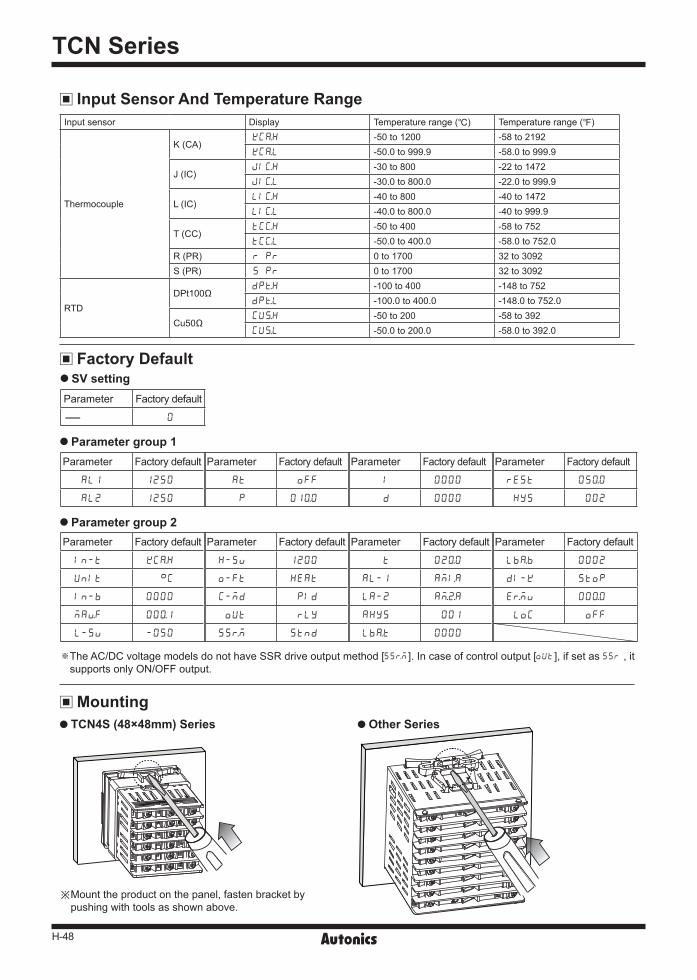
Input Sensor And Temperature RangeInputsensor Display Temperaturerange() Temperaturerange()
Thermocouple
K(CA)KCaH -50to1200 -58to2192KCaL -50.0to999.9 -58.0to999.9
J(IC)JIcH -30to800 -22to1472JIcL -30.0to800.0 -22.0to999.9
L(IC)LIcH -40to800 -40to1472LIcL -40.0to800.0 -40to999.9
T(CC)TCcH -50to400 -58to752TCcL -50.0to400.0 -58.0to752.0
R(PR) R PR 0to1700 32to3092S(PR) S PR 0to1700 32to3092
RTDDPt100Ω
DPtH -100to400 -148to752DPtL -100.0to400.0 -148.0to752.0
Cu50ΩCUsH -50to200 -58to392CUsL -50.0to200.0 -58.0to392.0
Mounting TCN4S (48×48mm) Series Other Series
※Mounttheproductonthepanel,fastenbracketbypushingwithtoolsasshownabove.
Parameter group 1
Parameter group 2
SV setting
Parameter Factorydefault Parameter Factorydefault Parameter Factorydefault Parameter Factorydefault
IN-T KCaH H-SV 1200 T 02)0 LBaB 0002
UNIT ?C O-FT HEAT AL-1 AMiA DI-K STOP
IN-B 0000 C-MD PID LA-2 Am@A ErMV 00)0
MAvF 00)1 OUT RLY AHYS 001 LOC OFF
L-SV -050 SSrM STND LBaT 0000
Parameter Factorydefault Parameter Factorydefault Parameter Factorydefault Parameter Factorydefault
AL1 1250 AT OFF I 0000 REST 05)0
AL2 1250 P 01)0 D 0000 HYS 002
Parameter Factorydefault
- 0
※ TheAC/DCvoltagemodelsdonothaveSSRdriveoutputmethod[SSrM].Incaseofcontroloutput[OUT],ifsetas SSR,itsupportsonlyON/OFFoutput.
H-49
Economical Dual Display Type, PID Control
(A) Photoelectric Sensors
(B) FiberOpticSensors
(C) Door/AreaSensors
(D) ProximitySensors
(E) PressureSensors
(F) RotaryEncoders
(G) Connectors/Sockets
(H)TemperatureControllers
(I)SSRs / PowerControllers
(J) Counters
(K) Timers
(L) PanelMeters
(M)Tacho /Speed / PulseMeters
(N)DisplayUnits
(O)SensorControllers
(P)SwitchingMode PowerSupplies
(Q)Stepper Motors & Drivers & Controllers
(R)Graphic/LogicPanels
(S)FieldNetworkDevices
(T) Software
Functions
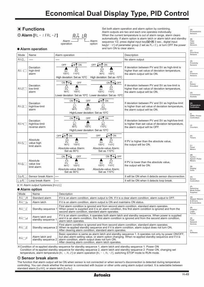
Alarm operation
Alarm [AL-1 / AL-2]Alarm
operationAlarmoption
AM!A
Sensor break alarmThefunctionthatalarmoutputwillbeONwhensensorisnotconnectedorwhensensor'sdisconnectionisdetectedduringtemperaturecontrolling.Youcancheckwhetherthesensorisconnectedwithbuzzerorotherunitsusingalarmoutputcontact.Itisselectablebetweenstandardalarm[SBaA],oralarmlatch[SBaB].
Alarm optionMode Name DescriptionAM .A Standardalarm Ifitisanalarmcondition,alarmoutputisON.Ifitisaclearalarmcondition,alarmoutputisOFF.AM .B Alarmlatch Ifitisanalarmcondition,alarmoutputisONandmaintainsONstatus.
AM .C Standbysequence1Firstalarmconditionisignoredandfromsecondalarmcondition,standardalarmoperates.Whenpowerissuppliedanditisanalarmcondition,thisfirstalarmconditionisignoredandfromthesecondalarmcondition,standardalarmoperates.
AM .DAlarmlatchandstandbysequence1
Ifitisanalarmcondition,itoperatesbothalarmlatchandstandbysequence.Whenpowerissuppliedanditisanalarmcondition,thisfirstalarmconditionisignoredandfromthesecondalarmcondition,alarmlatchoperates.
AM .E Standbysequence2Firstalarmconditionisignoredandfromsecondalarmcondition,standardalarmoperates.Whenre-appliedstandbysequenceandifitisalarmcondition,alarmoutputdoesnotturnON.Afterclearingalarmcondition,standardalarmoperates.
AM .FAlarmlatchandstandbysequence2
Basicoperationissameasalarmlatchandstandbysequence1.ItoperatesnotonlybypowerON/OFF,butalsoalarmsettingvalue,oralarmoptionchanging.Whenre-appliedstandbysequenceandifitisalarmcondition,alarmoutputdoesnotturnON.Afterclearingalarmcondition,alarmlatchoperates.
Mode Name Alarmoperation Description
AM)_ - - Noalarmoutput
AM!
Deviationhigh-limitalarm
SV100
PV110
OFF ONH
PV90
SV100
OFF ONHIfdeviationbetweenPVandSVashigh-limitishigherthansetvalueofdeviationtemperature,thealarmoutputwillbeON.
Highdeviation:Setas10 Highdeviation:Setas-10
AM@
Deviationlow-limitalarm
PV90
SV100
OFFON H
SV100
PV110
OFFON HIfdeviationbetweenPVandSVaslow-limitishigherthansetvalueofdeviationtemperature,thealarmoutputwillbeON.
Lowerdeviation:Setas10 Lowerdeviation:Setas-10
AM#
Deviationhigh/low-limitalarm
PV90
PV110
SV100
OFFON ONH HIfdeviationbetweenPVandSVashigh/low-limitishigherthansetvalueofdeviationtemperature,thealarmoutputwillbeON.
High/Lowerdeviation:Setas10
AM$
Deviationhigh/low-limitreversealarm
PV90
PV110
SV100
OFFON ONH HIfdeviationbetweenPVandSVashigh/low-limitishigherthansetvalueofdeviationtemperature,thealarmoutputwillbeOFF.
High/Lowerdeviation:Setas10
AM%
Absolutevaluehighlimitalarm
PV90
SV100
OFF ONH
SV100
PV110
OFF ONH
IfPVishigherthantheabsolutevalue,theoutputwillbeON.
Absolute-valueAlarm:Setas90
Absolute-valueAlarm:Setas110
AM^
Absolutevaluelowlimitalarm
PV90
SV100
OFFON H
SV100
PV110
OFFON H
IfPVislowerthantheabsolutevalue,theoutputwillbeON.
Absolute-valueAlarm:Setas90
Absolute-valueAlarm:Setas110
SBa SensorbreakAlarm - ItwillbeONwhenitdetectssensordisconnection.LBa LoopbreakAlarm - ItwillbeONwhenitdetectsloopbreak.
※ H:Alarmoutputhysteresis[AHYS]
※Conditionofre-appliedstandbysequenceforstandbysequence1,alarmlatchandstandbysequence1:PowerONConditionofre-appliedstandbysequenceforstandbysequence2,alarmlatchandstandbysequence2:PowerON,changingsettemperature,alarmtemperature[AL1,AL2]oralarmoperation[AL-1,AL-2],switchingSTOPmodetoRUNmode.
Setbothalarmoperationandalarmoptionbycombining.Alarmoutputsaretwoandeachoneoperatesindividually.Whenthecurrenttemperatureisoutofalarmrange,alarmclearsautomatically.Ifalarmoptionisalarmlatchoralarmlatchandstandbysequence1/2,pressdigitalinputkey( + 3sec.,digitalinputkey[DI-K]ofparametergroup2setasAlRE),orturnOFFthepowerandturnONtoclearalarm.
H-50
TCN Series
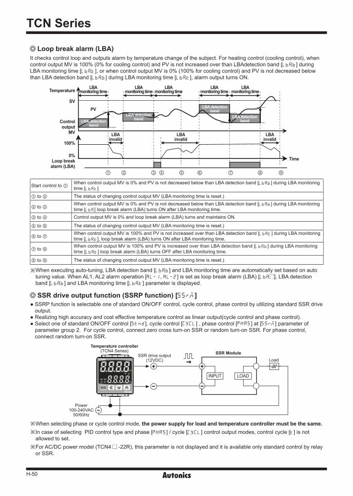
Loop break alarm (LBA) Itcheckscontrolloopandoutputsalarmbytemperaturechangeofthesubject.Forheatingcontrol(coolingcontrol),whencontroloutputMVis100%(0%forcoolingcontrol)andPVisnotincreasedoverthanLBAdetectionband[LBaB]duringLBAmonitoringtime[LBaT],orwhencontroloutputMVis0%(100%forcoolingcontrol)andPVisnotdecreasedbelowthanLBAdetectionband[LBaB]duringLBAmonitoringtime[LBaT],alarmoutputturnsON.
Startcontrolto① WhencontroloutputMVis0%andPVisnotdecreasedbelowthanLBAdetectionband[LBaB]duringLBAmonitoringtime[LBaT]
① to ② ThestatusofchangingcontroloutputMV(LBAmonitoringtimeisreset.)
② to ③ WhencontroloutputMVis0%andPVisnotdecreasedbelowthanLBAdetectionband[LBaB]duringLBAmonitoringtime[LBa]loopbreakalarm(LBA)turnsONafterLBAmonitoringtime.
③ to ④ ControloutputMVis0%andloopbreakalarm(LBA)turnsandmaintainsON.
④ to ⑥ ThestatusofchangingcontroloutputMV(LBAmonitoringtimeisreset.)
⑥ to ⑦ WhencontroloutputMVis100%andPVisnotincreasedoverthanLBAdetectionband[LBaT]duringLBAmonitoringtime[LBaT],loopbreakalarm(LBA)turnsONafterLBAmonitoringtime.
⑦ to ⑧ WhencontroloutputMVis100%andPVisincreasedoverthanLBAdetectionband[LBaB]duringLBAmonitoringtime[LBaT]loopbreakalarm(LBA)turnsOFFafterLBAmonitoringtime.
⑧ to ⑨ ThestatusofchangingcontroloutputMV(LBAmonitoringtimeisreset.)
※Whenexecutingauto-tuning,LBAdetectionband[LBaB]andLBAmonitoringtimeareautomaticallysetbasedonautotuningvalue.WhenAL1,AL2alarmoperation[AL-1,AL-2]issetasloopbreakalarm(LBA)[LBa ],LBAdetectionband[LBaB]andLBAmonitoringtime[LBaT]parameterisdisplayed.
Temperature
SV
LBAmonitoring time
PV
LBA detectionband
LBA detectionband
LBA detectionband
LBA detectionband
LBAinvalid
LBAinvalid
LBAinvalid
LBAmonitoring time
LBAmonitoring time
LBAmonitoring time
LBAmonitoring time
Controloutput
MV
100%
Time
① ② ③ ④ ⑤ ⑥ ⑦ ⑧ ⑨
0%Loop breakalarm (LBA)
SSRdriveoutput(12VDC)
INPUT LOAD
Load
Power100-240VAC50/60Hz
Temperature controller(TCN4Series) SSR Module
※Whenselectingphaseorcyclecontrolmode,the power supply for load and temperature controller must be the same.※ IncaseofselectingPIDcontroltypeandphase[PHAS]/cycle[CYCL]controloutputmodes,controlcycle[T]isnotallowedtoset.
※ ForAC/DCpowermodel(TCN4 -22R),thisparameterisnotdisplayedanditisavailableonlystandardcontrolbyrelayorSSR.
SSRPfunctionisselectableoneofstandardON/OFFcontrol,cyclecontrol,phasecontrolbyutilizingstandardSSRdriveoutput.
Realizinghighaccuracyandcosteffectivetemperaturecontrolaslinearoutput(cyclecontrolandphasecontrol).SelectoneofstandardON/OFFcontrol[STND],cyclecontrol[CYCL],phasecontrol[PHAS]at[SSrM]parameterofparametergroup2.Forcyclecontrol,connectzerocrossturn-onSSRorrandomturn-onSSR.Forphasecontrol,connectrandomturn-onSSR.
SSR drive output function (SSRP function) [SSrM]
H-51
Economical Dual Display Type, PID Control
(A) Photoelectric Sensors
(B) FiberOpticSensors
(C) Door/AreaSensors
(D) ProximitySensors
(E) PressureSensors
(F) RotaryEncoders
(G) Connectors/Sockets
(H)TemperatureControllers
(I)SSRs / PowerControllers
(J) Counters
(K) Timers
(L) PanelMeters
(M)Tacho /Speed / PulseMeters
(N)DisplayUnits
(O)SensorControllers
(P)SwitchingMode PowerSupplies
(Q)Stepper Motors & Drivers & Controllers
(R)Graphic/LogicPanels
(S)FieldNetworkDevices
(T) Software
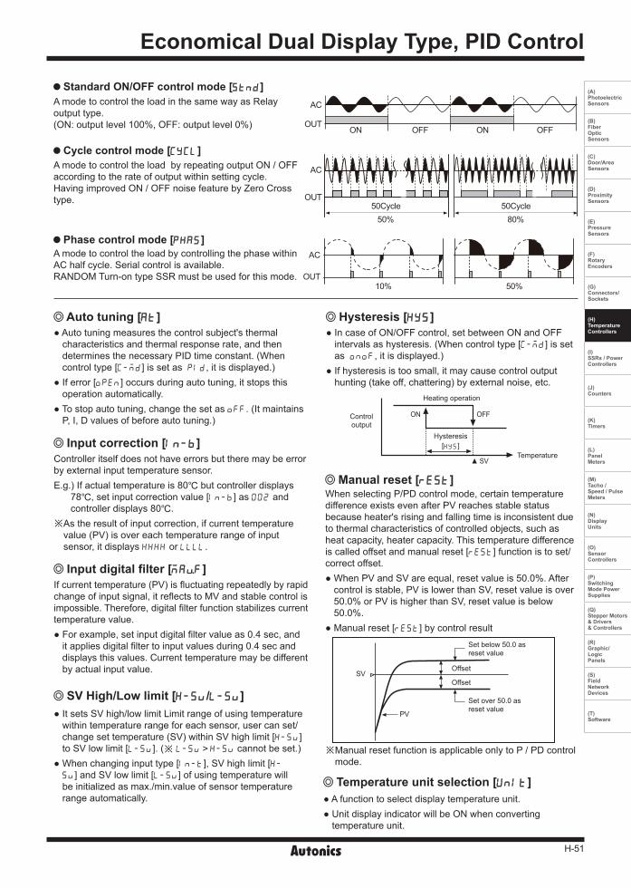
Standard ON/OFF control mode [STND]
Cycle control mode [CYCL]
Phase control mode [PHAS]
A mode to control the load in the same way as Relay output type. (ON: output level 100%, OFF: output level 0%)
A mode to control the load by repeating output ON / OFF according to the rate of output within setting cycle. Having improved ON / OFF noise feature by Zero Cross type.
A mode to control the load by controlling the phase within AC half cycle. Serial control is available.RANDOM Turn-on type SSR must be used for this mode.
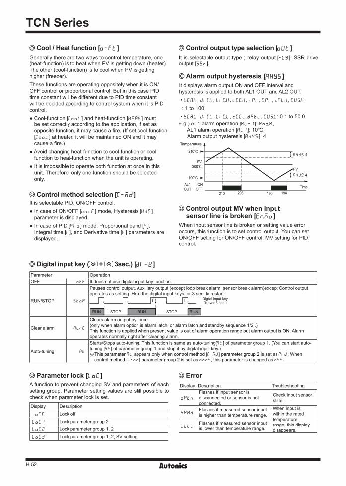
Heating operation
Controloutput
ON OFF
SVTemperature
Hysteresis[HYS]
Auto tuning [AT] Hysteresis [HYS] Auto tuning measures the control subject's thermal
characteristics and thermal response rate, and then determines the necessary PID time constant. (When control type [C-MD] is set as PID, it is displayed.)
If error [OPEN] occurs during auto tuning, it stops this operation automatically.
To stop auto tuning, change the set as OFF. (It maintains P, I, D values of before auto tuning.)
In case of ON/OFF control, set between ON and OFF intervals as hysteresis. (When control type [C-MD] is set as ONOF, it is displayed.)
If hysteresis is too small, it may cause control output hunting (take off, chattering) by external noise, etc.
Manual reset [REST]When selecting P/PD control mode, certain temperature difference exists even after PV reaches stable status because heater's rising and falling time is inconsistent due to thermal characteristics of controlled objects, such as heat capacity, heater capacity. This temperature difference is called offset and manual reset [REST] function is to set/correct offset. When PV and SV are equal, reset value is 50.0%. After
control is stable, PV is lower than SV, reset value is over 50.0% or PV is higher than SV, reset value is below 50.0%.
Manual reset [REST] by control result
Temperature unit selection [UNIT] A function to select display temperature unit. Unit display indicator will be ON when converting
temperature unit.
Input correction [IN-B]Controller itself does not have errors but there may be error by external input temperature sensor.E.g.) If actual temperature is 80 but controller displays
78, set input correction value [IN-B] as 002 and controller displays 80.
※As the result of input correction, if current temperature value (PV) is over each temperature range of input sensor, it displays HHHH or LLLL.
Input digital filter [MAvF]If current temperature (PV) is fluctuating repeatedly by rapid change of input signal, it reflects to MV and stable control is impossible. Therefore, digital filter function stabilizes current temperature value. For example, set input digital filter value as 0.4 sec, and
it applies digital filter to input values during 0.4 sec and displays this values. Current temperature may be different by actual input value.
SV High/Low limit [H-SV/L-SV] It sets SV high/low limit Limit range of using temperature
within temperature range for each sensor, user can set/change set temperature (SV) within SV high limit [H-SV] to SV low limit [L-SV]. (※ L-SV>H-SV cannot be set.)
When changing input type [IN-T], SV high limit [H-
SV] and SV low limit [L-SV] of using temperature will be initialized as max./min.value of sensor temperature range automatically.
50Cycle 50Cycle50% 80%
AC
OUT
ON ONOFF OFF
AC
OUT
SV
PV
Offset
Set below 50.0 asreset value
Set over 50.0 asreset value
Offset
※Manual reset function is applicable only to P / PD control mode.
10% 50%
AC
OUT
H-52
TCN Series
Display Description Troubleshooting
OPEN
Flashesifinputsensorisdisconnectedorsensorisnotconnected.
Checkinputsensorstate.
HHHHFlashesifmeasuredsensorinputishigherthantemperaturerange.
Wheninputiswithintheratedtemperaturerange,thisdisplaydisappears.
LLLLFlashesifmeasuredsensorinputislowerthantemperaturerange.
Display Description
OFF Lockoff
LOC1 Lockparametergroup2
LOC2 Lockparametergroup1,2
LOC3 Lockparametergroup1,2,SVsetting
Cool / Heat function [O-FT]
Parameter lock [LOC] Error
Control output MV when input sensor line is broken [ErMV]
Control method selection [C-MD] ItisselectablePID,ON/OFFcontrol.IncaseofON/OFF[ONOF]mode,Hysteresis[HYS]parameterisdisplayed.
IncaseofPID[PID]mode,Proportionalband[P],Integraltime[I],andDerivativetime[T]parametersaredisplayed.
AfunctiontopreventchangingSVandparametersofeachsettinggroup.Parametersettingvaluesarestillpossibletocheckwhenparameterlockisset.
Generallytherearetwowaystocontroltemperature,one(heat-function)istoheatwhenPVisgettingdown(heater).Theother(cool-function)istocoolwhenPVisgettinghigher(freezer).ThesefunctionsareoperatingoppositelywhenitisON/OFFcontrolorproportionalcontrol.ButinthiscasePIDtimeconstantwillbedifferentduetoPIDtimeconstantwillbedecidedaccordingtocontrolsystemwhenitisPIDcontrol.Cool-function[COOL]andheat-function[HEAT]mustbesetcorrectlyaccordingtotheapplication,ifsetasoppositefunction,itmaycauseafire.(Ifsetcool-function[COOL]atheater,itwillbemaintainedONanditmaycauseafire.)
Avoidchangingheat-functiontocool-functionorcool-functiontoheat-functionwhentheunitisoperating.
Itisimpossibletooperatebothfunctionatonceinthisunit.Therefore,onlyonefunctionshouldbeselectedonly.
Wheninputsensorlineisbrokenorsettingvalueerroroccurs,thisfunctionistosetcontroloutput.YoucansetON/OFFsettingforON/OFFcontrol,MVsettingforPIDcontrol.
Alarm output hysteresis [AHYS] ItdisplaysalarmoutputONandOFFintervalandhysteresisisappliedtobothAL1OUTandAL2OUT.•KCaH, JIcH, LIcH, TCcH, RPR, SPR, DPtH,CUsH
:1to100•KCaL, JIcL, LIcL, TCcL,DPtL,CUsL:0.1to50.0E.g.)AL1alarmoperation[AL-1]:AM#A,AL1alarmoperation[AL1]:10, Alarmoutputhysteresis[AHYS]:4
210
190
Temperature
SV200
ONOFF
AL1OUT
210 206 190 194
:4
:4PV
Time
Digital input key ( + 3sec.) [DI-K]
Control output type selection [OUT] It isselectableoutput type;relayoutput [RLY],SSRdriveoutput[SSR].
Parameter OperationOFF OFF Itdoesnotusedigitalinputkeyfunction.
RUN/STOP STOP
Pausescontroloutput.Auxiliaryoutput(exceptloopbreakalarm,sensorbreakalarm)exceptControloutputoperatesassetting.Holdthedigitalinputkeysfor3sec.torestart.
RUN RUN
t t tt
STOP STOP RUN
Digitalinputkey(t:over3sec.)
Clearalarm AlRE
Clearsalarmoutputbyforce.(onlywhenalarmoptionisalarmlatch,oralarmlatchandstandbysequence1/2.)ThisfunctionisappliedwhenpresentvalueisoutofalarmoperationrangebutalarmoutputisON.Alarmoperatesnormallyrightafterclearingalarm.
Auto-tuning AT
Starts/Stopsauto-tuning.Thisfunctionissameasauto-tuning[AT]ofparametergroup1.(Youcanstartauto-tuning[AT]ofparametergroup1andstopitbydigitalinputkey.)※ ThisparameterATappearsonlywhencontrolmethod[C-MD]parametergroup2issetasPID.Whencontrolmethod[C-MD]parametergroup2issetasONOF,thisparameterischangedasOFF.
H-53
Economical Dual Display Type, PID Control
(A) Photoelectric Sensors
(B) FiberOpticSensors
(C) Door/AreaSensors
(D) ProximitySensors
(E) PressureSensors
(F) RotaryEncoders
(G) Connectors/Sockets
(H)TemperatureControllers
(I)SSRs / PowerControllers
(J) Counters
(K) Timers
(L) PanelMeters
(M)Tacho /Speed / PulseMeters
(N)DisplayUnits
(O)SensorControllers
(P)SwitchingMode PowerSupplies
(Q)Stepper Motors & Drivers & Controllers
(R)Graphic/LogicPanels
(S)FieldNetworkDevices
(T) Software
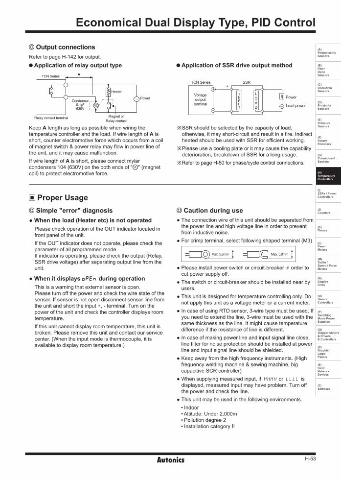
Output connectionsRefertopageH-142foroutput.
Application of relay output type
KeepAlengthaslongaspossiblewhenwiringthetemperaturecontrollerandtheload.IfwirelengthofAisshort,counterelectromotiveforcewhichoccursfromacoilofmagnetswitch&powerrelaymayflowinpowerlineoftheunit,anditmaycausemalfunction.IfwirelengthofAisshort,pleaseconnectmylarcondensers104(630V)onthebothendsof" "(magnetcoil)toprotectelectromotiveforce.
Voltageoutputterminal
TCNSeries SSR
Loadpower
Power
+
-
INPUT
LOAD
※ SSRshouldbeselectedbythecapacityofload,otherwise,itmayshort-circuitandresultinafire.IndirectheatedshouldbeusedwithSSRforefficientworking.
※ Pleaseuseacoolingplateoritmaycausethecapabilitydeterioration,breakdownofSSRforalongusage.
※ RefertopageH-50forphase/cyclecontrolconnections.
Application of SSR drive output method
When the load (Heater etc) is not operatedPleasecheckoperationoftheOUTindicatorlocatedinfrontpaneloftheunit.IftheOUTindicatordoesnotoperate,pleasechecktheparameterofallprogrammedmode.Ifindicatorisoperating,pleasechecktheoutput(Relay,SSRdrivevoltage)afterseparatingoutputlinefromtheunit.
When it displays OPEN during operationThisisawarningthatexternalsensorisopen.Pleaseturnoffthepowerandcheckthewirestateofthesensor.Ifsensorisnotopendisconnectsensorlinefromtheunitandshorttheinput+,-terminal.Turnonthepoweroftheunitandcheckthecontrollerdisplaysroomtemperature.Ifthisunitcannotdisplayroomtemperature,thisunitisbroken.Pleaseremovethisunitandcontactourservicecenter.(Whentheinputmodeisthermocouple,itisavailabletodisplayroomtemperature.)
Proper Usage Simple "error" diagnosis
Theconnectionwireofthisunitshouldbeseparatedfromthepowerlineandhighvoltagelineinordertopreventfrominductivenoise. Forcrimpterminal,selectfollowingshapedterminal(M3)
Max.5.8mm Max.5.8mm
Pleaseinstallpowerswitchorcircuit-breakerinordertocutpowersupplyoff. Theswitchorcircuit-breakershouldbeinstallednearbyusers. Thisunitisdesignedfortemperaturecontrollingonly.Donotapplythisunitasavoltagemeteroracurrentmeter. IncaseofusingRTDsensor,3-wiretypemustbeused.Ifyouneedtoextendtheline,3-wiremustbeusedwiththesamethicknessastheline.Itmightcausetemperaturedifferenceiftheresistanceoflineisdifferent. Incaseofmakingpowerlineandinputsignallineclose,linefilterfornoiseprotectionshouldbeinstalledatpowerlineandinputsignallineshouldbeshielded. Keepawayfromthehighfrequencyinstruments.(Highfrequencyweldingmachine&sewingmachine,bigcapacitiveSCRcontroller) Whensupplyingmeasuredinput,ifHHHHorLLLLisdisplayed,measuredinputmayhaveproblem.Turnoffthepowerandchecktheline. Thisunitmaybeusedinthefollowingenvironments.
Indoor Altitude:Under2,000m Pollutiondegree2 InstallationcategoryⅡ
Caution during use
TCNSeries A
Relaycontactterminal
Heater
PowerCondenser
0.1630V
MagnetorRelaycontact
Recommended