Basin Sweeping Options CTS
Separators and Filtration Solutions
Page 5
LAKOS is a proud member of the U.S. Green Building Council
Exceeds industry specifications for keeping cooling water systems free of troublesome contaminants. Removes particles and floating debris. Controls build-up in tower basins and remote sumps. Helps maintain optimum operating conditions for reduced maintenance, servicing, downtime, energy costs, water loss and enhances chemical performance.
LAKOS CTS Tower System Media Filters are designed exclusively for the demands of cooling tower operations. Filtration down to 5 micron is available as standard. Options for filtration down to 0.5 micron are available (consult factory). Either for side stream or full stream applications, Tower System Media Filters offer a full range of systems to meet your specific needs. High pressure ratings and ASME code options are available, please contact the factory.
Filtration efficiency of 90% removal by volume of particles down to 5 micron
Uniform, high porosity media for consistent, reliable performance at a low pressure loss.
Epoxy-coated carbon steel tanks
Durable, long-lasting and affordable.
Backwash options
Durable butterfly valves, mechanically linked via heavy-duty linkage rods operated by either pneumatic or electric actuators. Piping configurations for backwashing with system water or city/other water source.
Effective underdrain design
Encourages uniform flow through the sand media. Low pressure loss. Field-serviceable. Provides uniform backwashing for thorough media cleaning cycles. Prevents residual build-up and excessive backwash frequency.
Packaged Carbon Tank Systems (CTS) Include:
Filter vessel, valves, NEMA 4x - UL Listed Control Panel, end-suction single stage, TEFC motor; centrifugal pump (electric motor driven), and piping on a rigid skid. Standard 5 micron media is included as standard. Refer to page 2 for more details.
Flow range: 192 - 1,006 U.S. gpm(43 - 229 m3/hr)
For higher flow rates, consult factory
Tank sizes:42" to 96" diameter@ 20 U.S. gpm/sq. ft.(4.5 m3/hr)
Tower System Media FiltersCarbon Tank System (CTS)Carbon Steel Epoxy Coated Media Filters for Cooling Towers
Includes pump, piping, and skid
90-Inch Model Shown Here
Limited Warranty
Basic Specifications
1365 North Clovis Avenue
Fresno, California 93727 USA
Telephone: (559) 255-1601
FAX: (559) 255-8093
Toll Free: (800) 344-7205
(USA, Mexico and Canada)
Internet: www.lakos.com
E-mail: [email protected] on recycled paper LS-720D (rev. 1/11)
All products manufactured and marketed by this corporation are warranted to be free of defects in material or workmanship for 12 months from date of installation; if installed 6 months or more after ship date, warranty shall be a maximum of 18 months from ship date.
If a fault develops, notify us, giving a complete description of the alleged malfunction. Include the model number(s), date of delivery and operating conditions of subject product(s). We will subsequently review this information and, at our option, supply you with either servicing data or shipping instruction and returned materials authorization. Upon prepaid receipt of subject product(s) at the instructed destination, we will then either repair or replace such product(s), at our option, and if determined to be a warranted defect, we will perform such necessary product repairs or replace such product(s) at our expense.
This limited warranty does not cover any products, damages or injuries resulting from misuse, neglect, normal expected wear, chemically-caused corrosion, improper installation or operation contrary to factory recommendation. Nor does it cover equipment that has been modified, tampered with or altered without authorization.
No other extended liabilities are stated or implied and this warranty in no event covers incidental or consequential damages, injuries or costs resulting from any such defective product(s).
Lakos Separators are manufactured and sold under one or more of the following U.S. Patents:5,320,747; 5,338,341; 5,368,735; 5,425,876; 5,571,416; 5,578,203; 5,622,545; 5,653,874; 5,894,995; 6,090,276; 6,143,175; 6,167,960; 6,202,543; 7,000,782; 7,032,760 and corresponding foreign patents, other U.S. and foreign patents pending.
Filtration Type & PerformanceThe removal of specific unwanted contaminants from a pumped/pressurized fluid flow system shall be accomplished with a sand media filtration package. Performance shall be specified for particulate as fine as 2 microns, based on the specific sand media supplied.
Filtration System Design & FunctionSystem shall be designed/sized for a flow rate of 20 gallons per minute per square foot of filter media surface area.
A system-matched pump directs the fluid through a butterfly valve into the inlet of a sand media filter tank. Flow is evenly distributed across the sand media bed, allowing the fluid to pass through the sand media and capturing the contaminants on the surface and upper layer of the sand media. Fluid flow continues through the sand media to the filter tank’s integral underdrain, directing water to the filter system’s outlet.
The underdrain shall feature a full-size manifold with serviceable removal lateral design to ensure that filter flow and backwash flow are uniform across and throughout the sand media bed.
Each unit shall be equipped with a man-way located on the top of the unit, and on the tank side. A pressure gauge and air relief assembly shall also be provided.
Backwashing/Contaminant RemovalThe accumulation of contaminants on the sand media surface shall be monitored via pressure differential from inlet to outlet. At a prescribed pressure differential or a given period of time or operator discretion, the filter system shall backwash the captured contaminants to desired waste. This function shall be a) automatically controlled via a pressure differential gauge and clock timer, or b) manual, monitored and initiated by an operator.
The butterfly valve at the inlet shall be actuated pneumatically or electrically to interrupt system flow and provide a backwash discharge outlet. Backwash flow shall come from either a) the system flow, redirected through filter tank’s outlet and underdrain, or b) a separate flow source, such as city water, directed through the filter tank’s outlet and underdrain.
Backwash flow and pressure shall be sufficient to fluidize the sand media bed and cause the surface contaminants to rise in suspension and discharge via the flanged butterfly valve to desired waste.
Upon completion of the backwashing cycle, the inlet’s butterfly valve shall again return to its operating position, allowing system flow to enter the filter tank, simultaneously interrupting backwash discharge. This allows the sand media bed to again settle, forming the filtration surface for further contaminant removal.
Filter System DetailsA. Inlet shall be flanged 150# or grooved rated size: __________
B. Outlet shall be flanged 150# or grooved rated connection, size: ________
C. Backwash discharge outlet shall be flanged 150# or grooved rated connection, size: __________
D. Backwash supply line (if not using redirected system flow) shall be flanged 150# or grooved rated connection, size: ___________
E. The filter system shall operate at a flow rate of: __________
Filter System ConstructionFilter tank – ASTM-carbon-steel, all welded construction, with flanged or grooved inlet / outlet, threaded drain and air release connections. Tank shall be suitable for a working pressure of 80 psi on 48" and smaller, and 50 PSI on 54" and larger. Higher pressure rating and/or ASME Code available as an option. The tank will be provided with an epoxy interior lining and two coats of enamel paint on the exterior.
Overdrain/Underdrain – Schedule 80 PVC pipe.
Piping:
CTS-48" and smaller – Galvanized steel with grooved coupling.
CTS-54" and larger – Carbon steel welded.
Pump – End-suction, single stage; TEFC motor; cast iron housing; iron impeller; bronze shaft sleeve; BUNA-N mechanical shaft seal. Pump to be rated for 20 gallons per square foot of filter media surface area at 50 feet TDH. Flooded suction required.
Backwash valves – Butterfly valves; Ductile iron bodies; EPDM valve seats; 416 series stainless steel shaft; Nickel plated ductile iron disc. Valves shall be mechanically linked via heavy duty linkage rods.
Actuator are as follows:
Pneumatic – Actuators shall be driven by floating stem pneumatic actuator with spring return diaphragm for fail safe operation (CTS-54 & larger). A minimum 15 psi air supply is required for operation.
Electrical – Actuators shall be electric and shall incorporate an electric brake to prevent back-drive (CTS-42 & CTS-48).
Pressure Gauges – The filter shall have inlet and outlet pressure gauges.
Control Panel – IEC starter with overload module; HOA selector switch; NEMA-4X enclosure; UL listed; re-set/disconnect/trip switch; 120 volt, single phase control voltage; manual backwash switch; pressure differential switch (factory set to backwash filter); backwash cycle timer; 24-hour backwash clock.
Filter media:
Multi Media (standard) – Filtration efficiency of 90% removal by volume of particles 5 micron and larger (MediaGem 475 + MediaGem 55).
Multi Media (optional) – Filtration down to 0.5 micron consult factory for system design/selection based on specific application and filtration efficiency.
Skid – Carbon steel with epoxy coating (CTS-54 & larger).
StainlessSteel - 3/16-inch minimum thickness (CTS-42 & CTS-48)
PLC Option - Allen Bradley “Pico” PLC (Standard)
• Programmable logic relay• Pre-programmed at factory• Can be programmed for multiple operating/monitoring functions
Consult Lakos for applications and more information.
CTS
HydroBoosters
Flow boosted to 6 U.S. gpmthrough HydroBooster
1 U.S. gpmenters
HydroBoosterModelConnection
Size (inches)Extension Size
(minimum)Flow
Input and Output
Directed turbulence maximizes cleaning efficiency in the tower basin/remote sump. LAKOS HydroBoosters provide turbulence with patented vortexing action as shown. Swivel clips are available as shown in the picture below. Many cooling tower manufacturers offer factory-installed basin sweeping piping. Please consult LAKOS for proper equipment selection. Backwash/Holding tank options available – consult your LAKOS representative.
NOTE: These flow rates are based on an input pressure of 20 psi (1.4 bar) Minimum water level above centerline of HydroBooster should be 2 inches
* This is a flat-fan spray nozzle (brass) for use in applications with a shallow deck in the basin. May be combined with HydroBoosters
HB-10-K 3/4" male NPT 3/4" 10 US gpm and 60 US gpm 2 m3/hr and 12 m3/hr
HB-18-K 3/4" male NPT 1" 18 US gpm and 108 US gpm 4 m3/hr and 24 m3/hr
HB-35-K 1" male NPT 1 1/4" 35 US gpm and 210 US gpm 8 m3/hr and 48 m3/hr
*TSN-0025-B 1/4" male NPT — 4.2 US gpm 1 m3/hr
HydroBoosters in action
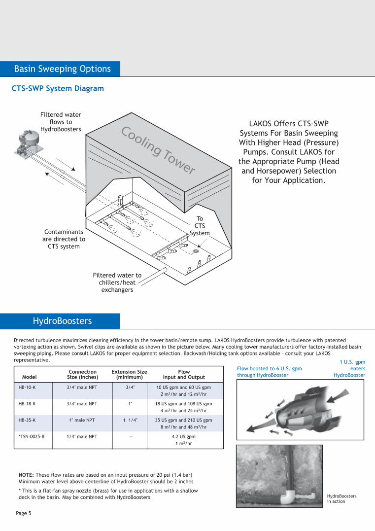
CTS-SWP System Diagram
LAKOS Offers CTS-SWP Systems For Basin Sweeping With Higher Head (Pressure) Pumps. Consult LAKOS for
the Appropriate Pump (Head and Horsepower) Selection
for Your Application.
Cooling Tower
Filtered water to chillers/heat exchangers
ToCTS
SystemContaminants are directed to
CTS system
Filtered water flows to
HydroBoosters
Filter Outlet
CentrifugalPump and Motor
*Two (2) PneumaticActuated Butterfly Valves
with PremiumLinkage Assembly
BackwashOutlet Automatic
Air Vent
Pump Inlet
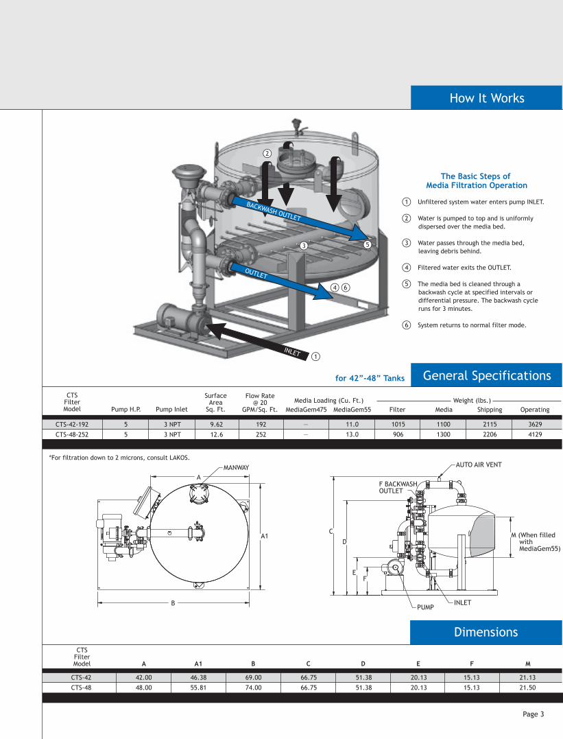
CTS System Diagram(CTS-54 and Larger)
CTS System Diagram(CTS-48 and Smaller)
for 42”-48” Tanks
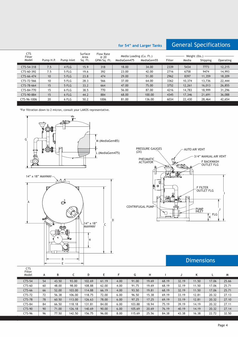
The Basic Steps of Media Filtration Operation
*CTS units up to the CTS-48 model have electrical actuators, while larger units have the pneumatic actuator shown above Page 4
Pump H.P. Pump Inlet
SurfaceArea
Sq. Ft.
Flow Rate@ 20
GPM/Sq. Ft. MediaGem475Media Loading (Cu. Ft.) Weight (lbs.)
MediaGem55 Filter Media Shipping
How It WorksStandard ConfigurationCTS
FilterModel
CTS-54-318
CTS-60-392
CTS-66-474
CTS-72-566
CTS-78-664
CTS-84-770
CTS-90-884
CTS-96-1006
7.5
7.5
10
10
15
15
15
20
4 FLG
5 FLG
5 FLG
5 FLG
5 FLG
6 FLG
6 FLG
6 FLG
15.9
19.6
23.8
28.3
33.2
38.5
44.2
50.2
318
392
474
566
664
770
884
1006
A
54
60
66
72
78
84
90
96
E
61.19
62.00
66.19
72.00
78.00
84.00
90.00
96.00
G
91.00
91.75
93.50
96.50
97.25
103.88
105.69
115.69
F
4.00
4.00
4.00
6.00
6.00
6.00
6.00
8.00
B
43.50
48.00
52.00
56.38
60.50
66.50
71.00
77.50
C
93.00
98.00
103.00
106.00
113.00
118.18
126.18
142.50
D
102.69
108.88
114.88
118.75
126.63
131.81
140.69
156.75
H
19.69
19.69
19.81
15.38
17.25
18.94
20.69
25.56
I
68.19
68.19
68.19
69.19
69.19
75.19
76.19
84.38
J
32.19
32.19
32.19
33.19
33.19
39.19
40.19
43.38
K
11.50
11.50
11.50
12.81
12.81
14.19
14.19
16.38
L
17.06
17.06
17.06
20.32
20.32
20.32
20.32
22.72
M
25.66
25.71
25.71
27.13
27.10
27.11
27.14
32.50
18.00
23.00
29.00
37.00
47.00
56.00
68.00
81.00
34.00
42.00
51.00
64.00
75.00
87.00
100.00
136.00
2339
2716
2962
3362
3752
4216
4345
6034
5434
6758
8397
10,374
12,261
14,783
17,346
22,430
7773
9474
11,359
13,736
16,013
18,999
21,691
28,464
Operating
12,215
14,993
18,209
22,444
26,855
31,296
36,088
42,654
CTSFilterModel
CTS-54
CTS-60
CTS-66
CTS-72
CTS-78
CTS-84
CTS-90
CTS-96
Dimensions
*For filtration down to 2 micron, consult your LAKOS representative.
PRESSURE GAUGES(2X)
AUTO AIR VENT
3/4” MANUAL AIR VENT
F BACKWASHOUTLET FLG
F FILTEROUTLET FLG
CENTRIFUGAL PUMPPUMPINLET
FLG
I
J
K
PNEUMATICACTUATOR
M (MediaGem85)G
L (MediaGem475)
A C FB D E
General Specifications
42.00
48.00
A1
46.38
55.81
66.75
66.75
15.13
15.13
M
21.13
21.50
69.00
74.00
51.38
51.38
20.13
20.13
CTSFilterModel
CTS-42
CTS-48
Dimensions
F BACKWASHOUTLET
AUTO AIR VENT
M (When filled with MediaGem55)
PUMP
C
D
EF
INLET
14” x 18” MANWAY
14” x 18”MANWAY C
H
B
A
D
E
Page 2 Page 3
General Specifications
Pump H.P. Pump Inlet
SurfaceArea
Sq. Ft.
Flow Rate@ 20
GPM/Sq. Ft. MediaGem475Media Loading (Cu. Ft.) Weight (lbs.)
MediaGem55 Filter Media Shipping
CTSFilterModel
CTS-42-192
CTS-48-252
5
5
3 NPT
3 NPT
9.62
12.6
192
252
—
—
11.0
13.0
1015
906
1100
1300
2115
2206
3629
4129
Operating
*For filtration down to 2 microns, consult LAKOS.
Auto VentBackwash
Outlet
Grooved-Type CouplingFor Ease of Installation
and Maintenance
Manway (Top)
Manway (Top and Side)
NEMA 4X / UL ListedControl Panel
with PLC Option Available
Four (4) Mechanically-Linked, Electrically-ActivatedButterfly Valves with
Premium Linkage Assembly and Single Actuator
CentrifugalPump and Motor
Pump Inlet Filter Outlet
Epoxy coated, carbon steel vessel
PVCV-Slotted
Underdrain
304 Stainless Steel Mounting Skid
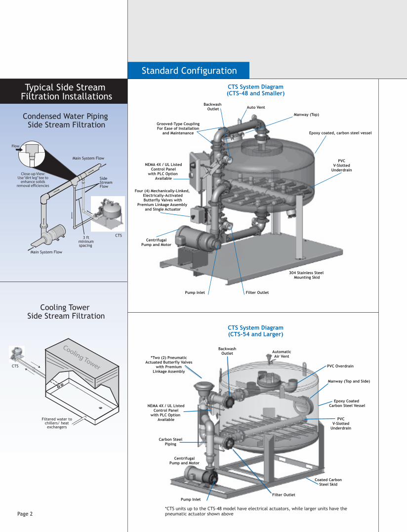
Typical Side Stream Filtration Installations
B
A
A1
INLET
OUTLET
BACKWASH OUTLET
for 54” and Larger Tanks
Filtered water to chillers/ heat exchangers
Close-up View:Use “dirt leg” tee to
enhance solidsremoval efficiencies
Flow
Main System Flow
CTS
CTS
Main System Flow
SideStreamFlow
3 ftmininumspacing
Condensed Water Piping Side Stream Filtration
Cooling Tower Side Stream Filtration
NEMA 4X / UL ListedControl Panel
with PLC Option Available
Coated CarbonSteel Skid
Carbon SteelPiping
Epoxy Coated Carbon Steel Vessel
PVCV-Slotted
Underdrain
PVC Overdrain
Cooling Tower
�
�
�
�
�
�
1 Unfiltered system water enters pump INLET.
2 Water is pumped to top and is uniformly dispersed over the media bed.
3 Water passes through the media bed, leaving debris behind.
4 Filtered water exits the OUTLET.
5 The media bed is cleaned through a backwash cycle at specified intervals or differential pressure. The backwash cycle runs for 3 minutes.
6 System returns to normal filter mode.
MANWAY
Filter Outlet
CentrifugalPump and Motor
*Two (2) PneumaticActuated Butterfly Valves
with PremiumLinkage Assembly
BackwashOutlet Automatic
Air Vent
Pump Inlet
CTS System Diagram(CTS-54 and Larger)
CTS System Diagram(CTS-48 and Smaller)
for 42”-48” Tanks
The Basic Steps of Media Filtration Operation
*CTS units up to the CTS-48 model have electrical actuators, while larger units have the pneumatic actuator shown above Page 4
Pump H.P. Pump Inlet
SurfaceArea
Sq. Ft.
Flow Rate@ 20
GPM/Sq. Ft. MediaGem475Media Loading (Cu. Ft.) Weight (lbs.)
MediaGem55 Filter Media Shipping
How It WorksStandard ConfigurationCTS
FilterModel
CTS-54-318
CTS-60-392
CTS-66-474
CTS-72-566
CTS-78-664
CTS-84-770
CTS-90-884
CTS-96-1006
7.5
7.5
10
10
15
15
15
20
4 FLG
5 FLG
5 FLG
5 FLG
5 FLG
6 FLG
6 FLG
6 FLG
15.9
19.6
23.8
28.3
33.2
38.5
44.2
50.2
318
392
474
566
664
770
884
1006
A
54
60
66
72
78
84
90
96
E
61.19
62.00
66.19
72.00
78.00
84.00
90.00
96.00
G
91.00
91.75
93.50
96.50
97.25
103.88
105.69
115.69
F
4.00
4.00
4.00
6.00
6.00
6.00
6.00
8.00
B
43.50
48.00
52.00
56.38
60.50
66.50
71.00
77.50
C
93.00
98.00
103.00
106.00
113.00
118.18
126.18
142.50
D
102.69
108.88
114.88
118.75
126.63
131.81
140.69
156.75
H
19.69
19.69
19.81
15.38
17.25
18.94
20.69
25.56
I
68.19
68.19
68.19
69.19
69.19
75.19
76.19
84.38
J
32.19
32.19
32.19
33.19
33.19
39.19
40.19
43.38
K
11.50
11.50
11.50
12.81
12.81
14.19
14.19
16.38
L
17.06
17.06
17.06
20.32
20.32
20.32
20.32
22.72
M
25.66
25.71
25.71
27.13
27.10
27.11
27.14
32.50
18.00
23.00
29.00
37.00
47.00
56.00
68.00
81.00
34.00
42.00
51.00
64.00
75.00
87.00
100.00
136.00
2339
2716
2962
3362
3752
4216
4345
6034
5434
6758
8397
10,374
12,261
14,783
17,346
22,430
7773
9474
11,359
13,736
16,013
18,999
21,691
28,464
Operating
12,215
14,993
18,209
22,444
26,855
31,296
36,088
42,654
CTSFilterModel
CTS-54
CTS-60
CTS-66
CTS-72
CTS-78
CTS-84
CTS-90
CTS-96
Dimensions
*For filtration down to 2 micron, consult your LAKOS representative.
PRESSURE GAUGES(2X)
AUTO AIR VENT
3/4” MANUAL AIR VENT
F BACKWASHOUTLET FLG
F FILTEROUTLET FLG
CENTRIFUGAL PUMPPUMPINLET
FLG
I
J
K
PNEUMATICACTUATOR
M (MediaGem85)G
L (MediaGem475)
A C FB D E
General Specifications
42.00
48.00
A1
46.38
55.81
66.75
66.75
15.13
15.13
M
21.13
21.50
69.00
74.00
51.38
51.38
20.13
20.13
CTSFilterModel
CTS-42
CTS-48
Dimensions
F BACKWASHOUTLET
AUTO AIR VENT
M (When filled with MediaGem55)
PUMP
C
D
EF
INLET
14” x 18” MANWAY
14” x 18”MANWAY C
H
B
A
D
E
Page 2 Page 3
General Specifications
Pump H.P. Pump Inlet
SurfaceArea
Sq. Ft.
Flow Rate@ 20
GPM/Sq. Ft. MediaGem475Media Loading (Cu. Ft.) Weight (lbs.)
MediaGem55 Filter Media Shipping
CTSFilterModel
CTS-42-192
CTS-48-252
5
5
3 NPT
3 NPT
9.62
12.6
192
252
—
—
11.0
13.0
1015
906
1100
1300
2115
2206
3629
4129
Operating
*For filtration down to 2 microns, consult LAKOS.
Auto VentBackwash
Outlet
Grooved-Type CouplingFor Ease of Installation
and Maintenance
Manway (Top)
Manway (Top and Side)
NEMA 4X / UL ListedControl Panel
with PLC Option Available
Four (4) Mechanically-Linked, Electrically-ActivatedButterfly Valves with
Premium Linkage Assembly and Single Actuator
CentrifugalPump and Motor
Pump Inlet Filter Outlet
Epoxy coated, carbon steel vessel
PVCV-Slotted
Underdrain
304 Stainless Steel Mounting Skid
Typical Side Stream Filtration Installations
B
A
A1
INLET
OUTLET
BACKWASH OUTLET
for 54” and Larger Tanks
Filtered water to chillers/ heat exchangers
Close-up View:Use “dirt leg” tee to
enhance solidsremoval efficiencies
Flow
Main System Flow
CTS
CTS
Main System Flow
SideStreamFlow
3 ftmininumspacing
Condensed Water Piping Side Stream Filtration
Cooling Tower Side Stream Filtration
NEMA 4X / UL ListedControl Panel
with PLC Option Available
Coated CarbonSteel Skid
Carbon SteelPiping
Epoxy Coated Carbon Steel Vessel
PVCV-Slotted
Underdrain
PVC Overdrain
Cooling Tower
�
�
�
�
�
�
1 Unfiltered system water enters pump INLET.
2 Water is pumped to top and is uniformly dispersed over the media bed.
3 Water passes through the media bed, leaving debris behind.
4 Filtered water exits the OUTLET.
5 The media bed is cleaned through a backwash cycle at specified intervals or differential pressure. The backwash cycle runs for 3 minutes.
6 System returns to normal filter mode.
MANWAY
Basin Sweeping Options CTS
Separators and Filtration Solutions
Page 5
LAKOS is a proud member of the U.S. Green Building Council
Exceeds industry specifications for keeping cooling water systems free of troublesome contaminants. Removes particles and floating debris. Controls build-up in tower basins and remote sumps. Helps maintain optimum operating conditions for reduced maintenance, servicing, downtime, energy costs, water loss and enhances chemical performance.
LAKOS CTS Tower System Media Filters are designed exclusively for the demands of cooling tower operations. Filtration down to 5 micron is available as standard. Options for filtration down to 0.5 micron are available (consult factory). Either for side stream or full stream applications, Tower System Media Filters offer a full range of systems to meet your specific needs. High pressure ratings and ASME code options are available, please contact the factory.
Filtration efficiency of 90% removal by volume of particles down to 5 micron
Uniform, high porosity media for consistent, reliable performance at a low pressure loss.
Epoxy-coated carbon steel tanks
Durable, long-lasting and affordable.
Backwash options
Durable butterfly valves, mechanically linked via heavy-duty linkage rods operated by either pneumatic or electric actuators. Piping configurations for backwashing with system water or city/other water source.
Effective underdrain design
Encourages uniform flow through the sand media. Low pressure loss. Field-serviceable. Provides uniform backwashing for thorough media cleaning cycles. Prevents residual build-up and excessive backwash frequency.
Packaged Carbon Tank Systems (CTS) Include:
Filter vessel, valves, NEMA 4x - UL Listed Control Panel, end-suction single stage, TEFC motor; centrifugal pump (electric motor driven), and piping on a rigid skid. Standard 5 micron media is included as standard. Refer to page 2 for more details.
Flow range: 192 - 1,006 U.S. gpm(43 - 229 m3/hr)
For higher flow rates, consult factory
Tank sizes:42" to 96" diameter@ 20 U.S. gpm/sq. ft.(4.5 m3/hr)
Tower System Media FiltersCarbon Tank System (CTS)Carbon Steel Epoxy Coated Media Filters for Cooling Towers
Includes pump, piping, and skid
90-Inch Model Shown Here
Limited Warranty
Basic Specifications
1365 North Clovis Avenue
Fresno, California 93727 USA
Telephone: (559) 255-1601
FAX: (559) 255-8093
Toll Free: (800) 344-7205
(USA, Mexico and Canada)
Internet: www.lakos.com
E-mail: [email protected] on recycled paper LS-720D (rev. 1/11)
All products manufactured and marketed by this corporation are warranted to be free of defects in material or workmanship for 12 months from date of installation; if installed 6 months or more after ship date, warranty shall be a maximum of 18 months from ship date.
If a fault develops, notify us, giving a complete description of the alleged malfunction. Include the model number(s), date of delivery and operating conditions of subject product(s). We will subsequently review this information and, at our option, supply you with either servicing data or shipping instruction and returned materials authorization. Upon prepaid receipt of subject product(s) at the instructed destination, we will then either repair or replace such product(s), at our option, and if determined to be a warranted defect, we will perform such necessary product repairs or replace such product(s) at our expense.
This limited warranty does not cover any products, damages or injuries resulting from misuse, neglect, normal expected wear, chemically-caused corrosion, improper installation or operation contrary to factory recommendation. Nor does it cover equipment that has been modified, tampered with or altered without authorization.
No other extended liabilities are stated or implied and this warranty in no event covers incidental or consequential damages, injuries or costs resulting from any such defective product(s).
Lakos Separators are manufactured and sold under one or more of the following U.S. Patents:5,320,747; 5,338,341; 5,368,735; 5,425,876; 5,571,416; 5,578,203; 5,622,545; 5,653,874; 5,894,995; 6,090,276; 6,143,175; 6,167,960; 6,202,543; 7,000,782; 7,032,760 and corresponding foreign patents, other U.S. and foreign patents pending.
Filtration Type & PerformanceThe removal of specific unwanted contaminants from a pumped/pressurized fluid flow system shall be accomplished with a sand media filtration package. Performance shall be specified for particulate as fine as 2 microns, based on the specific sand media supplied.
Filtration System Design & FunctionSystem shall be designed/sized for a flow rate of 20 gallons per minute per square foot of filter media surface area.
A system-matched pump directs the fluid through a butterfly valve into the inlet of a sand media filter tank. Flow is evenly distributed across the sand media bed, allowing the fluid to pass through the sand media and capturing the contaminants on the surface and upper layer of the sand media. Fluid flow continues through the sand media to the filter tank’s integral underdrain, directing water to the filter system’s outlet.
The underdrain shall feature a full-size manifold with serviceable removal lateral design to ensure that filter flow and backwash flow are uniform across and throughout the sand media bed.
Each unit shall be equipped with a man-way located on the top of the unit, and on the tank side. A pressure gauge and air relief assembly shall also be provided.
Backwashing/Contaminant RemovalThe accumulation of contaminants on the sand media surface shall be monitored via pressure differential from inlet to outlet. At a prescribed pressure differential or a given period of time or operator discretion, the filter system shall backwash the captured contaminants to desired waste. This function shall be a) automatically controlled via a pressure differential gauge and clock timer, or b) manual, monitored and initiated by an operator.
The butterfly valve at the inlet shall be actuated pneumatically or electrically to interrupt system flow and provide a backwash discharge outlet. Backwash flow shall come from either a) the system flow, redirected through filter tank’s outlet and underdrain, or b) a separate flow source, such as city water, directed through the filter tank’s outlet and underdrain.
Backwash flow and pressure shall be sufficient to fluidize the sand media bed and cause the surface contaminants to rise in suspension and discharge via the flanged butterfly valve to desired waste.
Upon completion of the backwashing cycle, the inlet’s butterfly valve shall again return to its operating position, allowing system flow to enter the filter tank, simultaneously interrupting backwash discharge. This allows the sand media bed to again settle, forming the filtration surface for further contaminant removal.
Filter System DetailsA. Inlet shall be flanged 150# or grooved rated size: __________
B. Outlet shall be flanged 150# or grooved rated connection, size: ________
C. Backwash discharge outlet shall be flanged 150# or grooved rated connection, size: __________
D. Backwash supply line (if not using redirected system flow) shall be flanged 150# or grooved rated connection, size: ___________
E. The filter system shall operate at a flow rate of: __________
Filter System ConstructionFilter tank – ASTM-carbon-steel, all welded construction, with flanged or grooved inlet / outlet, threaded drain and air release connections. Tank shall be suitable for a working pressure of 80 psi on 48" and smaller, and 50 PSI on 54" and larger. Higher pressure rating and/or ASME Code available as an option. The tank will be provided with an epoxy interior lining and two coats of enamel paint on the exterior.
Overdrain/Underdrain – Schedule 80 PVC pipe.
Piping:
CTS-48" and smaller – Galvanized steel with grooved coupling.
CTS-54" and larger – Carbon steel welded.
Pump – End-suction, single stage; TEFC motor; cast iron housing; iron impeller; bronze shaft sleeve; BUNA-N mechanical shaft seal. Pump to be rated for 20 gallons per square foot of filter media surface area at 50 feet TDH. Flooded suction required.
Backwash valves – Butterfly valves; Ductile iron bodies; EPDM valve seats; 416 series stainless steel shaft; Nickel plated ductile iron disc. Valves shall be mechanically linked via heavy duty linkage rods.
Actuator are as follows:
Pneumatic – Actuators shall be driven by floating stem pneumatic actuator with spring return diaphragm for fail safe operation (CTS-54 & larger). A minimum 15 psi air supply is required for operation.
Electrical – Actuators shall be electric and shall incorporate an electric brake to prevent back-drive (CTS-42 & CTS-48).
Pressure Gauges – The filter shall have inlet and outlet pressure gauges.
Control Panel – IEC starter with overload module; HOA selector switch; NEMA-4X enclosure; UL listed; re-set/disconnect/trip switch; 120 volt, single phase control voltage; manual backwash switch; pressure differential switch (factory set to backwash filter); backwash cycle timer; 24-hour backwash clock.
Filter media:
Multi Media (standard) – Filtration efficiency of 90% removal by volume of particles 5 micron and larger (MediaGem 475 + MediaGem 55).
Multi Media (optional) – Filtration down to 0.5 micron consult factory for system design/selection based on specific application and filtration efficiency.
Skid – Carbon steel with epoxy coating (CTS-54 & larger).
StainlessSteel - 3/16-inch minimum thickness (CTS-42 & CTS-48)
PLC Option - Allen Bradley “Pico” PLC (Standard)
• Programmable logic relay• Pre-programmed at factory• Can be programmed for multiple operating/monitoring functions
Consult Lakos for applications and more information.
CTS
HydroBoosters
Flow boosted to 6 U.S. gpmthrough HydroBooster
1 U.S. gpmenters
HydroBoosterModelConnection
Size (inches)Extension Size
(minimum)Flow
Input and Output
Directed turbulence maximizes cleaning efficiency in the tower basin/remote sump. LAKOS HydroBoosters provide turbulence with patented vortexing action as shown. Swivel clips are available as shown in the picture below. Many cooling tower manufacturers offer factory-installed basin sweeping piping. Please consult LAKOS for proper equipment selection. Backwash/Holding tank options available – consult your LAKOS representative.
NOTE: These flow rates are based on an input pressure of 20 psi (1.4 bar) Minimum water level above centerline of HydroBooster should be 2 inches
* This is a flat-fan spray nozzle (brass) for use in applications with a shallow deck in the basin. May be combined with HydroBoosters
HB-10-K 3/4" male NPT 3/4" 10 US gpm and 60 US gpm 2 m3/hr and 12 m3/hr
HB-18-K 3/4" male NPT 1" 18 US gpm and 108 US gpm 4 m3/hr and 24 m3/hr
HB-35-K 1" male NPT 1 1/4" 35 US gpm and 210 US gpm 8 m3/hr and 48 m3/hr
*TSN-0025-B 1/4" male NPT — 4.2 US gpm 1 m3/hr
HydroBoosters in action
CTS-SWP System Diagram
LAKOS Offers CTS-SWP Systems For Basin Sweeping With Higher Head (Pressure) Pumps. Consult LAKOS for
the Appropriate Pump (Head and Horsepower) Selection
for Your Application.
Cooling Tower
Filtered water to chillers/heat exchangers
ToCTS
SystemContaminants are directed to
CTS system
Filtered water flows to
HydroBoosters
Recommended