Embed Size (px)
Citation preview
Copyright 2002 AIRCOM International LtdAll rights reserved
AIRCOM Training is committed to providing our customers with quality instructor ledTelecommunications Training.
This documentation is protected by copyright. No part of the contents of thisdocumentation may be reproduced in any form, or by any means, without the prior written consent of AIRCOM International.
Document Number: P/TR/005/G102/3.0a
This manual prepared by: AIRCOM InternationalGrosvenor House65-71 London Road Redhill, Surrey RH1 1LQ ENGLAND
Telephone: +44 (0) 1737 775700Support Hotline: +44 (0) 1737 775777Fax:Web:
+44 (0) 1737 775770http://www.aircom.co.uk
GSM SYSTEM OVERVIEW

Table of Contents
1.1.1
1.2
1.31.4
1.5
1.6
Introduction to GSMIntroduction......................................................................................................1-1
1st and 2nd Generatrion Cellular Systems ..................................................... 1-2
GSM Architecture Overview..........................................................................1-5The GSM Mobile Station (MS) .......................................................................1-6
The Base Station Sub-system (BSS) ............................................................... 1-7
The Network Switching System (NSS) .........................................................1-9
Self Assessment Exercises............................................................................. 1-15
Services and OperationsIntroduction......................................................................................................2-1
GSM Subscriber Services ................................................................................ 2-2
Network Areas .................................................................................................2-5
Roaming. ........................................................................................................... 2-6
Activities and Operations on the Network ..................................................2-7
Self-Assessment Exerecises .......................................................................... 2-13
Radio Waves and AntennasIntroduction .....................................................................................................3-1
Radio Wave Propagation. ............................................................................... 3-2
Radio Spectrum................................................................................................3-3
GSM Spectrum Allocation .............................................................................. 3-6
GSM Antenna Types .....................................................................................3-11Self-Assessment Exerecises ..........................................................................3-19
The Air InterfaceIntroduction......................................................................................................4-1Modulation Techniques ..................................................................................4-2
GSM Channels................................................................................................ 4-10
Self-Assessment Exercises ............................................................................4-17
ProtocolsIntroduction......................................................................................................5-1The ISO 7-Layer OSI Model ...........................................................................5-2
Vertical and Horizontal Communication..................................................... 5-6
GSM Air Interface Protocols...........................................................................5-8
Speech and Channel CodingIntroduction......................................................................................................6-1Speech Coding..................................................................................................6-2
Error Correction Coding ................................................................................. 6-7
Interleaving.....................................................................................................6-11
Radio PropagationIntroduction......................................................................................................7-1Propogation Characteristics ...........................................................................7-2
Fading Characterisitcs ..................................................................................... 7-5
Time Dispersion Effects ..................................................................................7-7Interference Effects. .......................................................................................7-11
Self-Assessment Exercises ............................................................................ 7-15
2.2.1
2.2
2.3
2.4
2.5
3.3.1
3.2
3.3
3.4
3.5
4.4.14.2
4.3
5.5.15.2
5.3
5.4
6.6.16.2
6.3
6.4
7.7.17.2
7.3
7.47.5
GSM System Overview© AIRCOM International 2002 0-1
8.8.18.2
8.3
8.4
8.5
Cell Planning PrinciplesIntroduction...................................................................................................... 8-1Coverage Prediction ........................................................................................ 8-2
Network Dimensioning .................................................................................. 8-7
Traffic Capacity................................................................................................ 8-9
Frequency Planning....................................................................................... 8-11
Self-Assessment Exercises ............................................................................ 8-17
Cell Planning OptionsIntroduction...................................................................................................... 9-1Frequency Hopping ........................................................................................ 9-2Diversity Reception ......................................................................................... 9-6
Discontinuous Transmission.......................................................................... 9-9
Self-Assessment Exercises ............................................................................ 9-11
GSM Evolution
9.9.19.29.3
9.4
10.
10.110.2
10.3
10.4
Introduction .................................................................................................... 10-1High Speed Circuit Switched Data (HSCSD) ............................................ 10-2
General Packet Radio Service (GPRS) ........................................................ 10-3
Enhanced Data for nGSM Evolution (EDGE)............................................ 10-5
Appendix A - Solutions to Self Assessment Exercises
Appendix B - Glossary of Terms
GSM System Overview© AIRCOM International 20020-2
Course Objectives and Structure
Course Objectives
•
•
•
•
•
•
•
•
•
Describe the architecture of a GSM network
Appreciate the main activities and operations in a GSM network
Describe the allocation of radio spectrum for mobile systems
Understand the TDMA structure of GSM
Describe the use and implementation of GSM logical channels Appreciate
the OSI protocol model and the GSM air interface protocols Describe the
methods of speech and error coding on the air interface Understand the
principals of radio propagation in a multipath environment
Describe the principals of cell planning including: coverage, capacity, frequency planning
Understand some options for cell planning including: frequency hopping, diversity reception.
Describe the evolution of GSM towards 3G systems
•
•
Course Outline
GSM System Overview© AIRCOM International 2002 0-3
Day 2
1. Speech and Channel Coding
2. Radio Propagation
3. Cell Planning Principles
4. Cell Planning Options
5. GSM Evolution
Day 1
1. Introduction to GSM
2. Services and Operations
3. Radio Waves and Antennas
4. The Air Interface
5. Protocols

Intentional Blank Page
GSM System Overview© AIRCOM International 20020-4
1. Introduction to GSM
1.1 Introduction
The course starts with a review of first and second generation cellular systemsand is followed by an overview of the functional blocks of GSM architecture, and its functional entities. Topics covered include:
••
•
•
•
1st and 2nd Generation Cellular SystemsGSM Architecture Overview
The mobile station (MS) – the handset and SIM card
The Base Station Subsystem
The Network Switching System
GSM System Overview© AIRCOM International 2002 1-1
1st 2nd1.2 and Generation Cellular Systems
Section 1 – Introduction to GSM
The First Generation
• The first mobile networks in the early 1980s were analog modulation systems such as:
• AMPS (Advanced Mobile Phone System) in theUSA
• TACS (Total Access Communications System) in
the UK
• C-Netz in Germany
• Radiocom 2000 in France
• NMT in Scandinavia
• These networks were planned to achievemaximum coverage with as few antennas as possible
In early networks, the emphasis was to provide radio coverage with little consideration forthe number of calls to be carried. As the subscriber base grew, the need to provide greater traffic capacity had to be addressed.
Section 1 – Introduction to GSM
Coverage and Capacity
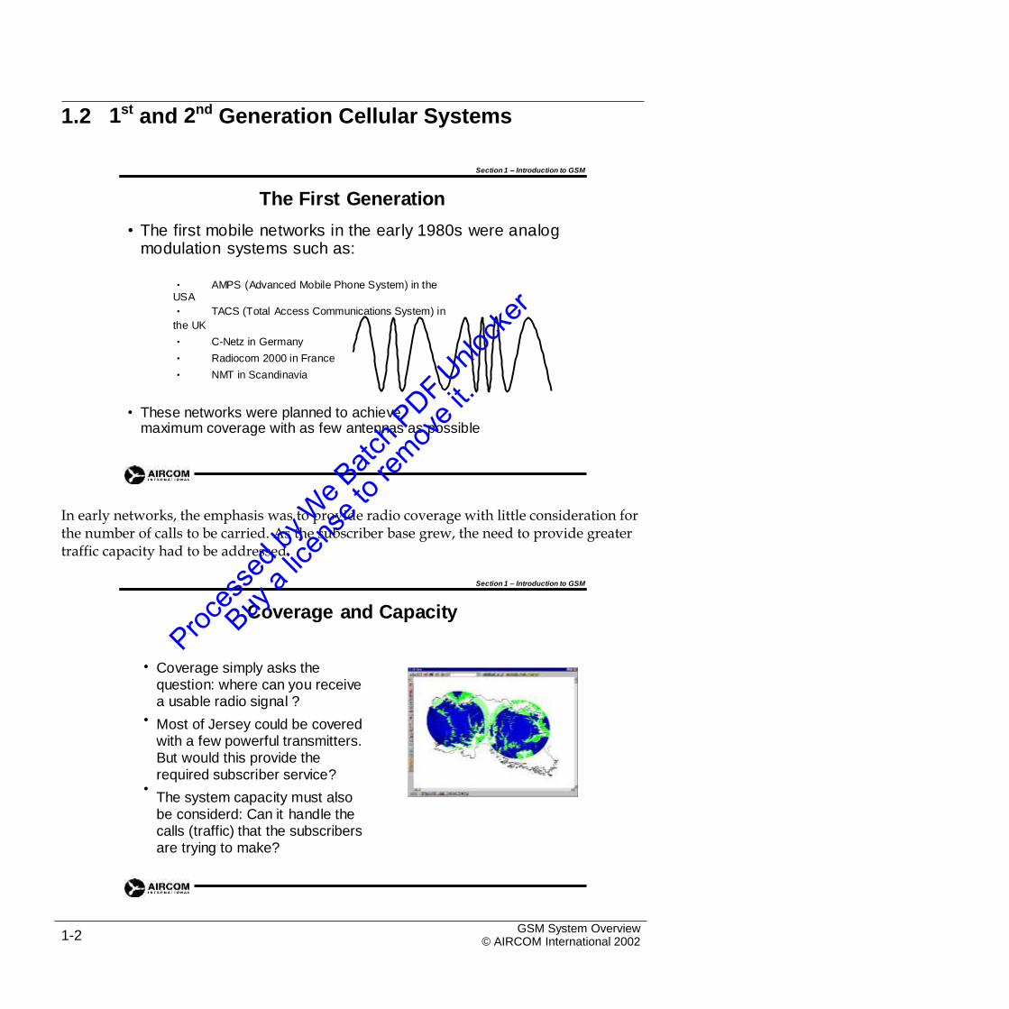
• Coverage simply asks the question: where can you receive a usable radio signal ?
Most of Jersey could be covered with a few powerful transmitters. But would this provide the required subscriber service?
The system capacity must also be considerd: Can it handle the calls (traffic) that the subscribers are trying to make?
•
•
GSM System Overview© AIRCOM International 20021-2
Section 1 – Introduction to GSM
The First Generation - Problems
• Problems with the analog systems included:
• Limited capacity – could not cope with increase in subscribers
• Bulky equipment
• Poor reliability
• Lack of security – analog signals could be intercepted
• Incompatibility between systems in different countries - no
roaming
• To improve on the analog systems, the European Conference of Postsand Telecommunications Administrations (CEPT) establishedGroupe Speciale Mobile (GSM) to set a new standard
Originally GSM referred to the European working party set up to establish anew standard. A digital system offered considerable advantages in terms of capacity and security and introduced new possibilities for data traffic.
Section 1 – Introduction to GSM
Second Generation - Digital
• 1987: GSM agreed on a digital standard
• The advantages of a digital system were:
• Efficient use of radio spectrum
• Security for voice transmission
• Possibilities of data transmission
• Very Large Scale Integrated (VLSI) components allowing smaller, cheaper handsets
• Compatibility with ISDN land based networks
• The system developed became the Global System forMobile
Telecommunications (also GSM)
GSM System Overview© AIRCOM International 2002 1-3
While first generation systems used a cellular structure and frequency re-usepatterns, digital systems developed this concept to include multi-layer cellular
patterns (microcells and macrocells). The greater immunity to interference inherent in digital transmission allowed tighter frequency re-use patterns to be implemented.
Section 1 – Introduction to GSM
GSM Cellular Structure
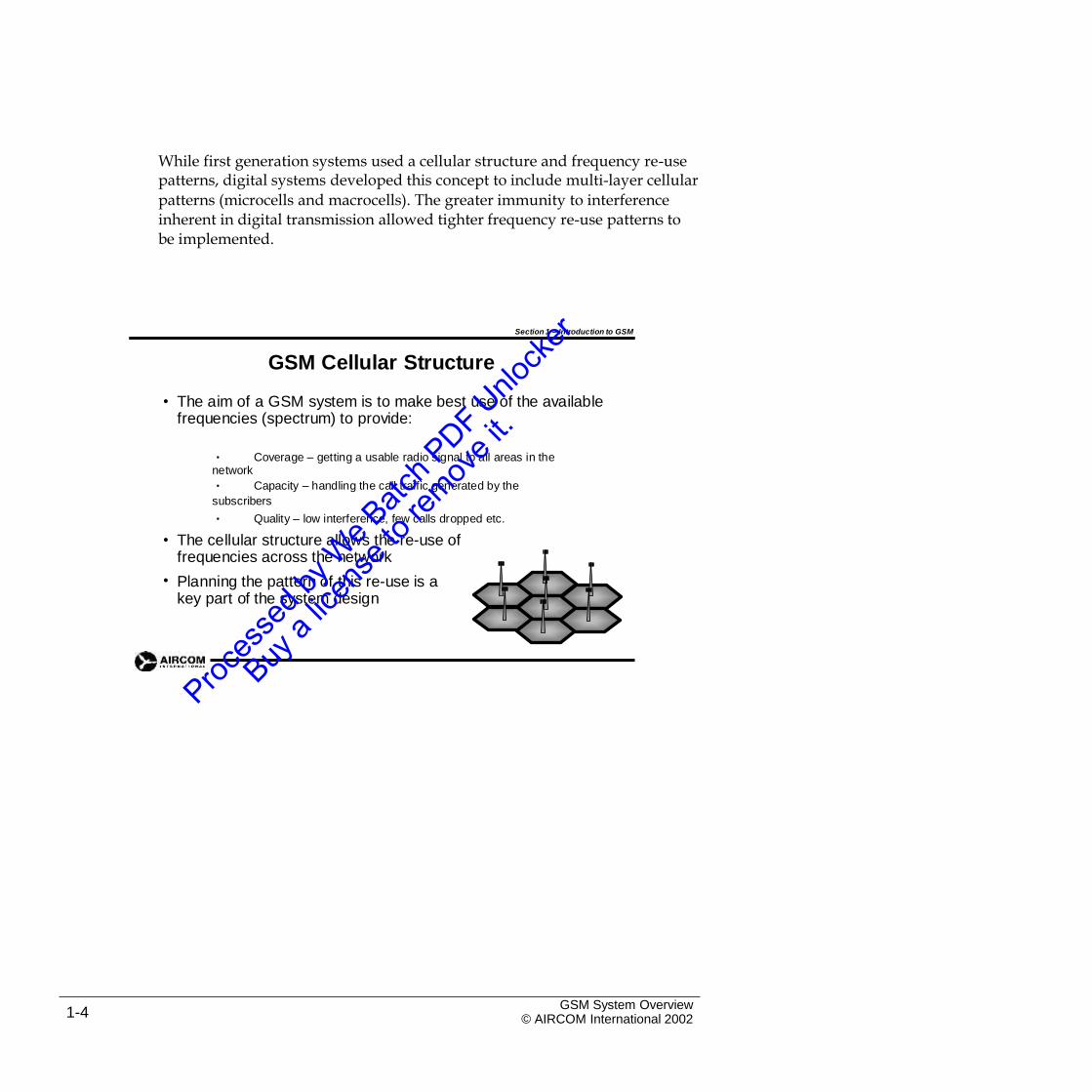
• The aim of a GSM system is to make best use of the available frequencies (spectrum) to provide:
• Coverage – getting a usable radio signal to all areas in thenetwork
• Capacity – handling the call traffic generated by the
subscribers
• Quality – low interference, few calls dropped etc.
• The cellular structure allows the re-use of frequencies across the network
Planning the pattern of this re-use is a key part of the system design
•
GSM System Overview© AIRCOM International 20021-4
1.3 GSM Architecture Overview
Section 1 – Introduction to GSM
GSM Architecture Overview
Air Interface(Um)
Abis Interface A Interface OMC
MS
HLRBSS
VLR
TRXMS
MSCBTS BSC
AuC
MS
EIR
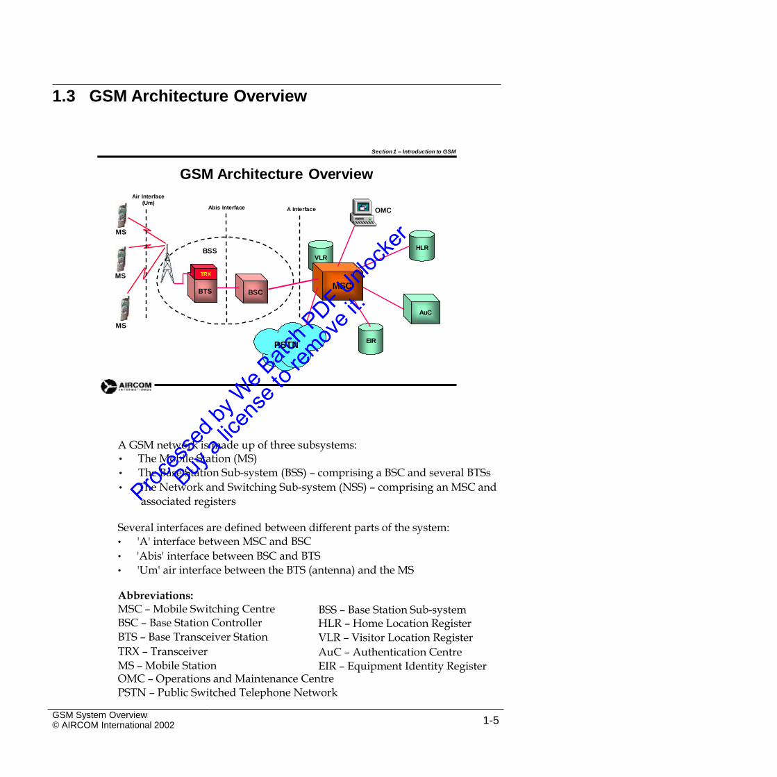
A GSM network is made up of three subsystems:• The Mobile Station (MS)
• The Base Station Sub-system (BSS) – comprising a BSC and several BTSs
• The Network and Switching Sub-system (NSS) – comprising an MSC and
associated registers
Several interfaces are defined between different parts of the system:• 'A' interface between MSC and BSC
• 'Abis' interface between BSC and BTS
• 'Um' air interface between the BTS (antenna) and the MS
Abbreviations:MSC – Mobile Switching CentreBSC – Base Station Controller
BTS – Base Transceiver Station
TRX – Transceiver
MS – Mobile Station
BSS – Base Station Sub-systemHLR – Home Location Register
VLR – Visitor Location Register
AuC – Authentication Centre
EIR – Equipment Identity RegisterOMC – Operations and Maintenance CentrePSTN – Public Switched Telephone Network
GSM System Overview© AIRCOM International 2002 1-5
PSTN
1.4 The GSM Mobile Station (MS)
Section 1 – Introduction to GSM
The Mobile Station (MS)
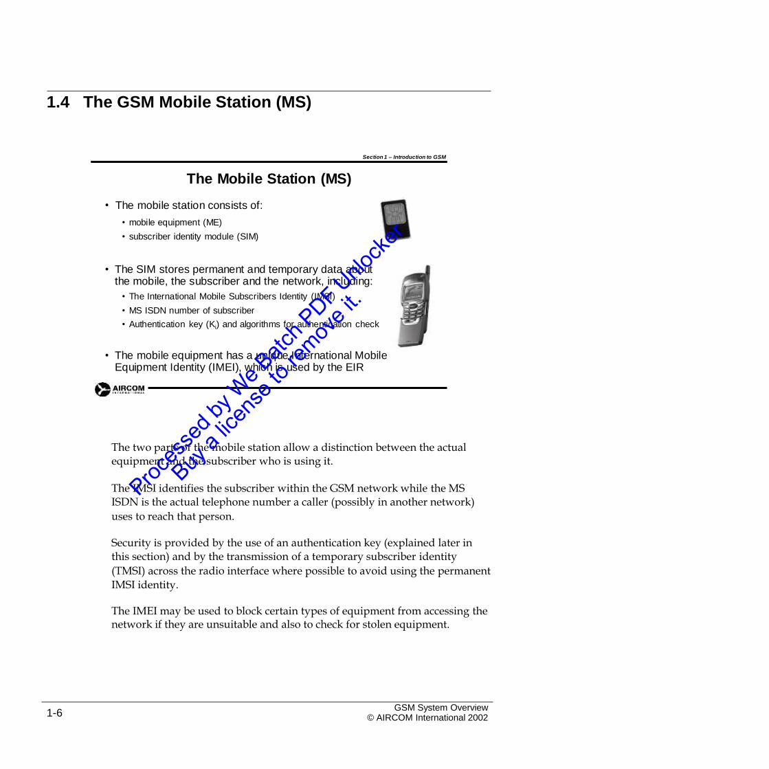
The mobile station consists of:
• mobile equipment (ME)
• subscriber identity module (SIM)
•
• The SIM stores permanent and temporary data about the mobile, the subscriber and the network, including:
• The International Mobile Subscribers Identity (IMSI)
• MS ISDN number of subscriber
• Authentication key (Ki) and algorithms for authentication check
• The mobile equipment has a unique International MobileEquipment Identity (IMEI), which is used by the EIR
The two parts of the mobile station allow a distinction between the actualequipment and the subscriber who is using it.
The IMSI identifies the subscriber within the GSM network while the MSISDN is the actual telephone number a caller (possibly in another network)
uses to reach that person.
Security is provided by the use of an authentication key (explained later inthis section) and by the transmission of a temporary subscriber identity
(TMSI) across the radio interface where possible to avoid using the permanent
IMSI identity.
The IMEI may be used to block certain types of equipment from accessing thenetwork if they are unsuitable and also to check for stolen equipment.
GSM System Overview© AIRCOM International 20021-6
1.5 The Base Station Subsystem (BSS)
Section 1 – Introduction to GSM
The Base Station Sub-System
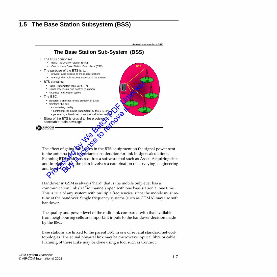
The BSS comprises:• Base Transcei ver Station (BTS)
• One or more Base Station Cont rollers (BSC)
The purpose of the BTS is to:• provide radio access to the mobile stations
• manage the radio access aspects of the system
BTS contains:
• Radi o Transmitter/Recei ver (TRX)
(BSS)
•
BSS
•
• BTS
• Signal processing and control equipment
• Antennas and feeder cables
The BSC:
• allocates a channel for the duration of a call
• maintains the call:
• monitori ng quality
• controlling the power transmitted by the BTS or MS
• generati ng a handover to another cell when required
Siting of the BTS is crucial to the provision of acceptable radio coverage
BSC
• BTS
BTS
BTS
•
The effect of gains and losses in the BTS equipment on the signal power sentto the antenna is an important consideration for link budget calculations.
Planning BTS positions requires a software tool such as Asset. Acquiring sitesand implementing the plan involves a combination of surveying, engineeringand legal work.
Handover in GSM is always ‘hard’ that is the mobile only ever has acommunication link (traffic channel) open with one base station at one time. This is true of any system with multiple frequencies, since the mobile must re-tune at the handover. Single frequency systems (such as CDMA) may use soft handover.
The quality and power level of the radio link compared with that availablefrom neighbouring cells are important inputs to the handover decision made
by the BSC.
Base stations are linked to the parent BSC in one of several standard networktopologies. The actual physical link may be microwave, optical fibre or cable.
Planning of these links may be done using a tool such as Connect.
GSM System Overview© AIRCOM International 2002 1-7
Section 1 – Introduction to GSM
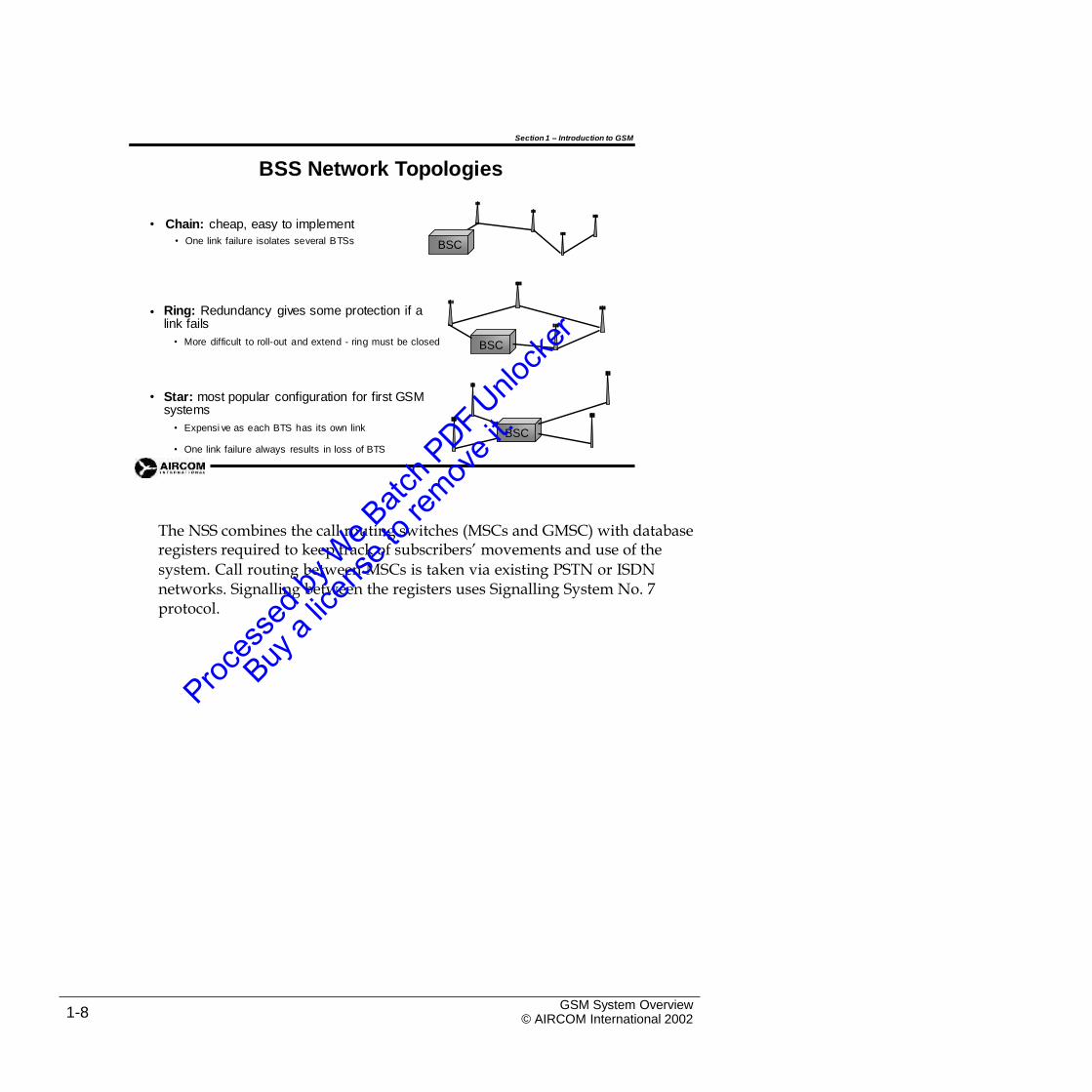
BSS Network Topologies
• Chain: cheap, easy to implement
• One link failure isolates several BTSs BSC
• Ring: Redundancy gives some protection if a link fails
• More difficult to roll-out and extend - ring must be closed BSC
• Star: most popular configuration for first GSMsystems
• Expensi ve as each BTS has its own linkBSC
• One link failure always results in loss of BTS
The NSS combines the call routing switches (MSCs and GMSC) with databaseregisters required to keep track of subscribers’ movements and use of the
system. Call routing between MSCs is taken via existing PSTN or ISDNnetworks. Signalling between the registers uses Signalling System No. 7protocol.
GSM System Overview© AIRCOM International 20021-8
1.6 The Network Switching System (NSS)
Section 1 – Introduction to GSM
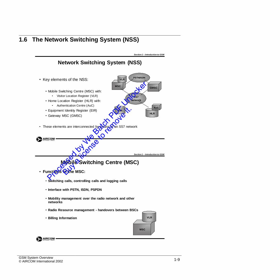
Network Switching System (NSS)
PSTN/ISDN• Key elements of the NSS: VLR
MSCGMSC
• Mobile Switching Centre (MSC) with:
• Visitor Location Register (VLR)
• Home Location Register (HLR) with:
• Authentication Centre (AuC)
• Equipment Identity Register (EIR)
• Gateway MSC (GMSC)
SS7
Network
AuCEIR
HLR
• These elements are interconnected by means of an SS7 network
Section 1 – Introduction to GSM
Mobile Switching Centre (MSC)
Functions of the MSC:•
• Switching calls, controlling calls and logging calls
• Interface with PSTN, ISDN, PSPDN
• Mobility management over the radio network and other networks
• Radio Resource management - handovers between BSCs
VLR• Billing Information
MSC
GSM System Overview© AIRCOM International 2002 1-9
Section 1 – Introduction to GSM
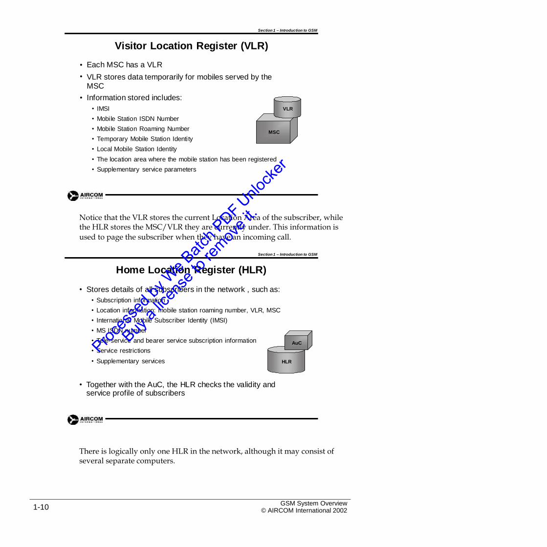
Visitor Location Register (VLR)
Each MSC has a VLR
VLR stores data temporarily for mobiles served by theMSC
Information stored includes:
•
•
•
• IMSI VLR
• Mobile Station ISDN Number
• Mobile Station Roaming Number
• Temporary Mobile Station Identity
• Local Mobile Station Identity
MSC
• The location area where the mobile station has been registered
• Supplementary service parameters
Notice that the VLR stores the current Location Area of the subscriber, whilethe HLR stores the MSC/VLR they are currently under. This information is
used to page the subscriber when they have an incoming call.
Section 1 – Introduction to GSM
Home Location Register (HLR)
• Stores details of all subscribers in the network , such as:
• Subscription information
• Location information: mobile station roaming number, VLR, MSC
• International Mobile Subscriber Identity (IMSI)
• MS ISDN number
• Tele-service and bearer service subscription information
• Service restrictions
AuC
• Supplementary services HLR
• Together with the AuC, the HLR checks the validity and service profile of subscribers
There is logically only one HLR in the network, although it may consist ofseveral separate computers.
GSM System Overview© AIRCOM International 20021-10
Section 1 – Introduction to GSM
HLR Implementation
• One HLR in a network
• May be split regionally
• Stores details of several thousand subscribers
• Stand alone computer - no switching capabilities
• May be located anywhere on the SS7 network
AuC• Combined with AuC
HLR
Section 1 – Introduction to GSM
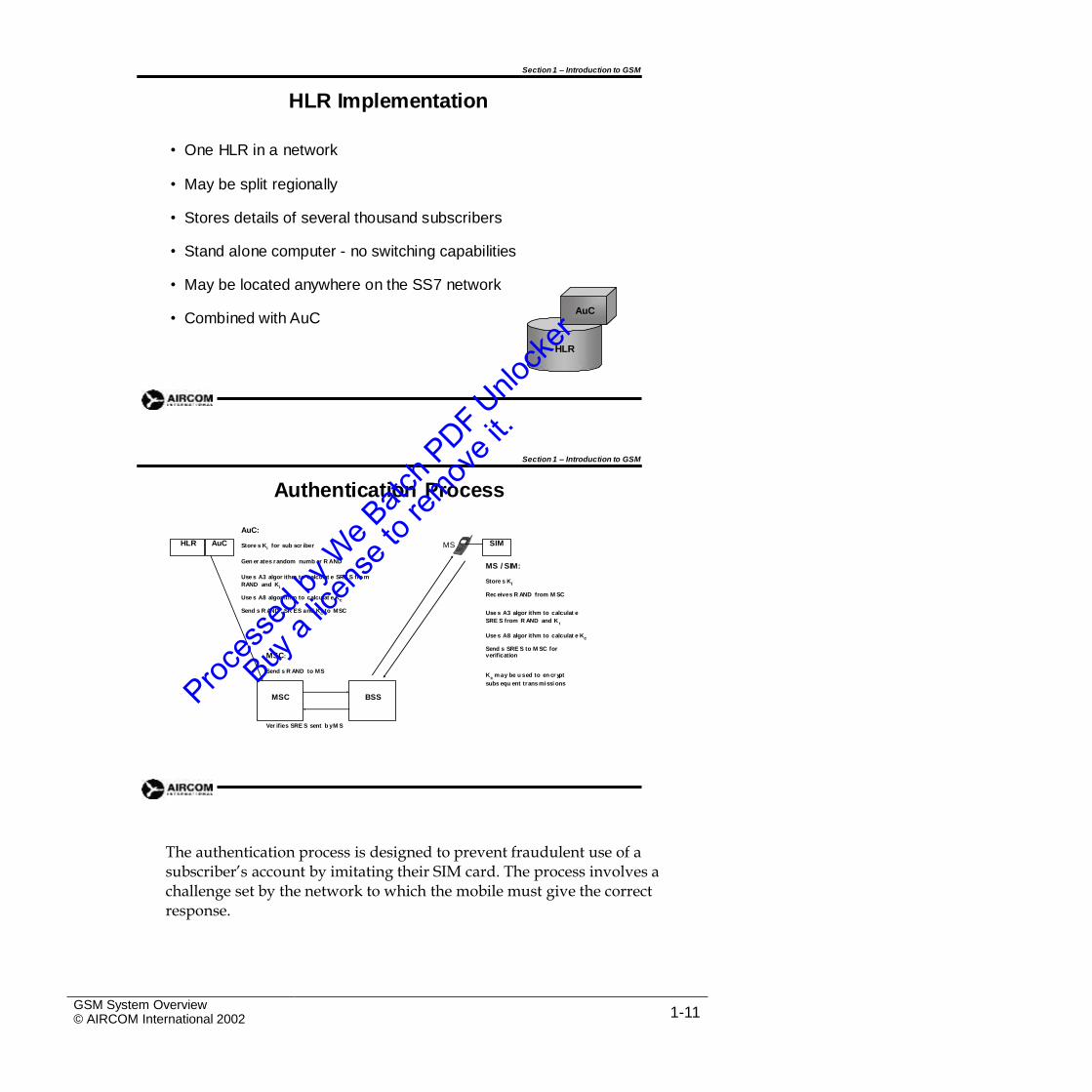
Authentication Process
AuC:
MSStore s Ki for sub scr iber
Gen er ates random numb er R ANDMS / SIM:
Use s A3 algor ithm to calculat e SRE S fro m
RAND and Ki
Use s A8 algor ithm to calculat e Kc
Send s R AND , SR ES and Kc to MSC
Store s KI
Rec eives R AND from M SC
Use s A3 algor ithm to calculat e
SRE S from R AND and Ki
Use s A8 algor ithm to calculat e Kc
Send s SRE S to M SC for verificationMSC:
Send s R AND to MSK m ay be u sed to en cr ypt
c
subs equ ent trans missi ons
Ver ifies SRE S sent b yM S
The authentication process is designed to prevent fraudulent use of asubscriber’s account by imitating their SIM card. The process involves a challenge set by the network to which the mobile must give the correct response.
GSM System Overview© AIRCOM International 2002 1-11
BSSMSC
SIMHLR AuC
There is a secret authentication key Ki for each subscriber, which is stored intheir SIM and in the AuC, but nowhere else.
The AuC generates a random number (RAND) which is passed together withthe key through an algorithm known as A3. This produces a signed result
value (SRES).
The values of RAND and SRES (but not the key) are passed to the MSC.
The MSC sends RAND to the mobile, which uses its key and the A3 algorithmto generate SRES.
The MS returns its SRES value to the MSC, which compares the two values. Ifthey are the same, the mobile is allowed on the network.
This system provides fairly good (but not perfect) protection against fraudand SIM cloning. It can however be broken.
The A8 algorithm is used to generate a second key (Kc) which is used to applyencryption to the voice or data being transmitted. Again this provides limited
protection against interception of the message.
Section 1 – Introduction to GSM
Equipment Identity Register (EIR)
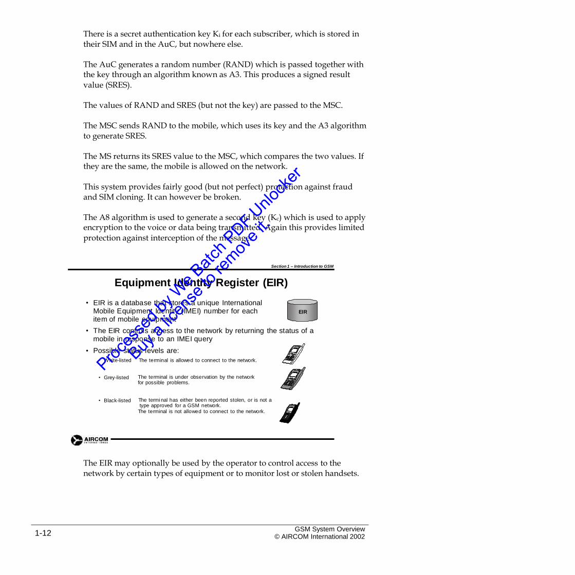
• EIR is a database that stores a unique International Mobile Equipment Identity (IMEI) number for each item of mobile equipment
EIR
• The EIR controls access to the network by returning the status of a mobile in response to an IMEI query
Possible status levels are:•
• White-listed The terminal is allowed to connect to the network.
• Grey-listed The terminal is under observation by the network for possible problems.
• Black-listed The termi nal has either been reported stolen, or is not a type approved for a GSM network.
The terminal is not allowed to connect to the network.
The EIR may optionally be used by the operator to control access to thenetwork by certain types of equipment or to monitor lost or stolen handsets.
GSM System Overview© AIRCOM International 20021-12
Section 1 – Introduction to GSM
Gateway Mobile Switching Centre (GMSC)
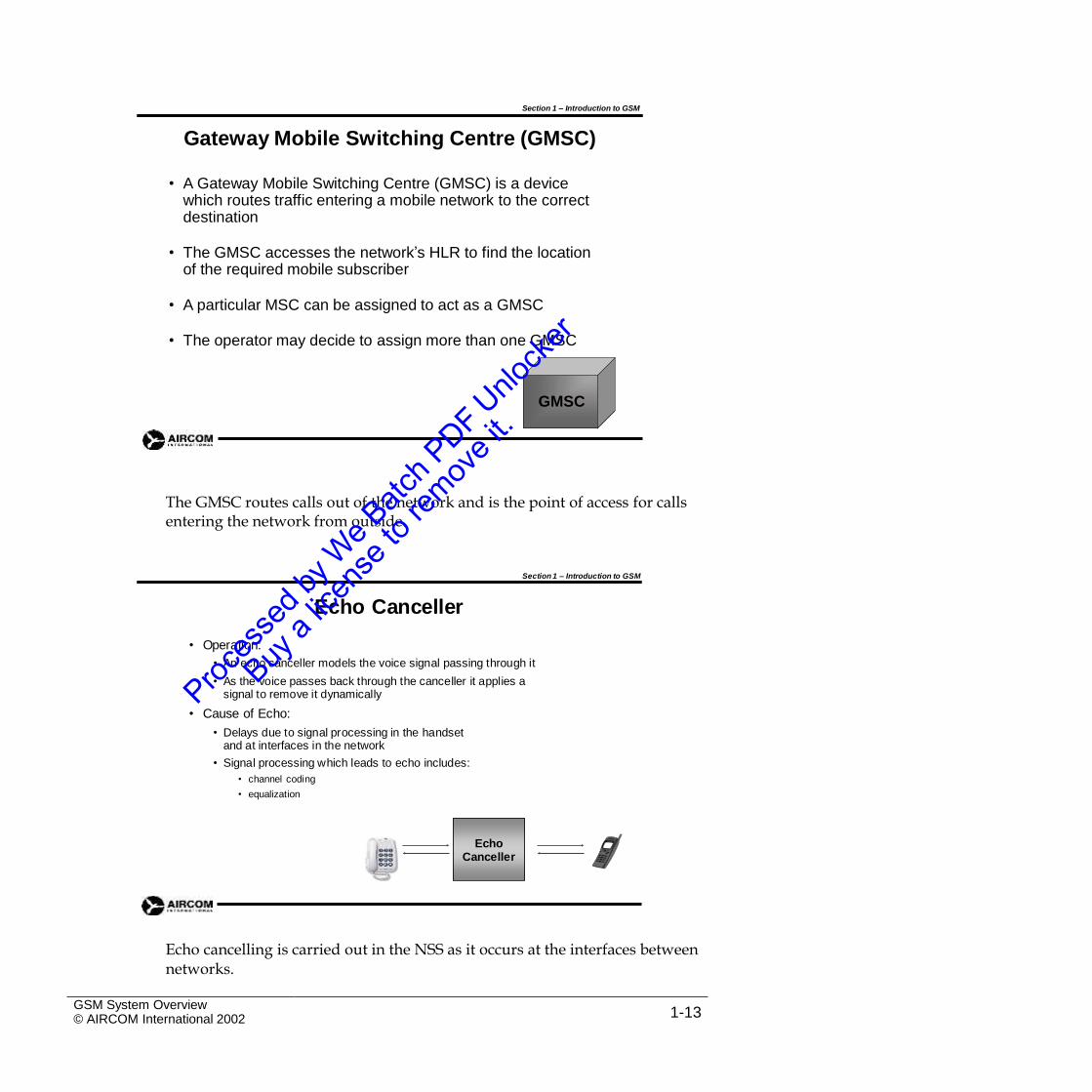
• A Gateway Mobile Switching Centre (GMSC) is a device which routes traffic entering a mobile network to the correct destination
• The GMSC accesses the network’s HLR to find the location of the required mobile subscriber
• A particular MSC can be assigned to act as a GMSC
• The operator may decide to assign more than one GMSC
GMSC
The GMSC routes calls out of the network and is the point of access for callsentering the network from outside.
Section 1 – Introduction to GSM
Echo Canceller
• Operation:
• An echo canceller models the voice signal passing through it
• As the voice passes back through the canceller it applies a signal to remove it dynamically
• Cause of Echo:
• Delays due to signal processing in the handset and at interfaces in the network
• Signal processing which leads to echo includes:
• channel coding
• equalization
Echo cancelling is carried out in the NSS as it occurs at the interfaces betweennetworks.
GSM System Overview© AIRCOM International 2002 1-13
EchoCanceller
Section 1 – Introduction to GSM
Billing
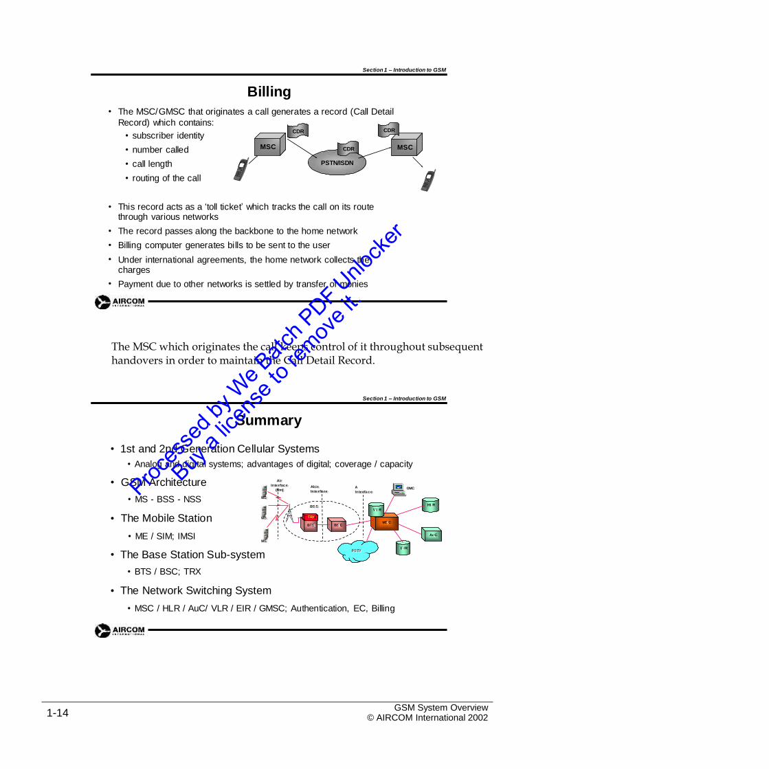
The MSC/GMSC that originates a call generates a record (Call Detail
Record) which contains:
•
CDRCDR• subscriber identity
• number called
• call length
• routing of the call
MSC MSCCDR
PSTN/ISDN
• This record acts as a ‘toll ticket’ which tracks the call on its route through various networks
The record passes along the backbone to the home network
Billing computer generates bills to be sent to the user
Under international agreements, the home network collects the charges
Payment due to other networks is settled by transfer of monies
•
•
•
•
The MSC which originates the call keeps control of it throughout subsequenthandovers in order to maintain the Call Detail Record.
Section 1 – Introduction to GSM
Summary
• 1st and 2nd Generation Cellular Systems
• Analog and digital systems; advantages of digital; coverage / capacity
• GSM Architecture
• MS - BSS - NSS
The Mobile Station
• ME / SIM; IMSI
AiirrIInntteerrffaaccee
((Um))AbbiissIInntteerrffaaccee
A
IInntteerrffaacceeOMC
MSS
HLLRBSSSSVVLLR
• TTRXX
BTTSS
MSSMSSC
BSSC
AuuC
MSS
EEIIR
• The Base Station Sub-system
• BTS / BSC; TRX
The Network Switching System
PSTNPSTN
•
• MSC / HLR / AuC/ VLR / EIR / GMSC; Authentication, EC, Billing
GSM System Overview© AIRCOM International 20021-14
Section 1 Self-Assessment Exercises
Exercise 1.1 – GSM Architecture
The following exercises tests your understanding of GSM architecture as applied to a smallnetwork.
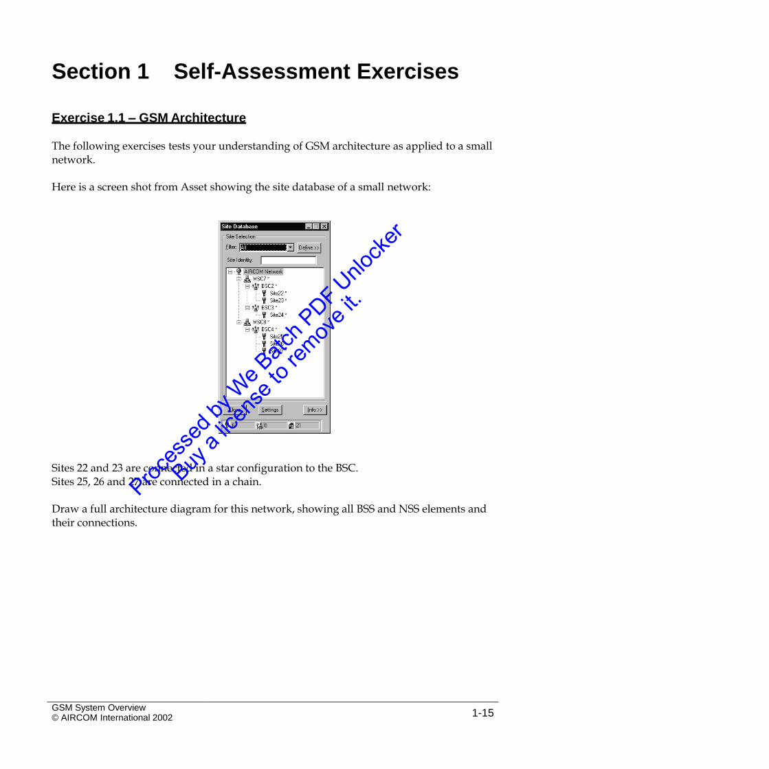
Here is a screen shot from Asset showing the site database of a small network:
Sites 22 and 23 are connected in a star configuration to the BSC.Sites 25, 26 and 27 are connected in a chain.
Draw a full architecture diagram for this network, showing all BSS and NSS elements andtheir connections.
GSM System Overview© AIRCOM International 2002 1-15

Intentional Blank Page
GSM System Overview© AIRCOM International 20021-16
2. Services and Operations
2.1 Introduction
This section covers some of the main services and operations within the GSMnetwork. Areas covered include:
•
•
•
•
Subscriber services offered by GSMNetwork areas
Roaming
Activities and operations in the network
GSM System Overview© AIRCOM International 2002 2-1
2.2 GSM Subscriber Services
Section 2 – Services & Operations
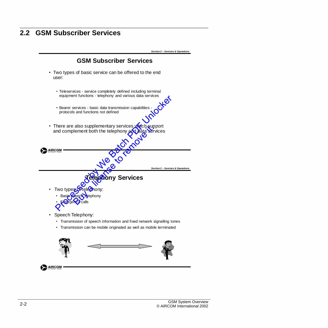
GSM Subscriber Services
• Two types of basic service can be offered to the end user:
• Teleservices - service completely defined including terminal equipment functions - telephony and various data services
• Bearer services - basic data transmission capabilities -protocols and functions not defined
• There are also supplementary services which support and complement both the telephony and data services
Section 2 – Services & Operations
Telephony Services
• Two types of telephony:
• Basic speech telephony
• Emergency calls
• Speech Telephony:
•
•
Transmission of speech information and fixed network signalling tones
Transmission can be mobile originated as well as mobile terminated
GSM System Overview© AIRCOM International 20022-2
Section 2 – Services & Operations
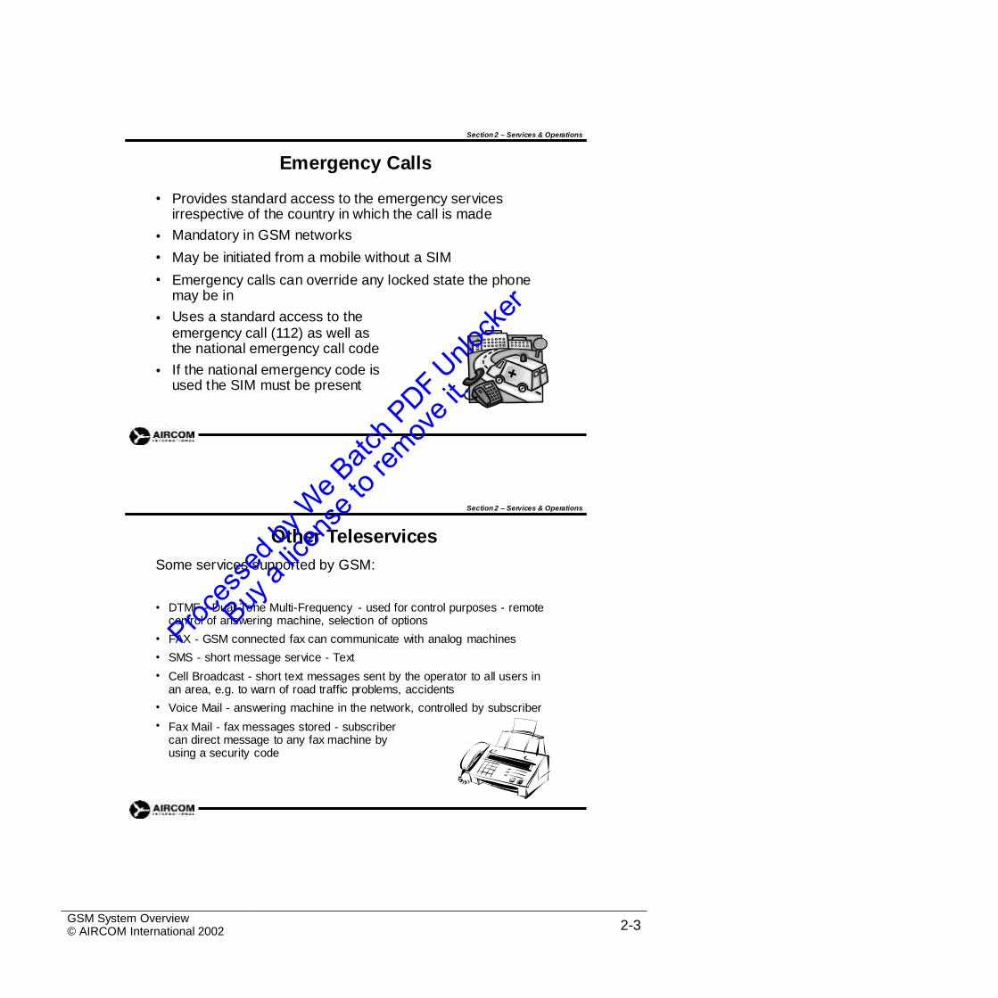
Emergency Calls
• Provides standard access to the emergency services irrespective of the country in which the call is made
Mandatory in GSM networks
May be initiated from a mobile without a SIM
Emergency calls can override any locked state the phone may be in
Uses a standard access to the
•
•
•
•emergency call (112) as well as the national emergency call code
If the national emergency code is used the SIM must be present
•
Section 2 – Services & Operations
Other Teleservices
Some services supported by GSM:
• DTMF - Dual Tone Multi-Frequency - used for control purposes - remote control of answering machine, selection of options
FAX - GSM connected fax can communicate with analog machines
SMS - short message service - Text
Cell Broadcast - short text messages sent by the operator to all users in an area, e.g. to warn of road traffic problems, accidents
Voice Mail - answering machine in the network, controlled by subscriber
Fax Mail - fax messages stored - subscriber can direct message to any fax machine by using a security code
•
•
•
•
•
GSM System Overview© AIRCOM International 2002 2-3
Section 2 – Services & Operations
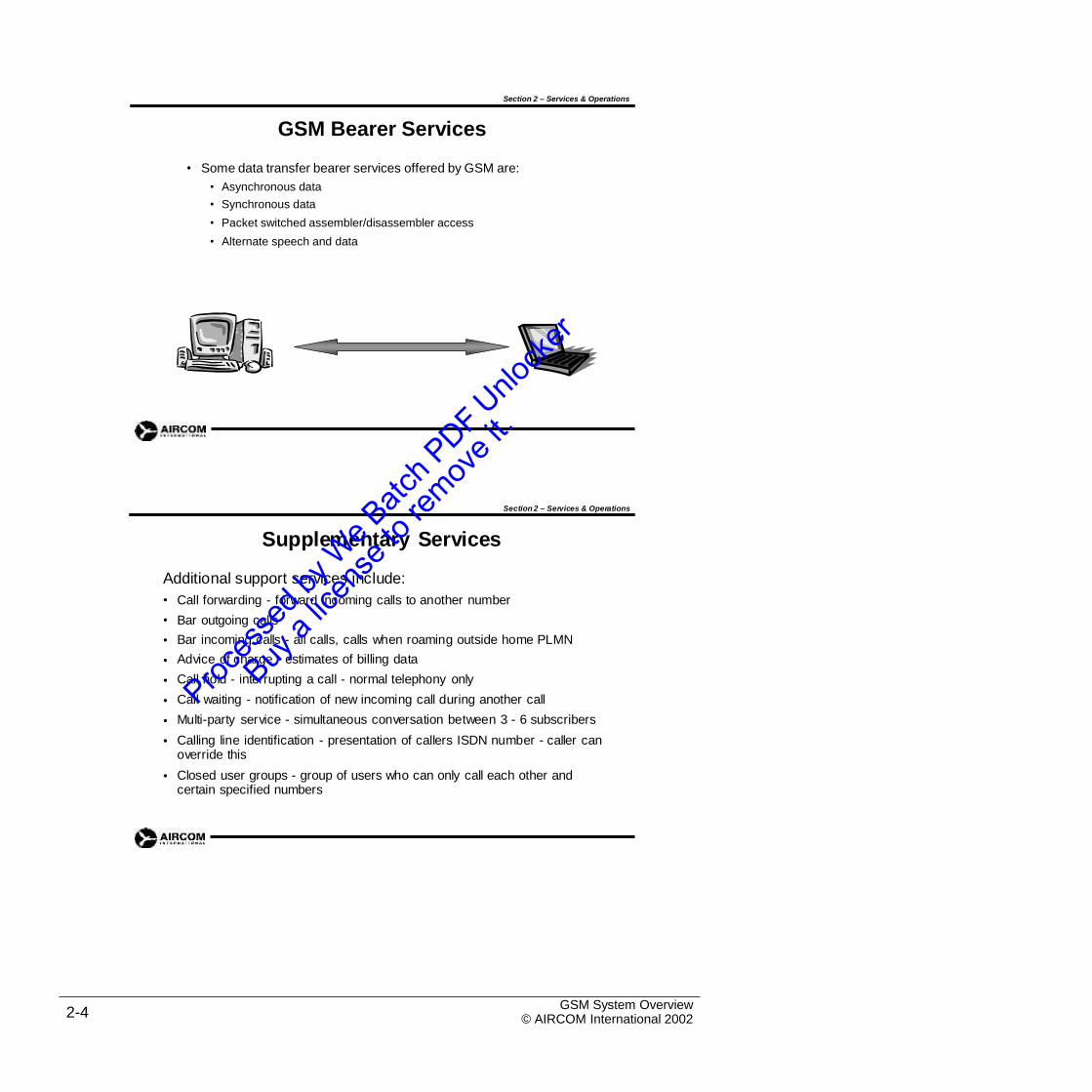
GSM Bearer Services
• Some data transfer bearer services offered by GSM are:
•
•
•
•
Asynchronous data
Synchronous data
Packet switched assembler/disassembler access
Alternate speech and data
Section 2 – Services & Operations
Supplementary Services
Additional support services include:
•
•
•
•
•
•
•
•
Call forwarding - forward incoming calls to another number
Bar outgoing calls
Bar incoming calls - all calls, calls when roaming outside home PLMN
Advice of charge - estimates of billing data
Call hold - interrupting a call - normal telephony only
Call waiting - notification of new incoming call during another call
Multi-party service - simultaneous conversation between 3 - 6 subscribers
Calling line identification - presentation of callers ISDN number - caller can override this
Closed user groups - group of users who can only call each other and certain specified numbers
•
GSM System Overview© AIRCOM International 20022-4
2.3 Network Areas
Section 2 – Services & Operations
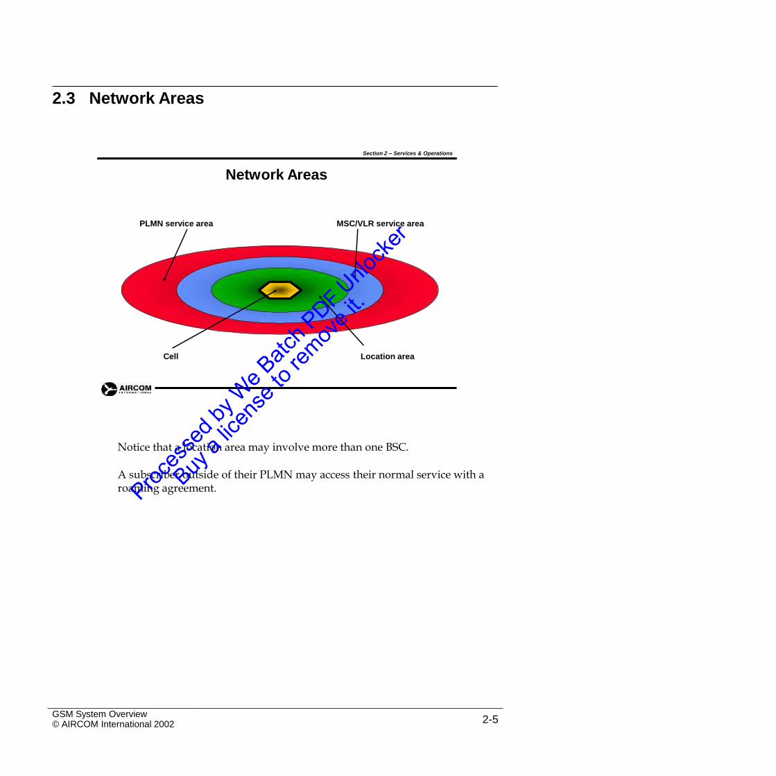
Network Areas
PLMN service area MSC/VLR service area
Cell Location area
Notice that a location area may involve more than one BSC.
A subscriber outside of their PLMN may access their normal service with aroaming agreement.
GSM System Overview© AIRCOM International 2002 2-5
2.4 Roaming
Section 2 – Services & Operations
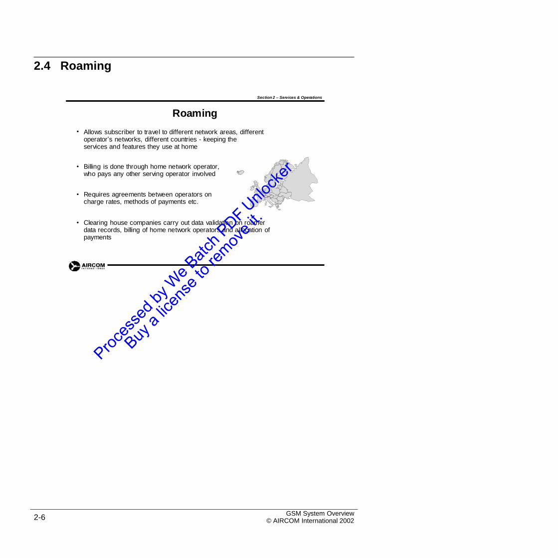
Roaming
Allows subscriber to travel to different network areas, different operator’s networks, different countries - keeping theservices and features they use at home
•
• Billing is done through home network operator, who pays any other serving operator involved
• Requires agreements between operators on charge rates, methods of payments etc.
• Clearing house companies carry out data validation on roamer data records, billing of home network operators and allocation of payments
GSM System Overview© AIRCOM International 20022-6
2.5 Activities and Operations
Section 2 – Services & Operations
Activities and Operations
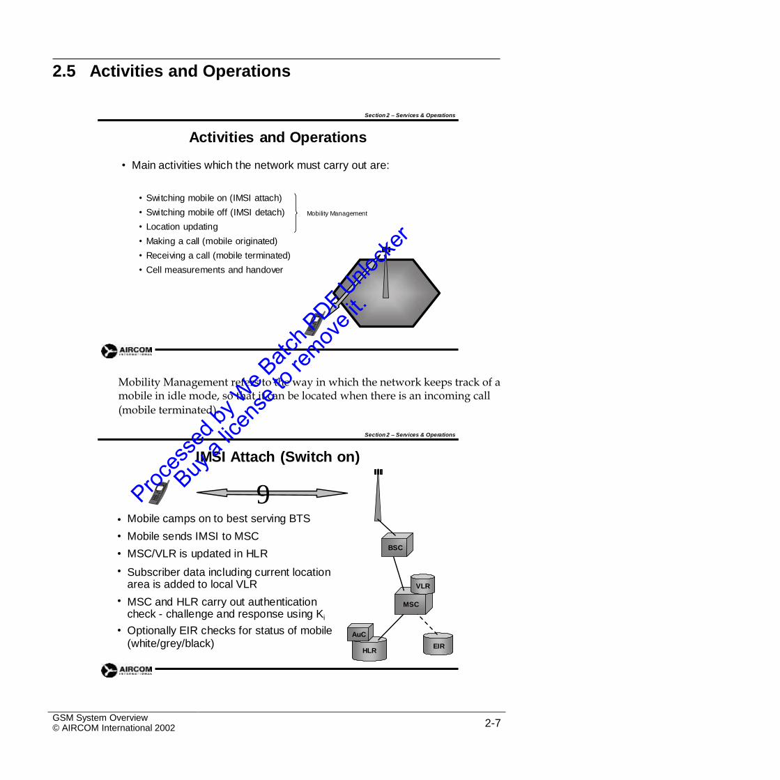
• Main activities which the network must carry out are:
• Switching mobile on (IMSI attach)
• Switching mobile off (IMSI detach)
• Location updating
• Making a call (mobile originated)
• Receiving a call (mobile terminated)
• Cell measurements and handover
Mobility Management
Mobility Management refers to the way in which the network keeps track of amobile in idle mode, so that it can be located when there is an incoming call
(mobile terminated).
Section 2 – Services & Operations
IMSI Attach (Switch on)
9Mobile camps on to best serving BTS
Mobile sends IMSI to MSC
MSC/VLR is updated in HLR
Subscriber data including current location area is added to local VLR
MSC and HLR carry out authentication check - challenge and response using Ki
Optionally EIR checks for status of mobile(white/grey/black)
•
•
•
•
BSC
VLR
• MSC
• AuC
EIRHLR
GSM System Overview© AIRCOM International 2002 2-7
The process of camping on to the best BTS is cell selection which involvescalculating a parameter C1 for each cell. Subsequent re-selections are based on a second parameter, C2. This is covered in detail in course G103.
Section 2 – Services & Operations
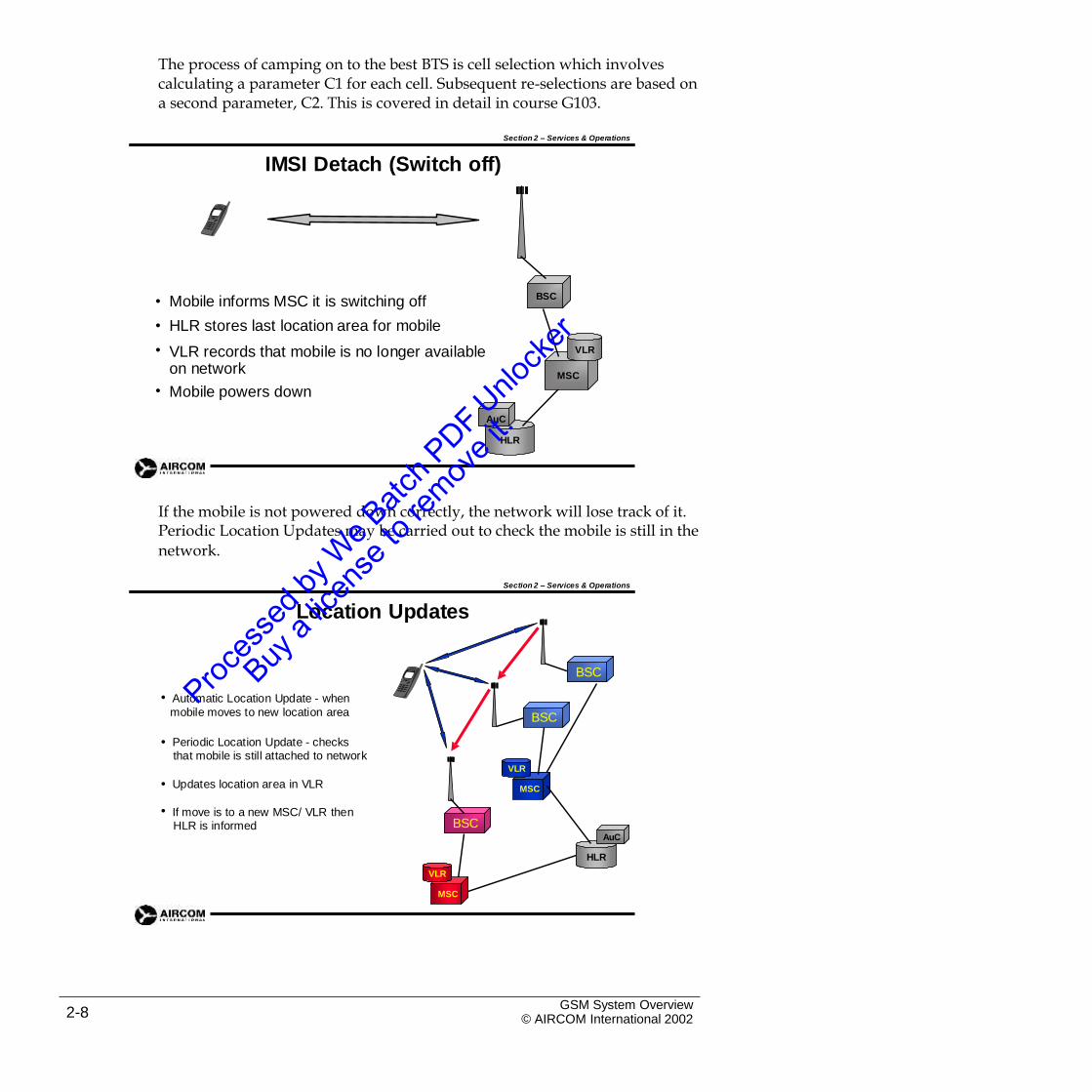
IMSI Detach (Switch off)
BSC•
•
•
Mobile informs MSC it is switching off
HLR stores last location area for mobile
VLR records that mobile is no longer available on network
Mobile powers down
AuC
VLR
MSC
•
HLR
If the mobile is not powered down correctly, the network will lose track of it.Periodic Location Updates may be carried out to check the mobile is still in the
network.
Section 2 – Services & Operations
Location Updates
BSC
• Automatic Location Update - when
mobile moves to new location area BSC
• Periodic Location Update - checksthat mobile is still attached to network
VLR
•
•
Updates location area in VLR MSC
If move is to a new MSC/ VLR thenHLR is informed BSC
AuC
HLR
VLR
MSC
GSM System Overview© AIRCOM International 20022-8
Section 2 – Services & Operations
Mobile Originated Call
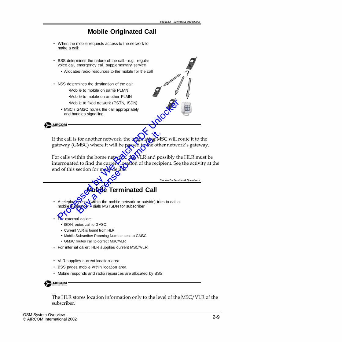
• When the mobile requests access to the network to make a call:
• BSS determines the nature of the call - e.g. regular voice call, emergency call, supplementary service
• Allocates radio resources to the mobile for the call ?• NSS determines the destination of the call:
•Mobile to mobile on same PLMN
•Mobile to mobile on another PLMN
•Mobile to fixed network (PSTN, ISDN)
• MSC / GMSC routes the call appropriately and handles signalling
If the call is for another network, the originating MSC will route it to thegateway (GMSC) where it will be passed to the other network’s gateway.
For calls within the home network, the VLR and possibly the HLR must beinterrogated to find the current location of the recipient. See the activity at the end of this section for more details.
Section 2 – Services & Operations
Mobile Terminated Call
• A telephone user (within the mobile network or outside) tries to call a mobile subscriber - dials MS ISDN for subscriber
• For external caller:
• ISDN routes call to GMSC
• Current VLR is found from HLR
• Mobile Subscriber Roaming Number sent to GMSC
• GMSC routes call to correct MSC/VLR
For internal caller: HLR supplies current MSC/VLR•
•
•
•
VLR supplies current location area
BSS pages mobile within location area
Mobile responds and radio resources are allocated by BSS
The HLR stores location information only to the level of the MSC/VLR of thesubscriber.
GSM System Overview© AIRCOM International 2002 2-9
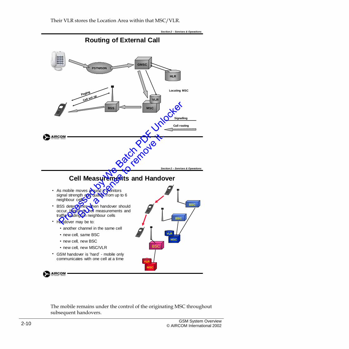
Their VLR stores the Location Area within that MSC/VLR.
Section 2 – Services & Operations
Routing of External Call
GMSCPSTN/ISDN
HLR
Locating MSC
VLR
BSS MSC
Signalling
Call routing
Section 2 – Services & Operations
Cell Measurements and Handover
• As mobile moves around it monitors signal strength and quality from up to 6 neighbour cells
BSS deter mines when handover shouldoccur, based on cell measurements andtraffic loading on neighbour cells
Handover may be to:
• another channel in the same cell
• new cell, same BSC
• new cell, new BSC
• new cell, new MSC/VLR
GSM handover is ‘hard’ - mobile only communicates with one cell at a time
BSC•
BSC•
VLR
MSC
BSC
•
VLR
MSC
The mobile remains under the control of the originating MSC throughoutsubsequent handovers.
GSM System Overview© AIRCOM International 20022-10
Example of an Inter – MSC handover:
The call starts with MSC A and is handed over to MSC B. As the call continuesit is necessary to handover to MSC C.
To do this, the call is first handed back to MSC A, which then hands it over toMSC C.
Intra-cell handovers (within the same cell) may occur if there is interferenceon a particular physical channel.
Section 2 – Services & Operations
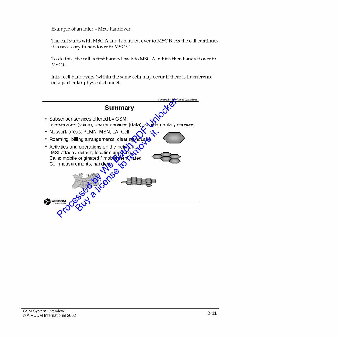
Summary
Subscriber services offered by GSM:tele-services (voice), bearer services (data), supplementary services
Network areas: PLMN, MSN, LA, Cell
Roaming: billing arrangements, clearing houses
Activities and operations on the network: IMSI attach / detach, location updating, Calls: mobile originated / mobile terminated Cell measurements, handover
•
•
•
•
GSM System Overview© AIRCOM International 2002 2-11

Intentional Blank Page
GSM System Overview© AIRCOM International 20022-12
Section 2 Self-Assessment Exercises
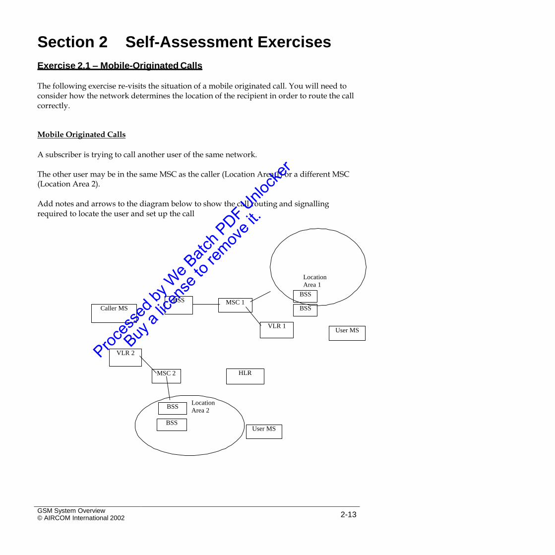
Exercise 2.1 – Mobile-Originated Calls
The following exercise re-visits the situation of a mobile originated call. You will need toconsider how the network determines the location of the recipient in order to route the call correctly.
Mobile Originated Calls
A subscriber is trying to call another user of the same network.
The other user may be in the same MSC as the caller (Location Area 1) or a different MSC(Location Area 2).
Add notes and arrows to the diagram below to show the call routing and signallingrequired to locate the user and set up the call
Location
Area 1
Location
Area 2
GSM System Overview© AIRCOM International 2002 2-13
User MSBSS
BSS
HLRMSC 2
VLR 2
User MSVLR 1
Caller MS
BSS MSC 1
BSS
BSS
Intentional Blank Page
GSM System Overview© AIRCOM International 20022-14
3. Radio Waves and Antennas
3.1 Introduction
This section looks briefly at the basic physics of electromagnetic waves toprepare for considering the effects of the environment on the propagation of radio waves later in the course.
GSM System Overview© AIRCOM International 2002 3-1
3.2 Radio Wave Propagation
Section 3 – Radio Waves & Antennas
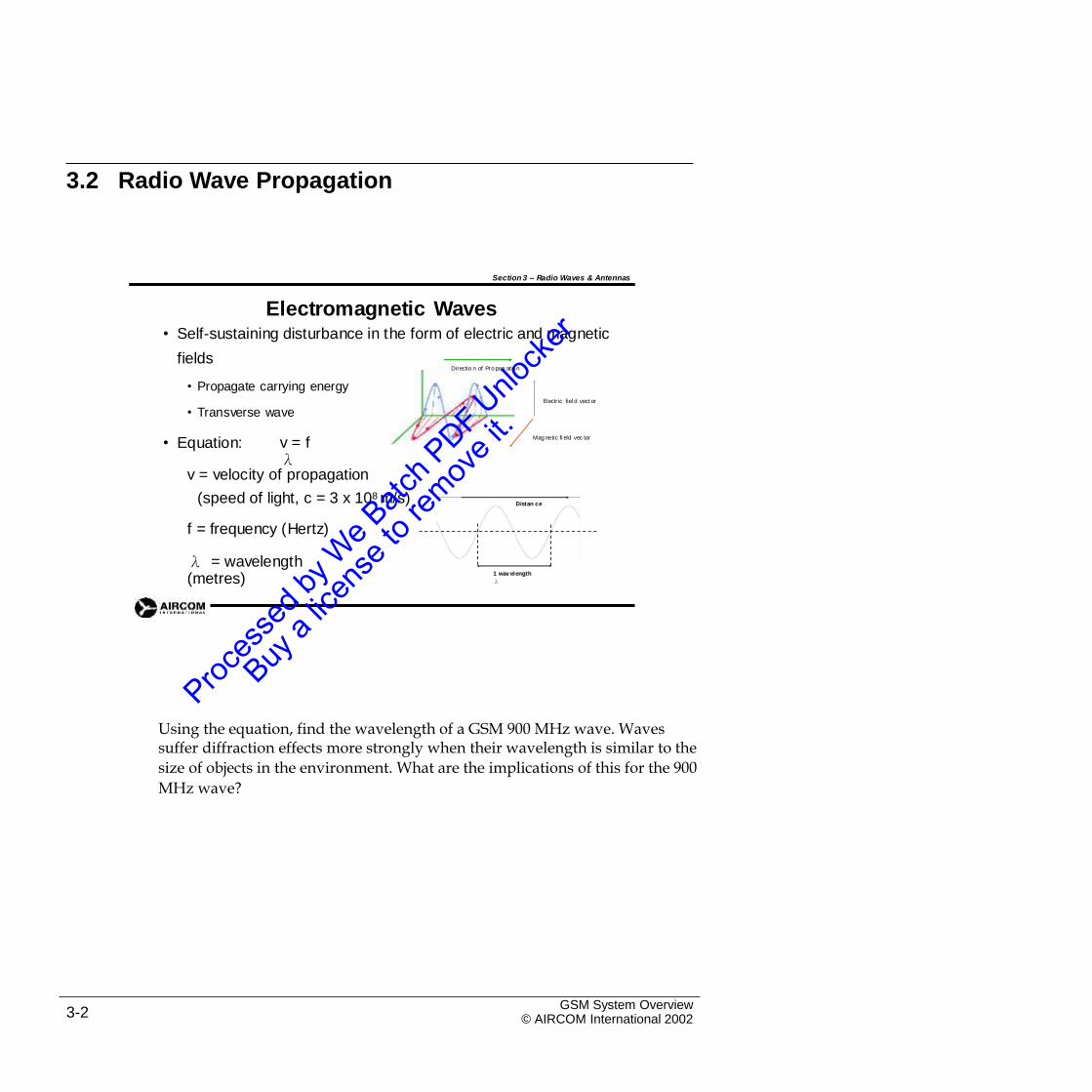
Electromagnetic WavesSelf-sustaining disturbance in the form of electric and magnetic
fields
• Propagate carrying energy
•
Directio n of Pro pag ation
Electric fiel d vect or
• Transverse wave
• Equation: v = fλ
Mag netic fi eld vec tor
v = velocity of propagation
(speed of light, c = 3 x 10⁸ m/s)
f = frequency (Hertz)
Distan ce
λ = wavelength(metres)
1 wav elength
λ
Using the equation, find the wavelength of a GSM 900 MHz wave. Wavessuffer diffraction effects more strongly when their wavelength is similar to the
size of objects in the environment. What are the implications of this for the 900
MHz wave?
GSM System Overview© AIRCOM International 20023-2
Section 3 – Radio Waves & Antennas
Polarization
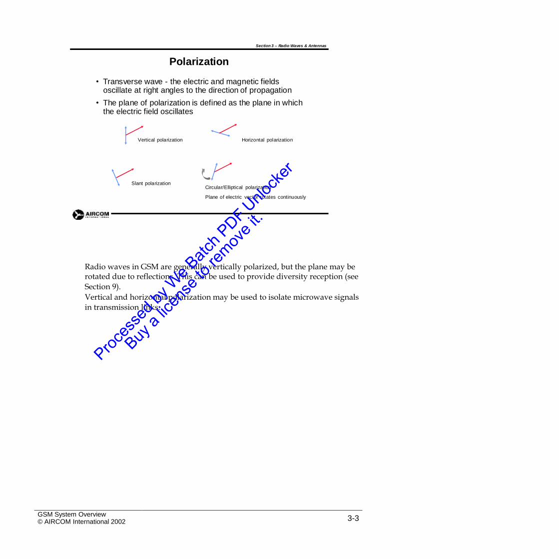
• Transverse wave - the electric and magnetic fields oscillate at right angles to the direction of propagation
• The plane of polarization is defined as the plane in which the electric field oscillates
Vertical polarization Horizontal polarization
Slant polarizationCircular/Elliptical polarization
Plane of electric vector rotates continuously
Radio waves in GSM are generally vertically polarized, but the plane may berotated due to reflections. This can be used to provide diversity reception (see
Section 9).
Vertical and horizontal polarization may be used to isolate microwave signals
in transmission links.
GSM System Overview© AIRCOM International 2002 3-3
3.3 Radio Spectrum
Section 3 – Radio Waves & Antennas
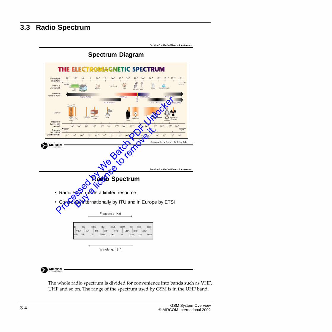
Spectrum Diagram
Advanced Light Source, Berkeley Lab.
Section 3 – Radio Waves & Antennas
Radio Spectrum
• Radio Spectrum is a limited resource
• Controlled internationally by ITU and in Europe by ETSI
Frequency (Hz)
Wavelength (m)
The whole radio spectrum is divided for convenience into bands such as VHF,UHF and so on. The range of the spectrum used by GSM is in the UHF band.
GSM System Overview© AIRCOM International 20023-4
Section 3 – Radio Waves & Antennas
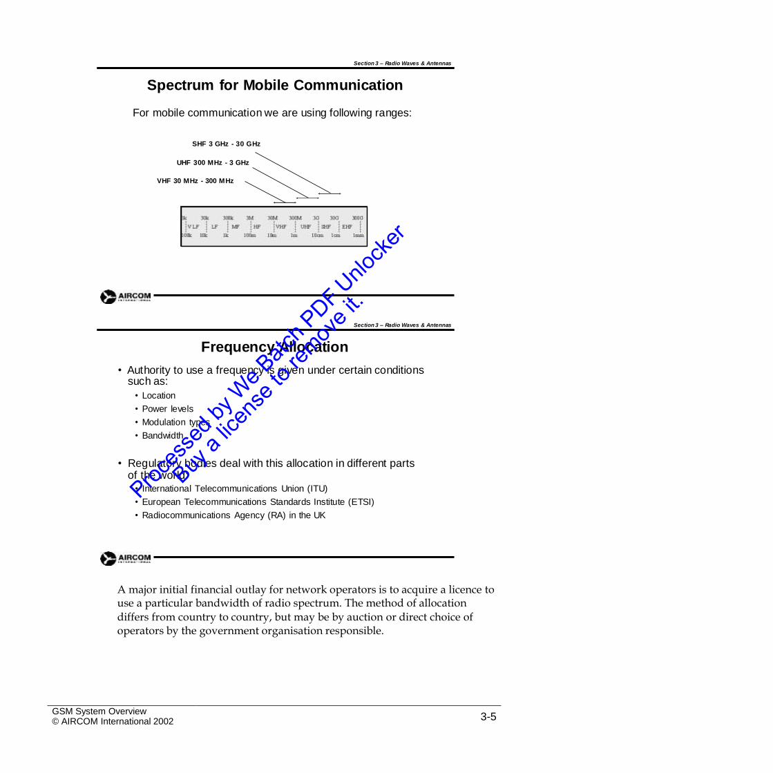
Spectrum for Mobile Communication
For mobile communication we are using following ranges:
SHF 3 GHz - 30 GHz
UHF 300 MHz - 3 GHz
VHF 30 MHz - 300 MHz
Section 3 – Radio Waves & Antennas
Frequency Allocation
• Authority to use a frequency is given under certain conditions such as:
• Location
• Power levels
• Modulation types
• Bandwidth
• Regulatory bodies deal with this allocation in different parts of the world:
• International Telecommunications Union (ITU)
• European Telecommunications Standards Institute (ETSI)
• Radiocommunications Agency (RA) in the UK
A major initial financial outlay for network operators is to acquire a licence touse a particular bandwidth of radio spectrum. The method of allocation
differs from country to country, but may be by auction or direct choice of operators by the government organisation responsible.
GSM System Overview© AIRCOM International 2002 3-5
3.4 GSM Spectrum Allocation
Section 3 – Radio Waves & Antennas
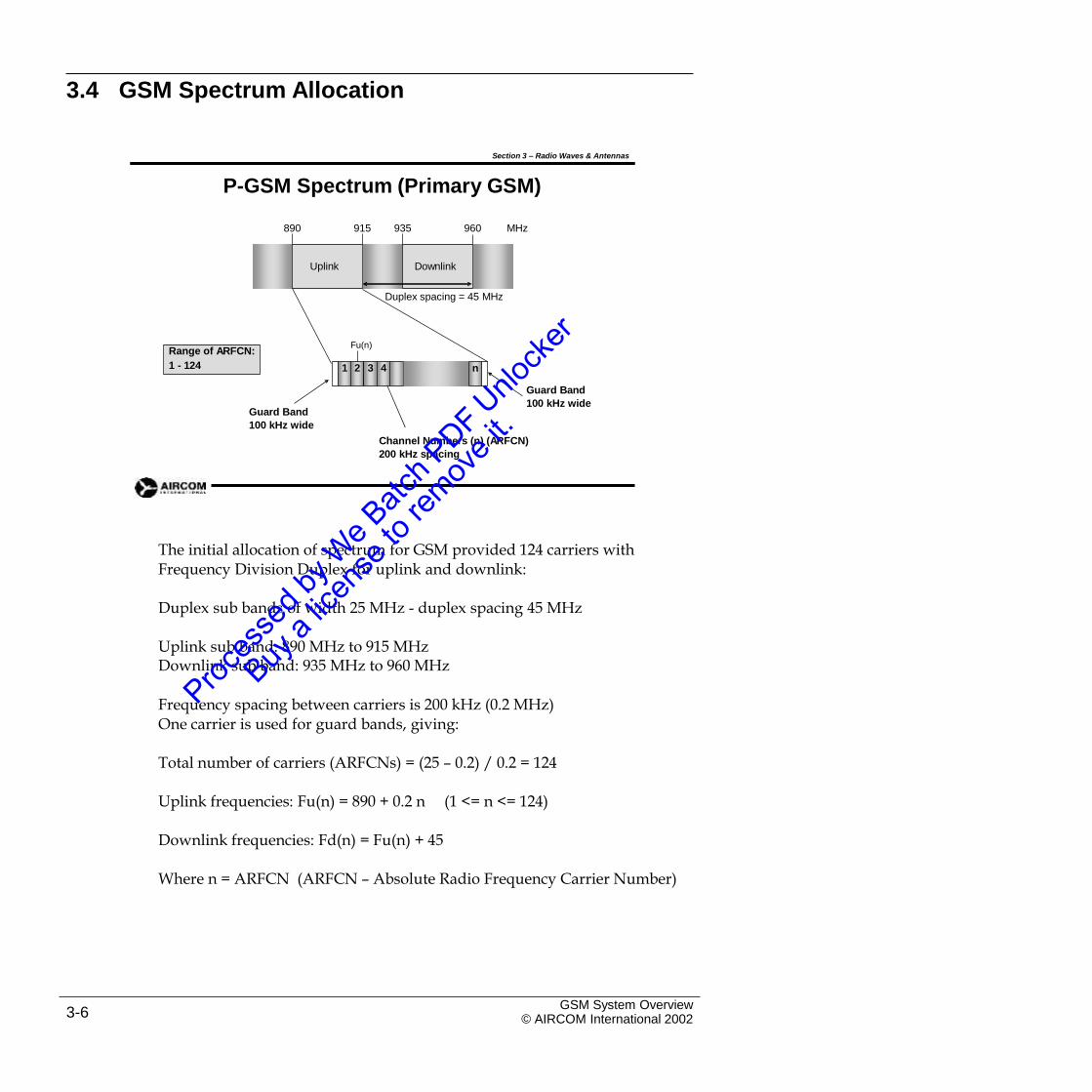
P-GSM Spectrum (Primary GSM)
890 915 935 960 MHz
Duplex spacing = 45 MHz
Fu(n)
Guard Band
100 kHz wideGuard Band
100 kHz wide
Channel Numbers (n) (ARFCN)
200 kHz spacing
The initial allocation of spectrum for GSM provided 124 carriers withFrequency Division Duplex for uplink and downlink:
Duplex sub bands of width 25 MHz - duplex spacing 45 MHz
Uplink sub band: 890 MHz to 915 MHzDownlink sub band: 935 MHz to 960 MHz
Frequency spacing between carriers is 200 kHz (0.2 MHz)One carrier is used for guard bands, giving:
Total number of carriers (ARFCNs) = (25 – 0.2) / 0.2 = 124
Uplink frequencies: Fu(n) = 890 + 0.2 n (1 <= n <= 124)
Downlink frequencies: Fd(n) = Fu(n) + 45
Where n = ARFCN (ARFCN – Absolute Radio Frequency Carrier Number)
GSM System Overview© AIRCOM International 20023-6
n1 2 3 4
Range of ARFCN:
1 - 124
DownlinkUplink
Section 3 – Radio Waves & Antennas
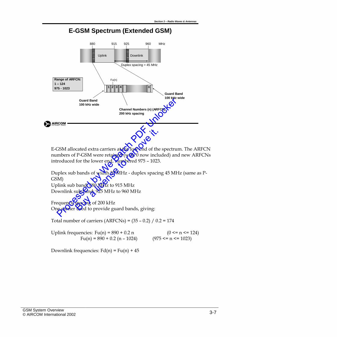
E-GSM Spectrum (Extended GSM)
880 915 925 960 MHz
Duplex spacing = 45 MHz
Fu(n)
Guard Band
100 kHz wideGuard Band
100 kHz wide
Channel Numbers (n) (ARFCN)
200 kHz spacing
E-GSM allocated extra carriers at the low end of the spectrum. The ARFCNnumbers of P-GSM were retained (with 0 now included) and new ARFCNs introduced for the lower end, numbered 975 – 1023.
Duplex sub bands of width 35 MHz - duplex spacing 45 MHz (same as P-GSM)
Uplink sub band: 880 MHz to 915 MHz
Downlink sub band: 925 MHz to 960 MHz
Frequency spacing of 200 kHzOne carrier used to provide guard bands, giving:
Total number of carriers (ARFCNs) = (35 – 0.2) / 0.2 = 174
Uplink frequencies: Fu(n) = 890 + 0.2 nFu(n) = 890 + 0.2 (n – 1024)
(0 <= n <= 124)(975 <= n <= 1023)
Downlink frequencies: Fd(n) = Fu(n) + 45
GSM System Overview© AIRCOM International 2002 3-7
n1 2 3 4
Range of ARFCN:
1 – 124
975 - 1023
DownlinkUplink
Section 3 – Radio Waves & Antennas
DCS-1800 Spectrum
1710 1785 1805 1880 MHz
Duplex spacing = 95 MHz
Fu(n)
Guard Band
100 kHz wideGuard Band
100 kHz wide
Channel Numbers (n) (ARFCN)
200 kHz spacing
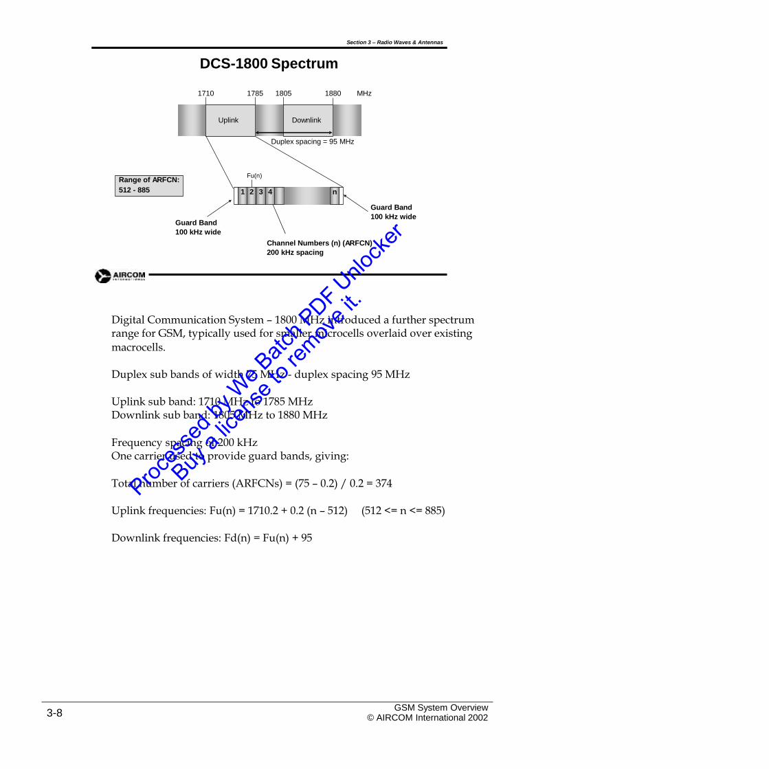
Digital Communication System – 1800 MHz introduced a further spectrumrange for GSM, typically used for smaller microcells overlaid over existing
macrocells.
Duplex sub bands of width 75 MHz - duplex spacing 95 MHz
Uplink sub band: 1710 MHz to 1785 MHzDownlink sub band: 1805 MHz to 1880 MHz
Frequency spacing of 200 kHzOne carrier used to provide guard bands, giving:
Total number of carriers (ARFCNs) = (75 – 0.2) / 0.2 = 374
Uplink frequencies: Fu(n) = 1710.2 + 0.2 (n – 512) (512 <= n <= 885)
Downlink frequencies: Fd(n) = Fu(n) + 95
GSM System Overview© AIRCOM International 20023-8
n1 2 3 4
Range of ARFCN:
512 - 885
DownlinkUplink
Section 3 – Radio Waves & Antennas
PCS-1900 Spectrum
1850 1910 1930 1990 MHz
Duplex spacing = 80 MHz
Fu(n)
Guard Band
100 kHz wideGuard Band
100 kHz wide
Channel Numbers (n) (ARFCN)
200 kHz spacing
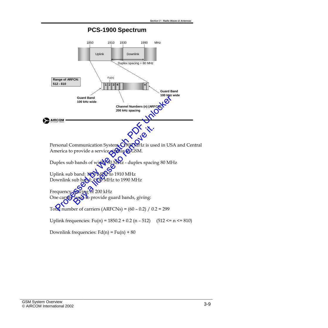
Personal Communication System – 1900 MHz is used in USA and CentralAmerica to provide a service similar to GSM.
Duplex sub bands of width 60 MHz - duplex spacing 80 MHz
Uplink sub band: 1850 MHz to 1910 MHzDownlink sub band: 1930 MHz to 1990 MHz
Frequency spacing of 200 kHzOne carrier used to provide guard bands, giving:
Total number of carriers (ARFCNs) = (60 – 0.2) / 0.2 = 299
Uplink frequencies: Fu(n) = 1850.2 + 0.2 (n – 512) (512 <= n <= 810)
Downlink frequencies: Fd(n) = Fu(n) + 80
GSM System Overview© AIRCOM International 2002 3-9
n1 2 3 4
Range of ARFCN:
512 - 810
DownlinkUplink
Section 3 – Radio Waves & Antennas
1800 MHz Utilization in UK
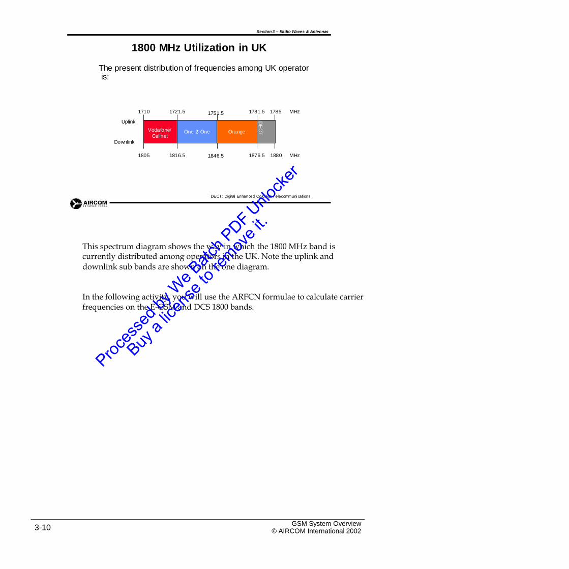
The present distribution of frequencies among UK operator is:
1710 1721.5 1781.5 1785 MHz1751.5
Uplink
Downlink
1805 1816.5 1876.5 1880 MHz1846.5
DECT: Digital Enhanced Cordless Telecommuni cations
This spectrum diagram shows the way in which the 1800 MHz band iscurrently distributed among operators in the UK. Note the uplink and
downlink sub bands are shown on the one diagram.
In the following activity, you will use the ARFCN formulae to calculate carrierfrequencies on the E-GSM and DCS 1800 bands.
GSM System Overview© AIRCOM International 20023-10
Vodafone/
CellnetOne 2 One Orange
DE
CT
TRXTRX
3.5 GSM Antenna Types
Section 3 – Radio Waves & Antennas
Antennas
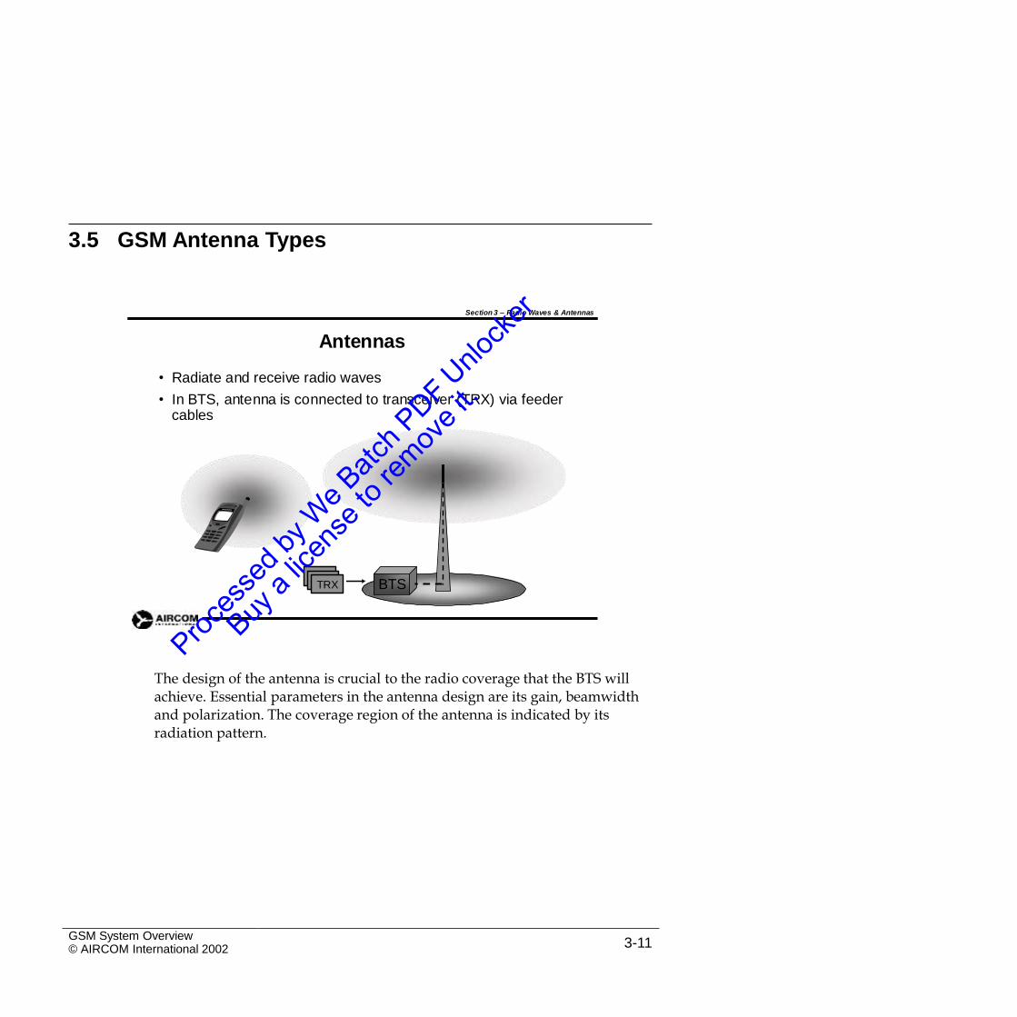
• Radiate and receive radio waves
• In BTS, antenna is connected to transceiver (TRX) via feeder cables
BTSTRX
The design of the antenna is crucial to the radio coverage that the BTS willachieve. Essential parameters in the antenna design are its gain, beamwidth and polarization. The coverage region of the antenna is indicated by its radiation pattern.
GSM System Overview© AIRCOM International 2002 3-11
Section 3 – Radio Waves & Antennas
Isotropic Radiator
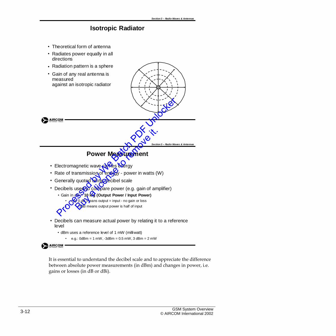
•
•
Theoretical form of antenna
Radiates power equally in all directions
Radiation pattern is a sphere
Gain of any real antenna is measuredagainst an isotropic radiator
•
•
Section 3 – Radio Waves & Antennas
Power Measurement
•
•
•
•
Electromagnetic wave carries energy
Rate of transmission of energy - power in watts (W)
Generally quoted using decibel scale
Decibels used to compare power (e.g. gain of amplifier)
• Gain in dB = 10 log (Output Power / Input Power)
• e.g. 0 dB means output = input - no gain or loss
• -3dB means output power is half of input
• Decibels can measure actual power by relating it to a reference level
• dBm uses a reference level of 1 mW (milliwatt)
• e.g.: 0dBm = 1 mW, -3dBm = 0.5 mW, 3 dBm = 2 mW
It is essential to understand the decibel scale and to appreciate the differencebetween absolute power measurements (in dBm) and changes in power, i.e. gains or losses (in dB or dBi).
GSM System Overview© AIRCOM International 20023-12
Section 3 – Radio Waves & Antennas
Antenna Gain
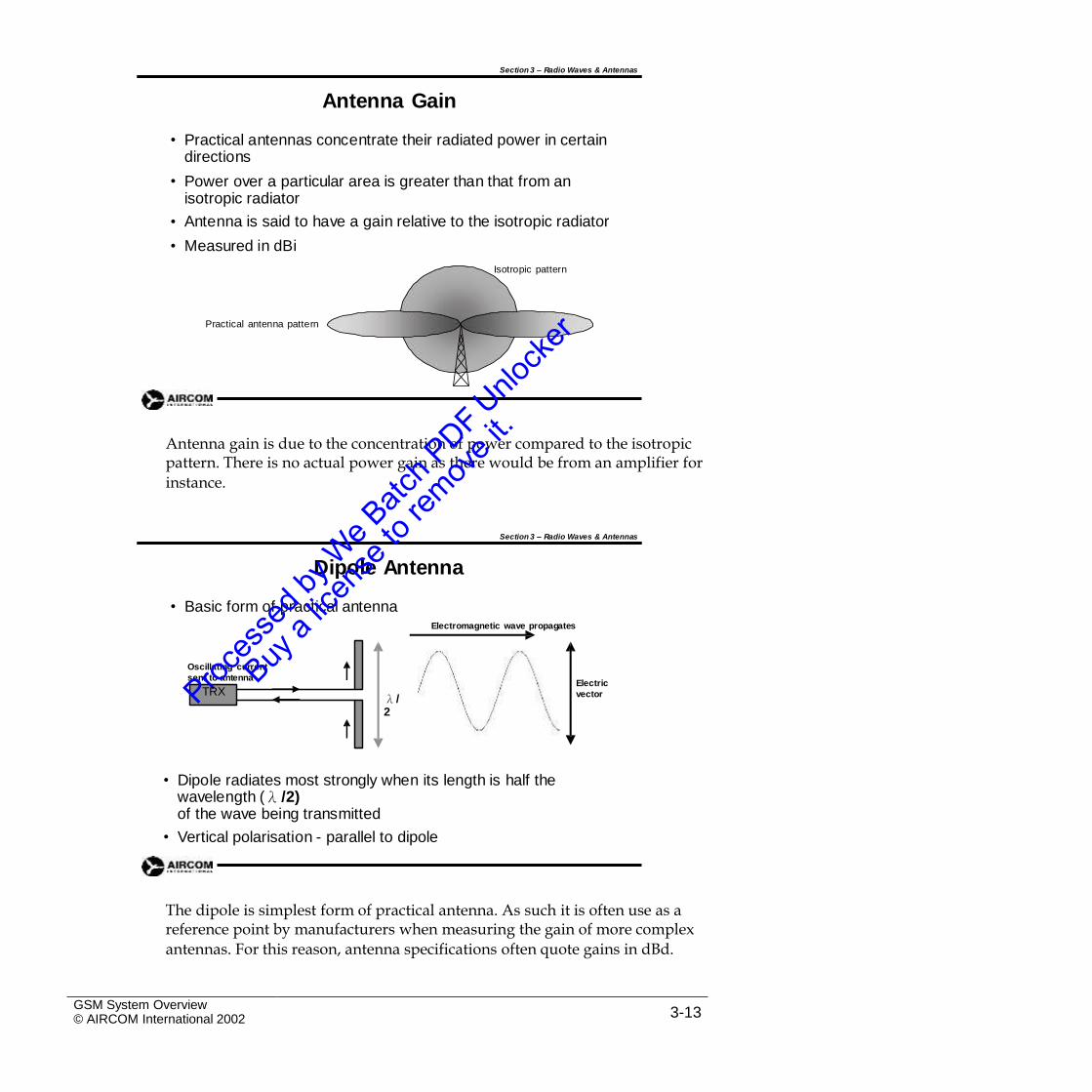
• Practical antennas concentrate their radiated power in certain directions
Power over a particular area is greater than that from an isotropic radiator
Antenna is said to have a gain relative to the isotropic radiator
Measured in dBi
Isotropic pattern
•
•
•
Practical antenna pattern
Antenna gain is due to the concentration of power compared to the isotropicpattern. There is no actual power gain as there would be from an amplifier for
instance.
Section 3 – Radio Waves & Antennas
Dipole Antenna
• Basic form of practical antennaElectromagnetic wave propagates
Oscillating current
sent to antennaElectric
vectorλ/2
• Dipole radiates most strongly when its length is half the wavelength (λ /2)of the wave being transmitted
• Vertical polarisation - parallel to dipole
The dipole is simplest form of practical antenna. As such it is often use as areference point by manufacturers when measuring the gain of more complex
antennas. For this reason, antenna specifications often quote gains in dBd.
GSM System Overview© AIRCOM International 2002 3-13
TRX
Section 3 – Radio Waves & Antennas
Dipole Radiation Pattern
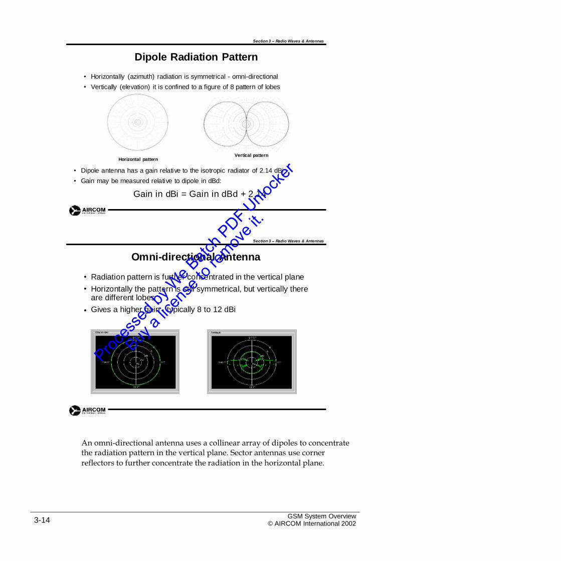
• Horizontally (azimuth) radiation is symmetrical - omni-directional
• Vertically (elevation) it is confined to a figure of 8 pattern of lobes
Vertical patternHorizontal pattern
•
•
Dipole antenna has a gain relative to the isotropic radiator of 2.14 dBi
Gain may be measured relative to dipole in dBd:
Gain in dBi = Gain in dBd + 2.14
Section 3 – Radio Waves & Antennas
Omni-directional Antenna
•
•
Radiation pattern is further concentrated in the vertical plane
Horizontally the pattern is still symmetrical, but vertically there are different lobes
Gives a higher gain - typically 8 to 12 dBi•
An omni-directional antenna uses a collinear array of dipoles to concentratethe radiation pattern in the vertical plane. Sector antennas use corner
reflectors to further concentrate the radiation in the horizontal plane.
GSM System Overview© AIRCOM International 20023-14
Section 3 – Radio Waves & Antennas
Sectored Antenna
•
•
•
•
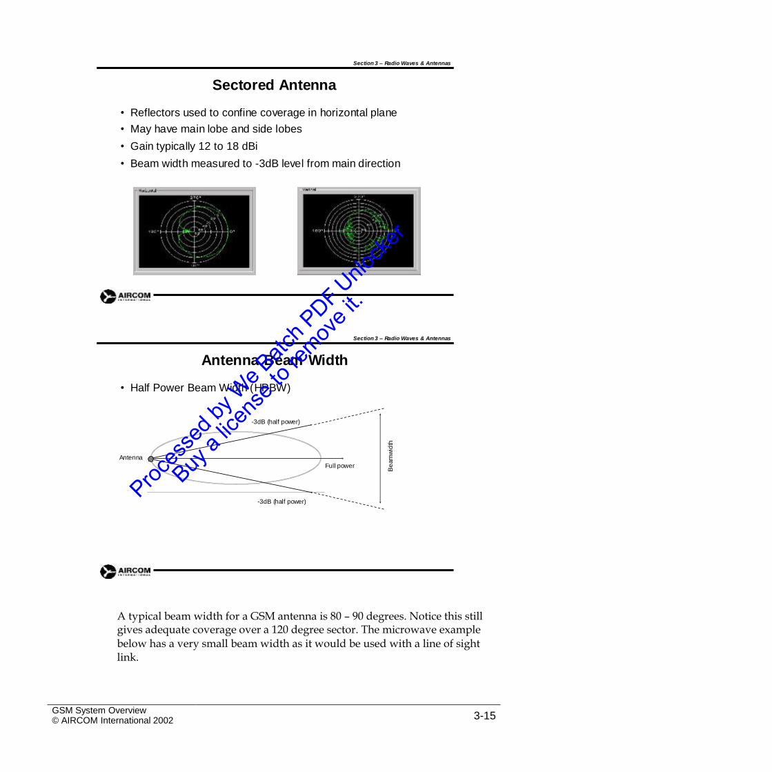
Reflectors used to confine coverage in horizontal plane
May have main lobe and side lobes
Gain typically 12 to 18 dBi
Beam width measured to -3dB level from main direction
Section 3 – Radio Waves & Antennas
Antenna Beam Width
• Half Power Beam Width (HPBW)
-3dB (half power)
Antenna
Full power
-3dB (half power)
A typical beam width for a GSM antenna is 80 – 90 degrees. Notice this stillgives adequate coverage over a 120 degree sector. The microwave example
below has a very small beam width as it would be used with a line of sight link.
GSM System Overview© AIRCOM International 2002 3-15
Be
am
wid
th
Section 3 – Radio Waves & Antennas
Beam Width Example
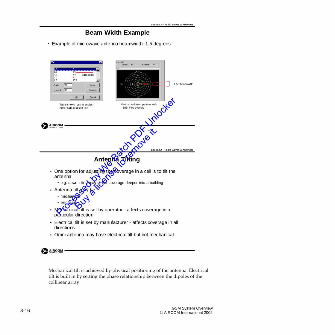
Example of microwave antenna beamwidth: 1.5 degrees•
-3dB point
1.5 o beamwidth
Table shows loss at angles
either s ide of direct line
Vertical radiation pattern with-3dB lines overlaid
Section 3 – Radio Waves & Antennas
Antenna Tilting
• One option for adjusting the coverage in a cell is to tilt the antenna
• e.g. down tilting may direct coverage deeper into a building
Antenna tilt may be:
• mechanical
• electrical
Mechanical tilt is set by operator - affects coverage in a particular direction
Electrical tilt is set by manufacturer - affects coverage in all directions
Omni antenna may have electrical tilt but not mechanical
•
•
•
•
Mechanical tilt is achieved by physical positioning of the antenna. Electricaltilt is built in by setting the phase relationship between the dipoles of the collinear array.
GSM System Overview© AIRCOM International 20023-16
Section 3 – Radio Waves & Antennas
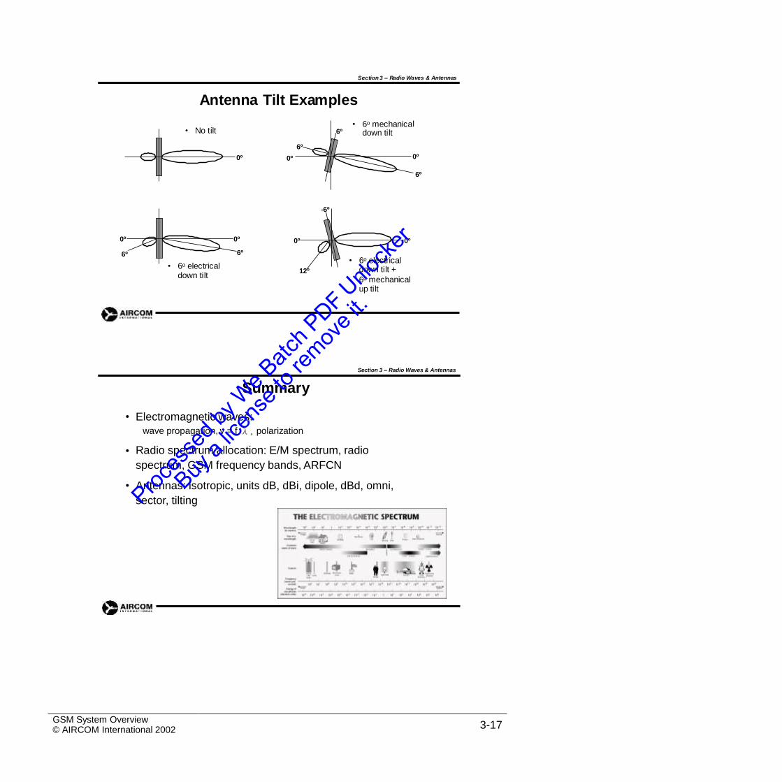
Antenna Tilt Examples
l6º down tilt
0º0º 0º
6º
-6º
0º 0º
6º
0º 0º
6º
• 6o electrical down tilt
down tilt +
6o mechanical up tilt
12º
Section 3 – Radio Waves & Antennas
Summary
• Electromagnetic waves:
wave propagation, v = f λ, polarization
Radio spectrum allocation: E/M spectrum, radio
spectrum, GSM frequency bands, ARFCN
Antennas: isotropic, units dB, dBi, dipole, dBd, omni,
sector, tilting
•
•
GSM System Overview© AIRCOM International 2002 3-17
• 6o electrical
6º
• 6o mechanica• No tilt

Intentional Blank Page
GSM System Overview© AIRCOM International 20023-18
Section 3 Self-Assessment Exercises
Exercise 3.1 – Radio Spectrum Allocation
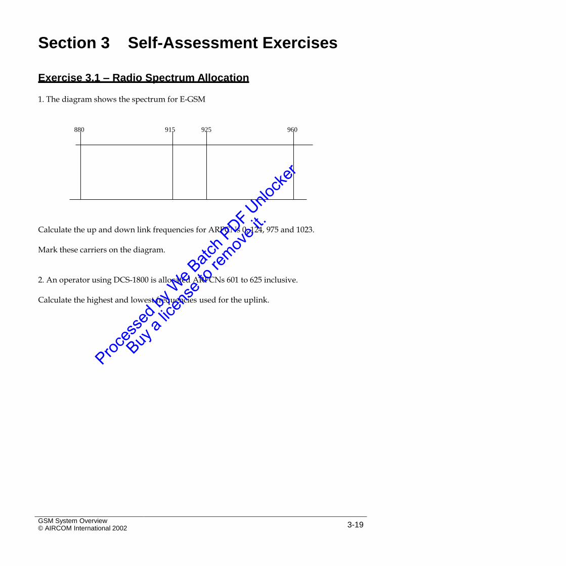
1. The diagram shows the spectrum for E-GSM
880 915 925 960
Calculate the up and down link frequencies for ARFCNs 0, 124, 975 and 1023.
Mark these carriers on the diagram.
2. An operator using DCS-1800 is allocated ARFCNs 601 to 625 inclusive.
Calculate the highest and lowest frequencies used for the uplink.
GSM System Overview© AIRCOM International 2002 3-19
Exercise 3.2 - Antenna Beam Width
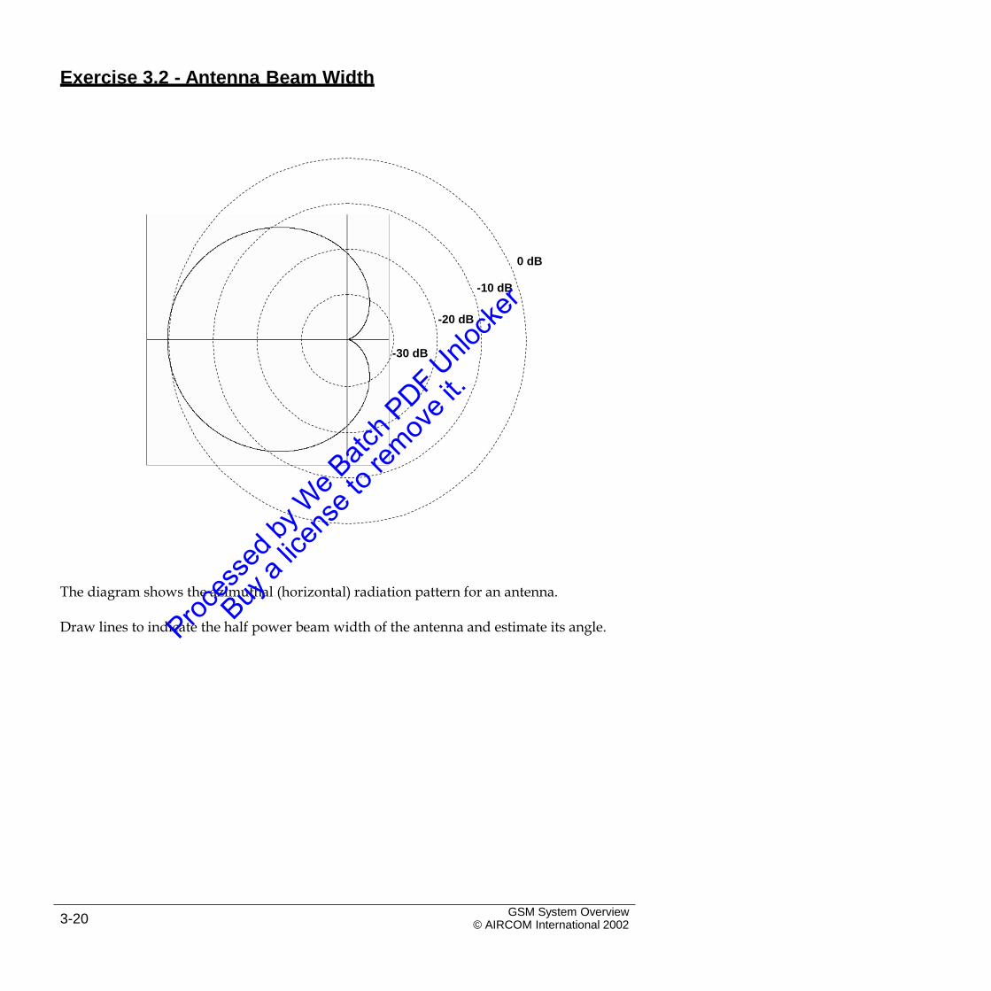
0 dB
-10 dB
-20 dB
-30 dB
The diagram shows the azimuthal (horizontal) radiation pattern for an antenna.
Draw lines to indicate the half power beam width of the antenna and estimate its angle.
GSM System Overview© AIRCOM International 20023-20
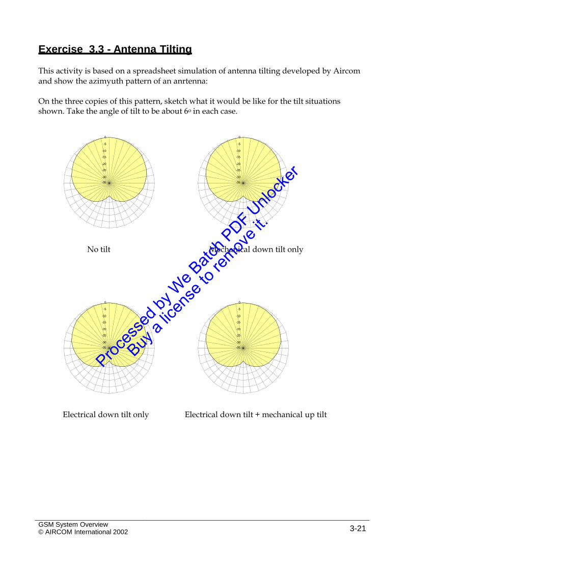
Exercise 3.3 - Antenna Tilting
This activity is based on a spreadsheet simulation of antenna tilting developed by Aircomand show the azimyuth pattern of an anrtenna:
On the three copies of this pattern, sketch what it would be like for the tilt situationsshown. Take the angle of tilt to be about 6o in each case.
0 0
-35 -35
No tilt Mechanical down tilt only
0 0
-35 -35
Electrical down tilt only Electrical down tilt + mechanical up tilt
GSM System Overview© AIRCOM International 2002 3-21
-5
-10
-15
-20
-25
-30
-5
-10
-15
-20
-25
-30
-5
-10
-15
-20
-25
-30
-5
-10
-15
-20
-25
-30
Intentional Blank Page
GSM System Overview© AIRCOM International 20023-22
4. The Air Interface
4.1 Introduction
The air interface or radio interface refers to the manner in whichcommunication is achieved between the mobile handset and the base station.
Modulation techniques allow us to put information onto the radio wave,while multiple access techniques allow us to share the limited resources of the radio spectrum among a number of users.
In GSM there are many signalling and communication activities that must becarried out. These are specified as logical channels, which must be mapped onto the physical channels provided by the radio interface.
This mapping is achieved by using multiframes.
GSM System Overview© AIRCOM International 2002 4-1
4.2 Modulation Techniques
Analogue modulation is useful for illustrating how information can be carriedby a radio wave as it is simple to visualise.
Frequency modulation was used on first generation mobile systems but isvery insecure as it can be intercepted and decoded easily.
Section 4 – The Air Interface
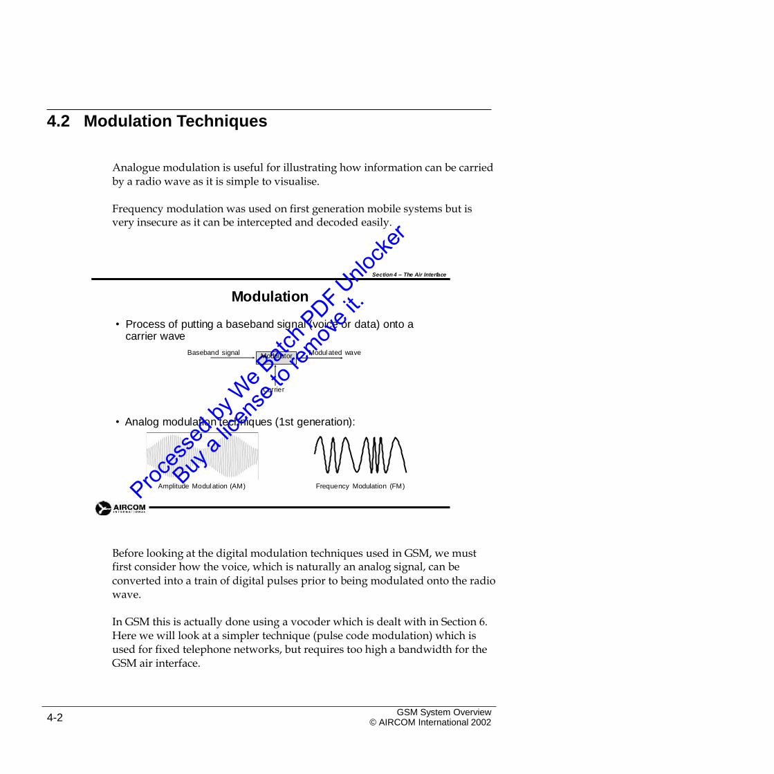
Modulation
• Process of putting a baseband signal (voice or data) onto a carrier wave
Baseband signal Modul ated wave
Carrier
• Analog modulation techniques (1st generation):
Amplitude Modul ation (AM) Frequency Modulation (FM)
Before looking at the digital modulation techniques used in GSM, we mustfirst consider how the voice, which is naturally an analog signal, can be
converted into a train of digital pulses prior to being modulated onto the radio wave.
In GSM this is actually done using a vocoder which is dealt with in Section 6.Here we will look at a simpler technique (pulse code modulation) which is used for fixed telephone networks, but requires too high a bandwidth for the GSM air interface.
GSM System Overview© AIRCOM International 20024-2
Modul ator
Section 4 – The Air Interface
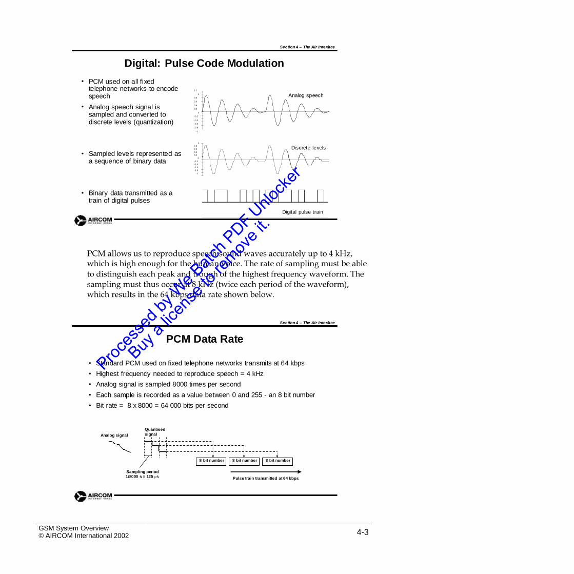
Digital: Pulse Code Modulation
PCM used on all fixed•telephone networks to encode speech
Analog speech signal is sampled and converted to discrete levels (quantization)
1.2
1
0.8
0.6
0.4
0.2
0
-0.2
-0.4
-0.6
-0.8
-1
Analog speech
•
1
0.8
0.6
0.4
0.2
0
-0.2
-0.4
-0.6
-0.8
-1
Discrete levels
• Sampled levels represented as a sequence of binary data
• Binary data transmitted as a train of digital pulses
Digital pulse train
PCM allows us to reproduce speech sound waves accurately up to 4 kHz,which is high enough for the human voice. The rate of sampling must be able
to distinguish each peak and trough of the highest frequency waveform. The sampling must thus occur at 8 kHz (twice each period of the waveform), which results in the 64 kbps data rate shown below.
Section 4 – The Air Interface
PCM Data Rate
•
•
•
•
•
Standard PCM used on fixed telephone networks transmits at 64 kbps
Highest frequency needed to reproduce speech = 4 kHz
Analog signal is sampled 8000 times per second
Each sample is recorded as a value between 0 and 255 - an 8 bit number
Bit rate = 8 x 8000 = 64 000 bits per second
Quantised
signalAnalog signal
Sampling period1/8000 s = 125 µs Pulse train transmitted at 64 kbps
GSM System Overview© AIRCOM International 2002 4-3
8 bit number8 bit number8 bit number
Having turned the speech signal into digital pulses, we now need to modulatethese on to the radio wave. We will first look at a range of techniques known
as shift key modulation.
Section 4 – The Air Interface
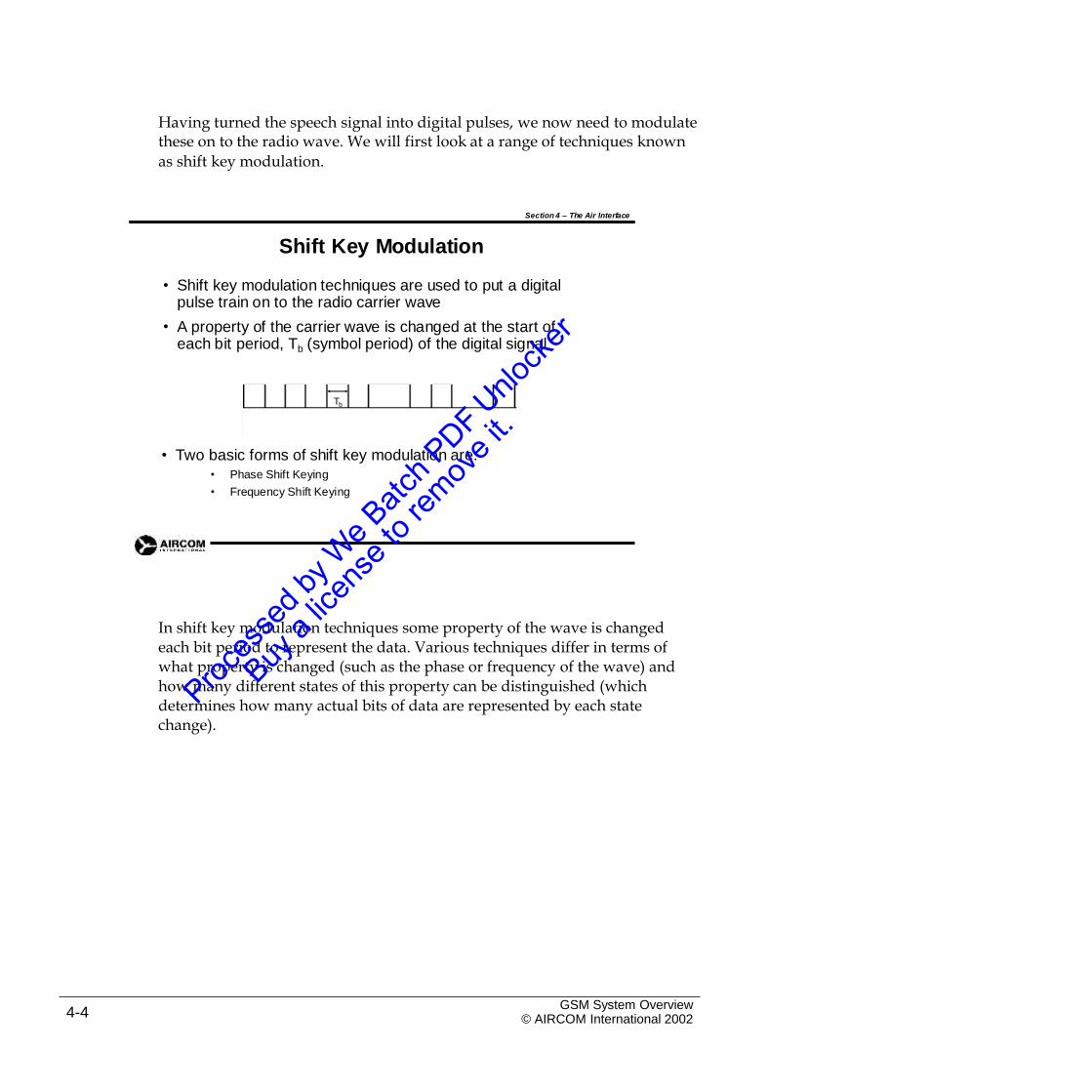
Shift Key Modulation
• Shift key modulation techniques are used to put a digital pulse train on to the radio carrier wave
A property of the carrier wave is changed at the start of each bit period, Tb (symbol period) of the digital signal
•
Tb
• Two basic forms of shift key modulation are:• Phase Shift Keying
• Frequency Shift Keying
In shift key modulation techniques some property of the wave is changedeach bit period to represent the data. Various techniques differ in terms of what property is changed (such as the phase or frequency of the wave) and how many different states of this property can be distinguished (which determines how many actual bits of data are represented by each state change).
GSM System Overview© AIRCOM International 20024-4
Section 4 – The Air Interface
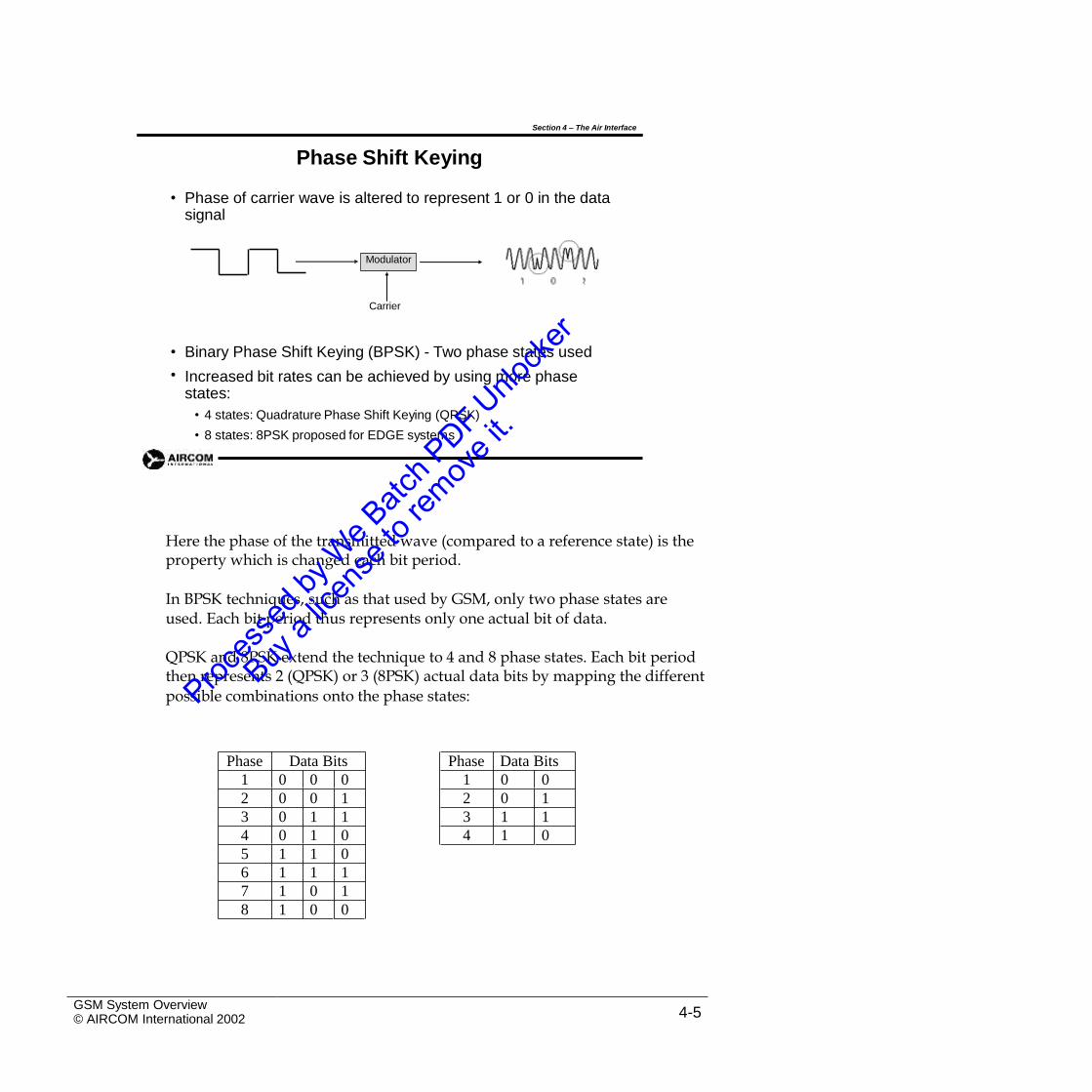
Phase Shift Keying
• Phase of carrier wave is altered to represent 1 or 0 in the data signal
Carrier
•
•
Binary Phase Shift Keying (BPSK) - Two phase states used
Increased bit rates can be achieved by using more phase states:
• 4 states: Quadrature Phase Shift Keying (QPSK)
• 8 states: 8PSK proposed for EDGE systems
Here the phase of the transmitted wave (compared to a reference state) is theproperty which is changed each bit period.
In BPSK techniques, such as that used by GSM, only two phase states areused. Each bit period thus represents only one actual bit of data.
QPSK and 8PSK extend the technique to 4 and 8 phase states. Each bit periodthen represents 2 (QPSK) or 3 (8PSK) actual data bits by mapping the different
possible combinations onto the phase states:
GSM System Overview© AIRCOM International 2002 4-5
Phase Data Bits
1 0 0
2 0 1
3 1 1
4 1 0
Phase Data Bits
1 0 0 0
2 0 0 1
3 0 1 1
4 0 1 0
5 1 1 0
6 1 1 1
7 1 0 1
8 1 0 0
Modulator
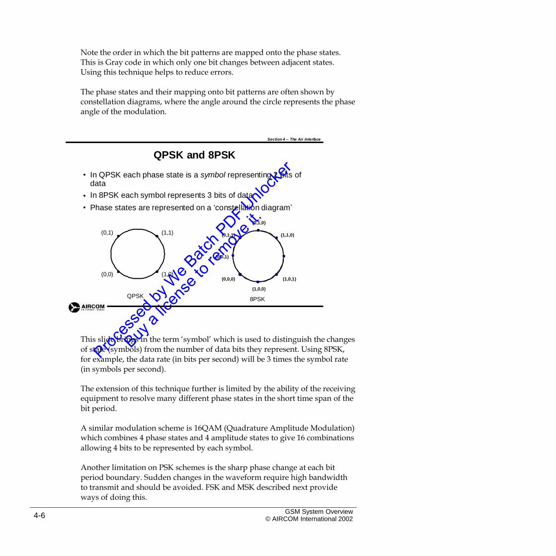
Note the order in which the bit patterns are mapped onto the phase states.This is Gray code in which only one bit changes between adjacent states. Using this technique helps to reduce errors.
The phase states and their mapping onto bit patterns are often shown byconstellation diagrams, where the angle around the circle represents the phase angle of the modulation.
Section 4 – The Air Interface
QPSK and 8PSK
• In QPSK each phase state is a symbol representing 2 bits of data
In 8PSK each symbol represents 3 bits of data
Phase states are represented on a ‘constellation diagram’
•
•
(0,1,0)
(0,1) (1,1) (0,1,1) (1,1,0)
(0,0,1)
(0,0) (1,0)(0,0,0) (1,0,1)
(1,0,0)
QPSK8PSK
This slide brings in the term ‘symbol’ which is used to distinguish the changesof state (symbols) from the number of data bits they represent. Using 8PSK, for example, the data rate (in bits per second) will be 3 times the symbol rate (in symbols per second).
The extension of this technique further is limited by the ability of the receivingequipment to resolve many different phase states in the short time span of the
bit period.
A similar modulation scheme is 16QAM (Quadrature Amplitude Modulation)which combines 4 phase states and 4 amplitude states to give 16 combinations
allowing 4 bits to be represented by each symbol.
Another limitation on PSK schemes is the sharp phase change at each bitperiod boundary. Sudden changes in the waveform require high bandwidth to transmit and should be avoided. FSK and MSK described next provide ways of doing this.
GSM System Overview© AIRCOM International 20024-6
Section 4 – The Air Interface
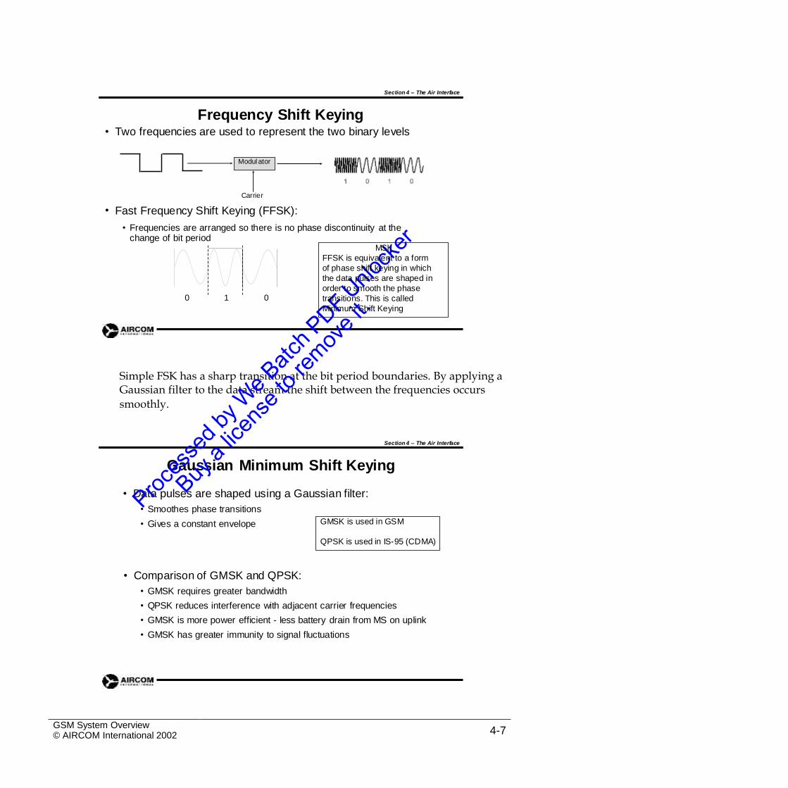
Frequency Shift KeyingTwo frequencies are used to represent the two binary levels•
Carrier
Fast Frequency Shift Keying (FFSK):
• Frequencies are arranged so there is no phase discontinuity at the change of bit period
•
0 1 0
Simple FSK has a sharp transition at the bit period boundaries. By applying aGaussian filter to the data stream the shift between the frequencies occurs
smoothly.
Section 4 – The Air Interface
Gaussian Minimum Shift Keying
• Data pulses are shaped using a Gaussian filter:
• Smoothes phase transitions
• Gives a constant envelope
• Comparison of GMSK and QPSK:
• GMSK requires greater bandwidth
• QPSK reduces interference with adjacent carrier frequencies
• GMSK is more power efficient - less battery drain from MS on uplink
• GMSK has greater immunity to signal fluctuations
GSM System Overview© AIRCOM International 2002 4-7
GMSK is used in GSM
QPSK is used in IS-95 (CDMA)
MSK
FFSK is equivalent to a form
of phase shift keying in which
the data pulses are shaped in
order to smooth the phase
transitions. This is called
Minimum Shift Keying
Modul ator
Section 4 – The Air Interface
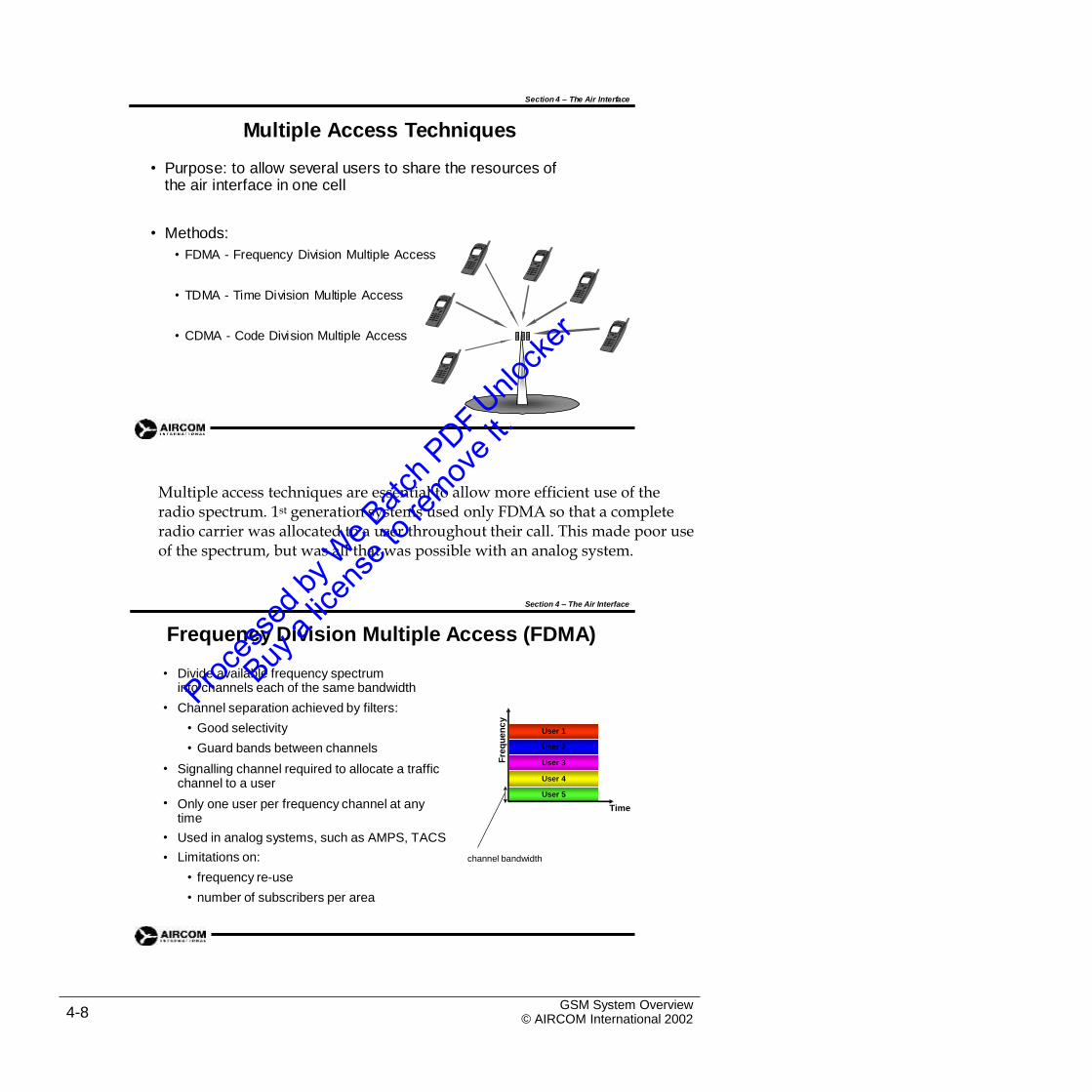
Multiple Access Techniques
• Purpose: to allow several users to share the resources of the air interface in one cell
• Methods:
• FDMA - Frequency Division Multiple Access
• TDMA - Time Division Multiple Access
• CDMA - Code Division Multiple Access
Multiple access techniques are essential to allow more efficient use of theradio spectrum. 1st generation systems used only FDMA so that a complete radio carrier was allocated to a user throughout their call. This made poor use of the spectrum, but was all that was possible with an analog system.
Section 4 – The Air Interface
Frequency Division Multiple Access (FDMA)
• Divide available frequency spectruminto channels each of the same bandwidth
Channel separation achieved by filters:
• Good selectivity
• Guard bands between channels
Signalling channel required to allocate a traffic channel to a user
Only one user per frequency channel at any time
Used in analog systems, such as AMPS, TACS
Limitations on:
• frequency re-use
• number of subscribers per area
•
User 1
User 2
User 3•
User 4
User 5
• Time
•
• channel bandwidth
GSM System Overview© AIRCOM International 20024-8
Fre
qu
en
cy
Section 4 – The Air Interface
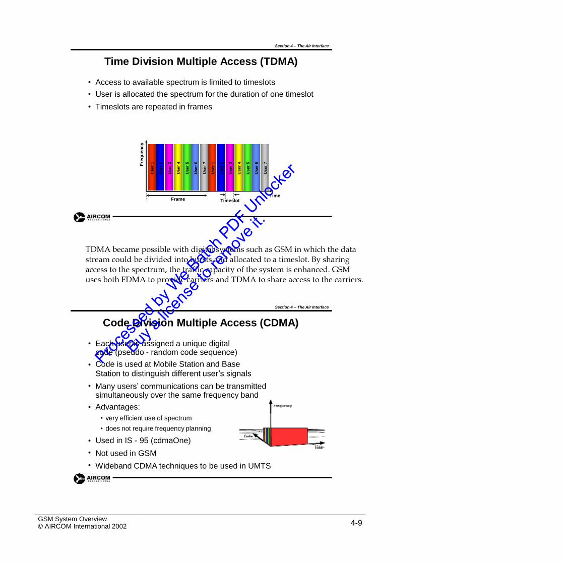
Time Division Multiple Access (TDMA)
•
•
•
Access to available spectrum is limited to timeslots
User is allocated the spectrum for the duration of one timeslot
Timeslots are repeated in frames
TimeFrame Timeslot
TDMA became possible with digital systems such as GSM in which the datastream could be divided into bursts and allocated to a timeslot. By sharing access to the spectrum, the traffic capacity of the system is enhanced. GSM uses both FDMA to provide carriers and TDMA to share access to the carriers.
Section 4 – The Air Interface
Code Division Multiple Access (CDMA)
• Each user is assigned a unique digital code (pseudo - random code sequence)
Code is used at Mobile Station and BaseStation to distinguish different user’s signals
Many users’ communications can be transmitted simultaneously over the same frequency band
Advantages:
• very efficient use of spectrum
• does not require frequency planning
Used in IS - 95 (cdmaOne)
Not used in GSM
Wideband CDMA techniques to be used in UMTS
•
•
•
•
•
•
GSM System Overview© AIRCOM International 2002 4-9
Fre
qu
en
cy
Use
r1
Use
r2
Use
r3
Use
r4
Use
r5
Use
r6
Use
r7
Use
r1
Use
r2
Use
r3
Use
r4
Use
r5
Use
r6
Use
r7
TCH
Traffic
TCH/H
TCH/F
CCCH
Contr ol
BCH DCCH
FCCH
SCH
BCCH
PCH
RACH
AGCH
CBCH
NCH
SDCCH
SACCH
FACCH
4.3 GSM Channels
Section 4 – The Air Interface
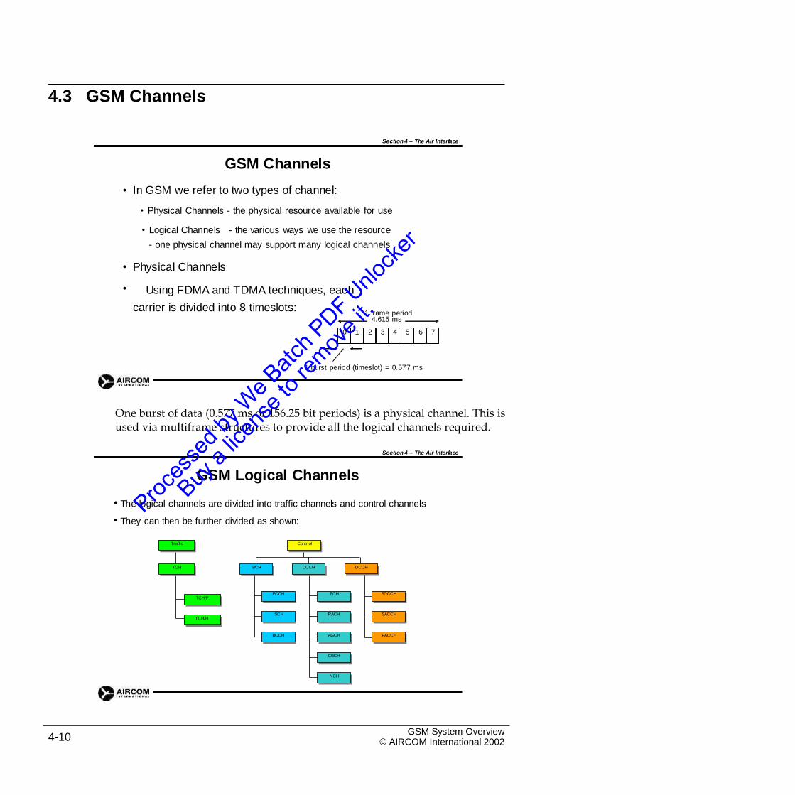
GSM Channels
In GSM we refer to two types of channel:
• Physical Channels - the physical resource available for use
•
• Logical Channels - the various ways we use the resource
- one physical channel may support many logical channels
•
•
Physical Channels
Using FDMA and TDMA techniques, each
carrier is divided into 8 timeslots:1 frame period
1 burst period (timeslot) = 0.577 ms
One burst of data (0.577 ms or 156.25 bit periods) is a physical channel. This isused via multiframe structures to provide all the logical channels required.
Section 4 – The Air Interface
GSM Logical Channels
• The logical channels are divided into traffic channels and control channels
• They can then be further divided as shown:
GSM System Overview© AIRCOM International 20024-10
Contr ol
BCH CCCH DCCH
FCCH PCH SDCCH
SCH RACH SACCH
BCCH AGCH FACCH
CBCH
NCH
Traffic
TCH
TCH/F
TCH/H
4.615 ms
0 1 2 3 4 5 6 7
The naming of the GSM logical channels is as follows:
TCHTCH/FTCH/H
Traffic ChannelsTraffic Channel (full rate) (U/D)Traffic Channel (half rate) (U/D)
BCHFCCH
SCH BCCH
Broadcast ChannelsFrequency Correction Channel (D)
Synchronisation Channel (D) Broadcast Control Channel (D)
CCCHPCHRACH
AGCHCBCHNCH
Common Control ChannelsPaging Channel (D)Random Access Channel (U)
Access Grant Channel (D)
Cell Broadcast Channel (D)
Notification Channel (D)
DCCHSDCCH
SACCH FACCH
Dedicated Control ChannelsStand alone Dedicated Control Channel (U/D)
Slow Associated Control Channel (U/D) Fast Associated Control Channel (U/D)
U = Uplink D = Downlink
The purpose of these channels is outlined in the next four slides.
Section 4 – The Air Interface
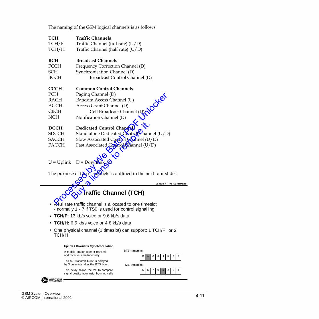
Traffic Channel (TCH)
• A full rate traffic channel is allocated to one timeslot- normally 1 - 7 if TS0 is used for control signalling
TCH/F: 13 kb/s voice or 9.6 kb/s data
TCH/H: 6.5 kb/s voice or 4.8 kb/s data
One physical channel (1 timeslot) can support: 1 TCH/F TCH/H
•
•
• or 2
Uplink / Downlink Synchroni sation
A mobile station cannot transmit
and recei ve simultaneously.
The MS transmit burst is delayed
by 3 timeslots after the BTS burst.
This delay allows the MS to compare
signal quality from neighbouri ng cells
BTS transmits:
MS transmits:
GSM System Overview© AIRCOM International 2002 4-11
5 6 7 0 1 2 3 4
0 1 2 3 4 5 6 7
Half rate TCH is not generally implemented.
The delay between uplink and downlink is generally less than 3 timeslots dueto Timing Advance. This is covered in course G103 (Advanced GSM Cell
Planning).
Section 4 – The Air Interface
Broadcast Channels (BCH)
BCH channels are all downlink and are allocated totimeslot zero. BCH channels include:
• FCCH: Frequency Control CHannel sends the mobile a burst of all ‘0’ bits which allows it to fine tune to the downlink frequency
SCH: Synchronisation CHannel sends the absolute valueof the frame number (FN), which is the internal clock of theBTS, together with the Base Station Identity Code (BSIC)
BCCH: Broadcast Control CHannel sends radio resource management and control messages, Location Area Code and so on. Some messages go to all mobiles, others just to those that are in the idle state
•
•
Section 4 – The Air Interface
Common Control Channels (CCCH)
CCCH contains all point to multi-point downlink channels (BTS to several MSs) and the uplink Random Access Channel:
• CBCH: Cell Broadcast CHannel is an optional channel for general
information such as road traffic reports sent in the form of SMS
• PCH: Paging CHannel sends paging signal to inform mobile of a call
• RACH: Random Access CHannel is sent by the MS to request a channel from the BTS or accept a handover to another BTS.A channel request is sent in response to a PCH message.
• AGCH: Access Grant CHannel allocates a dedicated channel
(SDCCH) to the mobile
• NCH: Notification CHannel informs MS about incoming group or
broadcast calls
GSM System Overview© AIRCOM International 20024-12
Section 4 – The Air Interface
Dedicated Control Channels (DCCH)
DCCH comprise the following bi-directional (uplink / downlink)point to point control channels:
• SDCCH: Standalone Dedicated CHannel is used for call
set up, location updating and also SMS
SACCH: Slow Associated Control CHannel is used for link
measurements and signalling during a call
FACCH: Fast Associated Control CHannel is used (when
needed) for signalling during a call, mainly for delivering
handover messages and for acknowledgement when a
TCH is assigned
•
•
Section 4 – The Air Interface
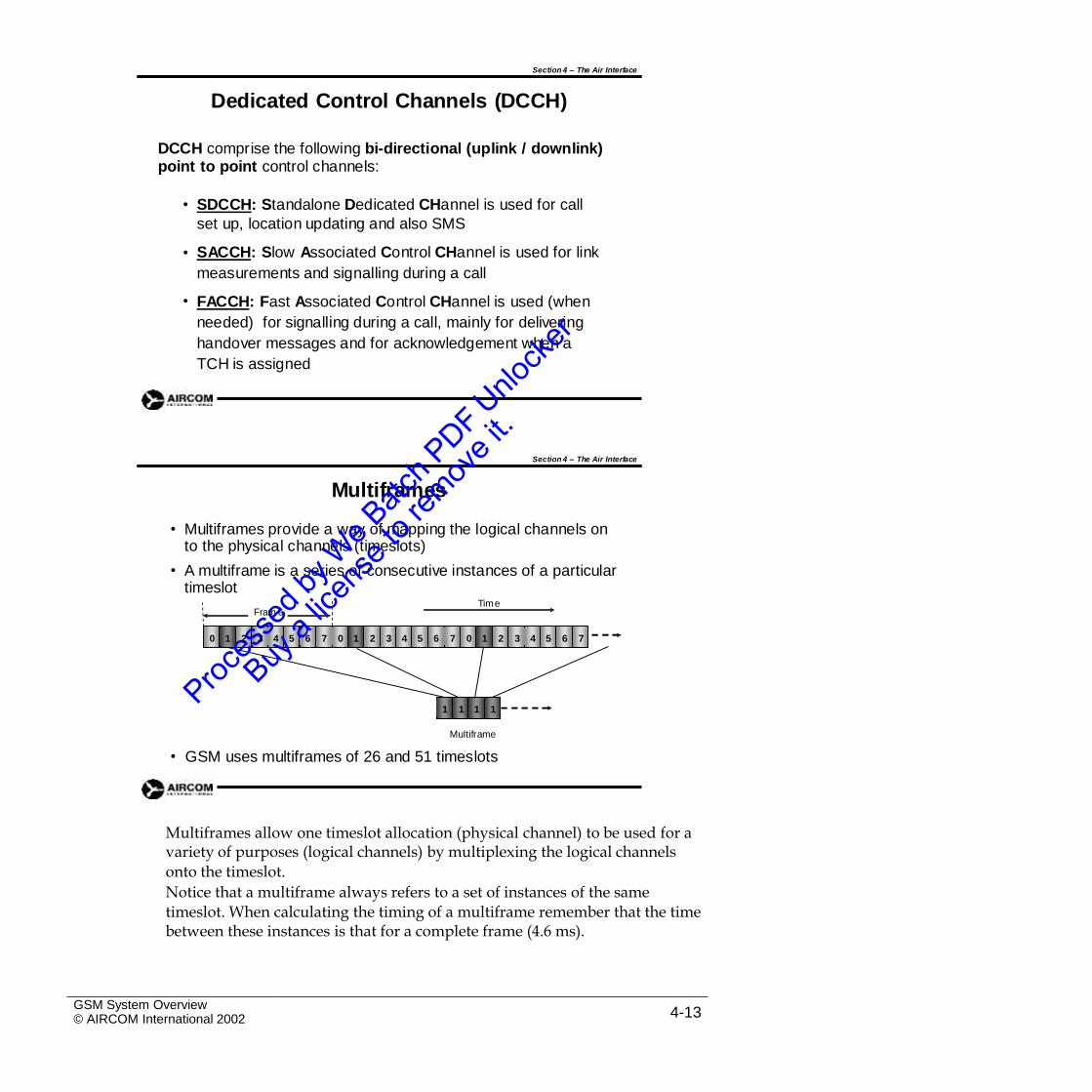
Multiframes
• Multiframes provide a way of mapping the logical channels on to the physical channels (timeslots)
A multiframe is a series of consecutive instances of a particular timeslot
•
Time
Multiframe
GSM uses multiframes of 26 and 51 timeslots•
Multiframes allow one timeslot allocation (physical channel) to be used for avariety of purposes (logical channels) by multiplexing the logical channels
onto the timeslot.
Notice that a multiframe always refers to a set of instances of the same
timeslot. When calculating the timing of a multiframe remember that the time between these instances is that for a complete frame (4.6 ms).
GSM System Overview© AIRCOM International 2002 4-13
1 1 1 1
Fram e
0 1 2 3 4 5 6 7 0 1 2 3 4 5 6 7 0 1 2 3 4 5 6 7
Section 4 – The Air Interface
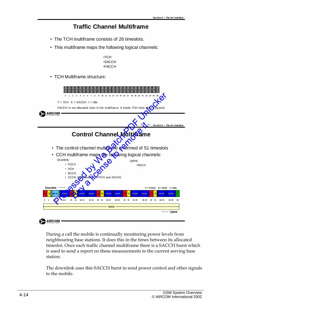
Traffic Channel Multiframe
•
•
The TCH multiframe consists of 26 timeslots.
This multiframe maps the following logical channels:
•TCH
•SACCH
•FACCH
• TCH Multiframe structure:
0 1 2 3 4 5 6 7 8 9 10 11 12 13 14 15 16 17 18 19 20 21 22 23 24 25
T = TCH S = SACCH I = Idle
FACCH is not allocated slots in the multifram e. It steals TCH slots when required.
Section 4 – The Air Interface
Control Channel Multiframe
• The control channel multiframe is formed of 51 timeslots
• CCH multiframe maps the following logical channels:Downlink: Uplink:
•RACH• FCCH
SCH
BCCH
•
•
• CCCH (combination of PCH and AGCH)
Downlink F = FCCH S = SCH I = Idle
0 1 2-5 6-9 10 11 12- 15 16- 19 20 21 22- 25 26- 29 30 31 32- 35 36- 39 40 41 42- 45 46- 49 50
Uplink
During a call the mobile is continually monitoring power levels fromneighbouring base stations. It does this in the times between its allocated timeslot. Once each traffic channel multiframe there is a SACCH burst which is used to send a report on these measurements to the current serving base station.
The downlink uses this SACCH burst to send power control and other signalsto the mobile.
GSM System Overview© AIRCOM International 20024-14
RACH
F S BCCH CCCH F S CCCH CCCH F S CCCH CCCH F S CCCH CCCH F S CCCH CCCH I
T T T T T T T T T T T T S T T T T T T T T T T T T I
The idle slot (25) occurs to allow for half rate TCH/H operation in which twomobiles would share the multiframe and sets of reports would need to be sent to the base station. Slot 25 would then be a second SACCH burst.
FACCH is used for purposes that require instant access such as a handovercommand message from the base station. When this is needed, FACCH uses a TCH burst and sets a ‘stealing flag’ in the burst to show that it is not a traffic channel burst.
Control channel multiframes always consist of 51 timeslots and are generallyallocated to timeslot 0 (TS0) in the frame.
The example shown is for TS0 of the BCCH carrier. It includes 9 blocks ofCCCH, which will be used for PCH and AGCH. It is possible to replace some CCCH blocks with SDCCH forming a combined multiframe. If more SDCCH is required than can be allocated in this way, then a second timeslot is used (generally TS0 of another carrier) leaving the BCCH as the non-combined multiframe shown above.
The structure of control channel multiframes and the methods of calculatingthe allocation required for a particular cell are dealt with in course G103 (Advanced GSM Cell Planning).
Section 4 – The Air Interface
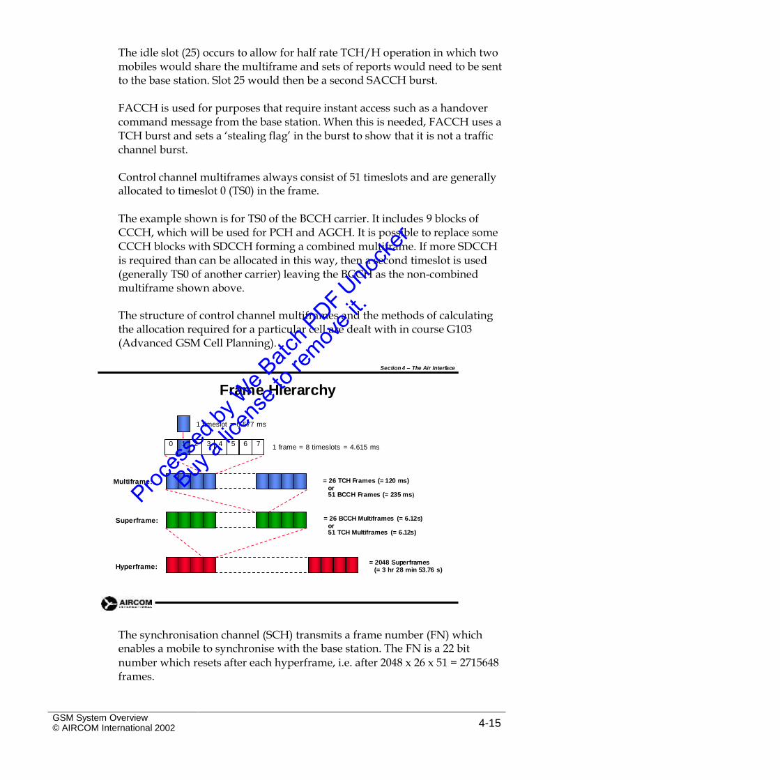
Frame Hierarchy
1 timeslot = 0.577 ms
1 frame = 8 timeslots = 4.615 ms
= 26 TCH Frames (= 120 ms)or51 BCCH Frames (= 235 ms)
Multiframe:
= 26 BCCH Multiframes (= 6.12s)or51 TCH Multiframes (= 6.12s)
Superframe:
= 2048 Superframes(= 3 hr 28 min 53.76 s)Hyperframe:
The synchronisation channel (SCH) transmits a frame number (FN) whichenables a mobile to synchronise with the base station. The FN is a 22 bit
number which resets after each hyperframe, i.e. after 2048 x 26 x 51 = 2715648 frames.
GSM System Overview© AIRCOM International 2002 4-15
0 1 2 3 4 5 6 7
TCH
Traffic
TCH/H
TCH/F
CCCH
Control
BCH DCCH
FCCH
SCH
BCCH
PCH
RACH
AGCH
CBCH
NCH
SDCCH
SACCH
FACCH
Section 4 – The Air Interface
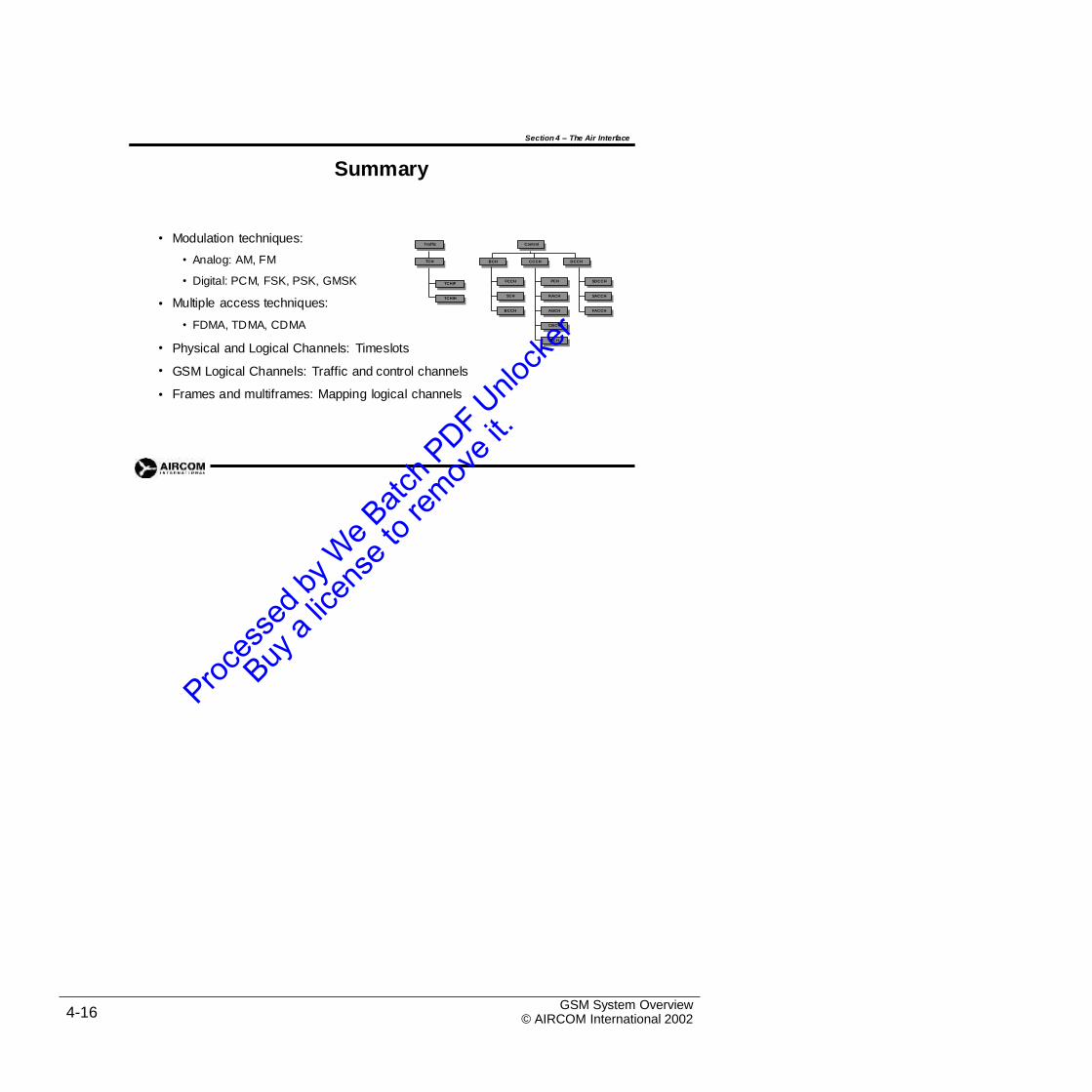
Summary
• Modulation techniques:
• Analog: AM, FM
• Digital: PCM, FSK, PSK, GMSK
Multiple access techniques:
• FDMA, TDMA, CDMA
Physical and Logical Channels: Timeslots
•
•
•
•
GSM Logical Channels: Traffic and control channels
Frames and multiframes: Mapping logical channels
GSM System Overview© AIRCOM International 20024-16
DCCH
SDCCH
SACCH
FACCH
BCH
FCCH
SCH
BCCH
Control
CCCH
PCH
RACH
AGCH
CBCH
NCH
Traffic
TCH
TCH/F
TCH/H
Section 4 Self-Assessment Exercises
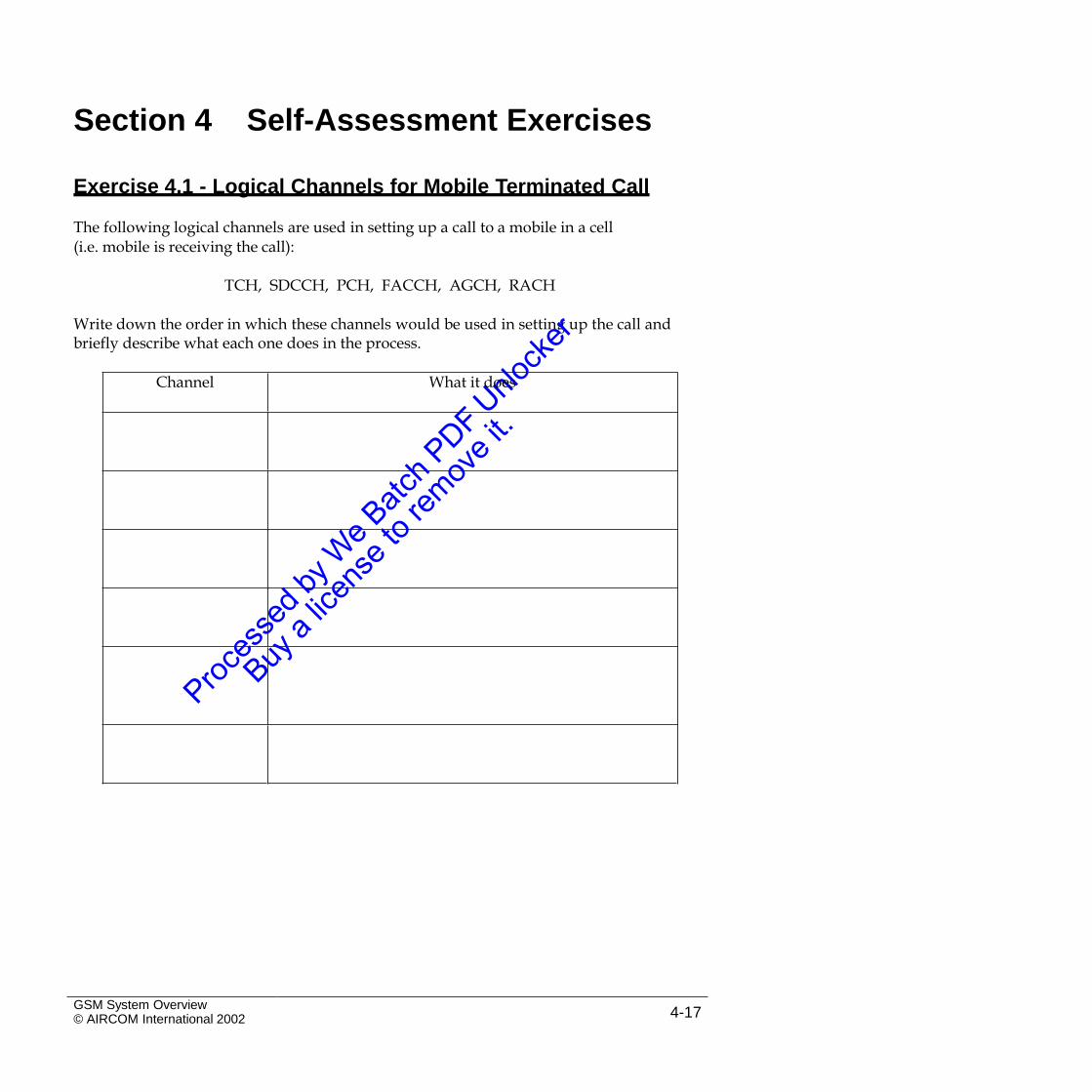
Exercise 4.1 - Logical Channels for Mobile Terminated Call
The following logical channels are used in setting up a call to a mobile in a cell(i.e. mobile is receiving the call):
TCH, SDCCH, PCH, FACCH, AGCH, RACH
Write down the order in which these channels would be used in setting up the call andbriefly describe what each one does in the process.
GSM System Overview© AIRCOM International 2002 4-17
Channel What it does

Intentional Blank Page
GSM System Overview© AIRCOM International 20024-18
5. Protocols
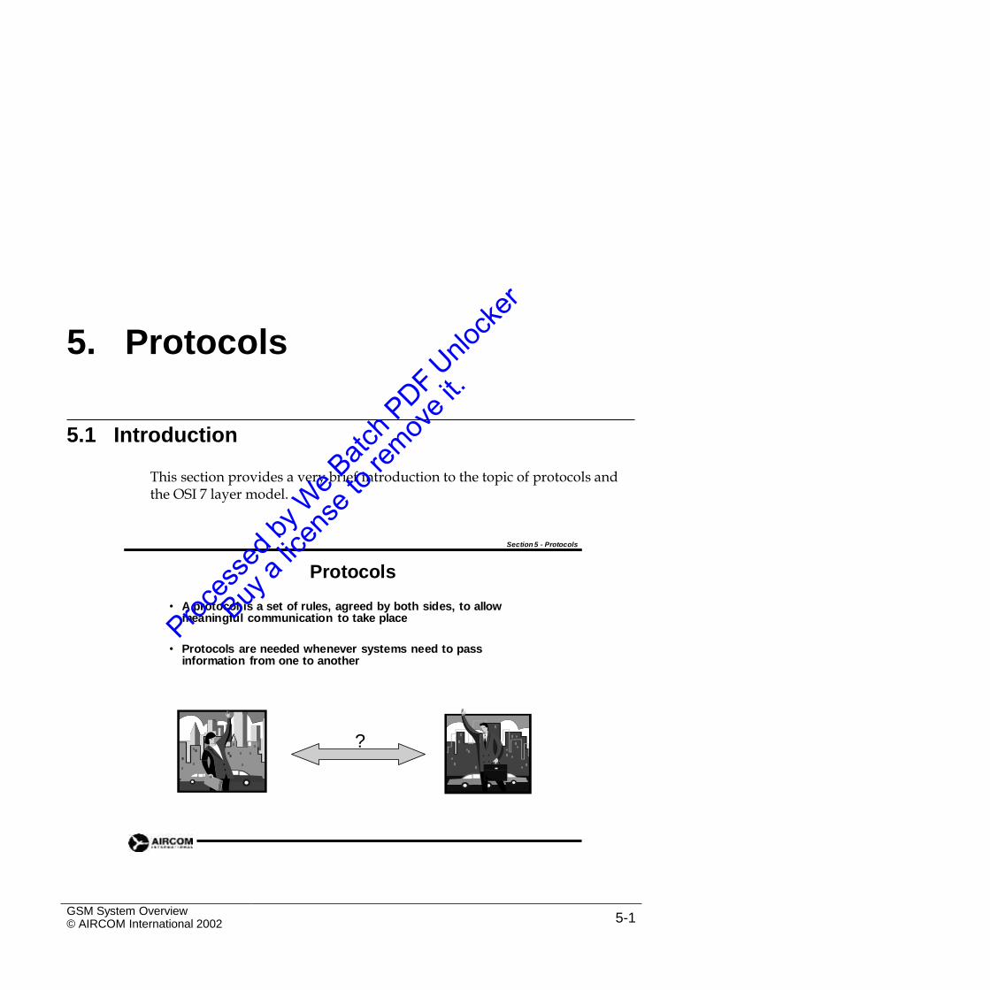
5.1 Introduction
This section provides a very brief introduction to the topic of protocols andthe OSI 7 layer model.
Section 5 - Protocols
Protocols
• A protocol is a set of rules, agreed by both sides, to allow meaningful communication to take place
• Protocols are needed whenever systems need to pass information from one to another
?
GSM System Overview© AIRCOM International 2002 5-1
5.2 The ISO 7-Layer OSI Model
Section 5 - Protocols
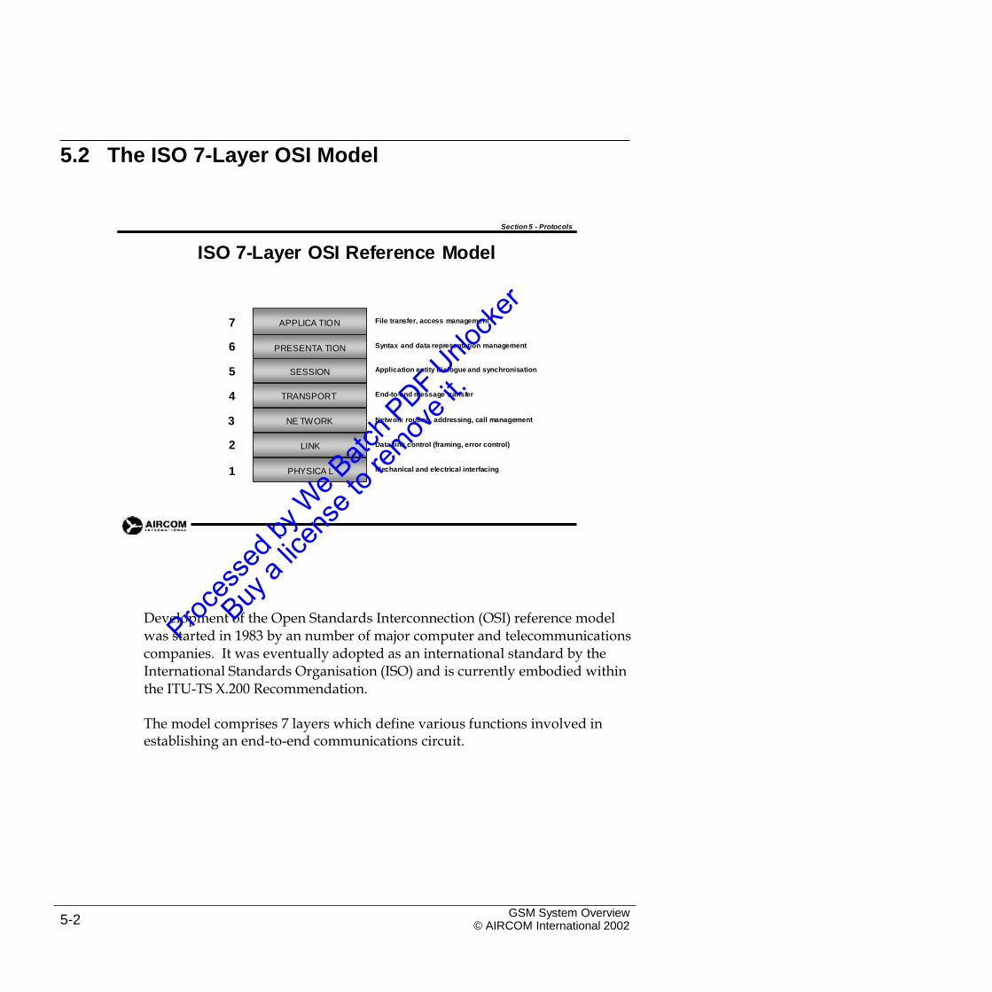
ISO 7-Layer OSI Reference Model
7 File transfer, access management
6 Syntax and data representation management
5 Application entity dialogue and synchronisation
4 End-to-end message transfer
3 Network routing, addressing, call management
2 Data link control (framing, error control)
1 Mechanical and electrical interfacing
Development of the Open Standards Interconnection (OSI) reference modelwas started in 1983 by an number of major computer and telecommunications companies. It was eventually adopted as an international standard by the International Standards Organisation (ISO) and is currently embodied within the ITU-TS X.200 Recommendation.
The model comprises 7 layers which define various functions involved inestablishing an end-to-end communications circuit.
GSM System Overview© AIRCOM International 20025-2
APPLICA TION
PRESENTA TION
SESSION
TRANSPORT
NE TWORK
LINK
PHYSICA L
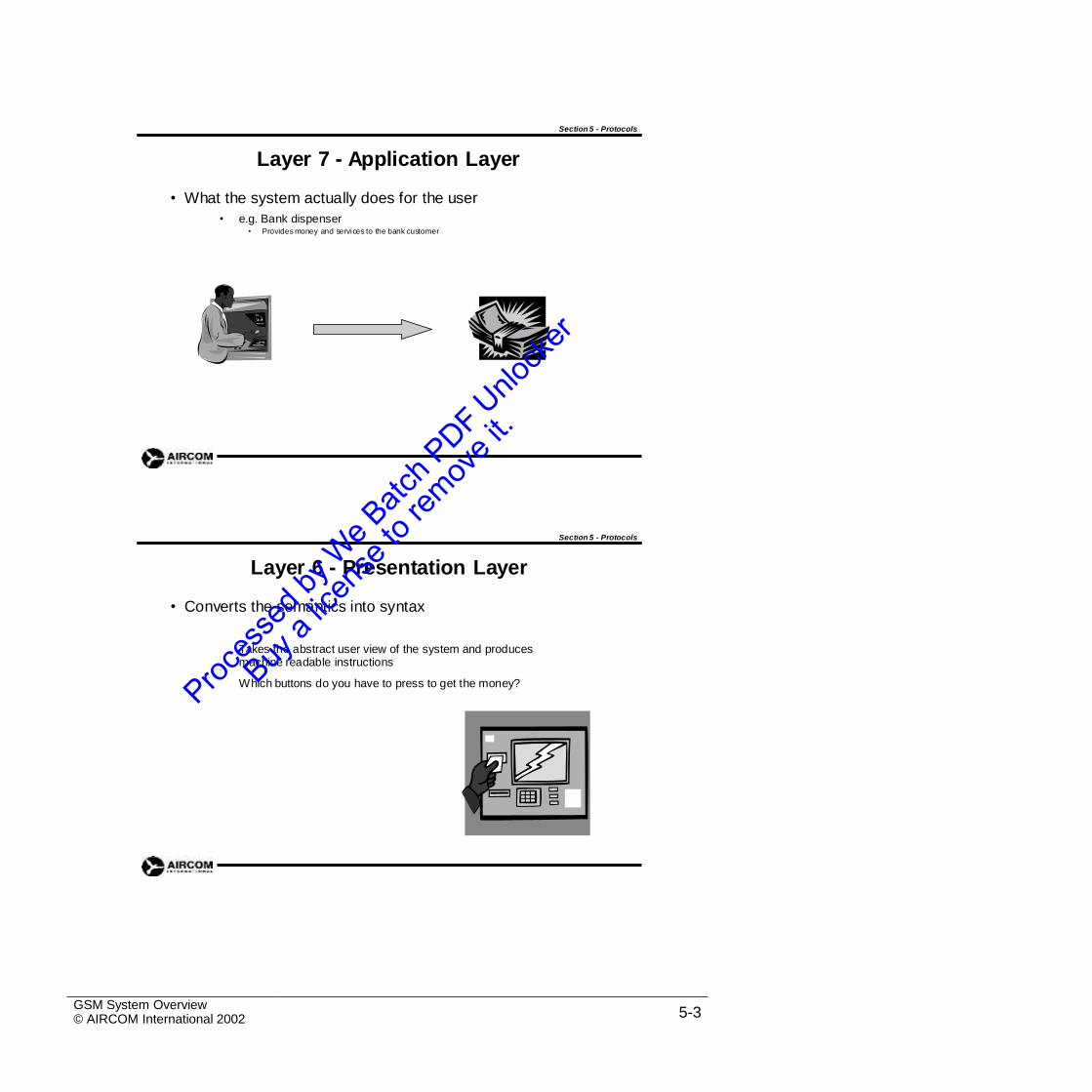
Section 5 - Protocols
Layer 7 - Application Layer
• What the system actually does for the user
• e.g. Bank dispenser• Provides money and services to the bank customer
Section 5 - Protocols
Layer 6 - Presentation Layer
• Converts the semantics into syntax
Takes the abstract user view of the system and produces machine readable instructions
Which buttons do you have to press to get the money?
GSM System Overview© AIRCOM International 2002 5-3
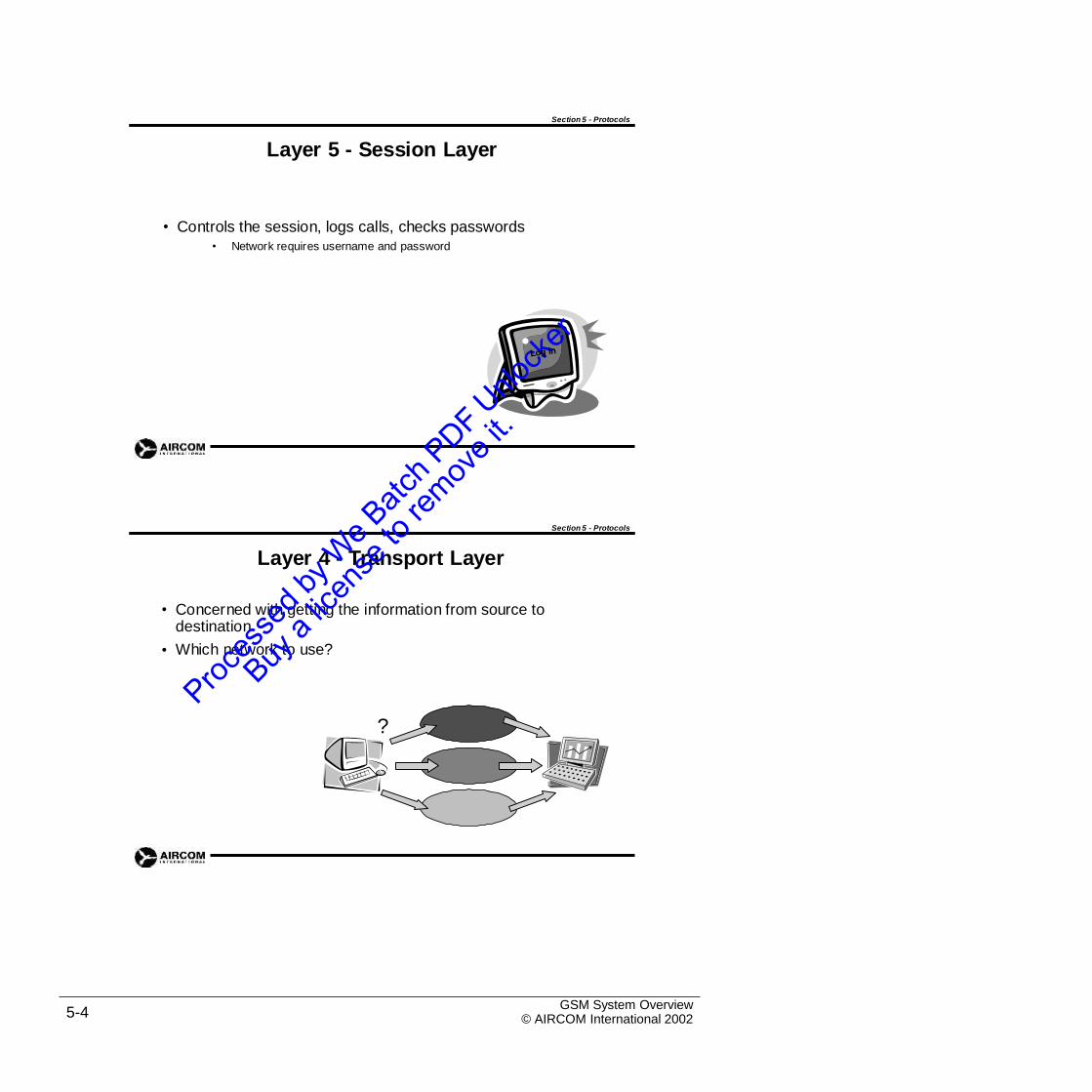
Section 5 - Protocols
Layer 5 - Session Layer
• Controls the session, logs calls, checks passwords• Network requires username and password
Section 5 - Protocols
Layer 4 - Transport Layer
• Concerned with getting the information from source to destination
Which network to use?•
?
GSM System Overview© AIRCOM International 20025-4
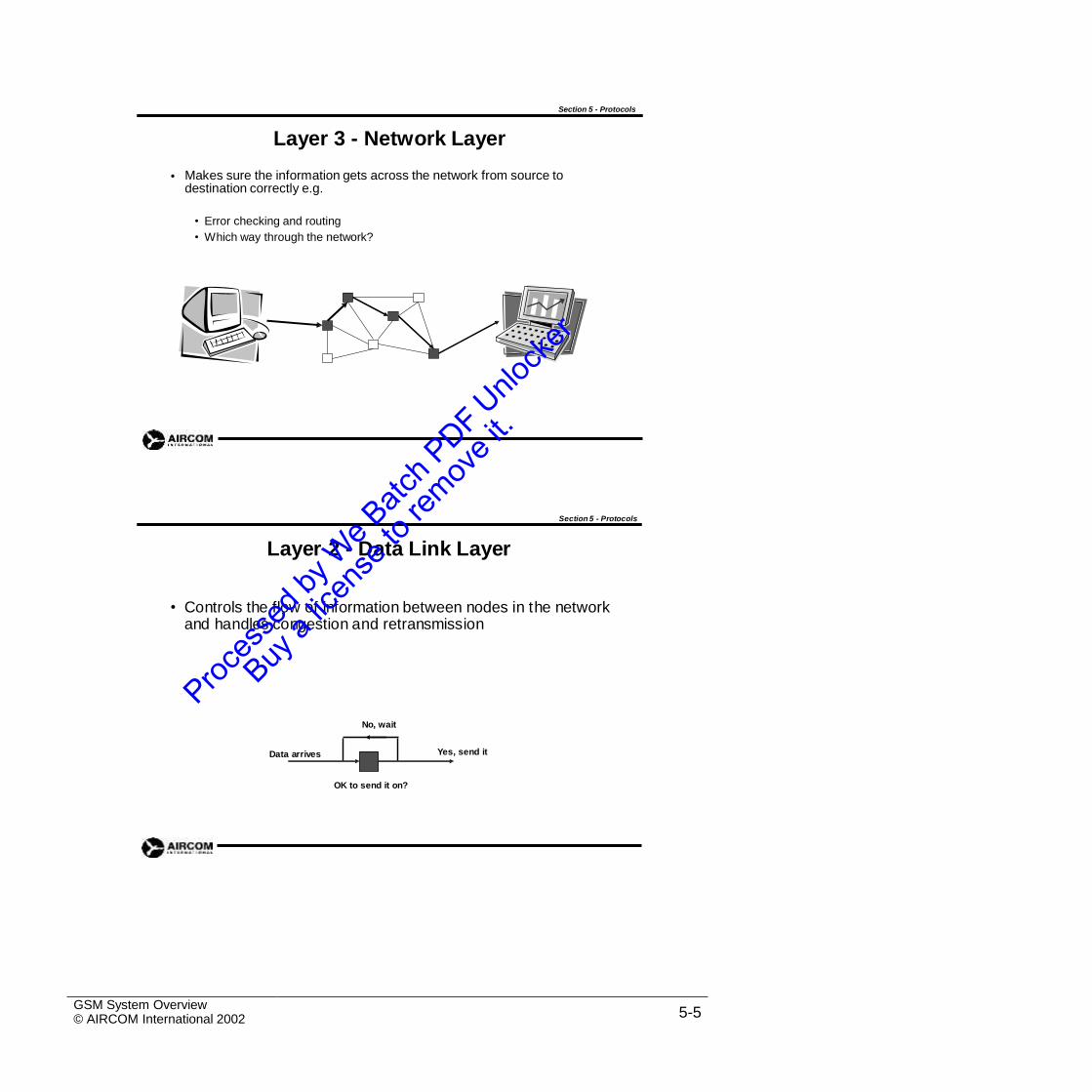
Section 5 - Protocols
Layer 3 - Network Layer
Makes sure the information gets across the network from source to destination correctly e.g.
•
• Error checking and routing
• Which way through the network?
Section 5 - Protocols
Layer 2 - Data Link Layer
• Controls the flow of information between nodes in the network and handles congestion and retransmission
No, wait
Yes, send itData arrives
OK to send it on?
GSM System Overview© AIRCOM International 2002 5-5
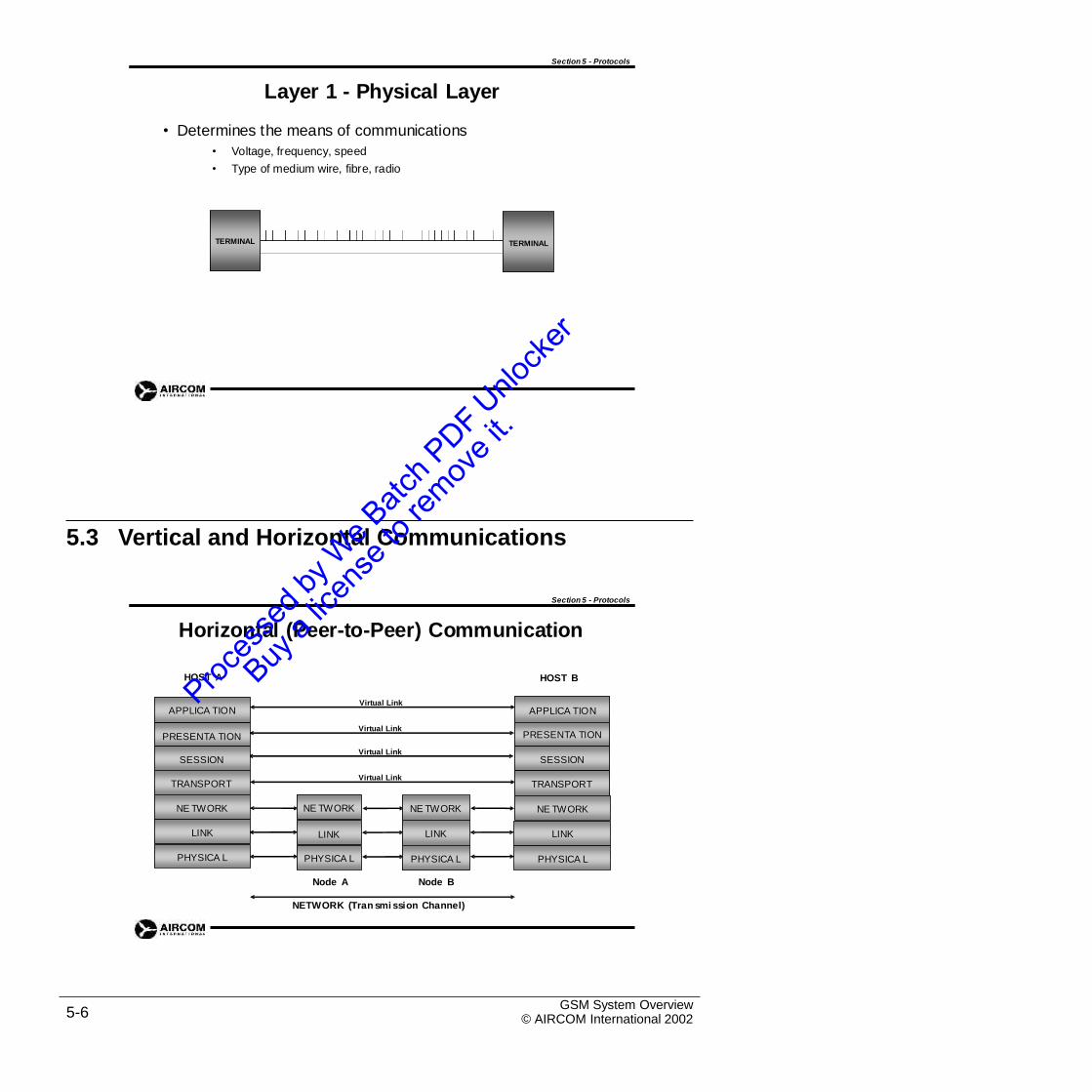
Section 5 - Protocols
Layer 1 - Physical Layer
• Determines the means of communications
•
•
Voltage, frequency, speed
Type of medium wire, fibre, radio
5.3 Vertical and Horizontal Communications
Section 5 - Protocols
Horizontal (Peer-to-Peer) Communication
HOST A HOST B
Virtual Link
Virtual Link
Virtual Link
Virtual Link
Node A Node B
NETWORK (Tran smi ssion Channel)
GSM System Overview© AIRCOM International 20025-6
NE TWORK
LINK
PHYSICA L
NE TWORK
LINK
PHYSICA L
APPLICA TION
PRESENTA TION
SESSION
TRANSPORT
NE TWORK
LINK
PHYSICA L
APPLICA TION
PRESENTA TION
SESSION
TRANSPORT
NE TWORK
LINK
PHYSICA L
TERMINALTERMINAL
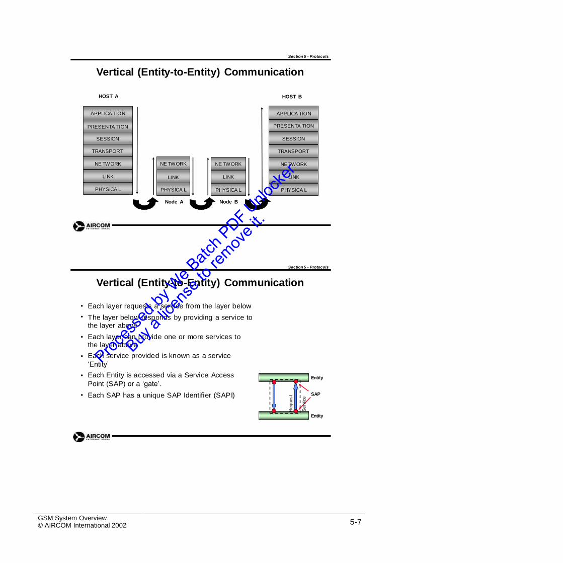
Section 5 - Protocols
Vertical (Entity-to-Entity) Communication
HOST A HOST B
Node A Node B
Section 5 - Protocols
Vertical (Entity-to-Entity) Communication
•
•
Each layer requests a service from the layer below
The layer below responds by providing a service to the layer above
Each layer can provide one or more services to the layer above
Each service provided is known as a service
‘Entity’
Each Entity is accessed via a Service Access
Point (SAP) or a ‘gate’.
Each SAP has a unique SAP Identifier (SAPI)
•
•
• Entity
• SAP
Entity
GSM System Overview© AIRCOM International 2002 5-7
Req
ues
t
Se
rvic
e
NE TWORK
LINK
PHYSICA L
NE TWORK
LINK
PHYSICA L
APPLICA TION
PRESENTA TION
SESSION
TRANSPORT
NE TWORK
LINK
PHYSICA L
APPLICA TION
PRESENTA TION
SESSION
TRANSPORT
NE TWORK
LINK
PHYSICA L
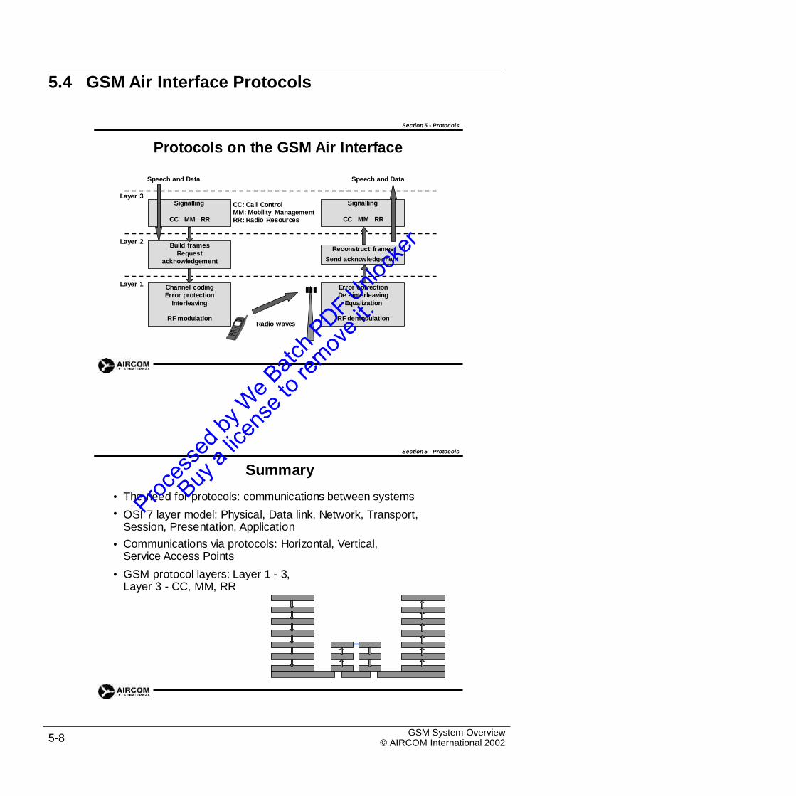
5.4 GSM Air Interface Protocols
Section 5 - Protocols
Protocols on the GSM Air Interface
Speech and Data Speech and Data
Layer 3
CC: Call ControlMM: Mobility ManagementRR: Radio Resources
Layer 2
Send acknowledgement
Layer 1
Radio waves
Section 5 - Protocols
Summary
The need for protocols: communications between systems
OSI 7 layer model: Physical, Data link, Network, Transport, Session, Presentation, Application
Communications via protocols: Horizontal, Vertical, Service Access Points
GSM protocol layers: Layer 1 - 3, Layer 3 - CC, MM, RR
•
•
•
•
GSM System Overview© AIRCOM International 20025-8
Error correction
De - interleaving
Equalization
RF demodulation
Channel coding
Error protection
Interleaving
RF modulation
Reconstruct framesBuild frames
Request
acknowledgement
Signalling
CC MM RR
Signalling
CC MM RR
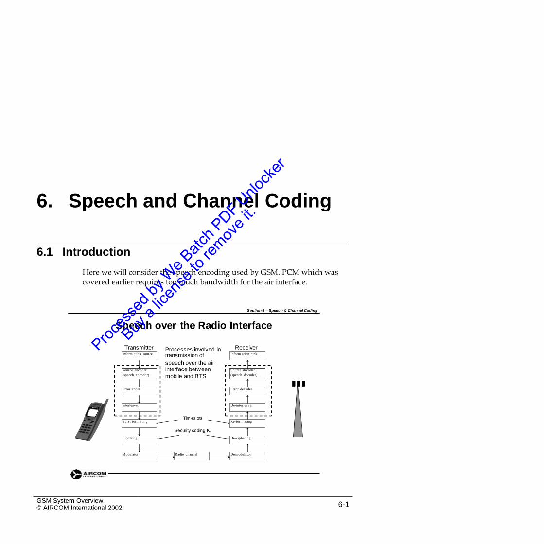
6. Speech and Channel Coding
6.1 Introduction
Here we will consider the speech encoding used by GSM. PCM which was covered earlier requires too much bandwidth for the air interface.
Section 6 – Speech & Channel Coding
Speech over the Radio Interface
Transmitter ReceiverProcesses involved in
GSM System Overview© AIRCOM International 2002 6-1
Inform ation source transmission of Inform ation sink
speech over the airinterface between
mobile and BTSSource encoder
(speech encoder)
Source decoder
(speech decoder)
Error coder Error decoder
Interleaver De-interleaver
Tim eslotsBurst form ating Re-form ating
Security coding Kc
Ciphering De-ciphering
Modulator Radio channel Dem odulator
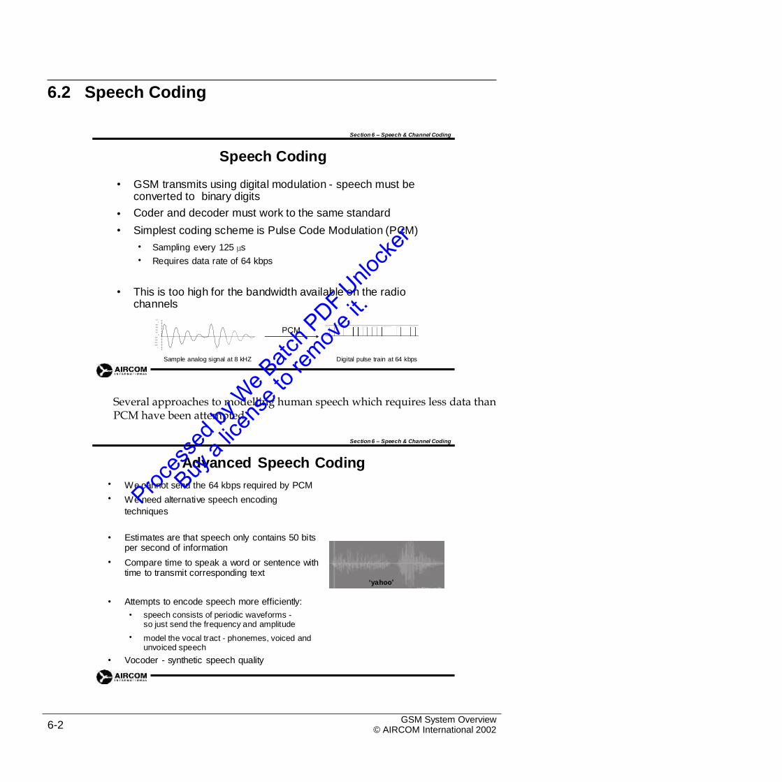
6.2 Speech Coding
Section 6 – Speech & Channel Coding
Speech Coding
• GSM transmits using digital modulation - speech must be converted to binary digits
Coder and decoder must work to the same standard
Simplest coding scheme is Pulse Code Modulation (PCM)
•
•
•
•
Sampling every 125 µs
Requires data rate of 64 kbps
• This is too high for the bandwidth available on the radio channels
1.2
1
0.8
0.6
0.4
0.2
0
-0.2
-0.4
-0.6
-0.8
-1
PCM
Sample analog signal at 8 kHZ Digital pulse train at 64 kbps
Several approaches to modelling human speech which requires less data thanPCM have been attempted.
Section 6 – Speech & Channel Coding
Advanced Speech Coding
We cannot send the 64 kbps required by PCM
We need alternative speech encoding
techniques
•
•
• Estimates are that speech only contains 50 bits per second of information
Compare time to speak a word or sentence with time to transmit corresponding text
•
‘yahoo’
• Attempts to encode speech more efficiently:
• speech consists of periodic waveforms -so just send the frequency and amplitude
model the vocal tract - phonemes, voiced and unvoiced speech
•
• Vocoder - synthetic speech quality
GSM System Overview© AIRCOM International 20026-2
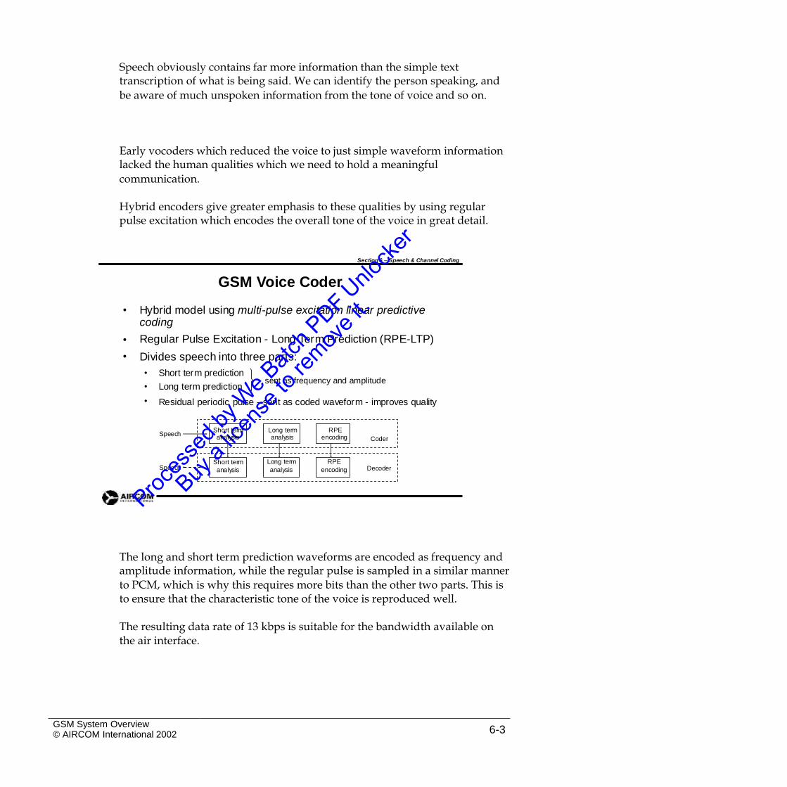
Speech obviously contains far more information than the simple texttranscription of what is being said. We can identify the person speaking, and
be aware of much unspoken information from the tone of voice and so on.
Early vocoders which reduced the voice to just simple waveform informationlacked the human qualities which we need to hold a meaningful
communication.
Hybrid encoders give greater emphasis to these qualities by using regularpulse excitation which encodes the overall tone of the voice in great detail.
Section 6 – Speech & Channel Coding
GSM Voice Coder
• Hybrid model using multi-pulse excitation linear predictive coding
Regular Pulse Excitation - Long Term Prediction (RPE-LTP)
Divides speech into three parts:
•
•
•
•
•
Short term prediction
Long term predictionsent as frequency and amplitude
Residual periodic pulse - sent as coded waveform - improves quality
Speech
Speech
The long and short term prediction waveforms are encoded as frequency andamplitude information, while the regular pulse is sampled in a similar manner
to PCM, which is why this requires more bits than the other two parts. This is to ensure that the characteristic tone of the voice is reproduced well.
The resulting data rate of 13 kbps is suitable for the bandwidth available onthe air interface.
GSM System Overview© AIRCOM International 2002 6-3
Short term
analysis
Long term RPE
analysis encoding Decoder
Short term Long term RPEanalysis analysis encoding Coder
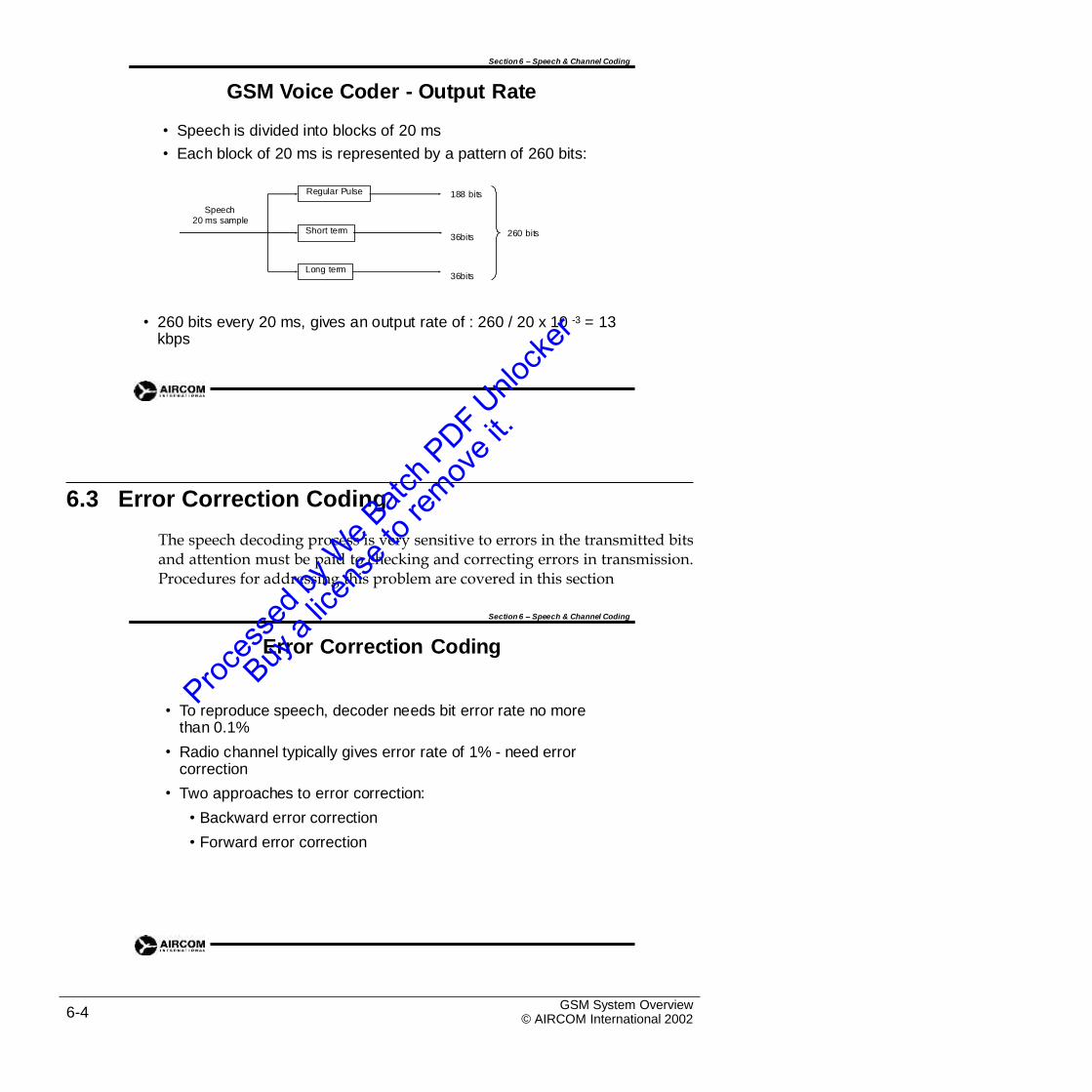
Section 6 – Speech & Channel Coding
GSM Voice Coder - Output Rate
• Speech is divided into blocks of 20 ms
• Each block of 20 ms is represented by a pattern of 260 bits:
188 bits
Speech20 ms sample
260 bits36bits
36bits
• 260 bits every 20 ms, gives an output rate of : 260 / 20 x 10 -3 = 13 kbps
6.3 Error Correction Coding
The speech decoding process is very sensitive to errors in the transmitted bitsand attention must be paid to checking and correcting errors in transmission.Procedures for addressing this problem are covered in this section
Section 6 – Speech & Channel Coding
Error Correction Coding
• To reproduce speech, decoder needs bit error rate no more than 0.1%
Radio channel typically gives error rate of 1% - need error correction
Two approaches to error correction:
• Backward error correction
• Forward error correction
•
•
GSM System Overview© AIRCOM International 20026-4
Long term
Short term
Regular Pulse
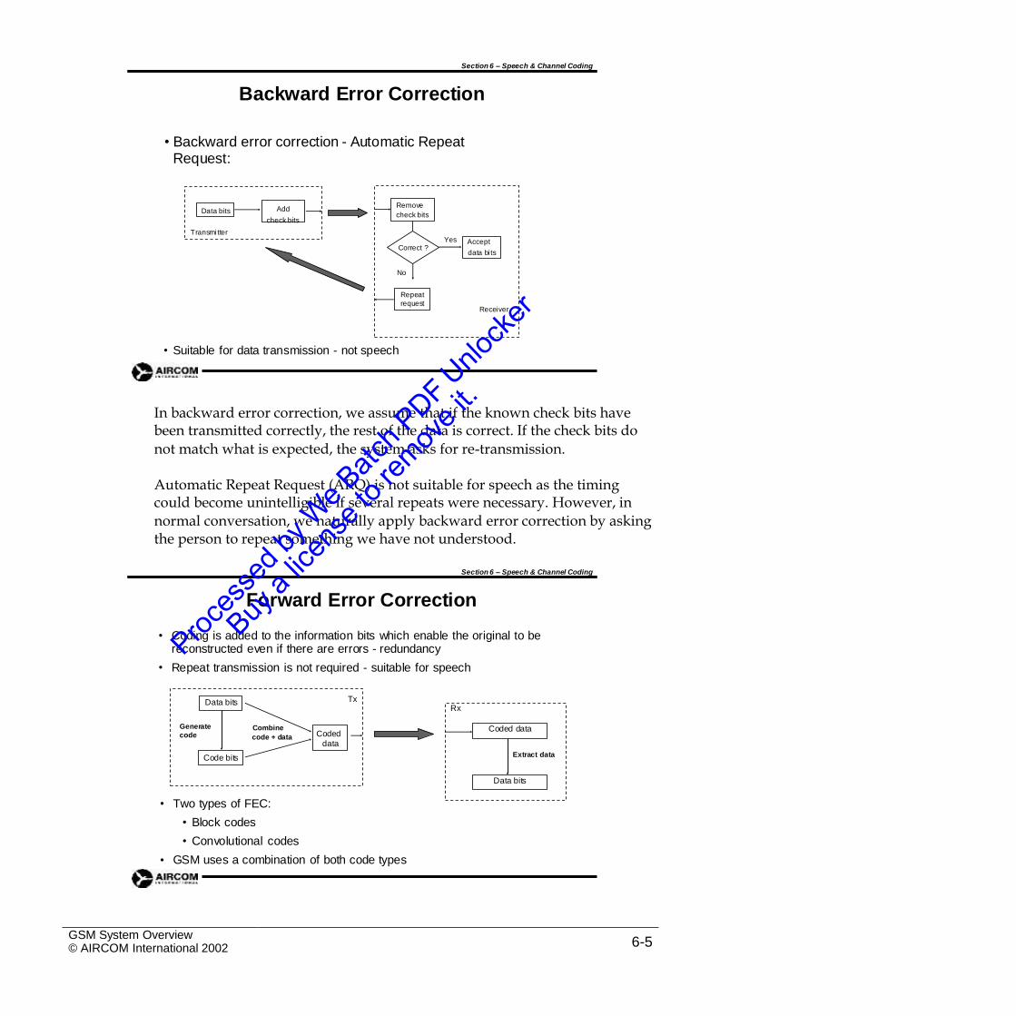
Section 6 – Speech & Channel Coding
Backward Error Correction
• Backward error correction - Automatic RepeatRequest:
Correct ?
Receiver
• Suitable for data transmission - not speech
In backward error correction, we assume that if the known check bits havebeen transmitted correctly, the rest of the data is correct. If the check bits do
not match what is expected, the system asks for re-transmission.
Automatic Repeat Request (ARQ) is not suitable for speech as the timingcould become unintelligible if several repeats were necessary. However, in
normal conversation, we naturally apply backward error correction by asking the person to repeat something we have not understood.
Section 6 – Speech & Channel Coding
Forward Error Correction
• Coding is added to the information bits which enable the original to be reconstructed even if there are errors - redundancy
Repeat transmission is not required - suitable for speech•
• Two types of FEC:
• Block codes
• Convolutional codes
GSM uses a combination of both code types•
GSM System Overview© AIRCOM International 2002 6-5
data
Rx
Coded data
Extract data
Data bits
Data bits Tx
Generate Combinecode code + data Coded
Code bits
data bi ts
check bits
Remove
Yes Accept
No
Repeat
request
Data bits Add
check bits
Transmi tter
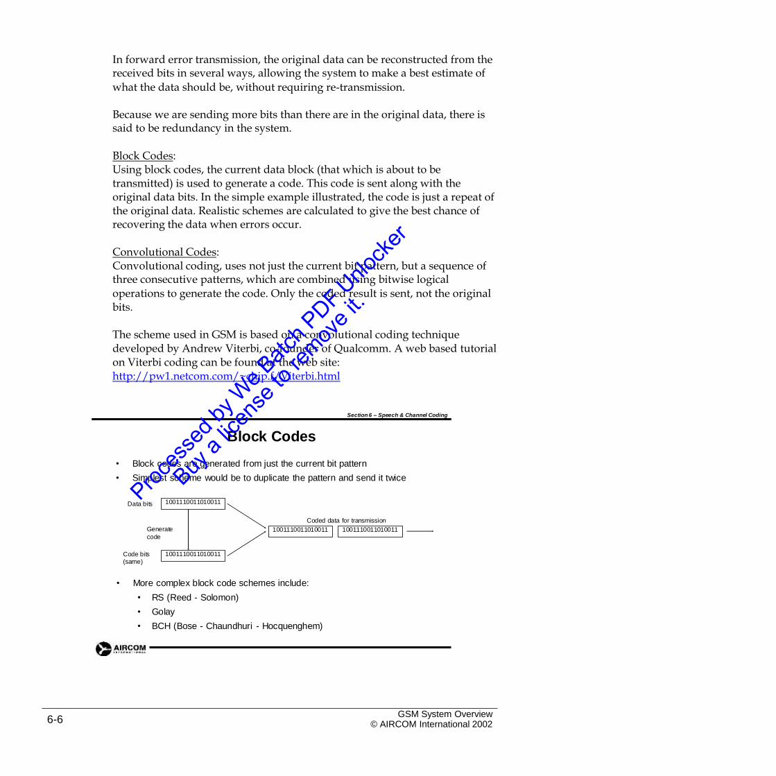
In forward error transmission, the original data can be reconstructed from thereceived bits in several ways, allowing the system to make a best estimate of
what the data should be, without requiring re-transmission.
Because we are sending more bits than there are in the original data, there issaid to be redundancy in the system.
Block Codes:Using block codes, the current data block (that which is about to betransmitted) is used to generate a code. This code is sent along with the original data bits. In the simple example illustrated, the code is just a repeat of the original data. Realistic schemes are calculated to give the best chance of recovering the data when errors occur.
Convolutional Codes:Convolutional coding, uses not just the current bit pattern, but a sequence ofthree consecutive patterns, which are combined using bitwise logical
operations to generate the code. Only the coded result is sent, not the original bits.
The scheme used in GSM is based on a convolutional coding techniquedeveloped by Andrew Viterbi, co-founder of Qualcomm. A web based tutorial on Viterbi coding can be found at the web site: http://pw1.netcom.com/~chip.f/Viterbi.html
Section 6 – Speech & Channel Coding
Block Codes
• Block codes are generated from just the current bit pattern
• Simplest scheme would be to duplicate the pattern and send it twice
Data bits
Coded data for transmission
Generate
code
Code bits(same)
• More complex block code schemes include:
•
•
•
RS (Reed - Solomon)
Golay
BCH (Bose - Chaundhuri - Hocquenghem)
GSM System Overview© AIRCOM International 20026-6
1001110011010011 1001110011010011
1001110011010011
1001110011010011
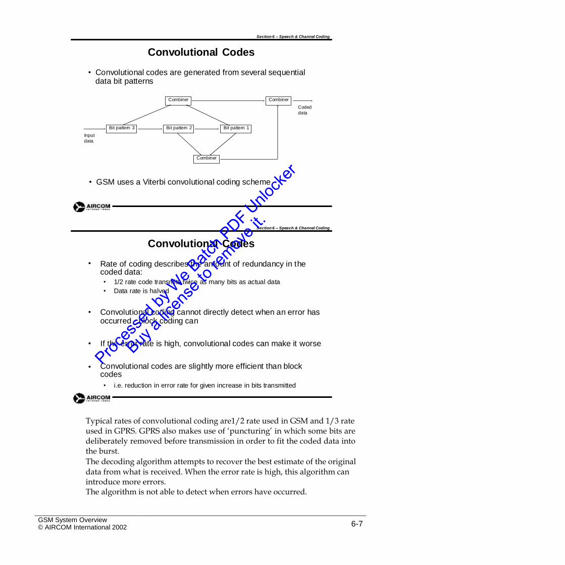
Section 6 – Speech & Channel Coding
Convolutional Codes
• Convolutional codes are generated from several sequential data bit patterns
Coded
data
Input
data
• GSM uses a Viterbi convolutional coding scheme
Section 6 – Speech & Channel Coding
Convolutional Codes
Rate of coding describes the amount of redundancy in the coded data:
•
•
•
1/2 rate code transmits twice as many bits as actual data
Data rate is halved
• Convolutional coding cannot directly detect when an error has occurred - block coding can
• If the error rate is high, convolutional codes can make it worse
• Convolutional codes are slightly more efficient than block codes
• i.e. reduction in error rate for given increase in bits transmitted
Typical rates of convolutional coding are1/2 rate used in GSM and 1/3 rateused in GPRS. GPRS also makes use of ‘puncturing’ in which some bits aredeliberately removed before transmission in order to fit the coded data intothe burst.
The decoding algorithm attempts to recover the best estimate of the original
data from what is received. When the error rate is high, this algorithm can introduce more errors.The algorithm is not able to detect when errors have occurred.
GSM System Overview© AIRCOM International 2002 6-7
Combiner
Bit pattern 1Bit pattern 2Bit pattern 3
CombinerCombiner
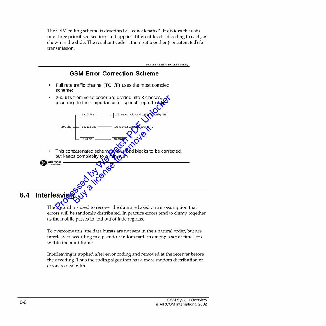
The GSM coding scheme is described as ‘concatenated’. It divides the datainto three prioritised sections and applies different levels of coding to each, as shown in the slide. The resultant code is then put together (concatenated) for transmission.
Section 6 – Speech & Channel Coding
GSM Error Correction Scheme
• Full rate traffic channel (TCH/F) uses the most complex scheme:
260 bits from voice coder are divided into 3 classes, according to their importance for speech reproduction:
•
• This concatenated scheme allows bad blocks to be corrected, but keeps complexity to a minimum
6.4 Interleaving
The algorithms used to recover the data are based on an assumption that errors will be randomly distributed. In practice errors tend to clump together as the mobile passes in and out of fade regions.
To overcome this, the data bursts are not sent in their natural order, but areinterleaved according to a pseudo-random pattern among a set of timeslots
within the multiframe.
Interleaving is applied after error coding and removed at the receiver beforethe decoding. Thus the coding algorithm has a more random distribution of
errors to deal with.
GSM System Overview© AIRCOM International 20026-8
no coding2: 78 bits
1/2 rate convolutional coding1b: 132 bits260 bits
1/2 rate convolutional coding + 3 parity bits1a: 50 bits
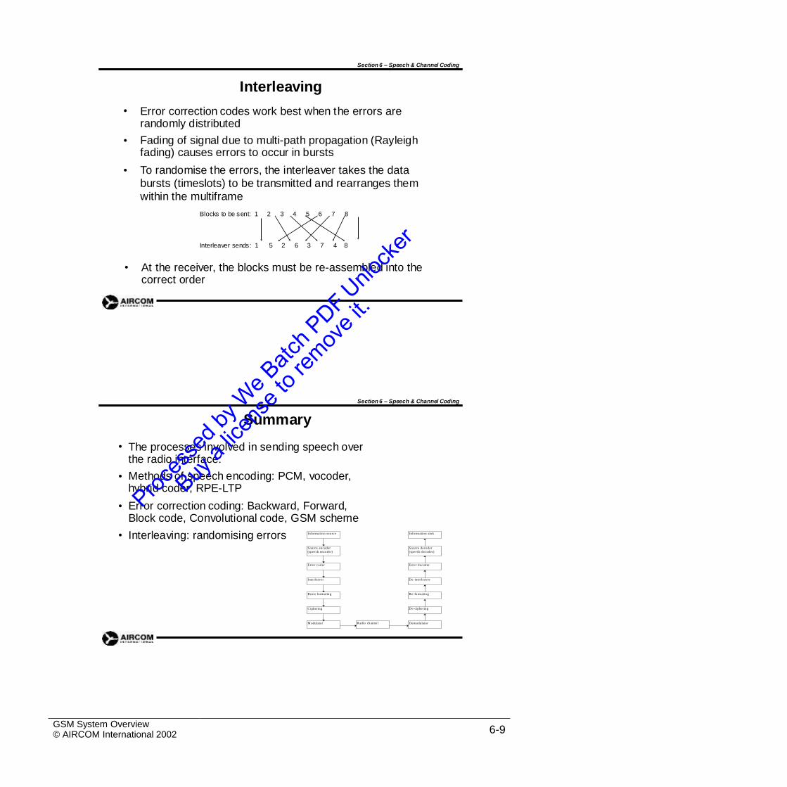
Section 6 – Speech & Channel Coding
Interleaving
Error correction codes work best when the errors are randomly distributed
Fading of signal due to multi-path propagation (Rayleigh fading) causes errors to occur in bursts
To randomise the errors, the interleaver takes the data bursts (timeslots) to be transmitted and rearranges them within the multiframe
•
•
•
Blocks to be sent: 1 2 3 4 5 6 7 8
Interleaver sends: 1 5 2 6 3 7 4 8
• At the receiver, the blocks must be re-assembled into the correct order
Section 6 – Speech & Channel Coding
Summary
The processes involved in sending speech over the radio interface:
Methods of speech encoding: PCM, vocoder, hybrid coder, RPE-LTP
Error correction coding: Backward, Forward, Block code, Convolutional code, GSM scheme
•
•
•
• Interleaving: randomising errors
GSM System Overview© AIRCOM International 2002 6-9
Information source Information sink
Source encoder
(speech encoder)
Source decoder
(speech decoder)
Erro r coder Erro r decoder
Interleaver De-interleaver
B urst formating R e-formating
C iphering De-ciphering
M odulator R adio channel Demodulator

Intentional Blank Page
GSM System Overview© AIRCOM International 20026-10
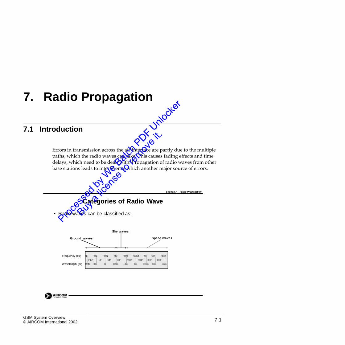
7. Radio Propagation
7.1 Introduction
Errors in transmission across the air interface are partly due to the multiplepaths, which the radio waves can take. This causes fading effects and time delays, which need to be dealt with. Propagation of radio waves from other base stations leads to interference which another major source of errors.
Section 7 – Radio Propagation
Categories of Radio Wave
• Radio waves can be classified as:
Sky waves
Space wavesGround waves
Frequency (Hz)
Wavelength (m)
GSM System Overview© AIRCOM International 2002 7-1
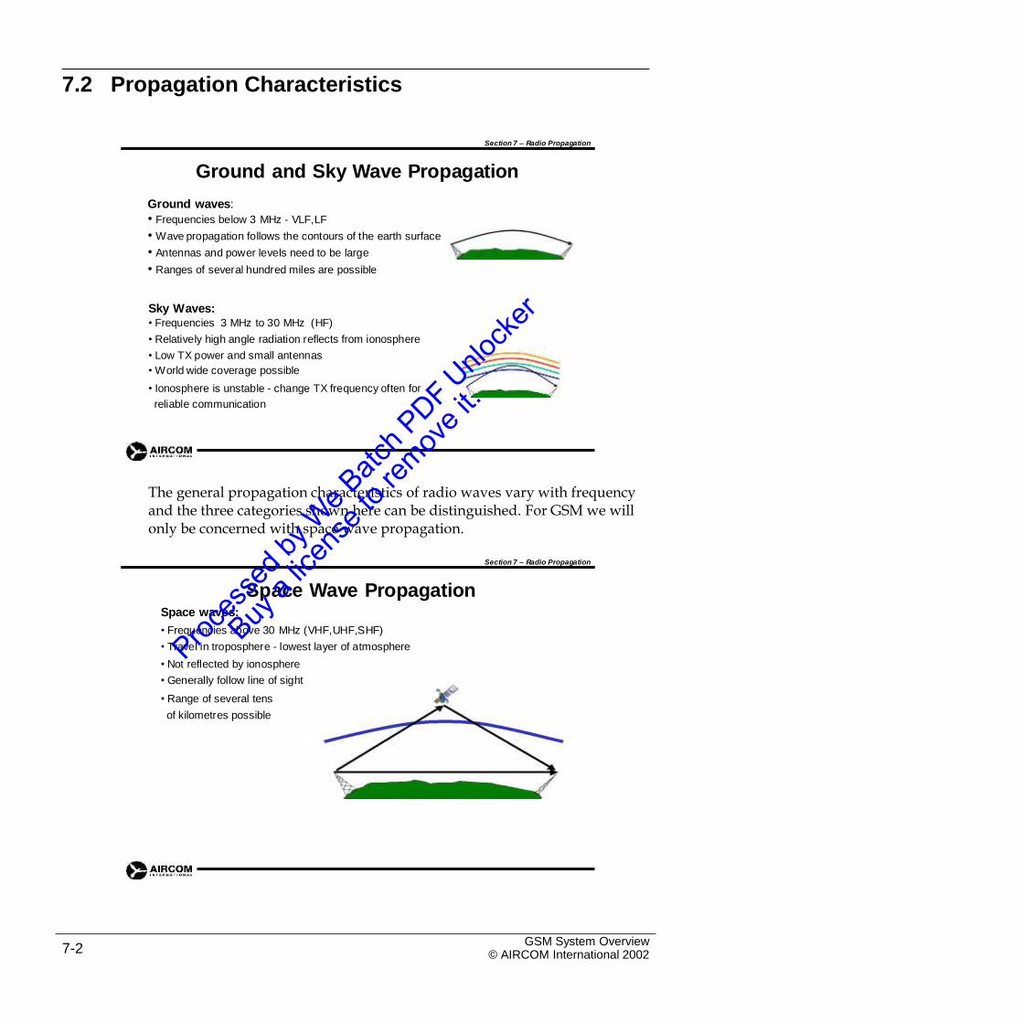
7.2 Propagation Characteristics
Section 7 – Radio Propagation
Ground and Sky Wave Propagation
Ground waves:
• Frequencies below 3 MHz - VLF,LF
• Wave propagation follows the contours of the earth surface
• Antennas and power levels need to be large
• Ranges of several hundred miles are possible
Sky Waves:• Frequencies 3 MHz to 30 MHz (HF)
• Relatively high angle radiation reflects from ionosphere
• Low TX power and small antennas
• World wide coverage possible
• Ionosphere is unstable - change TX frequency often for
reliable communication
The general propagation characteristics of radio waves vary with frequencyand the three categories shown here can be distinguished. For GSM we will only be concerned with space wave propagation.
Section 7 – Radio Propagation
Space Wave PropagationSpace waves:
• Frequencies above 30 MHz (VHF,UHF,SHF)
• Travel in troposphere - lowest layer of atmosphere
• Not reflected by ionosphere
• Generally follow line of sight
• Range of several tens
of kilometres possible
GSM System Overview© AIRCOM International 20027-2
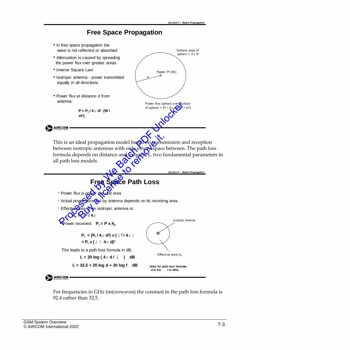
Section 7 – Radio Propagation
Free Space Propagation
• In free space propagation the
wave is not reflected or absorbed
• Attenuation is caused by spreading
the power flux over greater areas
• Inverse Square Law
• Isotropic antenna - power transmitted
equally in all directions
Surface area of
sphere = 4πd2
Power Pt (W)
d
• Power flux at distance d from
antenna:Power flux spread over surface
of sphere = Pt / 4πd2 (W / m2)P = Pt / 4πd2 (W /
m2)
This is an ideal propagation model based on transmission and receptionbetween isotropic antennas with only empty space between. The path loss
formula depends on distance and frequency, two fundamental parameters in all path loss models.
Section 7 – Radio Propagation
Free Space Path Loss
• Power flux is power per unit area
• Actual power received by antenna depends on its receiving area
• Effective area of an isotropic antenna is:
Ae = λ2 / 4πIsotropic antenna
• Power received: Pr = P x Ae
Pr = (Pt / 4πd2) x (λ2 / 4π)
= Pt x (λ / 4πd)2
This leads to a path loss formula in dB:
L = 20 log ( 4πd / λ ) dB
L = 32.5 + 20 log d + 20 log f dB
Effecti ve area Ae
Units for path loss formula:
d in km f in MHz
For frequencies in GHz (microwaves) the constant in the path loss formula is92.4 rather than 32.5.
GSM System Overview© AIRCOM International 2002 7-3
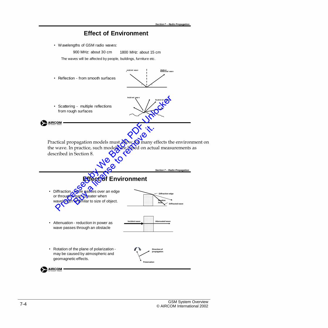
Section 7 – Radio Propagation
Effect of Environment
• Wavelengths of GSM radio waves:
900 MHz: about 30 cm 1800 MHz: about 15 cm
The waves will be affected by people, buildings, furniture etc.
I Reflected wave
• Reflection - from smooth surfaces
Incid ent wav e
Scatter ed ene rg y
• Scattering - multiple reflections
from rough surfaces
Practical propagation models must allow for many effects the environment onthe wave. In practice, such models are based on actual measurements as
described in Section 8.
Section 7 – Radio Propagation
Effect of Environment
• Diffraction - wave passes over an edge
or through a gap. Greater when
wavelength is similar to size of object.
Diffraction edge
Diffracted wave
• Attenuation - reduction in power as
wave passes through an obstacle
• Rotation of the plane of polarization -
may be caused by atmospheric and
geomagnetic effects.
Direction of
propagation
Polarization
GSM System Overview© AIRCOM International 20027-4
Incident wave Attenuated wave
ShadowArea
ncident wave
α
Reflect
α
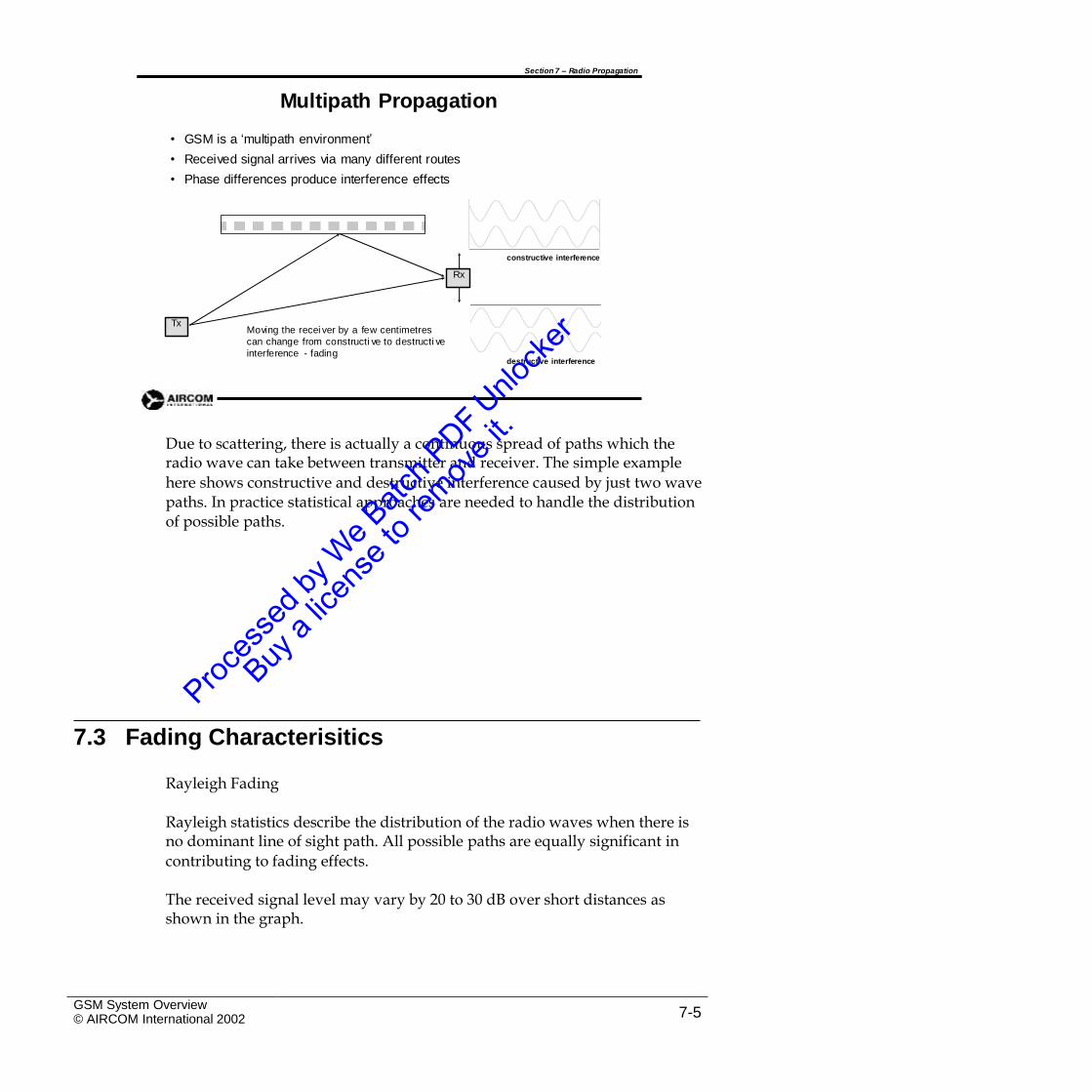
Section 7 – Radio Propagation
Multipath Propagation
•
•
•
GSM is a ‘multipath environment’
Received signal arrives via many different routes
Phase differences produce interference effects
constructive interference
Moving the recei ver by a few centimetres
can change from constructi ve to destructi ve
interference - fadingdestructive interference
Due to scattering, there is actually a continuous spread of paths which theradio wave can take between transmitter and receiver. The simple example
here shows constructive and destructive interference caused by just two wave paths. In practice statistical approaches are needed to handle the distribution of possible paths.
7.3 Fading Characterisitics
Rayleigh Fading
Rayleigh statistics describe the distribution of the radio waves when there isno dominant line of sight path. All possible paths are equally significant in
contributing to fading effects.
The received signal level may vary by 20 to 30 dB over short distances asshown in the graph.
GSM System Overview© AIRCOM International 2002 7-5
Tx
Rx
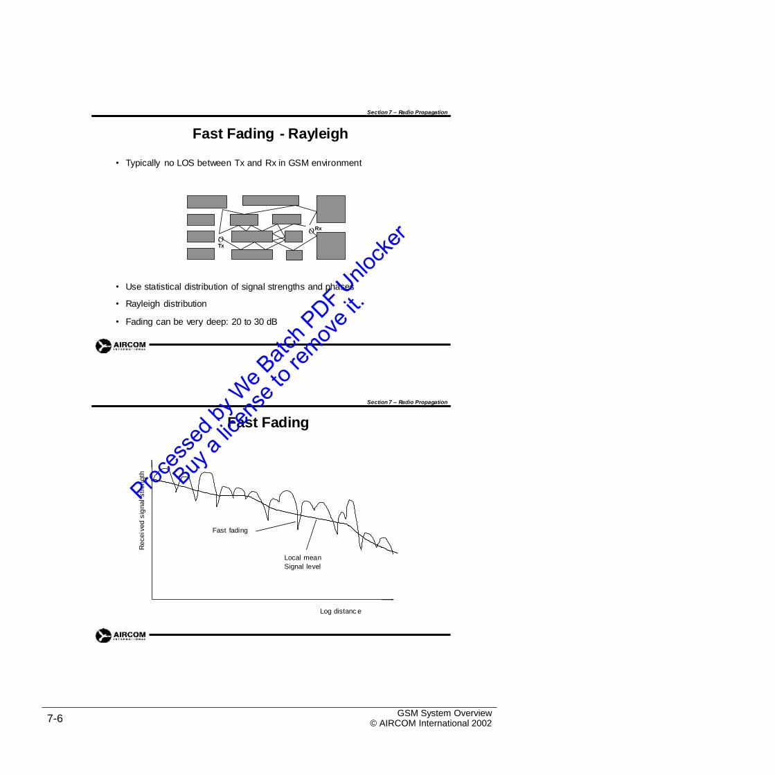
Section 7 – Radio Propagation
Fast Fading - Rayleigh
• Typically no LOS between Tx and Rx in GSM environment
O Rx
OTx
•
•
•
Use statistical distribution of signal strengths and phases
Rayleigh distribution
Fading can be very deep: 20 to 30 dB
Section 7 – Radio Propagation
Fast Fading
Log distanc e
GSM System Overview© AIRCOM International 20027-6
Receiv
ed
sig
nal
str
en
gth
Fast fading
Local mean
Signal level
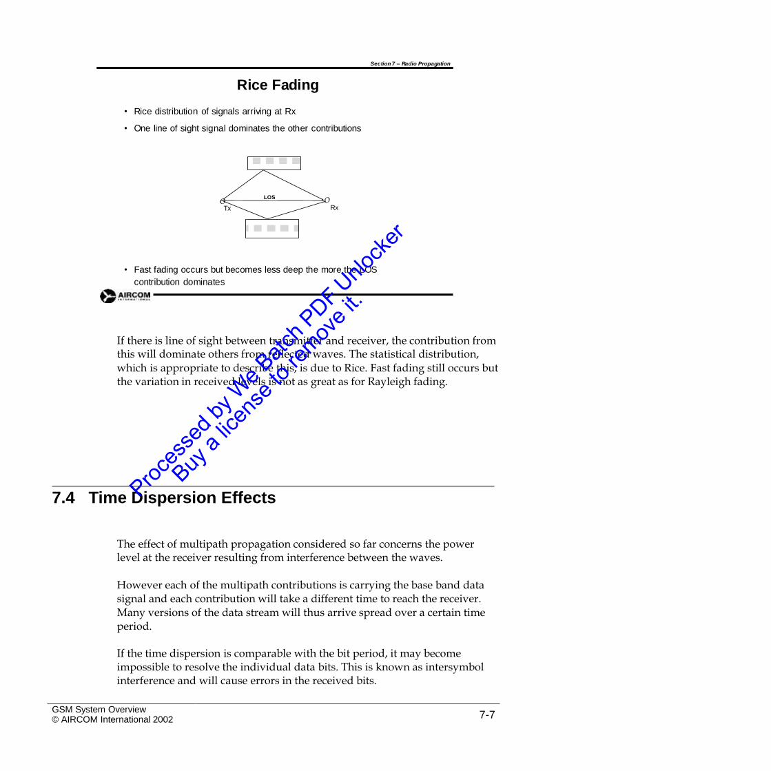
Section 7 – Radio Propagation
Rice Fading
•
•
Rice distribution of signals arriving at Rx
One line of sight signal dominates the other contributions
LOS ORx
OTx
• Fast fading occurs but becomes less deep the more the LOS
contribution dominates
If there is line of sight between transmitter and receiver, the contribution fromthis will dominate others from reflected waves. The statistical distribution,
which is appropriate to describe this, is due to Rice. Fast fading still occurs but the variation in received levels is not as great as for Rayleigh fading.
7.4 Time Dispersion Effects
The effect of multipath propagation considered so far concerns the powerlevel at the receiver resulting from interference between the waves.
However each of the multipath contributions is carrying the base band datasignal and each contribution will take a different time to reach the receiver. Many versions of the data stream will thus arrive spread over a certain time period.
If the time dispersion is comparable with the bit period, it may becomeimpossible to resolve the individual data bits. This is known as intersymbol interference and will cause errors in the received bits.
GSM System Overview© AIRCOM International 2002 7-7
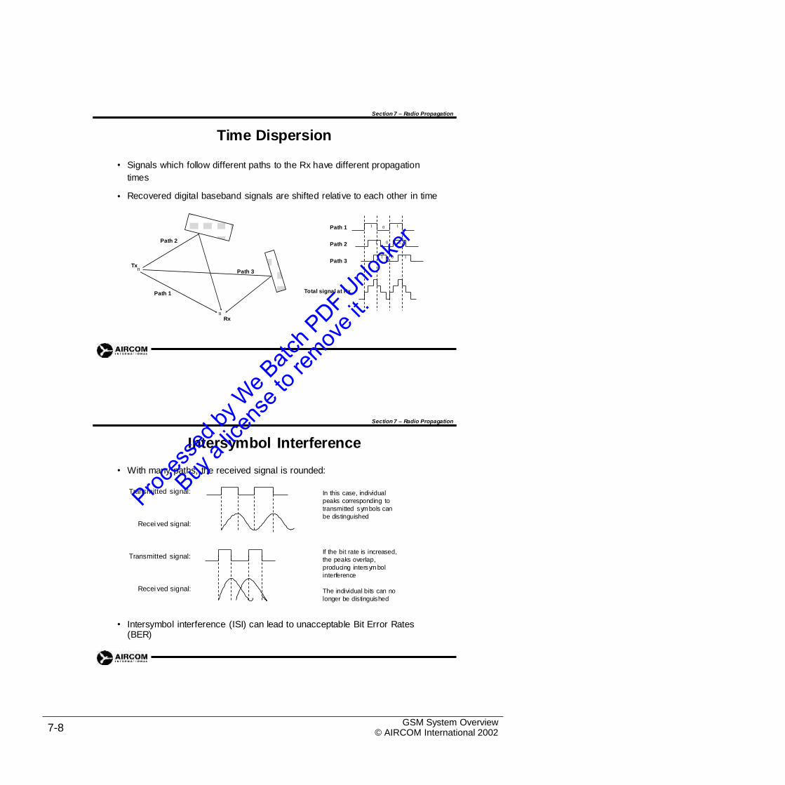
Section 7 – Radio Propagation
Time Dispersion
• Signals which follow different paths to the Rx have different propagation
times
Recovered digital baseband signals are shifted relative to each other in time•
Path 1
Path 2Path 2
Path 3Tx
nPath 3
Total signal at RxPath 1
nRx
Section 7 – Radio Propagation
Intersymbol Interference
• With many paths, the received signal is rounded:
Transmitted signal: In this case, individual
peaks corresponding to
transmitted symbols can
be distinguishedRecei ved signal:
If the bit rate is increased,
the peaks overlap,
producing intersym bol
interference
Transmitted signal:
Recei ved signal: The individual bits can no
longer be distinguished
• Intersymbol interference (ISI) can lead to unacceptable Bit Error Rates(BER)
GSM System Overview© AIRCOM International 20027-8
0 11
1 0 1
1 0 1
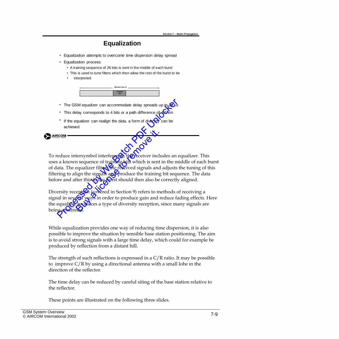
Section 7 – Radio Propagation
Equalization
•
•
Equalization attempts to overcome time dispersion delay spread
Equalization process:
• A training sequence of 26 bits is sent in the middle of each burst
• This is used to tune filters which then allow the rest of the burst to be
• interpreted
•
•
•
The GSM equalizer can accommodate delay spreads up to 16 µs
This delay corresponds to 4 bits or a path difference of 4.5 km
If the equalizer can realign the data, a form of diversity can be
achieved
To reduce intersymbol interference, the receiver includes an equalizer. Thisuses a known sequence of training bits which is sent in the middle of each burst of data. The equalizer filters the received signals and adjusts the tuning of this filtering to align the signals and produce the training bit sequence. The data before and after this in the burst should then also be correctly aligned.
Diversity reception (covered in Section 9) refers to methods of receiving asignal in several ways in order to produce gain and reduce fading effects. Here the equalizer produces a type of diversity reception, since many signals are being combined.
While equalization provides one way of reducing time dispersion, it is alsopossible to improve the situation by sensible base station positioning. The aim
is to avoid strong signals with a large time delay, which could for example be produced by reflection from a distant hill.
The strength of such reflections is expressed in a C/R ratio. It may be possibleto improve C/R by using a directional antenna with a small lobe in the direction of the reflector.
The time delay can be reduced by careful siting of the base station relative tothe reflector.
These points are illustrated on the following three slides.
GSM System Overview© AIRCOM International 2002 7-9
Norma l bur st
Training
bits
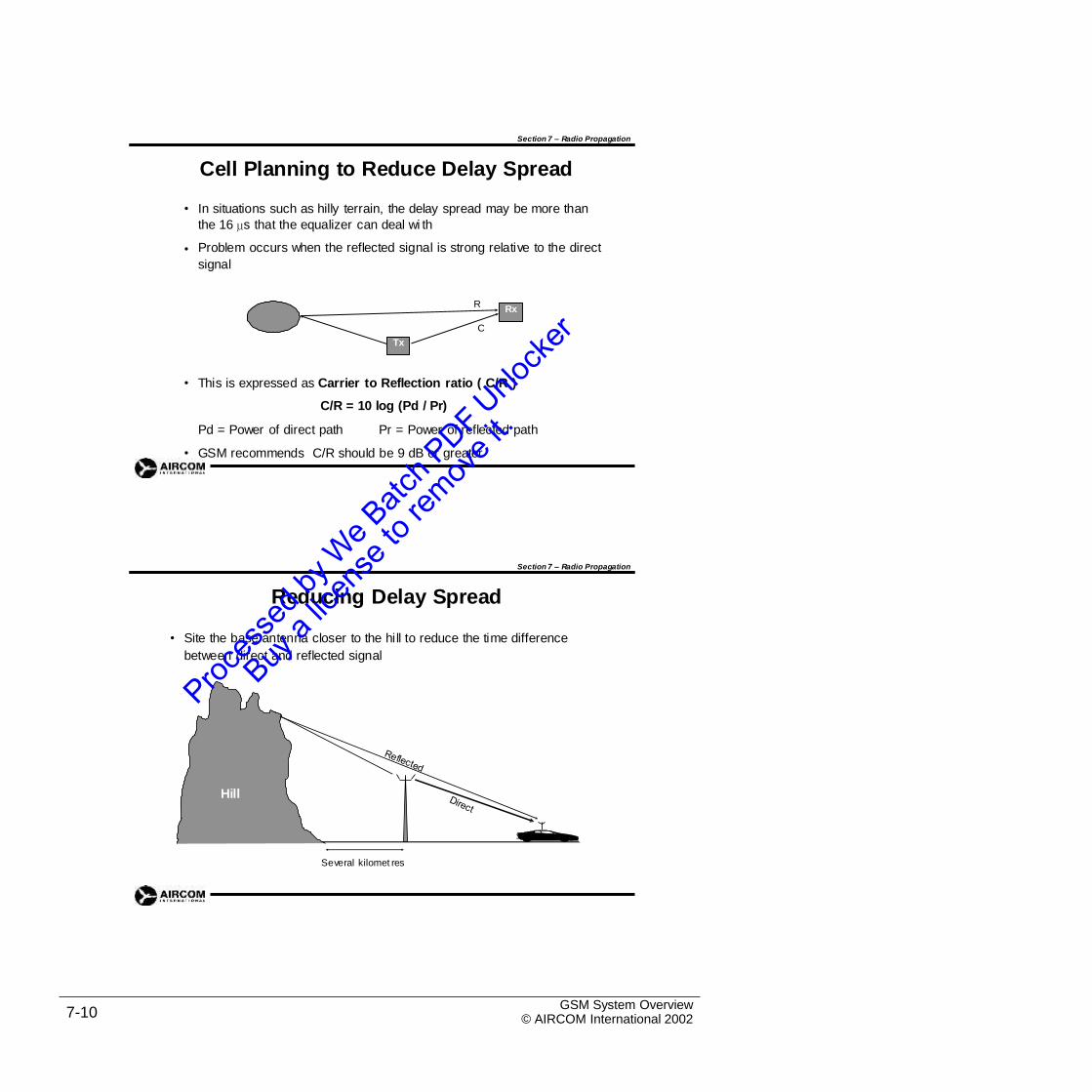
Section 7 – Radio Propagation
Cell Planning to Reduce Delay Spread
• In situations such as hilly terrain, the delay spread may be more than
the 16 µs that the equalizer can deal wi th
Problem occurs when the reflected signal is strong relative to the direct
signal
•
R
C
• This is expressed as Carrier to Reflection ratio ( C/R )
C/R = 10 log (Pd / Pr)
Pd = Power of direct path Pr = Power of reflected path
• GSM recommends C/R should be 9 dB or greater
Section 7 – Radio Propagation
Reducing Delay Spread
• Site the base antenna closer to the hill to reduce the time difference
between direct and reflected signal
Hill
Several kilomet res
GSM System Overview© AIRCOM International 20027-10
Tx
Rx
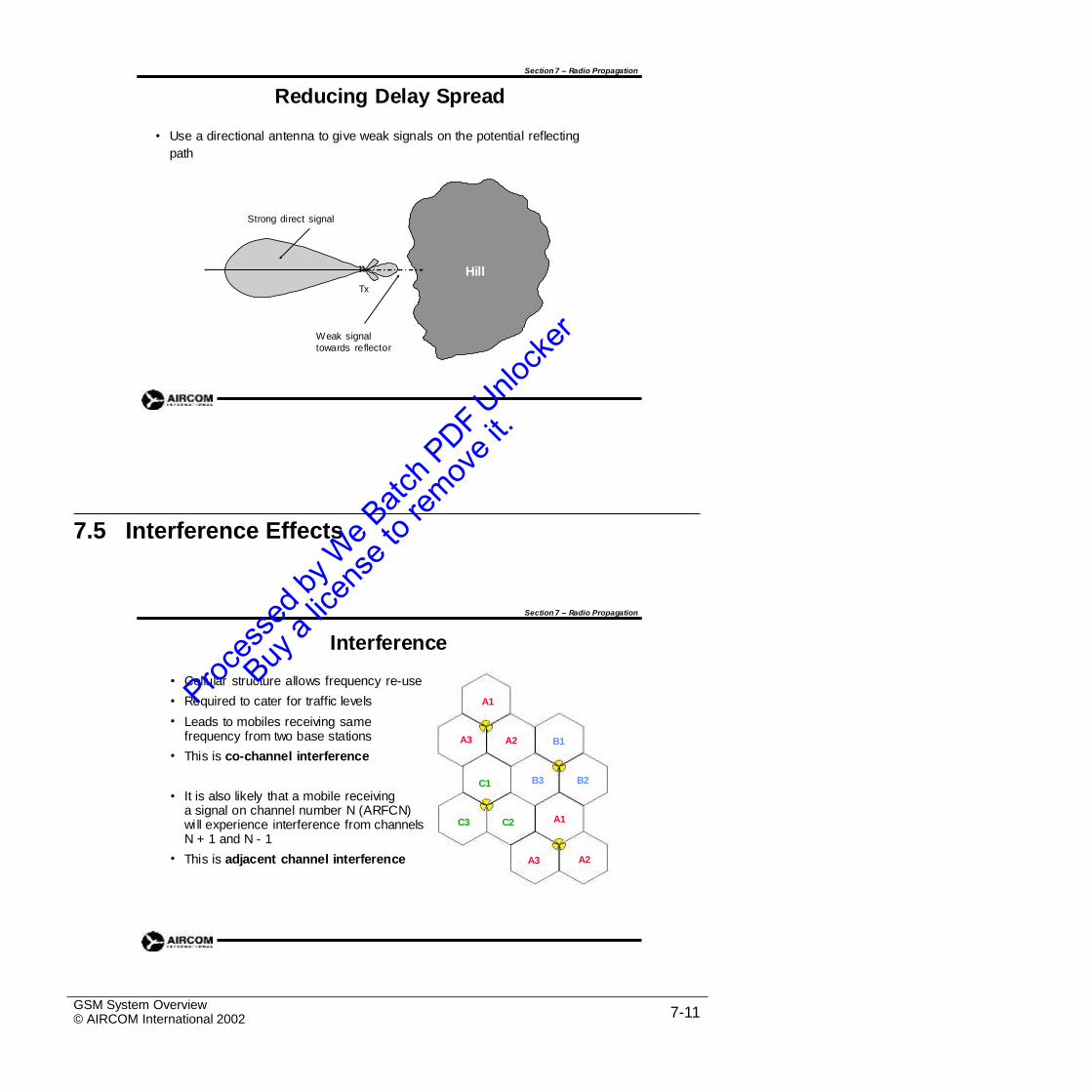
Section 7 – Radio Propagation
Reducing Delay Spread
• Use a directional antenna to give weak signals on the potential reflecting
path
Strong direct signal
n Hill
Tx
Weak signal
towards reflector
7.5 Interference Effects
Section 7 – Radio Propagation
Interference
•
•
•
Cellular structure allows frequency re-use
Required to cater for traffic levels
Leads to mobiles receiving same frequency from two base stations
This is co-channel interference
A1
A3 A2 B1
•
B3 B2C1
• It is also likely that a mobile receivinga signal on channel number N (ARFCN)will experience interference from channelsN + 1 and N - 1
This is adjacent channel interference
A1C3 C2
• A2A3
GSM System Overview© AIRCOM International 2002 7-11
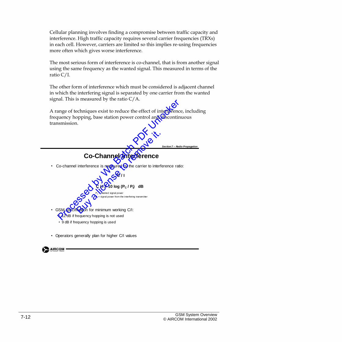
Cellular planning involves finding a compromise between traffic capacity andinterference. High traffic capacity requires several carrier frequencies (TRXs) in each cell. However, carriers are limited so this implies re-using frequencies more often which gives worse interference.
The most serious form of interference is co-channel, that is from another signalusing the same frequency as the wanted signal. This measured in terms of the
ratio C/I.
The other form of interference which must be considered is adjacent channelin which the interfering signal is separated by one carrier from the wanted signal. This is measured by the ratio C/A.
A range of techniques exist to reduce the effect of interference, includingfrequency hopping, base station power control and discontinuous transmission.
Section 7 – Radio Propagation
Co-Channel Interference
Co-channel interference is measured by the carrier to interference ratio:•
C / I
C / I = 10 log (PC / PI) dB
PC = wanted signal power
PI = signal power from the interfering transmi tter
• GSM specification for minimum working C/I:
• 12 dB if frequency hopping is not used
• 9 dB if frequency hopping is used
• Operators generally plan for higher C/I values
GSM System Overview© AIRCOM International 20027-12
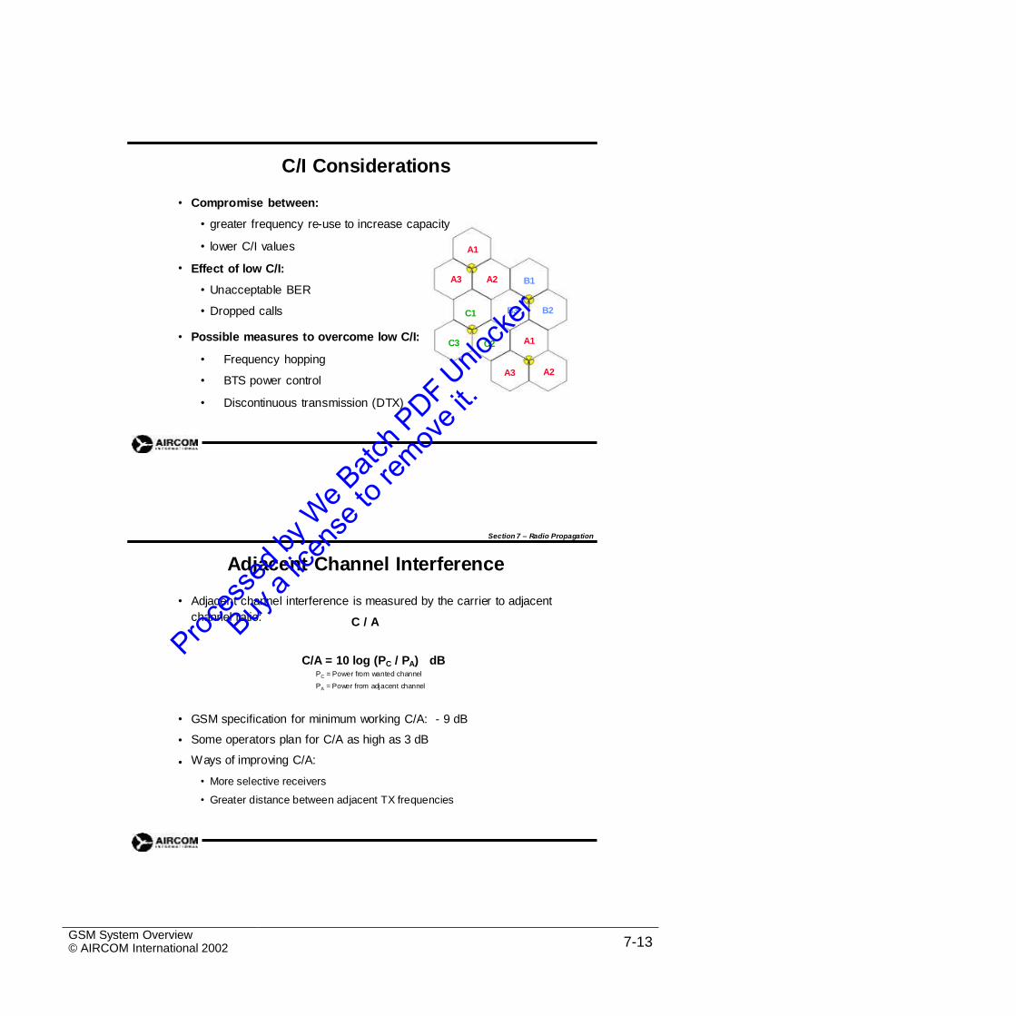
C/I Considerations
• Compromise between:
• greater frequency re-use to increase capacity
• lower C/I values
Effect of low C/I:
A1
•A3 A2 B1
• Unacceptable BER
• Dropped calls B3 B2C1
• Possible measures to overcome low C/I: A1C3 C2
•
•
•
Frequency hopping
BTS power control
Discontinuous transmission (DTX)
A2A3
Section 7 – Radio Propagation
Adjacent Channel Interference
• Adjacent channel interference is measured by the carrier to adjacent
channel ratio: C / A
C/A = 10 log (PC / PA) dBPC = Power from wanted channel
PA = Power from adjacent channel
•
•
•
GSM specification for minimum working C/A: - 9 dB
Some operators plan for C/A as high as 3 dB
Ways of improving C/A:
• More selective receivers
• Greater distance between adjacent TX frequencies
GSM System Overview© AIRCOM International 2002 7-13
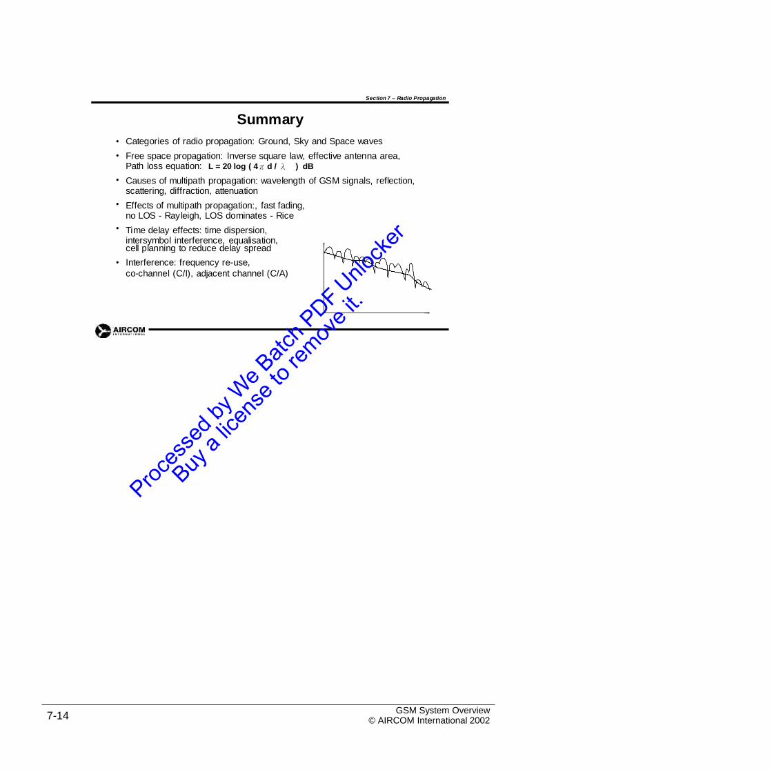
Section 7 – Radio Propagation
Summary
Categories of radio propagation: Ground, Sky and Space waves
Free space propagation: Inverse square law, effective antenna area, Path loss equation: L = 20 log ( 4πd / λ ) dB
Causes of multipath propagation: wavelength of GSM signals, reflection, scattering, diffraction, attenuation
Effects of multipath propagation:, fast fading, no LOS - Rayleigh, LOS dominates - Rice
Time delay effects: time dispersion, intersymbol interference, equalisation,
•
•
•
•
•
cell planning to reduce delay spread
Interference: frequency re-use,
co-channel (C/I), adjacent channel (C/A)
•
GSM System Overview© AIRCOM International 20027-14
Section 7 Self-Assessment Exercises
Exercise 7.1 - Free Space Path Loss
1. A 900 MHz antenna is transmitting a signal at 30 dBm
For reliable reception, a signal of at least -90 dBm is needed at the mobile.
Assuming only free space path loss, what radius of cell does this give?
2. Two rival operators have GSM networks in an area. One uses only GSM 900the other only DCS 1800.
equipment,
What does this tell you about the investment in equipment required by the operators togive equal coverage?
GSM System Overview© AIRCOM International 2002 7-15

Intentional Blank Page
GSM System Overview© AIRCOM International 20027-16
8. Cell Planning Principles
8.1 Introduction
In this overview course we look briefly at the principles of cell planning whichare covered in more depth in the AIRCOM courses G101 (Radio Planning
Fundamentals) and G103 (Advanced GSM Cell Planning). Toppics covered in this section include:
•
•
•
•
•
Coverage Prediction
Network Dimensioning
Traffic Capacity
Frequency Planning
Dual Band Systems
GSM System Overview© AIRCOM International 2002 8-1
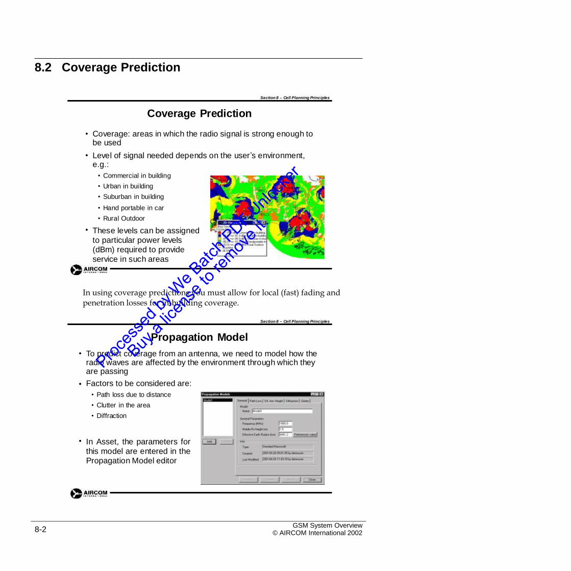
8.2 Coverage Prediction
Section 8 – Cell Planning Principles
Coverage Prediction
• Coverage: areas in which the radio signal is strong enough to be used
Level of signal needed depends on the user’s environment, e.g.:
• Commercial in building
• Urban in building
• Suburban in building
• Hand portable in car
• Rural Outdoor
These levels can be assigned to particular power levels (dBm) required to provide service in such areas
•
•
In using coverage predictions you must allow for local (fast) fading andpenetration losses for in-building coverage.
Section 8 – Cell Planning Principles
Propagation Model
To predict coverage from an antenna, we need to model how the radio waves are affected by the environment through which they are passing
Factors to be considered are:
• Path loss due to distance
• Clutter in the area
• Diffraction
•
•
• In Asset, the parameters forthis model are entered in thePropagation Model editor
GSM System Overview© AIRCOM International 20028-2
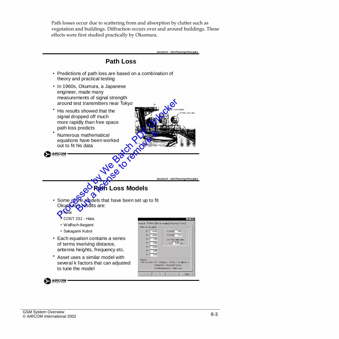
Path losses occur due to scattering from and absorption by clutter such asvegetation and buildings. Diffraction occurs over and around buildings. These effects were first studied practically by Okumura.
Section 8 – Cell Planning Principles
Path Loss
• Predictions of path loss are based on a combination of theory and practical testing
In 1960s, Okumura, a Japanese engineer, made many measurements of signal strength around test transmitters near Tokyo
His results showed that the signal dropped off much more rapidly than free space path loss predicts
Numerous mathematical equations have been worked out to fit his data
•
•
•
Section 8 – Cell Planning Principles
Path Loss Models
• Some of the models that have been set up to fitOkumura’s results are:
• Hata
• COST 231 - Hata
• Walfisch-Ikegami
• Sakagami Kuboi
Each equation contains a series of terms involving distance, antenna heights, frequency etc.
Asset uses a similar model with several k factors that can adjusted to tune the model
•
•
GSM System Overview© AIRCOM International 2002 8-3
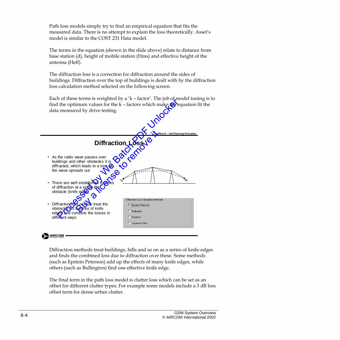
Path loss models simply try to find an empirical equation that fits themeasured data. There is no attempt to explain the loss theoretically. Asset’s
model is similar to the COST 231 Hata model.
The terms in the equation (shown in the slide above) relate to distance frombase station (d), height of mobile station (Hms) and effective height of the
antenna (Heff).
The diffraction loss is a correction for diffraction around the sides ofbuildings. Diffraction over the top of buildings is dealt with by the diffraction loss calculation method selected on the following screen.
Each of these terms is weighted by a ‘k – factor’. The job of model tuning is tofind the optimum values for the k – factors which make the equation fit the data measured by drive testing.
Section 8 – Cell Planning Principles
Diffraction Loss
• As the radio wave passes over buildings and other obstacles it is diffracted, which leads to a loss as the wave spreads out
RxTx
• There are well established theories of diffraction at a single flatobstacle (knife edge)
• Diffraction loss models treat the obstacles as a series of knife edges and combine the losses in different ways
Diffraction methods treat buildings, hills and so on as a series of knife-edgesand finds the combined loss due to diffraction over these. Some methods
(such as Epstein Peterson) add up the effects of many knife edges, while others (such as Bullington) find one effective knife edge.
The final term in the path loss model is clutter loss which can be set as anoffset for different clutter types. For example some models include a 3 dB loss
offset term for dense urban clutter.
GSM System Overview© AIRCOM International 20028-4
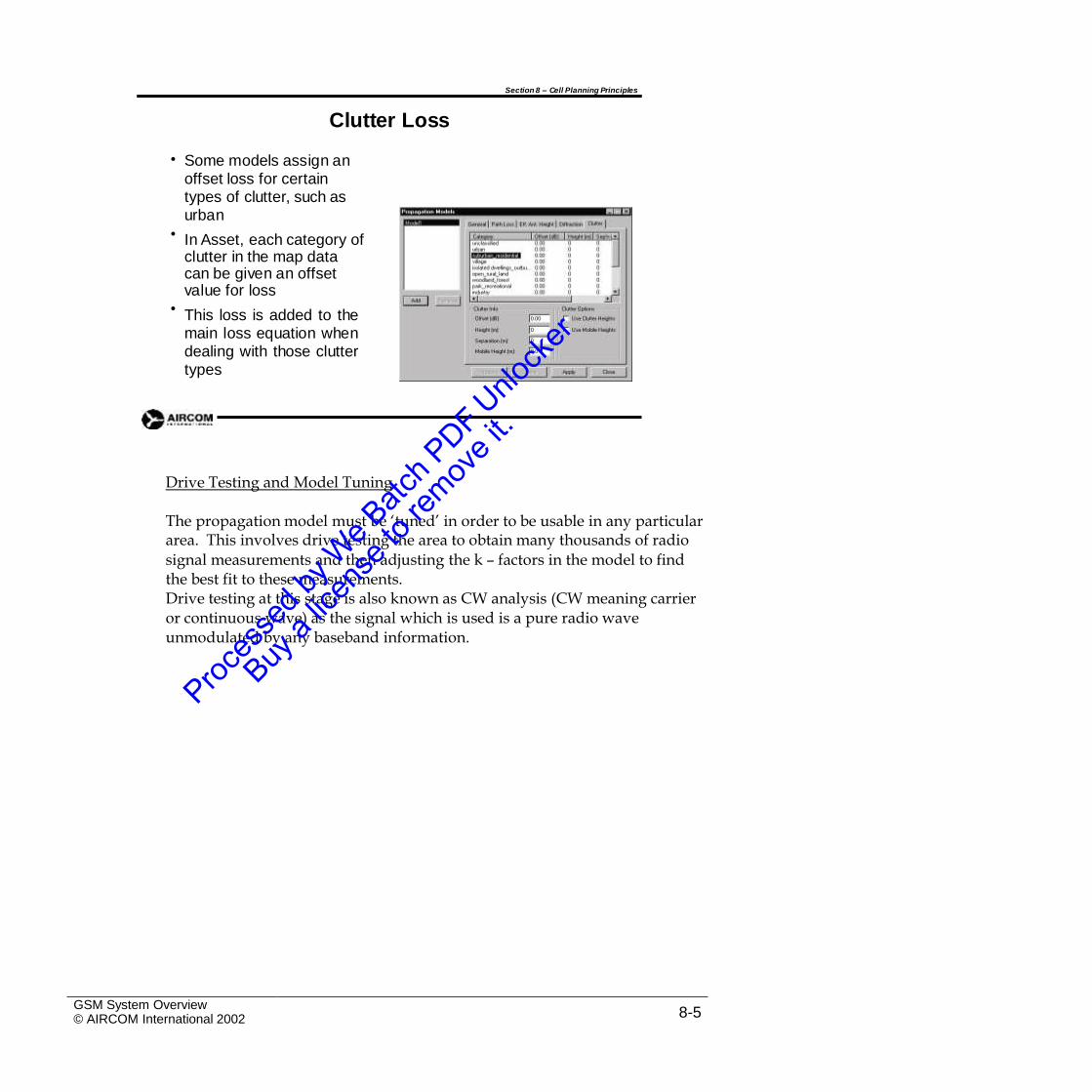
Section 8 – Cell Planning Principles
Clutter Loss
• Some models assign an offset loss for certain types of clutter, such as urban
In Asset, each category of clutter in the map datacan be given an offset value for loss
This loss is added to themain loss equation whendealing with those cluttertypes
•
•
Drive Testing and Model Tuning
The propagation model must be ‘tuned’ in order to be usable in any particulararea. This involves drive testing the area to obtain many thousands of radio
signal measurements and then adjusting the k – factors in the model to find the best fit to these measurements.Drive testing at this stage is also known as CW analysis (CW meaning carrier or continuous wave) as the signal which is used is a pure radio wave unmodulated by any baseband information.
GSM System Overview© AIRCOM International 2002 8-5
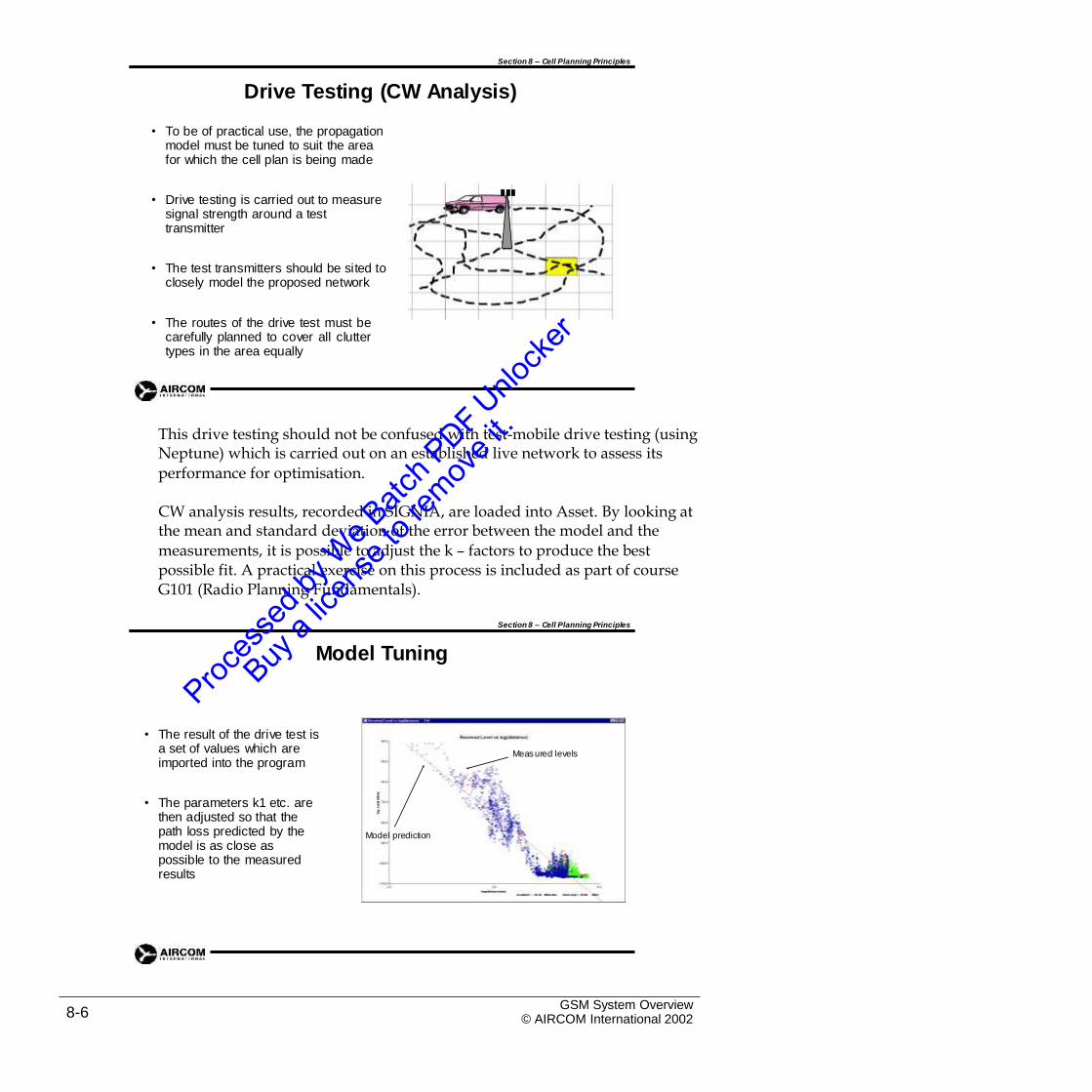
Section 8 – Cell Planning Principles
Drive Testing (CW Analysis)
• To be of practical use, the propagation model must be tuned to suit the area for which the cell plan is being made
• Drive testing is carried out to measure signal strength around a test transmitter
• The test transmitters should be sited to closely model the proposed network
• The routes of the drive test must becarefully planned to cover all cluttertypes in the area equally
This drive testing should not be confused with test-mobile drive testing (usingNeptune) which is carried out on an established live network to assess its
performance for optimisation.
CW analysis results, recorded in SIGNIA, are loaded into Asset. By looking atthe mean and standard deviation of the error between the model and the
measurements, it is possible to adjust the k – factors to produce the best possible fit. A practical exercise on this process is included as part of course G101 (Radio Planning Fundamentals).
Section 8 – Cell Planning Principles
Model Tuning
• The result of the drive test is a set of values which are imported into the program
Measured levels
• The parameters k1 etc. are then adjusted so that the path loss predicted by the model is as close as possible to the measured results
Model prediction
GSM System Overview© AIRCOM International 20028-6
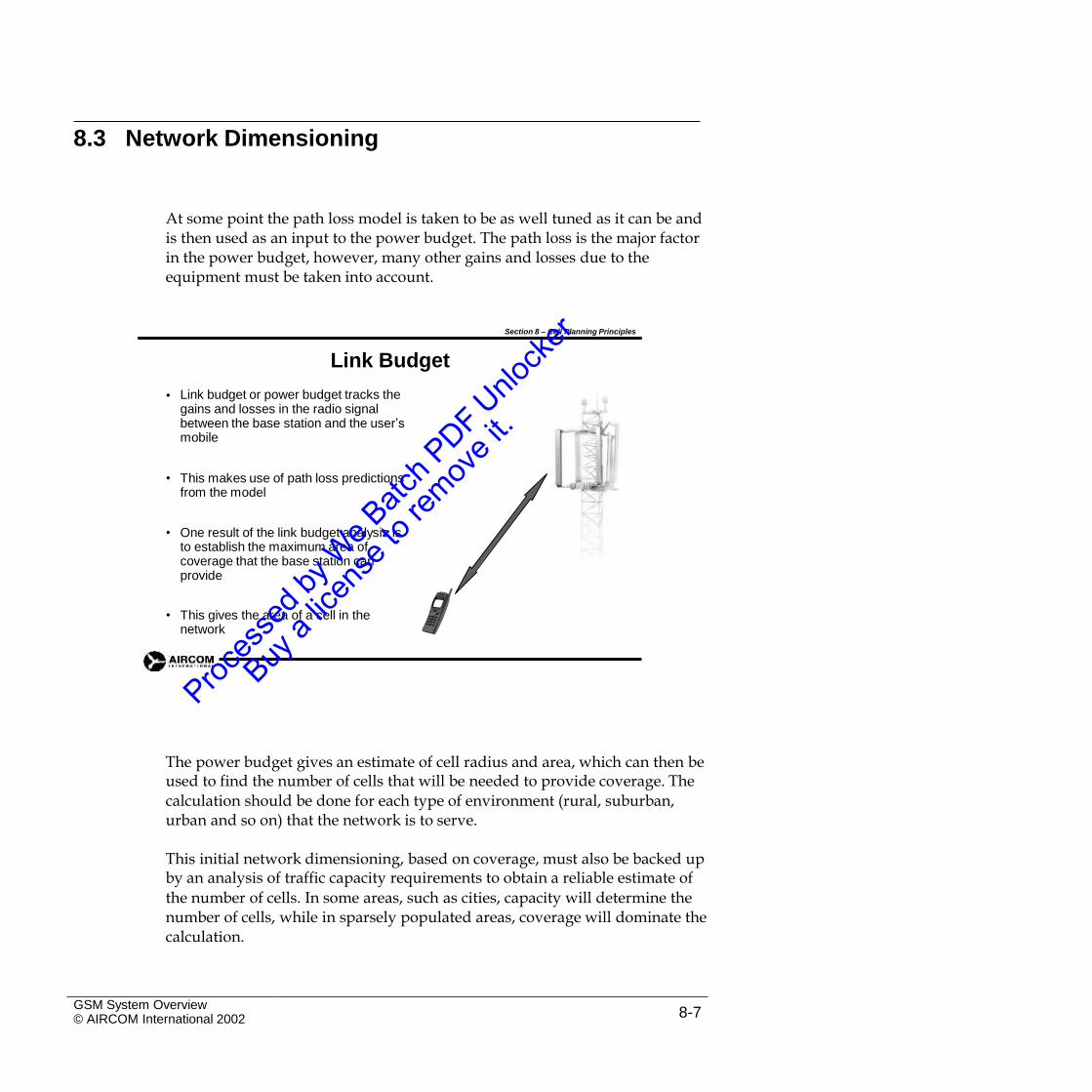
8.3 Network Dimensioning
At some point the path loss model is taken to be as well tuned as it can be andis then used as an input to the power budget. The path loss is the major factor in the power budget, however, many other gains and losses due to the equipment must be taken into account.
Section 8 – Cell Planning Principles
Link Budget
Link budget or power budget tracks the gains and losses in the radio signal between the base station and the user’s mobile
•
• This makes use of path loss predictions from the model
• One result of the link budget analysis is to establish the maximum area of coverage that the base station can provide
• This gives the area of a cell in the network
The power budget gives an estimate of cell radius and area, which can then beused to find the number of cells that will be needed to provide coverage. The
calculation should be done for each type of environment (rural, suburban, urban and so on) that the network is to serve.
This initial network dimensioning, based on coverage, must also be backed upby an analysis of traffic capacity requirements to obtain a reliable estimate of
the number of cells. In some areas, such as cities, capacity will determine the number of cells, while in sparsely populated areas, coverage will dominate the calculation.
GSM System Overview© AIRCOM International 2002 8-7
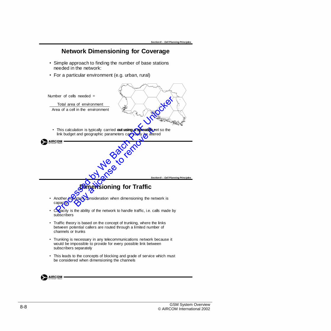
Section 8 – Cell Planning Principles
Network Dimensioning for Coverage
• Simple approach to finding the number of base stations needed in the network:
• For a particular environment (e.g. urban, rural)
=Number of cells needed
Total area of environment
Area of a cell in the environment
• This calculation is typically carried out using a spreadsh so thelink budget and geographic parameters can easily be altered
Section 8 – Cell Planning Principles
Dimensioning for Traffic
• Another important consideration when dimensioning the network is capacity
• Capacity is the ability of the network to handle traffic, i.e. calls made by subscribers
• Traffic theory is based on the concept of trunking, where the links between potential callers are routed through a limited number of channels or trunks
• Trunking is necessary in any telecommunications network because it would be impossible to provide for every possible link between subscribers separately
• This leads to the concepts of blocking and grade of service which must be considered when dimensioning the channels
GSM System Overview© AIRCOM International 20028-8
out using a spreadsh eet
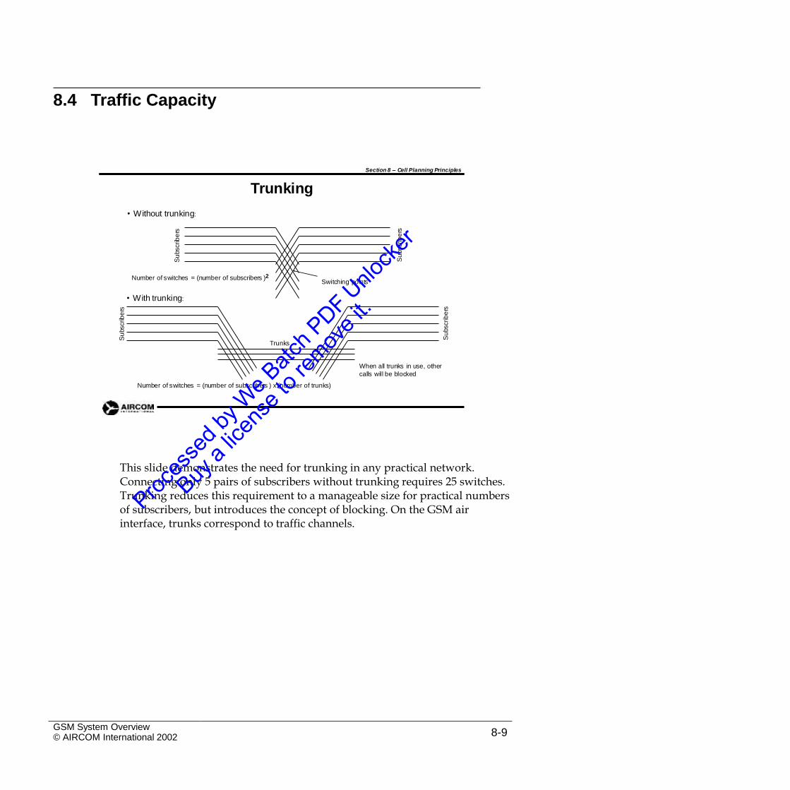
8.4 Traffic Capacity
Section 8 – Cell Planning Principles
Trunking
• Without trunking:
Number of switches = (number of subscribers )2Switching points
• With trunking:
Trunks
When all trunks in use, other
calls will be blocked
Number of switches = (number of subscribers ) x (number of trunks)
This slide demonstrates the need for trunking in any practical network.Connecting only 5 pairs of subscribers without trunking requires 25 switches. Trunking reduces this requirement to a manageable size for practical numbers of subscribers, but introduces the concept of blocking. On the GSM air interface, trunks correspond to traffic channels.
GSM System Overview© AIRCOM International 2002 8-9
Su
bscrib
ers
Su
bscrib
ers
Su
bscrib
ers
Su
bscrib
ers
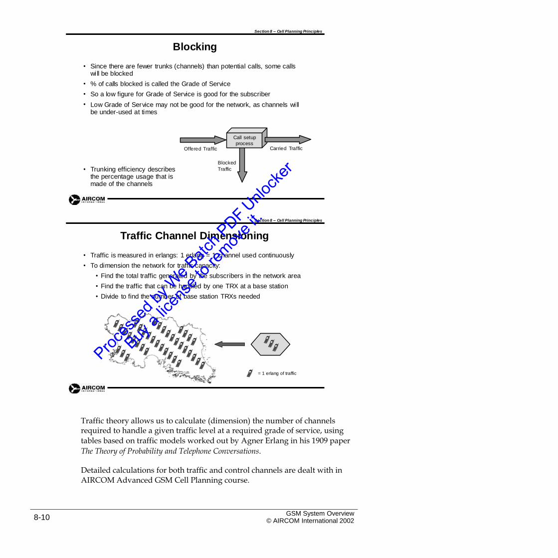
Section 8 – Cell Planning Principles
Blocking
• Since there are fewer trunks (channels) than potential calls, some calls will be blocked
% of calls blocked is called the Grade of Service
So a low figure for Grade of Service is good for the subscriber
Low Grade of Service may not be good for the network, as channels will be under-used at times
•
•
•
Call setup
processCarried TrafficOffered Traffic
Blocked
Traffic• Trunking efficiency describes the percentage usage that is made of the channels
Section 8 – Cell Planning Principles
Traffic Channel Dimensioning
•
•
Traffic is measured in erlangs: 1 erlang = 1 channel used continuously
To dimension the network for traffic capacity:
• Find the total traffic generated by the subscribers in the network area
• Find the traffic that can be handled by one TRX at a base station
• Divide to find the number of base station TRXs needed
= 1 erlang of traffic
Traffic theory allows us to calculate (dimension) the number of channelsrequired to handle a given traffic level at a required grade of service, using
tables based on traffic models worked out by Agner Erlang in his 1909 paper
The Theory of Probability and Telephone Conversations.
Detailed calculations for both traffic and control channels are dealt with inAIRCOM Advanced GSM Cell Planning course.
GSM System Overview© AIRCOM International 20028-10
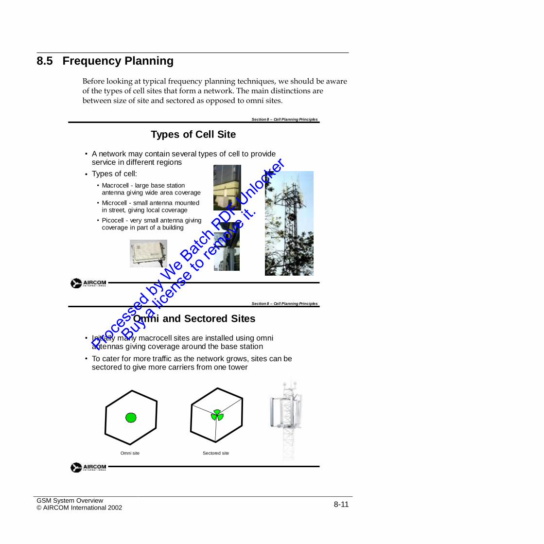
8.5 Frequency Planning
Before looking at typical frequency planning techniques, we should be aware of the types of cell sites that form a network. The main distinctions are between size of site and sectored as opposed to omni sites.
Section 8 – Cell Planning Principles
Types of Cell Site
• A network may contain several types of cell to provide service in different regions
Types of cell:
• Macrocell - large base station antenna giving wide area coverage
• Microcell - small antenna mounted in street, giving local coverage
• Picocell - very small antenna giving coverage in part of a building
•
Section 8 – Cell Planning Principles
Omni and Sectored Sites
• Initially many macrocell sites are installed using omni antennas giving coverage around the base station
To cater for more traffic as the network grows, sites can be sectored to give more carriers from one tower
•
Omni site Sectored site
GSM System Overview© AIRCOM International 2002 8-11
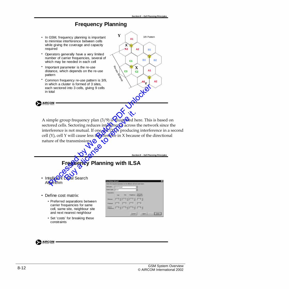
Section 8 – Cell Planning Principles
Frequency Planning
Y• In GSM, frequency planning is important
to minimise interference between cells whi le giving the coverage and capacity required
Operators generally have a very limited number of carrier frequencies, several of which may be needed in each cell
Important parameter is the re-use distance, which depends on the re-use pattern
Common frequency re-use pattern is 3/9, in which a cluster is formed of 3 sites, each sectored into 3 cells, giving 9 cells in total
3/9 PatternA1
XA3 A2 B1
•
B3 B2C1
• XC2 A1C3
•A2A3
Y
A simple group frequency plan (3/9) is illustrated here. This is based onsectored cells. Sectoring reduces interference across the network since the interference is not mutual. If one cell (X) is producing interference in a second cell (Y), cell Y will cause less interference in X because of the directional
nature of the transmission.
Section 8 – Cell Planning Principles
Frequency Planning with ILSA
• Intelligent Local SearchAlgorithm
• Define cost matrix:
• Preferred separations between carrier frequencies for same cell, same site, neighbour site and next nearest neighbour
• Set ‘costs’ for breaking these constraints
GSM System Overview© AIRCOM International 20028-12
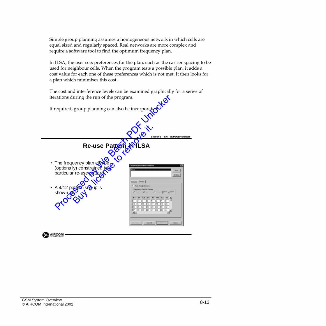
Simple group planning assumes a homogeneous network in which cells areequal sized and regularly spaced. Real networks are more complex and
require a software tool to find the optimum frequency plan.
In ILSA, the user sets preferences for the plan, such as the carrier spacing to beused for neighbour cells. When the program tests a possible plan, it adds a
cost value for each one of these preferences which is not met. It then looks for a plan which minimises this cost.
The cost and interference levels can be examined graphically for a series ofiterations during the run of the program.
If required, group planning can also be incorporated.
Section 8 – Cell Planning Principles
Re-use Pattern in ILSA
• The frequency plan can be (optionally) constrained to a particular re-use pattern
• A 4/12 pattern set up is shown as:
GSM System Overview© AIRCOM International 2002 8-13
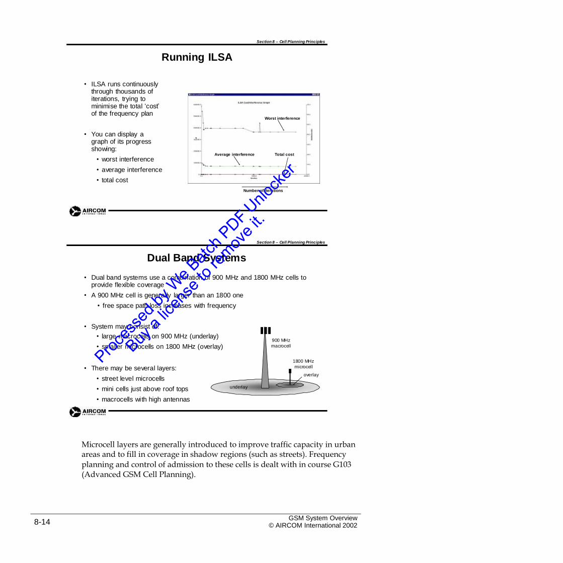
Section 8 – Cell Planning Principles
Running ILSA
• ILSA runs continuously through thousands of iterations, trying to minimise the total ‘cost’ of the frequency plan
Worst interference
• You can display a graph of its progress showing:
• worst interference
• average interference
• total cost
Average interference Total cost
Number of iterations
Section 8 – Cell Planning Principles
Dual Band Systems
• Dual band systems use a combination of 900 MHz and 1800 MHz cells to provide flexible coverage
A 900 MHz cell is generally larger than an 1800 one
• free space path loss increases with frequency
•
• System may consist of:
• large macrocells on 900 MHz (underlay)
• smaller microcells on 1800 MHz (overlay)900 MHz
macrocell
1800 MHz
microcell
overlay
• There may be several layers:
• street level microcells
• mini cells just above roof tops
• macrocells with high antennas
underlay
Microcell layers are generally introduced to improve traffic capacity in urbanareas and to fill in coverage in shadow regions (such as streets). Frequency
planning and control of admission to these cells is dealt with in course G103 (Advanced GSM Cell Planning).
GSM System Overview© AIRCOM International 20028-14
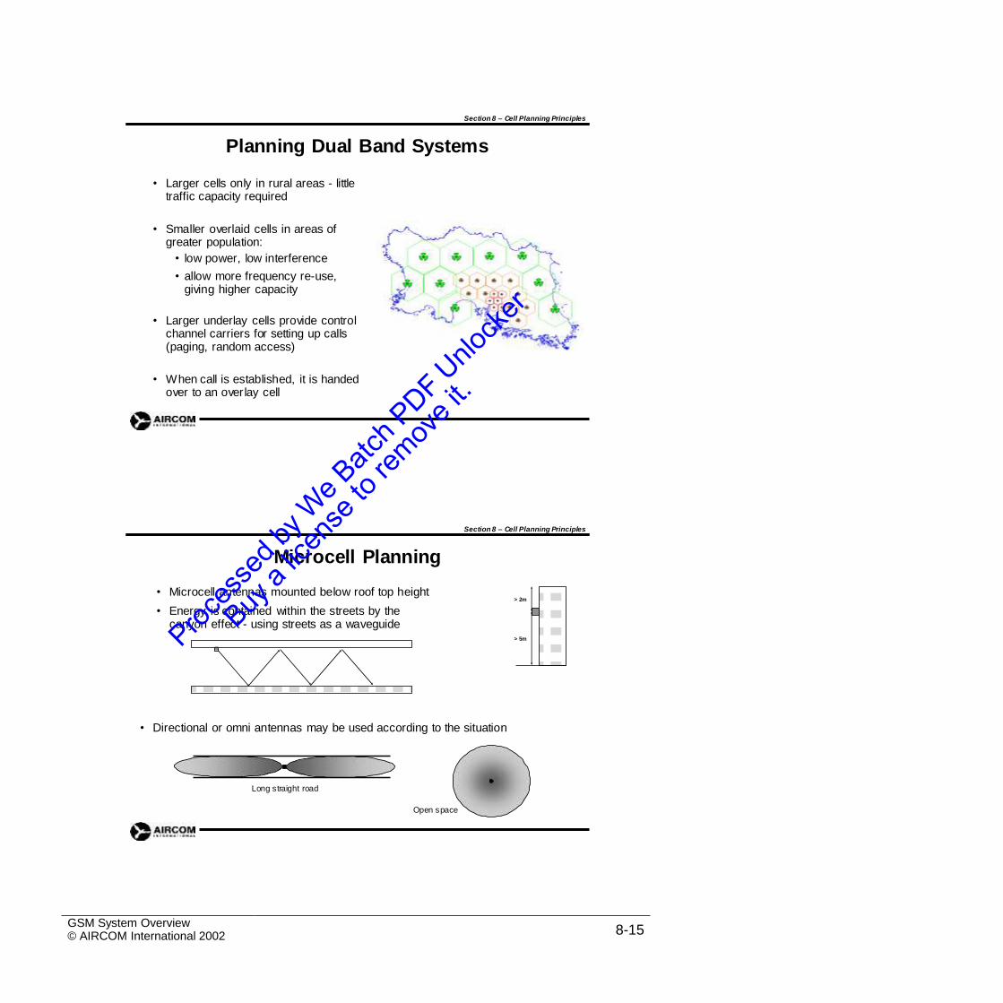
Section 8 – Cell Planning Principles
Planning Dual Band Systems
• Larger cells only in rural areas - little traffic capacity required
• Smaller overlaid cells in areas of greater population:
• low power, low interference
• allow more frequency re-use, giving higher capacity
• Larger underlay cells provide control channel carriers for setting up calls (paging, random access)
• When call is established, it is handed over to an overlay cell
Section 8 – Cell Planning Principles
Microcell Planning
• Microcell antennas mounted below roof top height
• Energy is contained within the streets by the canyon effect - using streets as a waveguide
> 2m
> 5m
• Directional or omni antennas may be used according to the situation
Long straight road
Open space
GSM System Overview© AIRCOM International 2002 8-15
Section 8 – Cell Planning Principles
Summary
Predicting coverage: propagation models, path loss, diffraction, clutter, model tuning
Network dimensioning: coverage, capacity
Traffic capacity: trunking, blocking
Frequency planning: omni, sectored cells, re-use patterns, ILSA
Dual band systems: macrocells, microcells, underlay, overlay
•
•
•
•
•
GSM System Overview© AIRCOM International 20028-16
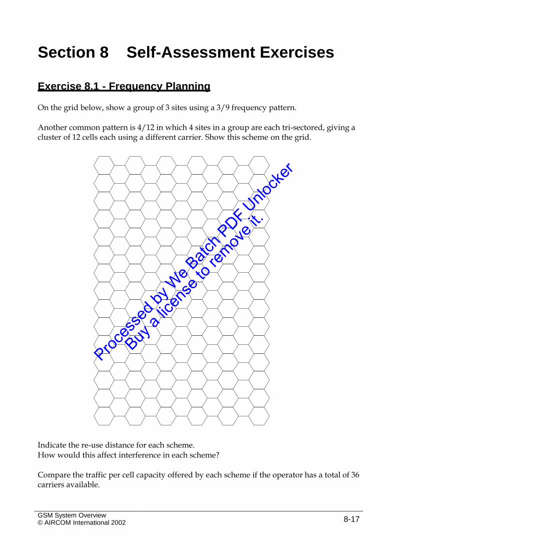
Section 8 Self-Assessment Exercises
Exercise 8.1 - Frequency Planning
On the grid below, show a group of 3 sites using a 3/9 frequency pattern.
Another common pattern is 4/12 in which 4 sites in a group are each tri-sectored, giving acluster of 12 cells each using a different carrier. Show this scheme on the grid.
Indicate the re-use distance for each scheme.How would this affect interference in each scheme?
Compare the traffic per cell capacity offered by each scheme if the operator has a total of 36carriers available.
GSM System Overview© AIRCOM International 2002 8-17
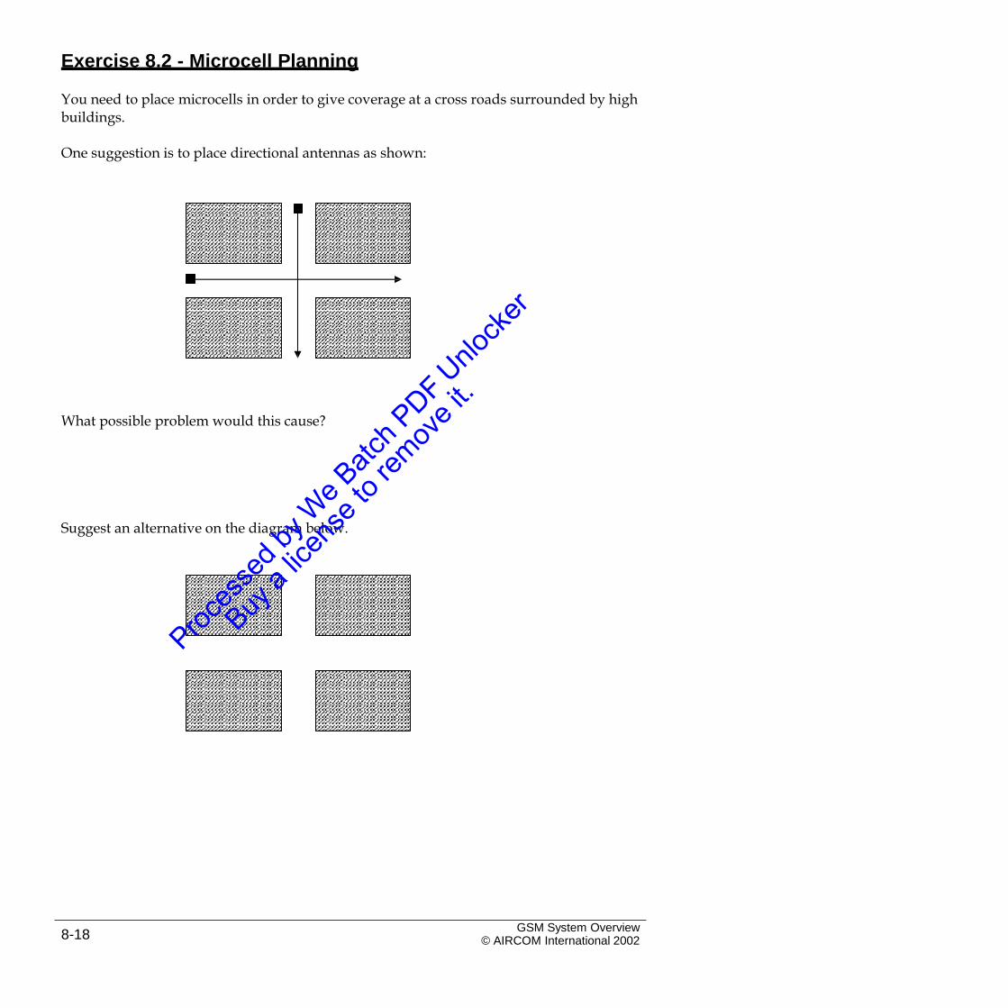
Exercise 8.2 - Microcell Planning
You need to place microcells in order to give coverage at a cross roads surrounded by highbuildings.
One suggestion is to place directional antennas as shown:
What possible problem would this cause?
Suggest an alternative on the diagram below.
GSM System Overview© AIRCOM International 20028-18
9. Cell Planning Options
9.1 Introduction
The cell planning options described in this section may be implemented inparticular cells in order to improve performance. The options described include:
Frequency Hopping (FH)Diversity Reception
Discontinuous Transmission (DTX)
The cell planning options described in this section may be implemented inparticular cells in order to improve performance.
GSM System Overview© AIRCOM International 2002 9-1
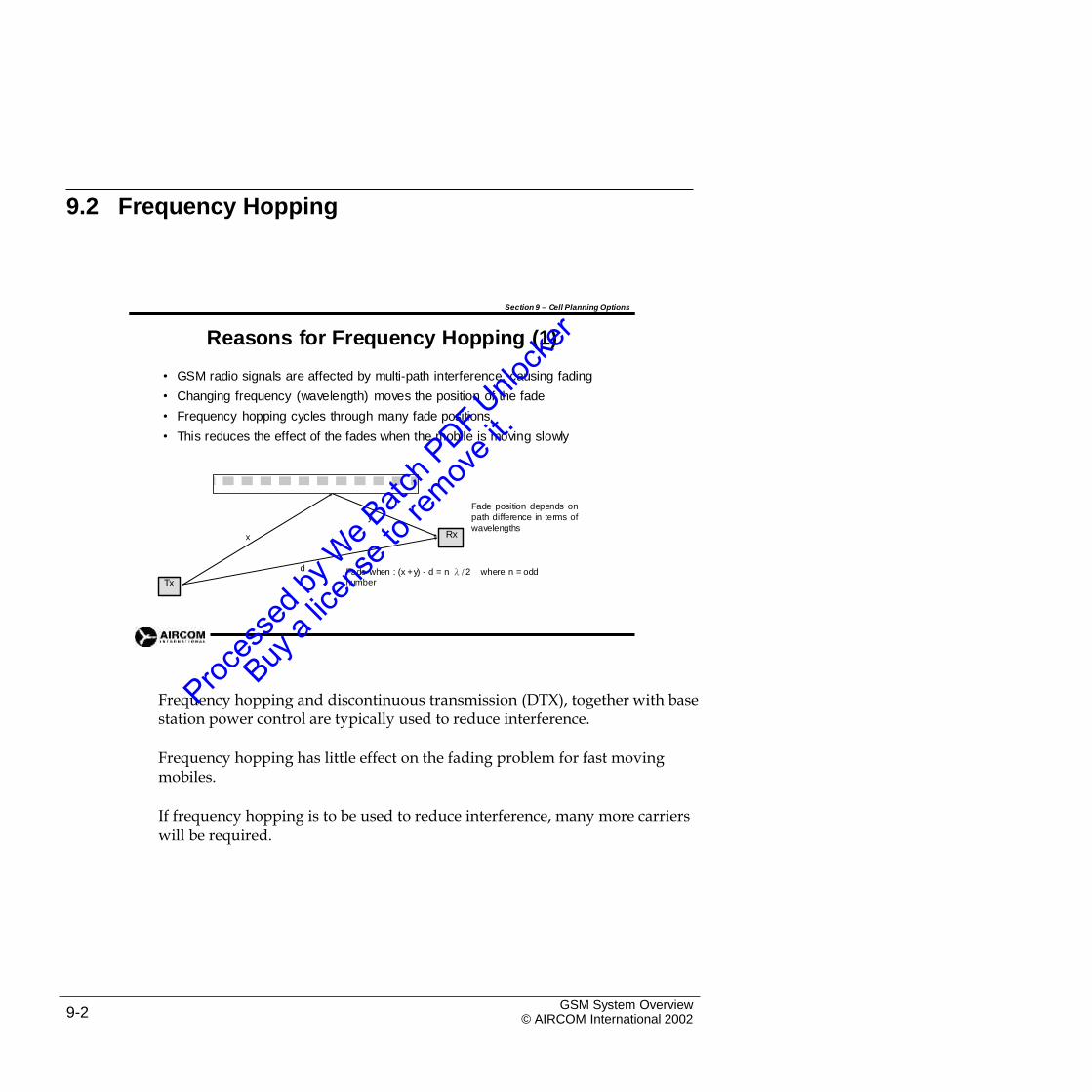
9.2 Frequency Hopping
Section 9 – Cell Planning Options
Reasons for Frequency Hopping (1)
•
•
•
•
GSM radio signals are affected by multi-path interference, causing fading
Changing frequency (wavelength) moves the position of the fade
Frequency hopping cycles through many fade positions
This reduces the effect of the fades when the mobile is moving slowly
Fade position depends on
path difference in terms of
wavelengthsy
x
d Fade when : (x +y) - d = n λ/2 where n = oddnumber
Frequency hopping and discontinuous transmission (DTX), together with basestation power control are typically used to reduce interference.
Frequency hopping has little effect on the fading problem for fast movingmobiles.
If frequency hopping is to be used to reduce interference, many more carrierswill be required.
GSM System Overview© AIRCOM International 20029-2
Tx
Rx
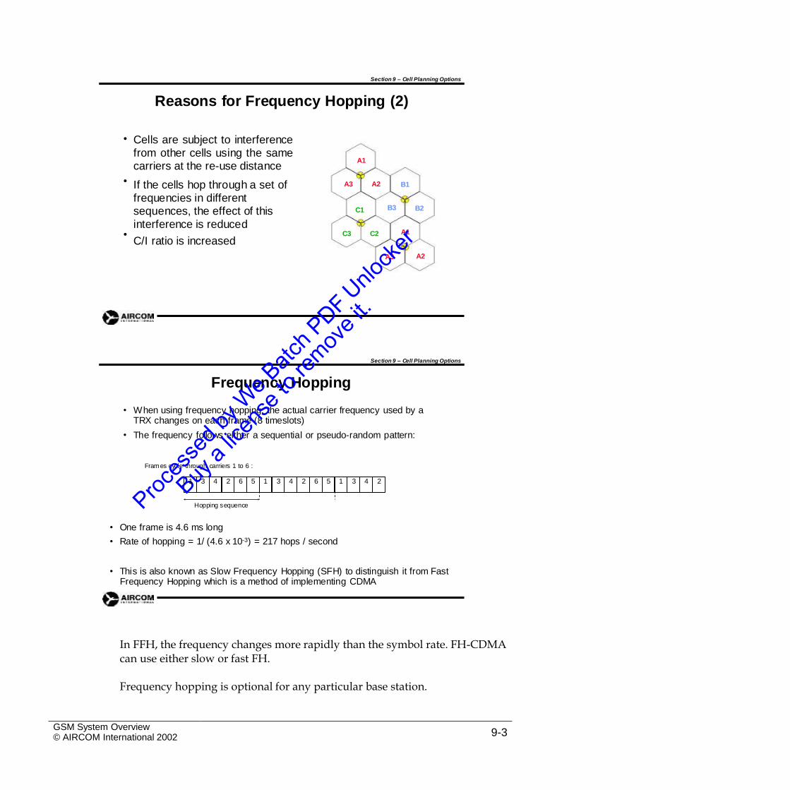
Section 9 – Cell Planning Options
Reasons for Frequency Hopping (2)
• Cells are subject to interferencefrom other cells using the samecarriers at the re-use distance
If the cells hop through a set of frequencies in different sequences, the effect of this interference is reduced
C/I ratio is increased
A1
• A3 A2 B1
B3 B2C1
A1• C3 C2
A2A3
Section 9 – Cell Planning Options
Frequency Hopping
• When using frequency hopping, the actual carrier frequency used by aTRX changes on each frame (8 timeslots)
The frequency follows either a sequential or pseudo-random pattern:•
Frames cycle through carriers 1 to 6 :
Hopping sequence
• One frame is 4.6 ms long
• Rate of hopping = 1/ (4.6 x 10⁻³) = 217 hops / second
• This is also known as Slow Frequency Hopping (SFH) to distinguish it from FastFrequency Hopping which is a method of implementing CDMA
In FFH, the frequency changes more rapidly than the symbol rate. FH-CDMAcan use either slow or fast FH.
Frequency hopping is optional for any particular base station.
GSM System Overview© AIRCOM International 2002 9-3
1 3 4 2 6 5 1 3 4 2 6 5 1 3 4 2
Section 9 – Cell Planning Options
Frequency Hopping at the BTS
• If the BTS has implemented SFH:
• TRXs used only for traffic channels will hop through set sequences
• TRX used for the BCCH carrier will not hop - mobiles must be able to access this for neighbour cell power level measurements
• 64 hopping sequences are available in GSM:
• 1 sequence is cyclic - 1,2,3 …, 1,2 …
• 63 others are pseudo random patterns
Hop Sequence Number (HSN) defines the sequence in use•
• The set of carrier frequencies assigned to the sequence (MobileAllocation) must be different for each TRX
Section 9 – Cell Planning Options
Frequency Hopping at the Mobile
•
•
Base stations need not implement frequency hopping
Mobile must be capable of SFH in case it enters a cell in which it is implemented
In addition to hopping in step with the BTS, the mobile must also make measurements on adjacent cells
This is why the rate of hopping is limited to SFH in GSM
•
•
• The mobile needs to know:
• Frequencies used for hopping (Mobile Allocation)
• Hop Sequence Number (HSN)
• Start frequency (Mobile Allocation Index Offset, MAIO)
The frequency hopping information above is included in the handovermessage when a mobile enters a cell that is using frequency hopping.
GSM System Overview© AIRCOM International 20029-4
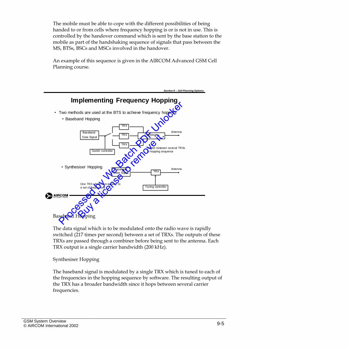
The mobile must be able to cope with the different possibilities of beinghanded to or from cells where frequency hopping is or is not in use. This is controlled by the handover command which is sent by the base station to the mobile as part of the handshaking sequence of signals that pass between the MS, BTSs, BSCs and MSCs involved in the handover.
An example of this sequence is given in the AIRCOM Advanced GSM CellPlanning course.
Section 9 – Cell Planning Options
Implementing Frequency Hopping
• Two methods are used at the BTS to achieve frequency hopping:
• Baseband Hopping
Antenna
Data Signal
Switch between several TRXs
in hopping sequence
• Synthesiser HoppingAntenna
One TRX which is re-tunable to
a set of frequencies
Baseband Hopping
The data signal which is to be modulated onto the radio wave is rapidlyswitched (217 times per second) between a set of TRXs. The outputs of these TRXs are passed through a combiner before being sent to the antenna. Each TRX output is a single carrier bandwidth (200 kHz).
Synthesiser Hopping
The baseband signal is modulated by a single TRX which is tuned to each ofthe frequencies in the hopping sequence by software. The resulting output of
the TRX has a broader bandwidth since it hops between several carrier frequencies.
GSM System Overview© AIRCOM International 2002 9-5
Tuning controller
BasebandData Signal TRX
Switch controller
Baseband
TRX
TRX Combiner
TRX
The difference in bandwidth produced by baseband and synthesiser hoppinghas implications for the type of combiner equipment that can be used at the
base station. This is discussed fully in the AIRCOM Advanced GSM Cell
Planning course.
9.3 Diversity Reception
Diversity reception gives extra gain on the uplink by reducing fading at thebase station antenna.
Section 9 – Cell Planning Options
Diversity Reception
• Diversity reception is a way to improve the quality and strength of the signal arriving at the base station, by receiving it in several independent ways
• Two forms of diversity reception often employed are:
• Polarisation diversity
• Space diversity
• Frequency hopping is sometimes referred to as frequency diversity
Diversity reception introduces a gain into the uplink power budget typicallyof about 5dB. A base station may use one or other method of diversity, but would not generally use both.
GSM System Overview© AIRCOM International 20029-6
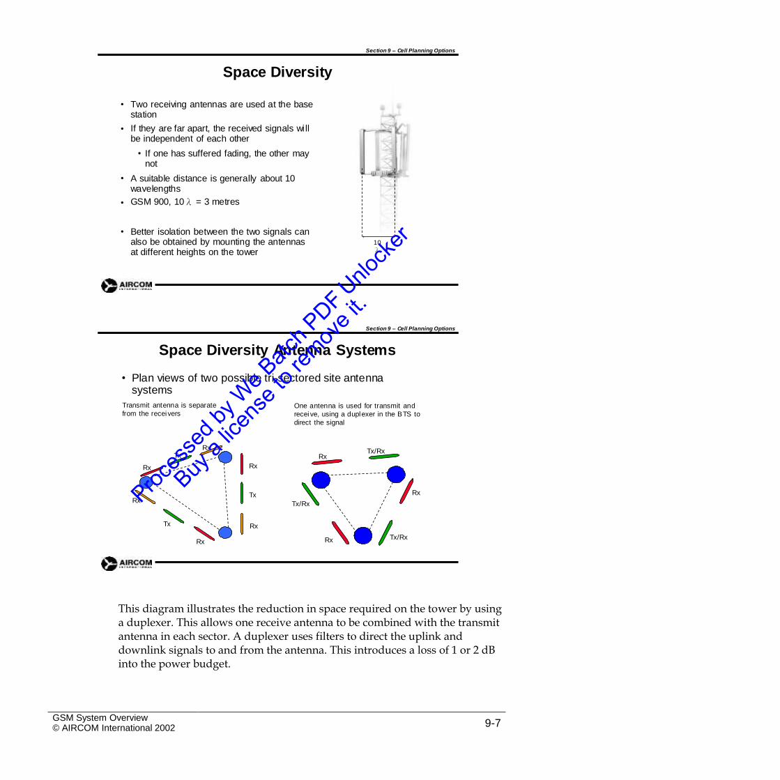
Section 9 – Cell Planning Options
Space Diversity
• Two receiving antennas are used at the base station
If they are far apart, the received signals will be independent of each other
• If one has suffered fading, the other may not
A suitable distance is generally about 10 wavelengths
GSM 900, 10λ = 3 metres
•
•
•
• Better isolation between the two signals can also be obtained by mounting the antennas at different heights on the tower
10λ
Section 9 – Cell Planning Options
Space Diversity Antenna Systems
• Plan views of two possible tri-sectored site antenna systems
Transmit antenna is separate
from the receiversOne antenna is used for transmit and
recei ve, using a duplexer in the BTS to
direct the signal
RxTx/Rx
Tx Rx
RxRx
RxTxRx
Tx/Rx
Tx Rx
Tx/RxRxRx
This diagram illustrates the reduction in space required on the tower by usinga duplexer. This allows one receive antenna to be combined with the transmit antenna in each sector. A duplexer uses filters to direct the uplink and downlink signals to and from the antenna. This introduces a loss of 1 or 2 dB into the power budget.
GSM System Overview© AIRCOM International 2002 9-7
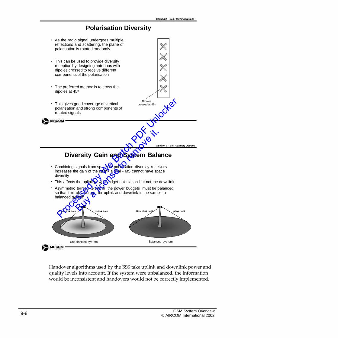
Section 9 – Cell Planning Options
Polarisation Diversity
• As the radio signal undergoes multiplereflections and scattering, the plane ofpolarisation is rotated randomly
• This can be used to provide diversity reception by designing antennas with dipoles crossed to receive different components of the polarisation
• The preferred method is to cross the dipoles at 45o
Dipoles crossed at 45o• This gives good coverage of vertical
polarisation and strong components of rotated signals
Section 9 – Cell Planning Options
Diversity Gain and System Balance
• Combining signals from space or polarisation diversity receivers increases the gain of the uplink signal - MS cannot have space diversity
This affects the uplink power budget calculation but not the downlink
Asymmetric terms like this in the power budgets must be balanced so that limit of coverage for uplink and downlink is the same - a balanced system
•
•
Downlink limit Uplink limitDownlink limit Uplink limit
Balanced systemUnbalanc ed system
Handover algorithms used by the BSS take uplink and downlink power andquality levels into account. If the system were unbalanced, the information would be inconsistent and handovers would not be correctly implemented.
GSM System Overview© AIRCOM International 20029-8
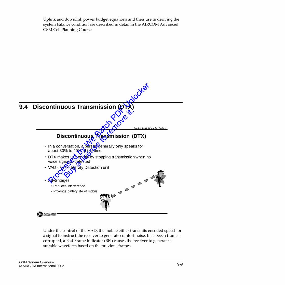
Uplink and downlink power budget equations and their use in deriving thesystem balance condition are described in detail in the AIRCOM Advanced
GSM Cell Planning Course
9.4 Discontinuous Transmission (DTX)
Section 9 – Cell Planning Options
Discontinuous Transmission (DTX)
• In a conversation, a person generally only speaks for about 30% to 40% of the time
DTX makes use of this by stopping transmission when no voice signal is detected
VAD - Voice Activity Detection unit
•
•
• Advantages:
• Reduces interference
• Prolongs battery life of mobile
Under the control of the VAD, the mobile either transmits encoded speech ora signal to instruct the receiver to generate comfort noise. If a speech frame is
corrupted, a Bad Frame Indicator (BFI) causes the receiver to generate a suitable waveform based on the previous frames.
GSM System Overview© AIRCOM International 2002 9-9
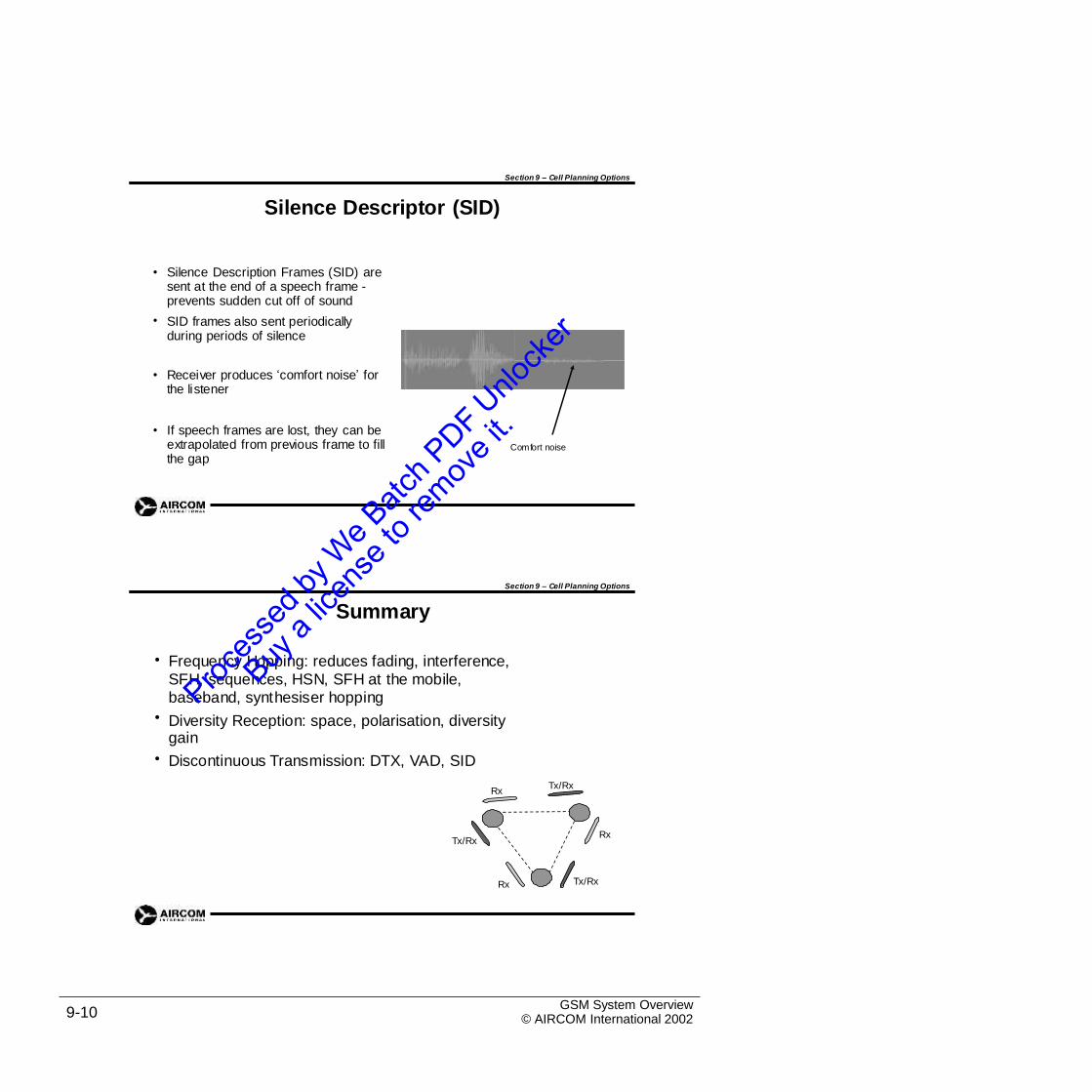
Section 9 – Cell Planning Options
Silence Descriptor (SID)
• Silence Description Frames (SID) are sent at the end of a speech frame -prevents sudden cut off of sound
SID frames also sent periodically during periods of silence
•
• Receiver produces ‘comfort noise’ for the listener
• If speech frames are lost, they can be extrapolated from previous frame to fill the gap
Comfort noise
Section 9 – Cell Planning Options
Summary
• Frequency Hopping: reduces fading, interference, SFH, sequences, HSN, SFH at the mobile, baseband, synthesiser hopping
Diversity Reception: space, polarisation, diversity gain
Discontinuous Transmission: DTX, VAD, SID
•
•
Tx/RxRx
RxTx/Rx
Tx/RxRx
GSM System Overview© AIRCOM International 20029-10
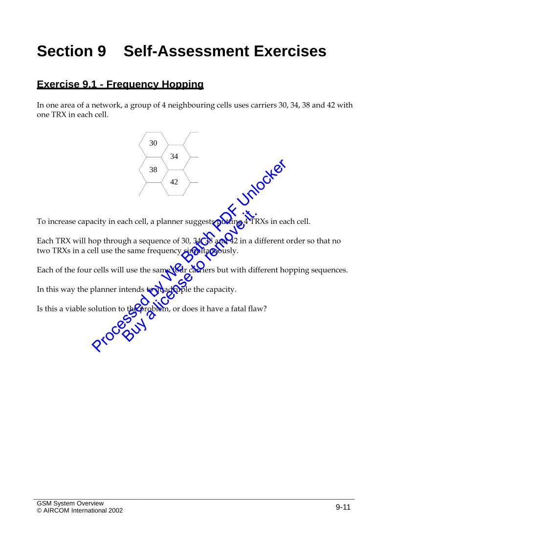
Section 9 Self-Assessment Exercises
Exercise 9.1 - Frequency Hopping
In one area of a network, a group of 4 neighbouring cells uses carriers 30, 34, 38 and 42 withone TRX in each cell.
30
34
38
42
To increase capacity in each cell, a planner suggests putting 4 TRXs in each cell.
Each TRX will hop through a sequence of 30, 34, 38 and 42 in a different order so that notwo TRXs in a cell use the same frequency simultaneously.
Each of the four cells will use the same four carriers but with different hopping sequences.
In this way the planner intends to quadruple the capacity.
Is this a viable solution to the problem, or does it have a fatal flaw?
GSM System Overview© AIRCOM International 2002 9-11
Intentional Blank Page
GSM System Overview© AIRCOM International 20029-12
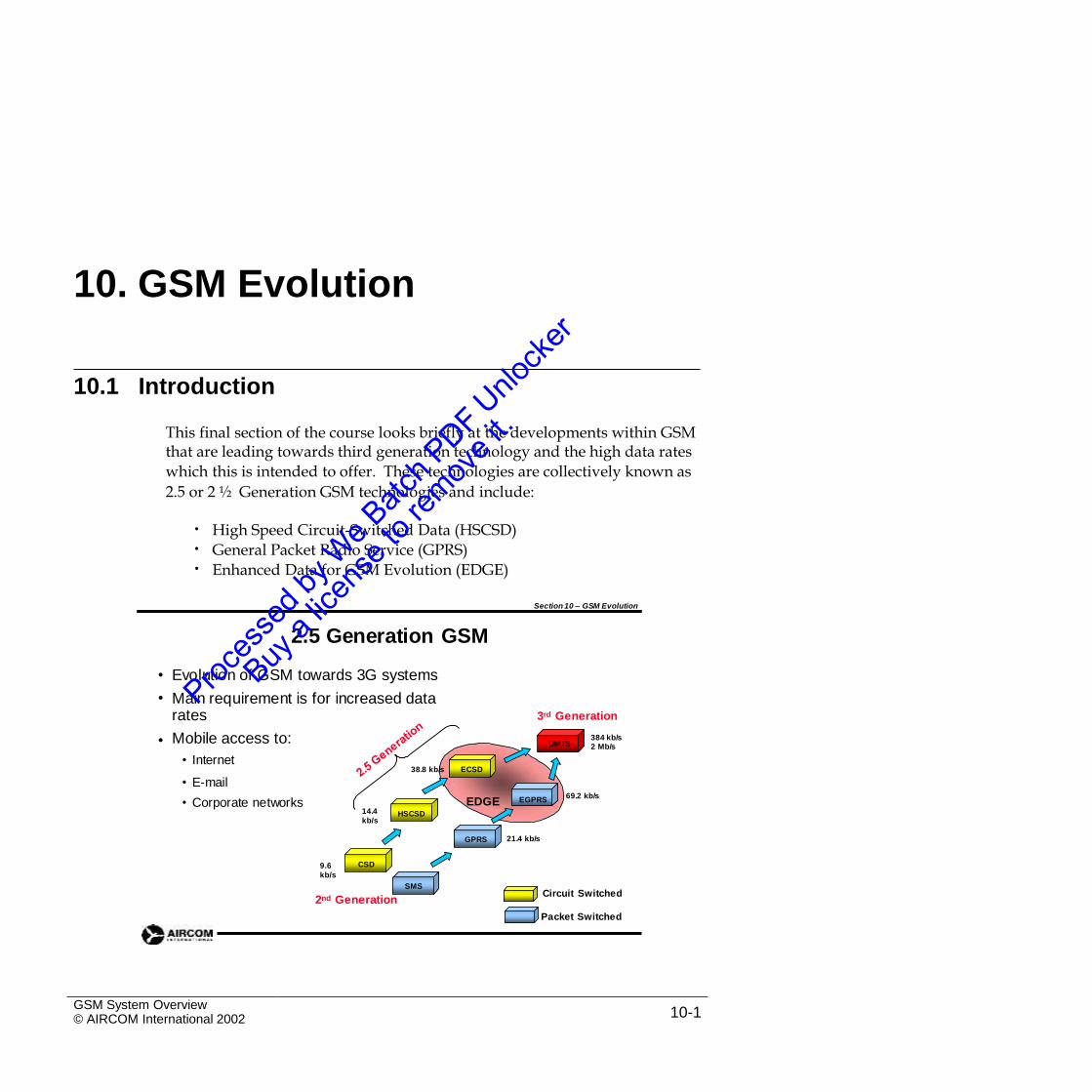
CSD
10. GSM Evolution
10.1 Introduction
This final section of the course looks briefly at the developments within GSMthat are leading towards third generation technology and the high data rates
which this is intended to offer. These technologies are collectively known as
2.5 or 2 ½ Generation GSM technologies and include:
•
•
•
High Speed Circuit-Switched Data (HSCSD)
General Packet Radio Service (GPRS)
Enhanced Data for GSM Evolution (EDGE)
Section 10 – GSM Evolution
2.5 Generation GSM
•
•
Evolution of GSM towards 3G systems
Main requirement is for increased data rates
Mobile access to:
• Internet
3rd Generation
• 384 kb/s2 Mb/sUMTS
38.8 kb/s ECSD
• E-mail69.2 kb/s
• Corporate networks EDGE EGPRS
14.4
kb/sHSCSD
21.4 kb/sGPRS
CSD9.6
kb/s
SMSCircuit Switched
2nd Generation
Packet Switched
GSM System Overview© AIRCOM International 2002 10-1
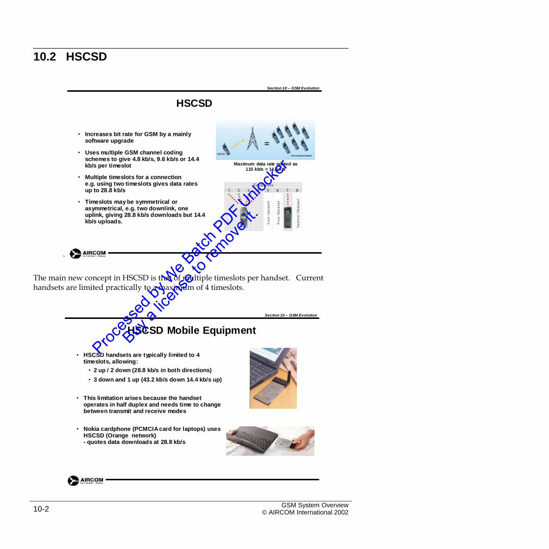
10.2 HSCSD
Section 10 – GSM Evolution
HSCSD
• Increases bit rate for GSM by a mainly software upgrade
• Uses multiple GSM channel coding schemes to give 4.8 kb/s, 9.6 kb/s or 14.4 kb/s per timeslot Maximum data rate quoted as
115 kb/s = 14.4 x 8
• Multiple timeslots for a connectione.g. using two timeslots gives data rates up to 28.8 kb/s
• Timeslots may be symmetrical or asymmetrical, e.g. two downlink, one uplink, giving 28.8 kb/s downloads but 14.4 kb/s uploads.
`
The main new concept in HSCSD is that of multiple timeslots per handset. Currenthandsets are limited practically to a maximum of 4 timeslots.
Section 10 – GSM Evolution
HSCSD Mobile Equipment
• HSCSD handsets are typically limited to 4 timeslots, allowing:
• 2 up / 2 down (28.8 kb/s in both directions)
• 3 down and 1 up (43.2 kb/s down 14.4 kb/s up)
• This limitation arises because the handset operates in half duplex and needs time to change between transmit and receive modes
• Nokia cardphone (PCMCIA card for laptops) usesHSCSD (Orange network)- quotes data downloads at 28.8 kb/s
GSM System Overview© AIRCOM International 200210-2
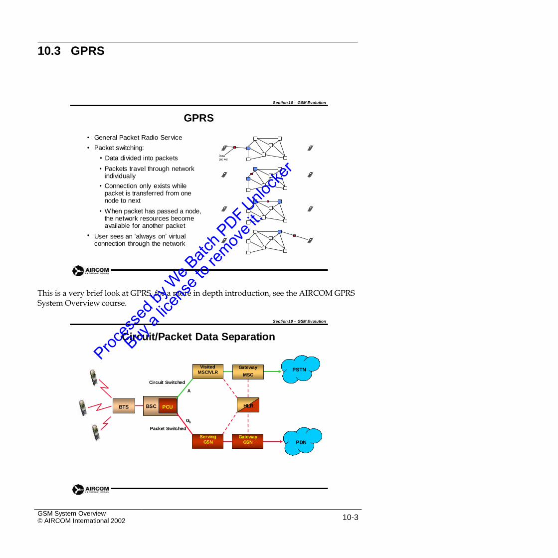
10.3 GPRS
Section 10 – GSM Evolution
GPRS
•
•
General Packet Radio Service
Packet switching:
• Data divided into packets
• Packets travel through network individually
• Connection only exists while packet is transferred from one node to next
• When packet has passed a node, the network resources become available for another packet
User sees an ‘always on’ virtual connection through the network
Data pac ket
•
This is a very brief look at GPRS, for a more in depth introduction, see the AIRCOM GPRSSystem Overview course.
Section 10 – GSM Evolution
Circuit/Packet Data Separation
MSC
Circuit Switched
A
HLR
Gb
Packet Switched
GSM System Overview© AIRCOM International 2002 10-3
PDNServing
GSN
BTS BSC PCU
Gateway
GatewayGSN
VisitedMSC/VLR
PSTN
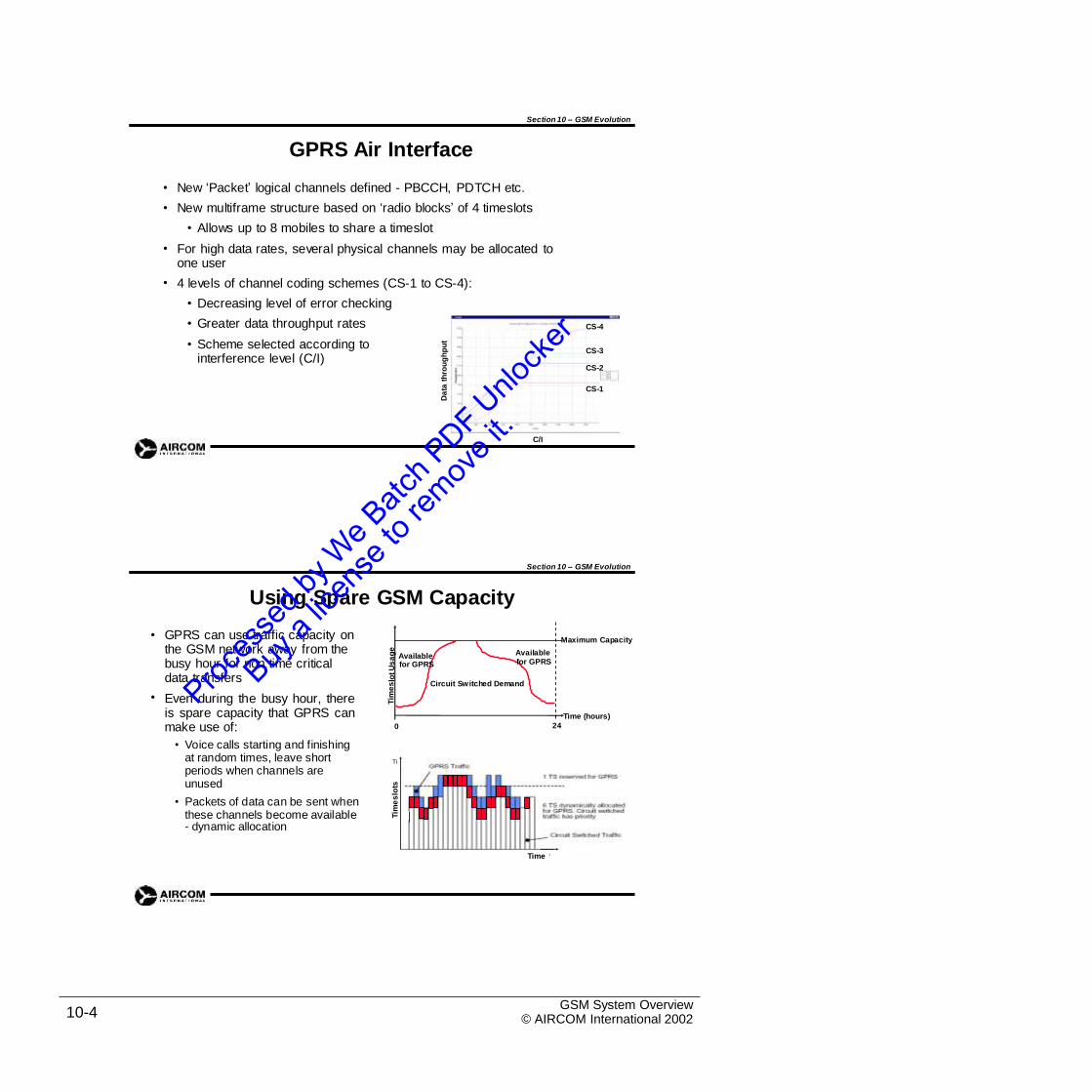
T ime
m esl ots
Section 10 – GSM Evolution
GPRS Air Interface
•
•
New ‘Packet’ logical channels defined - PBCCH, PDTCH etc.
New multiframe structure based on ‘radio blocks’ of 4 timeslots
• Allows up to 8 mobiles to share a timeslot
For high data rates, several physical channels may be allocated to one user
4 levels of channel coding schemes (CS-1 to CS-4):
• Decreasing level of error checking
• Greater data throughput rates
• Scheme selected according to interference level (C/I)
•
•
CS-4
CS-3
CS-2
CS-1
C/I
Section 10 – GSM Evolution
Using Spare GSM Capacity
• GPRS can use traffic capacity on the GSM network away from the busy hour for non time critical data transfers
Even during the busy hour, thereis spare capacity that GPRS canmake use of:
• Voice calls starting and finishing at random times, leave short periods when channels are unused
• Packets of data can be sent when these channels become available- dynamic allocation
Maximum Capacity
•
Time (hours)
240
GSM System Overview© AIRCOM International 200210-4
Tim
es
lotU
sa
ge
Tim
es
lots
Da
tath
rou
gh
pu
t
Time
Ti
Available Available
for GPRS for GPRS
Circuit Switched Demand
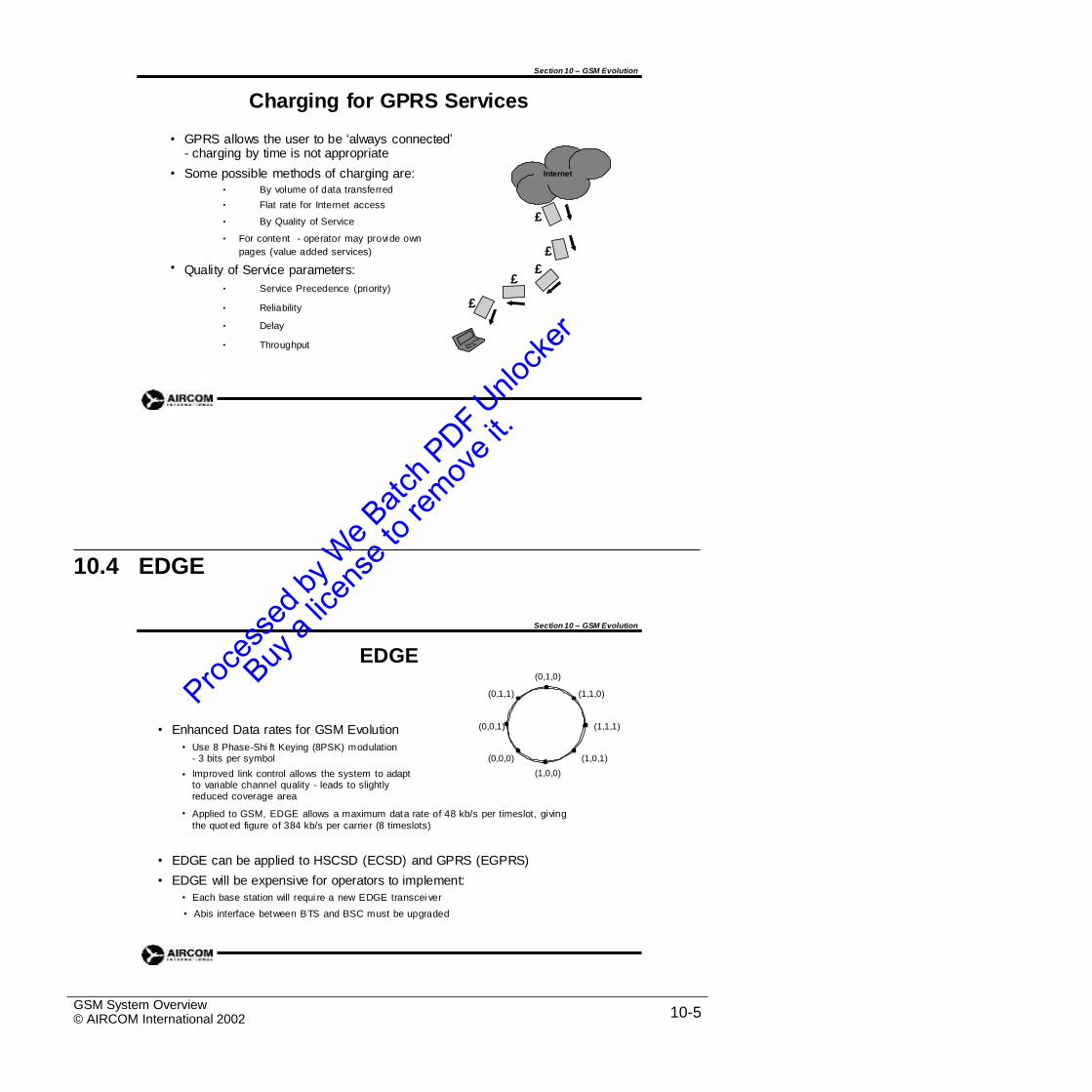
Section 10 – GSM Evolution
Charging for GPRS Services
• GPRS allows the user to be ‘always connected’- charging by time is not appropriate
Some possible methods of charging are:• By volume of data transferred
• Flat rate for Internet access
• By Quality of Service
• For content - operator may provide own
pages (value added services)
Quality of Service parameters:
• Service Precedence (priority)
• Reliability
• Delay
• Throughput
•
£
£
• ££
£
10.4 EDGE
Section 10 – GSM Evolution
EDGE(0,1,0)
(0,1,1) (1,1,0)
(0,0,1) (1,1,1)• Enhanced Data rates for GSM Evolution
• Use 8 Phase-Shi ft Keying (8PSK) modulation- 3 bits per symbol
Improved link control allows the system to adapt to variable channel quality - leads to slightly reduced coverage area
(0,0,0) (1,0,1)
(1,0,0)•
• Applied to GSM, EDGE allows a maximum data rate of 48 kb/s per timeslot, giving
the quot ed figure of 384 kb/s per carrier (8 timeslots)
•
•
EDGE can be applied to HSCSD (ECSD) and GPRS (EGPRS)
EDGE will be expensive for operators to implement:
• Each base station will requi re a new EDGE transcei ver
• Abis interface between BTS and BSC must be upgraded
GSM System Overview© AIRCOM International 2002 10-5
Internet
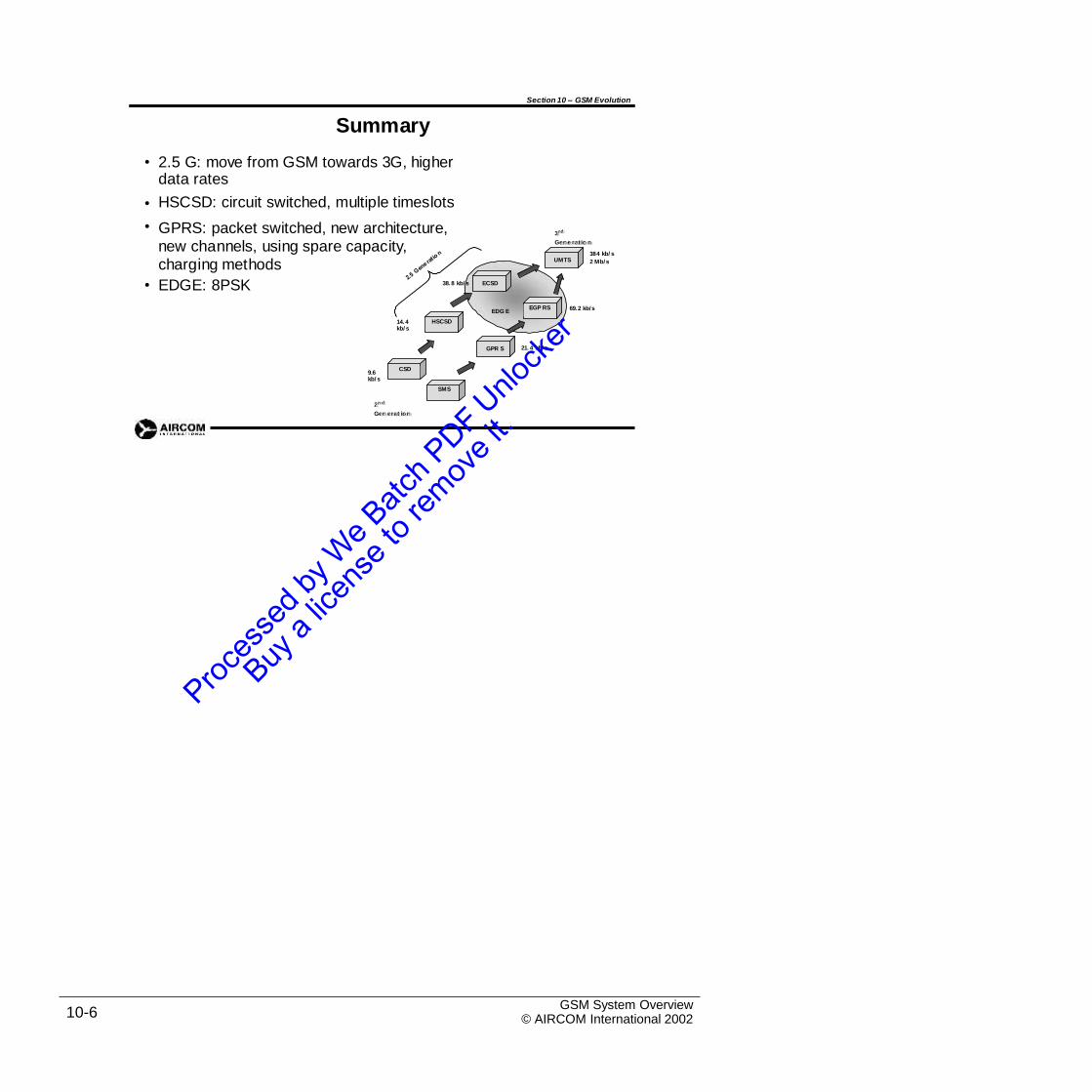
CSD
Section 10 – GSM Evolution
Summary
2.5 G: move from GSM towards 3G, higher data rates
HSCSD: circuit switched, multiple timeslots
GPRS: packet switched, new architecture, new channels, using spare capacity, charging methods
•
•
•33
rrdd
Geenneerraattiioonn
384 kb/ s
2 Mb/ sUMTS
• EDGE: 8PSK 38. 8 kb/ s ECSD
69.2 kb/sEDG E
14. 4 kb/ s
21. 4 kb/ sGPR S
9.6 kb/ s
22nndd
Geenneerraattiioonn
GSM System Overview© AIRCOM International 200210-6
SMS
CSD
HSCSD
EGP RS
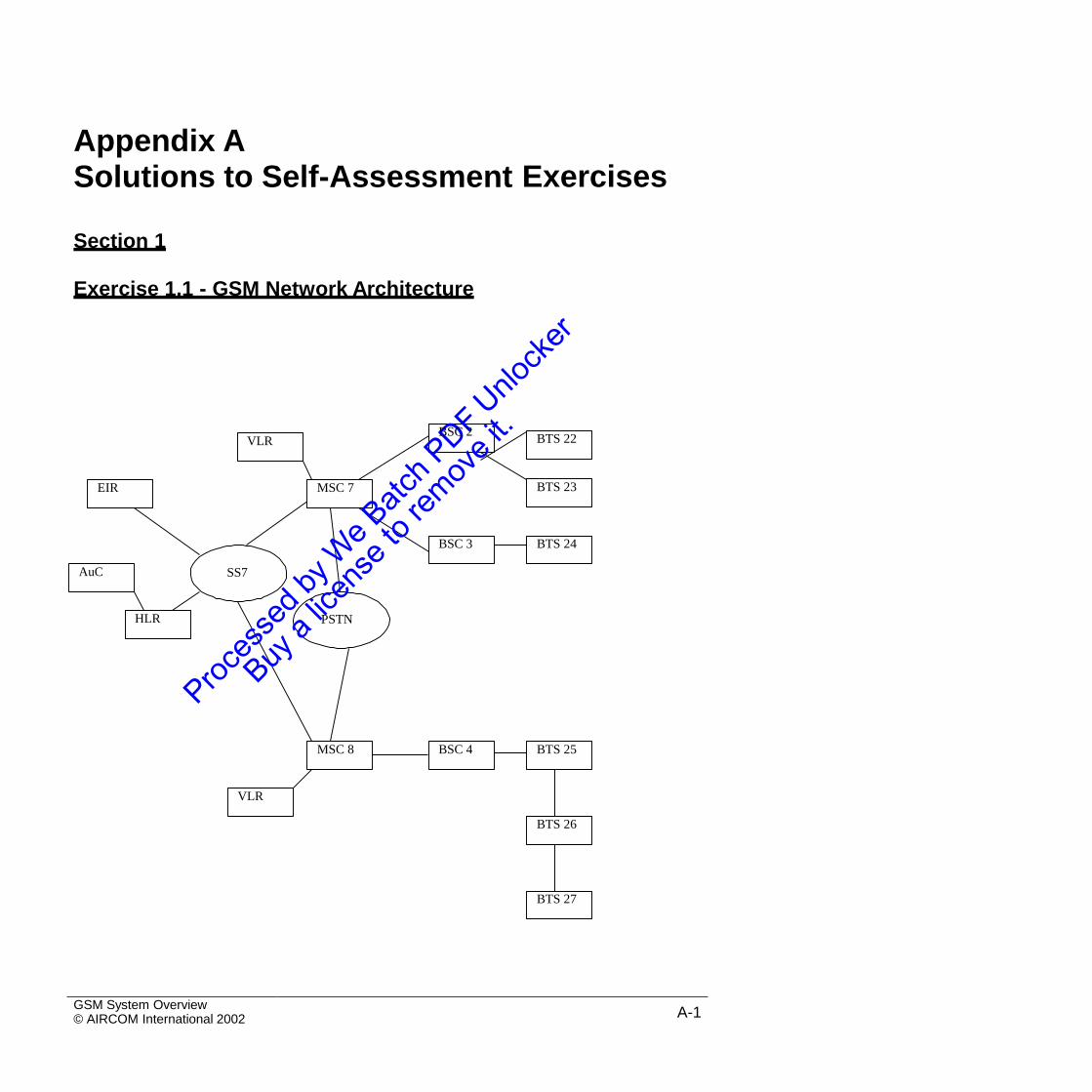
Appendix ASolutions to Self-Assessment Exercises
Section 1
Exercise 1.1 - GSM Network Architecture
SS7
PSTN
GSM System Overview© AIRCOM International 2002 A-1
VLR
MSC 8 BSC 4 BTS 25
BTS 26
BTS 27
HLR
AuC
BSC 3 BTS 24
BTS 23MSC 7EIR
BTS 22VLRBSC 2
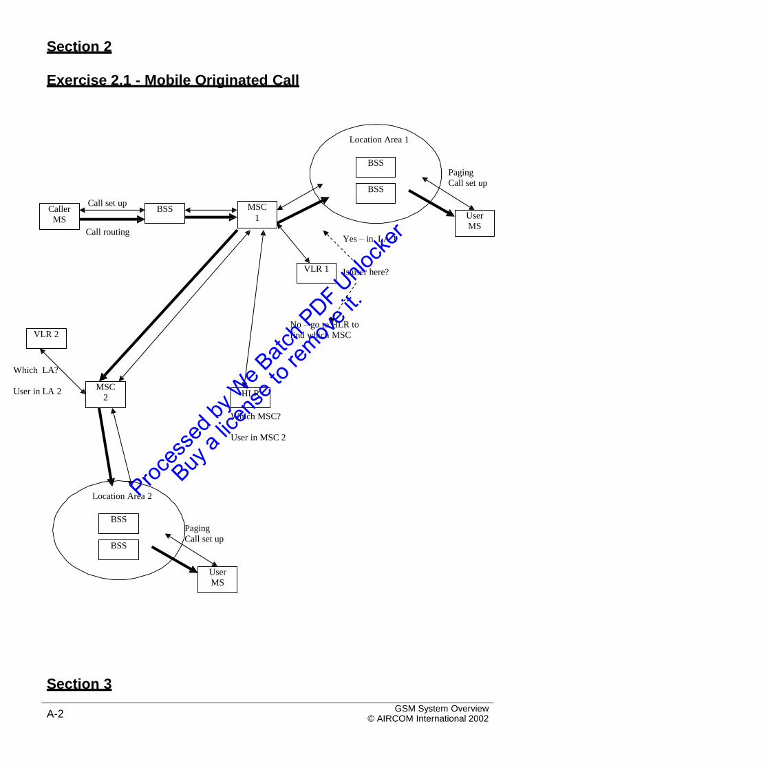
Section 2
Exercise 2.1 - Mobile Originated Call
Location Area 1
Paging
Call set up
Call set up
Call routingYes – in LA 1
Is user here?
No – go to HLR to
find which MSC
Which LA?
User in LA 2
Which MSC?
User in MSC 2
Location Area 2
Paging
Call set up
Section 3
GSM System Overview© AIRCOM International 2002A-2
User
MS
BSS
BSS
HLRMSC
2
VLR 2
VLR 1
User
MS
MSC
1BSSCaller
MS
BSS
BSS
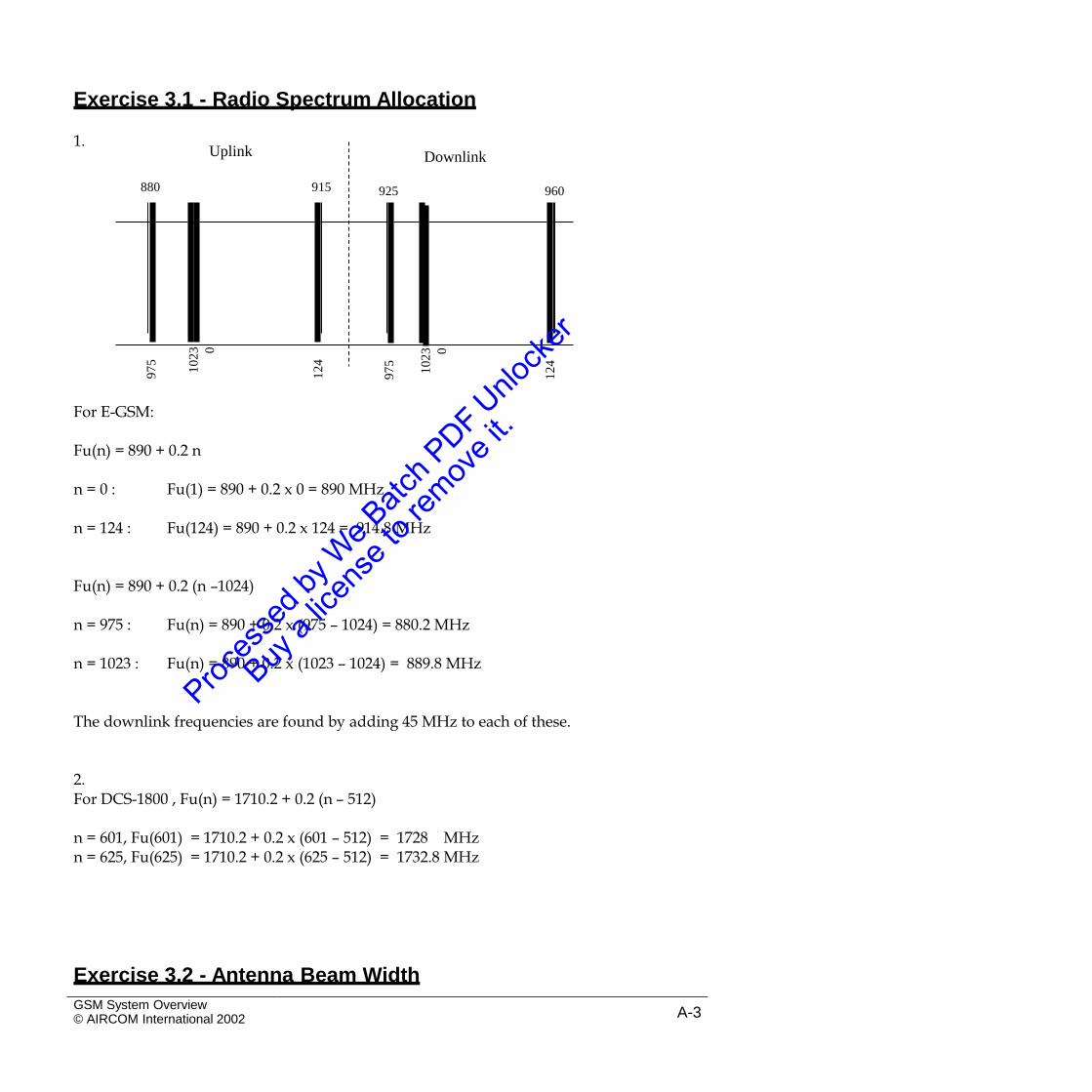
Exercise 3.1 - Radio Spectrum Allocation
1.Downlink
For E-GSM:
Fu(n) = 890 + 0.2 n
n = 0 : Fu(1) = 890 + 0.2 x 0 = 890 MHz
n = 124 : Fu(124) = 890 + 0.2 x 124 = 914.8 MHz
Fu(n) = 890 + 0.2 (n –1024)
n = 975 : Fu(n) = 890 + 0.2 x (975 – 1024) = 880.2 MHz
n = 1023 : Fu(n) = 890 + 0.2 x (1023 – 1024) = 889.8 MHz
The downlink frequencies are found by adding 45 MHz to each of these.
2.For DCS-1800 , Fu(n) = 1710.2 + 0.2 (n – 512)
n = 601, Fu(601) = 1710.2 + 0.2 x (601 – 512) = 1728 MHzn = 625, Fu(625) = 1710.2 + 0.2 x (625 – 512) = 1732.8 MHz
Exercise 3.2 - Antenna Beam Width
GSM System Overview© AIRCOM International 2002 A-3
97
5
10
23 0
12
4
97
5
10
23 0
12
4
Uplink
880 915 925 960
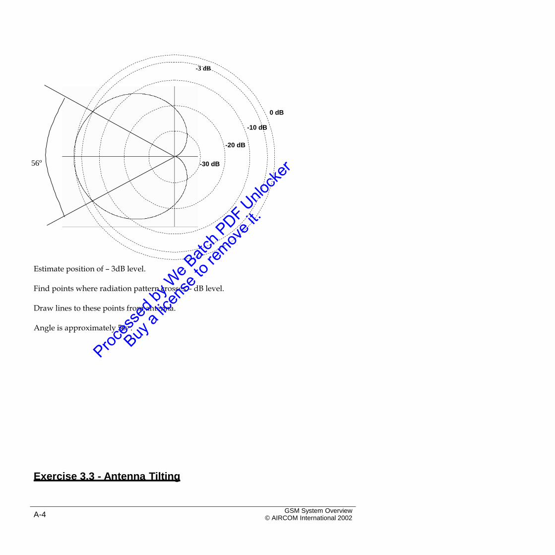
-3 dB
0 dB
-10 dB
-20 dB
56o-30 dB
Estimate position of – 3dB level.
Find points where radiation pattern crosses – dB level.
Draw lines to these points from antenna.
Angle is approximately 56o .
Exercise 3.3 - Antenna Tilting
GSM System Overview© AIRCOM International 2002A-4
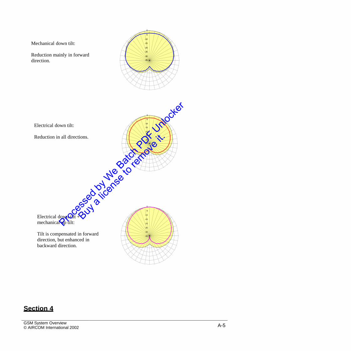
0
Mechanical down tilt:
Reduction mainly in forward
direction. -35
0
Electrical down tilt:
Reduction in all directions.-35
0
Electrical down tilt +
mechanical up tilt:
Tilt is compensated in forward
direction, but enhanced in
backward direction.
Section 4
GSM System Overview© AIRCOM International 2002 A-5
-5
-10
-15
-20
-25
-30
-35
-5
-10
-15
-20
-25
-30
-5
-10
-15
-20
-25
-30
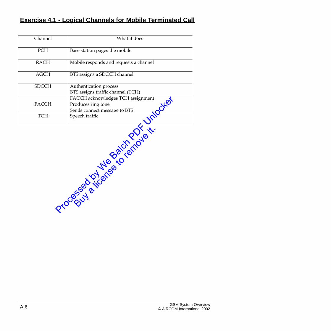
Exercise 4.1 - Logical Channels for Mobile Terminated Call
GSM System Overview© AIRCOM International 2002A-6
Channel What it does
PCH Base station pages the mobile
RACH Mobile responds and requests a channel
AGCH BTS assigns a SDCCH channel
SDCCH Authentication processBTS assigns traffic channel (TCH)
FACCHFACCH acknowledges TCH assignment
Produces ring tone
Sends connect message to BTSTCH Speech traffic
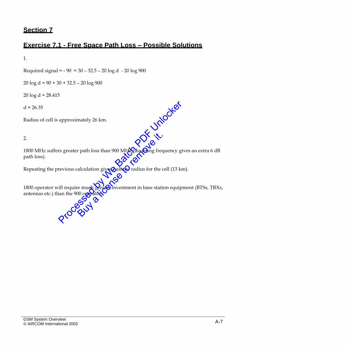
Section 7
Exercise 7.1 - Free Space Path Loss – Possible Solutions
1.
Required signal = - 90 = 30 – 32.5 – 20 log d - 20 log 900
20 log d = 90 + 30 + 32.5 – 20 log 900
20 log d = 28.415
d = 26.35
Radius of cell is approximately 26 km.
2.
1800 MHz suffers greater path loss than 900 MHz (doubling frequency gives an extra 6 dBpath loss).
Repeating the previous calculation gives half the radius for the cell (13 km).
1800 operator will require much greater investment in base station equipment (BTSs, TRXs,antennas etc.) than the 900 operator.
GSM System Overview© AIRCOM International 2002 A-7
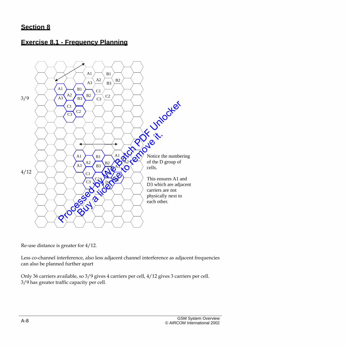
Section 8
Exercise 8.1 - Frequency Planning
A1 B1
A2 B2A3 B3
A1 B1 C1
C3A2 B2 C23/9 A3 B3
C1
C3C2
A1 Notice the numbering
of the D group of
cells.
A1 B1
A2A2 B2A3 B3 A3
4/12 D3C1
This ensures A1 and
D3 which are adjacent
carriers are not
physically next to
each other.
C2 D2C3 D1
Re-use distance is greater for 4/12.
Less co-channel interference, also less adjacent channel interference as adjacent frequenciescan also be planned further apart
Only 36 carriers available, so 3/9 gives 4 carriers per cell, 4/12 gives 3 carriers per cell.3/9 has greater traffic capacity per cell.
GSM System Overview© AIRCOM International 2002A-8
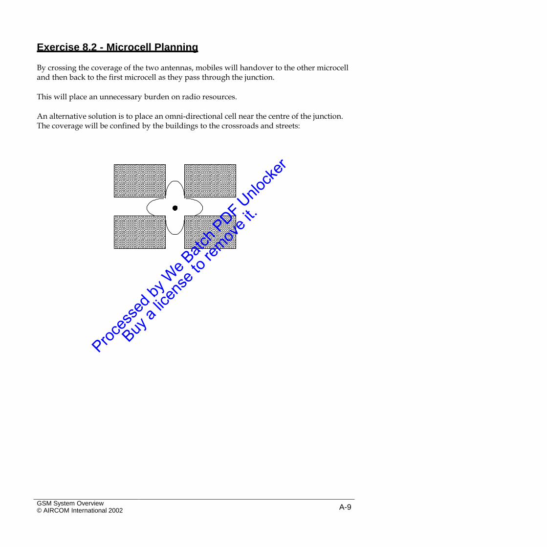
Exercise 8.2 - Microcell Planning
By crossing the coverage of the two antennas, mobiles will handover to the other microcelland then back to the first microcell as they pass through the junction.
This will place an unnecessary burden on radio resources.
An alternative solution is to place an omni-directional cell near the centre of the junction.The coverage will be confined by the buildings to the crossroads and streets:
GSM System Overview© AIRCOM International 2002 A-9
Section 9
Exercise 9.1 - Frequency Hopping – Comments
Although each cell is using four different frequencies at any one time, the neighbouringcells are also using the same four frequencies at the same time.
There are only four frequencies available, so at any moment all the cells are trying to use allthe frequencies. This would produce unacceptable interference.
To use frequency hopping, each cell must hop through a different set of frequencies than itsneighbours so that interference is not caused.
GSM System Overview© AIRCOM International 2002A-10
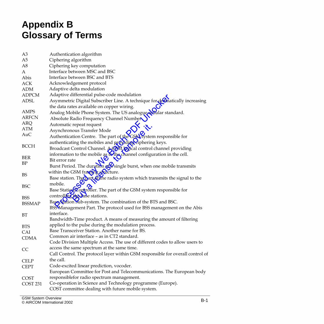
Appendix BGlossary of Terms
A3A5
A8
A
Abis ACK ADM ADPCM ADSL
Authentication algorithmCiphering algorithm
Ciphering key computation Interface between MSC and BSC Interface between BSC and BTS Acknowledgement protocol Adaptive delta modulationAdaptive differential pulse-code modulation
Asymmetric Digital Subscriber Line. A technique for dramatically increasing
the data rates available on copper wiring.
Analog Mobile Phone System. The US analogue cellular standard.
Absolute Radio Frequency Channel Number
Automatic repeat request
Asynchronous Transfer Mode
Authentication Centre. The part of the GSM system responsible for
authenticating the mobiles and providing ciphering keys.
Broadcast Control Channel. A GSM logical control channel providing
information to the mobile as to the channel configuration in the cell. Bit error rate
Burst Period. The duration of a single burst, when one mobile transmits
within the GSM framing structure.
Base station. The part of the radio system which transmits the signal to the
mobile.
Base Station Controller. The part of the GSM system responsible for
controlling the base stations.
Base Station Sub-system. The combination of the BTS and BSC.
BSS Management Part. The protocol used for BSS management on the Abis interface.Bandwidth-Time product. A means of measuring the amount of filtering applied to the pulse during the modulation process.Base Transceiver Station. Another name for BS. Common air interface – as in CT2 standard.Code Division Multiple Access. The use of different codes to allow users to access the same spectrum at the same time.
Call Control. The protocol layer within GSM responsible for overall control of
the call.
Code-excited linear prediction, vocoder.
European Committee for Post and Telecommunications. The European body responsiblefor radio spectrum management.Co-operation in Science and Technology programme (Europe). COST committee dealing with future mobile system.
AMPSARFCN ARQ ATM AuC
BCCH
BERBP
BS
BSC
BSSBSSMAP
BT
BTSCAI
CDMA
CC
CELPCEPT
COSTCOST 231
GSM System Overview© AIRCOM International 2002 B-1
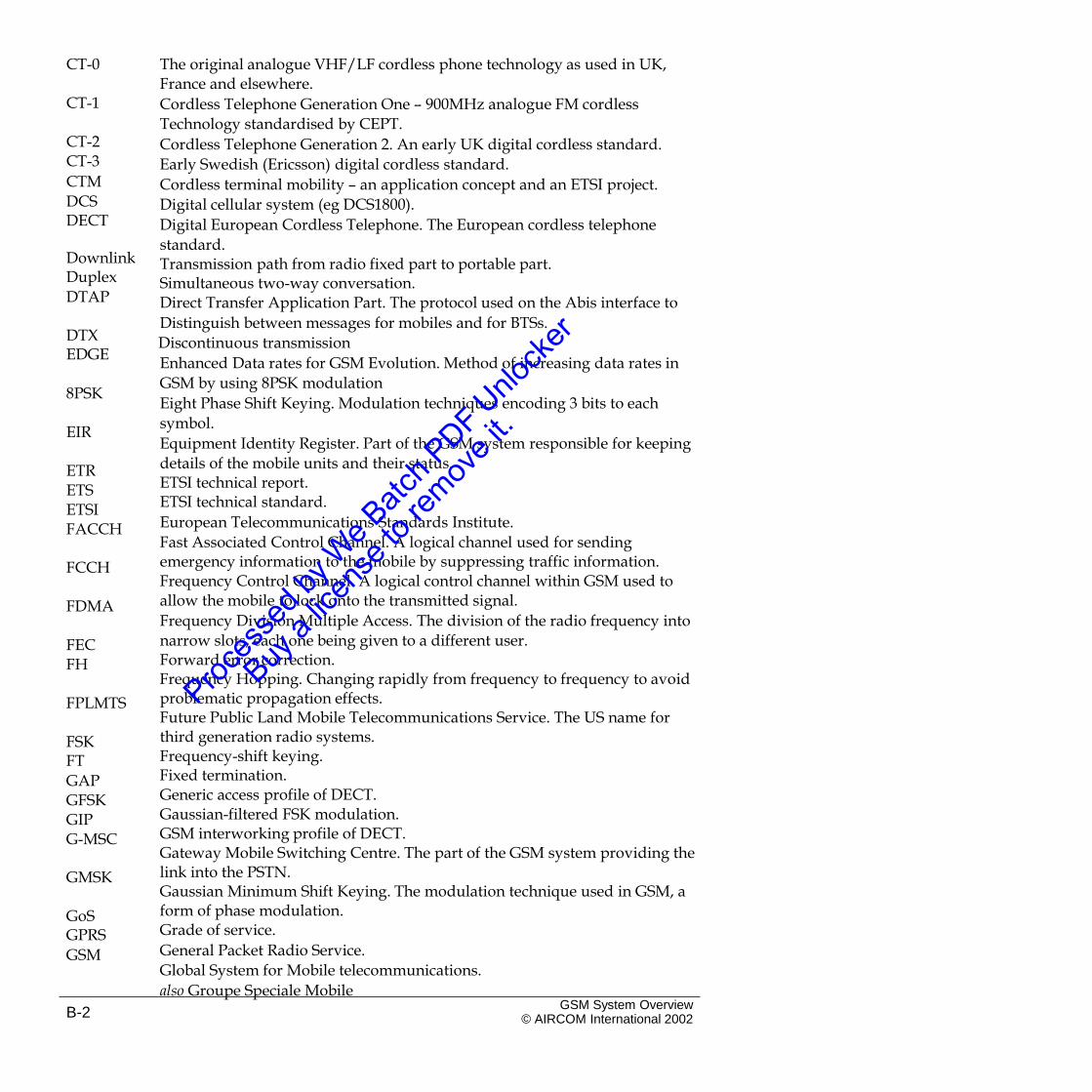
CT-0 The original analogue VHF/LF cordless phone technology as used in UK,France and elsewhere.
Cordless Telephone Generation One – 900MHz analogue FM cordless
Technology standardised by CEPT.
Cordless Telephone Generation 2. An early UK digital cordless standard.
Early Swedish (Ericsson) digital cordless standard.
Cordless terminal mobility – an application concept and an ETSI project.
Digital cellular system (eg DCS1800).
Digital European Cordless Telephone. The European cordless telephone
standard.Transmission path from radio fixed part to portable part. Simultaneous two-way conversation.Direct Transfer Application Part. The protocol used on the Abis interface to
Distinguish between messages for mobiles and for BTSs.
Discontinuous transmission
Enhanced Data rates for GSM Evolution. Method of increasing data rates in
GSM by using 8PSK modulation
Eight Phase Shift Keying. Modulation techniques encoding 3 bits to each
symbol.
Equipment Identity Register. Part of the GSM system responsible for keeping
details of the mobile units and their status. ETSI technical report.ETSI technical standard.
European Telecommunications Standards Institute.
Fast Associated Control Channel. A logical channel used for sending emergency information to the mobile by suppressing traffic information. Frequency Control Channel. A logical control channel within GSM used to allow the mobile to lock onto the transmitted signal.
Frequency Division Multiple Access. The division of the radio frequency into
narrow slots, each one being given to a different user. Forward error correction.Frequency Hopping. Changing rapidly from frequency to frequency to avoid problematic propagation effects.Future Public Land Mobile Telecommunications Service. The US name for third generation radio systems.Frequency-shift keying. Fixed termination.Generic access profile of DECT. Gaussian-filtered FSK modulation. GSM interworking profile of DECT.Gateway Mobile Switching Centre. The part of the GSM system providing the link into the PSTN.Gaussian Minimum Shift Keying. The modulation technique used in GSM, a form of phase modulation.Grade of service.
General Packet Radio Service.
Global System for Mobile telecommunications.
also Groupe Speciale Mobile
CT-1
CT-2CT-3
CTM
DCS DECT
DownlinkDuplex
DTAP
DTXEDGE
8PSK
EIR
ETRETS ETSI FACCH
FCCH
FDMA
FECFH
FPLMTS
FSKFT
GAP GFSK GIPG-MSC
GMSK
GoSGPRS
GSM
GSM System Overview© AIRCOM International 2002B-2
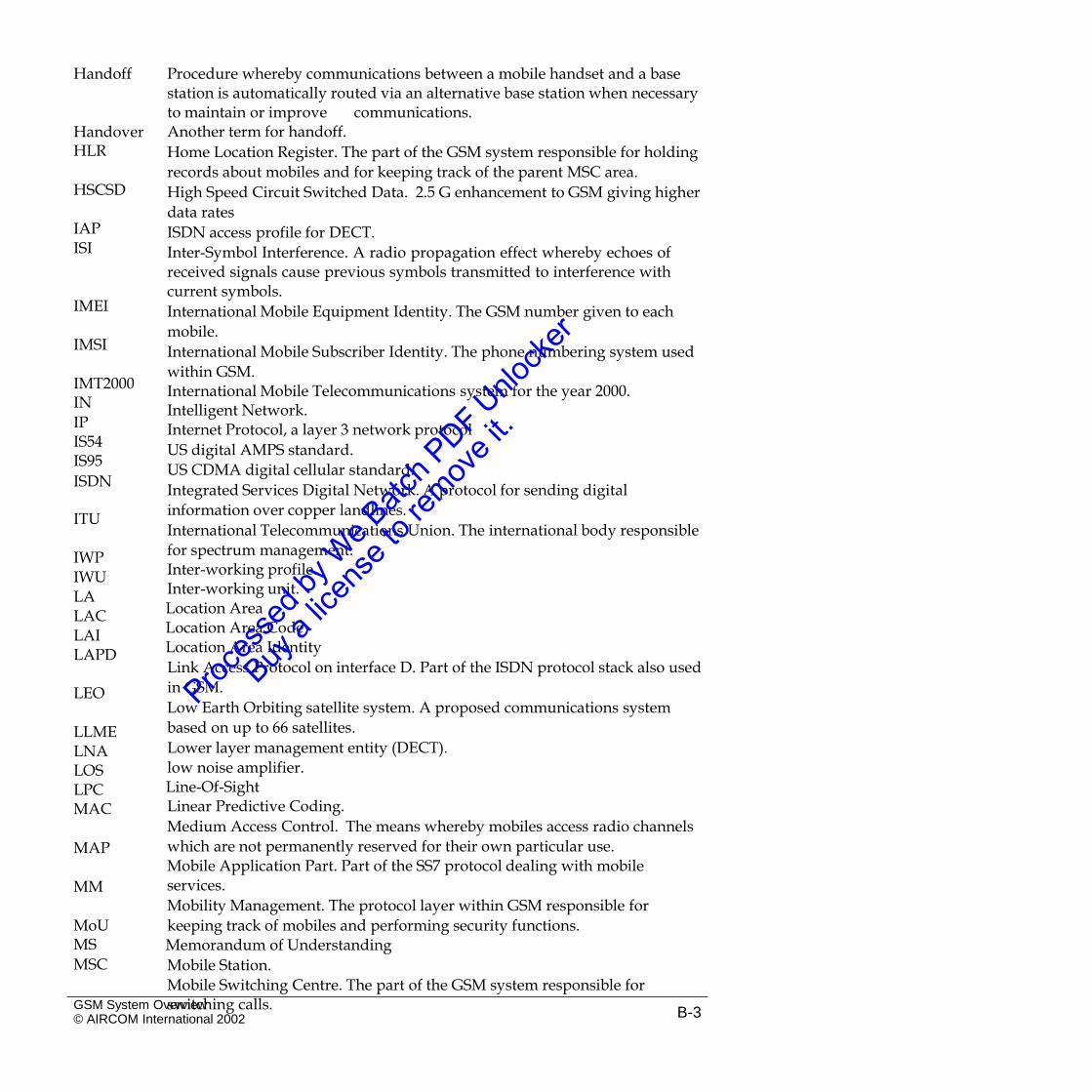
Handoff Procedure whereby communications between a mobile handset and a basestation is automatically routed via an alternative base station when necessary to maintain or improve communications.Another term for handoff.
Home Location Register. The part of the GSM system responsible for holding
records about mobiles and for keeping track of the parent MSC area.
High Speed Circuit Switched Data. 2.5 G enhancement to GSM giving higher
data rates
ISDN access profile for DECT.
Inter-Symbol Interference. A radio propagation effect whereby echoes ofreceived signals cause previous symbols transmitted to interference withcurrent symbols.
International Mobile Equipment Identity. The GSM number given to each
mobile.
International Mobile Subscriber Identity. The phone numbering system used
within GSM.International Mobile Telecommunications system for the year 2000. Intelligent Network.Internet Protocol, a layer 3 network protocol
US digital AMPS standard.
US CDMA digital cellular standard.
Integrated Services Digital Network. A protocol for sending digital
information over copper landlines.
International Telecommunications Union. The international body responsible
for spectrum management. Inter-working profile.Inter-working unit. Location Area Location Area CodeLocation Area Identity
Link Access Protocol on interface D. Part of the ISDN protocol stack also used
in GSM.
Low Earth Orbiting satellite system. A proposed communications system
based on up to 66 satellites.
Lower layer management entity (DECT).
low noise amplifier. Line-Of-SightLinear Predictive Coding.
Medium Access Control. The means whereby mobiles access radio channels
which are not permanently reserved for their own particular use. Mobile Application Part. Part of the SS7 protocol dealing with mobile services.
Mobility Management. The protocol layer within GSM responsible for
keeping track of mobiles and performing security functions. Memorandum of Understanding
Mobile Station.
Mobile Switching Centre. The part of the GSM system responsible for switching calls.
HandoverHLR
HSCSD
IAPISI
IMEI
IMSI
IMT2000IN
IP IS54IS95
ISDN
ITU
IWPIWU LA LAC LAI LAPD
LEO
LLMELNALOSLPCMAC
MAP
MM
MoUMS
MSC
GSM System Overview© AIRCOM International 2002 B-3
MSISDN Mobile Subscriber Integrated Services Digital Number. The numberingsystem used to contact GSM mobiles from other networks. Minimum shift keying modulation.Message Transfer Part. Part of the SS7 protocol stack. North American Digital CellularNational Colour Code
Nordic Mobile Telephone system. The Nordic analog cellular standard.
Operations and maintenance
Operations, administration and maintenance.
Operations and Maintenance Centre. The part of the GSM system responsible for monitoring network function.
private automatic branch exchange.
Paging and Access Grant Channel. A GSM logical control channel providing paging information and allowing mobiles to make access attempts.Private Branch Exchange (today has same meaning as PABX). Pulse Code Modulation. A simple form of speech coding. Personal communications network.
Personal Communications System at 1900 MHz. A variant of GSM working at
1900MHz designed for the US.
Personal Digital Cellular. The Japanese cellular standard.
Physical layer – lowest protocol layer.
Personal Handiphone System. The Japanese cordless telephone standard.
Public Land Mobile Network.
Private (or Professional)Mobile Radio. A radio system owned by the users
typically large companies. Plain old telephone service. Portable part.Phase shift keying modulation.
Public Switched Telephone Network.
Portable termination.
Quadrature Phase Shift Keying. A form of modulation whereby orthogonal
carriers are used to gain the maximum information from the channel.
MSKMTP NADC NCC NMT O&M OAM OMC
PABXPAGCH
PBXPCM
PCN PCS1900
PDCPHL PHS PLMN PMR
`POTSPP
PSK PSTN PT QPSK
Quantisation A process of representing samples of an analogue waveform by the nearestwhole number of predefined voltage steps.
RACH Random Access Channel. A GSM logical control channel used for makinguplink access attempts.
Radio access profile for DECT.
Radio Access NetworkRadio fixed part.
Radio Interface Layer. The protocol within GSM responsible for maintenance
of the radio interface. Radio local area network. Radio local loop.
Regular pulse excitation – long term predictor – speech coder user in GSM.
Radio Resource. The protocol layer within GSM responsible for providing a service over the air interface.Received signal strength indication.
Slow Associated Control Channel. A logical channel used alongside a traffic
RAPRAN RFP RIL
RLANRLL
RPE-LTP
RR
RSSISACCH
GSM System Overview© AIRCOM International 2002B-4
channel to send signalling information to and from the mobile.Synchronisation Control Channel. A GSM logical control channel providing synchronisation to the mobile.Signalling Control and Connection Part. Part of the SS7 protocol stack. Silence DescriptorSubscriber Identity Module. A small card within GSM mobiles which contains the subscriber identity.One-way communication.
Short Message Service. A feature within GSM whereby messages of up to 160
characters can be transmitted to mobiles.
SMS Service Centre. The part of the GSM system which handles short
messages.
Signed RESult . Produced by authentication algorithm.
Timing Advance
Total Access Communications System. The UK (and other European
countries) analogue cellular standard.Technical basis for regulation – ETSI standards.
Traffic Channel. The channel used in GSM to send subscriber information.
Transaction Capability Application Part. Part of the SS7 protocol stack. time division duplex.Time division multiplex.
Time Division Multiple Access. A system where users access all the frequency
but only for a limited time. TErrestrial Trunk RAdioTelecommunications Management Network. The concept of managing the network from a single point using a networked operations and maintenance system.
Temporary Mobile Subscriber Identity. A GSM number given to the mobile
during an encrypted call to prevent eavesdroppers being able to located the mobile.
Transcoder Rate Adapter Unit
Transmit/Receiver module. The GSM term for a single carrier card within a
BTS.
Universal Mobile Telecommunications Service. One name for the third generation mobile radio system.Communications path from portable part to fixed part.
Universal Personal Telecommunications. The fixed network equivalent of
third generation systems. Voice Activity DetectionVisitors Location Register. The part of the GSM system responsible for keeping track of a mobile’s position to the nearest location area.Very Small Aperture Terminal. A satellite communication system based on dishes around 1m across.Wireless Application ProtocolWireless Local Loop. The use of radio to replace copper wiring as a means of connecting the home to the PSTN.Wireless PABX. Wirelexx PBX.
SCCH
SCCPSID
SIM
SimplexSMS
SMS-SC
SRESTA TACS
TBRTCH
TCAP TDD TDM TDMA
TETRATMN
TMSI
TRAUTRX
UMTS
UplinkUPT
VADVLR
VSAT
WAPWLL
WPABXWPBX
GSM System Overview© AIRCOM International 2002 B-5
WRC World Radio Conference. The bi-annual international conferences todetermine the use of the radio spectrum. Wireless relay station.WRS
GSM System Overview© AIRCOM International 2002B-6

![SPECIFICATION & INSTALLATION GUIDE52 gsm to 450 gsm (Plain, Fine, Color Specific, Coated-G, Coated-M) 81 gsm to 350 gsm (Textured) 70 gsm to 100 gsm (Envelopes) ... Envelope Seam [1]](https://img.pdfslide.net/doc/110x75/5ebee13946efcd7097328efd/specification-installation-52-gsm-to-450-gsm-plain-fine-color-specific.jpg)


![Gsm Training 2[1]](https://img.pdfslide.net/doc/110x75/545f7465af79593f708b4ea3/gsm-training-21.jpg)
![GSM Q-A[1]](https://img.pdfslide.net/doc/110x75/5451eddfaf795915308b4b51/gsm-q-a1.jpg)


![1[1].Gsm Overview](https://img.pdfslide.net/doc/110x75/577cd8591a28ab9e78a104e1/11gsm-overview.jpg)
![01 - GSM Training Pack - Basics of the GSM[1]](https://img.pdfslide.net/doc/110x75/577d23851a28ab4e1e9a0467/01-gsm-training-pack-basics-of-the-gsm1.jpg)


![Gsm rf-optimization[1]](https://img.pdfslide.net/doc/110x75/555a60dbd8b42a47748b5372/gsm-rf-optimization1.jpg)