Embed Size (px)
Citation preview
*g- IYIE
rf-1 r 8o RPr
t0ME52USN
d()oP1(0
d
()(dC)!
-Qo
-y, Ifttu=r)!
oa ll
coo.=Nd$bx0otr.c 0,)
-l=o>8g
a=
bUcdOOEboc.(d cd!E>P26s9'
Ed
-2. B'Ee=(d48.tro.6(soi9Ee€a.r
Fifth Semester B.E. Degree Examination, June/July 2Ol4Design of Machine Elements - I
I TMC: J,,,,'t'
'' f' I',
'" /:r:t :!i:
hrs. Max. Marks:10C,,Note: 7. Answer FIVEfull questions, selecting
at least TWO questions from each part. ;i"':.,,,,,, '1i'
2. IIse of design datu handbook is permitted.
PART _ Adiagrams for a ductile material and a brittle mate-{a$'"'hnd show the
::.-n (05 Marks)
directions.(06 Marks)
the stress-strainon them.
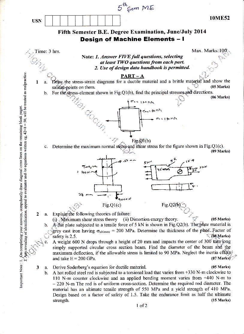
b. Fort lement shown in Fig.Q1(b), find the principal
fr:l$oFl?r
nooo tJ
Fig.Q1(c) Fig.Q2@%_
\*t; '=J\ .!hr
2 a. Explq4-ft following theories of failure:(i) -'M imum shear stress theory (ii) .
b. A.nta plate subjected to a tensile force c
theory (ii) Distortion energy theory. (05 Marks)l:,
".r Fish@l(b)c. Determine the maximum normal rq*S qn{ bh'ear stress for the figure shown in Fig.Ql(c).'fu#-.: (09 Marks)
4*Se^-
ffi2$ rn'r 4
t
ile force of 5 kN is shown in Fig.Q2(b). Thdjlfate material ts: E b. A.flat plate sublected to a tensrle torce ot 5 kN ls shown m llg.Qz(b). rne.S,rate mateflal ls
iE - giey cast iron having Gultimate : 200 MPa. Determine the thickness of the plate_- Factor ofH $ uJ rur.ty is 2.5. tPgfrIarks)
BE _**-*s c. A weight 600 N drops through a height of 20 mm and impacts the center of 300 mi.'tl;*ong
E E ,." . simply. supported circular cross section beam. Find the diameter of the beam ahd**!he
5 S,* \ maximum deflection, if the allowable stress is limited to 90 MPa. Neglect the inertia lf$q}i*j;' and take E:200 GPa. (07 Marksl',,''
€ 3 a. Derive Soderberg's equation for ductile material. (05 Marks)V" b. A hot rolled steei rod is subjected to a torsional load that varies from +330 N-m clockwise tog 110 N-m counter clockwise and an applied bending moment varies from +440 N-m tog 220 N-m The rod is of uniform cross-section. Determine the required rod diameter. The
material has an ultimate tensile strength of 550 MPa and a yield strength of 410 MPa.Design based on a factor of safety of 1.5. Take the endurance limit as half the ultimatestrength.
I of2(15 Marks)
10M852
4 a. Explain the stresses induced in a screw fastening subjected to static, dynamic and impactloading. (12 Marks)
b. A bolt is subjected to initial loading of 5 kN and final tensile load of 9 kN. Determine the
./ size of the bolt, if the allowable stress is 80 MPa and K: 0.05. (08 Marks)
,, --ta'11"' llltlr-" pART-B .. "lii
""'{,' ,'A horizontal steel shaft, supported on bearings "A" at the left end and "B" at the Si{,&t ena,
;i'irrries two gears "C" & "D", located at distances 250 mm and 400 mm respectiysly". om the
cenfeq hnes of left and right end bearings. The pitch diameter of gear C is 600 @'h*.pnd that ofgeaF-R-fu2OO mm. The pressure angle is 20o. The distance between the cgqef lines. of the
UearingS.iS, 00 mm. The shaft transmits 20 kW power at 120 rpm. The,.po$dr is delivered tothe shaft hf$ar C and is taken out at gear D in such a manner that thwfiod'th pressure F+c and
F+o of gear6={,9ana D act vertically downwards. Find the diameteffind shaft, if the workingstresses are100ffiPajn tension and 56 MPa in shear. The gear C"AnFp weigh 950 N and 350 Nrespectively. Take C,n = J.5 and Cr : L.2. (20 Marks)
6 a. Design a cotter joint=g.gtgrrtain an axial load of 100 -1*T'{.
'Atrlowable stress in tension 80 MPa.
Allowable stress in c ssion 120 MPa. Alloffile shear stress 60 MPa. Allowablebearing pressure 40 MPa. . /,,u* , (10 Marks)
b. Design a flanged coupling hi']4nnect theJ$.!$ of motor and pump transmitting 15 kWpower at 600 rpm. Select C40 Jtdel fur sha{Wd Crs steel for bolts, with factor of safety:2.Use allowable shear stress for Cas\"ffih flafiles : 15 N/mm2, oauowabre : 162 N/mm2 ; and
ralowabre : 81 N/mm2 for bolts o : l5,:ftffi@# and t : 76 N/mm2. (10 Marks),,,, -.. ,l {
7 a. Design a double riveted lap joiriffih chain S/,,irttrng for a mild steel plates of 20 mm thicktaking the allowable valueq-.qf stress in she&'tension and compression to 60, 90 and
120 MPa respectively. ,-.,,,]'"'' (10 Marks)
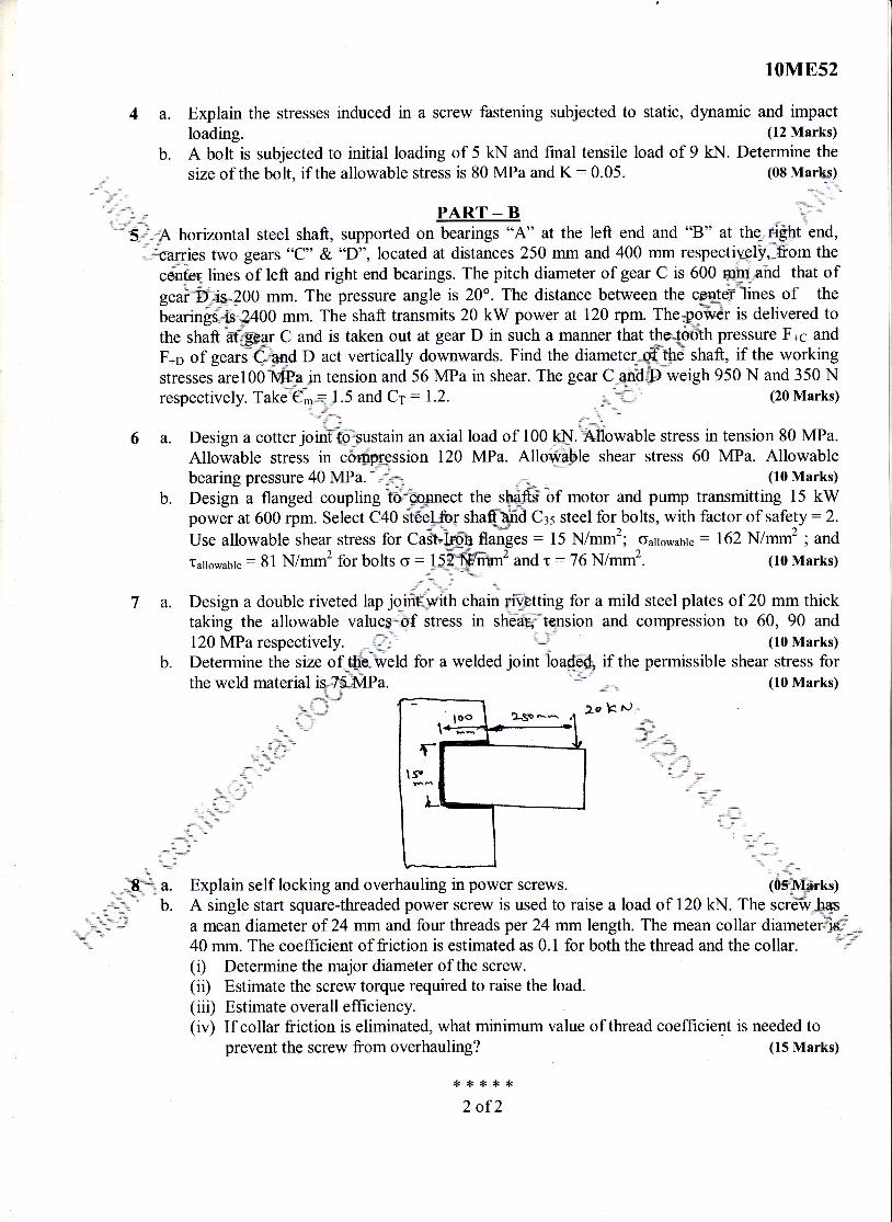
b. Determine the size of &h"'fueld for a welded ioint loaffik if the permissible shear stress for120 MPa respectively. ,,..''1,:!,' (10 Marks)
Determine the size of..@'fueld for a welded joint loaffi if the permissible shear stress fortheweldmaterial6TSMPa'
fur ,"*, ,,I t.==-{*:.-trrfru%y-"qq l'*-| II rl--- I
"-'i,\--ll
lllllla ' .:""-''-: .-
,Cff;u. Explain self locking and overhauling inpower screws. tGffirO+' b. A single start square-threaded power screw is used to raise a load of 120 kN. The scr€iv,@_,_i:t:' b. A single start square-threaded power screw is used to raise a load of 120 kN. The scrdft-@
2,1i,{.:t; a mean diameter of 24 mm and four threads per 24 mm length. The mean collar diameterdi#='q! 40 mm. The coefficient of friction is estimated as 0.1 for both the tluead and the collar.
(i) Determine the major diameter of the screw.(ir) Estimate the screw torque required to raise the load.(iii) Estimate overall efficiency.(iv) If collar friction is eliminated, what minimum value of thread coeflicient is needed to
prevent the screw from overhauling? (15 Marks)
{<rf*xr.2 of2
a.
b.
oo(J(B
(d
o{.)
E9oo#
69=r,!
oo ll
trco,= a't(!+:'r 50Y0)Oq_cooB8E
a=
o,ocdO
ooc.E$>*-66-
-(,6
-ats'tso.A
9Eto-a tEEE!O
ooog ol)
o=a"AiE>o
U<- (\]
C)!z
o
USN
\t.,,,tta "
Time: 3 hrs. Max. Marks:100f,T^1-- a /- - -. --- '-- Dtt/D 2--r, -., - ' ' - 1t' ' . . . ' r' ' )t' ,' .:,,::,,,: Note: L. Answer FIVEfutt questions, selecting #';
"''"1'1.
., at least TWO questionsfrom each part. ..
,,, =,,, "t'
"'r' ,rr' 2. Use of thermodynamics data book is permitted. 1'';."-
-J ----- ------J
'1 :::::.
DA D'r' AI)I PART-A A$':1 a. DefiriUttrr-bomachine. Classifythemonbasisofworktransfer. ,=
t* "= (04lvlarks)b. Define
$.e mlnyng^efficiencies of power absorbing turbomachfuaes:
i) Total-to-totalefficiencyii) Static-to-static effrciency , *o.,-\ ''' (06 Marks)
c. Explain specific speed and specific power. (04 Marks)d. A model turbine 1 m in diameter acting under a head of 2 mruns at I50 rpm. Estimate the
scale ratio if the protoffiedevelops 20 MW under a head of 225 m with a specific speed of100. (06 Marks)
2 a. Define polytropic efficiency of a compressoi i' (04 Marks)b. What is reheat factor in a multistage turbine? Prove that R.F is greater than unity. (08 Marks)c. In a three stage turbine the pressure,i*ieof each stage is 2 and the stage efficiency is 75%o.
Calculate the overall efficiency aad at=frctor. (08 Marks)
3 a. Derive an alternate form of,Etibr's turbine eUuqtion and explain the significance of eachenergy components. (10 Marks)
b. At a 50oh reaction stage axial flow turbine, the mean,blade diameter is 0.60 mtr. Themaximum utilization factor is 0.85 and steam flow rate is tZ tgls. Calculate the inlet andoutlet absolute velocities and power developed if the speed U.S500 rpm. (10 Marks)" 'w-
4 a. Derive an o-N ression of theoretical head capacity relationship oErqitial outward flow devices(centrifugatrnachines). a\
(10 Marks)b. An inward flow reaction turbine has outer and inner diameter wheel ry 1 m and 0.5 m
resndptiVely. The vanes are radial at inlet and discharge is radial at outlefand fluid inters theve{b3 at an angle of 10o. Assuming the velocity of flow to be constant and equal to 3 m/sec.Find: i) Speed of wheel, ii) Vane angle at outlet, iii) Degree of reaction. ;rrr;"(10 Marks)
Fifth Semester B.E. Degree Examinationo June/July 2Ol4
Turbomachines
PART - BWhat is compounding or staging? Name the different compounding methods.The data pertaining to an impulse turbine is as follows:Steam velocity : 500 m/sec, blade speed: 200 m/sec, exit angle atmeasured from tangential direction, nozzle angle : 20o. Neglectingwhen passing through blade passages. Calculate:i) Inlet angle of moving bladeii) Exit velocity and directioniii) Work done per kg of steamiv) Power developedv) Diagram effrciency
10ME56
'' .=.
(0a M.aq!s)
d .i ,.ir,ri
moving blade :23'o"i'
the effect of friction
I of2
(16 Marks)
11) worKdone.pet^:ems_oy lmpeue, :,. .iii) Manometric effrciffi;. \,,::ir'/! (08 Marks)
s i'' :.1-",* #h ",T
8 a. Explain the phenomena of surg"i$;.lpJlirg ihd chocking in centrifugal compressor stage.
#'r;* " (06 Marks)
b. Draw velocity triangles at the entry d@=r&it for the axial compressor stage. (06 Marks)
c. An axial compressor/blower supplgqraifu: ace at the rate of 3 kg/sec. The atmosphericconditions being 100 kPa and'-tfl.J0 K. the blower efficiency is 80% and mechanicaleffrciency is 85%. The porlrcr."supplied to {$f$W. Estimate the overall effrciency andpressure developed ,
T** 4. " : (08 Marks)
,-i,l '$ {< {< {<:n * *$."
' 'i,1'
,d$t """'i.,,v=.....,.
- ,.'''i""'' -;irl"
:'o,._ _a., ,,t)i; il1:^,1t,
::, ;, .,, - '::'-
,,, .i,,.,,..
'"" " ''.,*-,
rl.,,, 't! ' ' - rir ;li
.. ;t =:, "' . ,.' ,,i" ,,a"
E[ , l"'ri::'
10M856
6 a. Obtain an expression for the workdone per second by water on the runner a fehon Wheeland Hydraulic efficiency. (10 Marks)
b. A Kaplan turbine has an outer diameter of 8m and inner diameter as 3m and developing30,00-0 KW at 80 rpm under a head of 12 m. The discharge through the runner is 300 m3/sec.
tfihe hydraulic edciency isglYo,determine: +i
*;p*h,* D Inlet and outlet blade angles 'i;*=" '''
L,Ipl'-i, ,, ii) Mechanical efficienc, t't'o"
,,i-),,, f
. q. ,r!!!f) :i.,::- iii) Overall efficiency ''ll5r$ Marks)
fls"; it .,".7 a. Der-{{$l,JFg expression for the minimum speed for starting a centrifugal p@ (12 Marks)
b. A cerid!$gal pump having outer diameter equal tcr_ two lim3s ttreilpe.f'diam9te1 a1d ruyinSat t200 i1i$d;,ryorks against a total head of 75 m. The velocity of flow through the impeller i
constantdiameter of t ller is 60 cm and width at outlet is 5 c
2 of2
10M854USN
Fifth Semester B.E. Degree Examination, June/July 2Ol4Dynamics of Machines
ffiTime: 3 hrs. Max. Marks: lp"q\
,,fut 'r,., at least TWO questions from each part. (,,.i,,,
. "*r,* PART - A '"i :t
€ I a." Explain equilibrium with respect to two force and three force members. ,lj* (04 Marks)
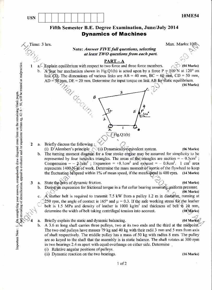
E b. i$&"#q bar mechanism shown in Fig.Ql(b) is acted upon by a force P 7fi00 at 120o on
E lirl{=$q. The dimensions of various links are AB : 40 mm, BC : 6 _ry CD : 50 mm,
! AD : $Stnm, DE :20 mm. Determine the input torque on link AB &*Btatic equilibrium.E .n d ", r (16 Marks)
t3 "':"'''ti''" \a? \.E? \{,-
E a' ,-\r€oB Ag E p-*iiffig.e1(b)
%: '-
a s "l -'\."' \G o /.\ h! ^ r , ,'E ; (i) D'Alembert's principle r'{ii) DynamicallyQqlivalent system. (06 Marks)
E' E b. The turning moment diagpaur for a four stroke engine may be assumed for simplicity to be
; € represented by four isosceles triangles. The areas of the triangles are suction : - 0.5cm' ;E
= ^-^-^^-^--- -- :- -- ^."^=-.-2 - E---^-^-^i^-- -
ro 1^-^-z ^-t"i-"^--r-^--^. - no^*2 1 ^*2 ^-^^; E represented by four isosoeles triangles. The areas of ffitriangles are suction : - 0.5cm2 ;
€E Compression: - ?.Gri; Expaniion: *8.tcm'arid'e*+pust - - 0.8cm2. I cni area
€ 3 represents 1400"il{:F of work. Determine the mass momeritbf.iqertia of the flywheel to keepof work. Determine the mass momeritbf'.i*prtia of the flywheel to keep
:d within loZ of mean speed, if the meanspeed is 400 rpm. (14 Marks)
.E g rlPrvDvuLD a.-a-luw#, vl YvurN. uwLvrrllllv Lrlw llrQoD rllvlllwrrE;s1 nElllur@ vr
E ; the fluctuatiqrr bfi'Speed within loZ of mean speed, if the meanspqed is z
48. ,;" ' (,F' d "_;1h." ",a N %u%' E"*?-
: S 3 a. State the laws of dynamic friction. ' i;t: E 3 a. State the=ffis of dynamic friction. ' *u* (04 Marks)
E E b. Deri14i6h expression for frictional torque in a flat collar bearing assuffii&.1#niform pressure.
U f _;,,.
(06 Marks)
; E c. A leather belt is required to transmit 7.5 kW from a pulley 1.2 m in diafrtfe[,,running ato.=iE " '.250 rpm, the angle of contact is 165o and p:0.3. [f the safe working stress tr#. e leather
;'C belt is 1.5 MPa and density of leather is 1000 kg/mr and thickness of belt is l0 mm,
i-E determine the width of belt taking centrifugal tension into account. (leM*rts;ts>Fgo * t '"6_F"''"
:' I a. Briefly explain the static and dynamic balancing. (04 Marks)._" _;hi b. A 3.6 m long shaft carries three pulleys, two at its two ends and the third at the midpointTd'
g The two end pulleys have masses 79 kg and 40 kg with their radii 3 mm and 5 mm from axis2 of shaft respectively. The middle pulley has a mass of 50 kg with radius 8 mm. The pulley:E are so keyed to the shaft that the assembly is in static balance. The shaft rotates at 300 rpm
a in two bearings 2.4 mapart with equal overhangs on either side. Determine.E (D Relative angular poiitiorr of pulleys.
(ii) Dynamic reaction on the two bearings. (16 Marks)
I of2
10ME54
PART _ B
,,- . 5 a. With usual notations, explain primary and secondary unbalanced forces of recipr":r11ffi""' ''.:.,;--., masses. (05 Mek$"'{rq,,ry,,d= b. A five cylinder inline engine running at 500 rpm has successive cranks at 144" agart* The**,7ri
distance between the cylinder line is 300 mm. Piston stroke is 240 mm, length ofp@ecting*F;- .1od is 480 mm. Examine the engine for balance of primary and seconda;ry*Y6?des and
t-ffiuples. Find the maximum value of these and position of central :y hich these
ffim,U* values occur. The reciprocating mass for each cylinder is 150 )+k": ,t/- (15 Marks),r-"t"-'1f- "'}d
6 a. ?.:fi:e=tp.'Pllowing :
lil :enijd)ffi:ss (ii) Hunting (iii) Governer power Uffi Stutititv(v) Isochroi@governer. * t q,,r. (10 Marks)-^x::f E"
b. A portor govdurer."-[as all four arms 300 mm long, the(v) Isochroi@governer. *t',1 {r. (10 Marks)A portor govdaie-6".[as all four arms 300 mm long, the uffi hrms are pivoted on axis ofrotation and lowerprpns are attached to the sleeve at ffitance 35 mm from the axis. Themass of each ball i3?tsC and the load on the sleevg i$d4O N. Determine the equilibriumspeed for two extreme ffi*iof 200 mm and 260 mrrtffi#trotation of governer balls. (10 Marks)
* trtB l'7 a. With usual notations and dirigrflq derive an p4pSsion for the gyroscopic couple producedby a rotating disc. ,( ^ (08 Marks)
b. Each road wheel of motor cycle hdu$.fuareilt of inertia of 2 kg-*'. The rotating parts of theengine of the motor cycle, has a M.$:$f.e- 2 kg-rr]. The speed of the engine is 5 times thespeed of the wheel and is in the,,ffi-sbnse. The mass of the motor cycle with rider is 200kg and its C.G is 500 mm aboq 4iound levet, The diameter of the wheel is 500 mm, themotor cycle is travelling at 15fus on a curveffiO.A radius. Determine(r) Gyroscopic couple, centiifugal couple, over tt#ing and balancing couple in terms of
angle of heel. v \ dilu*(ii) Angle of heel. flP
n'tu==,, (12 Marks)
fi
speed o12@ipm. Determine '''.,*'(r) Thffiius of the nose arc. d0t eh:ffi.b.t r; acceleration of the roller centre when the roller in contact {-ffi__.#%t the end of one of the straight flanks adjacent to the nose and
4 {i}i) The acceleration of roller centre at peak.
:{'i{-""i
8 A straight sided-caffis both sides tangential to the base circie,-*ith a radius of 25 mm. Thetotal angle ofafifu is 120o, A lift of 10 mm is given to the roller 20*ryqdiameter, the centre ofwhich mov a straight line, passing through the axis of the c,imThe crank shaft has a
&&he cam
w(2g.Mark$*u{"1
2 of2